catalog cuts
TRANSCRIPT

Catalog Cuts
created 12/16/2005 09:03:04 AM
for
ART MUSEUM OF WESTERN VIRGINIA - WITH GASKETING REVISIONS
Sorted by DHI Sequence
Prepared By
COMMONWEALTH DOOR & HARDWARE1125 INTERVALE DR
SALEM VA 24153Phone (540) 387-0161 Fax (540) 387-0469
1775
PDF created by Specworks®
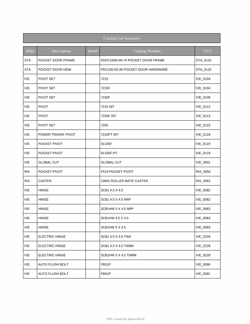
Catalog Cut Summary
Mfgr Description Item# Catalog Number CUT
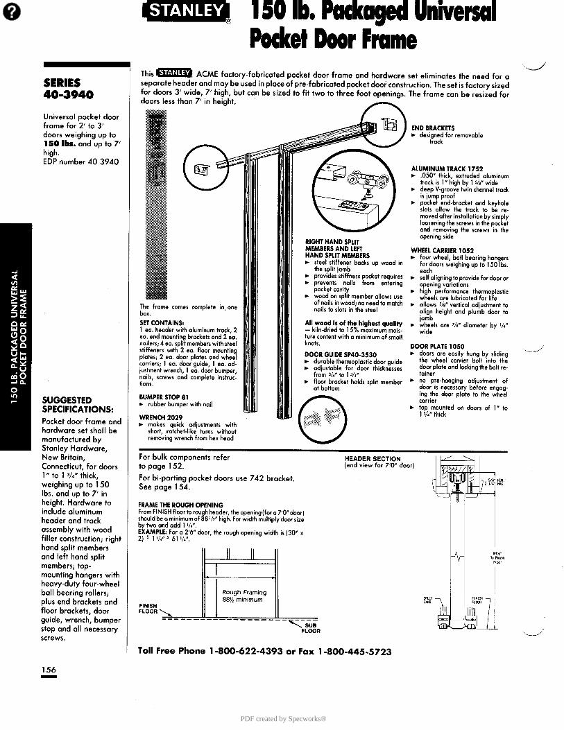
STA POCKET DOOR FRAME PDFC150N-00-70 POCKET DOOR FRAME STA_0115
STA POCKET DOOR HDW PDC150-00-36 POCKET DOOR HARDWARE STA_0115
IVE PIVOT SET 7215 IVE_0104
IVE PIVOT SET 7215F IVE_0104
IVE PIVOT SET 7230F IVE_0108
IVE PIVOT 7215 INT IVE_0112
IVE PIVOT 7230F INT IVE_0113
IVE PIVOT SET 7255 IVE_0115
IVE POWER TRANSF PIVOT 7215PT INT IVE_0118
IVE POCKET PIVOT 91105F IVE_0119
IVE POCKET PIVOT 91105F-PT IVE_0119
IVE GLOBAL CUT GLOBAL CUT IVE_5001
RIX POCKET PIVOT F519 POCKET PIVOT RIX_0050
RIX CASTER 10602 ROLLER MATE CASTER RIX_0061
IVE HINGE 3CB1 4.5 X 4.5 IVE_0082
IVE HINGE 3CB1 4.5 X 4.5 NRP IVE_0082
IVE HINGE 3CB1HW 5 X 4.5 NRP IVE_0083
IVE HINGE 3CB1HW 4.5 X 4.5 IVE_0083
IVE HINGE 3CB1HW 5 X 4.5 IVE_0083
IVE ELECTRIC HINGE 3CB1 4.5 X 4.5 TW4 IVE_0228
IVE ELECTRIC HINGE 3CB1 4.5 X 4.5 TW8M IVE_0228
IVE ELECTRIC HINGE 3CB1HW 5 X 4.5 TW8M IVE_0228
IVE AUTO FLUSH BOLT FB31P IVE_0090
IVE AUTO FLUSH BOLT FB41P IVE_0091
PDF created by Specworks®
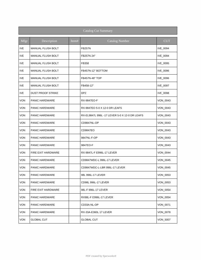
Catalog Cut Summary
Mfgr Description Item# Catalog Number CUT
IVE MANUAL FLUSH BOLT FB257N IVE_0094
IVE MANUAL FLUSH BOLT FB257N 24" IVE_0094
IVE MANUAL FLUSH BOLT FB358 IVE_0095
IVE MANUAL FLUSH BOLT FB457N-12" BOTTOM IVE_0096
IVE MANUAL FLUSH BOLT FB457N-48" TOP IVE_0096
IVE MANUAL FLUSH BOLT FB458-12" IVE_0097
IVE DUST PROOF STRIKE DP2 IVE_0098
VON PANIC HARDWARE RX-9847EO-F VON_0043
VON PANIC HARDWARE RX-9847EO 5-0 X 12-0 DR LEAFS VON_0043
VON PANIC HARDWARE RX-EL9847L 996L -17 LEVER 5-0 X 12-0 DR LEAFS VON_0043
VON PANIC HARDWARE CD9847NL-OP VON_0043
VON PANIC HARDWARE CD9847EO VON_0043
VON PANIC HARDWARE 9847NL-F-OP VON_0043
VON PANIC HARDWARE 9847EO-F VON_0043
VON FIRE EXIT HARDWARE RX-9847L-F E996L-17 LEVER VON_0044
VON PANIC HARDWARE CD9847WDC-L 996L-17 LEVER VON_0045
VON PANIC HARDWARE CD9847WDC-L-LBR 996L-17 LEVER VON_0045
VON PANIC HARDWARE 98L 996L-17 LEVER VON_0053
VON PANIC HARDWARE CD98L 996L-17 LEVER VON_0053
VON FIRE EXIT HARDWARE 98L-F 996L-17 LEVER VON_0054
VON PANIC HARDWARE RX98L-F E996L-17 LEVER VON_0054
VON PANIC HARDWARE CD33A-NL-OP VON_0071
VON PANIC HARDWARE RX-33A-E360L 17 LEVER VON_0078
VON GLOBAL CUT GLOBAL CUT VON_5007
PDF created by Specworks®
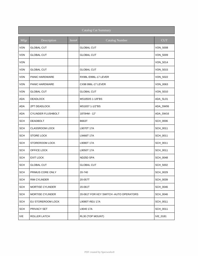
Catalog Cut Summary
Mfgr Description Item# Catalog Number CUT
VON GLOBAL CUT GLOBAL CUT VON_5008
VON GLOBAL CUT GLOBAL CUT VON_5009
VON VON_5014
VON GLOBAL CUT GLOBAL CUT VON_5015
VON PANIC HARDWARE RX98L E996L-17 LEVER VON_5022
VON PANIC HARDWARE CX98 996L-17 LEVER VON_0063
VON GLOBAL CUT GLOBAL CUT VON_5010
ADA DEADLOCK MS1850S 1-1/8"BS ADA_SL01
ADA 2PT DEADLOCK MS1837 1-1/2"BS ADA_SW06
ADA CYLINDER FLUSHBOLT 1870HM - 12" ADA_SW16
SCH DEADBOLT B663T SCH_0006
SCH CLASSROOM LOCK L9070T 17A SCH_0011
SCH STORE LOCK L9466T 17A SCH_0011
SCH STOREROOM LOCK L9080T 17A SCH_0011
SCH OFFICE LOCK L9050T 17A SCH_0011
SCH EXIT LOCK ND25D SPA SCH_0048
SCH GLOBAL CUT GLOBAL CUT SCH_5002
SCH PRIMUS CORE ONLY 20-740 SCH_0029
SCH RIM CYLINDER 20-057T SCH_0039
SCH MORTISE CYLINDER 20-061T SCH_0046
SCH MORTISE CYLINDER 20-061T FOR KEY SWITCH -AUTO OPERATORS SCH_0046
SCH EU STOREROOM LOCK L9080T-REU 17A SCH_0011
SCH PRIVACY SET L9040 17A SCH_0011
IVE ROLLER LATCH RL30 (TOP MOUNT) IVE_0181
PDF created by Specworks®
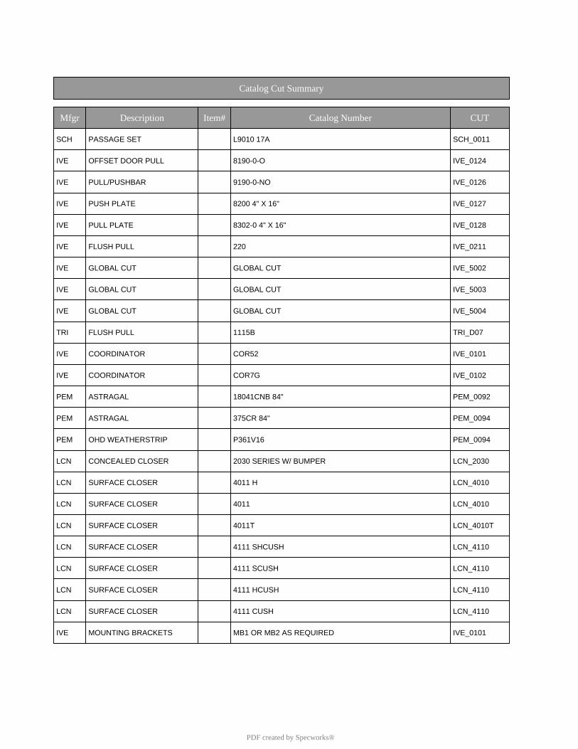
Catalog Cut Summary
Mfgr Description Item# Catalog Number CUT
SCH PASSAGE SET L9010 17A SCH_0011
IVE OFFSET DOOR PULL 8190-0-O IVE_0124
IVE PULL/PUSHBAR 9190-0-NO IVE_0126
IVE PUSH PLATE 8200 4" X 16" IVE_0127
IVE PULL PLATE 8302-0 4" X 16" IVE_0128
IVE FLUSH PULL 220 IVE_0211
IVE GLOBAL CUT GLOBAL CUT IVE_5002
IVE GLOBAL CUT GLOBAL CUT IVE_5003
IVE GLOBAL CUT GLOBAL CUT IVE_5004
TRI FLUSH PULL 1115B TRI_D07
IVE COORDINATOR COR52 IVE_0101
IVE COORDINATOR COR7G IVE_0102
PEM ASTRAGAL 18041CNB 84" PEM_0092
PEM ASTRAGAL 375CR 84" PEM_0094
PEM OHD WEATHERSTRIP P361V16 PEM_0094
LCN CONCEALED CLOSER 2030 SERIES W/ BUMPER LCN_2030
LCN SURFACE CLOSER 4011 H LCN_4010
LCN SURFACE CLOSER 4011 LCN_4010
LCN SURFACE CLOSER 4011T LCN_4010T
LCN SURFACE CLOSER 4111 SHCUSH LCN_4110
LCN SURFACE CLOSER 4111 SCUSH LCN_4110
LCN SURFACE CLOSER 4111 HCUSH LCN_4110
LCN SURFACE CLOSER 4111 CUSH LCN_4110
IVE MOUNTING BRACKETS MB1 OR MB2 AS REQUIRED IVE_0101
PDF created by Specworks®
Catalog Cut Summary
Mfgr Description Item# Catalog Number CUT
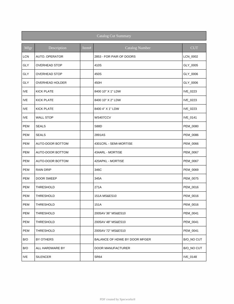
LCN AUTO. OPERATOR 2853 - FOR PAIR OF DOORS LCN_0002
GLY OVERHEAD STOP 410S GLY_0005
GLY OVERHEAD STOP 450S GLY_0006
GLY OVERHEAD HOLDER 450H GLY_0006
IVE KICK PLATE 8400 10" X 1" LDW IVE_0223
IVE KICK PLATE 8400 10" X 2" LDW IVE_0223
IVE KICK PLATE 8400 4" X 1" LDW IVE_0223
IVE WALL STOP WS407CCV IVE_0141
PEM SEALS S88D PEM_0080
PEM SEALS 2891AS PEM_0086
PEM AUTO-DOOR BOTTOM 4301CRL - SEMI-MORTISE PEM_0066
PEM AUTO-DOOR BOTTOM 434ARL - MORTISE PEM_0067
PEM AUTO-DOOR BOTTOM 420APKL - MORTISE PEM_0067
PEM RAIN DRIP 346C PEM_0069
PEM DOOR SWEEP 345A PEM_0075
PEM THRESHOLD 271A PEM_0016
PEM THRESHOLD 151A MS&ES10 PEM_0016
PEM THRESHOLD 151A PEM_0016
PEM THRESHOLD 2005AV 36" MS&ES10 PEM_0041
PEM THRESHOLD 2005AV 48" MS&ES10 PEM_0041
PEM THRESHOLD 2005AV 72" MS&ES10 PEM_0041
B/O BY OTHERS BALANCE OF HDWE BY DOOR MFGER B/O_NO CUT
B/O ALL HARDWARE BY DOOR MANUFACTURER B/O_NO CUT
IVE SILENCER SR64 IVE_0148
PDF created by Specworks®
Catalog Cut Summary
Mfgr Description Item# Catalog Number CUT
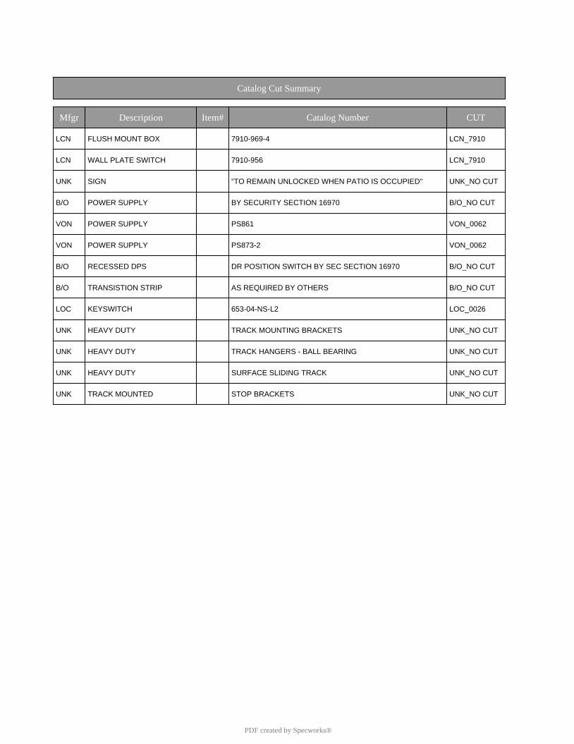
LCN FLUSH MOUNT BOX 7910-969-4 LCN_7910
LCN WALL PLATE SWITCH 7910-956 LCN_7910
UNK SIGN "TO REMAIN UNLOCKED WHEN PATIO IS OCCUPIED" UNK_NO CUT
B/O POWER SUPPLY BY SECURITY SECTION 16970 B/O_NO CUT
VON POWER SUPPLY PS861 VON_0062
VON POWER SUPPLY PS873-2 VON_0062
B/O RECESSED DPS DR POSITION SWITCH BY SEC SECTION 16970 B/O_NO CUT
B/O TRANSISTION STRIP AS REQUIRED BY OTHERS B/O_NO CUT
LOC KEYSWITCH 653-04-NS-L2 LOC_0026
UNK HEAVY DUTY TRACK MOUNTING BRACKETS UNK_NO CUT
UNK HEAVY DUTY TRACK HANGERS - BALL BEARING UNK_NO CUT
UNK HEAVY DUTY SURFACE SLIDING TRACK UNK_NO CUT
UNK TRACK MOUNTED STOP BRACKETS UNK_NO CUT
PDF created by Specworks®
PDF created by Specworks®
B6
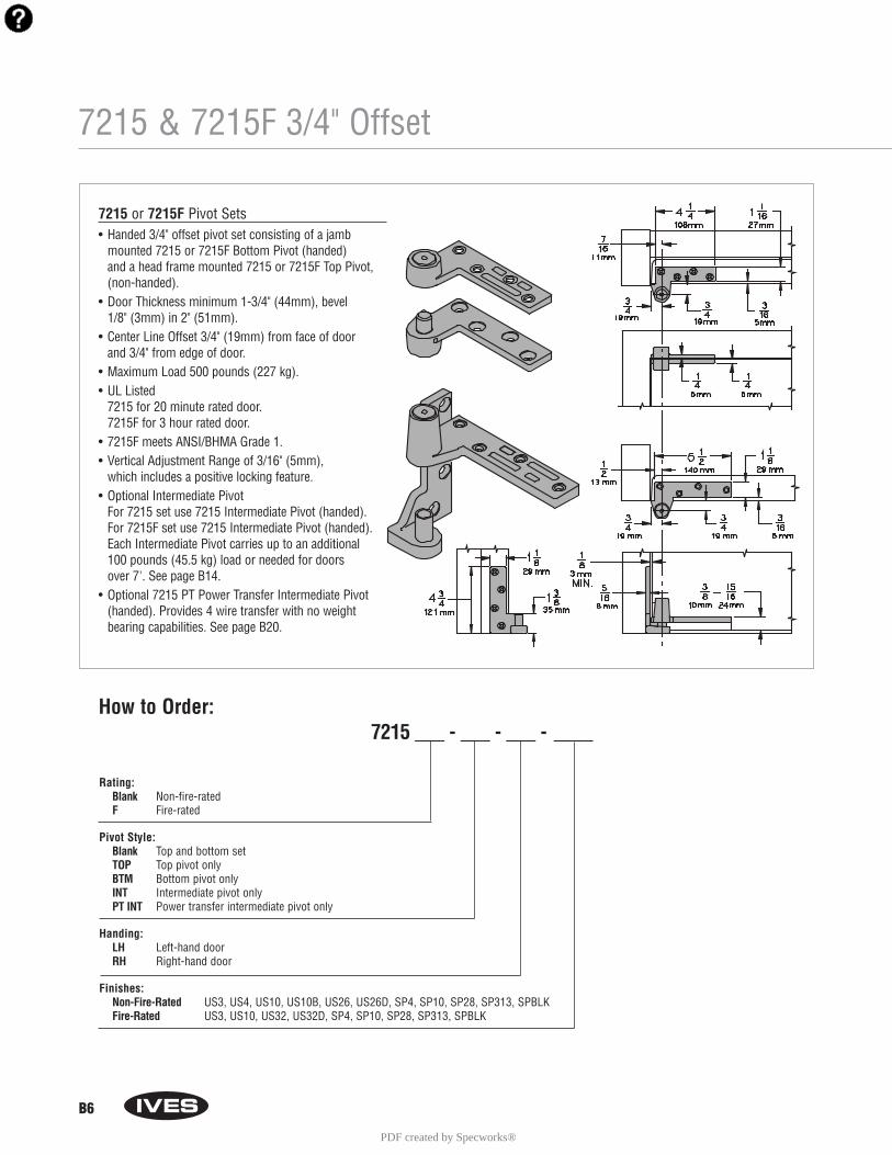
7215 & 7215F 3/4" Offset
7215 Pivot Set7215F Pivot Set
Rating: Blank Non-fire-rated F Fire-rated
Pivot Style: Blank Top and bottom setTOP Top pivot onlyBTM Bottom pivot onlyINT Intermediate pivot onlyPT INT Power transfer intermediate pivot only
Handing: LH Left-hand doorRH Right-hand door
Finishes: Non-Fire-Rated US3, US4, US10, US10B, US26, US26D, SP4, SP10, SP28, SP313, SPBLKFire-Rated US3, US10, US32, US32D, SP4, SP10, SP28, SP313, SPBLK
How to Order:7215 ___ - ___ - ___ - ____
7215 or 7215F Pivot Sets• Handed 3/4" offset pivot set consisting of a jamb
mounted 7215 or 7215F Bottom Pivot (handed) and a head frame mounted 7215 or 7215F Top Pivot,(non-handed).
• Door Thickness minimum 1-3/4" (44mm), bevel 1/8" (3mm) in 2" (51mm).
• Center Line Offset 3/4" (19mm) from face of door and 3/4" from edge of door.
• Maximum Load 500 pounds (227 kg).• UL Listed
7215 for 20 minute rated door.7215F for 3 hour rated door.
• 7215F meets ANSI/BHMA Grade 1.• Vertical Adjustment Range of 3/16" (5mm),
which includes a positive locking feature.• Optional Intermediate Pivot
For 7215 set use 7215 Intermediate Pivot (handed).For 7215F set use 7215 Intermediate Pivot (handed).Each Intermediate Pivot carries up to an additional 100 pounds (45.5 kg) load or needed for doors over 7'. See page B14.
• Optional 7215 PT Power Transfer Intermediate Pivot(handed). Provides 4 wire transfer with no weight bearing capabilities. See page B20.
PDF created by Specworks®

B10
7230F 3/4" Offset, Heavy Duty
How to Order:7230F - ____ - ____ - ____
Pivot Style:Blank Top and bottom setTOP Top pivot onlyBTM Bottom pivot onlyINT Intermediate pivot only
Handing: LH Left-hand doorRH Right-hand door
Finishes: US3, US10, US32, US32D, SP4, SP10, SP28, SP313, SPBLK
7230F Pivot Set7230F Heavy Duty Pivot Set• Non-handed 3/4" offset pivot set consisting of
a base plate mounted 7230F Bottom Pivot and a head frame mounted 7230F Top Pivot.
• Door Thickness minimum 1-3/4" (44mm), bevel 1/8" (3mm) in 2" (51mm).
• Center Line Offset 3/4" (19mm) from face of door and 3/4" from edge of door.
• Maximum Load 1000 pounds (455 kg).• Can be used on lead-lined doors.• UL Listed for 3 hour rated door.• Meets ANSI/BHMA Grade 1.• Vertical Adjustment Range of 3/16" (5mm),
which includes a positive locking feature.• Optional 7230F Intermediate Pivot (handed)
carries up to an additional 100 pounds (45.5 kg)load or needed for doors over 7'. See page B15.
PDF created by Specworks®
B14
7200 Series Intermediate Pivots
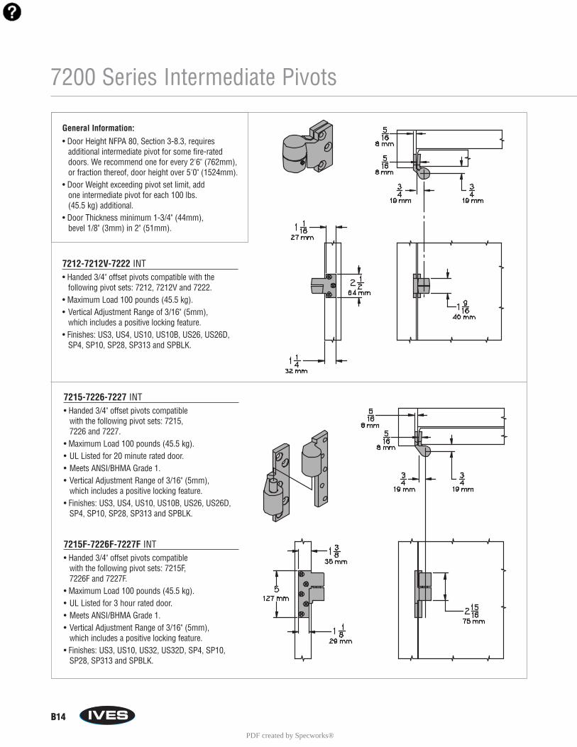
General Information:
• Door Height NFPA 80, Section 3-8.3, requires additional intermediate pivot for some fire-rateddoors. We recommend one for every 2'6" (762mm),or fraction thereof, door height over 5'0" (1524mm).
• Door Weight exceeding pivot set limit, add one intermediate pivot for each 100 lbs. (45.5 kg) additional.
• Door Thickness minimum 1-3/4" (44mm), bevel 1/8" (3mm) in 2" (51mm).
7212-7212V-7222 INT• Handed 3/4" offset pivots compatible with the
following pivot sets: 7212, 7212V and 7222.• Maximum Load 100 pounds (45.5 kg).• Vertical Adjustment Range of 3/16" (5mm),
which includes a positive locking feature.• Finishes: US3, US4, US10, US10B, US26, US26D,
SP4, SP10, SP28, SP313 and SPBLK.
15-7226-7227 INT15F-7226F-7227F INT
7215-7226-7227 INT• Handed 3/4" offset pivots compatible
with the following pivot sets: 7215, 7226 and 7227.
• Maximum Load 100 pounds (45.5 kg).• UL Listed for 20 minute rated door.• Meets ANSI/BHMA Grade 1.• Vertical Adjustment Range of 3/16" (5mm),
which includes a positive locking feature.• Finishes: US3, US4, US10, US10B, US26, US26D,
SP4, SP10, SP28, SP313 and SPBLK.
7215F-7226F-7227F INT• Handed 3/4" offset pivots compatible
with the following pivot sets: 7215F, 7226F and 7227F.
• Maximum Load 100 pounds (45.5 kg).• UL Listed for 3 hour rated door.• Meets ANSI/BHMA Grade 1.• Vertical Adjustment Range of 3/16" (5mm),
which includes a positive locking feature.• Finishes: US3, US10, US32, US32D, SP4, SP10,
SP28, SP313 and SPBLK.
PDF created by Specworks®
B15
7200 Series Intermediate Pivots
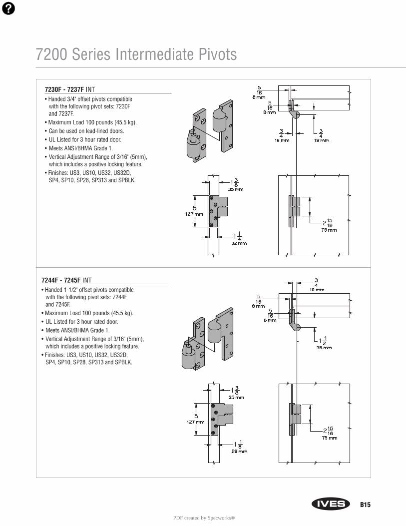
Intermediate Pivot7244F-7245F INT
30F-7237F INT
7244F - 7245F INT• Handed 1-1/2" offset pivots compatible
with the following pivot sets: 7244F and 7245F.
• Maximum Load 100 pounds (45.5 kg).• UL Listed for 3 hour rated door.• Meets ANSI/BHMA Grade 1.• Vertical Adjustment Range of 3/16" (5mm),
which includes a positive locking feature.• Finishes: US3, US10, US32, US32D,
SP4, SP10, SP28, SP313 and SPBLK.
7230F - 7237F INT• Handed 3/4" offset pivots compatible
with the following pivot sets: 7230F and 7237F.
• Maximum Load 100 pounds (45.5 kg).• Can be used on lead-lined doors.• UL Listed for 3 hour rated door.• Meets ANSI/BHMA Grade 1.• Vertical Adjustment Range of 3/16" (5mm),
which includes a positive locking feature.• Finishes: US3, US10, US32, US32D,
SP4, SP10, SP28, SP313 and SPBLK.
PDF created by Specworks®

B17
7255 & 7255J Center Hung Pivot Sets
Mounting: Blank Floor mounted bottom pivotJ Jamb mounted bottom pivot
Pivot Style: Blank Top and bottom setTOP Top pivot onlyBTM Bottom pivot only
Finishes: US3, US4, US10, US10B, US26, US26D, SP4, SP10, SP28, SP313, SPBLK
How to Order:7255 ___ - ___ - ___
7255 Pivot Set• Center hung pivot set consisting of base plate mounted 7255
Bottom Pivot and a head frame mounted 7255 Top Pivot.• Maximum Load 500 pounds (227 kg).• Door Thickness minimum 1-3/4" (44mm).• Radius Stop (A) to clear heel edge of door.• Pivot Distance (B) 1-3/4" (44mm) minimum from jamb to
centerline of pivot pin. Radius heel edge of door, 1-5/8"(41mm) minimum recommended.
• Clearance from bottom edge of door to the floor mountingsurface is adjustable from 3/16" (5mm) to 3/4" (19mm) byvarying the depth of the mortise (C) in the bottom rail of thedoor, refer to Table D. Over 3/4" (19mm) from the door tofloor mounting surface, consult factory.
• Meets ANSI/BHMA Grade 1.• Vertical Adjustment based on mortise preparation
in bottom rail of the door. Refer to Table D, pg. B16.
7255J Pivot Set• Center hung pivot set consisting of jamb mounted 7255J
Bottom Pivot and a head frame mounted 7255 Top Pivot.• Maximum Load 500 pounds (227 kg).• Door Thickness minimum 1-3/4" (44mm).• Radius Stop (A) to clear heel edge of door.• Pivot Distance (B) 1-3/4" (44mm) minimum from jamb to
centerline of pivot pin. Radius heel edge of door, 1-5/8"(41mm) minimum recommended.
• Clearance from bottom edge of door to the floor mountingsurface is adjustable from 3/16" (5mm) to 3/4" (19mm) byvarying the depth of the mortise (C) in the bottom rail of thedoor, refer to Table D. Over 3/4" (19mm) from the door tofloor mounting surface, consult factory.
• Meets ANSI/BHMA Grade 1.• Vertical Adjustment based on mortise preparation
in bottom rail of the door. Refer to Table D, pg. B16.
PDF created by Specworks®

B20
7200 Series Power Transfer Pivots
7215PT - 7226PT - 7227PT Pivot• Handed 3/4" intermediate offset pivot compatible
with 7210, 7220 or 7230 Series pivot sets.• Center Line Offset 3/4" (19mm) from face of door
and 3/4" from edge of door.• Power Transfer Pivot features two pairs of
conductors providing two separate, low voltage electric power and/or signal circuits between thedoor leaf and frame.
• Electrical Max. 1.0 Ampere @24V DC per pair of 28 gauge conductors.
• Non-Load Bearing Pivots.• Door Thickness minimum 1-3/4" (44mm), bevel
1/8" (3mm) in 2" (51 mm).• Raceway preparation required between the door leaf
area and door mounted electrical device. A racewayor other preparation is required to protect wiringrouted through all grout filled frames.
Options:
• 8 Wires
Model: 152627
Handing: LH Left-hand doorRH Right-hand door
Finishes:US3, US4, US10, US10B, US26, US26D, SP4, SP10, SP28, SP313, SPBLK
How to Order:72 ____ PT - ____ - _____
Power Transfer Intermediate Pivot7215-7226-7227 PT
PDF created by Specworks®
B21
91105F Pocket Pivot
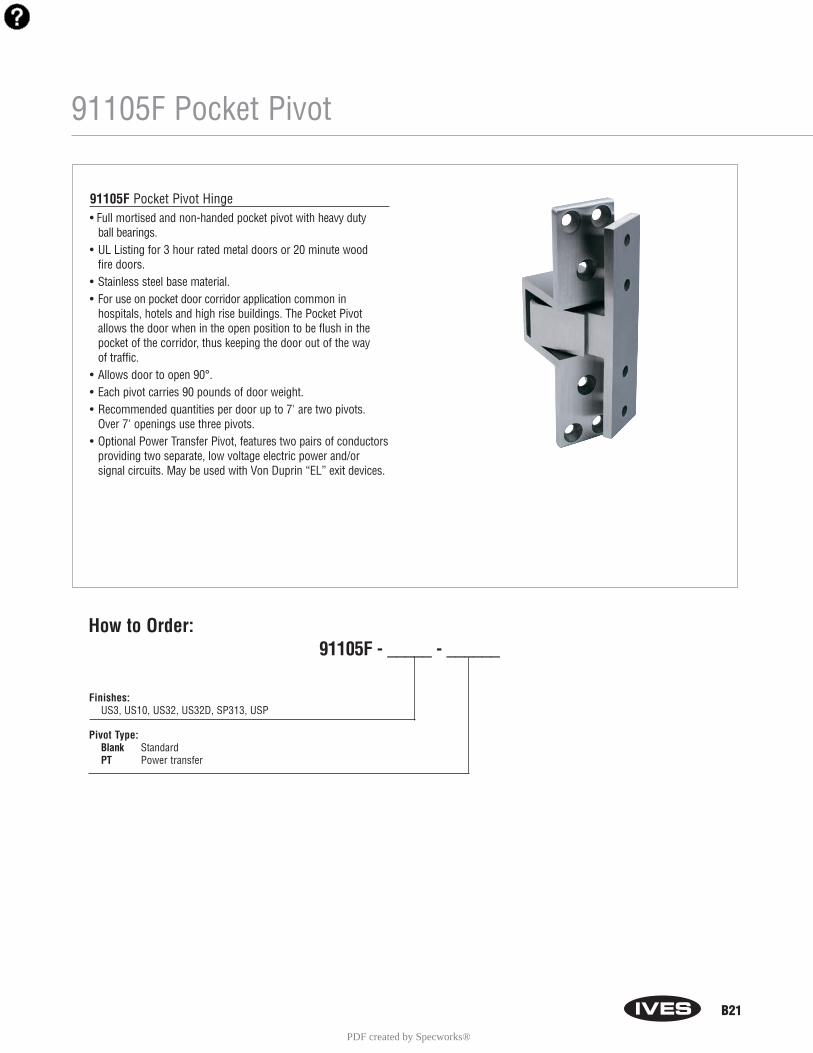
91105F Pocket Pivot Hinge• Full mortised and non-handed pocket pivot with heavy duty
ball bearings.• UL Listing for 3 hour rated metal doors or 20 minute wood
fire doors.• Stainless steel base material.• For use on pocket door corridor application common in
hospitals, hotels and high rise buildings. The Pocket Pivotallows the door when in the open position to be flush in thepocket of the corridor, thus keeping the door out of the way of traffic.
• Allows door to open 90°.• Each pivot carries 90 pounds of door weight.• Recommended quantities per door up to 7' are two pivots.
Over 7' openings use three pivots.• Optional Power Transfer Pivot, features two pairs of conductors
providing two separate, low voltage electric power and/or signal circuits. May be used with Von Duprin “EL” exit devices.
Finishes:US3, US10, US32, US32D, SP313, USP
Pivot Type: Blank StandardPT Power transfer
How to Order:91105F - _____ - ______
PDF created by Specworks®
B22
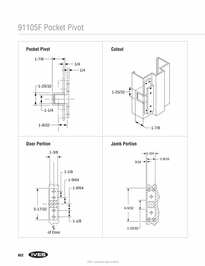
91105F Pocket Pivot
1-7/8
1-25/32
1-9/32
1/4
1-1/4
1/4
1-25/32
1-7/8
1-3/8
1-1/8
1-1/8
5-17/32
1-9/64
1-9/64
CLof Door
1-9/16
1-3/4
6-9/32
1-25/32
3/16
Door Portion Jamb Portion
Pocket Pivot Cutout
PDF created by Specworks®
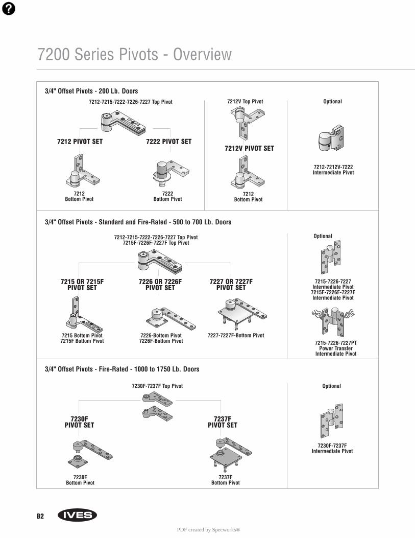
B2
7200 Series Pivots - Overview
3/4" Offset Pivots - 200 Lb. Doors
3/4" Offset Pivots - Standard and Fire-Rated - 500 to 700 Lb. Doors
3/4" Offset Pivots - Fire-Rated - 1000 to 1750 Lb. Doors
7212-7215-7222-7226-7227 Top Pivot
7212-7215-7222-7226-7227 Top Pivot7215F-7226F-7227F Top Pivot
7230F-7237F Top Pivot
7212 Bottom Pivot
7212V Top Pivot Optional
Optional
Optional
7212Bottom Pivot
7212V PIVOT SET
7212-7212V-7222Intermediate Pivot
7212 PIVOT SET 7222 PIVOT SET
7222Bottom Pivot
7215 Bottom Pivot7215F Bottom Pivot
7227-7227F-Bottom Pivot
7230FBottom Pivot
7237FBottom Pivot
7215-7226-7227PTPower Transfer
Intermediate Pivot
7230F-7237FIntermediate Pivot
7226-Bottom Pivot7226F-Bottom Pivot
7215 OR 7215FPIVOT SET
7230FPIVOT SET
7237FPIVOT SET
7227 OR 7227FPIVOT SET
7215-7226-7227 Intermediate Pivot
7215F-7226F-7227F Intermediate Pivot
7226 OR 7226FPIVOT SET
PDF created by Specworks®

B3
7200 Series Pivots - Overview
1-1/2" Offset Pivots - Fire-Rated - 400 to 500 Lb. Doors
Center Hung Pivots - 300 to 600 Lb. Doors
Center Hung Pivots - 1000 Lb. Doors
7253Bottom Pivot
7255Bottom Pivot
7255JBottom Pivot
7256Bottom Pivot
7253-7255-7255J-7256 Top Pivot
7259 Top Pivot
7259Bottom Pivot
7256PIVOT SET
7255JPIVOT SET
7255PIVOT SET
7253PIVOT SET
7244F-7245FTop Pivot
7244F Bottom Pivot
Optional
7244F-7245FIntermediate Pivot
7244F PIVOT SET 7245F PIVOT SET
7245FBottom Pivot
7259 PIVOT SET
PDF created by Specworks®

B4
7200 Series Pivot Selection ChartPivot UL Top Bottom Bottom Pivot Recommended 3/4" 1-1/2" Center Max Door HandedSet Rating Pivot Pivot Mounting Intermediate Pivot Offset Offset Hung Weight
7212 None 7212-7215-7222-7226-7227 7212 BTM Jamb 7212-7212V-7222 Yes 200 YesTOP Mounted INT
7212V None 7212V 7212 BTM Jamb 7212-7212V-7222 Yes 200 YesTOP Mounted INT
7215 20 min 7212-7215-7222-7226-7227 7215 BTM Jamb 7215-7226-7227 Yes 500 YesTOP Mounted INT
7215F 3 hr 7215F-7226F-7227F 7215F BTM Jamb 7215F-7226F-7227F Yes 500 YesTOP Mounted INT
7222 None 7212-7215-7222-7226-7227 7222 BTM Floor 7212-7212V-7222 Yes 200 YesTOP Mounted INT
7226 20 min 7212-7215-7222-7226-7227 7226 BTM Floor 7215-7226-7227 Yes 600 NoTOP Mounted INT
7226F 3 hr 7215F-7226F-7227F 7226F BTM Floor 7215F-7226F-7227F Yes 600 NoTOP Mounted INT
7227 20 min 7212-7215-7222-7226-7227 7227 BTM Mortised 7215-7226-7227 Yes 700 NoTOP Cement Case INT
7227F 3 hr 7215F-7226F-7227F 7227 BTM Mortised 7215F-7226F-7227F Yes 700 NoTOP Cement Case INT
7230F 3 hr 7230F-7237F 7230F BTM Floor 7230F-7237F Yes 1000 NoTOP Mounted INT
7237F 3 hr 7230F-7237F 7237F BTM Mortised 7230F-7237F Yes 1750 NoTOP Cement Case INT
7244F 3 hr 7244F-7245F 7244F BTM Floor 7244F-7245F Yes 400 NoTOP Mounted INT
7245F 3 hr 7244F-7245F 7245F BTM Mortised 7244F-7245F Yes 500 NoTOP Cement Case INT
7253 None 7253-7255-7255J-7256 7253 BTM Floor None Yes 300 NoTOP Mounted
7255 None 7253-7255-7255J-7256 7255 BTM Floor None Yes 500 NoTOP Mounted
7255J None 7253-7255-7255J-7256 7255J BTM Jamb None Yes 500 NoTOP Mounted
7256 None 7253-7255-7255J-7256 7256 BTM Mortised None Yes 600 NoTOP Cement Case
7259 None 7259 7259 BTM Mortised None Yes 1000 NoTOP Cement Case
PDF created by Specworks®

B5
7212V Pivot Set
7212 & 7212V 3/4" Offset
7212 Pivot Set• Handed 3/4" offset pivot set consisting of a jamb
mounted 7212 Bottom Pivot (handed), and a headframe mounted 7212 Top Pivot (non-handed).
• Door Thickness minimum 1-3/4" (44mm), bevel 1/8" (3mm) in 2" (51mm).
• Center Line Offset 3/4" (19mm) from face of door and 3/4" from edge of door.
• Maximum Load 200 pounds (91 kg).• Vertical Adjustment Range of 3/16" (5mm),
which includes a positive locking feature.• Optional 7212 Intermediate Pivot (handed) carries
up to an additional 100 pounds (45.5 kg) load or needed for doors over 7'. See page B14.
7212V Pivot Set• Handed 3/4" offset pivot set consisting of a jamb
mounted 7212 Bottom Pivot (handed), and a jambmounted 7212V Top Pivot (handed).
• Door Thickness minimum 1-3/4" (44mm), bevel1/8" (3mm) in 2" (51mm).
• Center Line Offset 3/4" (19mm) from face of door and 3/4" from edge of door.
• Maximum Load 200 pounds (91 kg).• Vertical Adjustment Range of 3/16" (5mm),
which includes a positive locking feature.• Optional 7212 intermediate Pivot (handed)
carries up to an additional 100 pounds (45.5 kg)load or needed for doors over 7'. See page B14.
Mounting Type: Blank Head frame mounted to pivotV Jamb mounted top pivot
Pivot Style: Blank Top and bottom setTOP Top pivot onlyBTM Bottom pivot onlyINT Intermediate pivot
Handing:LH Left-hand doorRH Right-hand door
Finishes: US3, US4, US10, US10B, US26, US26D, SP4, SP10, SP28, SP313, SPBLK
How to Order: 7212 ___ - ___ - ___ - _____
PDF created by Specworks®
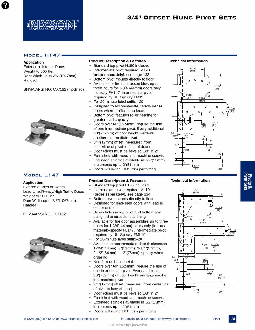
125In USA: (800) 457-5670 or www.rixsondoorcontrols.com In Canada: (905) 564-5854 or www.yalecorbin.on.ca 04/01
3/4" Offset Hung Pivot Sets
Product Description & Features• Standard top pivot H180 included• Intermediate pivot required: M190
(order separately), see page 133• Bottom pivot mounts directly to floor• Available for fire door assemblies up to
three hours for 1-3/4"(44mm) doors only–specify FH147. Intermediate pivotrequired by UL. Specify FM19
• For 20-minute label suffix –20• Designed to accommodate narrow dense
doors where traffic is moderate• Bottom pivot features roller bearing for
greater load capacity• Doors over 60"(1524mm) require the use
of one intermediate pivot. Every additional30"(762mm) of door height warrantsanother intermediate pivot
• 3/4"(19mm) offset (measured fromcenterline of pivot to face of door)
• Door edges must be beveled 1/8" in 2"• Furnished with wood and machine screws• Extended spindles available in 1/2"(13mm)
increments up to 2"(51mm)• Doors will swing 180°, trim permitting
Model L147
ApplicationExterior or Interior Doors Lead Lined/Heavy/High Traffic DoorsWeight to 1000 lbs.Door Width up to 3'6"(1067mm)Handed
BHMA/ANSI NO: C07162
Technical InformationProduct Description & Features• Standard top pivot L180 included• Intermediate pivot required: ML19
(order separately), see page 134• Bottom pivot mounts directly to floor• Designed for lead-lined doors with lead in
center of door• Screw holes in top pivot and bottom arm
designed to straddle lead lining• Available for fire door assemblies up to three
hours for 1-3/4"(44mm) doors only (ferrousmaterial)–specify FL147. Intermediate pivotrequired by UL. Specify FML19
• For 20-minute label suffix–20• Available to accommodate door thicknesses
1-3/4"(44mm), 2"(51mm), 2-1/4"(57mm),2-1/2"(64mm), or 3"(76mm)–specify whenordering
• Non-ferrous base metal• Doors over 60"(1524mm) require the use of
one intermediate pivot. Every additional30"(762mm) of door height warrants anotherintermediate pivot
• 3/4"(19mm) offset (measured from centerlineof pivot to face of door)
• Door edges must be beveled 1/8" in 2"• Furnished with wood and machine screws• Extended spindles available in 1/2"(13mm)
increments up to 2"(51mm)• Doors will swing 180°, trim permitting
Model H147
ApplicationExterior or Interior DoorsWeight to 800 lbs.Door Width up to 3'6"(1067mm)Handed
BHMA/ANSI NO: C07162 (modified)
Technical Information
Pivots & Pivot Sets
PDF created by Specworks®

138 In USA: (800) 457-5670 or www.rixsondoorcontrols.com In Canada: (905) 564-5854 or www.yalecorbin.on.ca 04/01
Pivo
ts &
Pi
vot S
ets
Center Hung Pivot Sets
Model 117-3/4
ApplicationExterior or Interior DoorsWeight to 600 lbs.Door Sizes up to 4'0"x 8'6" (1219 x 2591mm)Non-Handed
BHMA/ANSI NO: C07021 (modified)
Product Description & Features• Standard top pivot 340 included• Pivot set is fully concealed• Bottom pivot is mortised into floor • Heavy-duty bearings• All center hung pivot sets are double-
acting unless stopped by some means onthe door frame
• Not allowed for use on labeled doors andframes
• Available with longer spindles in1/2"(13mm) increments up to 2"(51mm)
• Pivot point centered in thickness of door• Door must have radius on pivot edge• Furnished with wood and machine screws• Doors do not return to center• For doors over 8'6" in height substitute
340 top pivot with 345 (see page 141)
Technical Information
Model H117-3/4
ApplicationExterior or Interior DoorsWeight to 1,000 lbs.Door Sizes up to 4'0"x 8'6" (1219 x 2591mm)Non-Handed
BHMA/ANSI NO: C07011
Technical InformationProduct Description & Features• Standard top pivot H340 included• Pivot set is fully concealed• Bottom pivot is mortised into floor• Standard set is equipped with end load
arm for 2"(51mm) thick doors• Extra heavy-duty bearings• All center hung pivot sets are double-
acting unless stopped by some means onthe door frame
• Not allowed for use on labeled doors andframes
• Available with longer spindles in1/2"(13mm) increments up to 2"(51mm)
• Pivot point centered in thickness of door• Door must have radius on pivot edge• Furnished with wood and machine screws• Doors do not return to center
PDF created by Specworks®
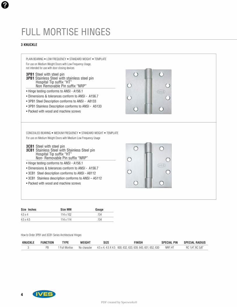
4
FULL MORTISE HINGES
3PB1 Steel with steel pin3PB1 Stainless Steel with stainless steel pin
Hospital Tip suffix “HT”Non Removable Pin suffix “NRP”
• Hinge testing conforms to ANSI - A156.1 • Dimensions & tolerances conform to ANSI - A156.7• 3PB1 Steel Description conforms to ANSI - A8133• 3PB1 Stainless Description conforms to ANSI - A5133• Packed with wood and machine screws
3 KNUCKLE
Size Inches Size MM Gauge
4.5 x 4 114 x 102 .134
4.5 x 4.5 114 x 114 .134
KNUCKLE FUNCTION TYPE WEIGHT SIZE FINISH SPECIAL PIN SPECIAL RADIUS
3 PB 1 Full Mortise No character 4.5 x 4, 4.5 X 4.5 600, 632, 633, 639, 643, 651, 652, 630 NRP, HT RC 1/4”,RC 5/8”
PLAIN BEARING • LOW FREQUENCY • STANDARD WEIGHT • TEMPLATE
For use on Medium Weight Doors with Low Frequency Usage, not intended for use with door closing devices
3CB1 Steel with steel pin3CB1 Stainless Steel with Stainless Steel pin
Hospital Tip suffix “HT”Non- Removable Pin suffix “NRP”
• Hinge testing conforms to ANSI - A156.1 • Dimensions & tolerances conform to ANSI - A156.7• 3CB1 Steel description conforms to ANSI - A8112• 3CB1 Stainless description conforms to ANSI – A5112• Packed with wood and machine screws
CONCEALED BEARING • MEDIUM FREQUENCY • STANDARD WEIGHT • TEMPLATE
For use on Medium Weight Doors with Medium Low Frequency Usage
How to Order 3PB1 and 3CB1 Series Architectural Hinges
PDF created by Specworks®
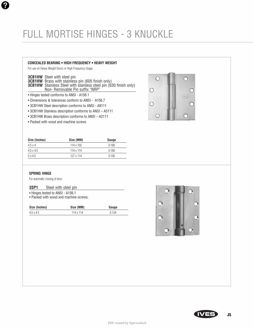
J5
FULL MORTISE HINGES - 3 KNUCKLE
3CB1HW Steel with steel pin3CB1HW Brass with stainless pin (605 finish only)3CB1HW Stainless Steel with stainless steel pin (630 finish only)
Non- Removable Pin suffix “NRP”• Hinges tested conforms to ANSI - A156.1 • Dimensions & tolerances conform to ANSI - A156.7• 3CB1HW Steel description conforms to ANSI - A8111• 3CB1HW Stainless description conforms to ANSI – A5111• 3CB1HW Brass description conforms to ANSI – A2111• Packed with wood and machine screws
CONCEALED BEARING • HIGH FREQUENCY • HEAVY WEIGHT For use on Heavy Weight Doors or High Frequency Usage
Size (Inches) Size (MM) Gauge
4.5 x 4 114 x 102 0.180
4.5 x 4.5 114 x 114 0.180
5 x 4.5 127 x 114 0.190
3SP1 Steel with steel pin• Hinges tested to ANSI - A156.1 • Packed with wood and machine screws.
SPRING HINGEFor automatic closing of door.
Size (Inches) Size (MM) Gauge
4.5 x 4.5 114 x 114 0.134
PDF created by Specworks®
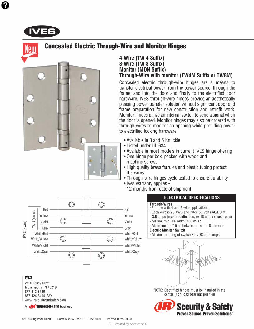
4-Wire (TW 4 Suffix)8-Wire (TW 8 Suffix)Monitor (MON Suffix)Through-Wire with monitor (TW4M Suffix or TW8M)Concealed electric through-wire hinges are a means to transfer electrical power from the power source, through theframe, and into the door and finally to the electrified doorhardware. IVES through-wire hinges provide an aestheticallypleasing power transfer solution without significant door andframe preparation for new construction and retrofit work.Monitor hinges utilize an internal switch to send a signal whenthe door is opened. Monitor hinges may also be ordered withthrough-wires to monitor an opening while providing powerto electrified locking hardware.
• Available in 3 and 5 Knuckle• Listed under UL 634• Available in most models in current IVES hinge offering• One hinge per box, packed with wood and
machine screws• High quality brass ferrules and plastic tubing protect
the wires• Through-wire hinges cycle tested to ensure durability• Ives warranty applies -
12 months from date of shipment
IVES2720 Tobey DriveIndianapolis, IN 46219877-613-8766877-424-8494 FAXwww.irsecurityandsafety.com
Concealed Electric Through-Wire and Monitor Hinges
© 2004 Ingersoll-Rand Form IV-2067 Ver. 2 Rev. 8//04 Printed in the U.S.A.
Red
Yellow
Violet
GrayWhite/Red
TW-8
(8 w
ire)
TW-4
(4 w
ire)
White/Yellow
White/Violet
White/Gray
Red
Yellow
Violet
GrayWhite/RedWhite/Yellow
White/Violet
White/Gray
ELECTRICAL SPECIFICATIONSThrough-Wires- For use with 4 and 8 wire applications- Each wire is 28 AWG and rated 50 Volts AC/DC at
3.5 amps (max.) continuous, or 16 amps (max.) pulse.- Maximum pulse width: 400 msec.- Minimum “off” time between pulses: 10 secondsElectric Monitor Switch- Maximum rating of switch 30 VDC at .5 amps
NOTE: Electrified hinges must be installed in the center (non-load bearing) position
PDF created by Specworks®
A1
Automatic Flush Bolts - Metal Doors
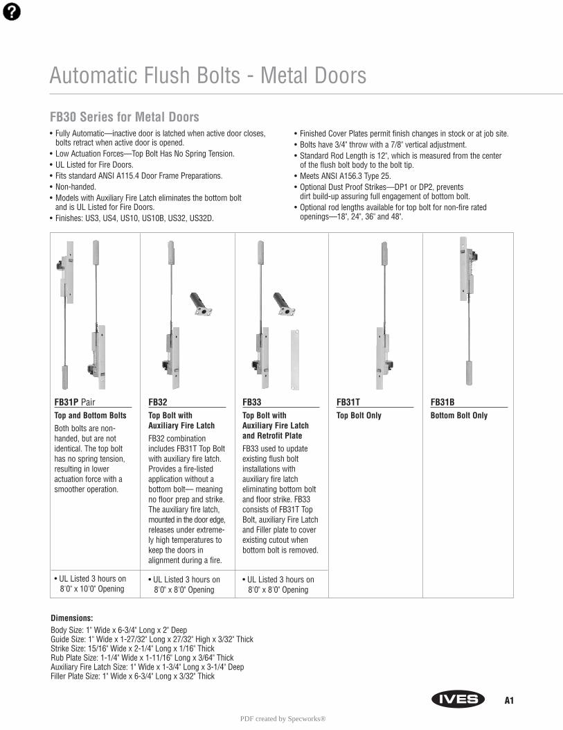
FB30 Series for Metal Doors• Fully Automatic—inactive door is latched when active door closes,
bolts retract when active door is opened.• Low Actuation Forces—Top Bolt Has No Spring Tension.• UL Listed for Fire Doors.• Fits standard ANSI A115.4 Door Frame Preparations.• Non-handed.• Models with Auxiliary Fire Latch eliminates the bottom bolt
and is UL Listed for Fire Doors.• Finishes: US3, US4, US10, US10B, US32, US32D.
• Finished Cover Plates permit finish changes in stock or at job site.• Bolts have 3/4" throw with a 7/8" vertical adjustment.• Standard Rod Length is 12", which is measured from the center
of the flush bolt body to the bolt tip. • Meets ANSI A156.3 Type 25.• Optional Dust Proof Strikes—DP1 or DP2, prevents
dirt build-up assuring full engagement of bottom bolt.• Optional rod lengths available for top bolt for non-fire rated
openings—18", 24", 36" and 48".
FB31P PairTop and Bottom Bolts
Both bolts are non-handed, but are notidentical. The top bolthas no spring tension,resulting in lower actuation force with asmoother operation.
• UL Listed 3 hours on8'0" x 10'0" Opening
FB32Top Bolt with Auxiliary Fire Latch
FB32 combinationincludes FB31T Top Boltwith auxiliary fire latch.Provides a fire-listedapplication without abottom bolt— meaningno floor prep and strike.The auxiliary fire latch,mounted in the door edge,releases under extreme-ly high temperatures tokeep the doors in alignment during a fire.
• UL Listed 3 hours on8'0" x 8'0" Opening
FB33Top Bolt with Auxiliary Fire Latch and Retrofit Plate
FB33 used to updateexisting flush boltinstallations with auxiliary fire latch eliminating bottom boltand floor strike. FB33consists of FB31T TopBolt, auxiliary Fire Latchand Filler plate to coverexisting cutout whenbottom bolt is removed.
• UL Listed 3 hours on8'0" x 8'0" Opening
FB31TTop Bolt Only
FB31BBottom Bolt Only
Dimensions:Body Size: 1" Wide x 6-3/4" Long x 2" DeepGuide Size: 1" Wide x 1-27/32" Long x 27/32" High x 3/32" ThickStrike Size: 15/16" Wide x 2-1/4" Long x 1/16" ThickRub Plate Size: 1-1/4" Wide x 1-11/16" Long x 3/64" Thick Auxiliary Fire Latch Size: 1" Wide x 1-3/4" Long x 3-1/4" DeepFiller Plate Size: 1" Wide x 6-3/4" Long x 3/32" Thick
PDF created by Specworks®
A2
Automatic Flush Bolts - Wood Doors
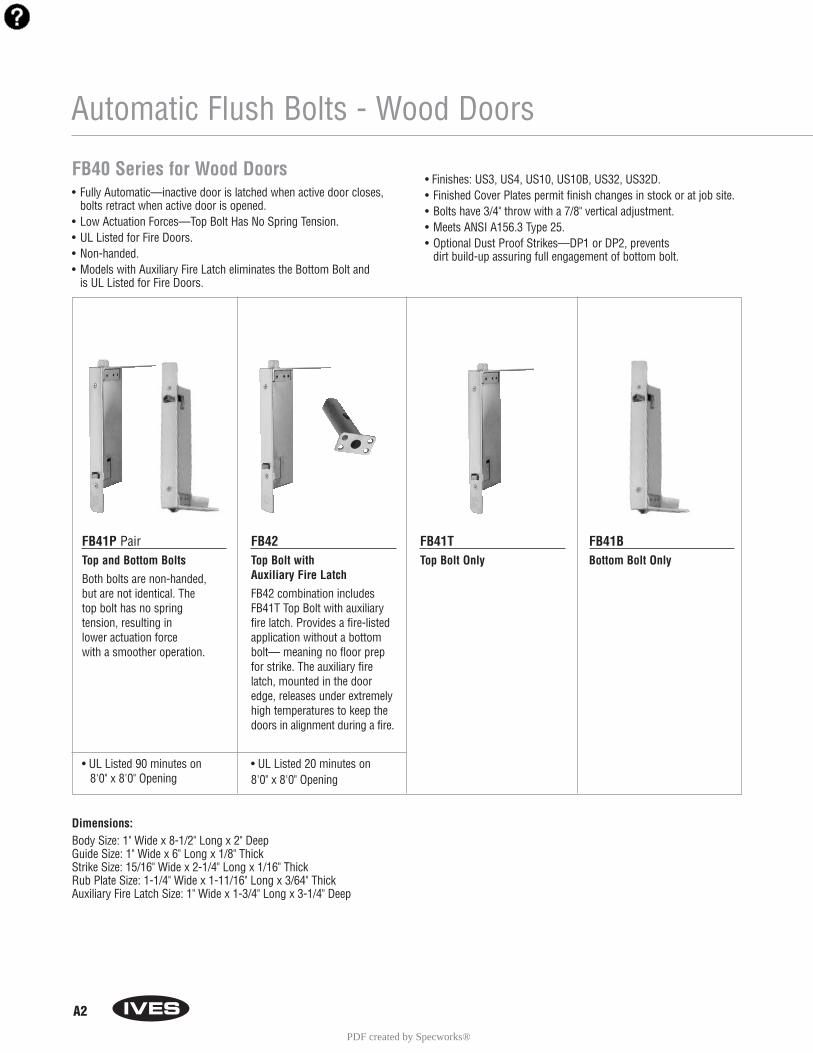
FB40 Series for Wood Doors• Fully Automatic—inactive door is latched when active door closes,
bolts retract when active door is opened.• Low Actuation Forces—Top Bolt Has No Spring Tension.• UL Listed for Fire Doors.• Non-handed.• Models with Auxiliary Fire Latch eliminates the Bottom Bolt and
is UL Listed for Fire Doors.
• Finishes: US3, US4, US10, US10B, US32, US32D.• Finished Cover Plates permit finish changes in stock or at job site.• Bolts have 3/4" throw with a 7/8" vertical adjustment.• Meets ANSI A156.3 Type 25.• Optional Dust Proof Strikes—DP1 or DP2, prevents
dirt build-up assuring full engagement of bottom bolt.
FB41P PairTop and Bottom Bolts
Both bolts are non-handed, but are not identical. The top bolt has no spring tension, resulting in lower actuation forcewith a smoother operation.
• UL Listed 90 minutes on 8'0" x 8'0" Opening
FB42Top Bolt with Auxiliary Fire Latch
FB42 combination includesFB41T Top Bolt with auxiliaryfire latch. Provides a fire-listed application without a bottombolt— meaning no floor prepfor strike. The auxiliary firelatch, mounted in the dooredge, releases under extremelyhigh temperatures to keep thedoors in alignment during a fire.
• UL Listed 20 minutes on 8'0" x 8'0" Opening
FB41TTop Bolt Only
FB41BBottom Bolt Only
Dimensions:Body Size: 1" Wide x 8-1/2" Long x 2" DeepGuide Size: 1" Wide x 6" Long x 1/8" ThickStrike Size: 15/16" Wide x 2-1/4" Long x 1/16" ThickRub Plate Size: 1-1/4" Wide x 1-11/16" Long x 3/64" ThickAuxiliary Fire Latch Size: 1" Wide x 1-3/4" Long x 3-1/4" Deep
PDF created by Specworks®
A5
Manual Flush Bolts - Metal Doors
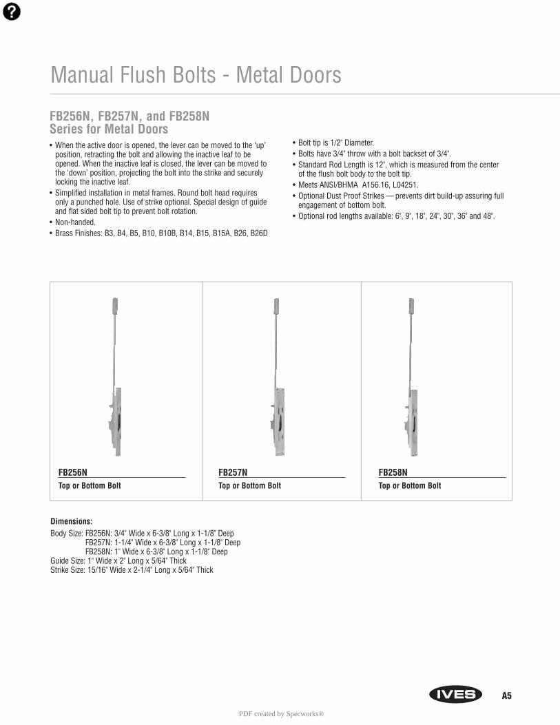
FB256N, FB257N, and FB258NSeries for Metal Doors• When the active door is opened, the lever can be moved to the ‘up’
position, retracting the bolt and allowing the inactive leaf to beopened. When the inactive leaf is closed, the lever can be moved tothe ‘down’ position, projecting the bolt into the strike and securelylocking the inactive leaf.
• Simplified installation in metal frames. Round bolt head requiresonly a punched hole. Use of strike optional. Special design of guideand flat sided bolt tip to prevent bolt rotation.
• Non-handed.• Brass Finishes: B3, B4, B5, B10, B10B, B14, B15, B15A, B26, B26D
• Bolt tip is 1/2" Diameter.• Bolts have 3/4" throw with a bolt backset of 3/4".• Standard Rod Length is 12", which is measured from the center
of the flush bolt body to the bolt tip. • Meets ANSI/BHMA A156.16, L04251.• Optional Dust Proof Strikes — prevents dirt build-up assuring full
engagement of bottom bolt.• Optional rod lengths available: 6", 9", 18", 24", 30", 36" and 48".
FB256NTop or Bottom Bolt
FB257NTop or Bottom Bolt
FB258NTop or Bottom Bolt
Dimensions:Body Size: FB256N: 3/4" Wide x 6-3/8" Long x 1-1/8" Deep
FB257N: 1-1/4" Wide x 6-3/8" Long x 1-1/8" DeepFB258N: 1" Wide x 6-3/8" Long x 1-1/8" Deep
Guide Size: 1" Wide x 2" Long x 5/64" ThickStrike Size: 15/16" Wide x 2-1/4" Long x 5/64" Thick
PDF created by Specworks®

A6
FB358 Series for Wood Doors• When the active door is opened, the lever can be moved to the
‘up’ position, retracting the bolt and allowing the inactive leaf to beopened. When the inactive leaf is closed, the lever can be moved tothe ‘down’ position, projecting the bolt into the strike and securelylocking the inactive leaf.
• Reduces installation costs; requires only simple router mortise at top and bottom corners of doors.
• Door strength and rigidity maintained by tying door faces to reinforcing extensions on guide with machine screws and bearing washers.
• UL Listed for Fire Doors.• Non-handed.• Brass Finishes: B3, B4, B5, B10, B10B, B14, B15, B15A, B26, B26D.• Bolts have 3/4" throw with a 7/8" vertical adjustment.• Meets ANSI/BHMA A156.16, L04261.• Optional Dust Proof Strikes—DP1 or DP2, prevents dirt
build-up assuring full engagement of bottom bolt.• Not available for rabbeted door installations.
FB358Top or Bottom Bolts
• UL Listed 90 minutes on 8'0" x 10'0" Opening
Manual Flush Bolts - Wood Doors
Dimensions:Body Size: 1" Wide x 6-3/4" Long x 1-3/8" DeepGuide Size: 1" Wide x 2-1/2" Long x 5/64" ThickStrike Size: 15/16" Wide x 2-1/4" Long x 5/64" Thick
PDF created by Specworks®

A7
Manual Flush Bolts - Metal Doors
FB457 and FB457N Series for Metal Doors• When the active door is opened, the lever can be moved to the
‘up’ position, retracting the bolt and allowing the inactive leaf to beopened. When the inactive leaf is closed, the lever can be moved tothe ‘down’ position, projecting the bolt into the strike and securelylocking the inactive leaf.
• Simplified installation in metal frames. Round bolt head requiresonly a punched hole. Use of strike optional. Special design of guideand flat sided bolt tip to prevent bolt rotation.
• Non-handed.• FB457 UL Listed for Fire Doors.• FB457N not UL Listed for Fire Doors.• Brass Finishes: B3, B4, B5, B10, B10B, B14, B15, B15A, B26,
B26D.
• Bolt tip is 1/2" Diameter.• Bolts have 3/4" throw with a bolt backset of 3/4".• Standard Rod Length is 12", which is measured from the center
of the flush bolt body to the bolt tip. • Meets ANSI/BHMA A156.16, L04251.• Optional Dust Proof Strikes — prevents dirt build-up assuring full
engagement of bottom bolt.• Optional rod lengths available for FB457: 6", 9", 18" and 24".• Optional rod lengths available for FB457N: 6", 9", 18", 24", 30",
36" and 48".
FB457Top or Bottom Bolt
• UL Listed 3 hours on 8'0" x 10'0" Opening
FB457NTop or Bottom Bolt
Dimensions:Body Size: 1-1/4" Wide x 6-3/4" Long x 1-1/8" DeepGuide Size: 1" Wide x 2" Long x 5/64" ThickStrike Size: 15/16" Wide x 2-1/4" Long x 5/64" Thick
PDF created by Specworks®

A8
Manual Flush Bolts - Metal Doors
FB458, FB458N and FB0458N Series for Metal Doors• When the active door is opened, the lever can be moved to the ‘up’
position, retracting the bolt and allowing the inactive leaf to beopened. When the inactive leaf is closed, the lever can be moved tothe ‘down’ position, projecting the bolt into the strike and securelylocking the inactive leaf.
• Simplified installation in metal frames. Round bolt head requiresonly a punched hole. Use of strike optional. Special design of guideand flat sided bolt tip to prevent bolt rotation.
• FB458 UL Listed for Fire Doors.• FB458N and FB0458N not UL Listed for Fire Doors.• FB0458N features 1/4" radius corners on body.• Non-handed.
• Brass Finishes: B3, B4, B5, B10, B10B, B14, B15, B15A, B26, B26D.• Bolt tip is 1/2" diameter.• Bolts have 3/4" throw with a bolt backset of 3/4".• Standard Rod Length is 12", which is measured from the center
of the flush bolt body to the bolt tip. • Meets ANSI/BHMA A156.16, L04251.• Optional Dust Proof Strikes— prevents dirt build-up assuring full
engagement of bottom bolt.• Optional Rod Lengths available for FB458: 6", 9", 18" and 24".• Optional Rod Lengths available for FB458N and FB0458N: 6", 9", 18",
24", 30", 36" and 48".
FB458Top or Bottom Bolt
• UL Listed 3 hours on 8'0" x 10'0" Opening
FB458NTop or Bottom Bolt
FB0458NTop or Bottom Bolt
Dimensions:Body Size: 1" Wide x 6-3/4" Long x 1-1/8" DeepGuide Size: 1" Wide x 2" Long x 5/64" ThickStrike Size: 15/16" Wide x 2-1/4" Long x 5/64" Thick
PDF created by Specworks®
A9
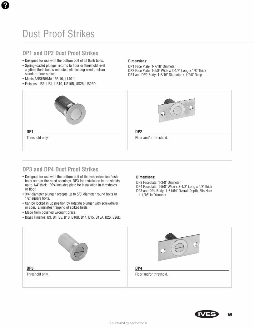
Dust Proof Strikes
DP1 and DP2 Dust Proof Strikes• Designed for use with the bottom bolt of all flush bolts. • Spring-loaded plunger returns to floor or threshold level
anytime flush bolt is retracted, eliminating need to clean standard floor strikes.
• Meets ANSI/BHMA 156.16, L14011.• Finishes: US3, US4, US10, US10B, US26, US26D.
Dimensions:DP1 Face Plate: 1-7/16" DiameterDP2 Face Plate: 1-5/8" Wide x 3-1/2" Long x 1/8" ThickDP1 and DP2 Body: 1-3/16" Diameter x 1-7/8" Deep
DP1Threshold only.
DP2Floor and/or threshold.
DP3 and DP4 Dust Proof Strikes• Designed for use with the bottom bolt of the Ives extension flush
bolts on non-fire rated openings. DP3 for installation in thresholdsup to 1/4" thick. DP4 includes plate for installation in thresholds or floor.
• 3/4" diameter plunger accepts up to 5/8" diameter round bolts or1/2" square bolts.
• Can be locked in up position by rotating plunger with screwdriver or coin. Eliminates trapping of spiked heels.
• Made from polished wrought brass.• Brass Finishes: B3, B4, B5, B10, B10B, B14, B15, B15A, B26, B26D.
Dimensions:DP3 Faceplate: 1-3/8" DiameterDP4 Faceplate: 1-5/8" Wide x 3-1/2" Long x 1/8" thickDP3 and DP4 Body: 1-61/64" Overall Depth, Fits Hole
1-1/16" in Diameter
DP3Threshold only.
DP4Floor and/or threshold.
PDF created by Specworks®
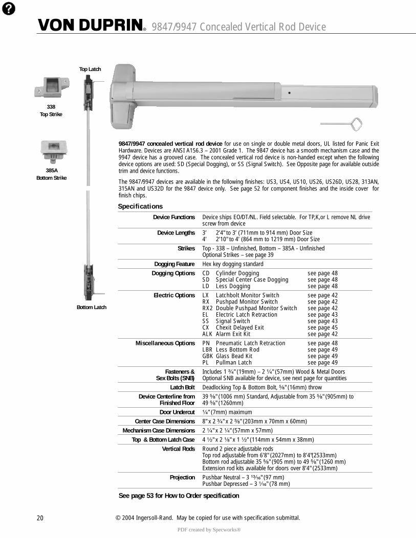
9847/9947 Concealed Vertical Rod Device
20 © 2004 Ingersoll-Rand. May be copied for use with specification submittal.
9847/9947 concealed vertical rod device for use on single or double metal doors, UL listed for Panic ExitHardware. Devices are ANSI A156.3 – 2001 Grade 1. The 9847 device has a smooth mechanism case and the9947 device has a grooved case. The concealed vertical rod device is non-handed except when the followingdevice options are used: SD (Special Dogging), or SS (Signal Switch). See Opposite page for available outsidetrim and device functions.
The 9847/9947 devices are available in the following finishes: US3, US4, US10, US26, US26D, US28, 313AN,315AN and US32D for the 9847 device only. See page 52 for component finishes and the inside cover forfinish chips.
See page 53 for How to Order specification
Top Latch
Bottom Latch
385A Bottom Strike
338 Top Strike
SpecificationsDevice Functions Device ships EO/DT/NL. Field selectable. For TP,K,or L remove NL drive
screw from deviceDevice Lengths 3’ 2’4" to 3’ (711mm to 914 mm) Door Size
4’ 2’10" to 4’ (864 mm to 1219 mm) Door SizeStrikes Top - 338 – Unfinished, Bottom – 385A - Unfinished
Optional Strikes – see page 39Dogging Feature Hex key dogging standard
Dogging Options CD Cylinder Dogging see page 48 SD Special Center Case Dogging see page 48 LD Less Dogging see page 48
Electric Options LX Latchbolt Monitor Switch see page 42 RX Pushpad Monitor Switch see page 42 RX2 Double Pushpad Monitor Switch see page 42EL Electric Latch Retraction see page 43 SS Signal Switch see page 43 CX Chexit Delayed Exit see page 45ALK Alarm Exit Kit see page 42
Miscellaneous Options PN Pneumatic Latch Retraction see page 48 LBR Less Bottom Rod see page 49 GBK Glass Bead Kit see page 49PL Pullman Latch see page 49
Fasteners & Includes 1 ³�₄" (19mm) – 2 ¹�₄" (57mm) Wood & Metal DoorsSex Bolts (SNB) Optional SNB available for device, see next page for quantities
Latch Bolt Deadlocking Top & Bottom Bolt, ⁵�₈" (16mm) throw Device Centerline from 39 ⁵�₈" (1006 mm) Standard, Adjustable from 35 ⁵�₈" (905mm) to
Finished Floor 49 ⁵�₈" (1260mm)Door Undercut ¹�₄" (7mm) maximum
Center Case Dimensions 8" x 2 ³�₄" x 2 ³�₈" (203mm x 70mm x 60mm)Mechanism Case Dimensions 2 ¹�₄" x 2 ¹�₄" (57mm x 57mm)
Top & Bottom Latch Case 4 ¹�₂" x 2 ¹�₈" x 1 ¹�₂" (114mm x 54mm x 38mm)Vertical Rods Round 2 piece adjustable rods
Top rod adjustable from 6’8" (2027mm) to 8’4"(2533mm)Bottom rod adjustable 35 ⁵�₈" (905 mm) to 49 ⁵�₈" (1260 mm)Extension rod kits available for doors over 8’4" (2533mm)
Projection Pushbar Neutral – 3 ¹³�₁₆" (97 mm)Pushbar Depressed – 3 ¹�₁₆" (78 mm)
PDF created by Specworks®
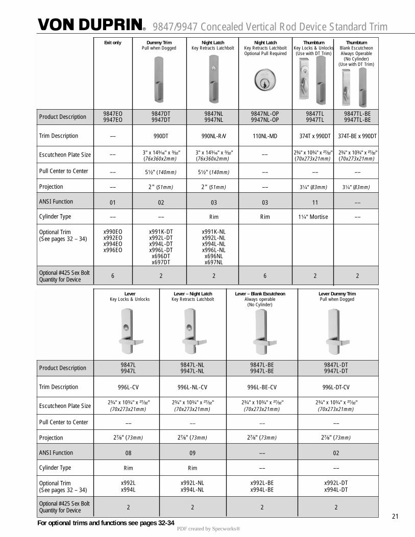
9847/9947 Concealed Vertical Rod Device Standard Trim
21
Exit only Dummy Trim Night Latch Night Latch Thumbturn ThumbturnPull when Dogged Key Retracts Latchbolt Key Retracts Latchbolt Key Locks & Unlocks Blank Escutcheon
Optional Pull Required (Use with DT Trim) Always Operable(No Cylinder)
(Use with DT Trim)
Product Description
Trim Description
Escutcheon Plate Size
Pull Center to Center
Projection
ANSI Function
Cylinder Type
Optional Trim(See pages 32 – 34)
Optional #425 Sex Bolt Quantity for Device
9847EO 9847DT 9847NL 9847NL-OP 9847TL 9847TL-BE9947EO 9947DT 9947NL 9947NL-OP 9947TL 9947TL-BE
–– 990DT 990NL-R/V 110NL-MD 374T x 990DT 374T-BE x 990DT
3" x 14³�₁₆" x ³�₃₂" 3" x 14³�₁₆" x ³�₃₂" 2³�₄" x 10³�₄" x ²⁷�₃₂" 2³�₄" x 10³�₄" x ²⁷�₃₂"(76x360x2mm) (76x360x2mm) (70x273x21mm) (70x273x21mm)
–– 5¹�₂" (140mm) 5¹�₂" (140mm) –– –– ––
–– 2" (51mm) 2" (51mm) –– 3¹�₄" (83mm) 3¹�₄" (83mm)
01 02 03 03 11 ––
–– –– Rim Rim 1¹�₄" Mortise ––
x990EO x991K-DT x991K-NLx992EO x992L-DT x992L-NLx994EO x994L-DT x994L-NLx996EO x996L-DT x996L-NL
x696DT x696NLx697DT x697NL
6 2 2 6 2 2
–– ––
Lever Lever – Night Latch Lever – Blank Escutcheon Lever Dummy TrimKey Locks & Unlocks Key Retracts Latchbolt Always operable Pull when Dogged
(No Cylinder)
Product Description
Trim Description
Escutcheon Plate Size
Pull Center to Center
Projection
ANSI Function
Cylinder Type
Optional Trim(See pages 32 – 34)
Optional #425 Sex Bolt Quantity for Device
9847L 9847L-NL 9847L-BE 9847L-DT9947L 9947L-NL 9947L-BE 9947L-DT
996L-CV 996L-NL-CV 996L-BE-CV 996L-DT-CV
2³�₄" x 10³�₄" x ²⁷�₃₂" 2³�₄" x 10³�₄" x ²⁷�₃₂" 2³�₄" x 10³�₄" x ²⁷�₃₂" 2³�₄" x 10³�₄" x ²⁷�₃₂"(70x273x21mm) (70x273x21mm) (70x273x21mm) (70x273x21mm)
–– –– –– ––
2⁷�₈" (73mm) 2⁷�₈" (73mm) 2⁷�₈" (73mm) 2⁷�₈" (73mm)
08 09 –– 02
Rim Rim –– ––
x992L x992L-NL x992L-BE x992L-DTx994L x994L-NL x994L-BE x994L-DT
2 2 2 2
For optional trims and functions see pages 32-34PDF created by Specworks®
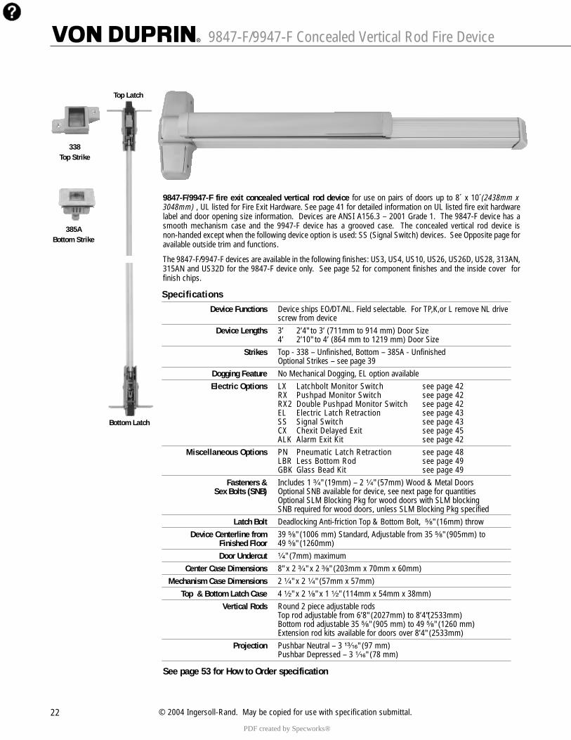
9847-F/9947-F Concealed Vertical Rod Fire Device
22 © 2004 Ingersoll-Rand. May be copied for use with specification submittal.
9847-F/9947-F fire exit concealed vertical rod device for use on pairs of doors up to 8´ x 10´(2438mm x3048mm) , UL listed for Fire Exit Hardware. See page 41 for detailed information on UL listed fire exit hardwarelabel and door opening size information. Devices are ANSI A156.3 – 2001 Grade 1. The 9847-F device has asmooth mechanism case and the 9947-F device has a grooved case. The concealed vertical rod device isnon-handed except when the following device option is used: SS (Signal Switch) devices. See Opposite page foravailable outside trim and functions.
The 9847-F/9947-F devices are available in the following finishes: US3, US4, US10, US26, US26D, US28, 313AN,315AN and US32D for the 9847-F device only. See page 52 for component finishes and the inside cover forfinish chips.
Top Latch
Bottom Latch
385A Bottom Strike
338 Top Strike
SpecificationsDevice Functions Device ships EO/DT/NL. Field selectable. For TP,K,or L remove NL drive
screw from deviceDevice Lengths 3’ 2’4" to 3’ (711mm to 914 mm) Door Size
4’ 2’10" to 4’ (864 mm to 1219 mm) Door SizeStrikes Top - 338 – Unfinished, Bottom – 385A - Unfinished
Optional Strikes – see page 39Dogging Feature No Mechanical Dogging, EL option availableElectric Options LX Latchbolt Monitor Switch see page 42
RX Pushpad Monitor Switch see page 42 RX2 Double Pushpad Monitor Switch see page 42EL Electric Latch Retraction see page 43 SS Signal Switch see page 43 CX Chexit Delayed Exit see page 45ALK Alarm Exit Kit see page 42
Miscellaneous Options PN Pneumatic Latch Retraction see page 48 LBR Less Bottom Rod see page 49 GBK Glass Bead Kit see page 49
Fasteners & Includes 1 ³�₄" (19mm) – 2 ¹�₄" (57mm) Wood & Metal DoorsSex Bolts (SNB) Optional SNB available for device, see next page for quantities
Optional SLM Blocking Pkg for wood doors with SLM blockingSNB required for wood doors, unless SLM Blocking Pkg specified
Latch Bolt Deadlocking Anti-friction Top & Bottom Bolt, ⁵�₈" (16mm) throw Device Centerline from 39 ⁵�₈" (1006 mm) Standard, Adjustable from 35 ⁵�₈" (905mm) to
Finished Floor 49 ⁵�₈" (1260mm)Door Undercut ¹�₄" (7mm) maximum
Center Case Dimensions 8" x 2 ³�₄" x 2 ³�₈" (203mm x 70mm x 60mm)Mechanism Case Dimensions 2 ¹�₄" x 2 ¹�₄" (57mm x 57mm)
Top & Bottom Latch Case 4 ¹�₂" x 2 ¹�₈" x 1 ¹�₂" (114mm x 54mm x 38mm)Vertical Rods Round 2 piece adjustable rods
Top rod adjustable from 6’8" (2027mm) to 8’4"(2533mm)Bottom rod adjustable 35 ⁵�₈" (905 mm) to 49 ⁵�₈" (1260 mm)Extension rod kits available for doors over 8’4" (2533mm)
Projection Pushbar Neutral – 3 ¹³�₁₆" (97 mm)Pushbar Depressed – 3 ¹�₁₆" (78 mm)
See page 53 for How to Order specification
PDF created by Specworks®
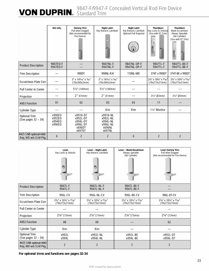
9847-F/9947-F Concealed Vertical Rod Fire Device Standard Trim
23
Exit only Dummy Trim Night Latch Night Latch Thumbturn ThumbturnPull when Dogged Key Retracts Latchbolt Key Retracts Latchbolt Key Locks & Unlocks Blank Escutcheon
(Not recommended for Optional Pull Required (Use with DT Trim) Always OperableFire Device) (No Cylinder)
(Use with DT Trim)
Product Description
Trim Description
Escutcheon Plate Size
Pull Center to Center
Projection
ANSI Function
Cylinder Type
Optional Trim(See pages 32 – 34)
#425 SNB optional-HMDReq. WD w/o SLM Pkg.
9847EO-F –– 9847NL-F 9847NL-OP-F 9847TL-F 9847TL-BE-F9947EO-F –– 9947NL-F 9947NL-OP-F 9947TL-F 9947TL-BE-F
–– 990DT 990NL-R/V 110NL-MD 374T x 990DT 374T-BE x 990DT
3" x 14³�₁₆" x ³�₃₂" 3" x 14³�₁₆" x ³�₃₂" 2³�₄" x 10³�₄" x ²⁷�₃₂" 2³�₄" x 10³�₄" x ²⁷�₃₂"(76x360x2mm) (76x360x2mm) (70x273x21mm) (70x273x21mm)
–– 5¹�₂" (140mm) 5¹�₂" (140mm) –– –– ––
–– 2" (51mm) 2" (51mm) –– 3¹�₄" (83mm) 3¹�₄" (83mm)
01 02 03 03 11 ––
–– –– Rim Rim 1¹�₄" Mortise ––
x990EO x991K-DT x991K-NLx992EO x992L-DT x992L-NLx994EO x994L-DT x994L-NLx996EO x996L-DT x996L-NL
x696DT x696NLx697DT x697NL
6 2 2 6 2 2
–– ––
Lever Lever – Night Latch Lever – Blank Escutcheon Lever Dummy TrimKey Locks & Unlocks Key Retracts Latchbolt Always operable Pull when Dogged
(No Cylinder) (Not recommended for Fire Device)
Product Description
Trim Description
Escutcheon Plate Size
Pull Center to Center
Projection
ANSI Function
Cylinder Type
Optional Trim(See pages 32 – 34)
#425 SNB optional-HMDReq. WD w/o SLM Pkg.
9847L-F 9847L-NL-F 9847L-BE-F ––9947L-F 9947L-NL-F 9947L-BE-F ––
996L-CV 996L-NL-CV 996L-BE-CV 996L-DT-CV
2³�₄" x 10³�₄" x ²⁷�₃₂" 2³�₄" x 10³�₄" x ²⁷�₃₂" 2³�₄" x 10³�₄" x ²⁷�₃₂" 2³�₄" x 10³�₄" x ²⁷�₃₂"(70x273x21mm) (70x273x21mm) (70x273x21mm) (70x273x21mm)
–– –– –– ––
2⁷�₈" (73mm) 2⁷�₈" (73mm) 2⁷�₈" (73mm) 2⁷�₈" (73mm)
08 09 –– 02
Rim Rim –– ––
x992L x992L-NL x992L-BE x992L-DTx994L x994L-NL x994L-BE x994L-DT
2 2 2 2
For optional trims and functions see pages 32-34
PDF created by Specworks®
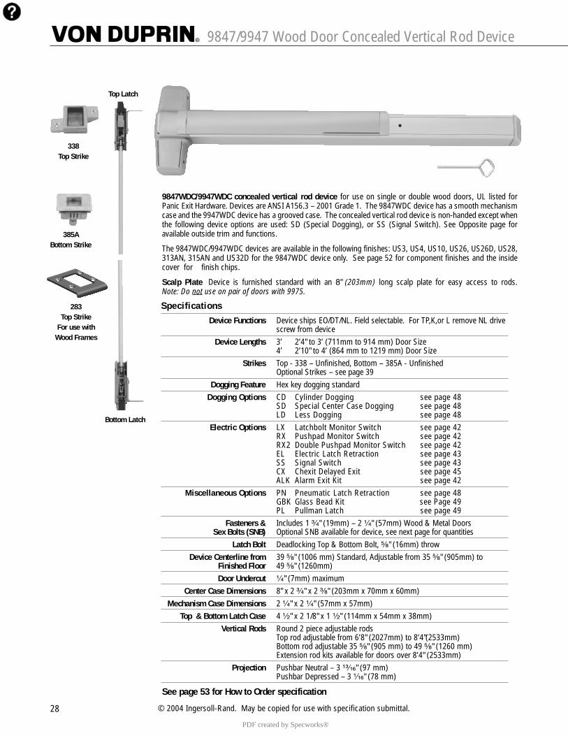
9847/9947 Wood Door Concealed Vertical Rod Device
28 © 2004 Ingersoll-Rand. May be copied for use with specification submittal.
9847WDC/9947WDC concealed vertical rod device for use on single or double wood doors, UL listed forPanic Exit Hardware. Devices are ANSI A156.3 – 2001 Grade 1. The 9847WDC device has a smooth mechanismcase and the 9947WDC device has a grooved case. The concealed vertical rod device is non-handed except whenthe following device options are used: SD (Special Dogging), or SS (Signal Switch). See Opposite page foravailable outside trim and functions.
The 9847WDC/9947WDC devices are available in the following finishes: US3, US4, US10, US26, US26D, US28,313AN, 315AN and US32D for the 9847WDC device only. See page 52 for component finishes and the insidecover for finish chips.
Scalp Plate Device is furnished standard with an 8" (203mm) long scalp plate for easy access to rods.Note: Do not use on pair of doors with 9975.
Top Latch
Bottom Latch
385A Bottom Strike
338 Top Strike
283Top Strike
For use with Wood Frames
SpecificationsDevice Functions Device ships EO/DT/NL. Field selectable. For TP,K,or L remove NL drive
screw from deviceDevice Lengths 3’ 2’4" to 3’ (711mm to 914 mm) Door Size
4’ 2’10" to 4’ (864 mm to 1219 mm) Door SizeStrikes Top - 338 – Unfinished, Bottom – 385A - Unfinished
Optional Strikes – see page 39Dogging Feature Hex key dogging standard
Dogging Options CD Cylinder Dogging see page 48 SD Special Center Case Dogging see page 48 LD Less Dogging see page 48
Electric Options LX Latchbolt Monitor Switch see page 42 RX Pushpad Monitor Switch see page 42 RX2 Double Pushpad Monitor Switch see page 42EL Electric Latch Retraction see page 43 SS Signal Switch see page 43 CX Chexit Delayed Exit see page 45ALK Alarm Exit Kit see page 42
Miscellaneous Options PN Pneumatic Latch Retraction see page 48 GBK Glass Bead Kit see Page 49PL Pullman Latch see page 49
Fasteners & Includes 1 ³�₄" (19mm) – 2 ¹�₄" (57mm) Wood & Metal DoorsSex Bolts (SNB) Optional SNB available for device, see next page for quantities
Latch Bolt Deadlocking Top & Bottom Bolt, ⁵�₈" (16mm) throwDevice Centerline from 39 ⁵�₈" (1006 mm) Standard, Adjustable from 35 ⁵�₈" (905mm) to
Finished Floor 49 ⁵�₈" (1260mm)Door Undercut ¹�₄" (7mm) maximum
Center Case Dimensions 8" x 2 ³�₄" x 2 ³�₈" (203mm x 70mm x 60mm)Mechanism Case Dimensions 2 ¹�₄" x 2 ¹�₄" (57mm x 57mm)
Top & Bottom Latch Case 4 ¹�₂" x 2 1/8" x 1 ¹�₂" (114mm x 54mm x 38mm)Vertical Rods Round 2 piece adjustable rods
Top rod adjustable from 6’8" (2027mm) to 8’4"(2533mm)Bottom rod adjustable 35 ⁵�₈" (905 mm) to 49 ⁵�₈" (1260 mm)Extension rod kits available for doors over 8’4" (2533mm)
Projection Pushbar Neutral – 3 ¹³�₁₆" (97 mm)Pushbar Depressed – 3 ¹�₁₆" (78 mm)
See page 53 for How to Order specification
PDF created by Specworks®

9847/9947 Wood Door Concealed Vertical Rod Device Standard Trim
29
Exit only Dummy Trim Night Latch Night Latch Thumbturn ThumbturnPull when Dogged Key Retracts Latchbolt Key Retracts Latchbolt Key Locks & Unlocks Blank Escutcheon
Optional Pull Required (Use with DT Trim) Always Operable(No Cylinder)
(Use with DT Trim)
Product Description
Trim Description
Escutcheon Plate Size
Pull Center to Center
Projection
ANSI Function
Cylinder Type
Optional Trim(See pages 32 – 34)
Optional #425 Sex Bolt Quantity for Device
9847WDC-EO 9847WDC-DT 9847WDC-NL 9847WDC-NL-OP 9847WDC-TL 9847WDC-TL-BE9947WDC-EO 9947WDC-DT 9947WDC-NL 9947WDC-NL-OP 9947WDC-TL 9947WDC-TL-BE
–– 990DT 990NL-R/V 110NL-WD 374T x 990DT 374T-BE x 990DT
3" x 14³�₁₆" x ³�₃₂" 3" x 14³�₁₆" x ³�₃₂" 2³�₄" x 10³�₄" x ²⁷�₃₂" 2³�₄" x 10³�₄" x ²⁷�₃₂"(76x360x2mm) (76x360x2mm) (70x273x21mm) (70x273x21mm)
–– 5¹�₂" (140mm) 5¹�₂" (140mm) –– –– ––
–– 2" (51mm) 2" (51mm) –– 3¹�₄" (83mm) 3¹�₄" (83mm)
01 02 03 03 11 ––
–– –– Rim Rim 1¹�₄" Mortise ––
x990EO x991K-DT x991K-NLx992EO x992L-DT x992L-NLx994EO x994L-DT x994L-NLx996EO x996L-DT x996L-NL
x696DT x696NLx697DT x697NL
6 2 2 6 2 2
–– ––
Lever Lever – Night Latch Lever – Blank Escutcheon Lever Dummy TrimKey Locks & Unlocks Key Retracts Latchbolt Always operable Pull when Dogged
(No Cylinder)
Product Description
Trim Description
Escutcheon Plate Size
Pull Center to Center
Projection
ANSI Function
Cylinder Type
Optional Trim(See pages 32 – 34)
Optional #425 Sex Bolt Quantity for Device
9847WDC-L 9847WDC-L-NL 9847WDC-L-BE 9847WDC-L-DT9947WDC-L 9947WDC-L-NL 9947WDC-L-BE 9947WDC-L-DT
996L-CV 996L-NL-CV 996L-BE-CV 996L-DT-CV
2³�₄" x 10³�₄" x ²⁷�₃₂" 2³�₄" x 10³�₄" x ²⁷�₃₂" 2³�₄" x 10³�₄" x ²⁷�₃₂" 2³�₄" x 10³�₄" x ²⁷�₃₂"(70x273x21mm) (70x273x21mm) (70x273x21mm) (70x273x21mm)
–– –– –– ––
2⁷�₈" (73mm) 2⁷�₈" (73mm) 2⁷�₈" (73mm) 2⁷�₈" (73mm)
08 09 –– 02
Rim Rim –– ––
x992L x992L-NL x992L-BE x992L-DTx994L x994L-NL x994L-BE x994L-DT
2 2 2 2
For optional trims and functions see pages 32-34PDF created by Specworks®

4 © 2004 Ingersoll-Rand. May be copied for use with specification submittal.
98/99™ Rim Exit Device
299 Strike
98 and 99 rim exit devices for all types of single and double doors with mullion, UL listed for Panic ExitHardware. Devices are ANSI A156.3 – 2001 Grade 1. The 98 device has a smooth mechanism case and the99 device has a grooved case. The rim device is non-handed except when the following device options areused: SD (Special Dogging), -2 (Double Cylinder) or SS (Signal Switch). See Opposite page for availableoutside trim and device functions. Covers stock hollow metal doors with 86 or 161 cutouts on single doors(may cover cutouts on pairs – consult template).
The 98/99 devices are available in the following finishes: US3, US4, US10, US26, US26D, US28, 313AN,315AN and US32D for the 98 device only. See page 52 for component finishes and the inside cover forfinish chips.
Specifications
Device Functions Device ships EO/DT/NL. Field selectable. For TP,K,or L remove NL drive screw from device
Device Lengths 3’ 2’4" to 3’ (711mm to 914 mm) Door Size4’ 2’10" to 4’ (864 mm to 1219 mm) Door Size
Strikes 299 – Dull BlackOptional Strikes – see page 39
Dogging Feature Hex key dogging standard
Dogging Options CD Cylinder Dogging see page 48 SD Special Center Case Dogging see page 48 LD Less Dogging see page 48
Electric Options LX Latchbolt Monitor Switch see page 42 RX Pushpad Monitor Switch see page 42 RX2 Double Pushpad Monitor Switch see page 42E Electric Locking & Unlocking see page 44EL Electric Latch Retraction see page 43 SS Signal Switch see page 43 CX Chexit Delayed Exit see page 45ALK Alarm Exit Kit see page 42
Miscellaneous Options PN Pneumatic Latch Retraction see page 48 -2 Double Cylinder see page 48 GBK Glass Bead Kit see page 49
Fasteners & Includes 1 ³�₄" (19mm) – 2 ¹�₄" (57mm) Wood & Metal DoorsSex Bolts (SNB) Optional SNB available for device, see next page for quantities
Latch Bolt Deadlocking, ³�₄" (19mm) throw
Device Centerline from 39 ¹³�₁₆" (1011 mm)Finished Floor 39 ¹¹�₁₆" (1008 mm) with Mullion
Center Case Dimensions 8" x 2 ³�₄" x 2 ³�₈" (203mm x 70mm x 60mm)
Mechanism Case Dimensions 2 ¹�₄" x 2 ¹�₄" (57mm x 57mm)
Projection Pushbar Neutral – 3 ¹³�₁₆" (97 mm)Pushbar Depressed – 3 ¹�₁₆" (78 mm)
See page 53 for How to Order specification
PDF created by Specworks®
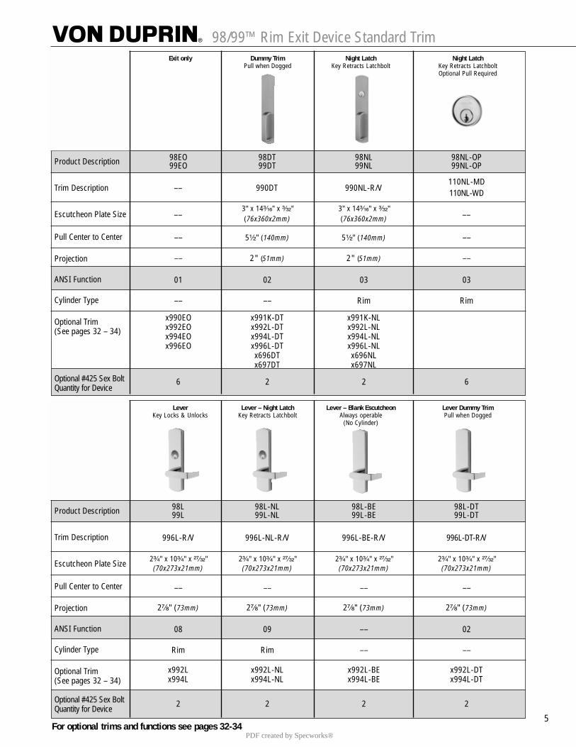
98/99™ Rim Exit Device Standard Trim
5
Exit only Dummy Trim Night Latch Night LatchPull when Dogged Key Retracts Latchbolt Key Retracts Latchbolt
Optional Pull Required
Product Description
Trim Description
Escutcheon Plate Size
Pull Center to Center
Projection
ANSI Function
Cylinder Type
Optional Trim(See pages 32 – 34)
Optional #425 Sex Bolt Quantity for Device
98EO 98DT 98NL 98NL-OP99EO 99DT 99NL 99NL-OP
110NL-MD110NL-WD
3" x 14³�₁₆" x ³�₃₂" 3" x 14³�₁₆" x ³�₃₂"(76x360x2mm) (76x360x2mm)
–– 5¹�₂" (140mm) 5¹�₂" (140mm) ––
–– 2" (51mm) 2" (51mm) ––
01 02 03 03
–– –– Rim Rim
x990EO x991K-DT x991K-NLx992EO x992L-DT x992L-NLx994EO x994L-DT x994L-NLx996EO x996L-DT x996L-NL
x696DT x696NLx697DT x697NL
6 2 2 6
–– 990DT 990NL-R/V
–– ––
Lever Lever – Night Latch Lever – Blank Escutcheon Lever Dummy TrimKey Locks & Unlocks Key Retracts Latchbolt Always operable Pull when Dogged
(No Cylinder)
Product Description
Trim Description
Escutcheon Plate Size
Pull Center to Center
Projection
ANSI Function
Cylinder Type
Optional Trim(See pages 32 – 34)
Optional #425 Sex Bolt Quantity for Device
98L 98L-NL 98L-BE 98L-DT99L 99L-NL 99L-BE 99L-DT
996L-R/V 996L-NL-R/V 996L-BE-R/V 996L-DT-R/V
2³�₄" x 10³�₄" x ²⁷�₃₂" 2³�₄" x 10³�₄" x ²⁷�₃₂" 2³�₄" x 10³�₄" x ²⁷�₃₂" 2³�₄" x 10³�₄" x ²⁷�₃₂"(70x273x21mm) (70x273x21mm) (70x273x21mm) (70x273x21mm)
–– –– –– ––
2⁷�₈" (73mm) 2⁷�₈" (73mm) 2⁷�₈" (73mm) 2⁷�₈" (73mm)
08 09 –– 02
Rim Rim –– ––
x992L x992L-NL x992L-BE x992L-DTx994L x994L-NL x994L-BE x994L-DT
2 2 2 2
For optional trims and functions see pages 32-34PDF created by Specworks®
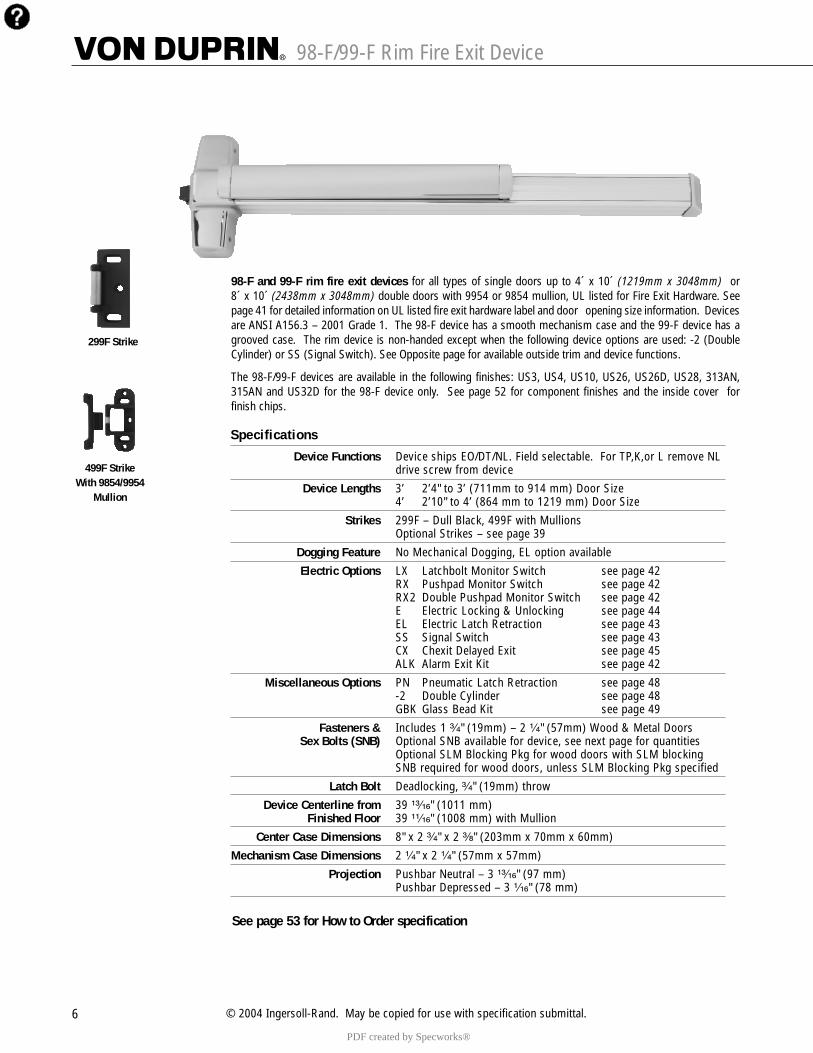
98-F/99-F Rim Fire Exit Device
6 © 2004 Ingersoll-Rand. May be copied for use with specification submittal.
98-F and 99-F rim fire exit devices for all types of single doors up to 4´ x 10´ (1219mm x 3048mm) or8´ x 10´ (2438mm x 3048mm) double doors with 9954 or 9854 mullion, UL listed for Fire Exit Hardware. Seepage 41 for detailed information on UL listed fire exit hardware label and door opening size information. Devicesare ANSI A156.3 – 2001 Grade 1. The 98-F device has a smooth mechanism case and the 99-F device has agrooved case. The rim device is non-handed except when the following device options are used: -2 (DoubleCylinder) or SS (Signal Switch). See Opposite page for available outside trim and device functions.
The 98-F/99-F devices are available in the following finishes: US3, US4, US10, US26, US26D, US28, 313AN,315AN and US32D for the 98-F device only. See page 52 for component finishes and the inside cover forfinish chips.
299F Strike
499F StrikeWith 9854/9954
Mullion
Specifications
Device Functions Device ships EO/DT/NL. Field selectable. For TP,K,or L remove NL drive screw from device
Device Lengths 3’ 2’4" to 3’ (711mm to 914 mm) Door Size4’ 2’10" to 4’ (864 mm to 1219 mm) Door Size
Strikes 299F – Dull Black, 499F with MullionsOptional Strikes – see page 39
Dogging Feature No Mechanical Dogging, EL option available
Electric Options LX Latchbolt Monitor Switch see page 42 RX Pushpad Monitor Switch see page 42 RX2 Double Pushpad Monitor Switch see page 42E Electric Locking & Unlocking see page 44EL Electric Latch Retraction see page 43 SS Signal Switch see page 43 CX Chexit Delayed Exit see page 45ALK Alarm Exit Kit see page 42
Miscellaneous Options PN Pneumatic Latch Retraction see page 48 -2 Double Cylinder see page 48 GBK Glass Bead Kit see page 49
Fasteners & Includes 1 ³�₄" (19mm) – 2 ¹�₄" (57mm) Wood & Metal DoorsSex Bolts (SNB) Optional SNB available for device, see next page for quantities
Optional SLM Blocking Pkg for wood doors with SLM blockingSNB required for wood doors, unless SLM Blocking Pkg specified
Latch Bolt Deadlocking, ³�₄" (19mm) throw
Device Centerline from 39 ¹³�₁₆" (1011 mm)Finished Floor 39 ¹¹�₁₆" (1008 mm) with Mullion
Center Case Dimensions 8" x 2 ³�₄" x 2 ³�₈" (203mm x 70mm x 60mm)
Mechanism Case Dimensions 2 ¹�₄" x 2 ¹�₄" (57mm x 57mm)
Projection Pushbar Neutral – 3 ¹³�₁₆" (97 mm)Pushbar Depressed – 3 ¹�₁₆" (78 mm)
See page 53 for How to Order specification
PDF created by Specworks®
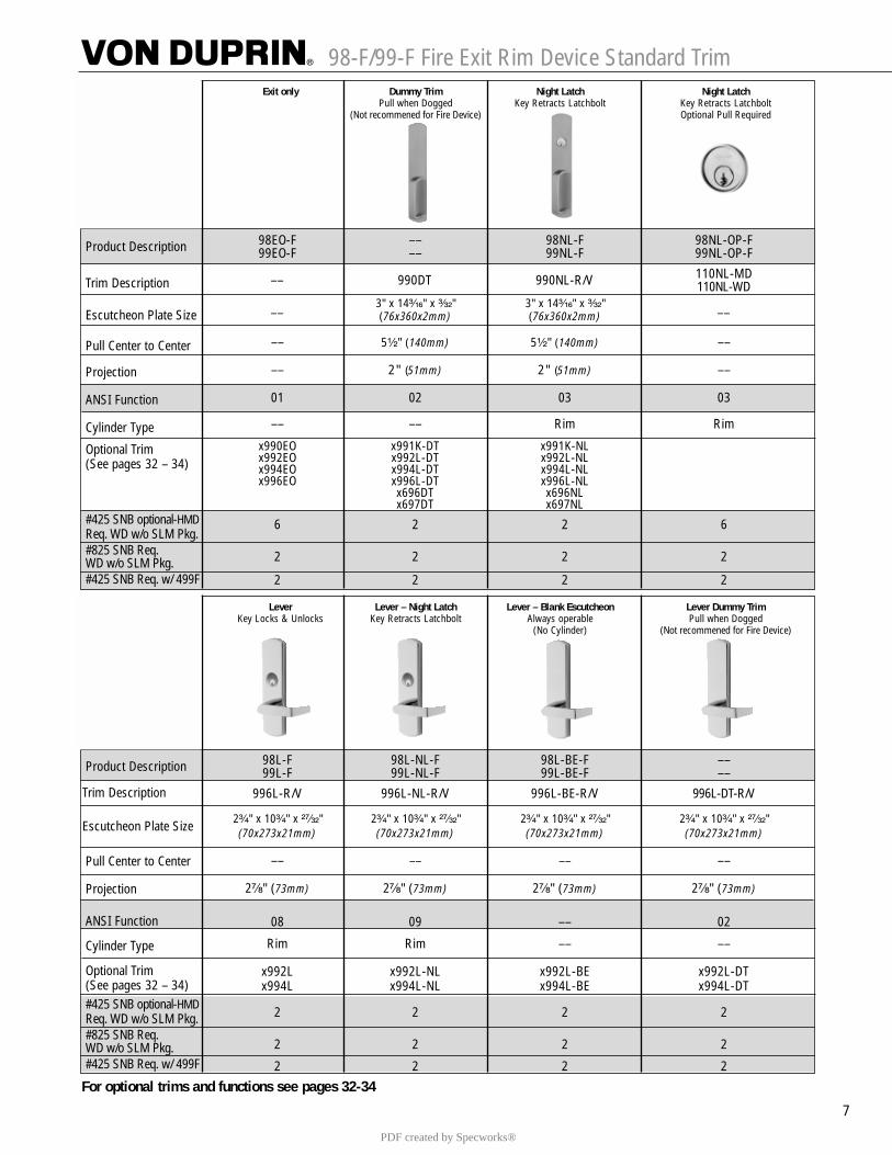
98-F/99-F Fire Exit Rim Device Standard Trim
7
Exit only Dummy Trim Night Latch Night LatchPull when Dogged Key Retracts Latchbolt Key Retracts Latchbolt
(Not recommened for Fire Device) Optional Pull Required
Product Description
Trim Description
Escutcheon Plate Size
Pull Center to Center
Projection
ANSI Function
Cylinder Type
Optional Trim(See pages 32 – 34)
#425 SNB optional-HMDReq. WD w/o SLM Pkg. #825 SNB Req. WD w/o SLM Pkg.#425 SNB Req. w/ 499F
98EO-F –– 98NL-F 98NL-OP-F99EO-F –– 99NL-F 99NL-OP-F
110NL-MD110NL-WD
3" x 14³�₁₆" x ³�₃₂" 3" x 14³�₁₆" x ³�₃₂"(76x360x2mm) (76x360x2mm)
–– 5¹�₂" (140mm) 5¹�₂" (140mm) ––
–– 2" (51mm) 2" (51mm) ––
01 02 03 03
–– –– Rim Rim
x990EO x991K-DT x991K-NLx992EO x992L-DT x992L-NLx994EO x994L-DT x994L-NLx996EO x996L-DT x996L-NL
x696DT x696NLx697DT x697NL
6 2 2 6
2 2 2 2
2 2 2 2
–– 990DT 990NL-R/V
–– ––
Lever Lever – Night Latch Lever – Blank Escutcheon Lever Dummy TrimKey Locks & Unlocks Key Retracts Latchbolt Always operable Pull when Dogged
(No Cylinder) (Not recommened for Fire Device)
Product Description
Trim Description
Escutcheon Plate Size
Pull Center to Center
Projection
ANSI Function
Cylinder Type
Optional Trim(See pages 32 – 34)#425 SNB optional-HMDReq. WD w/o SLM Pkg. #825 SNB Req. WD w/o SLM Pkg.#425 SNB Req. w/ 499F
98L-F 98L-NL-F 98L-BE-F ––99L-F 99L-NL-F 99L-BE-F ––
996L-R/V 996L-NL-R/V 996L-BE-R/V 996L-DT-R/V
2³�₄" x 10³�₄" x ²⁷�₃₂" 2³�₄" x 10³�₄" x ²⁷�₃₂" 2³�₄" x 10³�₄" x ²⁷�₃₂" 2³�₄" x 10³�₄" x ²⁷�₃₂"(70x273x21mm) (70x273x21mm) (70x273x21mm) (70x273x21mm)
–– –– –– ––
2⁷�₈" (73mm) 2⁷�₈" (73mm) 2⁷�₈" (73mm) 2⁷�₈" (73mm)
08 09 –– 02
Rim Rim –– ––
x992L x992L-NL x992L-BE x992L-DTx994L x994L-NL x994L-BE x994L-DT
2 2 2 2
2 2 2 2
2 2 2 2
For optional trims and functions see pages 32-34
PDF created by Specworks®
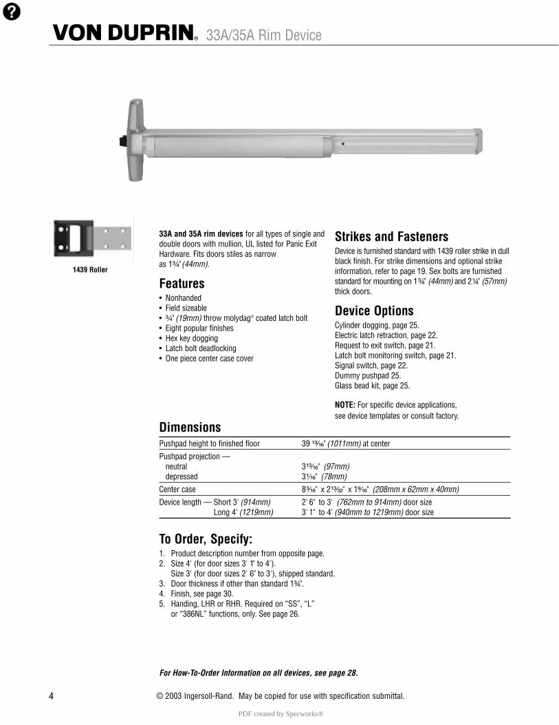
4 © 2003 Ingersoll-Rand. May be copied for use with specification submittal.44
33A and 35A rim devices for all types of single and double doors with mullion, UL listed for Panic Exit Hardware. Fits doors stiles as narrow as 1³�₄" (44mm).
Features• Nonhanded• Field sizeable• ³�₄" (19mm) throw molydag® coated latch bolt• Eight popular finishes• Hex key dogging• Latch bolt deadlocking• One piece center case cover
DimensionsPushpad height to finished floor 39 ¹³�₁₆" (1011mm) at center
Pushpad projection —neutral 3¹³�₁₆" (97mm)depressed 3¹�₁₆" (78mm)
Center case 8³�₁₆" x 2¹³�₃₂" x 1⁹�₁₆" (208mm x 62mm x 40mm)
Device length — Short 3' (914mm) 2' 6" to 3' (762mm to 914mm) door sizeLong 4' (1219mm) 3' 1" to 4' (940mm to 1219mm) door size
To Order, Specify:1. Product description number from opposite page.2. Size 4' (for door sizes 3' 1" to 4').
Size 3' (for door sizes 2' 6" to 3'), shipped standard.3. Door thickness if other than standard 1³�₄".4. Finish, see page 30.5. Handing, LHR or RHR. Required on “SS”, “L”
or “386NL” functions, only. See page 26.
For How-To-Order Information on all devices, see page 28.
1439 Roller
Strikes and Fasteners Device is furnished standard with 1439 roller strike in dullblack finish. For strike dimensions and optional strikeinformation, refer to page 19. Sex bolts are furnishedstandard for mounting on 1³�₄" (44mm) and 2¹�₄" (57mm)thick doors.
Device Options Cylinder dogging, page 25.Electric latch retraction, page 22.Request to exit switch, page 21.Latch bolt monitoring switch, page 21.Signal switch, page 22.Dummy pushpad 25.Glass bead kit, page 25.
NOTE: For specific device applications,see device templates or consult factory.
33A/35A Rim Device
PDF created by Specworks®
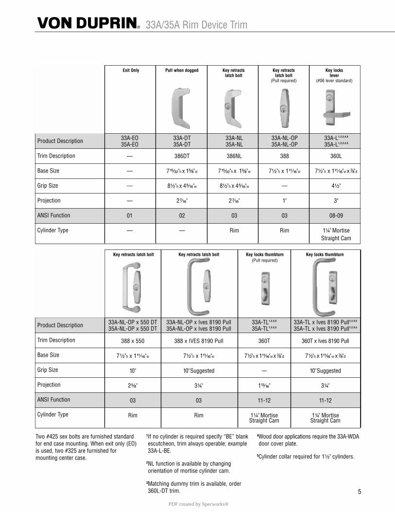
Key retracts latch bolt Key retracts latch bolt Key locks thumbturn Key locks thumbturn(Pull required)
Product Description
Trim Description
Base Size
Grip Size
Projection
ANSI Function
Cylinder Type
Exit Only Pull when dogged Key retracts Key retracts Key lockslatch bolt latch bolt lever
(Pull required) (#06 lever standard)
Product Description
Trim Description
Base Size
Grip Size
Projection
ANSI Function
Cylinder Type
5
33A-EO 33A-DT 33A-NL 33A-NL-OP 33A-L1,2,3,4,5
35A-EO 35A-DT 35A-NL 35A-NL-OP 35A-L1,2,3,4,5
–– 386DT 386NL 388 360L
–– 7¹⁵�₃₂"h x 1⁵�₈"w 7¹⁵�₃₂"h x 1⁵�₈"w 7¹�₂"h x 1¹¹�₁₆"w 7¹�₂"h x 1¹¹�₁₆"w x ⁷�₈"d
–– 8¹�₂"h x 4⁵�₁₆"w 8¹�₂"h x 4⁵�₁₆"w –– 4¹�₂"
–– 2⁷�₁₆" 2⁷�₁₆" 1" 3"
01 02 03 03 08-09
–– –– Rim Rim 1¹�₄" MortiseStraight Cam
Two #425 sex bolts are furnished standardfor end case mounting. When exit only (EO)is used, two #325 are furnished formounting center case.
1If no cylinder is required specify “BE” blankescutcheon, trim always operable; example 33A-L-BE.
2NL function is available by changing orientation of mortise cylinder cam.
3Matching dummy trim is available, order 360L-DT trim.
4Wood door applications require the 33A-WDAdoor cover plate.
5Cylinder collar required for 1¹�₂" cylinders.
33A-NL-OP x 550 DT 33A-NL-OP x Ives 8190 Pull 33A-TL1,2,4,5 33A-TL x Ives 8190 Pull1,2,4,5
35A-NL-OP x 550 DT 35A-NL-OP x Ives 8190 Pull 35A-TL1,2,4,5 35A-TL x Ives 8190 Pull1,2,4,5
388 x 550 388 x IVES 8190 Pull 360T 360T x Ives 8190 Pull
7¹�₂"h x 1¹¹�₁₆"w 7¹�₂"h x 1¹¹�₁₆"w 7¹�₂"h x 1¹¹�₁₆"w x ⁷�₈"d 7¹�₂"h x 1¹¹�₁₆"w x ⁷�₈"d
10" 10" Suggested –– 10" Suggested
2⁵�₈" 3¹�₄" 1¹³�₁₆" 3¹�₄"
03 03 11-12 11-12
Rim Rim 1¹�₄" Mortise 1¹�₄" MortiseStraight Cam Straight Cam
33A/35A Rim Device Trim
PDF created by Specworks®
21
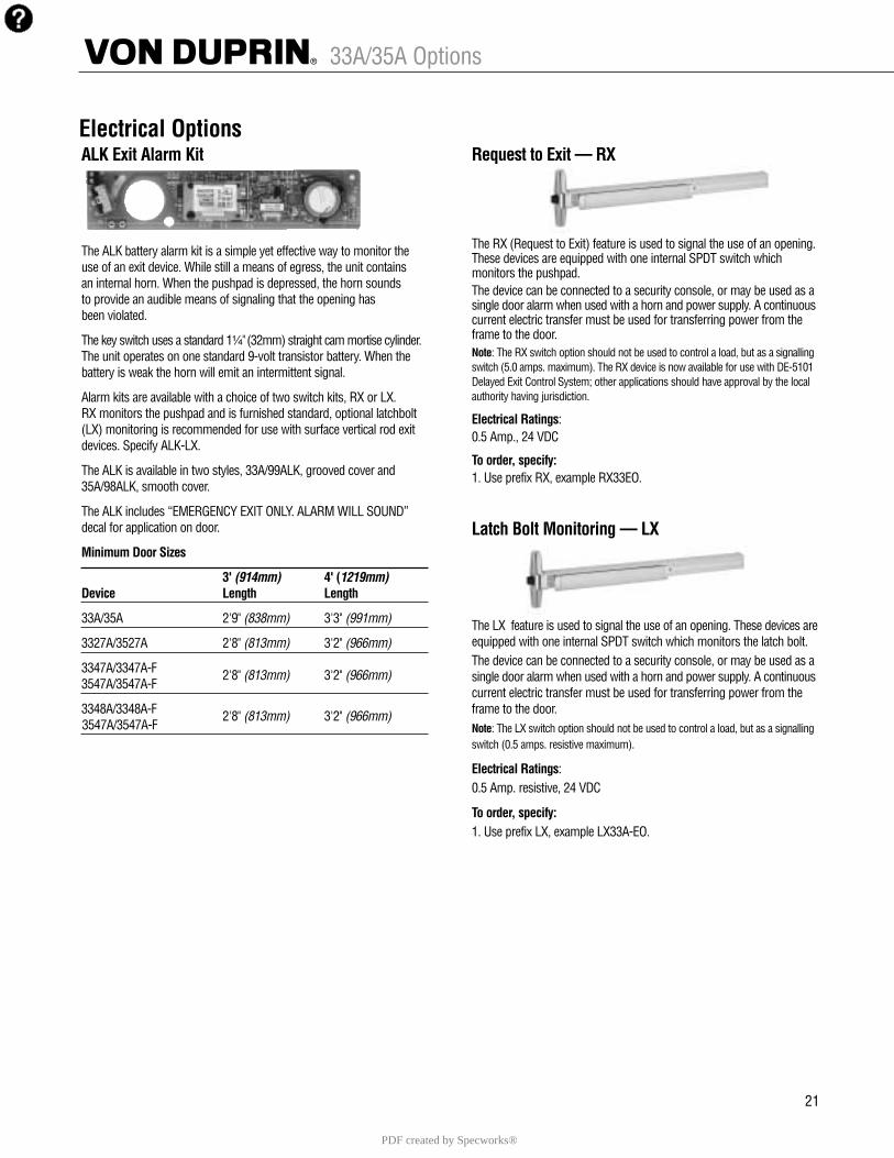
ALK Exit Alarm Kit
The ALK battery alarm kit is a simple yet effective way to monitor theuse of an exit device. While still a means of egress, the unit contains an internal horn. When the pushpad is depressed, the horn sounds to provide an audible means of signaling that the opening has been violated.
The key switch uses a standard 1¹�₄" (32mm) straight cam mortise cylinder.The unit operates on one standard 9-volt transistor battery. When thebattery is weak the horn will emit an intermittent signal.
Alarm kits are available with a choice of two switch kits, RX or LX.RX monitors the pushpad and is furnished standard, optional latchbolt(LX) monitoring is recommended for use with surface vertical rod exitdevices. Specify ALK-LX.
The ALK is available in two styles, 33A/99ALK, grooved cover and35A/98ALK, smooth cover.
The ALK includes “EMERGENCY EXIT ONLY. ALARM WILL SOUND”decal for application on door.
Minimum Door Sizes
3' (914mm) 4' (1219mm)Device Length Length
33A/35A 2'9" (838mm) 3'3" (991mm)
3327A/3527A 2'8" (813mm) 3'2" (966mm)
3347A/3347A-F 2'8" (813mm) 3'2" (966mm)3547A/3547A-F
3348A/3348A-F 2'8" (813mm) 3'2" (966mm)3547A/3547A-F
Request to Exit — RX
The RX (Request to Exit) feature is used to signal the use of an opening.These devices are equipped with one internal SPDT switch which monitors the pushpad. The device can be connected to a security console, or may be used as asingle door alarm when used with a horn and power supply. A continuouscurrent electric transfer must be used for transferring power from theframe to the door.Note: The RX switch option should not be used to control a load, but as a signallingswitch (5.0 amps. maximum). The RX device is now available for use with DE-5101Delayed Exit Control System; other applications should have approval by the localauthority having jurisdiction.
Electrical Ratings: 0.5 Amp., 24 VDC
To order, specify:1. Use prefix RX, example RX33EO.
Latch Bolt Monitoring — LX
The LX feature is used to signal the use of an opening. These devices areequipped with one internal SPDT switch which monitors the latch bolt. The device can be connected to a security console, or may be used as asingle door alarm when used with a horn and power supply. A continuouscurrent electric transfer must be used for transferring power from theframe to the door.Note: The LX switch option should not be used to control a load, but as a signallingswitch (0.5 amps. resistive maximum).
Electrical Ratings: 0.5 Amp. resistive, 24 VDC
To order, specify:1. Use prefix LX, example LX33A-EO.
Electrical Options
33A/35A Options
PDF created by Specworks®
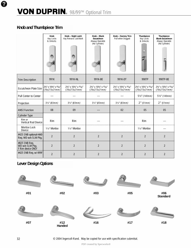
98/99™ Optional Trim
32 © 2004 Ingersoll-Rand. May be copied for use with specification submittal.
Knob Knob – Night Latch Knob – Blank Knob – Dummy Trim Thumbpiece ThumbpieceKey Locks Key Retracts Latchbolt Escutcheon Pull when Dogged Key Locks Blank Escutcheon& Unlocks Alwaya Operable & Unlocks Always Operable
(No Cylinder) (No Cylinder)
Trim Description
Escutcheon Plate Size
Pull Center to Center
Projection
ANSI Function
Cylinder TypeRim or Vertical Rod Device
Mortise Lock Device
#425 SNB optional-HMDReq. WD w/o SLM Pkg.
#825 SNB Req. WD w/o SLM Pkg.F Rim device ONLY#425 SNB Req. w/ 499F
991K 991K-NL 991K-BE 991K-DT 990TP 990TP-BE
2³�₄" x 10³�₄" x ²⁷�₃₂" 2³�₄" x 10³�₄" x ²⁷�₃₂" 2³�₄" x 10³�₄" x ²⁷�₃₂" 2³�₄" x 10³�₄" x ²⁷�₃₂" 2³�₄" x 10³�₄" x ²⁷�₃₂" 2³�₄" x 10³�₄" x ²⁷�₃₂"(70x273x21mm) (70x273x21mm) (70x273x21mm) (70x273x21mm) (70x273x21mm) (70x273x21mm)
–– –– –– –– 5¹�₂" (140mm) 5¹�₂" (140mm)
3¹�₄" (83mm) 3¹�₄" (83mm) 3¹�₄" (83mm) 3¹�₄" (83mm) 2" (51mm) 2" (51mm)
08 09 –– 02 05 05
Rim Rim –– –– Rim ––
1¹�₄" Mortise 1¹�₄" Mortise 1¹�₄" Mortise ––
2 2 2 2 2 2
2 2 2 2 2 2
2 2 2 2 2 2
Knob and Thumbpiece Trim
Lever Design Options
#01 #02 #03 #05 #06Standard
#07 #12 #16 #17 #18Handed
PDF created by Specworks®
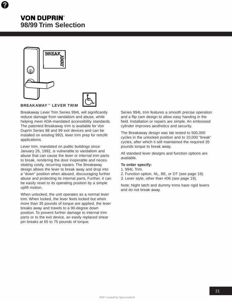
98/99 Trim Selection T
21
BREAKAWAYE LEVER TRIM
Breakaway Lever Trim Series 994L will significantlyreduce damage from vandalism and abuse, whilehelping meet ADA-mandated accessibility standards.The patented Breakaway trim is available for VonDuprin Series 98 and 99 exit devices and can beinstalled on existing 992L lever trim prep for retrofitapplications.
Lever trim, mandated on public buildings sinceJanuary 26, 1992, is vulnerable to vandalism andabuse that can cause the lever or internal trim partsto break, rendering the door inoperable and neces-sitating costly, recurring repairs. The Breakawaydesign allows the lever to break away and drop intoa “down” position when abused, discouraging furtherabuse and protecting its internal parts. Further, it canbe easily reset to its operating position by a simpleuplift motion.
When unlocked, the unit operates as a normal levertrim. When locked, the lever feels locked but whenmore than 35 pounds of torque are applied, the leverbreaks away and travels to a 90-degree downposition. To prevent further damage to internal trimparts or to the exit device, an easily replaced shearpin breaks at 65 to 75 pounds of torque.
Series 994L trim features a smooth precise operationand a flip cam design to allow easy handing in thefield. Installation or repairs are simple. An embossedcylinder improves aesthetics and security.
The Breakaway design was lab tested to 500,000cycles in the unlocked position and to 10,000 “break”cycles, after which it still maintained the required 35pounds torque to break away.
All standard lever designs and function options areavailable.
To or der specify:1. 994L Trim.2. Function option, NL, BE, or DT (see page 19).3. Lever style, other than #06 (see page 19).
Note: Night latch and dummy trims have rigid leversand do not break away.
PDF created by Specworks®
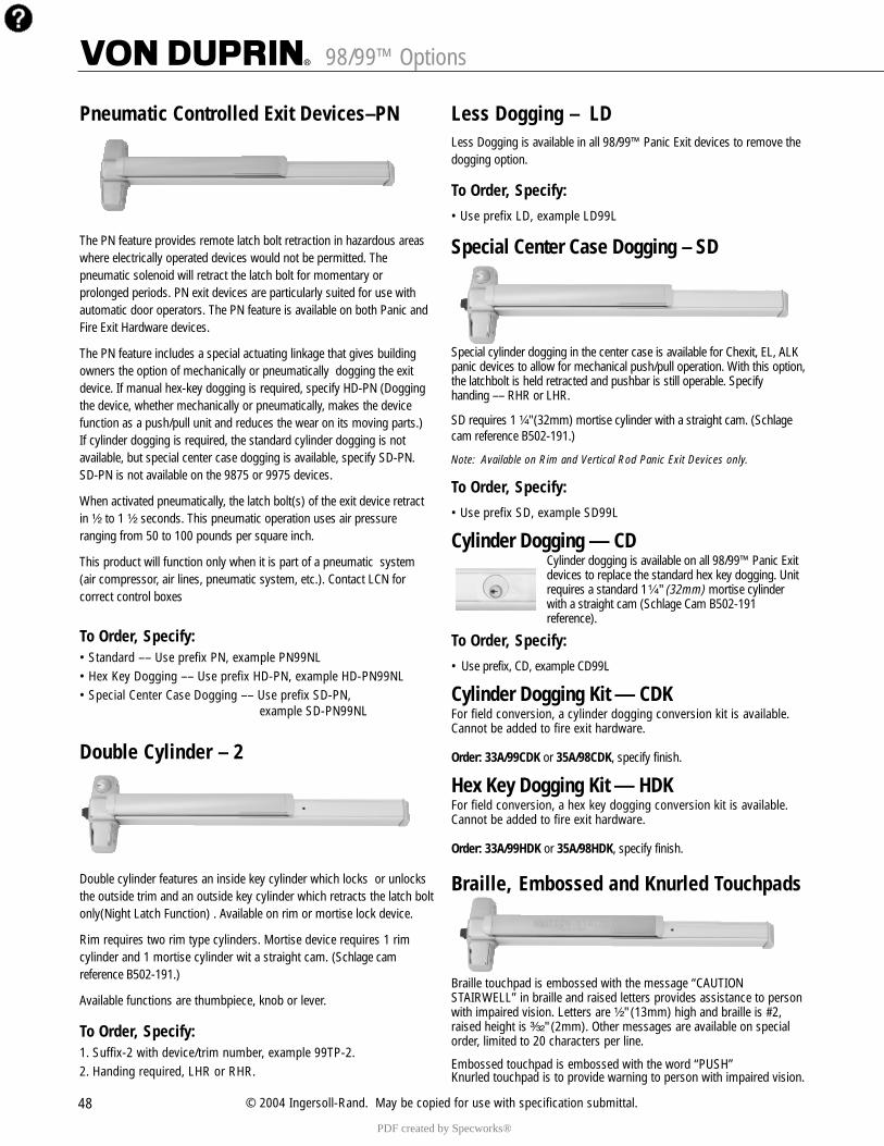
48 © 2004 Ingersoll-Rand. May be copied for use with specification submittal.
Pneumatic Controlled Exit Devices–PN
The PN feature provides remote latch bolt retraction in hazardous areaswhere electrically operated devices would not be permitted. Thepneumatic solenoid will retract the latch bolt for momentary orprolonged periods. PN exit devices are particularly suited for use withautomatic door operators. The PN feature is available on both Panic andFire Exit Hardware devices.
The PN feature includes a special actuating linkage that gives buildingowners the option of mechanically or pneumatically dogging the exitdevice. If manual hex-key dogging is required, specify HD-PN (Doggingthe device, whether mechanically or pneumatically, makes the devicefunction as a push/pull unit and reduces the wear on its moving parts.)If cylinder dogging is required, the standard cylinder dogging is notavailable, but special center case dogging is available, specify SD-PN.SD-PN is not available on the 9875 or 9975 devices.
When activated pneumatically, the latch bolt(s) of the exit device retractin ¹�₂ to 1 ¹�₂ seconds. This pneumatic operation uses air pressure ranging from 50 to 100 pounds per square inch.
This product will function only when it is part of a pneumatic system(air compressor, air lines, pneumatic system, etc.). Contact LCN for correct control boxes
To Order, Specify:• Standard –– Use prefix PN, example PN99NL• Hex Key Dogging –– Use prefix HD-PN, example HD-PN99NL• Special Center Case Dogging –– Use prefix SD-PN,
example SD-PN99NL
Double Cylinder – 2
Double cylinder features an inside key cylinder which locks or unlocksthe outside trim and an outside key cylinder which retracts the latch boltonly(Night Latch Function) . Available on rim or mortise lock device.
Rim requires two rim type cylinders. Mortise device requires 1 rimcylinder and 1 mortise cylinder wit a straight cam. (Schlage camreference B502-191.)
Available functions are thumbpiece, knob or lever.
To Order, Specify:1. Suffix-2 with device/trim number, example 99TP-2.2. Handing required, LHR or RHR.
Less Dogging – LDLess Dogging is available in all 98/99™ Panic Exit devices to remove thedogging option.
To Order, Specify:• Use prefix LD, example LD99L
Special Center Case Dogging – SD
Special cylinder dogging in the center case is available for Chexit, EL, ALKpanic devices to allow for mechanical push/pull operation. With this option,the latchbolt is held retracted and pushbar is still operable. Specifyhanding –– RHR or LHR.
SD requires 1 ¹�₄" (32mm) mortise cylinder with a straight cam. (Schlagecam reference B502-191.)
Note: Available on Rim and Vertical Rod Panic Exit Devices only.
To Order, Specify:• Use prefix SD, example SD99L
Cylinder Dogging — CDCylinder dogging is available on all 98/99™ Panic Exitdevices to replace the standard hex key dogging. Unitrequires a standard 1¹�₄" (32mm) mortise cylinderwith a straight cam (Schlage Cam B502-191reference).
To Order, Specify:• Use prefix, CD, example CD99L
Cylinder Dogging Kit — CDKFor field conversion, a cylinder dogging conversion kit is available.Cannot be added to fire exit hardware.
Order: 33A/99CDK or 35A/98CDK, specify finish.
Hex Key Dogging Kit — HDKFor field conversion, a hex key dogging conversion kit is available.Cannot be added to fire exit hardware.
Order: 33A/99HDK or 35A/98HDK, specify finish.
Braille, Embossed and Knurled Touchpads
Braille touchpad is embossed with the message “CAUTIONSTAIRWELL” in braille and raised letters provides assistance to personwith impaired vision. Letters are ¹�₂" (13mm) high and braille is #2,raised height is ³�₃₂" (2mm). Other messages are available on specialorder, limited to 20 characters per line.
Embossed touchpad is embossed with the word “PUSH”Knurled touchpad is to provide warning to person with impaired vision.
98/99™ Options
PDF created by Specworks®
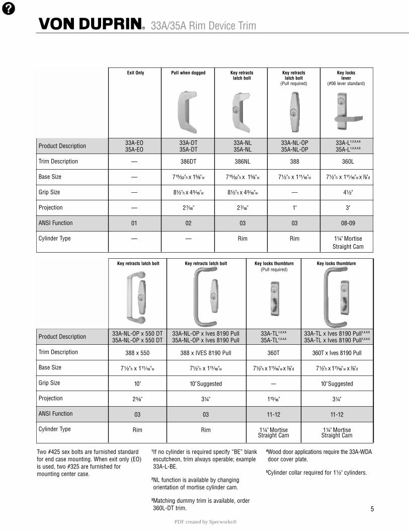
Key retracts latch bolt Key retracts latch bolt Key locks thumbturn Key locks thumbturn(Pull required)
Product Description
Trim Description
Base Size
Grip Size
Projection
ANSI Function
Cylinder Type
Exit Only Pull when dogged Key retracts Key retracts Key lockslatch bolt latch bolt lever
(Pull required) (#06 lever standard)
Product Description
Trim Description
Base Size
Grip Size
Projection
ANSI Function
Cylinder Type
5
33A-EO 33A-DT 33A-NL 33A-NL-OP 33A-L1,2,3,4,5
35A-EO 35A-DT 35A-NL 35A-NL-OP 35A-L1,2,3,4,5
–– 386DT 386NL 388 360L
–– 7¹⁵�₃₂"h x 1⁵�₈"w 7¹⁵�₃₂"h x 1⁵�₈"w 7¹�₂"h x 1¹¹�₁₆"w 7¹�₂"h x 1¹¹�₁₆"w x ⁷�₈"d
–– 8¹�₂"h x 4⁵�₁₆"w 8¹�₂"h x 4⁵�₁₆"w –– 4¹�₂"
–– 2⁷�₁₆" 2⁷�₁₆" 1" 3"
01 02 03 03 08-09
–– –– Rim Rim 1¹�₄" MortiseStraight Cam
Two #425 sex bolts are furnished standardfor end case mounting. When exit only (EO)is used, two #325 are furnished formounting center case.
1If no cylinder is required specify “BE” blankescutcheon, trim always operable; example 33A-L-BE.
2NL function is available by changing orientation of mortise cylinder cam.
3Matching dummy trim is available, order 360L-DT trim.
4Wood door applications require the 33A-WDAdoor cover plate.
5Cylinder collar required for 1¹�₂" cylinders.
33A-NL-OP x 550 DT 33A-NL-OP x Ives 8190 Pull 33A-TL1,2,4,5 33A-TL x Ives 8190 Pull1,2,4,5
35A-NL-OP x 550 DT 35A-NL-OP x Ives 8190 Pull 35A-TL1,2,4,5 35A-TL x Ives 8190 Pull1,2,4,5
388 x 550 388 x IVES 8190 Pull 360T 360T x Ives 8190 Pull
7¹�₂"h x 1¹¹�₁₆"w 7¹�₂"h x 1¹¹�₁₆"w 7¹�₂"h x 1¹¹�₁₆"w x ⁷�₈"d 7¹�₂"h x 1¹¹�₁₆"w x ⁷�₈"d
10" 10" Suggested –– 10" Suggested
2⁵�₈" 3¹�₄" 1¹³�₁₆" 3¹�₄"
03 03 11-12 11-12
Rim Rim 1¹�₄" Mortise 1¹�₄" MortiseStraight Cam Straight Cam
33A/35A Rim Device Trim
PDF created by Specworks®

Strikes for Rim Devices299 1408 1410 — Integral Stop
Projection ¹³�₁₆" (21mm) One per pair of doors Projection ¹�₂" (13mm)
1439 1606 1609
Projection ¹�₂" (13mm) Projection ³�₈" (10mm) For rim/vertical rod combination — consult factory
Strikes for Vertical Rod Devices260U — Flush Transom Only 266 299 299F
Projection ³�₈" (10mm) Projection 1¹�₄" (32mm) Projection ¹³�₁₆" (21mm) Projection ¹³�₁₆" (21mm)
304L 338 385A 499F
Mortise ¹³�₁₆" (21mm) Mortise ⁵�₈" (16mm) Mortise 2 ¹�₂" (64mm) Projection ¹³�₁₆" (21mm)19
Strike Application/Minimum StileStandard OptionalSingle door Double door Single door Double doorStrike Stile Strike w/Mullion* Stile Strike Stile Strike w/Mullion* Stile
299 2 ³�₄" (70mm) 299 x 5654 2 ⁵�₈" (67mm)33A1439 1³�₄" (44mm) 1408 x 5754 1³�₄" (44mm) 1410 1 ³�₄" (44mm) 299 x 4954 3 ⁵�₁₆" (84mm)35A
1606 2 ¹�₂" (64mm) 1606 x 1654 2 ³�₄" (70mm)
3327A266 (Top) 266 (Top)
3527A 304L (Bottom) 1³�₄" (44mm) 304L (Bottom) 1³�₄" (44mm)248L-4 (Bottom) 248L-4 (Bottom)
3327A-F––––– –––––
299F (Top)––––– ––––– ––––– –––––3527A-F 304L (Bottom) 2 ³�₁₆" (56mm)
3327A-LBR-F ––––– –––––499F (Top) 3 ⁵�₈" (92mm)
––––– ––––– ––––– –––––(Req. Auxiliary Fire Latch)3347A 3547A 338 (Top) 2 ¹�₂" (64mm) 338 (Top) 1 ³�₄" (44mm) 304L (Bottom) 2 ¹�₂" (64mm) 304L (Bottom) 2 ¹�₂" (64mm)3348A 385A (Bottom) 385A (Bottom)3548A3347A-F3547A-F
—––– —–––338 (Top) 3 ¹�₂" (89mm) —––– —––– 304L (Bottom) 3 ¹�₂" (89mm)
3348A-F 385A (Bottom)3548A-F3347A-LBR 3547A-LBR 338 (Top) 2 ¹�₂" (64mm) 338 (Top) 2 ¹�₂" (64mm) —––– —––– —––– —–––3348A-LBR3548A-LBR3347A-LBR-F
—––– —––– 338 (Top) 3 ⁵�₈" (92mm) —––– —––– —––– —–––3547A-LBR-F*Mullion information — Refer to the General and Auxiliary Catalog.
DeviceType
3 ¹�₈" (79mm) 3 ¹�₈" (79mm)
2 ¹�₈" (54mm) 2 ¹�₈" (54mm)
299 (Top)385A (Bottom)
260U (Top)385A (Bottom)
299 (Top)385A (Bottom)
260U (Top)385A (Bottom)
33A/35A Strike/Stile Information
PDF created by Specworks®
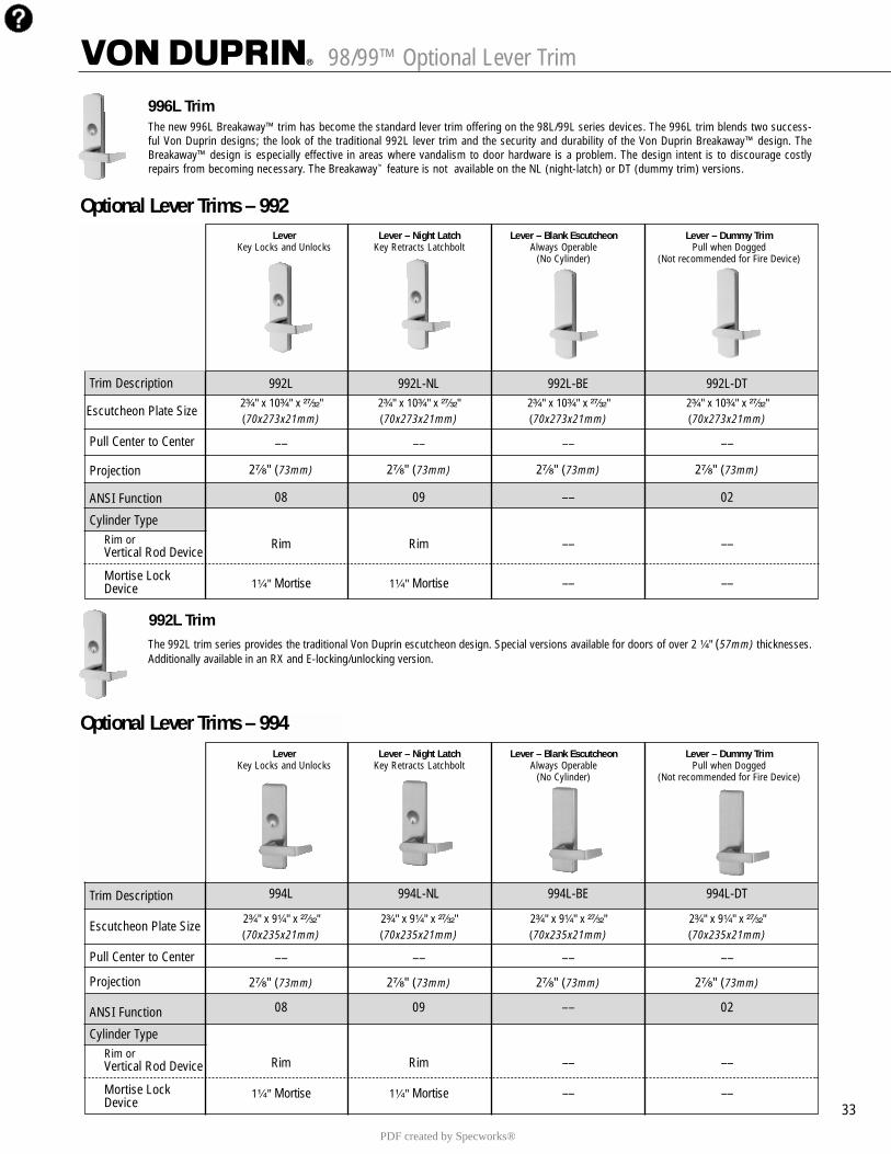
98/99™ Optional Lever Trim
33
Lever Lever – Night Latch Lever – Blank Escutcheon Lever – Dummy TrimKey Locks and Unlocks Key Retracts Latchbolt Always Operable Pull when Dogged
(No Cylinder) (Not recommended for Fire Device)
Trim Description
Escutcheon Plate Size
Pull Center to Center
Projection
ANSI Function
Cylinder TypeRim or Vertical Rod Device
Mortise Lock Device
992L 992L-NL 992L-BE 992L-DT2³�₄" x 10³�₄" x ²⁷�₃₂" 2³�₄" x 10³�₄" x ²⁷�₃₂" 2³�₄" x 10³�₄" x ²⁷�₃₂" 2³�₄" x 10³�₄" x ²⁷�₃₂"(70x273x21mm) (70x273x21mm) (70x273x21mm) (70x273x21mm)
–– –– –– ––
2⁷�₈" (73mm) 2⁷�₈" (73mm) 2⁷�₈" (73mm) 2⁷�₈" (73mm)
08 09 –– 02
Rim Rim –– ––
1¹�₄" Mortise 1¹�₄" Mortise –– ––
Optional Lever Trims – 992
Optional Lever Trims – 994Lever Lever – Night Latch Lever – Blank Escutcheon Lever – Dummy Trim
Key Locks and Unlocks Key Retracts Latchbolt Always Operable Pull when Dogged(No Cylinder) (Not recommended for Fire Device)
Trim Description
Escutcheon Plate Size
Pull Center to Center
Projection
ANSI Function
Cylinder TypeRim or Vertical Rod Device
Mortise Lock Device
994L 994L-NL 994L-BE 994L-DT
2³�₄" x 9¹�₄" x ²⁷�₃₂" 2³�₄" x 9¹�₄" x ²⁷�₃₂" 2³�₄" x 9¹�₄" x ²⁷�₃₂" 2³�₄" x 9¹�₄" x ²⁷�₃₂"(70x235x21mm) (70x235x21mm) (70x235x21mm) (70x235x21mm)
–– –– –– ––
2⁷�₈" (73mm) 2⁷�₈" (73mm) 2⁷�₈" (73mm) 2⁷�₈" (73mm)
08 09 –– 02
Rim Rim –– ––
1¹�₄" Mortise 1¹�₄" Mortise –– ––
The new 996L Breakaway™ trim has become the standard lever trim offering on the 98L/99L series devices. The 996L trim blends two success-ful Von Duprin designs; the look of the traditional 992L lever trim and the security and durability of the Von Duprin Breakaway™ design. TheBreakaway™ design is especially effective in areas where vandalism to door hardware is a problem. The design intent is to discourage costlyrepairs from becoming necessary. The Breakaway™ feature is not available on the NL (night-latch) or DT (dummy trim) versions.
996L Trim
992L TrimThe 992L trim series provides the traditional Von Duprin escutcheon design. Special versions available for doors of over 2 ¹�₄" (57mm) thicknesses.Additionally available in an RX and E-locking/unlocking version.
PDF created by Specworks®
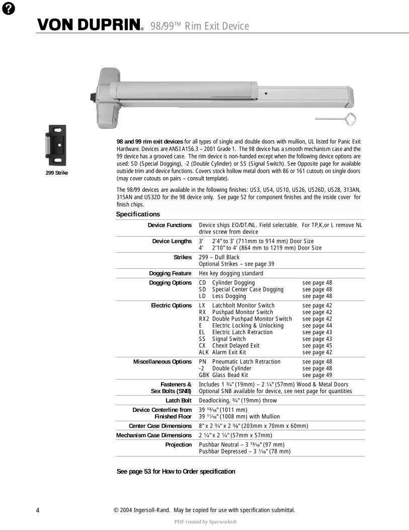
4 © 2004 Ingersoll-Rand. May be copied for use with specification submittal.
98/99™ Rim Exit Device
299 Strike
98 and 99 rim exit devices for all types of single and double doors with mullion, UL listed for Panic ExitHardware. Devices are ANSI A156.3 – 2001 Grade 1. The 98 device has a smooth mechanism case and the99 device has a grooved case. The rim device is non-handed except when the following device options areused: SD (Special Dogging), -2 (Double Cylinder) or SS (Signal Switch). See Opposite page for availableoutside trim and device functions. Covers stock hollow metal doors with 86 or 161 cutouts on single doors(may cover cutouts on pairs – consult template).
The 98/99 devices are available in the following finishes: US3, US4, US10, US26, US26D, US28, 313AN,315AN and US32D for the 98 device only. See page 52 for component finishes and the inside cover forfinish chips.
Specifications
Device Functions Device ships EO/DT/NL. Field selectable. For TP,K,or L remove NL drive screw from device
Device Lengths 3’ 2’4" to 3’ (711mm to 914 mm) Door Size4’ 2’10" to 4’ (864 mm to 1219 mm) Door Size
Strikes 299 – Dull BlackOptional Strikes – see page 39
Dogging Feature Hex key dogging standard
Dogging Options CD Cylinder Dogging see page 48 SD Special Center Case Dogging see page 48 LD Less Dogging see page 48
Electric Options LX Latchbolt Monitor Switch see page 42 RX Pushpad Monitor Switch see page 42 RX2 Double Pushpad Monitor Switch see page 42E Electric Locking & Unlocking see page 44EL Electric Latch Retraction see page 43 SS Signal Switch see page 43 CX Chexit Delayed Exit see page 45ALK Alarm Exit Kit see page 42
Miscellaneous Options PN Pneumatic Latch Retraction see page 48 -2 Double Cylinder see page 48 GBK Glass Bead Kit see page 49
Fasteners & Includes 1 ³�₄" (19mm) – 2 ¹�₄" (57mm) Wood & Metal DoorsSex Bolts (SNB) Optional SNB available for device, see next page for quantities
Latch Bolt Deadlocking, ³�₄" (19mm) throw
Device Centerline from 39 ¹³�₁₆" (1011 mm)Finished Floor 39 ¹¹�₁₆" (1008 mm) with Mullion
Center Case Dimensions 8" x 2 ³�₄" x 2 ³�₈" (203mm x 70mm x 60mm)
Mechanism Case Dimensions 2 ¹�₄" x 2 ¹�₄" (57mm x 57mm)
Projection Pushbar Neutral – 3 ¹³�₁₆" (97 mm)Pushbar Depressed – 3 ¹�₁₆" (78 mm)
See page 53 for How to Order specification
PDF created by Specworks®
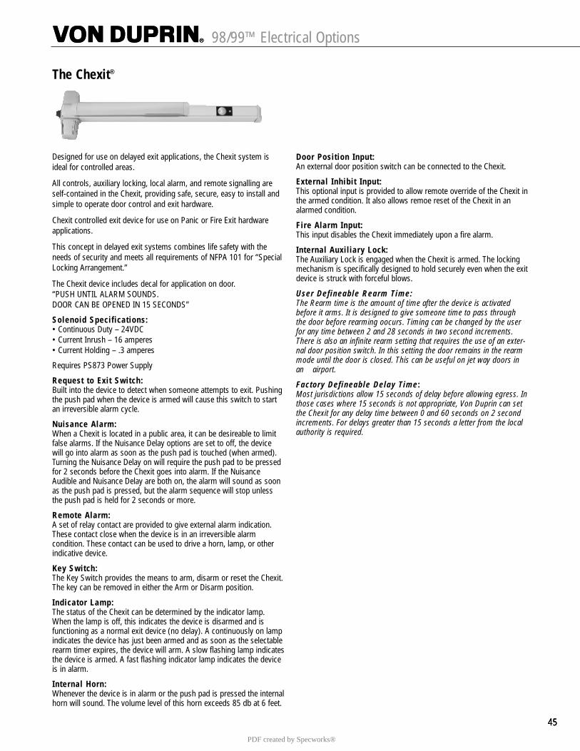
454545
98/99™ Electrical Options
The Chexit®
Designed for use on delayed exit applications, the Chexit system isideal for controlled areas.
All controls, auxiliary locking, local alarm, and remote signalling areself-contained in the Chexit, providing safe, secure, easy to install andsimple to operate door control and exit hardware.
Chexit controlled exit device for use on Panic or Fire Exit hardwareapplications.
This concept in delayed exit systems combines life safety with theneeds of security and meets all requirements of NFPA 101 for “SpecialLocking Arrangement.”
The Chexit device includes decal for application on door. “PUSH UNTIL ALARM SOUNDS. DOOR CAN BE OPENED IN 15 SECONDS”
Solenoid Specifications:• Continuous Duty – 24VDC• Current Inrush – 16 amperes• Current Holding – .3 amperes
Requires PS873 Power Supply
Request to Exit Switch:Built into the device to detect when someone attempts to exit. Pushingthe push pad when the device is armed will cause this switch to startan irreversible alarm cycle.
Nuisance Alarm:When a Chexit is located in a public area, it can be desireable to limitfalse alarms. If the Nuisance Delay options are set to off, the devicewill go into alarm as soon as the push pad is touched (when armed).Turning the Nuisance Delay on will require the push pad to be pressedfor 2 seconds before the Chexit goes into alarm. If the NuisanceAudible and Nuisance Delay are both on, the alarm will sound as soonas the push pad is pressed, but the alarm sequence will stop unlessthe push pad is held for 2 seconds or more.
Remote Alarm:A set of relay contact are provided to give external alarm indication.These contact close when the device is in an irreversible alarmcondition. These contact can be used to drive a horn, lamp, or otherindicative device.
Key Switch:The Key Switch provides the means to arm, disarm or reset the Chexit.The key can be removed in either the Arm or Disarm position.
Indicator Lamp:The status of the Chexit can be determined by the indicator lamp.When the lamp is off, this indicates the device is disarmed and isfunctioning as a normal exit device (no delay). A continuously on lampindicates the device has just been armed and as soon as the selectablerearm timer expires, the device will arm. A slow flashing lamp indicatesthe device is armed. A fast flashing indicator lamp indicates the deviceis in alarm.
Internal Horn:Whenever the device is in alarm or the push pad is pressed the internalhorn will sound. The volume level of this horn exceeds 85 db at 6 feet.
Door Position Input:An external door position switch can be connected to the Chexit.
External Inhibit Input:This optional input is provided to allow remote override of the Chexit inthe armed condition. It also allows remoe reset of the Chexit in analarmed condition.
Fire Alarm Input:This input disables the Chexit immediately upon a fire alarm.
Internal Auxiliary Lock:The Auxiliary Lock is engaged when the Chexit is armed. The lockingmechanism is specifically designed to hold securely even when the exitdevice is struck with forceful blows.
User Defineable Rearm Time:The Rearm time is the amount of time after the device is activatedbefore it arms. It is designed to give someone time to pass throughthe door before rearming oocurs. Timing can be changed by the userfor any time between 2 and 28 seconds in two second increments.There is also an infinite rearm setting that requires the use of an exter-nal door position switch. In this setting the door remains in the rearmmode until the door is closed. This can be useful on jet way doors inan airport.
Factory Defineable Delay Time:Most jurisdictions allow 15 seconds of delay before allowing egress. Inthose cases where 15 seconds is not appropriate, Von Duprin can setthe Chexit for any delay time between 0 and 60 seconds on 2 secondincrements. For delays greater than 15 seconds a letter from the localauthority is required.
PDF created by Specworks®

98/99™ Rim Exit Device Standard Trim
5
Exit only Dummy Trim Night Latch Night LatchPull when Dogged Key Retracts Latchbolt Key Retracts Latchbolt
Optional Pull Required
Product Description
Trim Description
Escutcheon Plate Size
Pull Center to Center
Projection
ANSI Function
Cylinder Type
Optional Trim(See pages 32 – 34)
Optional #425 Sex Bolt Quantity for Device
98EO 98DT 98NL 98NL-OP99EO 99DT 99NL 99NL-OP
110NL-MD110NL-WD
3" x 14³�₁₆" x ³�₃₂" 3" x 14³�₁₆" x ³�₃₂"(76x360x2mm) (76x360x2mm)
–– 5¹�₂" (140mm) 5¹�₂" (140mm) ––
–– 2" (51mm) 2" (51mm) ––
01 02 03 03
–– –– Rim Rim
x990EO x991K-DT x991K-NLx992EO x992L-DT x992L-NLx994EO x994L-DT x994L-NLx996EO x996L-DT x996L-NL
x696DT x696NLx697DT x697NL
6 2 2 6
–– 990DT 990NL-R/V
–– ––
Lever Lever – Night Latch Lever – Blank Escutcheon Lever Dummy TrimKey Locks & Unlocks Key Retracts Latchbolt Always operable Pull when Dogged
(No Cylinder)
Product Description
Trim Description
Escutcheon Plate Size
Pull Center to Center
Projection
ANSI Function
Cylinder Type
Optional Trim(See pages 32 – 34)
Optional #425 Sex Bolt Quantity for Device
98L 98L-NL 98L-BE 98L-DT99L 99L-NL 99L-BE 99L-DT
996L-R/V 996L-NL-R/V 996L-BE-R/V 996L-DT-R/V
2³�₄" x 10³�₄" x ²⁷�₃₂" 2³�₄" x 10³�₄" x ²⁷�₃₂" 2³�₄" x 10³�₄" x ²⁷�₃₂" 2³�₄" x 10³�₄" x ²⁷�₃₂"(70x273x21mm) (70x273x21mm) (70x273x21mm) (70x273x21mm)
–– –– –– ––
2⁷�₈" (73mm) 2⁷�₈" (73mm) 2⁷�₈" (73mm) 2⁷�₈" (73mm)
08 09 –– 02
Rim Rim –– ––
x992L x992L-NL x992L-BE x992L-DTx994L x994L-NL x994L-BE x994L-DT
2 2 2 2
For optional trims and functions see pages 32-34PDF created by Specworks®
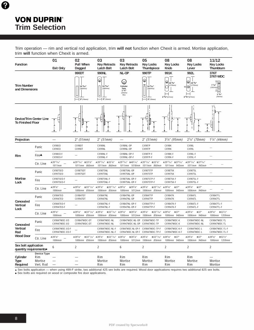
Trim Selection T
8
01 02 03 03 05 08 08 11/12Function Pull When Key Retracts Key Retracts Key Locks Key Locks Key Locks Key Locks
Exit Only Dogged Latch Bolt Latch Bolt Thumbpiece Knob Lever Thumbturn990DT 990NL NL-OP 990TP 991K 992L 376T
376T-WDC
Trim Numberand Dimensions
Device/Trim Center LineTo Finished Floor
Projection — 29 (51mm) 29 (51mm) — 29 (51mm) 33/49 (95mm) 23/49 (70mm) 13/49 (44mm)
Panic CX98EO CX98DT CX98NL CX98NL-OP CX98TP CX98K CX98L—CX99EO CX99DT CX99NL CX99NL-OP CX99TP CX99K CX99L
Rim FireG CX98EO-F — CX98NL-F CX98NL-OP-F CX98TP-F CX98K-F CX98L-F—CX99EO-F CX99NL-F CX99NL-OP-F CX99TP-F CX99K-F CX99L-F
Ctr. Line 3913/169 — 3913/169 337/89 3913/169 337/89 3913/169 401/169 3913/169 337/89 3913/169 373/169 3913/169 373/169— —1011mm 1011mm 860mm 1011mm 860mm 1011mm 1018mm 1011mm 860mm 1011mm 945mm 1011mm 945mm
Panic CX9875EO CX9875DT CX9875NL CX9875NL-OP CX9875TP CX9875K CX9875L—CX9975EO CX9975DT CX9975NL CX9975NL-OP CX9975TP CX9975K CX9975L
Mortise Fire CX9875EO-F — CX9875NL-F CX9875NL-OP-F CX9875TP-F CX9875K-F CX9875L-F—Lock CX9975EO-F CX9975NL-F CX9975NL-OP-F CX9975TP-F CX9975K-F CX9975L-F
Ctr. Line 395/89 — 395/89 3311/169 395/89 3311/169 395/89 397/89 395/89 3311/169 395/89 379 395/89 379— —1006mm 1006mm 856mm 1006mm 856mm 1006mm 1012mm 1006mm 856mm 1006mm 940mm 1006mm 940mm
Panic CX9847EO CX9847DT CX9847NL CX9847NL-OP CX9847TP CX9847K CX9847L CX9847TL
ConcealedCX9947EO CX9947DT CX9947NL CX9947NL-OP CX9947TP CX9947K CX9947L CX9947TL
Vertical Fire CX9847EO-F — CX9847NL-F CX9847NL-OP-F CX9847TP-F CX9847K-F CX9847L-F CX9847TL-F
LockCX9947EO-F CX9947NL-F CX9947NL-OP-F CX9947TP-F CX9947K-F CX9947L-F CX9947TL-F
Ctr. Line 395/89 — 395/89 3311/169 395/89 3311/169 395/89 397/89 395/89 3311/169 395/89 379 395/89 379 395/89 531/29
1006mm 1006mm 856mm 1006mm 856mm 1006mm 1012mm 1006mm 856mm 1006mm 940mm 1006mm 940mm 1006mm 1359mm
Panic CX9847WDC-EO CX9847WDC-DT CX9847WDC-NL CX9847WDC-NL-OP CX9847WDC-TP CX9847WDC-K CX9847WDC-NL CX9847WDC-TL
Concealed CX9947WDC-EO CX9947WDC-DT CX9947WDC-NL CX9947WDC-NL-OP CX9947WDC-TP CX9947WDC-K CX9947WDC-NL CX9947WDC-TL
Vertical Fire CX9847WDC-EO-F — CX9847WDC-NL-F CX9847WDC-NL-OP-F CX9847WDC-TP-F CX9847WDC-K-F CX9847WDC-L CX9847WDC-TL-FRod CX9947WDC-EO-F CX9947WDC-NL-F CX9947WDC-NL-OP-F CX9947WDC-TP-F CX9947WDC-K-F CX9947WDC-L CX9947WDC-TL-F
Wood DoorCtr. Line 395/89 — 395/89 3311/169 395/89 3311/169 395/89 397/89 395/89 3311/169 395/89 379 395/89 379 395/89 531/29
1006mm 1006mm 856mm 1006mm 856mm 1006mm 1012mm 1006mm 856mm 1006mm 940mm 1006mm 940mm 1006mm 1359mm
Sex bolt application 6 2 2 6 2 2 2 2quantity requirementsII
Device Type
Cylinder Rim — — Rim Rim Rim Rim Rim —Type Mortise — — Mortise Mortise Mortise Mortise Mortise MortiseRequired Vert. Rod — — Rim Rim Rim Rim Rim MortiseG Sex bolts application — when using 499-F strike, two additional 425 sex bolts are required. Wood door applications requires two additional 825 sex bolts.I Sex bolts are required on wood or composite fire door applications.
A A B A B A B A B A B A B
A A B A B A B A B A B A B
A A B A B A B A B A B A B A B
A A B A B A B A B A B A B A B
14 3/16"(360mm)
3"(76mm)
14 3/16"(360mm)
3"(76mm)
M
N
14 3/16"(360mm)
3"(76mm)2 5/8"(67mm)
10 5/8"(270mm)
1 1/4"(32mm)
Rim
CylinderOnly
10 5/8"(270mm)
2 5/8"(67mm)1 3/4"
(44mm)
7 1/2"(191mm)
AM
N
B
M
N
A
M
N
A
M
N
A
M
N
BM
N
B
M
N
AM
N
B
M
N
A
M
N
B
M
N
A
M
N
B M
N
A
M
N
B
Trim operation — rim and vertical rod application, trim will not function when Chexit is armed. Mortise application,trim will function when Chexit is armed.
PDF created by Specworks®
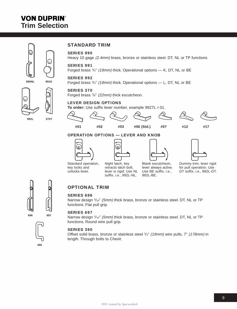
Trim Selection T
9
STANDARD TRIM
SERIES 990Heavy 10 gage (2.4mm) brass, bronze or stainless steel. DT, NL or TP functions
SERIES 991Forged brass 3/49 (19mm) thick. Operational options — K, DT, NL or BE
SERIES 992Forged brass 3/49 (19mm) thick. Operational options — L, DT, NL or BE
SERIES 370Forged brass 7/89 (22mm) thick escutcheon.
LEVER DESIGN OPTIONSTo or der: Use suffix lever number, example 9927L201.
#01 #02 #03 #06 (Std.) #07 #12 #17
OPERATION OPTIONS — LEVER AND KNOB
OPTIONAL TRIM
SERIES 696Narrow design 3/169 (5mm) thick brass, bronze or stainless steel. DT, NL or TPfunctions. Flat pull grip.
SERIES 697Narrow design 3/169 (5mm) thick brass, bronze or stainless steel. DT, NL or TPfunctions. Round wire pull grip.
SERIES 390Offset solid brass, bronze or stainless steel 3/49 (19mm) wire pulls, 79 (178mm) inlength. Through bolts to Chexit.
Standard operation, Night latch, key Blank escutcheon, Dummy trim, lever rigidkey locks and retracts latch bolt, lever always active. for pull operation. Useunlocks lever. lever is rigid. Use NL Use BE suffix, i.e., DT suffix, i.e., 992L-DT.
suffix, i.e., 992L-NL. 992L-BE.
990NL 991K
992L 370T
696 697
390
PDF created by Specworks®
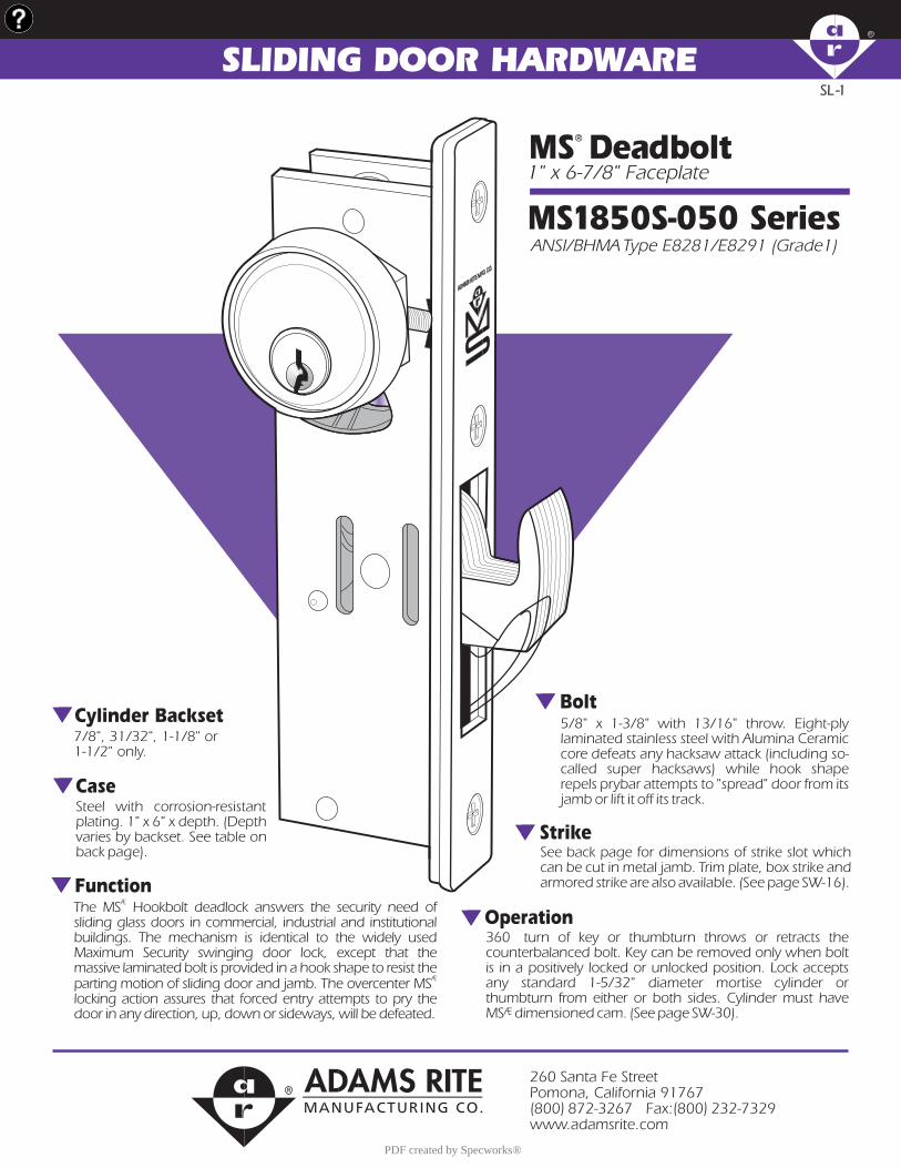
SL -1SL -1
SLIDING DOOR HARDWARE
1" x 6-7/8" FaceplateMS Deadbolt
ANSI/BHMA Type E8281/E8291 (Grade1)MS1850S-050 Series
Steel with corrosion-resistant plating. 1" x 6" x depth. (Depth varies by backset. See table on back page).
Case
Cylinder Backset
360 turn of key or thumbturn throws or retracts the counterbalanced bolt. Key can be removed only when bolt is in a positively locked or unlocked position. Lock accepts any standard 1-5/32" diameter mortise cylinder or thumbturn from either or both sides. Cylinder must have MS dimensioned cam. (See page SW-30).Æ
7/8", 31/32", 1-1/8" or 1-1/2" only.
FunctionThe MS Hookbolt deadlock answers the security need of sliding glass doors in commercial, industrial and institutional buildings. The mechanism is identical to the widely used Maximum Security swinging door lock, except that the massive laminated bolt is provided in a hook shape to resist the parting motion of sliding door and jamb. The overcenter MS locking action assures that forced entry attempts to pry the door in any direction, up, down or sideways, will be defeated.
Æ
Æ
See back page for dimensions of strike slot which can be cut in metal jamb. Trim plate, box strike and armored strike are also available. (See page SW-16).
5/8" x 1-3/8" with 13/16" throw. Eight-ply laminated stainless steel with Alumina Ceramic core defeats any hacksaw attack (including so-called super hacksaws) while hook shape repels prybar attempts to "spread" door from its jamb or lift it off its track.
Bolt
Strike
Operation
260 Santa Fe StreetPomona, California 91767(800) 872-3267 Fax:(800) 232-7329www.adamsrite.com
PDF created by Specworks®

MS1850S-050 DeadboltR
000810 SL MS1850S-050 ©2000 ADAMS RITE MANUFACTURING CO.
DIMENSIONS INSTALLATION
OPTIONSCylinder backset and faceplate finish and shape (radiused, flat or bevel cross-section to match door nose) must be specified.
HOW TO ORDER
Backset1
234
7/831/32"1-1/8"1-1/2"
Handing
555650
LH or RHRRH or LHRNon-Handed*
Faceplate Shape1850S1851S1851SW1852S
FlatRadiusRadius w/wístripBevel
MS1850S 628250
Specify quantity and the following information. Order related hardware separately.
Nominal, subject to tolerance extremes.
INCHESMILLIMETERS
Individually boxed with machine screws for mounting. Cylinders and/or thumbturn available at extra cost. Shipping weight: 1-1/2 lbs. Also available in a 25 unit pack for volume users.
STANDARD PACKAGEFinish
628313335
Satin Aluminum"Bronze" AnodizedBlack Anodized
Stile Preparation
BACKSET "A"
7/8"
31/32"
1-1/8"
1-1/2"
22.0
24.6
28.6
38.1
1.57
1.63
1.78
2.25
39.9
41.4
45.2
57.1
ARMOREDFACEPLATE
1" x 6-7/8"
FLAT MS1850S-050
RADIUS MS1851S-050
LH BEVEL MS1852S-055
RH BEVEL MS1852S-056
RADIUS w/WEATHERSTRIPMS1851SW-050
*Any flat or radius face.
.6215.7
1.0025.4
.8822.4
"A" SHOWN WITHFLAT FACEPLATE
1.2531.7 DIA. HOLE
CUTOUT TOLERANCE:
+ .015_ .000
+ 0.38_ 0.00
6.885174.88
1.59440.49
1.01025.65
.156 R3.97
(4 PLCS.)
BACKSET
STILECL
MS1850S-050 Series locks are operable by any standard 1-5/32" diameter mortise cylinder with special MS cam dimensioned as shown. Cylinders with MS cams can be readily obtained from most cylinder manufacturers. See page SW-30 for cylinder make and trim ring information.
®
®
Cylinder Cam
CYLINDERCL
.1824.62
.80020.32
.120 R 3.05
CAM TOLERANCE:+_+_ 0.13
.005
CYLINDERCL
CL
FLAT
RADIUS
CL
HOW BACKSETIS MEASURED
Lock & CylinderInstallation
.9223.4
2.1955.6
LC
.256.3
.6817.3
1.9449.3
LCLOCK & STILE CYLINDER
STRIKE CUTOUT
BEVEL
CL
6.00152.4
BACKSET MEASUREDAT CENTERLINE OFSTILE NOSE
6.88174.7
6.81173.0
.348.4
.225.6
.8120.6
.256.3
6.38162.0
.5413.7
.6215.7
PDF created by Specworks®
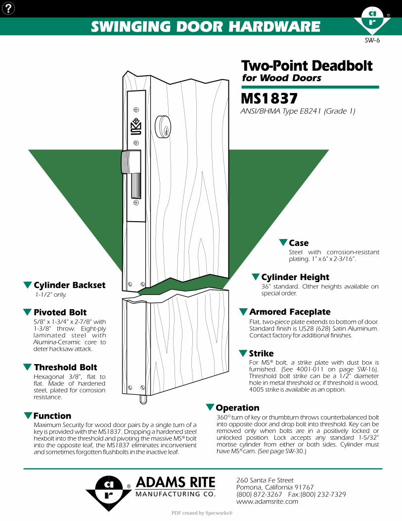
SW-6SW-6
Steel with corrosion-resistant plating. 1" x 6" x 2-3/16".
Case
SWINGING DOOR HARDWARE
Operation360 turn of key or thumbturn throws counterbalanced bolt into opposite door and drop bolt into threshold. Key can be removed only when bolts are in a positively locked or unlocked position. Lock accepts any standard 1-5/32" mortise cylinder from either or both sides. Cylinder must have MS cam. (See page SW-30.)
o
Æ
Pivoted Bolt5/8" x 1-3/4" x 2-7/8" with 1-3/8" throw. Eight-ply laminated steel with Alumina-Ceramic core to deter hacksaw attack.
Armored FaceplateFlat, two-piece plate extends to bottom of door. Standard finish is US28 (628) Satin Aluminum. Contact factory for additional finishes.
Threshold BoltHexagonal 3/8", flat to flat. Made of hardened steel, plated for corrosion resistance.
StrikeFor MS bolt, a strike plate with dust box is furnished. (See 4001-011 on page SW-16). Threshold bolt strike can be a 1/2" diameter hole in metal threshold or, if threshold is wood, 4005 strike is available as an option.
®
Cylinder Backset1-1/2" only.
Cylinder Height36" standard. Other heights available on special order.
FunctionMaximum Security for wood door pairs by a single turn of a key is provided with the MS1837. Dropping a hardened steel hexbolt into the threshold and pivoting the massive MS bolt into the opposite leaf, the MS1837 eliminates inconvenient and sometimes forgotten flushbolts in the inactive leaf.
®
ANSI/BHMA Type E8241 (Grade 1)MS1837for Wood DoorsTwo-Point Deadbolt
260 Santa Fe StreetPomona, California 91767(800) 872-3267 Fax:(800) 232-7329www.adamsrite.com
PDF created by Specworks®
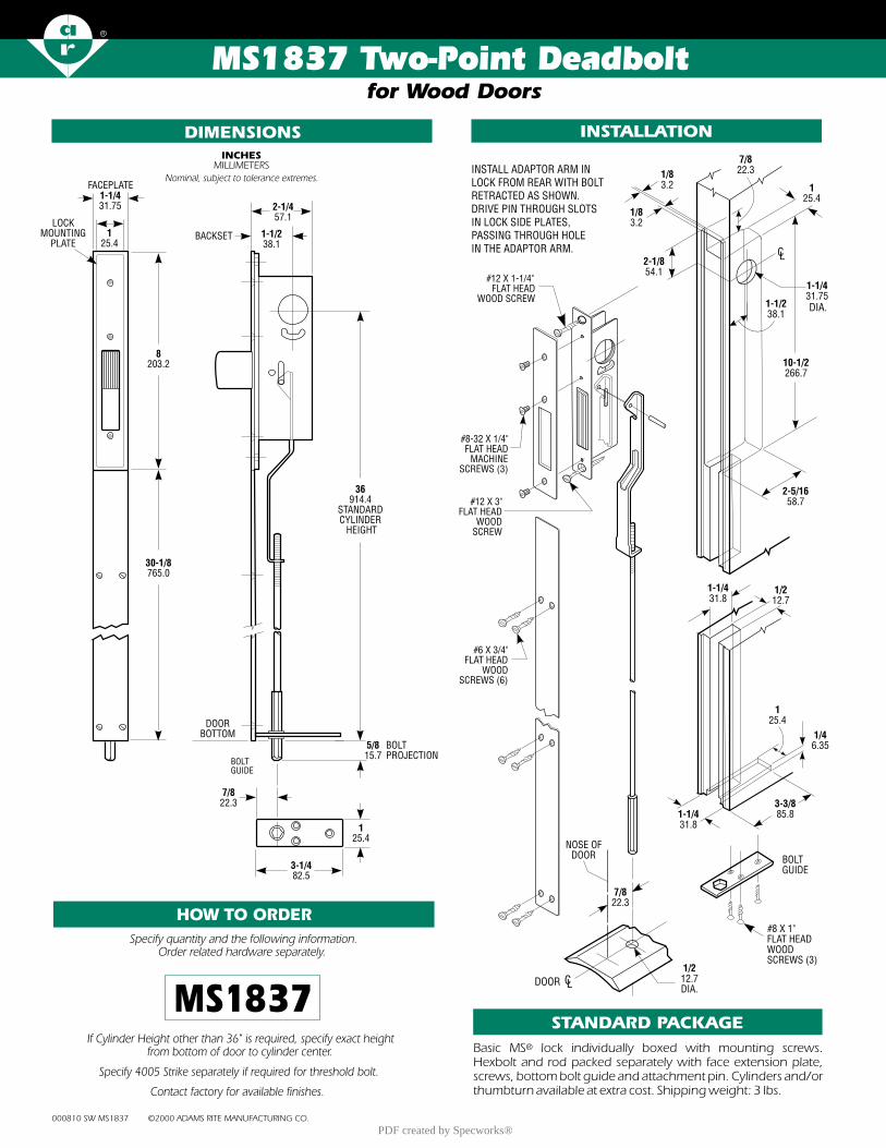
MS1837 Two-Point Deadbolt
000810 SW MS1837 ©2000 ADAMS RITE MANUFACTURING CO.
DIMENSIONS INSTALLATION
HOW TO ORDER
MS1837
Specify quantity and the following information. Order related hardware separately.
Basic MS lock individually boxed with mounting screws. Hexbolt and rod packed separately with face extension plate, screws, bottom bolt guide and attachment pin. Cylinders and/or thumbturn available at extra cost. Shipping weight: 3 lbs.
®
STANDARD PACKAGEIf Cylinder Height other than 36" is required, specify exact height
from bottom of door to cylinder center.
Specify
4005 Strike separately if required for threshold bolt.
Contact factory
for
available
finishes.
for Wood Doors
5/815.7
BOLTPROJECTION
DOORBOTTOM
3-1/482.5
7/822.3
125.4
BACKSET 1-1/238.1
2-1/457.1
36914.4
STANDARDCYLINDER HEIGHT
LOCK MOUNTING
PLATE1
25.4
FACEPLATE1-1/431.75
8203.2
30-1/8765.0
Nominal, subject to tolerance extremes.
INCHESMILLIMETERS
BOLTGUIDE
INSTALL ADAPTOR ARM IN LOCK FROM REAR WITH BOLT RETRACTED AS SHOWN. DRIVE PIN THROUGH SLOTS IN LOCK SIDE PLATES, PASSING THROUGH HOLE IN THE ADAPTOR ARM.
3-3/885.81-1/4
31.8
1-1/431.8
1/212.7
1/46.35
BOLT GUIDE
#8 X 1 FLAT HEADWOOD SCREWS (3)
"
125.4
CL
125.4
1-1/431.75
7/822.3
1/83.2
1/83.2
2-1/854.1
10-1/2266.7
2-5/1658.7
1-1/238.1
DIA.
1/212.7DIA.
CLDOOR
NOSE OFDOOR
7/822.3
#8-32 X 1/4 FLAT HEAD
MACHINE SCREWS (3)
"
#12 X 1-1/4" FLAT HEAD
WOOD SCREW
#6 X 3/4" FLAT HEAD
WOOD SCREWS (6)
#12 X 3" FLAT HEAD
WOOD SCREW
PDF created by Specworks®
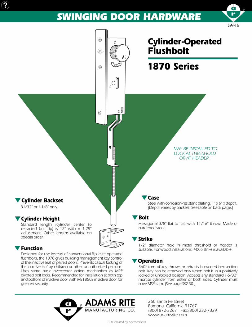
SW-16SW-16
Steel with corrosion-resistant plating. 1" x 6" x depth. (Depth varies by backset. See table on back page.)
Case
Standard length (cylinder center to retracted bolt tip) is 12" with +_ 1.25" adjustment. Other lengths available on special order.
Cylinder Height
SWINGING DOOR HARDWARE
Operation360 turn of key throws or retracts hardened hex-section bolt. Key can be removed only when bolt is in a positively locked or unlocked position. Accepts any standard 1-5/32" mortise cylinder from either or both sides. Cylinder must have MS cam. (See page SW-30.)
o
®�
BoltHexagonal 3/8" flat to flat, with 11/16" throw. Made of hardened steel.
Strike1/2" diameter hole in metal threshold or header is suitable. For wood installations, 4005 strike is available.
Cylinder Backset31/32" or 1-1/8" only.
FunctionDesigned for use instead of conventional flip-lever operated flushbolts, the 1870 gives building management key control of the inactive leaf of paired doors. Prevents casual locking of the inactive leaf by children or other unauthorized persons. Uses same basic overcenter action mechanism as MS pivoted bolt locks. Recommended for installation at both top and bottom of inactive door with MS1850S in active door for greatest security.
®
Cylinder-OperatedFlushbolt
1870 Series
MAY BE INSTALLED TO LOCK AT THRESHOLD
OR AT HEADER.
260 Santa Fe StreetPomona, California 91767(800) 872-3267 Fax:(800) 232-7329www.adamsrite.com
PDF created by Specworks®

1870 Series Flushbolt
000810 SW 1870 SERIES ©2000 ADAMS RITE MANUFACTURING CO.
DIMENSIONS INSTALLATION
Nominal, subject to tolerance extremes.
INCHESMILLIMETERS
Basic lock mechanism boxed with actuator arm attached, rod/bolt assembly unattached. Stainless steel bolt guide, mounting screws and installation instructions included. Cylinders available at extra cost. Shipping weight: 1-1/4 lbs.
STANDARD PACKAGE
BACKSET "A"
ARMOREDFACEPLATE
1" x 6-7/8"
31/32"
1-1/8"
24.6
28.6
FLAT 1870
RADIUS 1871
LH BEVEL 1872-05
RH BEVEL 1872-06
RADIUS w/WEATHERSTRIP1871W
1.63
1.78
41.4
45.2
HOW TO ORDER
Backset
23
31/32"1-1/8"
Handing
LH or RHRRH or LHRNon-Handed*
560
Faceplate Shape
1870187118721871W
FlatRadiusBevelRadius w/strip
1871- 20 - 628
Specify quantity and the following information. Order related hardware separately.
Finish
628313335
Satin AluminumBronze AnodizedBlack Anodized
*Any flat or radius face.
.8822.3
"A"
CL1.025.4
BACKSET MEASUREDAT CENTERLINE OFSTILE NOSE
.256.3
6.38162.0
6.87174.6
.6917.5 THROW
1.3434.0
6.00152.0
12.00*304.0
*STANDARD LENGTH OTHER LENGTHS AVAILABLE ON SPECIAL ORDER
Lock & Cylinder Installation
Stile Preparation
FOR INSTALLATION LOCKING THRESHOLDINVERT FOR HEADER LOCKING BOLT
CL
.5012.7DIA.
.8722.2
1.59440.4
1.0125.6
6.885174.8
1.2531.7
DRILL & C'SK FOR #10-32
FLAT HEAD SCREWS
DIA.
.1563.9 R
(4 PLCS)
THRESHOLD
.6817.4
.56214.2
12.00304.0
.5714.6LCSTILE
CUTOUT TOLERANCE:
+ .015_ .000
+ 0.38_ 0.0
1870 Series locks are operable by any standard 1-5/32" diameter mortise c y l i n d e r w i t h special MS cam dimensioned as shown. Cylinders with MS cams can be readily obtained from most cylinder manufacturers. See page SW-30 for cylinder make and trim ring information.
®
®
Cylinder Cam
CYLINDERCL
.1824.62
.80020.32
.120 R 3.05
CAM TOLERANCE:
+_+_ .13
.005
CYLINDER
HOW BACKSETIS MEASURED:
CL
CL
FLAT
RADIUS
BEVEL
CL
CL
NOTE: MACHINE SCREWS ARE FURNISHED.
FOR SECURITY, INSTALL BOLT GUIDE FROM
INTERIOR OF DOOR.
PDF created by Specworks®
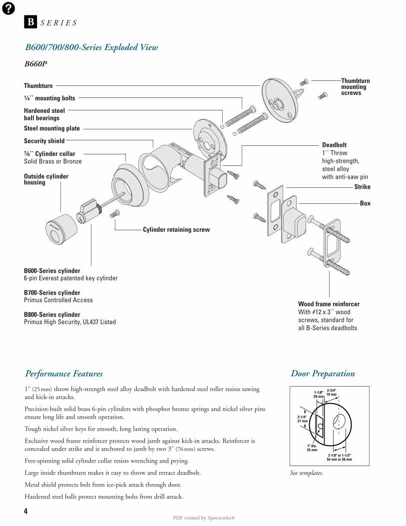
4
B600/700/800-Series Exploded View
S E R I E SB
Performance Features
1˝ (25mm) throw high-strength steel alloy deadbolt with hardened steel roller resists sawing and kick-in attacks.
Precision-built solid brass 6-pin cylinders with phosphor bronze springs and nickel silver pinsensure long life and smooth operation.
Tough nickel silver keys for smooth, long lasting operation.
Exclusive wood frame reinforcer protects wood jamb against kick-in attacks. Reinforcer is concealed under strike and is anchored to jamb by two 3˝ (76mm) screws.
Free-spinning solid cylinder collar resists wrenching and prying.
Large inside thumbturn makes it easy to throw and retract deadbolt.
Metal shield protects bolt from ice-pick attack through door.
Hardened steel balls protect mounting bolts from drill attack.
Door Preparation
See templates.
Hardened steelball bearings
Security shield
Steel mounting plate
Outside cylinderhousing
B600-Series cylinder6-pin Everest patented key cylinder
B700-Series cylinderPrimus Controlled Access
B800-Series cylinderPrimus High Security, UL437 Listed
Cylinder retaining screw
Wood frame reinforcerWith #12 x 3´´ woodscrews, standard forall B-Series deadbolts
Box
Strike
Deadbolt1´´ Throwhigh-strength,steel alloywith anti-saw pin
Thumbturnmountingscrews
⁷�₈´´ Cylinder collarSolid Brass or Bronze
B660P
Thumbturn
¹�₄´´ mounting bolts
PDF created by Specworks®
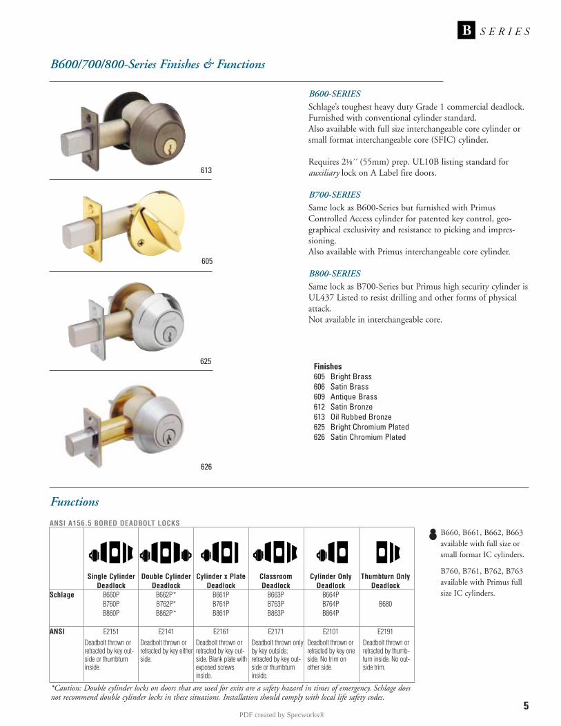
Functions
ANSI A156.5 BORED DEADBOLT LOCKS
Single Cylinder Double Cylinder Cylinder x Plate Classroom Cylinder Only Thumbturn OnlyDeadlock Deadlock Deadlock Deadlock Deadlock Deadlock
Schlage B660P B662P* B661P B663P B664PB760P B762P* B761P B763P B764P B680B860P B862P* B861P B863P B864P
ANSI E2151 E2141 E2161 E2171 E2101 E2191
5
S E R I E SB
B600/700/800-Series Finishes & Functions
B600-SERIESSchlage’s toughest heavy duty Grade 1 commercial deadlock.Furnished with conventional cylinder standard.Also available with full size interchangeable core cylinder orsmall format interchangeable core (SFIC) cylinder.
Requires 2⅛´́ (55mm) prep. UL10B listing standard for auxiliary lock on A Label fire doors.
B700-SERIESSame lock as B600-Series but furnished with PrimusControlled Access cylinder for patented key control, geo-graphical exclusivity and resistance to picking and impres-sioning.Also available with Primus interchangeable core cylinder.
B800-SERIESSame lock as B700-Series but Primus high security cylinder isUL437 Listed to resist drilling and other forms of physicalattack.Not available in interchangeable core.
613
605
625
626
*Caution: Double cylinder locks on doors that are used for exits are a safety hazard in times of emergency. Schlage doesnot recommend double cylinder locks in these situations. Installation should comply with local life safety codes.
Finishes605 Bright Brass606 Satin Brass609 Antique Brass612 Satin Bronze613 Oil Rubbed Bronze625 Bright Chromium Plated626 Satin Chromium Plated
Deadbolt thrown orretracted by key out-side or thumbturninside.
Deadbolt thrown orretracted by key eitherside.
Deadbolt thrown orretracted by key out-side. Blank plate withexposed screwsinside.
Deadbolt thrown onlyby key outside;retracted by key out-side or thumbturninside.
Deadbolt thrown orretracted by key oneside. No trim onother side.
Deadbolt thrown orretracted by thumb-turn inside. No out-side trim.
B660, B661, B662, B663available with full size orsmall format IC cylinders.
B760, B761, B762, B763available with Primus fullsize IC cylinders.
PDF created by Specworks®

SpecificationsApplications: For commercial and institutional buildings wherethe finest in mortise locks are required.
Certifications: L9000: ANSI A156.13 Series 1000,Grade 1 Operational and Security, UL Listed for 3-hourfire door (except L9076 and L9077). With interchangeable corecylinders: Grade 2 Security. L400: ANSI A156.5 Grade 1UL Listed auxiliary lock for 3-hour fire door.
With Concealed Cylinder: A156.13 Grade 1 Operational andSecurity. ANSI/ASTM F476-76 Grade 40, UL Listed.
Exposed Trim:Knobs: #41 and #42 heavy duty wrought brass, bronze or stainlesssteel knobs match in appearance and are equal to D-Series knobs. Levers: Levers are available in forged brass or bronze and caststainless steel. Designs available to match D-Series levers. 93 Lever Design: Extruded brass, bronze or stainless steel.Mediterranean Designs: Forged brass lever and rose designs.Escutcheons: L escutcheons are cold forged brass or bronze andstainless steel. N escutcheons are heavy wrought reinforced brass,bronze and stainless steel. L = 8˝ x 1³⁄₄˝ x ⁷⁄₁₆˝ (203mm x 44mmx 11mm). N = 8˝ x 2⁹⁄₁₆˝ x ⁷⁄₁₆˝ (203mm x 65mm x 11mm). Roses: A = 2¹⁄₈˝ (54mm) diameter wrought brass, bronze or
stainless steel.B = 2⁹⁄₁₆˝ (65mm) diameter wrought brass, bronze or
stainless steel.
Trim Combinations: Available with knob both sides, lever bothsides, or knob x lever with rose or escutcheon both sides.
Keying: 6-pin cylinder with two nickel silver Everestpatented keys standard. Keying options available from factoryare master keying, construction keying, interchangeable core,SFIC and Primus® high security cylinders.
Door Range: 1³⁄₄˝ (44mm) Standard. 1³⁄8˝ (35mm) to 2¹⁄2˝(64mm) Regular parts assembled to order. Over 2¹⁄2˝ (64mm)door ranges vary by function. N escutcheon available for 1³⁄₄˝(44mm) doors standard. 2˝ (51mm) to 2³⁄8˝ (60mm) Regularparts assembled to order. Specify door thickness if other than1³⁄₄˝.
Case Size: 4⁷⁄₁₆˝ x 6¹⁄₁₆˝ x 1˝ (113mm x 154mm x 25mm).
Armored Front: 1¹⁄₄˝ x 8˝ x ⁷⁄₃₂˝ (32mm x 203mm x 6mm)Standard. 1¹⁄₁₆˝ x 8˝ x ⁷⁄₃₂˝ (27mm x 203mm x 6mm) Optional.
Spacing: Knob or lever to cylinder, 3⁷⁄₈˝ (98mm); knob orlever to thumbturn hub, 2¹¹⁄₁₆˝ (68mm).
Deadbolt: 1˝ (25mm) Throw stainless steel.
Latchbolt: ³⁄₄˝ (19mm) Throw stainless steel with anti-frictiontongue.
Backset: 2³⁄₄˝ (70mm) Only.
1
S E R I E SL
PDF created by Specworks®
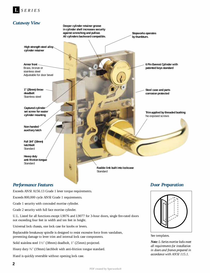
2
S E R I E SL
Performance FeaturesExceeds ANSI A156.13 Grade 1 lever torque requirements.
Exceeds 800,000 cycle ANSI Grade 1 requirements.
Grade 1 security with concealed mortise cylinder.
Grade 2 security with full face mortise cylinder.
U.L. Listed for all functions except L9076 and L9077 for 3-hour doors, single fire-rated doorsnot exceeding four feet in width and ten feet in height.
Universal lock chassis, one lock case for knobs or levers.
Replaceable breakaway spindle is designed to resist excessive force from vandalism,preventing damage to lever trim and internal lock case components.
Solid stainless steel 1¹⁄₂˝ (38mm) deadbolt, 1˝ (25mm) projected.
Heavy duty ³⁄₄˝ (19mm) latchbolt with anti-friction tongue standard.
Hand is quickly reversible without opening lock case.
Door Preparation
Deeper cylinder retainer groovein cylinder shell increases securityagainst wrenching and pullout.All cylinders backward compatible.
High strength steel alloycylinder retainer
Armor frontBrass, bronze orstainless steelAdjustable for door bevel
1” (25mm) throwdeadboltStainless steel
Captured cylinderset screw for easiercylinder mounting
Non-handedauxiliary latch
Full 3/4” (19mm)latchboltStandard
Heavy dutyanti-friction tongueStandard
Fusible link built into lockcaseStandard
Stopworks operatesby thumbturn.
Steel case and partscorrosion protected
Trim applied by threaded bushingNo exposed screws
Cutaway View
See templates.
Note: L-Series mortise locks meetall requirements for installationin doors and frames prepared inaccordance with ANSI 115.1.
6 Pin Everest Cylinder withpatented keys standard
PDF created by Specworks®
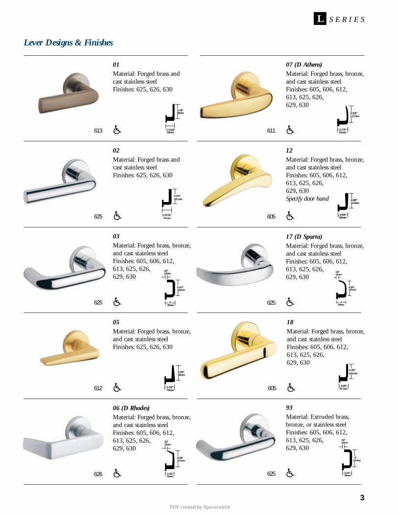
Lever Designs & Finishes
3
S E R I E SL
01Material: Forged brass andcast stainless steelFinishes: 625, 626, 630
02Material: Forged brass andcast stainless steelFinishes: 625, 626, 630
03Material: Forged brass, bronze,and cast stainless steelFinishes: 605, 606, 612, 613, 625, 626, 629, 630
05Material: Forged brass, bronze,and cast stainless steelFinishes: 625, 626, 630
06 (D Rhodes)Material: Forged brass, bronze,and cast stainless steelFinishes: 605, 606, 612, 613, 625, 626, 629, 630
07 (D Athens)Material: Forged brass, bronze,and cast stainless steelFinishes: 605, 606, 612, 613, 625, 626, 629, 630
12Material: Forged brass, bronze,and cast stainless steelFinishes: 605, 606, 612, 613, 625, 626, 629, 630Specify door hand
93Material: Extruded brass,bronze, or stainless steelFinishes: 605, 606, 612, 613, 625, 626, 629, 630
17 (D Sparta)Material: Forged brass, bronze,and cast stainless steelFinishes: 605, 606, 612, 613, 625, 626, 629, 630
613
625
625
612
611
605
625
625
626
2-11/16"64mm
96mm3-7/8"
2-15/16"75 mm
4-3/4"121 mm
4-3/4"121mm
3"76mm
13mm1/2"
2-7/8"73mm
3-3/4"95mm
2-3/4"73mm
13mm1/2"
4-5/8"117mm
2-7/8"75mm
4-5/8"117mm
3-5/8"92mm
4-5/8"117mm
13mm1/2"
3-1/4"76mm
5"127mm
3"76mm
13mm1/2"
4-3/4"121mm
18Material: Forged brass, bronze,and cast stainless steelFinishes: 605, 606, 612, 613, 625, 626, 629, 630
605 2-5/8"
4-7/8"124 mm
67 mm
PDF created by Specworks®

6
S E R I E SL
Escutcheons, Roses, Special Turns & Finishes
Finishes605 Bright Brass606 Satin Brass612 Satin Bronze613 Oil Rubbed Bronze625 Bright Chromium Plated626 Satin Chromium Plated629 Bright Stainless Steel630 Satin Stainless Steel
L FULL FACEMaterial: Cold forged brass,bronze, or stainless steel Finishes: 605, 606, 612, 613, 625, 626, 629, 6308˝ x 1³⁄₄˝ x ⁷⁄₁₆˝(203mm x 44mm x 11mm)
A-WROUGHT ROSE2¹⁄₈˝ (54mm) DiameterAvailable for use on L-Seriesknob and lever designs. Order byletter designation correspondingto the design and diameterdesired.
626611
625
L CONCEALEDMaterial: Cold forged brass,bronze, or stainless steelFinishes: 605, 606, 612, 613, 625, 626, 629, 6308˝ x 1³⁄₄˝ x ⁷⁄₁₆˝
(203mm x 44mm x 11mm)
625
B-WROUGHT ROSE 2⁹⁄₁₆˝ (65mm) DiameterAvailable for use on L-Seriesknob and lever designs.Order by letter designation corresponding to the design and diameter desired.
N ESCUTCHEONMaterial: Heavy wrought reinforced brass, bronze, or stainless steelFinishes: 605, 606, 612, 613, 625, 626, 629, 6308˝ x 2⁹⁄₁₆˝ x ⁷⁄₁₆˝
(203mm x 65mm x 11mm)
626
7/16"11mm
8"203mm
7/16"11mm
8"203mm
7/16"11mm
8"203mm
HOTEL OCCUPANCYINDICATOR 09-611For lock function L9486P, thisunit is used with A or B designroses only. It requires a 1³⁄₈˝ (35mm) cylinder for 1³⁄₄˝(44mm) doors. When orderingseparately, specify finish.
OPTIONAL “EZ” TURNL583-363Available for rose andescutcheon trim. Disability turn (ADA) option to standardthumbturn. Can be used withany thumbturn functionL-Series lock, except L9463 and L463. Specify lock perL583-363 when ordering.
625
625
COIN TURN L283-124For lock functions L9044 andL9444 with rose trim.When ordering separately, specify 09-509 and finish perL283-124.
625
PDF created by Specworks®
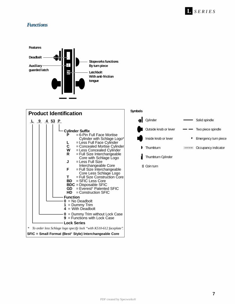
7
S E R I E SL
Functions
Stopworks functionsBy turn piece
LatchboltWith anti-frictiontongue
Deadbolt
Auxiliaryguarded latch
Symbols
Cylinder
Outside knob or lever
Inside knob or lever
Thumbturn
Thumbturn Cylinder
Coin turn
Solid spindle
Two piece spindle
Emergency turn piece
Occupancy indicatorDO NOT DISTURB
Features
Product IdentificationL 9 4 53 P
Cylinder SuffixP = 6-Pin Full Face Mortise
Cylinder with Schlage Logo*L = Less Full Face CylinderC = Concealed Mortise CylinderW = Less Concealed CylinderR = Full Size Interchangeable
Core with Schlage LogoJ = Less Full Size
Interchangeable CoreF = Full Size Interchangeable
Core Less Schlage LogoT = Full Size Construction CoreBD = SFIC Less CoreBDC = Disposable SFICGD = Everest® Patented SFICHD = Construction SFIC
Function0 = No Deadbolt1 = Dummy Trim4 = With Deadbolt0 = Dummy Trim without Lock Case9 = Functions with Lock CaseLock Series
* To order less Schlage logo specify lock “with K510-612 faceplate”.
SFIC = Small Format (Best® Style) Interchangeable Core
PDF created by Specworks®
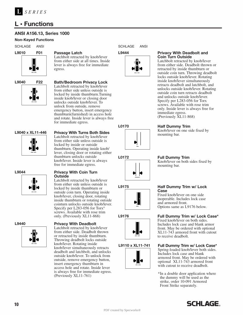
10
L • Functions
S E R I E SL
ANSI A156.13, Series 1000
SCHLAGE ANSI
Non-Keyed Functions
L9010 F01 Passage LatchLatchbolt retracted by knob/leverfrom either side at all times. Insidelever is always free for immediateegress.
SCHLAGE ANSI
L0172 Full Dummy TrimKnob/lever on both sides fixed bymounting bar.
L9175 Half Dummy Trim w/ LockCaseFixed knob/lever on one side inoperable. Includes lock case and armored front. Options same as L9176 below.
L9176 Full Dummy Trim w/ Lock Case*Fixed knob/lever on both sides.Includes lock case and blank armorfront. May be ordered with optionalXL11-743 armored front with cutoutto receive deadbolt.
L9040 F22 Bath/Bedroom Privacy LockLatchbolt retracted by knob/leverfrom either side unless outside islocked by inside thumbturn.Turninginside knob/lever or closing doorunlocks outside knob/lever. Tounlock from outside, remove emergency button, insert emergencythumbturn(furnished) in access holeand rotate. Inside lever is always freefor immediate egress.
L9044 Privacy With Coin TurnOutsideLatchbolt retracted by knob/leverfrom either side unless outside islocked by inside thumbturn or outside coin turn. Operating insideknob/lever, closing door, rotatinginside thumbturn or rotating outsidecointurn unlocks outside knob/lever.Specify per L283-056 for Torx®
screws. Available with rose trimonly. (Previously XL11-868)
L9440 Privacy With DeadboltLatchbolt retracted by knob/leverfrom either side. Deadbolt thrownor retracted by inside thumbturn.Throwing deadbolt locks outsideknob/lever. Rotating insideknob/lever simultaneously retractsdeadbolt and latchbolt, and unlocksoutside knob/lever. To unlock fromoutside, remove emergency button,insert emergency thumbturn inaccess hole and rotate. Inside leveris always free for immediate egress.(Previously XL11-761)
L9444 Privacy With Deadbolt andCoin Turn OutsideLatchbolt retracted by knob/leverfrom either side. Deadbolt thrown orretracted by inside thumbturn oroutside coin turn. Throwing deadboltlocks outside knob/lever. Rotatinginside knob/lever simultaneouslyretracts deadbolt and latchbolt, andunlocks outside knob/lever. Rotatingoutside coin turn retracts deadbolt and unlocks outside knob/lever.Specify per L283-056 for Torxscrews. Available with rose trimonly. Inside lever is always free forimmediate egress. (Previously XL11-868)
L0170 Half Dummy TrimKnob/lever on one side fixed bymounting bar.L9040 x XL11-446 Privacy With Turns Both Sides
Latchbolt retracted by knob/leverfrom either side unless outside islocked by inside or outsidethumbturn. Operating inside knob/lever, closing door or rotating eitherthumbturn unlocks outsideknob/lever. Inside lever is alwaysfree for immediate egress.
L9110 x XL11-741 Full Dummy Trim w/ Lock Case*Spring-loaded knob/lever both sides.Includes lock case and blankarmored front. May be ordered withoptional XL11-743 armored frontwith cutout to receive deadbolt.
*In a double door application wherethe dummy will be used as thestrike, order 10-091 ArmoredFront Strike separately.
PDF created by Specworks®
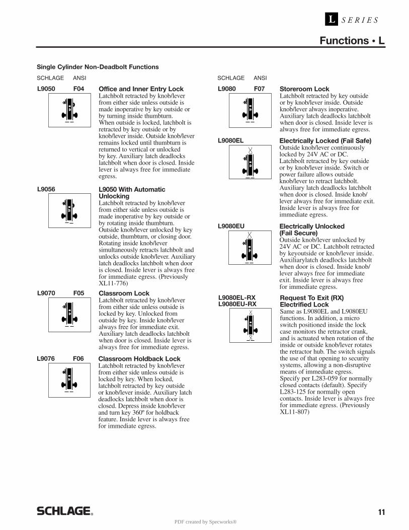
11
Functions • L
S E R I E SL
L9050 F04 Office and Inner Entry LockLatchbolt retracted by knob/leverfrom either side unless outside ismade inoperative by key outside orby turning inside thumbturn. When outside is locked, latchbolt isretracted by key outside or byknob/lever inside. Outside knob/leverremains locked until thumbturn isreturned to vertical or unlocked by key. Auxiliary latch deadlockslatchbolt when door is closed. Insidelever is always free for immediateegress.
L9056 L9050 With AutomaticUnlockingLatchbolt retracted by knob/leverfrom either side unless outside ismade inoperative by key outside orby rotating inside thumbturn. Outside knob/lever unlocked by keyoutside, thumbturn, or closing door.Rotating inside knob/lever simultaneously retracts latchbolt andunlocks outside knob/lever. Auxiliarylatch deadlocks latchbolt when dooris closed. Inside lever is always freefor immediate egress. (PreviouslyXL11-776)
L9070 F05 Classroom LockLatchbolt retracted by knob/leverfrom either side unless outside islocked by key. Unlocked from outside by key. Inside knob/leveralways free for immediate exit.Auxiliary latch deadlocks latchboltwhen door is closed. Inside lever isalways free for immediate egress.
L9076 F06 Classroom Holdback LockLatchbolt retracted by knob/leverfrom either side unless outside islocked by key. When locked,latchbolt retracted by key outside or knob/lever inside. Auxiliary latchdeadlocks latchbolt when door isclosed. Depress inside knob/leverand turn key 360º for holdback feature. Inside lever is always freefor immediate egress.
L9080 F07 Storeroom LockLatchbolt retracted by key outside or by knob/lever inside. Outsideknob/lever always inoperative.Auxiliary latch deadlocks latchboltwhen door is closed. Inside lever isalways free for immediate egress.
L9080EL Electrically Locked (Fail Safe)Outside knob/lever continuouslylocked by 24V AC or DC. Latchbolt retracted by key outside or by knob/lever inside. Switch orpower failure allows outsideknob/lever to retract latchbolt.Auxiliary latch deadlocks latchboltwhen door is closed. Inside knob/lever always free for immediate exit.Inside lever is always free for immediate egress.
SCHLAGE ANSI
Single Cylinder Non-Deadbolt Functions
SCHLAGE ANSI
L9080EU Electrically Unlocked (Fail Secure)Outside knob/lever unlocked by 24V AC or DC. Latchbolt retractedby keyoutside or knob/lever inside.Auxiliarylatch deadlocks latchboltwhen door is closed. Inside knob/lever always free for immediate exit. Inside lever is always free for immediate egress.
L9080EL-RXL9080EU-RX
Request To Exit (RX) Electrified LockSame as L9080EL and L9080EUfunctions. In addition, a micro switch positioned inside the lockcase monitors the retractor crank,and is actuated when rotation of theinside or outside knob/lever rotatesthe retractor hub. The switch signalsthe use of that opening to securitysystems, allowing a non-disruptivemeans of immediate egress. Specify per L283-059 for normallyclosed contacts (default). SpecifyL283-125 for normally open contacts. Inside lever is always freefor immediate egress. (PreviouslyXL11-807)
PDF created by Specworks®
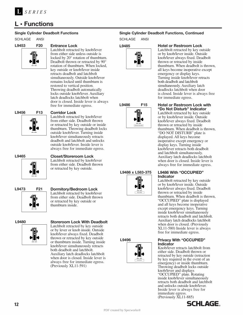
12
L • Functions
S E R I E SL
Single Cylinder Deadbolt Functions
SCHLAGE ANSI SCHLAGE ANSI
Single Cylinder Deadbolt Functions, Continued
L9453 F20 Entrance LockLatchbolt retracted by knob/leverfrom either side unless outside islocked by 20° rotation of thumbturn.Deadbolt thrown or retracted by 90°rotation of thumbturn. When locked,key outside or knob/lever insideretracts deadbolt and latchbolt simultaneously. Outside knob/leverremains locked until thumbturn isrestored to vertical position.Throwing deadbolt automaticallylocks outside knob/lever. Auxiliarylatch deadlocks latchbolt when door is closed. Inside lever is alwaysfree for immediate egress.
L9456 F13 Corridor LockLatchbolt retracted by knob/leverfrom either side. Deadbolt thrown or retracted by key outside or insidethumbturn. Throwing deadbolt locksoutside knob/lever. Turning insideknob/lever simultaneously retractsdeadbolt and latchbolt and unlocksoutside knob/lever. Inside lever isalways free for immediate egress.
L9465 Closet/Storeroom LockLatchbolt retracted by knob/leverfrom either side. Deadbolt thrown or retracted by key outside.
L9473 F21 Dormitory/Bedroom LockLatchbolt retracted by knob/leverfrom either side. Deadbolt thrown or retracted by key outside or thumbturn inside.
L9480 Storeroom Lock With DeadboltLatchbolt retracted by key outside or by lever or knob inside. Outsideknob/lever always fixed. Deadboltthrown or retracted by key outside or thumbturn inside. Turning insideknob/lever simultaneously retractsboth deadbolt and latchbolt. Auxiliary latch deadlocks latchboltwhen door is closed. Inside lever isalways free for immediate egress.(Previously XL11-591)
L9485 Hotel or Restroom LockLatchbolt retracted by key outside or by knob/lever inside. Outsideknob/lever always fixed. Deadboltthrown or retracted by inside thumbturn. When deadbolt is thrown,all keys become inoperative exceptemergency or display keys. Turning inside knob/lever retracts both deadbolt and latchbolt simultaneously. Auxiliary latch deadlocks latchbolt when door is closed. Inside lever is always freefor immediate egress.
DO NOT DISTURB
L9486 F15 Hotel or Restroom Lock with“Do Not Disturb” IndicatorLatchbolt retracted by key outside or by knob/lever inside. Outsideknob/lever always fixed. Deadboltthrown or retracted by inside thumbturn. When deadbolt is thrown,“DO NOT DISTURB” plate is displayed. All keys become inoperative except emergency or display keys. Turning insideknob/lever retracts both deadbolt and latchbolt simultaneously.Auxiliary latch deadlocks latchboltwhen door is closed. Inside lever isalways free for immediate egress.
OCCUPIED
L9486 x L583-375 L9486 With “OCCUPIED”IndicatorLatchbolt retracted by key outside or by knob/lever inside. Outsideknob/lever always fixed. Deadboltthrown or retracted by inside thumbturn. When deadbolt is thrown,“OCCUPIED” plate is displayed and all keys become inoperativeexcept emergency keys. Turninginside knob/lever simultaneouslyretracts both deadbolt and latchbolt.Auxiliary latch deadlocks latchboltwhen door is closed. (PreviouslyXL11-580) Inside lever is alwaysfree for immediate egress.
OCCUPIED
L9496 Privacy With “OCCUPIED”IndicatorKnob/lever retracts latchbolt fromeither side. Deadbolt thrown or retracted by key outside (retraction by key required in the event of anemergency) or inside thumbturn.Throwing deadbolt locks outsideknob/lever and displays “OCCUPIED” plate. Rotating inside knob/lever simultaneouslyretracts both deadbolt and latchboltand unlocks outside knob/lever.Inside lever is always free for immediate egress.(Previously XL11-885)
PDF created by Specworks®

13
Functions • L
S E R I E SL
SCHLAGE ANSI
Double Cylinder Non-Deadbolt Functions
SCHLAGE ANSI
Double Cylinder Deadbolt Functions
L9482 Institution Lock With Deadbolt*Latchbolt retracted by key fromeither side. Knob/lever on both sides always inoperative. Deadbolt thrown or retraced by key either side. Auxiliary latch deadlocks latchbolt when door is closed. Specify per XL11-543.
L9485 Prison Function LockLatch retracted by key outside orknob inside. Outside knob alwaysfree spinning. Deadbolt only thrownor retracted by guard’s key. Inside knob becomes fixed whendeadbolt is thrown. Prisoner’s keyonly retracts latchbolt. Furnished standard with tamperresistant Torx screws. Specify per XL11-557. Inside leveris always free for immediate egress
L9457 Classroom Security LockLatchbolt retracted by knob/lever from either side. Deadbolt thrown or retracted by key from either side.Throwing deadbolt locks outsideknob/lever. Turning inside knob/leversimultaneously retracts deadbolt and latchbolt and unlocks outsideknob/lever. Inside lever is always freefor immediate egress.
L9466 F14 Store/Utility Room Lock*Latchbolt retracted by knob/lever from either side. Deadbolt thrown orretracted by key from either side.
L9060 F09 Apartment Entrance LockLatchbolt retracted by knob/leverfrom either side unless outside islocked by key from inside. Whenlocked, latchbolt retracted by keyoutside or knob/lever inside.Auxiliary latch deadlocks latchboltwhen door is closed. Inside lever isalways free for immediate egress.
L9071 Classroom Security LockLatchbolt retracted by knob/leverfrom either side unless outside islocked by key from either side. When locked, latchbolt retracted bykey outside or knob/lever inside.Auxiliary latch deadlocks latchboltwhen door is locked. Inside lever isalways free for immediate egress.
L9077 Classroom Security Holdback LockLatchbolt retracted by knob/leverfrom either side unless outside islocked by key from either side. When locked, latchbolt retracted bykey outside or knob/lever inside.Auxiliary latch deadlocks latchboltwhen door is locked. Depress insideknob/lever and turn key 360º forholdback feature. Inside lever isalways free for immediate egress.
L9082 Institution Lock*Latchbolt retracted by key fromeither side. Knob/lever on bothsides always inoperative. Auxiliary latch deadlockslatchbolt when door is closed.
L9082ELL9082EU
L9082 Electrically Locked orElectrically Unlocked BothSides*EL: Outside and inside knob or levercontinually locked electrically.Latchbolt retracted by key eitherside. Switch or power failure allowsoutside and inside knob/lever toretract latchbolt. Auxiliary latchdeadlocks latchbolt when door isclosed. EU: Outside and insideknob/lever unlocked electrically.Latchbolt retracted by key eitherside. Switch or power failure keepsinside and outside knob/lever locked.Auxiliary latch deadlocks latchboltwhen door is closed. (Previously XL11-452)
PDF created by Specworks®
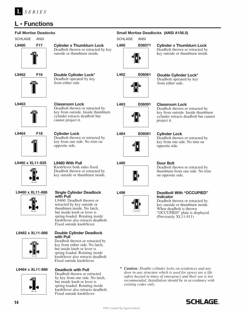
14
S E R I E SL
L • Functions
* Caution: Double cylinder locks on residences and anydoor in any structure which is used for egress are a lifesafety hazard in times of emergency and their use is notrecommended. Installation should be in accordance withexisting codes only.
SCHLAGE ANSI
Full Mortise Deadocks
SCHLAGE ANSI
Small Mortise Deadlocks (ANSI A156.5)
L9460 F17 Cylinder x Thumbturn LockDeadbolt thrown or retracted by keyoutside or thumbturn inside.
L460 E06071 Cylinder x Thumbturn LockDeadbolt thrown or retracted by key outside or thumbturn inside.
L462 E06061 Double Cylinder Lock*Deadbolt operated by key from either side.
L463 E06091 Classroom LockDeadbolt thrown or retracted by key from outside. Inside thumbturncylinder retracts deadbolt but cannotproject it.
L464 E06081 Cylinder LockDeadbolt thrown or retracted by key from one side. No trim on opposite side.
L480 Door BoltDeadbolt thrown or retracted bythumbturn from one side. No trim on opposite side.
OCCUPIED
L496 Deadbolt With “OCCUPIED”IndicatorDeadbolt thrown or retracted by key outside or thumbturn inside.When deadbolt is thrown “OCCUPIED” plate is displayed.(Previously XL11-911)
L9462 F16 Double Cylinder Lock*Deadbolt operated by key from either side.
L9463 Classroom LockDeadbolt thrown or retracted by key from outside. Inside thumbturncylinder retracts deadbolt but cannot project it.
L9464 F18 Cylinder LockDeadbolt thrown or retracted by key from one side. No trim onopposite side.
Deadlock with PullDeadbolt thrown or retracted by key from one side. No latch,but inside knob or lever is spring-loaded. Rotating insideknob/lever also retracts deadbolt.Fixed outside knob/lever.
Double Cylinder Deadlockwith PullDeadbolt thrown or retracted by key from either side. No latch,but inside knob or lever is spring-loaded. Rotating insideknob/lever also retracts deadbolt.Fixed outside knob/lever.
L9460 x XL11-635 L9460 With PullKnob/lever both sides fixed.Deadbolt thrown or retracted by key outside or thumbturn inside.
L9460 x XL11-886
L9462 x XL11-886
L9464 x XL11-886
Single Cylinder Deadlockwith PullL9460: Deadbolt thrown or retracted by key outside or thumbturn inside. No latch,but inside knob or lever is spring-loaded. Rotating insideknob/lever also retracts deadbolt.Fixed outside knob/lever.
PDF created by Specworks®
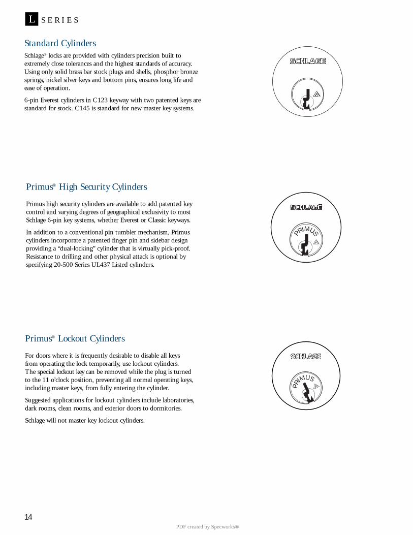
14
S E R I E SL
PRIMUS
Standard CylindersSchlage® locks are provided with cylinders precision built to extremely close tolerances and the highest standards of accuracy.Using only solid brass bar stock plugs and shells, phosphor bronzesprings, nickel silver keys and bottom pins, ensures long life and ease of operation.
6-pin Everest cylinders in C123 keyway with two patented keys arestandard for stock. C145 is standard for new master key systems.
Primus® High Security Cylinders
Primus high security cylinders are available to add patented key control and varying degrees of geographical exclusivity to mostSchlage 6-pin key systems, whether Everest or Classic keyways.
In addition to a conventional pin tumbler mechanism, Primuscylinders incorporate a patented finger pin and sidebar design providing a “dual-locking” cylinder that is virtually pick-proof.Resistance to drilling and other physical attack is optional byspecifying 20-500 Series UL437 Listed cylinders.
Primus® Lockout Cylinders
For doors where it is frequently desirable to disable all keys from operating the lock temporarily, use lockout cylinders. The special lockout key can be removed while the plug is turned to the 11 o’clock position, preventing all normal operating keys, including master keys, from fully entering the cylinder.
Suggested applications for lockout cylinders include laboratories,dark rooms, clean rooms, and exterior doors to dormitories.
Schlage will not master key lockout cylinders.
PR
IMUS
PDF created by Specworks®
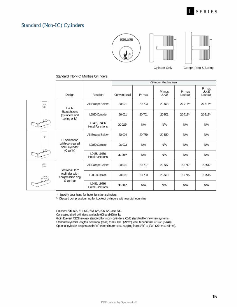
PrimusPrimus Primus UL437
Design Function Conventional Primus UL437 Lockout Lockout
All Except Below 30-021 20-793 20-593 20-717** 20-517**
L9060 Outside 26-021 20-701 20-501 20-715** 20-515**
L9485, L9486 30-022* N/A N/A N/A N/AHotel Functions
All Except Below 30-004 20-789 20-589 N/A N/A
L9060 Outside 26-023 N/A N/A N/A N/A
L9485, L9486 30-005* N/A N/A N/A N/AHotel Functions
All Except Below 30-001 20-787 20-587 20-717 20-517
L9060 Outside 20-001 20-700 20-500 20-715 20-515
L9485, L9486 30-002* N/A N/A N/A N/AHotel Functions
15
S E R I E SL
Standard (Non-IC) Mortise Cylinders
Cylinder Mechanism
* Specify door hand for hotel function cylinders.** Discard compression ring for Lockout cylinders with escutcheon trim.
Cylinder Only Compr. Ring & Spring
Finishes: 605, 606, 611, 612, 613, 625, 626, 629, and 630. Concealed shell cylinders available 606 and 626 only.6-pin Everest C123 keyway standard for stock cylinders. C145 standard for new key systems.Standard cylinder lengths: sectional (rose) trim = 11/8˝ (29mm), escutcheon trim = 11/4” (32mm).Optional cylinder lengths are in 1/8˝ (4mm) increments ranging from 11/8˝ to 13/4” (29mm to 44mm).
Standard (Non-IC) Cylinders
L & NEscutcheons
(cylinders andspring only)
L Escutcheonwith concealedshell cylinder
(C suffix)
Sectional Trim(cylinder with
compression ring& spring)
PDF created by Specworks®
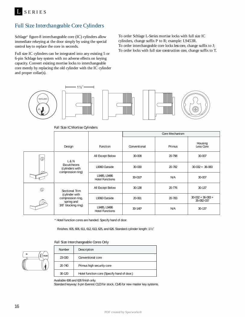
16
S E R I E SL
To order Schlage L-Series mortise locks with full size IC cylinders, change suffix P to R; example: L9453R.To order interchangeable core locks less core, change suffix to J;To order locks with full size construction core, change suffix to T.
Full Size Interchangeable Core Cylinders
Schlage® figure-8 interchangeable core (IC) cylinders allowimmediate rekeying at the door simply by using the specialcontrol key to replace the core in seconds.
Full size IC cylinders can be integrated into any existing 5 or6-pin Schlage key system with no adverse effects on keyingcapacity. Convert existing mortise locks to interchangeablecore merely by replacing the old cylinder with the IC cylinderand proper collar(s).
* Hotel function cores are handed. Specify hand of door.
Finishes: 605, 606, 611, 612, 613, 625, and 626. Standard cylinder length: 11 /2˝
HousingDesign Function Conventional Primus Less Core
All Except Below 30-008 20-798 30-007
L9060 Outside 30-030 20-782 30-032 + 36-083
L9485, L9486 30-010* N/A 30-007Hotel Functions
All Except Below 30-138 20-776 30-137
L9060 Outside 20-061 20-783 30-032 + 36-083 +35-082-037
L9485, L9486 30-140* N/A 30-137Hotel Functions
Core Mechanism
L & NEscutcheons
(cylinders withcompression ring)
Sectional Trim(cylinder with
compression ring,spring and
3/8˝ blocking ring)
Full Size Interchangeable Cores Only
Available 606 and 626 finish only.Standard keyway: 6-pin Everest C123 for stock, C145 for new master key systems.
Number Description
23-030 Conventional core
20-740 Primus high security core
30-120 Hotel function core (Specify hand of door.)
Full Size IC Mortise Cylinders
PDF created by Specworks®
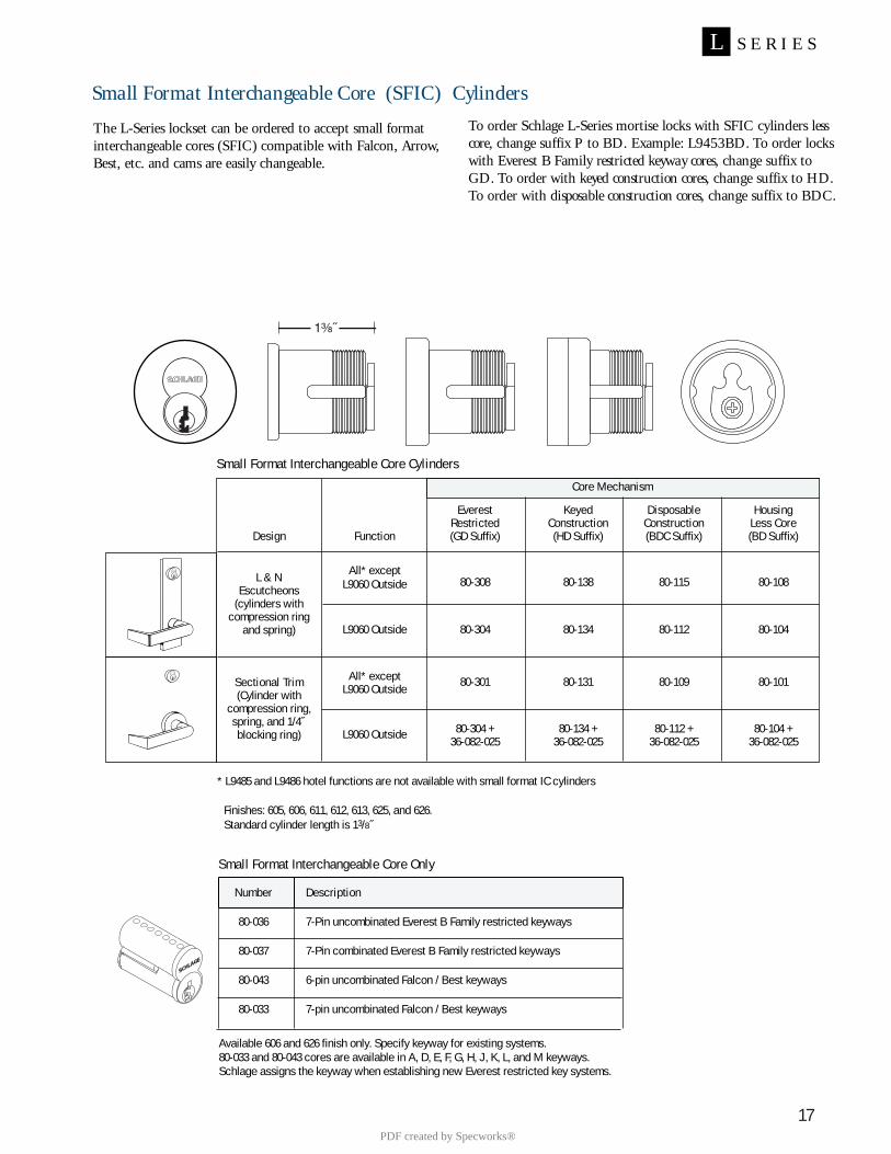
17
S E R I E SL
To order Schlage L-Series mortise locks with SFIC cylinders lesscore, change suffix P to BD. Example: L9453BD. To order lockswith Everest B Family restricted keyway cores, change suffix toGD. To order with keyed construction cores, change suffix to HD.To order with disposable construction cores, change suffix to BDC.
Small Format Interchangeable Core (SFIC) Cylinders
Number Description
80-036 7-Pin uncombinated Everest B Family restricted keyways
80-037 7-Pin combinated Everest B Family restricted keyways
80-043 6-pin uncombinated Falcon / Best keyways
80-033 7-pin uncombinated Falcon / Best keyways
Small Format Interchangeable Core Only
Available 606 and 626 finish only. Specify keyway for existing systems.80-033 and 80-043 cores are available in A, D, E, F, G, H, J, K, L, and M keyways.Schlage assigns the keyway when establishing new Everest restricted key systems.
The L-Series lockset can be ordered to accept small formatinterchangeable cores (SFIC) compatible with Falcon, Arrow,Best, etc. and cams are easily changeable.
* L9485 and L9486 hotel functions are not available with small format IC cylinders
Finishes: 605, 606, 611, 612, 613, 625, and 626.Standard cylinder length is 13/8˝
Everest Keyed Disposable HousingRestricted Construction Construction Less Core
Design Function (GD Suffix) (HD Suffix) (BDC Suffix) (BD Suffix)
All* exceptL9060 Outside 80-308 80-138 80-115 80-108
L9060 Outside 80-304 80-134 80-112 80-104
All* except 80-301 80-131 80-109 80-101L9060 Outside
L9060 Outside 80-304 + 80-134 + 80-112 + 80-104 +36-082-025 36-082-025 36-082-025 36-082-025
Small Format Interchangeable Core Cylinders
Core Mechanism
L & NEscutcheons
(cylinders withcompression ring
and spring)
Sectional Trim(Cylinder with
compression ring,spring, and 1/4˝blocking ring)
PDF created by Specworks®
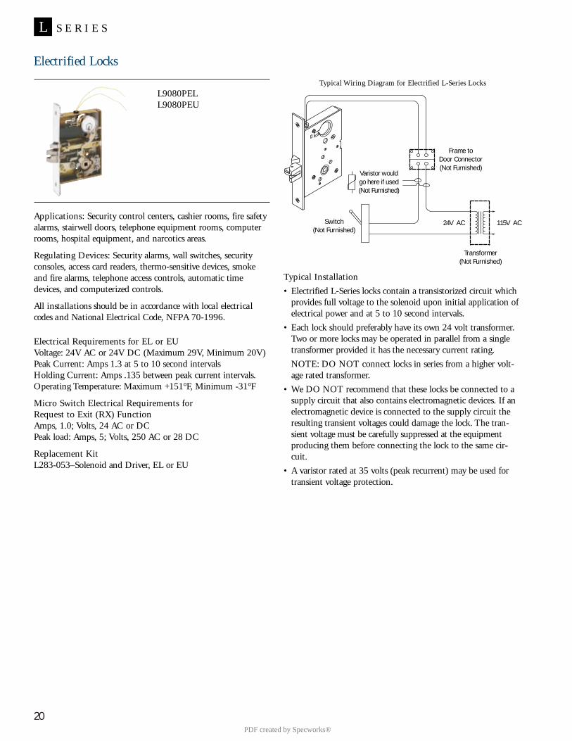
20
S E R I E SL
Electrified Locks
L9080PELL9080PEU
Applications: Security control centers, cashier rooms, fire safetyalarms, stairwell doors, telephone equipment rooms, computerrooms, hospital equipment, and narcotics areas.
Regulating Devices: Security alarms, wall switches, securityconsoles, access card readers, thermo-sensitive devices, smokeand fire alarms, telephone access controls, automatic timedevices, and computerized controls.
All installations should be in accordance with local electricalcodes and National Electrical Code, NFPA 70-1996.
Electrical Requirements for EL or EUVoltage: 24V AC or 24V DC (Maximum 29V, Minimum 20V)Peak Current: Amps 1.3 at 5 to 10 second intervalsHolding Current: Amps .135 between peak current intervals.Operating Temperature: Maximum +151°F, Minimum -31°F
Micro Switch Electrical Requirements forRequest to Exit (RX) FunctionAmps, 1.0; Volts, 24 AC or DCPeak load: Amps, 5; Volts, 250 AC or 28 DC
Replacement KitL283-053–Solenoid and Driver, EL or EU
Typical Installation• Electrified L-Series locks contain a transistorized circuit which
provides full voltage to the solenoid upon initial application ofelectrical power and at 5 to 10 second intervals.
• Each lock should preferably have its own 24 volt transformer.Two or more locks may be operated in parallel from a singletransformer provided it has the necessary current rating. NOTE: DO NOT connect locks in series from a higher volt-age rated transformer.
• We DO NOT recommend that these locks be connected to asupply circuit that also contains electromagnetic devices. If anelectromagnetic device is connected to the supply circuit theresulting transient voltages could damage the lock. The tran-sient voltage must be carefully suppressed at the equipmentproducing them before connecting the lock to the same cir-cuit.
• A varistor rated at 35 volts (peak recurrent) may be used fortransient voltage protection.
Typical Wiring Diagram for Electrified L-Series Locks
Frame to Door Connector (Not Furnished)
Varistor wouldgo here if used (Not Furnished)
Switch(Not Furnished)
Transformer(Not Furnished)
24V AC 115V AC
PDF created by Specworks®
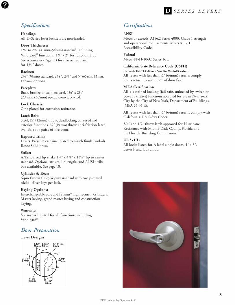
3
Specifications
Handing:All D-Series lever locksets are non-handed.
Door Thickness:1⅝˝ to 2⅛˝ (41mm–54mm) standard includingVandlgard® functions. 1¾˝ - 2˝ for function D85.See accessories (Page 11) for spacers required for 1³⁄ 8˝ doors.
Backset:2³⁄₄˝ (70mm) standard. 2³⁄ 8˝, 3¾˝ and 5˝ (60mm, 95mm,127mm) optional.
Faceplate:Brass, bronze or stainless steel. 1⅛˝ x 2¼˝(29 mm x 57mm) square corner, beveled.
Lock Chassis:Zinc plated for corrosion resistance.
Latch Bolt:Steel, ½˝ (12mm) throw, deadlocking on keyed andexterior functions. ³⁄₄˝ (19mm) throw anti-friction latchavailable for pairs of fire doors.
Exposed Trim:Levers: Pressure cast zinc, plated to match finish symbols.Roses: Solid brass.
Strike:ANSI curved lip strike 1¼˝ x 4⅞˝ x 1³⁄₁₆˝ lip to centerstandard. Optional strikes, lip lengths and ANSI strikebox available. See page 10.
Cylinder & Keys:6-pin Everest C123 keyway standard with two patentednickel silver keys per lock.
Keying Options:Interchangeable core and Primus® high security cylinders.Master keying, grand master keying and constructionkeying.
Warranty:Seven-year limited for all functions includingVandlgard®.
Certifications
ANSIMeets or exceeds A156.2 Series 4000, Grade 1 strengthand operational requirements. Meets A117.1Accessibility Code.
FederalMeets FF-H-106C Series 161.
California State Reference Code (CSFH)(Formerly Title 19, California State Fire Marshal Standard)
All levers with less than ½˝ (64mm) returns comply;levers return to within ½˝ of door face.
M E A CertificationAll electrified locking (fail-safe, unlocked by switch orpower failures) functions accepted for use in New YorkCity by the City of New York, Department of Buildings(MEA 24-04-E).
All levers with less than ½˝ (64mm) returns comply withCalifornia Fire Safety Codes.
3/4˝ and 1/2˝ throw latch approved for HurricaneResistance with Miami-Dade County, Florida and the Florida Building Commission.
UL / cUL:All locks listed for A label single doors, 4´ x 8´.Letter F and UL symbol
Door Preparation
2-1/4"57mm
2-3/4"70mm
5/16" dia.8mm
1" dia25mm 2-1/8"
54mm
1-1/8"29mm
2-3/4"70mm
Lever Designs
PDF created by Specworks®

4
Lever Designs & Finishes
ATHENSSymbol: ATH (L-Series 07)Material: Pressure castzinc lever; wrought brass roseFinishes:605, 606, 612,613, 619, 625, 626
RHODESSymbol: RHO (L-Series 06)Material: Pressure castzinc lever; wrought brass roseFinishes:605, 606, 612,613, 619, 625, 626
SPARTA Symbol: SPA (L-Series 17)Material: Pressure castzinc lever; wrought brass roseFinishes:605, 606, 612, 613, 619, 625, 626
Lever Designs & Finishes
606
612
626
Finishes605 Bright Brass606 Satin Brass612 Satin Bronze613 Oil Rubbed Bronze619 Satin Nickel625 Bright Chromium Plated626 Satin Chromium Plated
Keyed functions available with Smal l Format Interchangeable Core options.
TACTILE WARNING(KNURLING)Change symbol designation as follows:8AT for Athens8RO for Rhodes8SP for Sparta8TR for Tubular*�
Only outside lever is knurled unless otherwise specified.
Not available with Omega trim
� Extended Factory Lead Time
OMEGASymbol: OME (L-Series Omega)Material: Pressure castzinc lever; wrought brass roseFinishes:605, 606, 612, 613, 619, 625, 626
605Bright Brass
606Satin Brass
612Satin Bronze
613Oil Rubbed
Bronze
619Satin Nickel
625Bright Chromium
Plated
626Satin Chromium
Plated
TUBULAR (L-Series 03)Symbol: TLRMaterial: Pressure castzinc lever; wrought brass roseFinishes:605, 606, 612,613, 619, 625, 626
626
619
Keyed functions available with Full Size Interchangeable Core options.
*Only available with Tubular lever.
*
PDF created by Specworks®
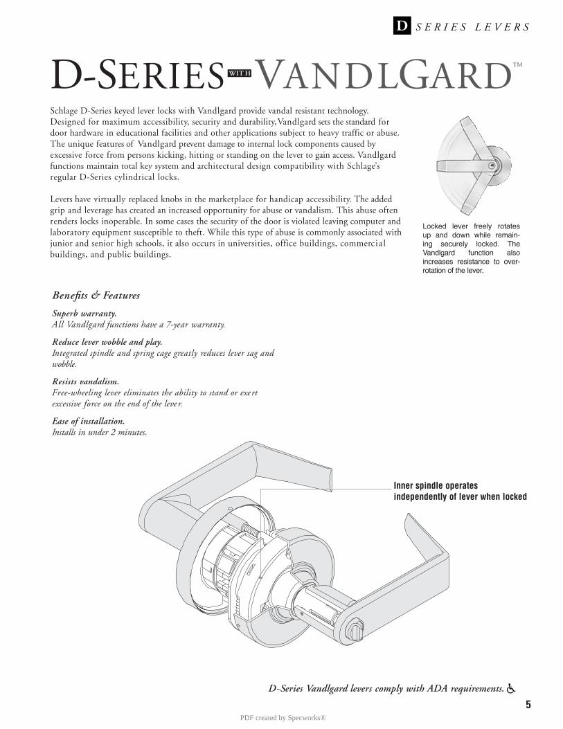
5D-Series Vandlgard levers comply with ADA requirements.
Schlage D-Series keyed lever locks with Vandlgard provide vandal resistant technology.Designed for maximum accessibility, security and durability, Vandlgard sets the standard fordoor hardware in educational facilities and other applications subject to heavy traffic or abuse.The unique features of Vandlgard prevent damage to internal lock components caused byexcessive force from persons kicking, hitting or standing on the lever to gain access. Vandlgardfunctions maintain total key system and architectural design compatibility with Schlage’sregular D-Series cylindrical locks.
Levers have virtually replaced knobs in the marketplace for handicap accessibility. The addedgrip and leverage has created an increased opportunity for abuse or vandalism. This abuse oftenrenders locks inoperable. In some cases the security of the door is violated leaving computer andlaboratory equipment susceptible to theft. While this type of abuse is commonly associated withjunior and senior high schools, it also occurs in universities, office buildings, commercia lbuildings, and public buildings.
D-SERIES VANDLGARD™WIT H
Inner spindle operatesindependently of lever when locked
Locked lever freely rotates up and down while remain-ing securely locked. TheVandlgard function alsoincreases resistance to over-rotation of the lever.
Benefits & Features
Superb warranty. All Vandlgard functions have a 7-year warranty.
Reduce lever wobble and play.Integrated spindle and spring cage greatly reduces lever sag andwobble.
Resists vandalism.Free-wheeling lever eliminates the ability to stand or exe rtexcessive force on the end of the leve r.
Ease of installation.Installs in under 2 minutes.
PDF created by Specworks®
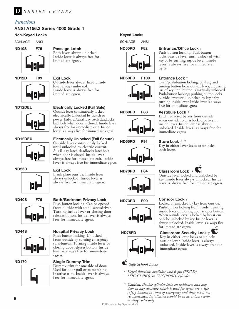
6
FunctionsANSI A156.2 Series 4000 Grade 1
SCHLAGE ANSI
Non-Keyed Locks
ND10S F75 Passage LatchBoth levers always unlocked.Inside lever is always free forimmediate egress.
ND50PD F82 Entrance/Office Lock †Push-button locking. Push-buttonlocks outside lever until unlocked withkey or by turning inside lever. Insidelever is always free for immediateegress.
ND53PD F109 Entrance Lock †Turn/push-button locking; pushing andturning button locks outside lever, requiringuse of key until button is manually unlocked.Push-button locking; pushing button locksoutside lever until unlocked by key or byturning inside lever. Inside lever is alwaysf ree for immediate egress.
ND60PD F88 Vestibule Lock †Latch retracted by key from outsidewhen outside lever is locked by key ininside lever. Inside lever is alwaysunlocked. Inside lever is always free forimmediate egress.
ND66PD F91 Store Lock † *Key in either lever locks or unlocksboth levers.
ND70PD F84 Classroom Lock †Outside lever locked and unlocked bykey. Inside lever always unlocked. Insidelever is always free for immediate egress.
ND73PD F90 Corridor Lock †Locked or unlocked by key from outside.Push-button locking from inside. Turninginside lever or closing door releases button.When outside lever is locked by key it canonly be unlocked by key. Inside lever isalways unlocked. Inside lever is always freefor immediate egress.
ND12D F89 Exit LockOutside lever always fixed. Insidelever always unlocked.Inside lever is always free forimmediate egress.
ND12DEL Electrically Locked (Fail Safe)Outside lever continuously lockedelectrically. Unlocked by switch orpower failure. Auxiliary latch deadlockslatchbolt when door is closed. Inside leveralways free for immediate exit. Insidelever is always free for immediate egress.
SCHLAGE ANSI
Keyed Locks
† Keyed functions available with 6-pin (PD/LD), SFIC(GD/BD), or FSIC(RD/JD) cylinder.
* Caution: Double cylinder locks on residences and anydoor in any structure which is used for egress are a lifesafety hazard in times of emergency and their use is notrecommended. Installation should be in accordance withexisting codes only.
Safe School Locks
ND12DEU Electrically Unlocked (Fail Secure)Outside lever continuously lockeduntil unlocked by electric current.Auxi l iary latch deadlocks latchboltwhen door is closed. Inside leveralways free for immediate exit. Insidelever is always free for immediate egress.
ND25D Exit LockBlank plate outside. Inside leveralways unlocked. Inside lever isalways free for immediate egress.
ND40S F76 Bath/Bedroom Privacy LockPush-button locking. Can be openedf rom outside with small screwdriver.Turning inside lever or closing doorreleases button. Inside lever is alwaysf ree for immediate egress.
ND44S Hospital Privacy LockPush-button locking. Unlockedf rom outside by turning emergencyturn-button. Turning inside lever orclosing door releases button. Insidelever is always free for immediateegress.
ND170 Single Dummy TrimDummy trim for one side of door.Used for door pull or as matchinginactive trim. Inside lever is alwaysf ree for immediate egress.
ND75PD Classroom Security Lock †Key in either lever locks or unlocksoutside lever. Inside lever is alwaysunlocked. Inside lever is always free forimmediate egress.
PDF created by Specworks®
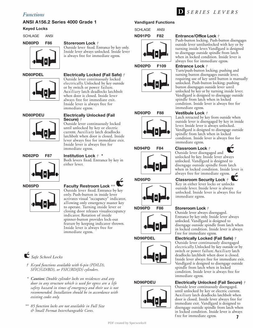
7
FunctionsANSI A156.2 Series 4000 Grade 1
† Keyed functions available with 6-pin (PD/LD), SFIC(GD/BD), or FSIC(RD/JD) cylinders.
* Caution: Double cylinder locks on residences and anydoor in any structure which is used for egress are a lifesafety hazard in times of emergency and their use is notrecommended. Installation should be in accordance withexisting codes only.
** 85 function locks are not available in Full Size & Small Format Interchangeable Cores.
ND80PD F86 Storeroom Lock †Outside lever fixed. Entrance by key only.Inside lever always unlocked. Inside leveris always free for immediate egress.
ND80PDEL Electrically Locked (Fail Safe) †Outside lever continuously lockedelectrically. Unlocked by key outsideor by switch or power failure.Auxi l iary latch deadlocks latchboltwhen door is closed. Inside leveralways free for immediate exit.Inside lever is always free forimmediate egress.
ND80PDEU Electrically Unlocked (FailSecure) †Outside lever continuously lockeduntil unlocked by key or electriccurrent. Auxi l iary latch deadlockslatchbolt when door is closed. Insidelever always free for immediate exit.Inside lever is always free forimmediate egress.
ND82PD F87 Institution Lock † *Both levers fixed. Entrance by key ineither lever.
SCHLAGE ANSI
Keyed Locks
ND91PD F82 Entrance/Office Lock †Push-button locking. Push-button disengagesoutside lever untilunlocked with key or byturning inside lever. Vandlgard is designedto disengage outside spindle from latchwhen in locked condition. Inside lever isalways free for immediate egress.
ND92PD F109 Entrance Lock †Turn/push-button locking; pushing andturning button disengages outside lever,requiring use of key until button is manuallyunlocked. Push-button locking; pushingbutton disengages outside lever untilunlocked by key or by turning inside lever.Vandlgard is designed to disengage outsidespindle from latch when in lockedcondition. Inside lever is always free forimmediate egress.
ND93PD F88 Vestibule Lock †Latch retracted by key from outside whenoutside lever is disengaged by key in insidelever. Inside lever is always unlocked.Vandlgard is designed to disengage outsidespindle from latch when in lockedcondition. Inside lever is always free forimmediate egress.
ND94PD F84 Classroom Lock †Outside lever disengaged andunlocked by key. Inside lever alwaysunlocked. Vandlgard is designed todisengage outside spindle from latchwhen in locked condition. Inside lever isalways free for immediate egress.
ND96PD F86 Storeroom Lock †Outside lever always disengaged.Entrance by key only. Inside lever alwaysunlocked. Vandlgard is designed todisengage outside spindle from latch whenin locked condition. Inside lever is alwaysf ree for immediate egress.
SCHLAGE ANSI
Vandlgard Functions
ND96PDEL Electrically Locked (Fail Safe) †Outside lever continuously disengagedelectrically. Unlocked by key outside or byswitch or power failure. Auxiliary latchdeadlocks latchbolt when door is closed.Inside lever always free for immediate exit.Vandlgard is designed to disengage outsidespindle from latch when in lockedcondition. Inside lever is always free forimmediate egress.
ND96PDEU Electrically Unlocked (Fail Secure) †Outside lever continuously disengaged.until unlocked by key or electric current.Auxiliary latch deadlocks latchbolt whendoor is closed. Inside lever always free forimmediate exit. Vandlgard is designed todisengage outside spindle from latch whenin locked condition. Inside lever is alwaysf ree for immediate egress.
ND85PD Faculty Restroom Lock **Outside lever fixed. Entrance by keyonly. Push-button in inside lever activates visual “occupancy” indicator,a l lowing only emergency master keyto operate. Turning inside lever orclosing door releases visualoccupancyindicator. Rotation of inside spinner-button provides lock-outfeature by keeping indicator thrown.Inside lever is always free forimmediate egress.
ND95PD Classroom Security Lock †Key in either lever locks or unlocksoutside lever. Inside lever is alwaysunlocked. Inside lever is always free forimmediate egress.
Safe School Locks
PDF created by Specworks®
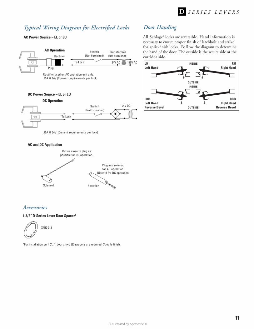
Door Handing
All Schlage® locks are reversible. Hand information isnecessary to ensure proper finish of latchbolt and strike for split-finish locks. Fo l low the diagram to determine the hand of the door. The outside is the secure side or thecorridor side.
LHLeft Hand
INSIDE
OUTSIDE
OUTSIDE
INSIDE
LRBLeft HandReverse Bevel
RHRight Hand
RRBRight Hand
Reverse Bevel
11
DC Power Source – EL or EU
Switch(Not Furnished)
Transformer(Not Furnished)
Typical Wiring Diagram for Electrified Locks
AC Operation
Rectifier
To Lock
Plug
Rectifier used on AC operation unit only..35A @ 24V (Current requirements per lock)
24V AC 115V AC
Switch(Not Furnished)
DC Operation
To Lock
.15A @ 24V (Current requirements per lock)
AC and DC Application
Solenoid Rectifier
Cut as close to plug aspossible for DC operation.
Plug into solenoid for AC operation.
Discard for DC operation.
24V DC
AC Power Source – EL or EU
1-3/8˝ D-Series Lever Door Spacer*
Accessories
XN12-012
*For installation on 1 C\,” doors, two (2) spacers are required. Specify finish.
PDF created by Specworks®

Certifications
ANSI:BC100 and B250-Series meet or exceed A156.5 Grade 2strength and operational requirements.
B600/700/800-Series meets or exceeds A156.5 Grade 1strength and operational requirements.
UL / cUL:B600/700/800-Series locks are UL10B listed auxiliarylocks for A label single doors, 4´ x 8´.
UL10B Listing optional for BC100-Series as auxiliarylocks. Letter F and UL symbol on latch front indicatelisting.
UL437 Listed locking cylinder optional: Specify Primus20-500 Series cylinder for BC100 and B250-Series Grade2 products, or specify B800-Series Grade 1 products.
3
S E R I E SB
BC160 Deadlock 605
B250 IC Deadlatch 626
B660 Deadlock 625
Specifications
Handing:B250-Series deadlatches are reversible. All other B-Serieslocksets are non-handed.
Door Thickness:BC100-Series, 5-pin: 1⅜˝ to 1¾˝ thick (35mm to 44mm)standard. Available to 2¼˝ (57mm), assembled to order.
B250-Series, 5-pin: 1⅛˝ to 1¾˝ (35mm to 44mm) standard.Available to 2¼˝ (57mm), assembled to order.
B600/700/800-Series: 1¾˝ to 2" (44mm to 51mm) standard.Available for 1⅜˝ (35mm) and doors up to 2½˝ (63mm),assembled to order. Door ranges may vary by function.
Backset:BC100-Series: Adjustable for 2⅜˝ (60mm) or 2¾˝ (70mm)standard.
B250-Series: 2⅜˝ (60mm) standard. 2¾˝ (70mm) optional.
B600/700/800-Series: 2¾˝ (70mm) standard, 2⅜˝ (60mm),3¾˝ (95mm), 5" (127mm) optional.
Front:Brass, bronze or stainless steel. 1⅛˝ x 2¼˝ (29 mm x57mm) square corner, beveled. See page 12 for options.
Dead Bolt:1” (25 mm) throw with saw-resistant hardened steel insert.
Latch Bolt:Brass, ⁹⁄₁₆˝ (14mm) throw, deadlocking on keyed and exte-rior functions.
Exposed Trim:Wrought brass, bronze or stainless steel.Thumbturn: Pressure cast zinc, plated to match finishsymbols.
Strike:1¼˝ x 2³⁄₄˝ (32mm x 70mm) with steel reinforcer and two3” screws to resist kick-in attacks standard.Optional strikes, lip lengths and ANSI strike box avail-able. See page 13.
Cylinder & Keys:Commercial: 6-pin patented Everest C123 keyway stan-dard with two nickel silver keys per lock.Residential: 6-pin C keyway, keyed 5-pin.
Keying Options:Interchangeable core and Primus® high security cylinders.Master keying, grand master keying and construction key-ing.
Warranty:Commercial: Three-year limited.Residential: Full mechanical lifetime.
PDF created by Specworks®
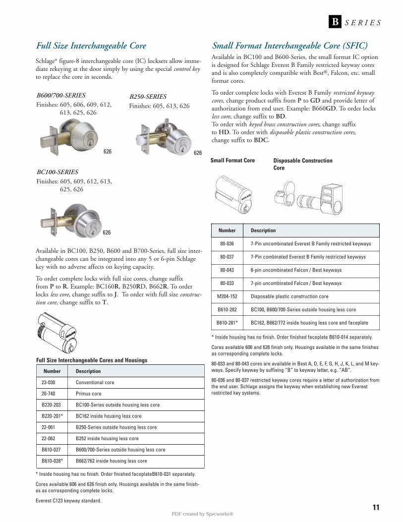
11
S E R I E SB
* Inside housing has no finish. Order finished faceplateB610-031 separately.
Cores available 606 and 626 finish only. Housings available in the same finish-es as corresponding complete locks.
Everest C123 keyway standard.
Full Size Interchangeable Core
Schlage® figure-8 interchangeable core (IC) locksets allow imme-diate rekeying at the door simply by using the special control keyto replace the core in seconds.
Available in BC100, B250, B600 and B700-Series, full size inter-changeable cores can be integrated into any 5 or 6-pin Schlagekey with no adverse affects on keying capacity.
To order complete locks with full size cores, change suffix from P to R. Example: BC160R, B250RD, B662R. To orderlocks less core, change suffix to J. To order with full size construc-tion core, change suffix to T.
626
B600/700-SERIESFinishes: 605, 606, 609, 612,
613, 625, 626
626
B250-SERIESFinishes: 605, 613, 626
626
BC100-SERIESFinishes: 605, 609, 612, 613,
625, 626
Number Description
23-030 Conventional core
20-740 Primus core
B220-203 BC100-Series outside housing less core
B220-201* BC162 inside housing less core
22-061 B250-Series outside housing less core
22-062 B252 inside housing less core
B610-027 B600/700-Series outside housing less core
B610-028* B662/762 inside housing less core
Full Size Interchangeable Cores and Housings
Small Format Interchangeable Core (SFIC)Available in BC100 and B600-Series, the small format IC optionis designed for Schlage Everest B Family restricted keyway coresand is also completely compatible with Best®, Falcon, etc. smallformat cores.
To order complete locks with Everest B Family restricted keywaycores, change product suffix from P to GD and provide letter ofauthorization from end user. Example: B660GD. To order locksless core, change suffix to BD.To order with keyed brass construction cores, change suffix to HD. To order with disposable plastic construction cores,change suffix to BDC.
Number Description
80-036 7-Pin uncombinated Everest B Family restricted keyways
80-037 7-Pin combinated Everest B Family restricted keyways
80-043 6-pin uncombinated Falcon / Best keyways
80-033 7-pin uncombinated Falcon / Best keyways
M204-152 Disposable plastic construction core
B610-282 BC100, B600/700-Series outside housing less core
B610-281* BC162, B662/772 inside housing less core and faceplate
Small Format Core
* Inside housing has no finish. Order finished faceplate B610-014 separately.
Cores available 606 and 626 finish only. Housings available in the same finishesas corresponding complete locks.
80-033 and 80-043 cores are available in Best A, D, E, F, G, H, J, K, L, and M key-ways. Specify keyway by suffixing “B” to keyway letter, e.g. “AB”.
80-036 and 80-037 restricted keyway cores require a letter of authorization fromthe end user. Schlage assigns the keyway when establishing new Everestrestricted key systems.
Disposable ConstructionCore
PDF created by Specworks®
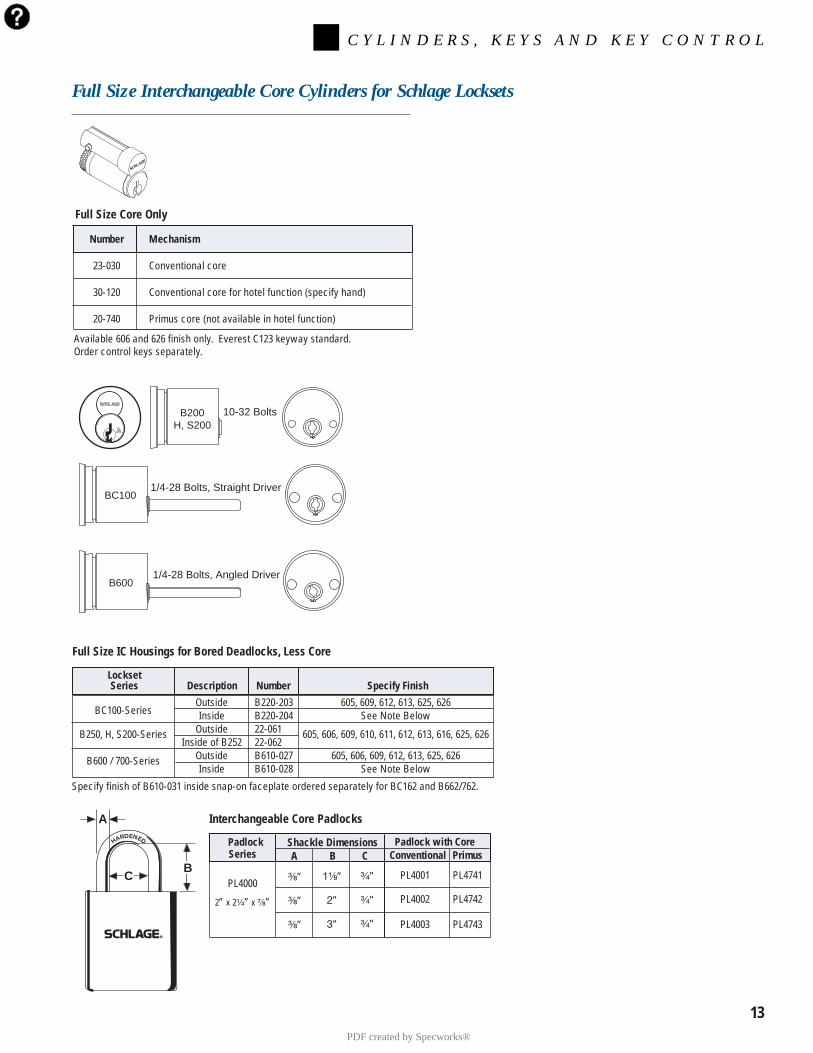
Full Size Interchangeable Core Cylinders for Schlage Locksets
BC100-SeriesOutside B220-203 605, 609, 612, 613, 625, 626Inside B220-204 See Note Below
B250, H, S200-Series Outside 22-061 605, 606, 609, 610, 611, 612, 613, 616, 625, 626Inside of B252 22-062
B600 / 700-Series Outside B610-027 605, 606, 609, 612, 613, 625, 626Inside B610-028 See Note Below
LocksetSeries Description Number Specify Finish
Specify finish of B610-031 inside snap-on faceplate ordered separately for BC162 and B662/762.
Full Size IC Housings for Bored Deadlocks, Less Core
Interchangeable Core Padlocks
Number Mechanism
23-030 Conventional core
30-120 Conventional core for hotel function (specify hand)
20-740 Primus core (not available in hotel function)
Full Size Core Only
Available 606 and 626 finish only. Everest C123 keyway standard.Order control keys separately.
B600
BC100
B200H, S200
1/4-28 Bolts, Angled Driver
1/4-28 Bolts, Straight Driver
10-32 Bolts
13
Padlock with CoreConventional Primus
PL4001 PL4741
PL4002 PL4742
PL4003 PL4743
PadlockSeries
PL4000
2” x 2¹⁄₄” x ⁷⁄₈”
³⁄₈”
³⁄₈”
³⁄₈”
1¹⁄₈”
2”
3”
³⁄₄”
³⁄₄”
³⁄₄”
Shackle DimensionsA B C
HARDENED
CB
A
C Y L I N D E R S , K E Y S A N D K E Y C O N T R O L
PDF created by Specworks®

15
Number Core Mechanism
20-057 Conventional core
20-757 Primus core
20-079 Housing only, less core
Interchangeable Core Rim Cylinders for Exit Devices
Available 605, 606, 612, 613, 625 and 626 finish.Everest C123 keyway standard.
Full Size Interchangeable Core Cylinders for Exit Devices, Aluminum Doors, etc.
Number Core Mechanism Collar
26-098 Conventional core Compression ring & spring
20-062 Conventional core 3/16˝ + 3/8˝ blocking rings
20-766 Primus core 3/16˝ + 3/8˝ blocking rings
20-060 Housing less core None
Cylinders for Adams Rite MS and 4700 SeriesLori 4500 Series and Corbin Russwin DL3000 Series
Number Core Mechanism Collar
20-091 Conventional core 3/16˝ + 3/8˝ blocking rings
20-722 Primus core 3/16˝ + 3/8˝ blocking rings
20-090 Housing less core None
Cylinders for Adams Rite 4070 Series Deadlocks
These cylinders include set screw pack B220-050 for Adams Rite locks.
K510-711Adams Rite
MS Cam
B520-378Adams Rite4070 Cam
Notes 1. Mortise cylinders available 605, 606, 612, 613, 625, and 626 finish. Cores furnished 606 and 626 only.2. To differentiate between Classic and Everest, specify keyway. Example: C or CP (Classic), C123 (Everest). Everest C123 keyway standard. 3. All cylinders are 11/2˝ long.4. Specify LKB if 0-bitted Primus cylinders are required less key blanks.
C Y L I N D E R S , K E Y S A N D K E Y C O N T R O L
PDF created by Specworks®
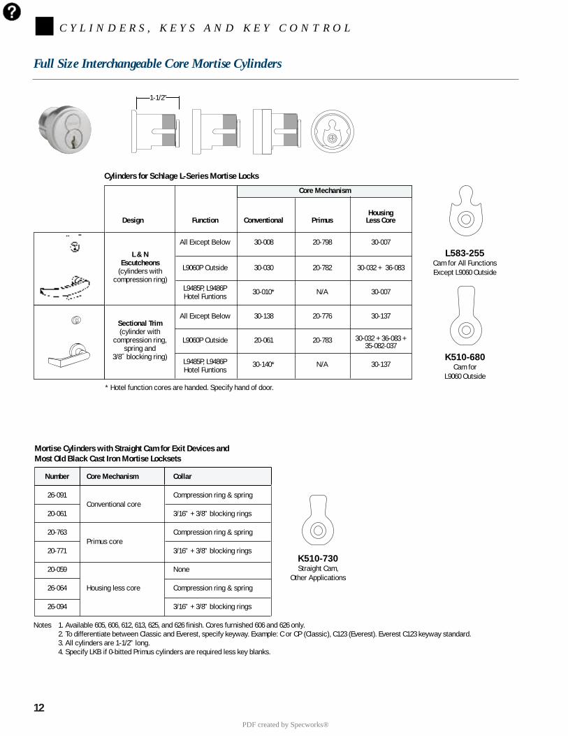
12
C Y L I N D E R S , K E Y S A N D K E Y C O N T R O L
Full Size Interchangeable Core Mortise Cylinders
K510-730Straight Cam,
Other Applications
L583-255Cam for All FunctionsExcept L9060 Outside
K510-680Cam for
L9060 Outside* Hotel function cores are handed. Specify hand of door.
HousingDesign Function Conventional Primus Less Core
All Except Below 30-008 20-798 30-007
L9060P Outside 30-030 20-782 30-032 + 36-083
L9485P, L9486P 30-010* N/A 30-007Hotel Funtions
All Except Below 30-138 20-776 30-137
L9060P Outside 20-061 20-783 30-032 + 36-083 +35-082-037
L9485P, L9486P 30-140* N/A 30-137Hotel Funtions
Core Mechanism
L & NEscutcheons
(cylinders withcompression ring)
Sectional Trim(cylinder with
compression ring,spring and
3/8˝ blocking ring)
Cylinders for Schlage L-Series Mortise Locks
Number Core Mechanism Collar
26-091Conventional core
Compression ring & spring
20-061 3/16” + 3/8” blocking rings
20-763Primus core
Compression ring & spring
20-771 3/16” + 3/8” blocking rings
20-059 None
26-064 Housing less core Compression ring & spring
26-094 3/16” + 3/8” blocking rings
Mortise Cylinders with Straight Cam for Exit Devices andMost Old Black Cast Iron Mortise Locksets
1-1/2”
Notes 1. Available 605, 606, 612, 613, 625, and 626 finish. Cores furnished 606 and 626 only.2. To differentiate between Classic and Everest, specify keyway. Example: C or CP (Classic), C123 (Everest). Everest C123 keyway standard. 3. All cylinders are 1-1/2” long.4. Specify LKB if 0-bitted Primus cylinders are required less key blanks.
PDF created by Specworks®
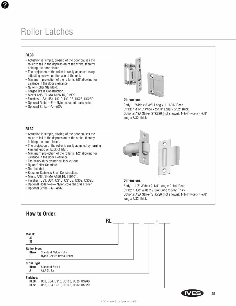
G1
Model:3032
Roller Type: Blank Standard Nylon RollerF Nylon Coated Brass Roller
Strike Type: Blank Standard StrikeA ASA Strike
Finishes: RL30 US3, US4, US10, US10B, US26, US26DRL32 US3, US4, US10, US10B, US32, US32D
Roller Latches
RL30• Actuation is simple, closing of the door causes the
roller to fall in the depression of the strike, thereby holding the door closed.
• The projection of the roller is easily adjusted using adjusting screws on the face of the unit.
• Maximum projection of the roller is 3/8" allowing for variance in the door clearance.
• Nylon Roller Standard.• Forged Brass Construction.• Meets ANSI/BHMA A156.16, E19091.• Finishes: US3, US4, US10, US10B, US26, US26D.• Optional Roller—F— Nylon covered brass roller.• Optional Strike—A—ASA
RL32• Actuation is simple, closing of the door causes the
roller to fall in the depression of the strike, thereby holding the door closed.
• The projection of the roller is easily adjusted by turning knurled knob on back of latch.
• Maximum projection of the roller is 1/2" allowing for variance in the door clearance.
• Fits heavy-duty cylindrical lock cutout.• Nylon Roller Standard.• Non-handed.• Brass or Stainless Steel Construction.• Meets ANSI/BHMA A156.16, E19101.• Finishes: US3, US4, US10, US10B, US32, US32D.• Optional Roller—F— Nylon covered brass roller.• Optional Strike—A—ASA.
How to Order:RL ____ ____ ____ - ____
Dimensions:
Body: 1" Wide x 3-3/8" Long x 1-11/16" DeepStrike: 1-11/16" Wide x 2-1/4" Long x 5/32" ThickOptional ASA Strike: STK726 (not shown): 1-1/4" wide x 4-7/8" long x 3/32" thick
Dimensions:
Body: 1-1/8" Wide x 2-1/4" Long x 2-1/4" DeepStrike: 1-1/8" Wide x 2-3/4" Long x 3/32" ThickOptional ASA Strike: STK726 (not shown): 1-1/4" wide x 4-7/8" long x 3/32" thick
PDF created by Specworks®

C5
How to Order8121-5 - ____ - ____
Finishes: US3, US10, US10B, US15, US15A, US26, US26D, US28
Mounting Type:Blank StandardF Concealed wood door w/push plate (special)K Back to back pulls. Furnished is Pairs (PR).
8121 Door Pull
Prod. Proj. Center to Center Overall LengthNo. “A” “B” “C”
8121-5 3-1/2" 5-3/4" 8-3/4"
Architectural Door Trim
8100 Series Door Pulls• Made from the finest architectural brass, stainless steel
and aluminum available.• Each pull is carefully machined, polished and inspected before
being individually wrapped and packaged.
• Door pulls are packed with standard type fasteners for 1-3/4"doors. For special mounting methods other than standard, see pages C11 - C13.
• For sizes and finishes not listed in this catalog, contact ourCustomer Service Department for availability.
8190 90° Offset Door PullProd. Proj. Center to Center Overall LengthNo. “A” “B” “C”
8190 3-1/4" 8" 9"8190 3-1/4" 10" 11"8190 3-1/4" 12" 13"8190 3-1/4" 18" 19"
Size:8 for 8"0 for 10"2 for 12"18 for 18"
FinishesUS3, US4, US10, US10B, US15, US15A, US26, US26D, US32, US32D
Mounting Type:Blank StandardL Surface Concealed Two-Anchor M Back-To-Back with Spanner Collar. Furnished in Pairs. (PR)M1 Single (SGL) Pull. Back-to-Back With
Spanner Collar. RH Thread.M2 Single (SGL) Pull. Back-to-Back With
Spanner Collar. LH Thread.N Back-to-Back Two-Anchor. Furnished in Pairs. (PR)N2 Single (SGL) Pull, Back-to-Back Two Anchor.O Decorative Blind Thru-Bolt
How to Order8190 - ___ - ___ - ___
PDF created by Specworks®
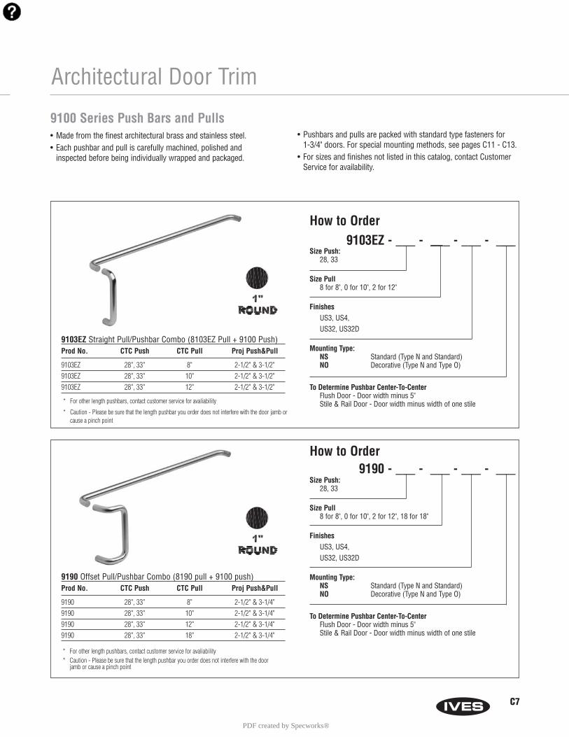
9190 Offset Pull/Pushbar Combo (8190 pull + 9100 push)Prod No. CTC Push CTC Pull Proj Push&Pull
9190 28", 33" 8" 2-1/2" & 3-1/4"9190 28", 33" 10" 2-1/2" & 3-1/4"9190 28", 33" 12" 2-1/2" & 3-1/4"9190 28", 33" 18" 2-1/2" & 3-1/4"
Size Push:28, 33
Size Pull8 for 8", 0 for 10", 2 for 12", 18 for 18"
FinishesUS3, US4,US32, US32D
Mounting Type:NS Standard (Type N and Standard)NO Decorative (Type N and Type O)
To Determine Pushbar Center-To-CenterFlush Door - Door width minus 5"Stile & Rail Door - Door width minus width of one stile
* For other length pushbars, contact customer service for avaliability* Caution - Please be sure that the length pushbar you order does not interfere with the door
jamb or cause a pinch point
Architectural Door Trim
9103EZ Straight Pull/Pushbar Combo (8103EZ Pull + 9100 Push)Prod No. CTC Push CTC Pull Proj Push&Pull
9103EZ 28", 33" 8" 2-1/2" & 3-1/2"9103EZ 28", 33" 10" 2-1/2" & 3-1/2"9103EZ 28", 33" 12" 2-1/2" & 3-1/2"
Size Push:28, 33
Size Pull8 for 8", 0 for 10", 2 for 12"
FinishesUS3, US4, US32, US32D
Mounting Type:NS Standard (Type N and Standard)NO Decorative (Type N and Type O)
To Determine Pushbar Center-To-CenterFlush Door - Door width minus 5"Stile & Rail Door - Door width minus width of one stile* For other length pushbars, contact customer service for avaliability
* Caution - Please be sure that the length pushbar you order does not interfere with the door jamb or cause a pinch point
9100 Series Push Bars and Pulls• Made from the finest architectural brass and stainless steel.• Each pushbar and pull is carefully machined, polished and
inspected before being individually wrapped and packaged.
• Pushbars and pulls are packed with standard type fasteners for 1-3/4" doors. For special mounting methods, see pages C11 - C13.
• For sizes and finishes not listed in this catalog, contact CustomerService for availability.
C7
How to Order9103EZ - ___ - ___ - ___ - ___
How to Order9190 - ___ - ___ - ___ - ___
PDF created by Specworks®
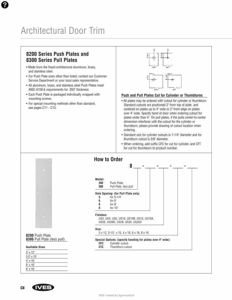
C8
Architectural Door Trim
How to Order8 ___ - ____ -____ - ____ - ____
Model: 200 Push Plate, 300 Pull Plate, less pull
Hole Spacing: (for Pull Plate only)5 for 5-1/4"6 for 6" 8 for 8"0 for 10"
Finishes: US3, US4, US5, US10, US10B, US15, US15A, US26, US26D, US28, US32, US32D
Size: 3 x 12, 3-1/2 x 15, 4 x 16, 6 x 16, 8 x 16
Special Options: (specify handing for plates over 4" wide)CFC Cylinder cutoutCTC Thumbturn cutout
8200 Series Push Plates and 8300 Series Pull Plates• Made from the finest architectural aluminum, brass,
and stainless steel.• For Push Plate sizes other than listed, contact our Customer
Service Department or your local sales representative.• All aluminum, brass, and stainless steel Push Plates meet
ANSI A156.6 requirements for .050" thickness.• Each Push Plate is packaged individually wrapped with
mounting screws.• For special mounting methods other than standard,
see pages C11 - C13.
8200 Push Plate8300 Pull Plate (less pull)
Available Sizes
3" x 12"3.5" x 15"4" x 16"6" x 16"8" x 16"
Push and Pull Plates Cut for Cylinder or Thumbturns• All plates may be ordered with cutout for cylinder or thumbturn.
Standard cutouts are positioned 2" from top of plate and centered on plates up to 4" wide or 2" from edge on plates over 4" wide. Specify hand of door when ordering cutout forplates wider than 4". On pull plates, if the pulls center-to-centerdimension interferes with the cutout for the cylinder or thumbturn, please provide drawing of cutout location whenordering.
• Standard size for cylinder cutouts is 1-1/4" diameter and forthumbturn cutout is 3/8" diameter.
• When ordering, add suffix CFC for cut for cylinder, and CFT for cut for thumbturn to product number.
PDF created by Specworks®
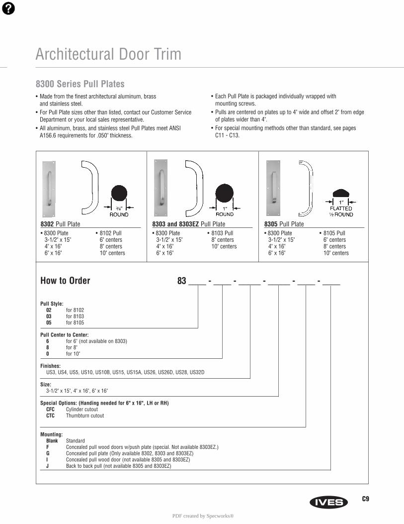
How to Order 83 ____ - ____ - _____ - _____ - ____ - ____
Pull Style:02 for 810203 for 810305 for 8105
Pull Center to Center: 6 for 6" (not available on 8303) 8 for 8"0 for 10"
Finishes: US3, US4, US5, US10, US10B, US15, US15A, US26, US26D, US28, US32D
Size:3-1/2" x 15", 4" x 16", 6" x 16"
Special Options: (Handing needed for 6" x 16", LH or RH)CFC Cylinder cutoutCTC Thumbturn cutout
Mounting: Blank Standard F Concealed pull wood doors w/push plate (special. Not available 8303EZ.)G Concealed pull plate (Only available 8302, 8303 and 8303EZ)I Concealed pull wood door (not available 8305 and 8303EZ)J Back to back pull (not available 8305 and 8303EZ)
Architectural Door Trim
• 8300 Plate3-1/2" x 15"4" x 16"6" x 16"
• 8102 Pull6" centers8" centers10" centers
8302 Pull Plate• 8300 Plate
3-1/2" x 15"4" x 16"6" x 16"
• 8103 Pull8" centers10" centers
8303 and 8303EZ Pull Plate• 8300 Plate
3-1/2" x 15"4" x 16"6" x 16"
• 8105 Pull6" centers8" centers10" centers
8305 Pull Plate
8300 Series Pull Plates• Made from the finest architectural aluminum, brass
and stainless steel.• For Pull Plate sizes other than listed, contact our Customer Service
Department or your local sales representative.• All aluminum, brass, and stainless steel Pull Plates meet ANSI
A156.6 requirements for .050" thickness.
• Each Pull Plate is packaged individually wrapped with mounting screws.
• Pulls are centered on plates up to 4" wide and offset 2" from edgeof plates wider than 4".
• For special mounting methods other than standard, see pages C11 - C13.
C9
PDF created by Specworks®
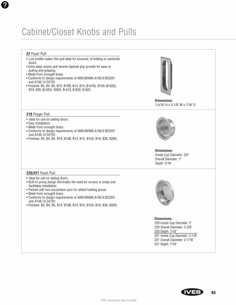
K5
Cabinet/Closet Knobs and Pulls
22 Flush Pull• Low profile makes this pull ideal for louvered, bi-folding or wardrobe
doors.• Extra deep recess and reverse tapered grip provide for ease of
pulling and gripping. • Made from wrought brass.• Conforms to design requirements of ANSI/BHMA A156.9 B22201
and A156.14 D2781.• Finishes: B3, B4, B5, B10, B10B, B14, B15 (B-619), B15A (B-620),
B19, B26 (B-625), B26D, B-619, B-620, B-625.
218 Finger Pull• Ideal for use on sliding doors.• Easy installation.• Made from wrought brass.• Conforms to design requirements of ANSI/BHMA A156.9 B22201
and A156.14 D2781.• Finishes: B3, B4, B5, B10, B10B, B14, B15, B15A, B19, B26, B26D.
220/221 Flush Pull• Ideal for use on sliding doors.• Built-in prong design eliminates the need for screws or brads and
facilitates installation. • Packed with two escutcheon pins for added holding power.• Made from wrought brass.• Conforms to design requirements of ANSI/BHMA A156.9 B22201
and A156.14 D2781.• Finishes: B3, B4, B5, B10, B10B, B14, B15, B15A, B19, B26, B26D.
Dimensions:1-5/16" H x 3-1/8" W x 7/16" D
Dimensions:Inside Cup Diameter: 3/4"Overall Diameter: 1"Depth: 5/16"
Dimensions:220 Inside Cup Diameter: 2"220 Overall Diameter: 2-3/8"220 Depth: 7/16" 221 Inside Cup Diameter: 2-1/8"221 Overall Diameter: 2-7/16"221 Depth: 7/16"
PDF created by Specworks®
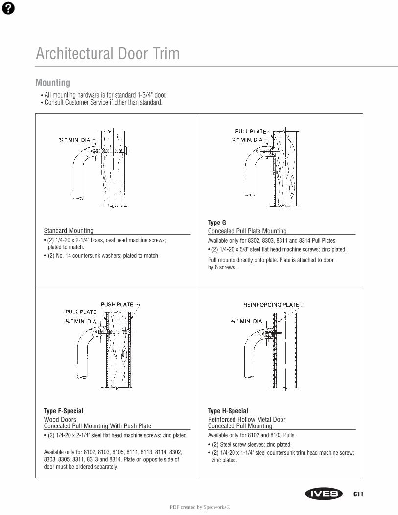
C11
Architectural Door Trim
Type F-SpecialWood DoorsConcealed Pull Mounting With Push Plate• (2) 1/4-20 x 2-1/4" steel flat head machine screws; zinc plated.
Available only for 8102, 8103, 8105, 8111, 8113, 8114, 8302, 8303, 8305, 8311, 8313 and 8314. Plate on opposite side of door must be ordered separately.
Standard Mounting• (2) 1/4-20 x 2-1/4" brass, oval head machine screws;
plated to match.• (2) No. 14 countersunk washers; plated to match
Type GConcealed Pull Plate MountingAvailable only for 8302, 8303, 8311 and 8314 Pull Plates.
• (2) 1/4-20 x 5/8" steel flat head machine screws; zinc plated.
Pull mounts directly onto plate. Plate is attached to door by 6 screws.
Type H-Special Reinforced Hollow Metal Door Concealed Pull MountingAvailable only for 8102 and 8103 Pulls.
• (2) Steel screw sleeves; zinc plated.• (2) 1/4-20 x 1-1/4" steel countersunk trim head machine screw;
zinc plated.
Mounting• All mounting hardware is for standard 1-3/4" door.• Consult Customer Service if other than standard.
PDF created by Specworks®
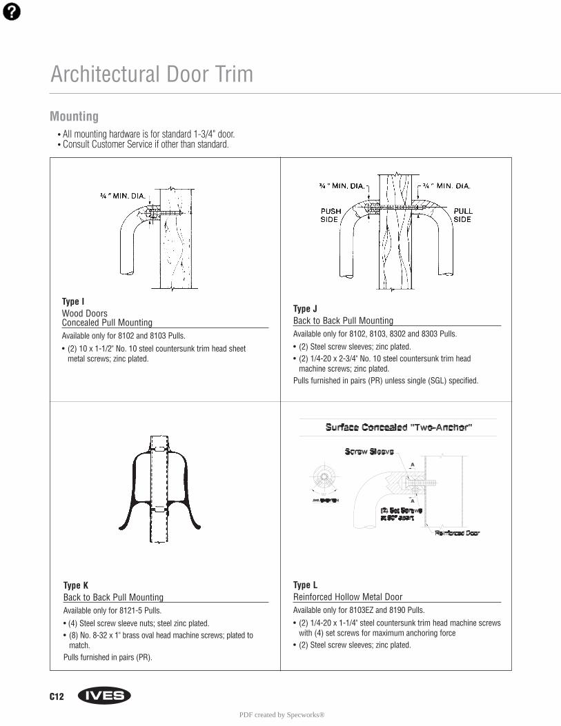
C12
Architectural Door Trim
Type KBack to Back Pull MountingAvailable only for 8121-5 Pulls.
• (4) Steel screw sleeve nuts; steel zinc plated.• (8) No. 8-32 x 1" brass oval head machine screws; plated to
match.Pulls furnished in pairs (PR).
Type IWood DoorsConcealed Pull MountingAvailable only for 8102 and 8103 Pulls.
• (2) 10 x 1-1/2" No. 10 steel countersunk trim head sheet metal screws; zinc plated.
Type JBack to Back Pull MountingAvailable only for 8102, 8103, 8302 and 8303 Pulls.
• (2) Steel screw sleeves; zinc plated.• (2) 1/4-20 x 2-3/4" No. 10 steel countersunk trim head
machine screws; zinc plated.Pulls furnished in pairs (PR) unless single (SGL) specified.
Mounting• All mounting hardware is for standard 1-3/4" door.• Consult Customer Service if other than standard.
Type LReinforced Hollow Metal DoorAvailable only for 8103EZ and 8190 Pulls.
• (2) 1/4-20 x 1-1/4" steel countersunk trim head machine screwswith (4) set screws for maximum anchoring force
• (2) Steel screw sleeves; zinc plated.
PDF created by Specworks®

C13
Type NS-Standard Push/Pull MountingType N & Standard
Pushbar to Pull- (1) 1/4-20 X 3"steel countersunk trim head machine screws with (2) set screws.- (1) steel screw sleeve, zinc plated.
Free End Pushbar & Pull- (2) 1/4-20 X 2-1/4" brass, oval head mach screws; plated to match.- (2) No. 14 countersunk washers; plated to match.
Type NO Push/Pull MountingType N & Type O
Pushbar to Pull- (1) 1/4-20 X 3"steel countersunk trim head machine screws with (2) set screws.- (1) steel screw sleeve, zinc plated.
Free End Pushbar & Pull- (2) 1/4-20 X 2-1/4" blind thru-bolts; plated to match.
Architectural Door Trim
Fastener Guide
• Through bolt fasteners are for standard 1-3/4" thick doors.
• For fasteners other than shown contact our Customer ServiceDepartment for availability.
Mounting• All mounting hardware is for standard 1-3/4" door.• Consult Customer Service if other than standard.
PDF created by Specworks®
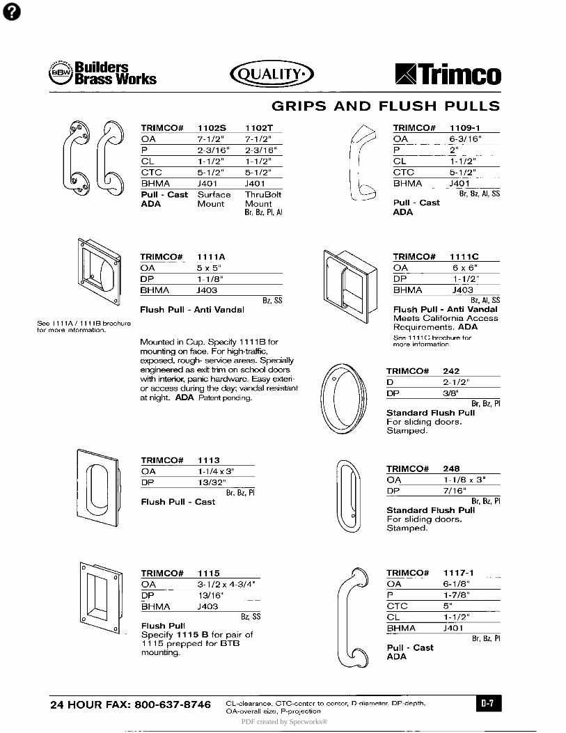
PDF created by Specworks®

A12
Coordinators - Bar Coordinators and Filler Bars
• The COR Series Coordinators are designed for use on pairs ofdoors when one door needs to close before the other.
• All COR units function easily. The active door lever, located nearestto the active stop, holds the active door open until the triggermechanism is released by the closing of the inactive leaf.
• All COR units are equipped with an override feature which allowsthe active door to close under extreme pressure.
• All COR units are compatible with Flush Bolts. • The COR Series is available in five sizes for variable
door opening widths.• The COR Series does not cover the entire length of the stop, so a
filler bar can be provided to maintain architecturally clean lines. • COR Series Coordinator Channels and fillers are made of aluminum
and are normally furnished in a US28 finish. Also available inUS26D, and 315AN (Black).
• Meets ANSI/BHMA A156.3, Type 21A.• UL Listed for installation on labeled frame.• Optional Filler Bars: FL20, FL32 and FL44, available to maintain
clean line.• Optional Mounting Brackets available: MB1, MB2, MB1F, MB2F,
MB3F, MB1V, MB2V, and MB3V for other stop applied hardware.
COR Series Bar Coordinators
For Openings Where Doors Are Same Size
Coordinator Length of For Opening CommonNumber Channel Widths Applications
COR32 32" 34" - 52" Pair of 2'0" DoorsCOR42 42" 52" - 72" Pair of 2'6" DoorsCOR52 52" 62" - 92" Pair of 3'0" DoorsCOR60 60" 70" - 108" Pair of 3'6" DoorsCOR72 72" 84" - 132" Pair of 4'0" Doors
Filler Bar Number Length
FL20 20"FL32 32"FL44 44"
Dimensions: 1-5/8" Wide x 5/8" Deep x Ordered Length
For Openings Where Doors Are Unequal Size
The coordinator length should equal the active door width plus approximately 1/2 theinactive door width. The coordinator must be 6" longer than the active door width andshorter than the overall frame opening between stops.
FL Series Filler Bars• The FL Filler Bars are available in three sizes for variable frame open-
ings.• FL Filler Bars are made of aluminum and are normally furnished
in a US28 finish. Also available in US26D and 315AN (Black).• FL Filler Bars are field sized to frame opening.
Dimensions: 1-5/8" Wide x 5/8" Deep x Ordered Length
PDF created by Specworks®
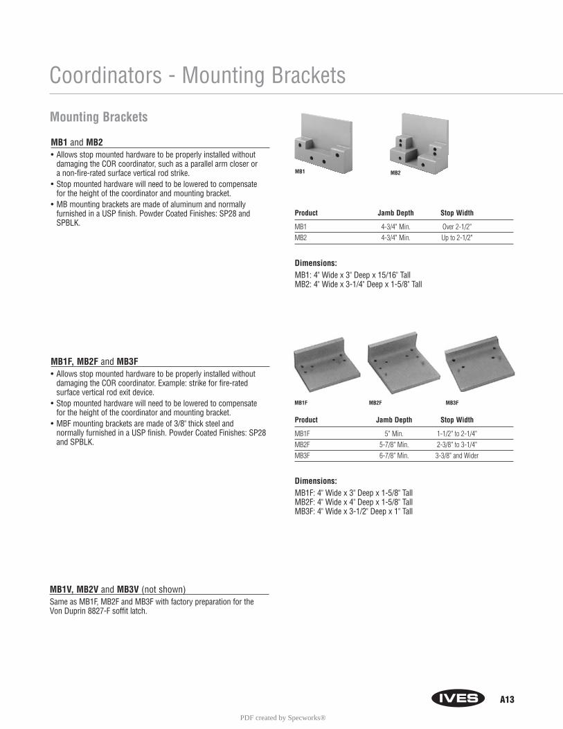
A13
Coordinators - Mounting Brackets
MB1 and MB2• Allows stop mounted hardware to be properly installed without
damaging the COR coordinator, such as a parallel arm closer or a non-fire-rated surface vertical rod strike.
• Stop mounted hardware will need to be lowered to compensate for the height of the coordinator and mounting bracket.
• MB mounting brackets are made of aluminum and normally furnished in a USP finish. Powder Coated Finishes: SP28 andSPBLK.
MB1F, MB2F and MB3F• Allows stop mounted hardware to be properly installed without
damaging the COR coordinator. Example: strike for fire-rated surface vertical rod exit device.
• Stop mounted hardware will need to be lowered to compensate for the height of the coordinator and mounting bracket.
• MBF mounting brackets are made of 3/8" thick steel and normally furnished in a USP finish. Powder Coated Finishes: SP28and SPBLK.
MB1V, MB2V and MB3V (not shown)Same as MB1F, MB2F and MB3F with factory preparation for the Von Duprin 8827-F soffit latch.
Mounting Brackets
MB1 MB2
MB1F MB2F MB3F
Product Jamb Depth Stop Width
MB1 4-3/4" Min. Over 2-1/2"MB2 4-3/4" Min. Up to 2-1/2"
Dimensions: MB1: 4" Wide x 3" Deep x 15/16" TallMB2: 4" Wide x 3-1/4" Deep x 1-5/8" Tall
Product Jamb Depth Stop Width
MB1F 5" Min. 1-1/2" to 2-1/4"MB2F 5-7/8" Min. 2-3/8" to 3-1/4"MB3F 6-7/8" Min. 3-3/8" and Wider
Dimensions: MB1F: 4" Wide x 3" Deep x 1-5/8" TallMB2F: 4" Wide x 4" Deep x 1-5/8" TallMB3F: 4" Wide x 3-1/2" Deep x 1" Tall
PDF created by Specworks®

Exit Device Exit Device Device Maximum Coordinator Coordinator Mounting BracketManufacturer Number Backset Active Door Size Needed Cutout Type Needed
Von Duprin 5547-F 2-3/8" 33" 42" A None43" 52"51" 60"63" 72"
Von Duprin 8827-F 2-3/4" 33" 42" B MB1V, MB2V43" 52" or MB3V51" 60"63" 72"
Von Duprin 8847-F 2-3/8" 33" 42" C None43" 52"51" 60"63" 72"
Von Duprin 33/3547 2-3/4" 33" 42" D None33/3547-F 43" 52"98/9947 51" 60"
98/9947-F 64" 72"Von Duprin 33/3548 2-3/4" 33" 42" D None
33/3548-F 43" 52"98/9948 51" 60"
98/9948-F 64" 72"Von Duprin 33/3547WDC 1-5/16" 34" 42" E None
33/3547WDC-F 44" 52"98/9947WDC 52" 60"
98/9947WDC-F 65" 72"Monarch 17-C 2-3/4" 33" 42" F None
F-17-C 43" 52"18-C 51" 60"
F-18-C 63" 72"XX-C
F-XX-CMonarch 17-C-WDC 2-13/16" 33" 42" G None
F-17-C-WDC 43" 52"18-C-WDC 51" 60"
F-18-C-WDC 63" 72"XX-C-WDC
F-XX-C-WDC
A14
Coordinators
Special Factory Preparation for Use with Vertical Rod Exit Devices• Coordinators may need to be prepared at the factory for use
with some surface and concealed vertical rod exit devices. (See Chart below)
• If exit device not listed in chart, the information shown on the illustration will be needed.
1. Exit Device Manufacturer and Model No.2. Active Net Door Size, “X”3. Inactive Net Door Size, “Y”4. Exit Device Backset, “U”5. Stop Width, “W”6. Stop Thickness if other than 5/8", “V”
PDF created by Specworks®
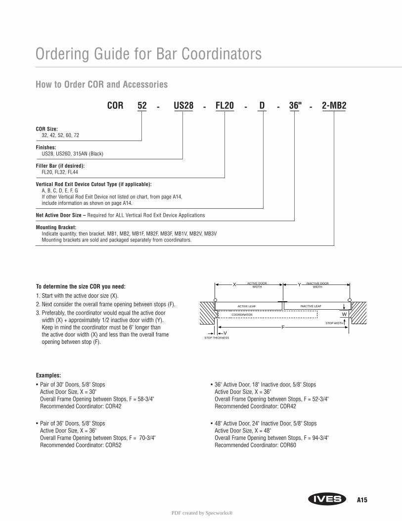
A15
Ordering Guide for Bar Coordinators
To determine the size COR you need:
1. Start with the active door size (X).2. Next consider the overall frame opening between stops (F). 3. Preferably, the coordinator would equal the active door
width (X) + approximately 1/2 inactive door width (Y). Keep in mind the coordinator must be 6" longer than the active door width (X) and less than the overall frame opening between stop (F).
Examples:
• Pair of 30" Doors, 5/8" Stops Active Door Size, X = 30"Overall Frame Opening between Stops, F = 58-3/4"Recommended Coordinator: COR42
• Pair of 36" Doors, 5/8" StopsActive Door Size, X = 36"Overall Frame Opening between Stops, F = 70-3/4"Recommended Coordinator: COR52
COORDINATOR
ACTIVE LEAF INACTIVE LEAF
ACTIVE DOORWIDTH
INACTIVE DOORWIDTH
X Y
W
VSTOP THICKNESS
STOP WIDTH
F
COR 52 US28 FL20 D 36" 2-MB2__ - ____ - ____ - __ - __ - _____
How to Order COR and Accessories
COR Size: 32, 42, 52, 60, 72
Finishes: US28, US26D, 315AN (Black)
Filler Bar (if desired): FL20, FL32, FL44
Vertical Rod Exit Device Cutout Type (if applicable): A, B, C, D, E, F, GIf other Vertical Rod Exit Device not listed on chart, from page A14,include information as shown on page A14.
Net Active Door Size – Required for ALL Vertical Rod Exit Device Applications
Mounting Bracket:Indicate quantity, then bracket. MB1, MB2, MB1F, MB2F, MB3F, MB1V, MB2V, MB3VMounting brackets are sold and packaged separately from coordinators.
• 36" Active Door, 18" Inactive door, 5/8" StopsActive Door Size, X = 36"Overall Frame Opening between Stops, F = 52-3/4"Recommended Coordinator: COR42
• 48" Active Door, 24" Inactive Door, 5/8" StopsActive Door Size, X = 48"Overall Frame Opening between Stops, F = 94-3/4"Recommended Coordinator: COR60
PDF created by Specworks®

A16
COR7G and COR9G Gravity CoordinatorsFeatures:• When active door is open, coordinator prevents active door
from closing until inactive door bypasses. Closing of inactivedoor causes strike plate on top of door to contact cam and liftarm, allowing active door to close. As inactive door continuesclosing, roller rides over strike plate on to door bracket, holdingarm above active door.
• UL Listed for Fire Doors.• Non-handed.• Gravity action arm and door bracket are adjustable on the job
for ease of installation. Nylon roller provides quiet and efficientoperation, and helps protect the astragal and doors from damage.
• Nylon roller on short arm glides smoothly over door bracket and strike, ensuring silent operation.
• Made of forged brass.• Finishes: US3, US4, US10, US10B, US26, US26D.• Meets ANSI/BHMA A156.3, Type 21.
CORG77" Projection• Use on pairs of doors with astragal on active door up to 4'.• With astragal, inactive door up to 3'4".• With astragals, both doors up to 2'10".
CORG99" Projection• Use on pairs of doors with astragal on active door over 4'.• With astragal, inactive door over 3'4".• With astragals, both doors over 2'10".
Coordinators - Gravity Coordinators
CB1 Carry BarFeatures:• Used when it is possible for the inactive door
to be opened before the active door.• Prevents damage to the doors and other hardware.• Nylon roller insures quiet and efficient operation. • Non-handed.• All-steel construction.• Finishes: USP, US3, US4, US10, US10B, US26, US26D.• Meets ANSI/BHMA A156.3, Type 21.• Standard sex bolts for mounting.
PDF created by Specworks®
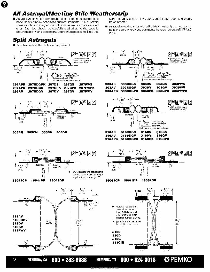
PDF created by Specworks®
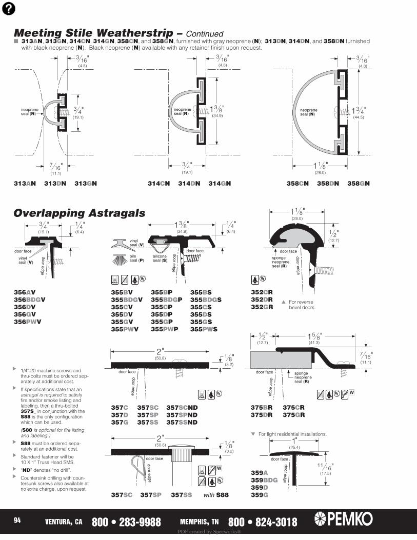
PDF created by Specworks®
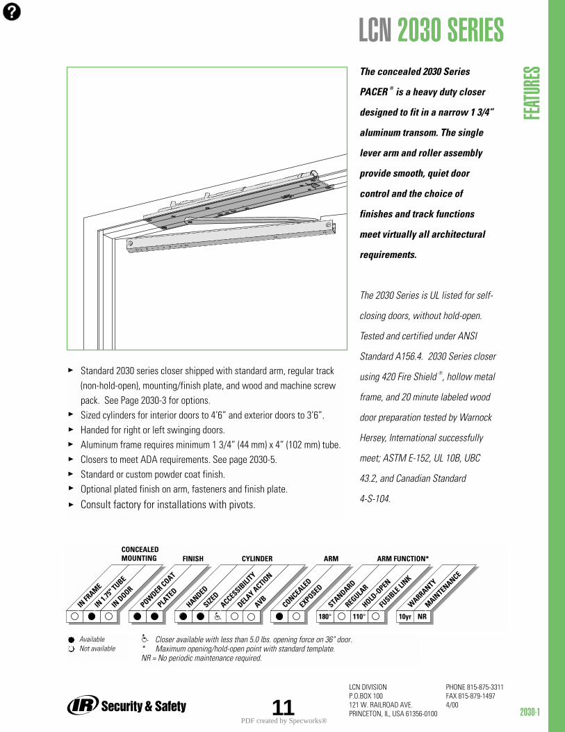
2030-1
PHONE 815-875-3311FAX 815-879-14974/00
LCN DIVISION P.O.BOX 100121 W. RAILROAD AVE.PRINCETON, IL, USA 61356-010011
Standard 2030 series closer shipped with standard arm, regular track (non-hold-open), mounting/finish plate, and wood and machine screw pack. See Page 2030-3 for options.Sized cylinders for interior doors to 4’6” and exterior doors to 3’6”.Handed for right or left swinging doors.Aluminum frame requires minimum 1 3/4” (44 mm) x 4” (102 mm) tube.Closers to meet ADA requirements. See page 2030-5.Standard or custom powder coat finish.Optional plated finish on arm, fasteners and finish plate.
Consult factory for installations with pivots.
The concealed 2030 Series
PACER ® is a heavy duty closer
designed to fit in a narrow 1 3/4”
aluminum transom. The single
lever arm and roller assembly
provide smooth, quiet door
control and the choice of
finishes and track functions
meet virtually all architectural
requirements.
The 2030 Series is UL listed for self-
closing doors, without hold-open.
Tested and certified under ANSI
Standard A156.4. 2030 Series closer
using 420 Fire Shield ®, hollow metal
frame, and 20 minute labeled wood
door preparation tested by Warnock
Hersey, International successfully
meet; ASTM E-152, UL 10B, UBC
43.2, and Canadian Standard
4-S-104.
FEATU
RES
LCN 2030 SERIES
IN FR
AME
IN 1.
75" T
UBE
IN DOOR
POWDER COAT
PLATED
STANDARD
REGULAR
HOLD-O
PEN
FUSIB
LE LI
NK
ARM FUNCTION*CONCEALEDMOUNTING FINISH
WARRANTY
MAINTENANCE
CONCEALED
EXPOSED
ARM
HANDED
SIZEDACCESSIB
ILITY
DELAY ACTIO
N
CYLINDER
AVB
10yr110°180° NR
Available Not available
Closer available with less than 5.0 lbs. opening force on 36" door.* Maximum opening/hold-open point with standard template. NR = No periodic maintenance required.
PDF created by Specworks®

2030-2
PHONE 815-875-3311FAX 815-879-14974/00
LCN DIVISION P.O.BOX 100121 W. RAILROAD AVE.PRINCETON, IL, USA 61356-0100 12
CONCEALED MOUNTINGFor interior or exterior doors.Single acting cylinder in head frame.Concealed arm and track in door top rail.
MAXIMUM OPENINGButt hinge template allows 180°,trim permitting.Limited to 110° when optionalbumper is installed.Hold-open points at 85°, 90°, 100°,or 110°, with hold-open track.
LCN Offset pivot template allows115°, trim permitting.Limited to 95° when optional bumper is installed.Hold-open points at 75°, 85°, 90°, or95°, with hold-open track.
LCN Center pivot template allows120°, trim permitting.Limited to 100° when optionalbumper is installed.Hold-open points at 85°, 90°, 95°, or 100°, with hold-open track.
LCN 2030 SERIES
Butt Hinges should not exceed 5” (127 mm) in width.
Auxiliary Stop is recommended where a door cannot swing 180°.Optional track bumper assembly assists backcheck in cushioning the opening swing of the door. It is not intended to replace an auxiliary stop.
Top Rail 1 3/8” (35 mm) mortise required.With Fire Shield, 1 13/32” (36 mm) mortise required.5/16” (8 mm) cutout required at top of the door, stop face only.
Door Thickness 1 3/4” (44 mm) minimum.
Hollow Metal Frame Consult factory for installation instructions.
Wood Frame installation simplified by WOOD MOUNTING CLIP SET 2030-416 for center pivoted or 2030-417 for offset pivoted and butt hung installations. Consult factory for preparation details.
MOUN
TING D
ETAILS
OptionsRegular track with BumperHold-open trackHold-open track with BumperFire ShieldConsult factory for installationswith pivots.
Special TemplatesCustomized installation templatesor products may be available tosolve unusual applications. ContactLCN for assistance.
PDF created by Specworks®
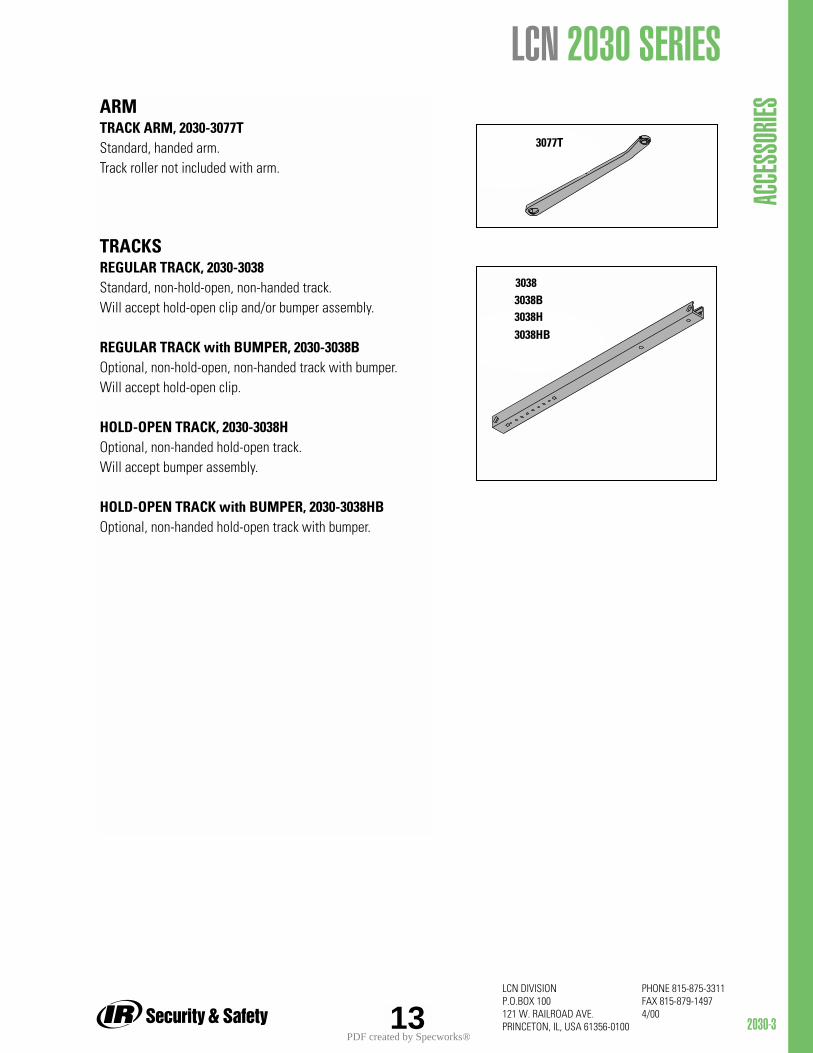
2030-3
PHONE 815-875-3311FAX 815-879-14974/00
LCN DIVISION P.O.BOX 100121 W. RAILROAD AVE.PRINCETON, IL, USA 61356-010013
LCN 2030 SERIES
ACCE
SSOR
IESARMTRACK ARM, 2030-3077TStandard, handed arm. Track roller not included with arm.
TRACKSREGULAR TRACK, 2030-3038Standard, non-hold-open, non-handed track. Will accept hold-open clip and/or bumper assembly.
REGULAR TRACK with BUMPER, 2030-3038BOptional, non-hold-open, non-handed track with bumper. Will accept hold-open clip.
HOLD-OPEN TRACK, 2030-3038HOptional, non-handed hold-open track. Will accept bumper assembly.
HOLD-OPEN TRACK with BUMPER, 2030-3038HBOptional, non-handed hold-open track with bumper.
3077T
30383038B3038H3038HB
PDF created by Specworks®
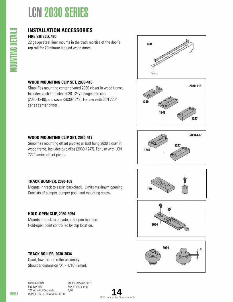
2030-4
PHONE 815-875-3311FAX 815-879-14974/00
LCN DIVISION P.O.BOX 100121 W. RAILROAD AVE.PRINCETON, IL, USA 61356-0100 14
LCN 2030 SERIES MO
UNTIN
G DETA
ILS INSTALLATION ACCESSORIESFIRE SHIELD, 42022 gauge steel liner mounts in the track mortise of the door’stop rail for 20 minute labeled wood doors.
WOOD MOUNTING CLIP SET, 2030-416Simplifies mounting center pivoted 2030 closer in wood frame.Includes latch stile clip (2030-1247), hinge stile clip(2030-1248), and cover (2030-1249). For use with LCN 7250series center pivots.
WOOD MOUNTING CLIP SET, 2030-417Simplifies mounting offset pivoted or butt hung 2030 closer inwood frame. Includes two clips (2030-1247). For use with LCN7220 series offset pivots.
TRACK BUMPER, 2030-169Mounts in track to assist backcheck. Limits maximum opening.Consists of bumper, bumper post, and mounting screw.
HOLD-OPEN CLIP, 2030-3054Mounts in track to provide hold-open function.Hold-open point controlled by clip location.
TRACK ROLLER, 2030-3034Quiet, low friction roller assembly.Shoulder dimension "X" = 1/16" (2mm).
420
169
3054
2030-416
1247
1248
1249
2030-417
12471247
3034
PDF created by Specworks®

2030-5
PHONE 815-875-3311FAX 815-879-14974/00
LCN DIVISION P.O.BOX 100121 W. RAILROAD AVE.PRINCETON, IL, USA 61356-010015
size 3 size 4 size 5
Indicates recommended range of door width for closer size.
DOOR WIDTH 36" 42" 48"
8.5* lbs. 2033 2033 20345.0* lbs. 2031 2032 2032
REDUCED OPENING FORCE 2030 CLOSERSCAUTION ! Any manual door closer, including those certified by BHMA toconform to ANSI Standard A156.4, that is selected, installed and adjustedbased on ADA or other reduced opening force requirements may not providesufficient power to reliably close and latch a door.
Refer to POWER OPERATORS section for information on systems that meetreduced opening force requirements without affecting closing power.
TABLE OF SIZES Select closer based on width of door.2030 Series cylinders available in size 1, 2, 3, 4, or 5. Closing power of all 2030 Series closers may be increased 35%. Specify next higher size closer where strong drafts exist.
2034
2033
EXTERIOR (and VESTIBULE) DOOR WIDTH
28"711mm
* Maximum opening force
30"762mm
36"914mm
42"1067mm
2035
LCN 2030 SERIES
ORDE
RING I
NFOR
MATIO
N
size 2 size 3 size 4 size 5
2033
2032
INTERIOR DOOR WIDTH
28"711mm
34"864mm
38"965mm
48"1219mm
2034
54"1372mm
2035
HOW-TO-ORDER2030 SERIES CLOSERS
1. SELECT CYLINDER SIZE20312032203320342035
2. SPECIFY HANDRHLH
3. SPECIFY FINISHStandard Powder Coat ___________ Aluminum, Statuary, Light Bronze, Tan, Brass, Black, Dark BronzeCustom Powder Coat____________Plated Finish, US ______________
Closer will be shipped with:- STANDARD ARM,- TRACK ROLLER,- REGULAR TRACK,- WOOD and MACHINE SCREW PACK,unless options listed below are selected.
CLOSER OPTIONSTRACK
Regular track with BumperHold-open trackHold-open track with Bumper
SCREW PACKTORX Machine Screw
INSTALLATION ACCESSORIESFire Shield, 420Wood Clip Set, 2030-416Wood Clip Set, 2030-417
SPECIAL TEMPLATEST- _________
MinimumDoor Width
MinimumDoor Width
PDF created by Specworks®
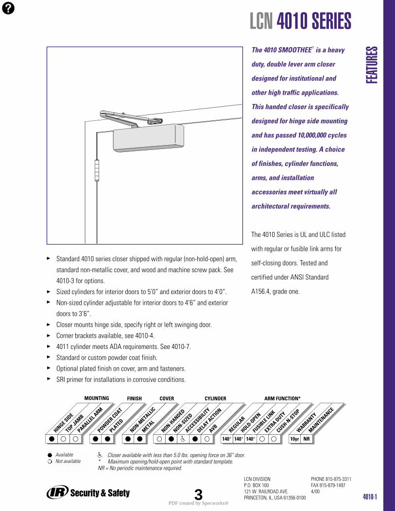
4010-1
PHONE 815-875-3311FAX 815-879-14974/00
LCN DIVISIONP.O. BOX 100121 W. RAILROAD AVE.PRINCETON, IL, USA 61356-0100
Standard 4010 series closer shipped with regular (non-hold-open) arm,
standard non-metallic cover, and wood and machine screw pack. See
4010-3 for options.
Sized cylinders for interior doors to 5’0” and exterior doors to 4’0”.
Non-sized cylinder adjustable for interior doors to 4’6” and exterior
doors to 3’6”.
Closer mounts hinge side, specify right or left swinging door.
Corner brackets available, see 4010-4.
4011 cylinder meets ADA requirements. See 4010-7.
Standard or custom powder coat finish.
Optional plated finish on cover, arm and fasteners.
SRI primer for installations in corrosive conditions.
The 4010 SMOOTHEE® is a heavy
duty, double lever arm closer
designed for institutional and
other high traffic applications.
This handed closer is specifically
designed for hinge side mounting
and has passed 10,000,000 cycles
in independent testing. A choice
of finishes, cylinder functions,
arms, and installation
accessories meet virtually all
architectural requirements.
The 4010 Series is UL and ULC listed
with regular or fusible link arms for
self-closing doors. Tested and
certified under ANSI Standard
A156.4, grade one.
FEATU
RES
LCN 4010 SERIES
HINGE SID
E
TOP JAMB
PARALLEL A
RM
POWDER COAT
PLATED
REGULAR
HOLD-O
PEN
FUSIB
LE LI
NK
ARM FUNCTION*MOUNTING FINISH
EXTRA DUTY
NON-METALL
IC
METAL
COVER
NON-HANDED
NON-SIZED
ACCESSIBILI
TY
DELAY ACTIO
N
CYLINDER
AVB
140° 140° 140° 10yr NRCUSH-N
-STOP
WARRANTY
MAINTENANCE
Available Not available
Closer available with less than 5.0 lbs. opening force on 36" door.* Maximum opening/hold-open point with standard template.NR = No periodic maintenance required.
3PDF created by Specworks®

HINGE (PULL) SIDEMOUNTING
MAXIMUM OPENINGCan be templated for 100°,
A = 6” (152 mm)B = 11 7/8” (302 mm)
120°,A = 4 3/4” (121 mm)B = 10 5/8” (270 mm)
or 140°. A = 3 1/2” (89 mm)B = 9 3/8” (238 mm)
Note: Decrease the A and Bdimensions by 1” (25mm) for 4011cylinders installed to the 140°template to meet 5 lb.-f maximumon 36’ wide door.
Hold-open points up to maximumopening with hold-open arm.
Arm Clearance above door. Regular arm requires C = 1 1/16”(27 mm).Hold-open arm requires C = 1 3/8”(35 mm).Fusible link arm requires C = 1 5/8”(41 mm).
4010-2
PHONE 815-875-3311FAX 815-879-14974/00
LCN DIVISIONP.O. BOX 100121 W. RAILROAD AVE.PRINCETON, IL, USA 61356-0100
LCN 4010 SERIES
Butt Hinges should not exceed 5” (127 mm) in width.
Auxiliary Stop is recommended at hold-open point or where a door cannot swing 140°.
Reveal should not exceed 3/4” (19 mm).
Top Rail less than 3 3/4” (95 mm) requires PLATE, 4010-18. Plate requires 2” (51 mm) minimum.
Clearance of 2 1/4” (57 mm) behind door required for 90° installation.
Delay Action Add suffix “DA” to selected cylinder (eg. 4014 DA).
Not available with 4016 cylinder.
Delays closing from maximum opening to approximately 70°.
Delay time adjustable up to approximately 1 minute.
Bull Nose Trim requires SOFFIT SHOE, 4010-65.
Corner Bracket for a door where top jamb or parallel arm mounting cannot be used. Consult factory on all corner bracket mounts.
MOUN
TING D
ETAILS
OptionsSized or non-sized cylinder.Delayed action cylinder.Hold-open, H180 (bracket mount only) hold-open, or fusible link arm.Metal or lead lined cover.
Special Templates Customized installation templatesor products may be available tosolve unusual applications.Contact LCN for assistance.
4PDF created by Specworks®
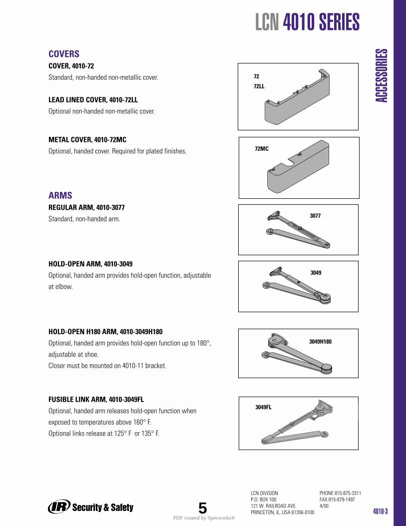
4010-3
PHONE 815-875-3311FAX 815-879-14974/00
LCN DIVISIONP.O. BOX 100121 W. RAILROAD AVE.PRINCETON, IL, USA 61356-0100
LCN 4010 SERIES
ACCE
SSOR
IESCOVERSCOVER, 4010-72
Standard, non-handed non-metallic cover.
LEAD LINED COVER, 4010-72LL
Optional non-handed non-metallic cover.
METAL COVER, 4010-72MC
Optional, handed cover. Required for plated finishes.
ARMSREGULAR ARM, 4010-3077
Standard, non-handed arm.
HOLD-OPEN ARM, 4010-3049
Optional, handed arm provides hold-open function, adjustable
at elbow.
HOLD-OPEN H180 ARM, 4010-3049H180
Optional, handed arm provides hold-open function up to 180°,
adjustable at shoe.
Closer must be mounted on 4010-11 bracket.
FUSIBLE LINK ARM, 4010-3049FL
Optional, handed arm releases hold-open function when
exposed to temperatures above 160° F.
Optional links release at 125° F or 135° F.
72
3077
72MC
3049H180
72LL
3049
3049FL
5PDF created by Specworks®
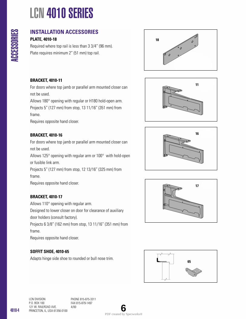
4010-4
PHONE 815-875-3311FAX 815-879-14974/00
LCN DIVISION P.O. BOX 100121 W. RAILROAD AVE.PRINCETON, IL, USA 61356-0100
LCN 4010 SERIES AC
CESS
ORIES INSTALLATION ACCESSORIES
PLATE, 4010-18
Required where top rail is less than 3 3/4” (96 mm).
Plate requires minimum 2” (51 mm) top rail.
BRACKET, 4010-11
For doors where top jamb or parallel arm mounted closer can
not be used.
Allows 180° opening with regular or H180 hold-open arm.
Projects 5” (127 mm) from stop, 13 11/16” (351 mm) from
frame.
Requires opposite hand closer.
BRACKET, 4010-16
For doors where top jamb or parallel arm mounted closer can
not be used.
Allows 125° opening with regular arm or 100° with hold-open
or fusible link arm.
Projects 5” (127 mm) from stop, 12 13/16” (325 mm) from
frame.
Requires opposite hand closer.
BRACKET, 4010-17
Allows 110° opening with regular arm.
Designed to lower closer on door for clearance of auxiliary
door holders (consult factory).
Projects 6 3/8” (162 mm) from stop, 13 11/16” (351 mm) from
frame.
Requires opposite hand closer.
SOFFIT SHOE, 4010-65
Adapts hinge side shoe to rounded or bull nose trim.
18
11
16
17
65
6PDF created by Specworks®
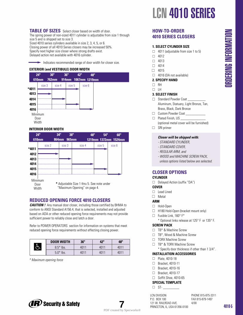
Indicates recommended range of door width for closer size.
HOW-TO-ORDER4010 SERIES CLOSERS
1. SELECT CYLINDER SIZE4011 (adjustable from size 1 to 5)40124013401440154016 (DA not available)
2. SPECIFY HANDRHLH
3. SELECT FINISHStandard Powder Coat __________Aluminum, Statuary, Light Bronze, Tan, Brass, Black, Dark BronzeCustom Powder Coat ___________Plated Finish, US ______________ (optional metal cover will be furnished)SRI primer
Closer will be shipped with:- STANDARD CYLINDER,- STANDARD COVER,- REGULAR ARM, and- WOOD and MACHINE SCREW PACK,unless options listed below are selected.
CLOSER OPTIONSCYLINDER
Delayed Action (suffix “DA”)COVER
Lead LinedMetal
ARMHold-OpenH180 Hold-Open (bracket mount only)Fusible Link, 160° F** Optional links release at 125° F or 135° F.
SCREW PACKTB* & Machine ScrewTB*, Wood & Machine ScrewTORX Machine ScrewTB* & TORX Machine Screw* Specify door thickness if other than 1 3/4”.
INSTALLATION ACCESSORIESPlate, 4010-18Bracket, 4010-11Bracket, 4010-16Bracket, 4010-17Soffit Shoe, 4010-65
SPECIAL TEMPLATEST- _________
TABLE OF SIZES Select closer based on width of door.The spring power of non-sized 4011 cylinder is adjustable from size 1 throughsize 5 and is shipped set to size 3. Sized 4010 series cylinders available in size 2, 3, 4, 5, or 6. Closing power of all 4010 Series closers may be increased 50%.Specify next higher size closer where strong drafts exist.Delayed action not available with 4016 cylinder.
size 3 size 4 size 5 size 6
4013*4011
EXTERIOR (and VESTIBULE) DOOR WIDTH
24"610mm
30"762mm
36"914mm
42"1067mm
4014
INTERIOR DOOR WIDTH
48"1219mm
24"610mm
34"864mm
38"965mm
48"1219mm
54"1372mm
60"1524mm
40154016
size 2 size 3 size 4 size 5 size 6
4013
*4011
401440154016
4012
* Adjustable Size 1 thru 5. See note under “Maximum Opening” on page 4.
DOOR WIDTH 36" 42" 48"
8.5* lbs. 4011 4011 40115.0* lbs. 4011 4011 4011
REDUCED OPENING FORCE 4010 CLOSERSCAUTION ! Any manual door closer, including those certified by BHMA toconform to ANSI Standard A156.4, that is selected, installed and adjustedbased on ADA or other reduced opening force requirements may not providesufficient power to reliably close and latch a door.
Refer to POWER OPERATORS section for information on systems that meetreduced opening force requirements without effecting closing power.
* Maximum opening force
4010-5
PHONE 815-875-3311FAX 815-879-14974/00
LCN DIVISIONP.O. BOX 100121 W. RAILROAD AVE.PRINCETON, IL, USA 61356-0100
LCN 4010 SERIES
ORDE
RING I
NFOR
MATIO
N
MinimumDoor
Width
MinimumDoor
Width
7PDF created by Specworks®

Standard 4010T series closer shipped with standard arm, regular track (non-hold-open), track roller, standard non-metallic cover, and wood andmachine screw pack. See 4010T-3 for options.Sized cylinders for interior doors to 4’0”.Closer mounts hinge side, specify right or left swinging door.Closers to meet ADA requirements. See 4010T-5.Standard or custom powder coat finish.Optional plated finish on cover, arm and fasteners.SRI primer for installations in corrosive conditions.4010T-DE available for double egress frames. See 4010T-5
4010T-1
PHONE 815-875-3311FAX 815-879-14974/00
LCN DIVISION P.O. BOX 100121 W. RAILROAD AVE.PRINCETON, IL, USA 61356-0100
The 4010T SMOOTHEE® is a heavy
duty, single lever (track) arm
closer designed for institutional
and other high traffic
applications. This handed closer
is specifically designed for
interior doors.
A choice of finishes, track
functions, and installation
accessories meet virtually all
architectural requirements.
The 4010T Series is UL and ULC
listed with a regular arm for self-
closing doors. Tested and certified
under ANSI Standard A156.4, grade
one.
FEATU
RES
LCN 4010T SERIES
HINGE SID
E
TOP JAMB
PARALELL
ARM
POWDER COAT
PLATED
REGULAR
HOLD-O
PEN
FUSIB
LE LI
NK
ARM FUNCTION*MOUNTING FINISH
EXTRA DUTY
NON-METALL
IC
METAL
COVER
NON-HANDED
NON-SIZED
ACCESSIBILI
TY
DELAY ACTIO
N
CYLINDER
AVB
180° 100° 10yr NRCUSH-N
-STOP
WARRANTY
MAINTENANCE
Available Not available
Closer available with less than 5.0 lbs. opening force on 36" door.* Maximum opening with standard template. NR = No periodic maintenance required.
9PDF created by Specworks®
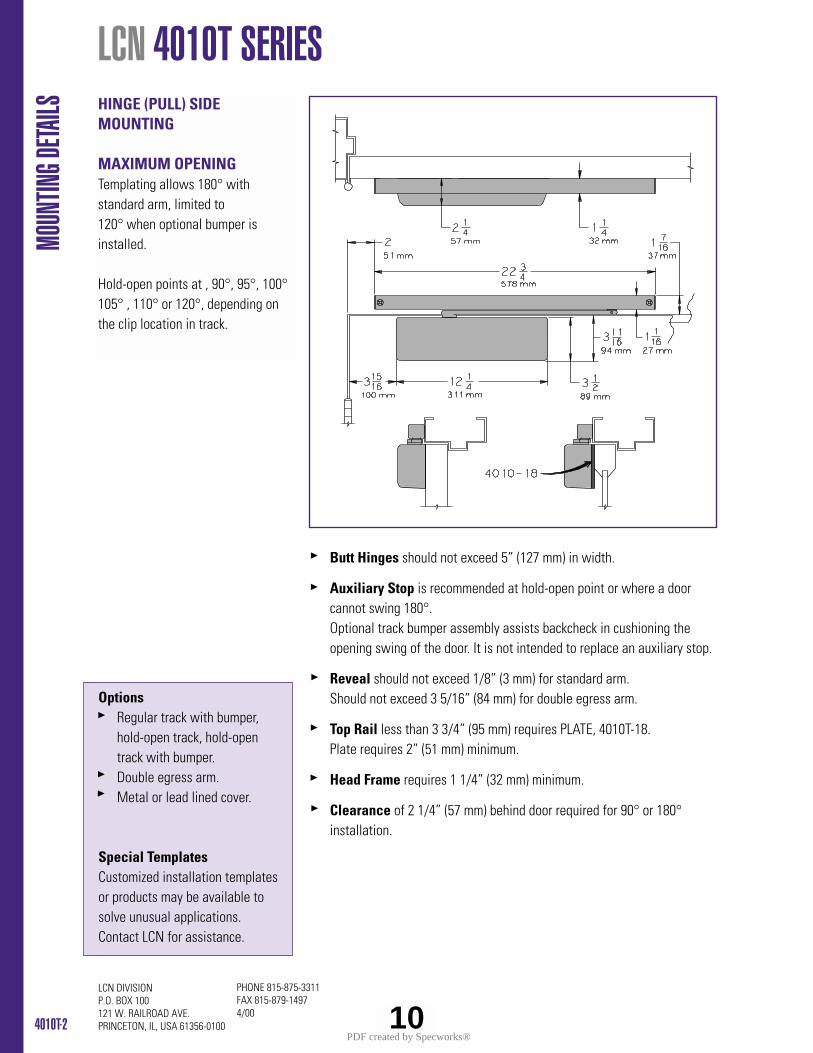
4010T-2
PHONE 815-875-3311FAX 815-879-14974/00
LCN DIVISIONP.O. BOX 100121 W. RAILROAD AVE.PRINCETON, IL, USA 61356-0100
HINGE (PULL) SIDEMOUNTING
MAXIMUM OPENINGTemplating allows 180° with standard arm, limited to 120° when optional bumper isinstalled.
Hold-open points at , 90°, 95°, 100°105° , 110° or 120°, depending onthe clip location in track.
LCN 4010T SERIES
Butt Hinges should not exceed 5” (127 mm) in width.
Auxiliary Stop is recommended at hold-open point or where a door cannot swing 180°.Optional track bumper assembly assists backcheck in cushioning the opening swing of the door. It is not intended to replace an auxiliary stop.
Reveal should not exceed 1/8” (3 mm) for standard arm.Should not exceed 3 5/16” (84 mm) for double egress arm.
Top Rail less than 3 3/4” (95 mm) requires PLATE, 4010T-18. Plate requires 2” (51 mm) minimum.
Head Frame requires 1 1/4” (32 mm) minimum.
Clearance of 2 1/4” (57 mm) behind door required for 90° or 180°installation.
MOUN
TING D
ETAILS
OptionsRegular track with bumper, hold-open track, hold-open track with bumper.Double egress arm.Metal or lead lined cover.
Special TemplatesCustomized installation templatesor products may be available tosolve unusual applications.Contact LCN for assistance.
10PDF created by Specworks®

4010T-3
PHONE 815-875-3311FAX 815-879-14974/00
LCN DIVISION P.O. BOX 100121 W. RAILROAD AVE.PRINCETON, IL, USA 61356-0100
LCN 4010T SERIES
ACCE
SSOR
IESCOVERSCOVER, 4010-72Standard, non-handed non-metallic cover.
LEAD LINED COVER, 4010-72LLOptional non-handed non-metallic cover.
METAL COVER, 4010-72MCOptional, handed cover. Required for plated finishes.
ARMSSTANDARD ARM, 4010-3077TStandard, handed arm.Arm does not include track roller.
DOUBLE EGRESS ARM, 4010-3077DEOptional, handed arm for double egress doors and frames.Arm does not include track roller. For maximum reveal see 4010T-2.
TRACKSREGULAR TRACK, 4010T-3038Standard, non-hold-open, non-handed track.Will accept hold-open clip and/or bumper assembly.
REGULAR TRACK with BUMPER, 4010T-3038BOptional non-hold-open, non-handed track with bumperassembly installed. Will accept hold-open clip.
HOLD-OPEN TRACK, 4010T-3038HOptional, non-handed track with hold-open clip installed.Will accept bumper assembly.
HOLD-OPEN TRACK with BUMPER, 4010T-3038HBOptional, non-handed track with hold-open clip and bumperassembly installed.
3077T
3077DE
3038
72LL
72MC
72
3038B
3038H
3038HB
11PDF created by Specworks®
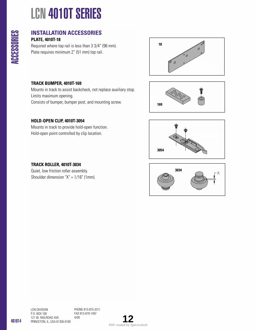
4010T-4
PHONE 815-875-3311FAX 815-879-14974/00
LCN DIVISIONP.O. BOX 100121 W. RAILROAD AVE.PRINCETON, IL, USA 61356-0100
LCN 4010T SERIES AC
CESS
ORIES
3034
INSTALLATION ACCESSORIESPLATE, 4010T-18Required where top rail is less than 3 3/4” (96 mm). Plate requires minimum 2” (51 mm) top rail.
TRACK BUMPER, 4010T-169Mounts in track to assist backcheck, not replace auxiliary stop.Limits maximum opening.Consists of bumper, bumper post, and mounting screw.
HOLD-OPEN CLIP, 4010T-3054Mounts in track to provide hold-open function.Hold-open point controlled by clip location.
TRACK ROLLER, 4010T-3034Quiet, low friction roller assembly.Shoulder dimension "X" = 1/16" (1mm).
3054
169
18
12PDF created by Specworks®
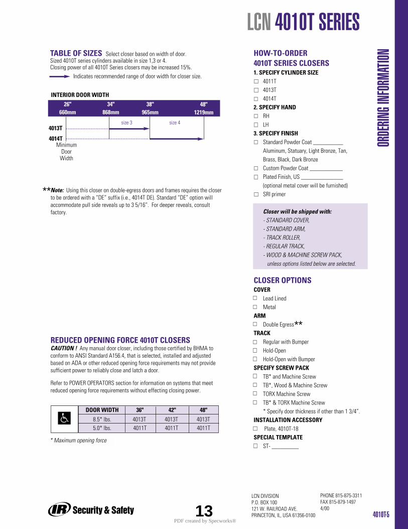
4010T-5
PHONE 815-875-3311FAX 815-879-14974/00
LCN DIVISION P.O. BOX 100121 W. RAILROAD AVE.PRINCETON, IL, USA 61356-0100
Indicates recommended range of door width for closer size.
REDUCED OPENING FORCE 4010T CLOSERSCAUTION ! Any manual door closer, including those certified by BHMA toconform to ANSI Standard A156.4, that is selected, installed and adjustedbased on ADA or other reduced opening force requirements may not providesufficient power to reliably close and latch a door.
Refer to POWER OPERATORS section for information on systems that meetreduced opening force requirements without effecting closing power.
Note: Using this closer on double-egress doors and frames requires the closerto be ordered with a “DE” suffix (i.e., 4014T DE). Standard “DE” option willaccommodate pull side reveals up to 3 5/16”. For deeper reveals, consultfactory.
TABLE OF SIZES Select closer based on width of door.Sized 4010T series cylinders available in size 1,3 or 4. Closing power of all 4010T Series closers may be increased 15%.
* Maximum opening force
HOW-TO-ORDER 4010T SERIES CLOSERS1. SPECIFY CYLINDER SIZE
4011T4013T4014T
2. SPECIFY HANDRHLH
3. SPECIFY FINISHStandard Powder Coat __________Aluminum, Statuary, Light Bronze, Tan, Brass, Black, Dark BronzeCustom Powder Coat ___________Plated Finish, US ______________(optional metal cover will be furnished)SRI primer
Closer will be shipped with:- STANDARD COVER,- STANDARD ARM,- TRACK ROLLER,- REGULAR TRACK,- WOOD & MACHINE SCREW PACK,
unless options listed below are selected.
CLOSER OPTIONSCOVER
Lead LinedMetal
ARMDouble Egress
TRACKRegular with BumperHold-OpenHold-Open with Bumper
SPECIFY SCREW PACKTB* and Machine ScrewTB*, Wood & Machine ScrewTORX Machine ScrewTB* & TORX Machine Screw* Specify door thickness if other than 1 3/4”.
INSTALLATION ACCESSORYPlate, 4010T-18
SPECIAL TEMPLATEST- _________
LCN 4010T SERIES
ORDE
RING I
NFOR
MATIO
N
size 3 size 4
4014T
4013T
INTERIOR DOOR WIDTH
26"660mm
34"868mm
38"965mm
48"1219mm
DOOR WIDTH 36" 42" 48"
8.5* lbs. 4013T 4013T 4013T5.0* lbs. 4011T 4011T 4011T
13
MinimumDoor
Width
**
**
PDF created by Specworks®
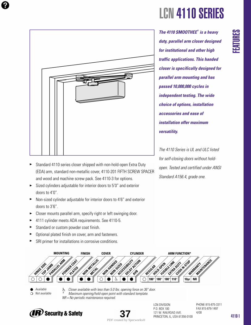
4110-1
PHONE 815-875-3311FAX 815-879-14974/00
LCN DIVISIONP.O. BOX 100121 W. RAILROAD AVE.PRINCETON, IL, USA 61356-0100
Standard 4110 series closer shipped with non-hold-open Extra Duty
(EDA) arm, standard non-metallic cover, 4110-201 FIFTH SCREW SPACER
and wood and machine screw pack. See 4110-3 for options.
Sized cylinders adjustable for interior doors to 5’0” and exterior
doors to 4’0”.
Non-sized cylinder adjustable for interior doors to 4’6” and exterior
doors to 3’6”.
Closer mounts parallel arm, specify right or left swinging door.
4111 cylinder meets ADA requirements. See 4110-5.
Standard or custom powder coat finish.
Optional plated finish on cover, arm and fasteners.
SRI primer for installations in corrosive conditions.
The 4110 SMOOTHEE® is a heavy
duty, parallel arm closer designed
for institutional and other high
traffic applications. This handed
closer is specifically designed for
parallel arm mounting and has
passed 10,000,000 cycles in
independent testing. The wide
choice of options, installation
accessories and ease of
installation offer maximum
versatility.
The 4110 Series is UL and ULC listed
for self-closing doors without hold-
open. Tested and certified under ANSI
Standard A156.4, grade one.
FEATU
RES
LCN 4110 SERIES
HINGE SID
E
TOP JAMB
PARALLEL A
RM
POWDER COAT
PLATED
REGULAR
HOLD-O
PEN
FUSIB
LE LI
NK
ARM FUNCTION*MOUNTING FINISH
EXTRA DUTY
NON-METALL
IC
METAL
COVER
NON-HANDED
NON-SIZED
ACCESSIBILI
TY
DELAY ACTIO
N
CYLINDER
AVB
180° 180° 10yr NRCUSH-N
-STOP
WARRANTY
MAINTENANCE
110°180°
Available Not available
Closer available with less than 5.0 lbs. opening force on 36" door.* Maximum opening/hold-open point with standard template.NR = No periodic maintenance required.
37PDF created by Specworks®
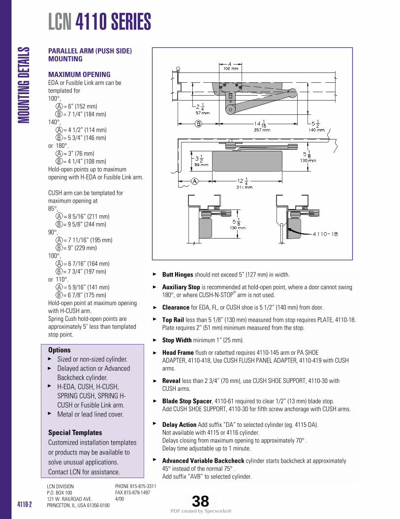
4110-2
PHONE 815-875-3311FAX 815-879-14974/00
LCN DIVISIONP.O. BOX 100121 W. RAILROAD AVE.PRINCETON, IL, USA 61356-0100
PARALLEL ARM (PUSH SIDE)MOUNTING
MAXIMUM OPENINGEDA or Fusible Link arm can betemplated for100°,
A = 6” (152 mm) B = 7 1/4” (184 mm)
140°, A = 4 1/2” (114 mm) B = 5 3/4” (146 mm)
or 180°. A = 3” (76 mm) B = 4 1/4” (108 mm)
Hold-open points up to maximumopening with H-EDA or Fusible Link arm.
CUSH arm can be templated formaximum opening at85°,
A = 8 5/16” (211 mm) B = 9 5/8” (244 mm)
90°, A = 7 11/16” (195 mm) B = 9” (229 mm)
100°, A = 6 7/16” (164 mm) B = 7 3/4” (197 mm)
or 110°. A = 5 9/16” (141 mm) B = 6 7/8” (175 mm)
Hold-open point at maximum openingwith H-CUSH arm. Spring Cush hold-open points areapproximately 5˚ less than templatedstop point.
LCN 4110 SERIES
Butt Hinges should not exceed 5” (127 mm) in width.
Auxiliary Stop is recommended at hold-open point, where a door cannot swing180°, or where CUSH-N-STOP® arm is not used.
Clearance for EDA, FL, or CUSH shoe is 5 1/2” (140 mm) from door.
Top Rail less than 5 1/8” (130 mm) measured from stop requires PLATE, 4110-18. Plate requires 2” (51 mm) minimum measured from the stop.
Stop Width minimum 1” (25 mm).
Head Frame flush or rabetted requires 4110-145 arm or PA SHOE ADAPTER, 4110-418, Use CUSH FLUSH PANEL ADAPTER, 4110-419 with CUSH arms.
Reveal less than 2 3/4” (70 mm), use CUSH SHOE SUPPORT, 4110-30 with CUSH arms.
Blade Stop Spacer, 4110-61 required to clear 1/2” (13 mm) blade stop. Add CUSH SHOE SUPPORT, 4110-30 for fifth screw anchorage with CUSH arms.
Delay Action Add suffix “DA” to selected cylinder (eg. 4115 DA).Not available with 4115 or 4116 cylinder. Delays closing from maximum opening to approximately 70° .Delay time adjustable up to 1 minute.
Advanced Variable Backcheck cylinder starts backcheck at approximately 45° instead of the normal 75° .Add suffix “AVB” to selected cylinder.
MOUN
TING D
ETAILS
OptionsSized or non-sized cylinder.Delayed action or Advanced Backcheck cylinder.H-EDA, CUSH, H-CUSH, SPRING CUSH, SPRING H-CUSH or Fusible Link arm.Metal or lead lined cover.
Special Templates Customized installation templatesor products may be available tosolve unusual applications.Contact LCN for assistance.
38PDF created by Specworks®
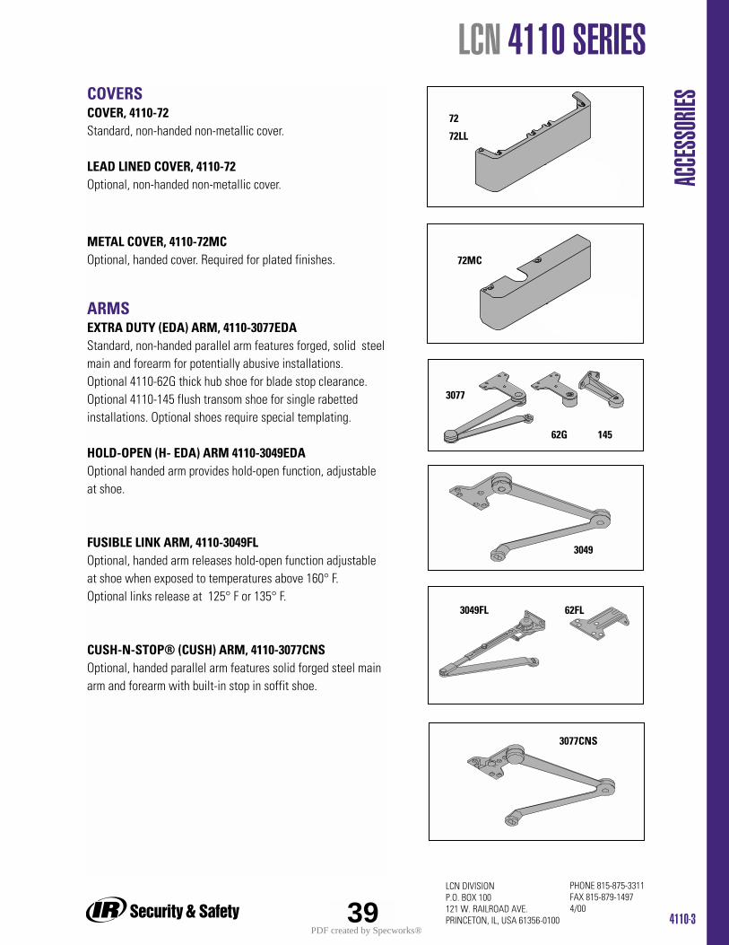
4110-3
PHONE 815-875-3311FAX 815-879-14974/00
LCN DIVISIONP.O. BOX 100121 W. RAILROAD AVE.PRINCETON, IL, USA 61356-0100
LCN 4110 SERIES
ACCE
SSOR
IESCOVERSCOVER, 4110-72Standard, non-handed non-metallic cover.
LEAD LINED COVER, 4110-72Optional, non-handed non-metallic cover.
METAL COVER, 4110-72MCOptional, handed cover. Required for plated finishes.
ARMSEXTRA DUTY (EDA) ARM, 4110-3077EDAStandard, non-handed parallel arm features forged, solid steelmain and forearm for potentially abusive installations.Optional 4110-62G thick hub shoe for blade stop clearance.Optional 4110-145 flush transom shoe for single rabettedinstallations. Optional shoes require special templating.
HOLD-OPEN (H- EDA) ARM 4110-3049EDAOptional handed arm provides hold-open function, adjustableat shoe.
FUSIBLE LINK ARM, 4110-3049FLOptional, handed arm releases hold-open function adjustableat shoe when exposed to temperatures above 160° F.Optional links release at 125° F or 135° F.
CUSH-N-STOP® (CUSH) ARM, 4110-3077CNSOptional, handed parallel arm features solid forged steel mainarm and forearm with built-in stop in soffit shoe.
72
3077
72MC
3049FL 62FL
72LL
3049
62G 145
39
3077CNS
PDF created by Specworks®
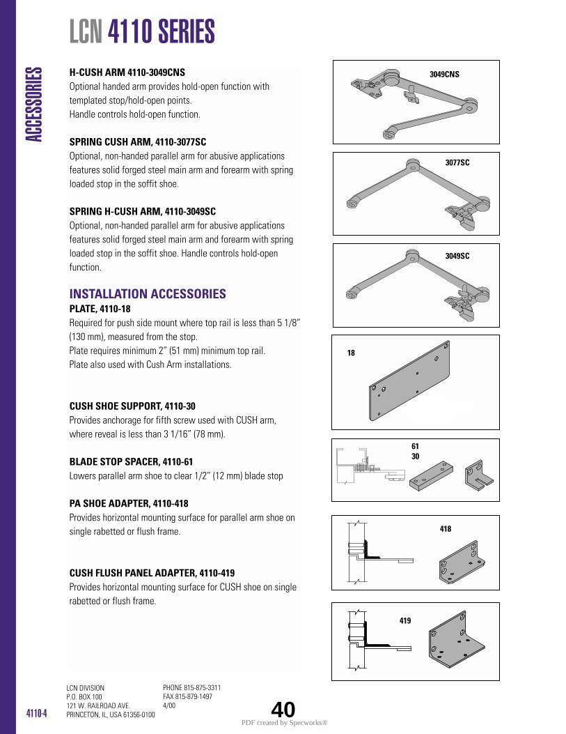
4110-4
PHONE 815-875-3311FAX 815-879-14974/00
LCN DIVISIONP.O. BOX 100121 W. RAILROAD AVE.PRINCETON, IL, USA 61356-0100
ACCE
SSOR
IES H-CUSH ARM 4110-3049CNSOptional handed arm provides hold-open function withtemplated stop/hold-open points.Handle controls hold-open function.
SPRING CUSH ARM, 4110-3077SCOptional, non-handed parallel arm for abusive applicationsfeatures solid forged steel main arm and forearm with springloaded stop in the soffit shoe.
SPRING H-CUSH ARM, 4110-3049SCOptional, non-handed parallel arm for abusive applicationsfeatures solid forged steel main arm and forearm with springloaded stop in the soffit shoe. Handle controls hold-openfunction.
INSTALLATION ACCESSORIESPLATE, 4110-18Required for push side mount where top rail is less than 5 1/8”(130 mm), measured from the stop. Plate requires minimum 2” (51 mm) minimum top rail.Plate also used with Cush Arm installations.
CUSH SHOE SUPPORT, 4110-30Provides anchorage for fifth screw used with CUSH arm,where reveal is less than 3 1/16” (78 mm).
BLADE STOP SPACER, 4110-61Lowers parallel arm shoe to clear 1/2” (12 mm) blade stop
PA SHOE ADAPTER, 4110-418Provides horizontal mounting surface for parallel arm shoe onsingle rabetted or flush frame.
CUSH FLUSH PANEL ADAPTER, 4110-419Provides horizontal mounting surface for CUSH shoe on singlerabetted or flush frame.
18
6130
418
419
LCN 4110 SERIES 3049CNS
40
3077SC
3049SC
PDF created by Specworks®
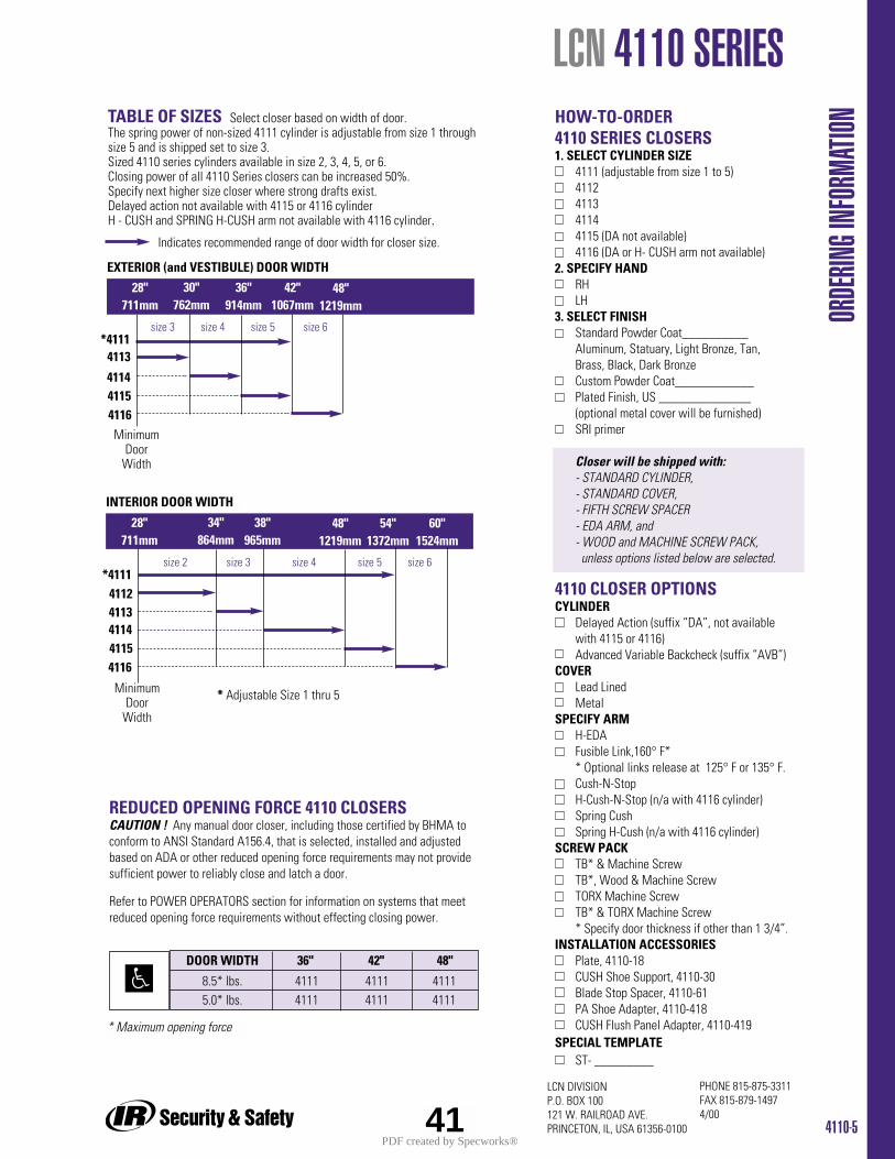
HOW-TO-ORDER4110 SERIES CLOSERS1. SELECT CYLINDER SIZE
4111 (adjustable from size 1 to 5)4112411341144115 (DA not available)4116 (DA or H- CUSH arm not available)
2. SPECIFY HANDRHLH
3. SELECT FINISHStandard Powder Coat__________Aluminum, Statuary, Light Bronze, Tan, Brass, Black, Dark BronzeCustom Powder Coat____________Plated Finish, US ______________ (optional metal cover will be furnished)SRI primer
Closer will be shipped with:- STANDARD CYLINDER,- STANDARD COVER,- FIFTH SCREW SPACER- EDA ARM, and- WOOD and MACHINE SCREW PACK,unless options listed below are selected.
4110 CLOSER OPTIONSCYLINDER
Delayed Action (suffix “DA”, not available with 4115 or 4116)Advanced Variable Backcheck (suffix “AVB”)
COVERLead LinedMetal
SPECIFY ARMH-EDAFusible Link,160° F** Optional links release at 125° F or 135° F. Cush-N-StopH-Cush-N-Stop (n/a with 4116 cylinder)Spring CushSpring H-Cush (n/a with 4116 cylinder)
SCREW PACKTB* & Machine ScrewTB*, Wood & Machine ScrewTORX Machine ScrewTB* & TORX Machine Screw* Specify door thickness if other than 1 3/4”.
INSTALLATION ACCESSORIESPlate, 4110-18CUSH Shoe Support, 4110-30Blade Stop Spacer, 4110-61PA Shoe Adapter, 4110-418CUSH Flush Panel Adapter, 4110-419
SPECIAL TEMPLATEST- _________
4110-5
PHONE 815-875-3311FAX 815-879-14974/00
LCN DIVISIONP.O. BOX 100121 W. RAILROAD AVE.PRINCETON, IL, USA 61356-0100
LCN 4110 SERIES
ORDE
RING I
NFOR
MATIO
N
Indicates recommended range of door width for closer size.
TABLE OF SIZES Select closer based on width of door.The spring power of non-sized 4111 cylinder is adjustable from size 1 throughsize 5 and is shipped set to size 3.Sized 4110 series cylinders available in size 2, 3, 4, 5, or 6.Closing power of all 4110 Series closers can be increased 50%.Specify next higher size closer where strong drafts exist.Delayed action not available with 4115 or 4116 cylinderH - CUSH and SPRING H-CUSH arm not available with 4116 cylinder.
size 3 size 4 size 5 size 6
4113*4111
EXTERIOR (and VESTIBULE) DOOR WIDTH
28"711mm
30"762mm
36"914mm
42"1067mm
4114
INTERIOR DOOR WIDTH
48"1219mm
28"711mm
34"864mm
38"965mm
48"1219mm
54"1372mm
60"1524mm
41154116
size 2 size 3 size 4 size 5 size 6
4113
*4111
411441154116
4112
* Adjustable Size 1 thru 5
DOOR WIDTH 36" 42" 48"
8.5* lbs. 4111 4111 41115.0* lbs. 4111 4111 4111
REDUCED OPENING FORCE 4110 CLOSERSCAUTION ! Any manual door closer, including those certified by BHMA toconform to ANSI Standard A156.4, that is selected, installed and adjustedbased on ADA or other reduced opening force requirements may not providesufficient power to reliably close and latch a door.
Refer to POWER OPERATORS section for information on systems that meetreduced opening force requirements without effecting closing power.
* Maximum opening force
41
MinimumDoor
Width
MinimumDoor
Width
PDF created by Specworks®
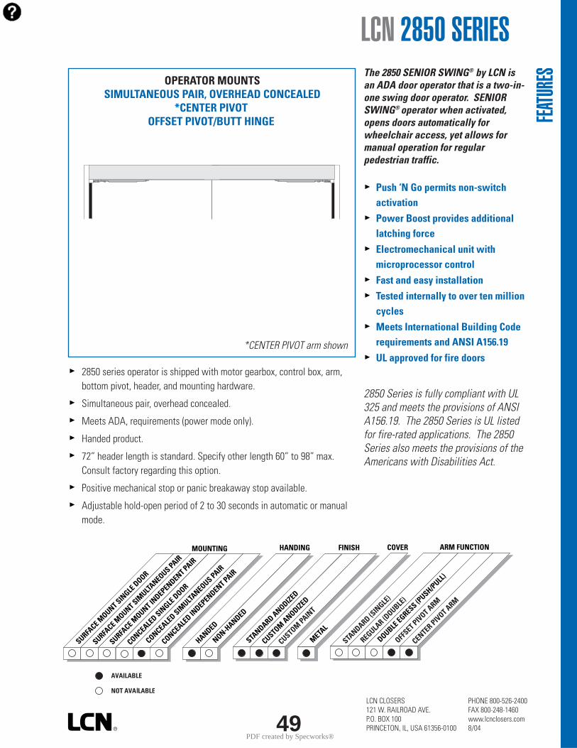
LCN CLOSERS121 W. RAILROAD AVE.P.O. BOX 100PRINCETON, IL, USA 61356-0100
PHONE 800-526-2400FAX 800-248-1460www.lcnclosers.com8/0449
LCN 2850 SERIES
STANDARD ANODIZED
CUSTOM ANODIZED
CUSTOM PAINT
FINISHHANDING
HANDED
NON-HANDED
COVER
METAL
ARM FUNCTION
STANDARD (S
INGLE
)
REGULAR (D
OUBLE)
OFFSET PIVOT ARM
CENTER PIVOT ARM
DOUBLE EGRESS (P
USH/PULL)
MOUNTING
SURFACE M
OUNT SINGLE
DOOR
SURFACE M
OUNT SIMULTA
NEOUS PAIR
SURFACE M
OUNT INDEPENDENT PAIR
CONCEALED SIN
GLE DOOR
CONCEALED IN
DEPENDENT PAIR
CONCEALED SIM
ULTANEOUS PAIR
The 2850 SENIOR SWING® by LCN isan ADA door operator that is a two-in-one swing door operator. SENIORSWING® operator when activated,opens doors automatically forwheelchair access, yet allows formanual operation for regularpedestrian traffic.
Push ‘N Go permits non-switchactivationPower Boost provides additionallatching forceElectromechanical unit withmicroprocessor controlFast and easy installationTested internally to over ten millioncyclesMeets International Building Coderequirements and ANSI A156.19UL approved for fire doors
2850 Series is fully compliant with UL325 and meets the provisions of ANSIA156.19. The 2850 Series is UL listedfor fire-rated applications. The 2850Series also meets the provisions of theAmericans with Disabilities Act.
2850 series operator is shipped with motor gearbox, control box, arm,bottom pivot, header, and mounting hardware.
Simultaneous pair, overhead concealed.
Meets ADA, requirements (power mode only).
Handed product.
72” header length is standard. Specify other length 60” to 98” max.Consult factory regarding this option.
Positive mechanical stop or panic breakaway stop available.
Adjustable hold-open period of 2 to 30 seconds in automatic or manualmode.
OPERATOR MOUNTSSIMULTANEOUS PAIR, OVERHEAD CONCEALED
*CENTER PIVOTOFFSET PIVOT/BUTT HINGE FEA
TURE
S
*CENTER PIVOT arm shown
PDF created by Specworks®
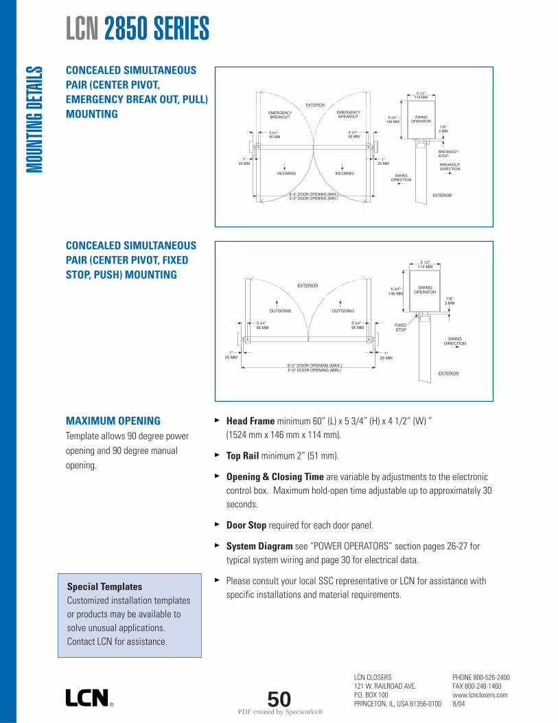
LCN CLOSERS121 W. RAILROAD AVE.P.O. BOX 100PRINCETON, IL, USA 61356-0100
PHONE 800-526-2400FAX 800-248-1460www.lcnclosers.com8/0450
Head Frame minimum 60” (L) x 5 3/4” (H) x 4 1/2” (W) ”(1524 mm x 146 mm x 114 mm).
Top Rail minimum 2” (51 mm).
Opening & Closing Time are variable by adjustments to the electroniccontrol box. Maximum hold-open time adjustable up to approximately 30seconds.
Door Stop required for each door panel.
System Diagram see “POWER OPERATORS” section pages 26-27 fortypical system wiring and page 30 for electrical data.
Please consult your local SSC representative or LCN for assistance withspecific installations and material requirements.
CONCEALED SIMULTANEOUSPAIR (CENTER PIVOT,EMERGENCY BREAK OUT, PULL)MOUNTING
CONCEALED SIMULTANEOUSPAIR (CENTER PIVOT, FIXEDSTOP, PUSH) MOUNTING
MAXIMUM OPENINGTemplate allows 90 degree poweropening and 90 degree manualopening.
LCN 2850 SERIES
Special TemplatesCustomized installation templatesor products may be available tosolve unusual applications. Contact LCN for assistance.
MOUN
TING D
ETAILS
3 3/4"95 MM
8'-0" DOOR OPENING (MAX.)5'-0" DOOR OPENING (MIN.)
SWINGOPERATOR
4 1/2"114 MM
5 3/4"146 MM
SWINGDIRECTION
EXTERIOR
INCOMING INCOMING
3 3/4"95 MM
1"25 MM
1"25 MM
EXTERIOR
EMERGENCYBREAKOUT
EMERGENCYBREAKOUT
1/8"3 MM
BREAKOUTDIRECTION
BREAKOUTSTOP
3 3/4"95 MM
8'-0" DOOR OPENING (MAX.)5'-0" DOOR OPENING (MIN.)
SWINGOPERATOR
4 1/2"114 MM
5 3/4"146 MM
SWINGDIRECTION
EXTERIOR
3 3/4"95 MM
1"25 MM
1"25 MM
EXTERIOR
1/8"3 MM
OUTGOING OUTGOING
FIXEDSTOP
PDF created by Specworks®
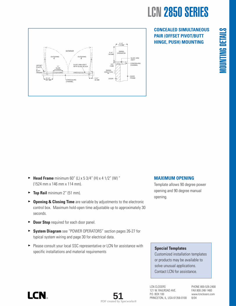
LCN CLOSERS121 W. RAILROAD AVE.P.O. BOX 100PRINCETON, IL, USA 61356-0100
PHONE 800-526-2400FAX 800-248-1460www.lcnclosers.com8/0451
Head Frame minimum 60” (L) x 5 3/4” (H) x 4 1/2” (W) ”(1524 mm x 146 mm x 114 mm).
Top Rail minimum 2” (51 mm).
Opening & Closing Time are variable by adjustments to the electroniccontrol box. Maximum hold-open time adjustable up to approximately 30seconds.
Door Stop required for each door panel.
System Diagram see “POWER OPERATORS” section pages 26-27 fortypical system wiring and page 30 for electrical data.
Please consult your local SSC representative or LCN for assistance withspecific installations and material requirements
CONCEALED SIMULTANEOUSPAIR (OFFSET PIVOT/BUTTHINGE, PUSH) MOUNTING
MAXIMUM OPENINGTemplate allows 90 degree poweropening and 90 degree manualopening.
LCN 2850 SERIES
Special TemplatesCustomized installation templatesor products may be available tosolve unusual applications. Contact LCN for assistance.
MOUN
TING D
ETAILS
SWINGOPERATOR
4 1/2"114 MM
5 3/4"146 MM
SWINGDIRECTION
1/8"3 MM
OUTGOING OUTGOING
3 3/4"95 MM
10 1/2"267 MM
11"SLIDE
CHANNEL
OFFSETPIVOTSorBUTTHINGES
SLIDE ARM ASS'YWITH SLIDE BLOCK
EXTERIOR
CONCEALINGCHANNEL
DOOR
DOORFRAME
SLIDE ARMASS'Y
CONCEALINGCHANNEL
PDF created by Specworks®

LCN CLOSERS121 W. RAILROAD AVE.P.O. BOX 100PRINCETON, IL, USA 61356-0100
PHONE 800-526-2400FAX 800-248-1460www.lcnclosers.com8/0452
LCN 2850 SERIES MOTOR GEARBOXMOTOR GEARBOX (STANDARD FORCE) –SENIOR SWING, 2850-3454Driving mechanism for operator. Provides 15lbs opening force.Handed.MOTOR GEARBOX (REDUCED FORCE) –SENIOR SWING, 2850-3454RFDriving mechanism for operator. Provides 11lbs opening force.Handed.
MOUNTING BRACKETMOUNTING BRACKET – 3 3/4”, 2850-375Motor gearbox mounting bracket for 3 3/4" center, offset pivot, butthinge installations. Front bracket.MOUNTING BRACKET – 2 3/4”, 2850-275Motor gearbox mounting bracket for 2 3/4" center pivot installations.Front bracket.REAR MOUNT BRACKET, 2850-3018Motor gearbox mounting bracket. Rear bracket.
CONTROL BOXESCONTROL BOX- SENIOR SWING, 2850-3462Electronic controlling device for Senior Swing.COMPANION CABLE, 2850-982Cable that allows one control box to run two motor gearboxes. For usewith Senior Swing.
HEADERSHEADER, 2850-72HLStandard, mounting header. Pair door, two operators. Specify length60”to 98” maximum.
END CAPSHEADER END CAPS, 2850-334End cap with openings for wiring.
ARMSCENTER PIVOT ARM, 2810-3077CP(CENTER PIVOT INSTALLATIONS ONLY)Used with overhead concealed operators and center pivoted doors.OFFSET PIVOT ARM, 2810-3077OP(OFFSET PIVOT OR BUTT HUNG INSTALLATIONS ONLY)Handed arm. Used with overhead concealed operators.
CHANNELSCONCEALING CHANNEL, 2850-3072Used to conceal arm in overhead concealed applications. For offsetpivot installations only. If ordering separately specify length and hand.SLIDE CHANNEL, 2810-3038(OFFSET PIVOT or BUTT HINGE INSTALLATIONS ONLY)Mounts in concealing channel. Allows arm to slide.
ACCE
SSOR
IES
PDF created by Specworks®
LCN CLOSERS121 W. RAILROAD AVE.P.O. BOX 100PRINCETON, IL, USA 61356-0100
PHONE 800-526-2400FAX 800-248-1460www.lcnclosers.com8/0453
INSTALLATION ACCESSORIESDOOR STOP BREAKAWAY, 2850-384BAllows in swinging door to swing out in case of emergency(Pull installations). For center pivoted installations only.DOOR STOP FIXED, 2850-384FPrevents out swinging door from swinging in (Pushinstallations). For center pivoted installations only. FILLER PLATE BLANK, 2850-12Completes length of header box.SPINDLE PLATE – 2 3/4”, 2850-11AHides bottom of motor gearbox. Completes header box. Cutoutallows for motor gearbox shaft. For 2 3/4" offset pivot/butthinge installations.SPINDLE PLATE – 3 3/4”, 2850-11BHides bottom of motor gearbox. Completes header box. Cutoutallows for motor gearbox shaft. For 3 3/4" center pivotinstallations.PIVOT BODY, 2850-107Bottom pivot body for center pivoted installations.PIVOT POST, 2850-110Connects pivot body to bottom pivot plate for center pivotedinstallations.BOTTOM PIVOT PLATE, 2850-117Applied to floor for center pivoted installations.BOTTOM PIVOT ASSEMBLY, 2850-3107Includes pivot body, pivot post and bottom pivot plate. Foroverhead concealed, center pivoted installations.
ACCE
SSOR
IES
LCN 2850 SERIES
PDF created by Specworks®
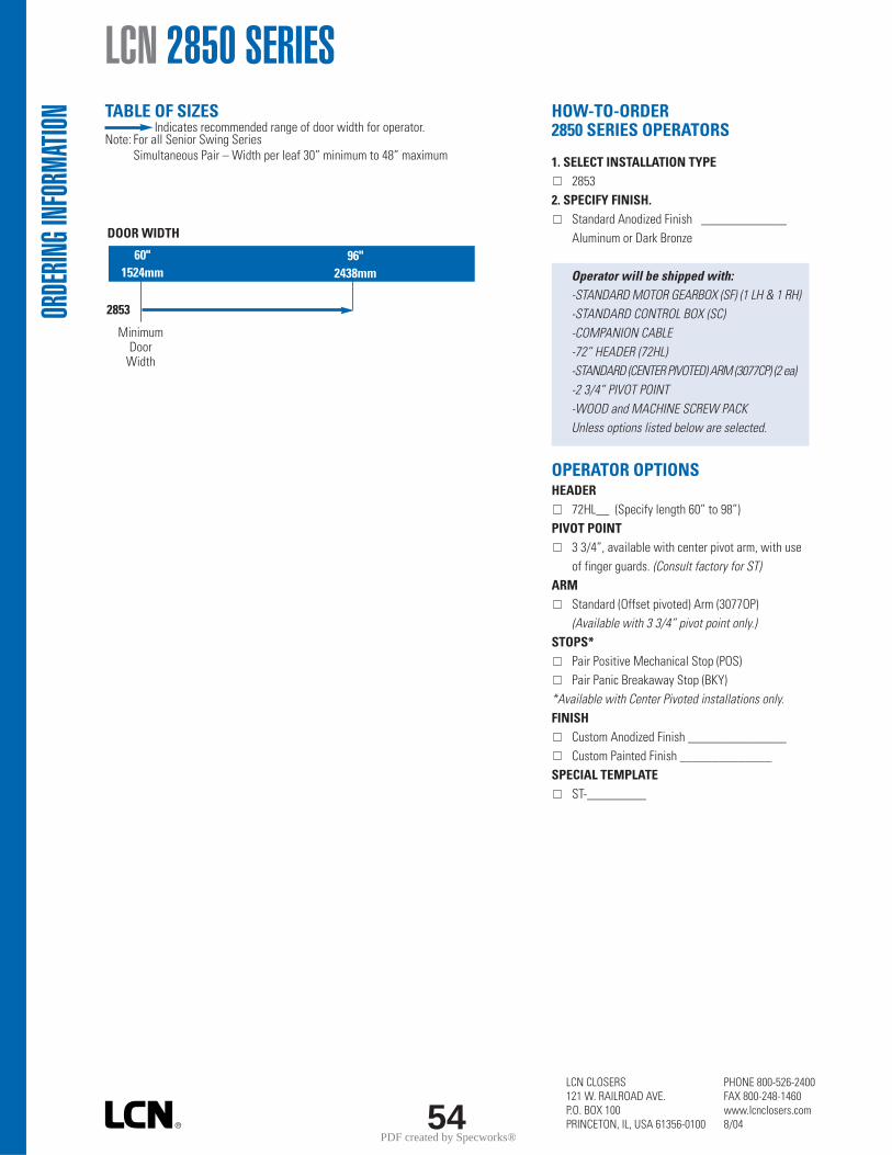
LCN CLOSERS121 W. RAILROAD AVE.P.O. BOX 100PRINCETON, IL, USA 61356-0100
PHONE 800-526-2400FAX 800-248-1460www.lcnclosers.com8/0454
TABLE OF SIZES Indicates recommended range of door width for operator.
Note: For all Senior Swing SeriesSimultaneous Pair – Width per leaf 30” minimum to 48” maximum
size
LCN 2850 SERIES
DOOR WIDTH
60"1524mm
96"2438mm
2853
MinimumDoor
Width
HOW-TO-ORDER2850 SERIES OPERATORS
1. SELECT INSTALLATION TYPE2853
2. SPECIFY FINISH.Standard Anodized Finish _____________Aluminum or Dark Bronze
Operator will be shipped with:-STANDARD MOTOR GEARBOX (SF) (1 LH & 1 RH)-STANDARD CONTROL BOX (SC)-COMPANION CABLE-72” HEADER (72HL)-STANDARD (CENTER PIVOTED) ARM (3077CP) (2 ea)-2 3/4” PIVOT POINT-WOOD and MACHINE SCREW PACKUnless options listed below are selected.
OPERATOR OPTIONSHEADER
72HL__ (Specify length 60” to 98”)PIVOT POINT
3 3/4”, available with center pivot arm, with useof finger guards. (Consult factory for ST)
ARMStandard (Offset pivoted) Arm (3077OP)(Available with 3 3/4” pivot point only.)
STOPS*Pair Positive Mechanical Stop (POS)Pair Panic Breakaway Stop (BKY)
*Available with Center Pivoted installations only.FINISH
Custom Anodized Finish _______________Custom Painted Finish ______________
SPECIAL TEMPLATEST-_________
ORDE
RING I
NFOR
MATIO
N
PDF created by Specworks®

22
410 Concealed Overhead Door Holders/Stops
410 Series Medium-DutyGlynn-Johnson offers the most complete line of overhead doorholders and stops, offering solutions for the most complex doorcontrol problems. The 410 series offers the industry’s widest variety of functions, base materials and finishes to fit all medium to light-duty applications.
The perfect combination of form and function, Glynn-Johnson 410 series holders and stops offer effective door control and a low-profile design. Each model is constructed so that the channel is encased in the door and the jamb bracket is mortised in theframe. When the door is open, the arm and jamb bracket are visible. Conversely, when the door is in the closed position, theentire holder is completely concealed.
These versatile models can be used with most surface-applied door closers. The provided templates allow for variable mountingpositions, ranging from 85º to 110º of opening. These templates aredesigned for installation in almost all types of doors, includingdoors with conventional butt-type hinges or specialty hinges.
Four Models:• 410H Series Hold-Open • 410S Series Stop-Only • 410F Series Friction Hold-Open • 410SE Series Special Stop-Only
Five Sizes:• Simple• Standardized• Each model is available in five sizes
One Option:• SOC—Pin-in-Socket Security Screw Package
Unmatched Convenience:• Non-Handed• Improved Compatibility with Door Closers• Single/Double-Acting Doors• Interior Applications• Durable• Easy to Install• Improved Corrosion Resistance
Materials and Finishes:All models are available in 300 series Stainless Steel, Brass andSteel substrates. The broadest range of finishes in the industry isprovided to complement any design.
Finishes DescriptionUS3 Polished BrassUS4 Satin BrassUS10 Satin BronzeUS10B Oil Rubbed BronzeUS32 Polished Stainless SteelUS32D Satin Stainless SteelSP4 Powder Coast BrassSP10 Powder Coat BronzeSP28 Powder Coat AluminumSP313 Powder Coat Dark BronzeSPBLK Powder Coat Black652 Chrome-like Coating
ModelsGlynn-Johnson 410 series holders and stops are designed for medium- to light-duty applications. They’re ideal for openings that are subject to normal activity, providing protection for the door, frame, hinges and surrounding walls or obstructions.
All models incorporate the popular channel/slide-arm design andoffset jamb brackets. This improved design allows for simple fieldmodification of functions, should user requirements change.
410H Series Hold-Open (Suffix H) Hold-Open models provide a convenient method of holding the door open at a predetermined position for short or long periods of time, permitting an unobstructed traffic flow. The Hold-Open tension can be adjusted using an allen wrenchthrough the end of the slider located in the channel mounted inthe top of the door.
These models feature a rugged, automatic Hold-Open mechanismactivated when the door is opened to a preset angle. Each modelmeets the 250,000 test cycles required for Grade 1 classification.The Hold-Open feature is not selectable, so the door is always held open.
410S Series Stop-Only (Suffix S) When the Hold-Open function is not a requirement,theStop-Only function provides an effective method of door control.The Stop-Only model may be used on fire doors.
PDF created by Specworks®
23
410F Series Friction Hold-Open (Suffix F) Friction Hold-Open models are ideal for patient roomdoors, wardrobe and closet doors, or similar applications wheremultiple Hold-Open positions are desired. The friction tension can be adjusted using a allen wrench on the slider located in thechannel mounted at the top of the door.
410SE Series Special Stop-Only (Suffix SE) When Stop-Only models are used in conjunction withsingle-point, Hold-Open electronic door closers, the Stop-Onlyfunction may be ordered less the shock-absorbing mechanism. Used as an auxiliary stop, these optional models prolong the life of the closer. The stop location is adjusted using an allen wrenchon the stop block located in the channel.
Note: Caution should be taken when using this option in other applications, as the elimination of the shock-absorbing spring can put added stress on the door and frame.
Application InformationUL ClassificationThe 410 series Stop-Only models are classified by UnderwritersLaboratories (UL) as Miscellaneous Fire Door Accessories. Thisclassification applies to use on either Hollow Metal Fire Doors orWood Fire Doors. Where Wood Door manufacturer’s listing allowsfor the cutout required for installation, concealed overhead stopsmay be used on those wood fire doors. These units may be used ondoors of any rating. As a reminder, the Miscellaneous Fire DoorAccessories (GVUX) section is defined by UL as: “Miscellaneousfire door accessories are intended in the individual Listings. Theaccessories have been investigated to determine that when installedin accordance with the manufacturer’s instructions, the accessoriesdo not adversely affect the fire rating of the fire door and/or firedoor frames.”
Dead-Stop Templating:Dead-Stop Templating is recommended for applications where awall or similar obstruction is in place at an opening angle of 110ºor less (i.e., doors that open back-to-back). Dead-Stop Templatingcan be applied to Hold-Open, Stop-Only and Friction models. The Dead-Stop position is the point at which the shock-absorbingspring is fully compressed. Therefore, when Dead-Stop Templatingis used, the initial degree of opening will be 5º to 7º less thanthe Dead-Stop opening.
Example: If the holder is templated to a 100º dead stop, the door will hold openat an angle between 93º and 95º but no further than 100º.
Note: Do not use dead-stop templating on the 410SE Series since there is noshock-absorbing spring.
Environmental Considerations:Environmental factors should always be considered when specifying overhead holders and stops. Doors that are positioned on a building’s exterior or subject to corrosive conditions should be equipped with a holder constructed primarily of stainless steel,brass or bronze materials. For interior applications, steel isacceptable, though brass and bronze substrates generally provide a more attractive architectural-grade finish.
Heavy-Use Applications:A heavy-duty holder or stop should be considered when doorsand frames are subject to heavy, frequent use. Also, heavy-dutyunits should be considered on exterior doors subject to wind.
OptionsSuffix SOC (Pin-in-Socket Security Screw Package):A screw package with pin-in-socket screws for mounting the jambbracket to the frame is provided instead of the standard screw package.
PDF created by Specworks®
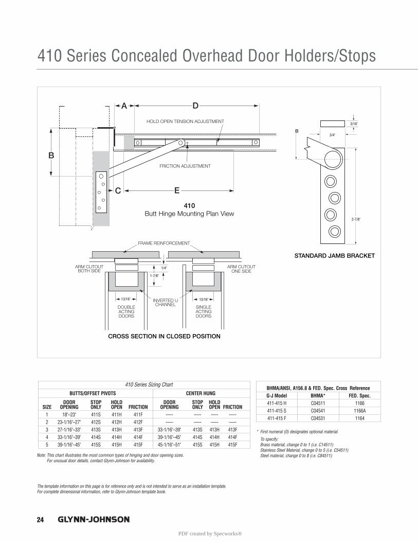
410 Series Concealed Overhead Door Holders/Stops
24
3/16"
3/4"
2-7/8"
13/16"13/16"
1-7/8"
1/4"
BUTTS/OFFSET PIVOTS CENTER HUNG
DOOR STOP HOLD DOOR STOP HOLDSIZE OPENING ONLY OPEN FRICTION OPENING ONLY OPEN FRICTION
1 18"–23" 411S 411H 411F ----- ----- ----- -----2 23-1/16"–27" 412S 412H 412F ----- ----- ----- -----3 27-1/16"–33" 413S 413H 413F 33-1/16"–39" 413S 413H 413F 4 33-1/16"–39" 414S 414H 414F 39-1/16"–45" 414S 414H 414F5 39-1/16"–45" 415S 415H 415F 45-1/16"–51" 415S 415H 415F
410 Series Sizing Chart
* First numeral (0) designates optional material.
To specify: Brass material, change 0 to 1 (i.e. C14511)Stainless Steel Material, change 0 to 5 (i.e. C54511)Steel material, change 0 to 8 (i.e. C84511)Note: This chart illustrates the most common types of hinging and door opening sizes.
For unusual door details, contact Glynn-Johnson for availability.
The template information on this page is for reference only and is not intended to serve as an installation template. For complete dimensional information, refer to Glynn-Johnson template book.
BHMA/ANSI, A156.8 & FED. Spec. Cross ReferenceG-J Model BHMA* FED. Spec.411-415 H C04511 1166411-415 S C04541 1166A411-415 F C04531 1164
PDF created by Specworks®
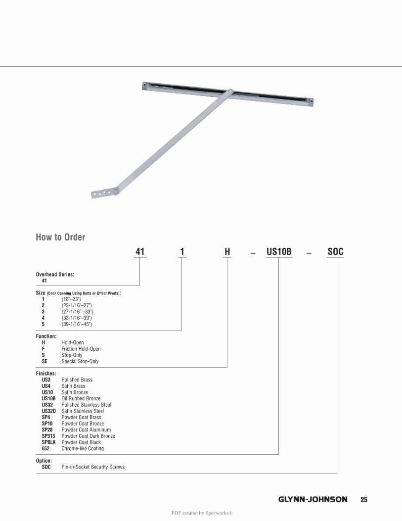
25
Overhead Series:41
Size (Door Opening Using Butts or Offset Pivots):1 (18"–23")2 (23-1/16"–27")3 (27-1/16" –33")4 (33-1/16"–39")5 (39-1/16"–45")
Function:H Hold-OpenF Friction Hold-OpenS Stop-OnlySE Special Stop-Only
Finishes:US3 Polished BrassUS4 Satin BrassUS10 Satin BronzeUS10B Oil Rubbed BronzeUS32 Polished Stainless SteelUS32D Satin Stainless SteelSP4 Powder Coat BrassSP10 Powder Coat BronzeSP28 Powder Coat AluminumSP313 Powder Coat Dark BronzeSPBLK Powder Coat Black652 Chrome-like Coating
Option:SOC Pin-in-Socket Security Screws
___ __ __ – ______ – ____
How to Order
41 1 H US10B SOC
PDF created by Specworks®
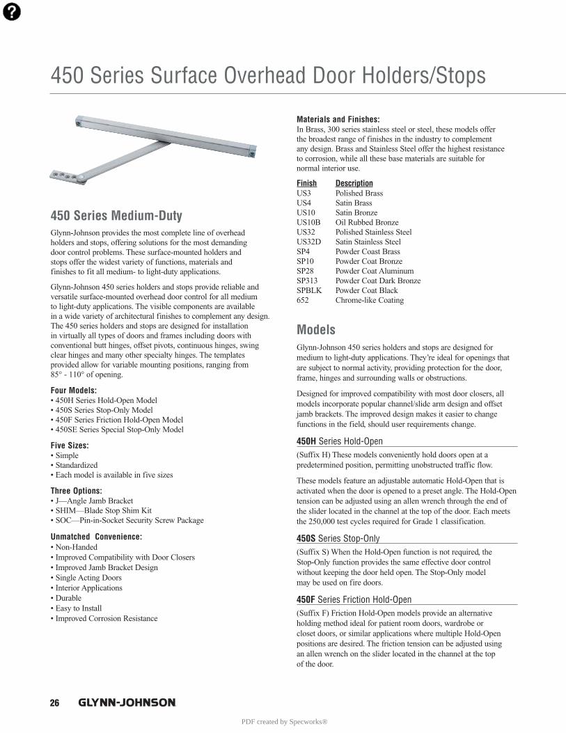
26
450 Series Surface Overhead Door Holders/Stops
Materials and Finishes:In Brass, 300 series stainless steel or steel, these models offer the broadest range of finishes in the industry to complement any design. Brass and Stainless Steel offer the highest resistance to corrosion, while all these base materials are suitable for normal interior use.
Finish DescriptionUS3 Polished BrassUS4 Satin BrassUS10 Satin BronzeUS10B Oil Rubbed BronzeUS32 Polished Stainless SteelUS32D Satin Stainless SteelSP4 Powder Coast BrassSP10 Powder Coat BronzeSP28 Powder Coat AluminumSP313 Powder Coat Dark BronzeSPBLK Powder Coat Black652 Chrome-like Coating
ModelsGlynn-Johnson 450 series holders and stops are designed for medium to light-duty applications. They’re ideal for openings thatare subject to normal activity, providing protection for the door,frame, hinges and surrounding walls or obstructions.
Designed for improved compatibility with most door closers, allmodels incorporate popular channel/slide arm design and offsetjamb brackets. The improved design makes it easier to change functions in the field, should user requirements change.
450H Series Hold-Open (Suffix H) These models conveniently hold doors open at a predetermined position, permitting unobstructed traffic flow.
These models feature an adjustable automatic Hold-Open that isactivated when the door is opened to a preset angle. The Hold-Opentension can be adjusted using an allen wrench through the end ofthe slider located in the channel at the top of the door. Each meetsthe 250,000 test cycles required for Grade 1 classification.
450S Series Stop-Only (Suffix S) When the Hold-Open function is not required, the Stop-Only function provides the same effective door control without keeping the door held open. The Stop-Only model may be used on fire doors.
450F Series Friction Hold-Open (Suffix F) Friction Hold-Open models provide an alternative holding method ideal for patient room doors, wardrobe or closet doors, or similar applications where multiple Hold-Openpositions are desired. The friction tension can be adjusted using an allen wrench on the slider located in the channel at the top of the door.
450 Series Medium-DutyGlynn-Johnson provides the most complete line of overhead holders and stops, offering solutions for the most demanding door control problems. These surface-mounted holders and stops offer the widest variety of functions, materials and finishes to fit all medium- to light-duty applications.
Glynn-Johnson 450 series holders and stops provide reliable andversatile surface-mounted overhead door control for all medium to light-duty applications. The visible components are available in a wide variety of architectural finishes to complement any design.The 450 series holders and stops are designed for installation in virtually all types of doors and frames including doors with conventional butt hinges, offset pivots, continuous hinges, swingclear hinges and many other specialty hinges. The templates provided allow for variable mounting positions, ranging from 85° - 110° of opening.
Four Models:• 450H Series Hold-Open Model• 450S Series Stop-Only Model• 450F Series Friction Hold-Open Model• 450SE Series Special Stop-Only Model
Five Sizes:• Simple• Standardized• Each model is available in five sizes
Three Options:• J—Angle Jamb Bracket• SHIM—Blade Stop Shim Kit• SOC—Pin-in-Socket Security Screw Package
Unmatched Convenience:• Non-Handed• Improved Compatibility with Door Closers• Improved Jamb Bracket Design• Single Acting Doors• Interior Applications• Durable• Easy to Install• Improved Corrosion Resistance
PDF created by Specworks®

27
450SE Series Special Stop-Only (Suffix SE) When Stop-Only models are used in conjunction with single point Hold-Open electronic door closers, the functionmay be ordered without the shock absorbing mechanism. Used as an auxiliary stop with these closers, they will prolong the life of the closer. The stop location is adjusted using an allenwrench on the stop block located in the channel.
Note: Caution should be taken when using this option in other applications, as the elimination of the shock-absorbing spring can put added stress on the door and frame.
Application InformationCloser ApplicationsGlynn-Johnson 450 series models require minimal door and framepreparation. They may be used in conjunction with most surface-applied door closers. In some cases, optional drop brackets mayneed to be mounted on the closers. These brackets are availablefrom the closer manufacturer.
UL ClassificationThe 450 series Stop-Only models are classified by UnderwritersLaboratories (UL) as Miscellaneous Fire Door Accessories. Thisclassification applies to use on either Hollow Metal Fire Doors orWood Fire Doors. These units may be used on doors of any rating.As a reminder, the Miscellaneous Fire Door Accessories (GVUX)section is defined by UL as: “Miscellaneous fire door accessoriesare intended in the individual Listings. The accessories have beeninvestigated to determine that when installed in accordance with themanufacturer’s instructions, the accessories do not adversely affectthe fire rating of the fire door and/or fire door frames.”
Dead-Stop Templating: For situations where a wall or similar obstruction is in place at an opening angle of 110° or less (e.g. doors that open back-to-back),dead stop templating should be used. This includes all Hold-Open,Friction and Stop-Only models, except when the "SE" option is used. The Dead Stop position is reached when the shock-absorbingspring is fully compressed, allowing an initial degree of opening of5º to 7º less than the Dead Stop opening.
Example: If the holder is templated for 100° Dead Stop, the door will holdopen somewhere between 93° to 95°, and no further than 100°.
Note: Do not use dead-stop templating on the 450SE Series since there is noshock-absorbing spring.
Environmental Conditions: To assure a long operating life for holders and stops, consider the environment where they will be used. Doors that open to the exterior of a building or are subject to corrosive conditionsshould have a holder constructed primarily of stainless steel, brass or bronze materials. For interior doors, steel material may be acceptable, although brass and bronze substrates will provide a more attractive architectural grade finish.
Heavy-Use Applications: Where doors and frames are subject to heavy use and abuse, a heavy-duty holder or stop should be considered. Also heavy-dutyunits should be considered on exterior doors subject to wind.
OptionsSuffix J (Angle Jamb Bracket):An additional option on the 450 Series is the Angle Jamb Bracketfor hinge-side or flush transom mounting. The angle jamb bracketaffixes to the standard jamb bracket. If ordered with the overheadadd suffix J. If needed separately order 450J-Finish.
Suffix SHIM (Blade Stop Shims):Shim kits are available in 3 sizes:450 SHIM1 is a 3/16" Shim Kit450 SHIM2 is a 3/8" Shim Kit450 SHIM3 is a 9/16" Shim Kit
If ordered with overhead, add suffix SHIM (1, 2 or 3). If needed separately order 450SHIM (1, 2 or 3)–Finish.
Suffix SOC (Pin-in-Socket Security Screw Package):A screw package with pin-in-socket screws for mounting the channelto the door and the jamb bracket to the frame is provided instead ofthe standard screw package.
PDF created by Specworks®

28
450 Series Surface Overhead Door Holders/Stops
The template information on this page is for reference only and is not intended to serve as an installation template. For complete dimensional information, refer to Glynn-Johnson template book.
1-5/16"7/8"
3/16"
3/16"1-1/4"
1-1/4"2-1/4"
2-7/8"
3/16"
3/4"
BUTTS/OFFSET PIVOTS CENTER HUNG
DOOR STOP HOLD DOOR STOP HOLDSIZE OPENING ONLY OPEN FRICTION OPENING ONLY OPEN FRICTION
1 18"–23" 451S 451H 451F 23-1/16"–27" 451S 451H 451F2 23-1/16"–27" 452S 452H 452F 27-1/16"–33" 452S 452H 452F3 27-1/16"–33" 453S 453H 453F 33-1/16"–39" 453S 453H 453F 4 33-1/16"–39" 454S 454H 454F 39-1/16"–45" 454S 454H 454F5 39-1/16"–45" 455S 455H 455F 45-1/16"–51" 455S 455H 455F
450 Series Sizing Chart
* First numeral (0) designates optional material.
To specify: Brass/bronze material, change 0 to 1 (e.e. C15511)Stainless Steel Material, change 0 to 5 (i.e. C55511)Steel material, change 0 to 8 (i.e. C85511)Note: This chart illustrates the most common types of hinging and door opening sizes.
For unusual door details, contact Glynn-Johnson for availability.
BHMA/ANSI, A156.8 & FED. Spec. Cross ReferenceG-J Model BHMA* FED. Spec.451-455 H C05511 1166451-455 S C05541 1166A451-455 F C05531 1164
PDF created by Specworks®
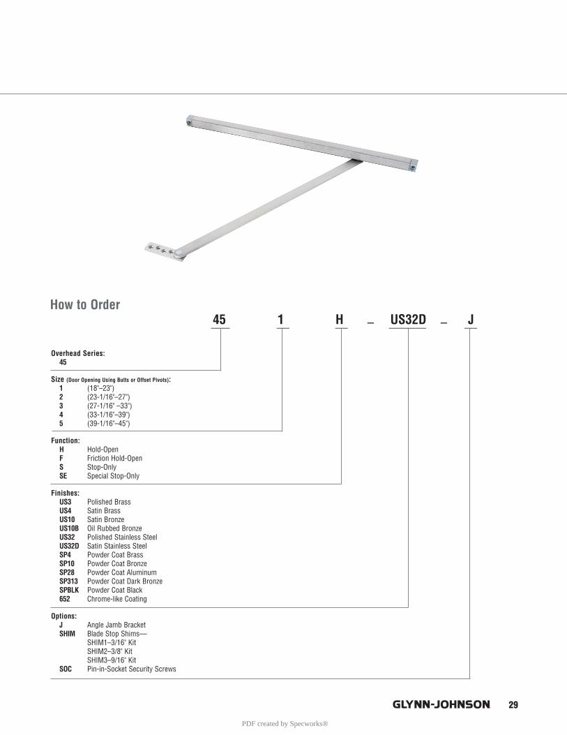
Overhead Series:45
Size (Door Opening Using Butts or Offset Pivots):1 (18"–23")2 (23-1/16"–27")3 (27-1/16" –33")4 (33-1/16"–39")5 (39-1/16"–45")
Function:H Hold-OpenF Friction Hold-OpenS Stop-OnlySE Special Stop-Only
Finishes:US3 Polished BrassUS4 Satin BrassUS10 Satin BronzeUS10B Oil Rubbed BronzeUS32 Polished Stainless SteelUS32D Satin Stainless SteelSP4 Powder Coat BrassSP10 Powder Coat BronzeSP28 Powder Coat AluminumSP313 Powder Coat Dark BronzeSPBLK Powder Coat Black652 Chrome-like Coating
Options: J Angle Jamb BracketSHIM Blade Stop Shims—
SHIM1–3/16" KitSHIM2–3/8" KitSHIM3–9/16" Kit
SOC Pin-in-Socket Security Screws
29
How to Order45 1 H US32D J___ __ __ – ______ – __
PDF created by Specworks®
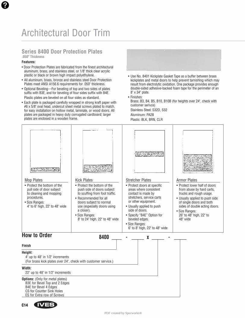
C14
Architectural Door Trim
Mop Plates• Protect the bottom of the
pull side of door subject to cleaning and mopping procedures.
• Size Ranges:4" to 6" high, 22" to 48" wide
Kick Plates• Protect the bottom of the
push side of doors subject to scuffing from foot traffic.
• Recommended for all doors subject to normaluse (especially doors using a closer).
• Size Ranges:8" to 24" high, 22" to 48" wide
Stretcher Plates• Protect doors at specific
areas where consistent contact is made by stretchers, service carts or other equipment.
• Usually applied to push side of doors.
• Specify “B4E” Option forbeveled edges.
• Size Ranges:6" to 8" high, 22" to 48" wide
Armor Plates• Protect lower half of doors
from abuse by hard carts,trucks and rough usage.
• Usually applied to push sideof single doors and bothsides of double acting doors.
• Size Ranges:26" to 48" high, 22" to 48" wide
Series 8400 Door Protection Plates.050" ThicknessFeatures:• Door Protection Plates are fabricated from the finest architectural
aluminum, brass, and stainless steel, or 1/8" thick clear acrylicplastic or black or brown high impact polyethylene.
• All aluminum, brass, bronze and stainless steel Door ProtectionPlates meet ANSI A156.6 requirements for .050" thickness.
• Optional Beveling—For beveling of top and two sides of plates suffix with B3E, and for beveling of four sides suffix with B4E. Plastic plates are beveled on all four sides as standard.
• Each plate is packaged carefully wrapped in strong kraft paper with#6 x 5/8" oval head, undercut sheet metal screws plated to match,for easy installation on hollow metal, laminate, or wood doors. Allplates are packaged in heavy duty corrugated cardboard; largerplates are enclosed in a wooden frame.
• Use No. 8401 Kickplate Gasket Tape as a buffer between brasskickplates and metal doors to help prevent tarnishing which mayresult from electrolytic oxidation. One package provides enoughdouble-sided adhesive-backed foam tape for the perimeter of an 8" x 34" plate.
• Finishes:Brass: B3, B4, B5, B10, B10B (for heights over 24", check withcustomer serivce)Stainless Steel: S32D, S32Aluminum: PA28Plastic: BLK, BRN, CLR
How to Order 8400 ____ - _____ x _____ - _____Finish
Height: 4" up to 48" in 1/2" increments (For brass kick plates over 24", check with customer service.)
Width:22" up to 48" in 1/2" increments
Options: (Only for metal plates)B3E for Bevel Top and 2 EdgesB4E for Bevel 4 EdgesCS for Counter Sink HolesES for Extra row of Screws
PDF created by Specworks®
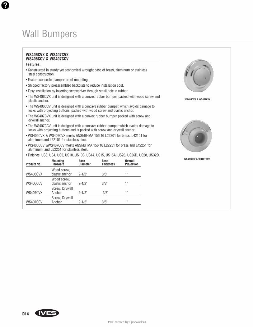
Wall Bumpers
D14
WS406CVX & WS407CVXWS406CCV & WS407CCVFeatures:• Constructed in sturdy yet economical wrought base of brass, aluminum or stainless
steel construction.• Feature concealed tamper-proof mounting.• Shipped factory preassembled backplate to reduce installation cost.• Easy installation by inserting screwdriver through small hole in rubber.• The WS406CVX unit is designed with a convex rubber bumper, packed with wood screw and
plastic anchor.• The WS406CCV unit is designed with a concave rubber bumper, which avoids damage to
locks with projecting buttons, packed with wood screw and plastic anchor.• The WS407CVX unit is designed with a convex rubber bumper packed with screw and
drywall anchor.• The WS407CCV unit is designed with a concave rubber bumper which avoids damage to
locks with projecting buttons and is packed with screw and drywall anchor.• WS406CVX & WS407CVX meets ANSI/BHMA 156.16 L22201 for brass, L42101 for
aluminum and L52101 for stainless steel.• WS406CCV &WS407CCV meets ANSI/BHMA 156.16 L22251 for brass and L42251 for
aluminum, and L52251 for stainless steel.• Finishes: US3, US4, US5, US10, US10B, US14, US15, US15A, US26, US26D, US28, US32D.
Mounting Base Base OverallProduct No. Hardware Diameter Thickness Projection
Wood screw,WS406CVX plastic anchor 2-1/2" 3/8" 1"
Wood screw,WS406CCV plastic anchor 2-1/2" 3/8" 1"
Screw, DrywallWS407CVX Anchor 2-1/2" 3/8" 1"
Screw, DrywallWS407CCV Anchor 2-1/2" 3/8" 1"
WS406CVX & WS407CVX
WS406CCV & WS407CCV
PDF created by Specworks®

PDF created by Specworks®
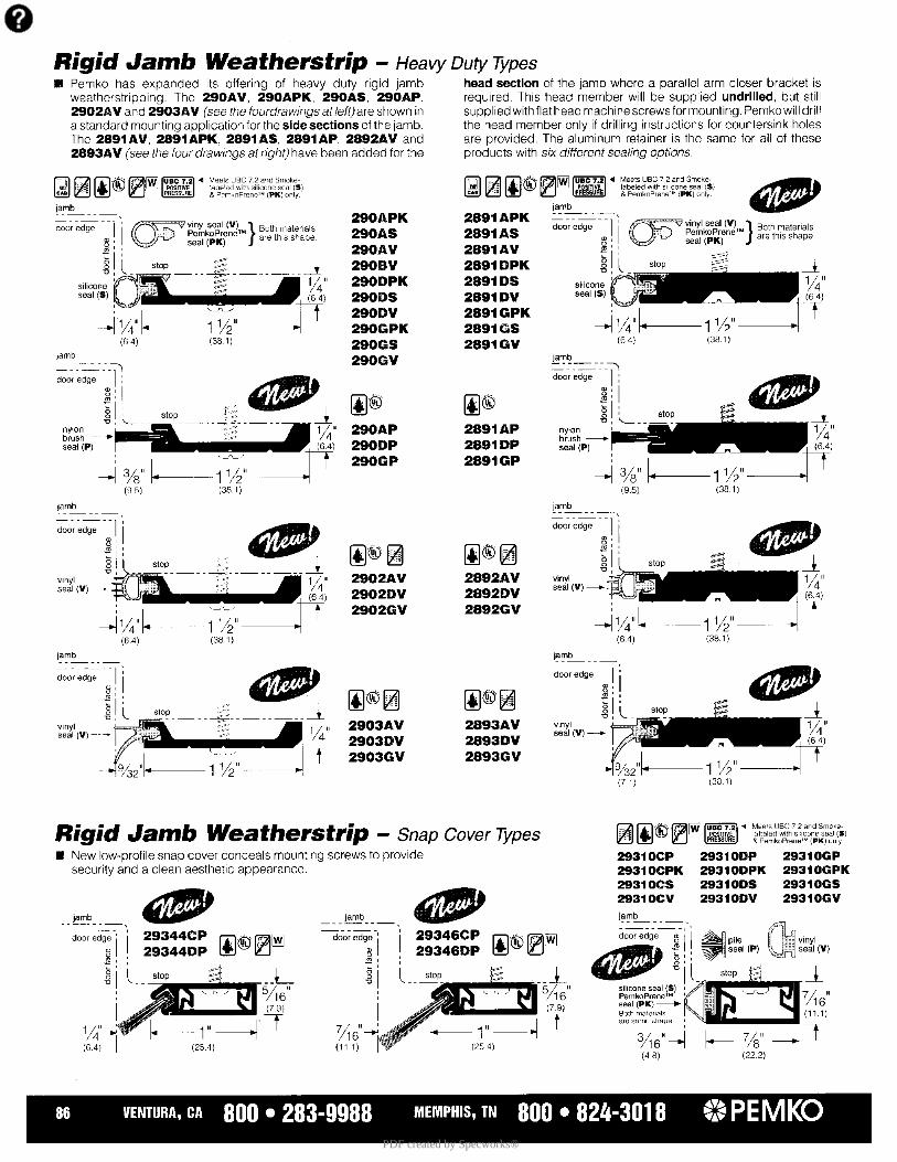
PDF created by Specworks®
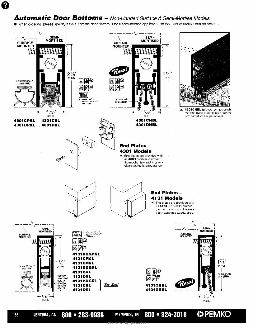
PDF created by Specworks®

PDF created by Specworks®
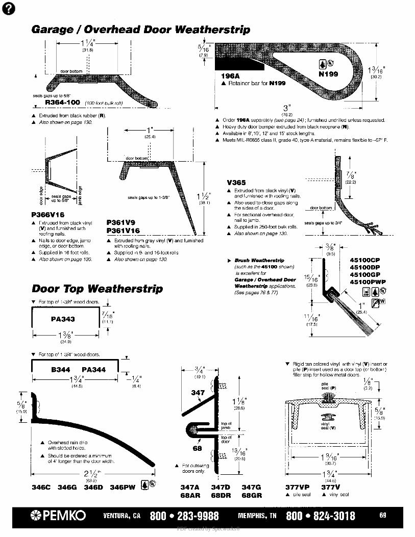
PDF created by Specworks®
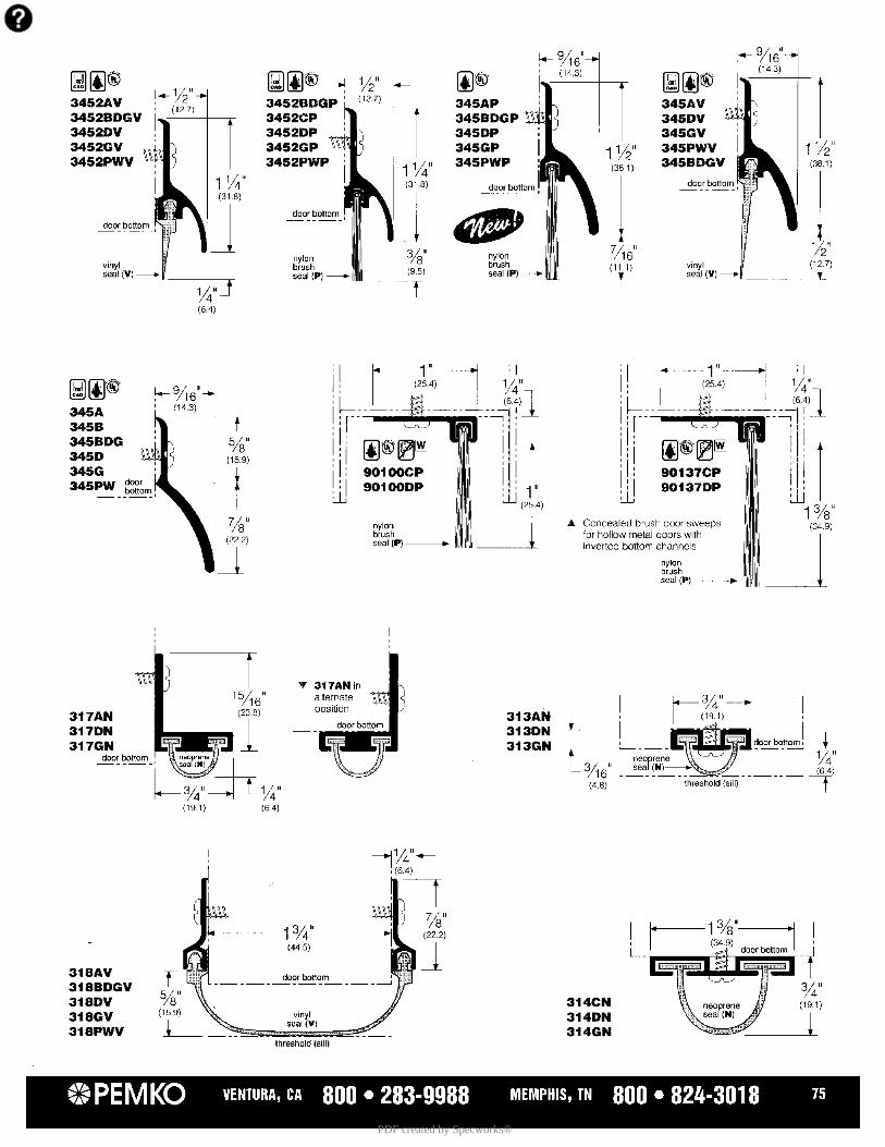
PDF created by Specworks®
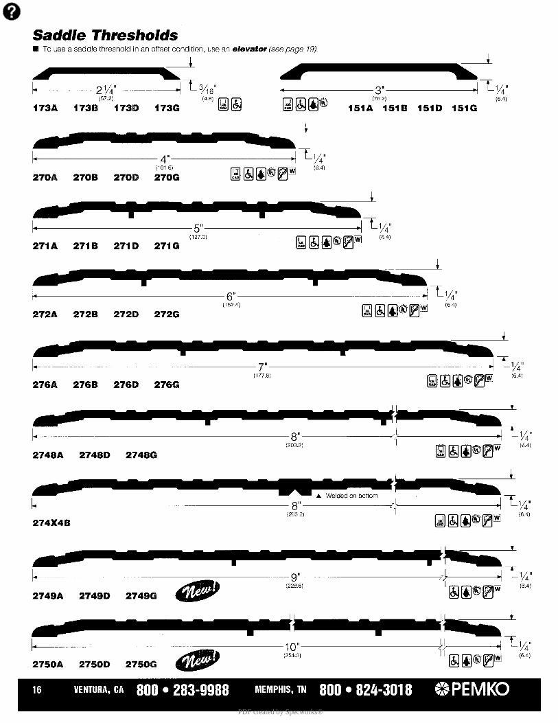
PDF created by Specworks®
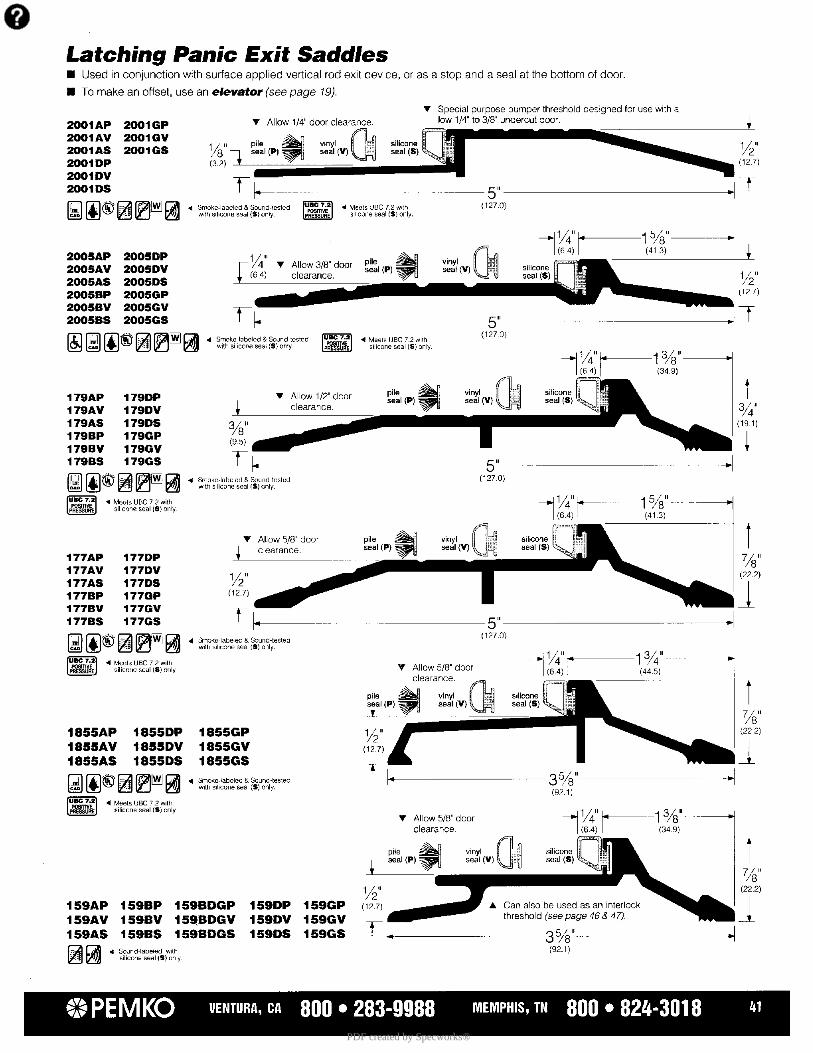
PDF created by Specworks®
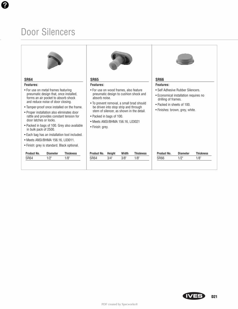
Door Silencers
SR64Features:• For use on metal frames featuring
pneumatic design that, once installed,forms an air pocket to absorb shock and reduce noise of door closing.
• Tamper-proof once installed on the frame.• Proper installation also eliminates door
rattle and provides constant tension fordoor latches or locks.
• Packed in bags of 100. Grey also availablein bulk pack of 2500.
• Each bag has an installation tool included.• Meets ANSI/BHMA 156.16, L03011.• Finish: grey is standard. Black optional.
SR65Features:• For use on wood frames, also feature
pneumatic design to cushion shock andabsorb noise.
• To prevent removal, a small brad shouldbe driven into stop strip and throughstem of silencer, as shown in the detail.
• Packed in bags of 100.• Meets ANSI/BHMA 156.16, L03021• Finish: grey.
SR66Features:• Self Adhesive Rubber Silencers.• Economical installation requires no
drilling of frames.• Packed in sheets of 100.• Finishes: brown, grey, white.
Product No. Diameter ThicknessSR64 1/2" 1/8"
Product No. Height Width ThicknessSR64 3/4" 3/8" 1/8"
Product No. Diameter ThicknessSR66 1/2" 1/8"
D21
PDF created by Specworks®
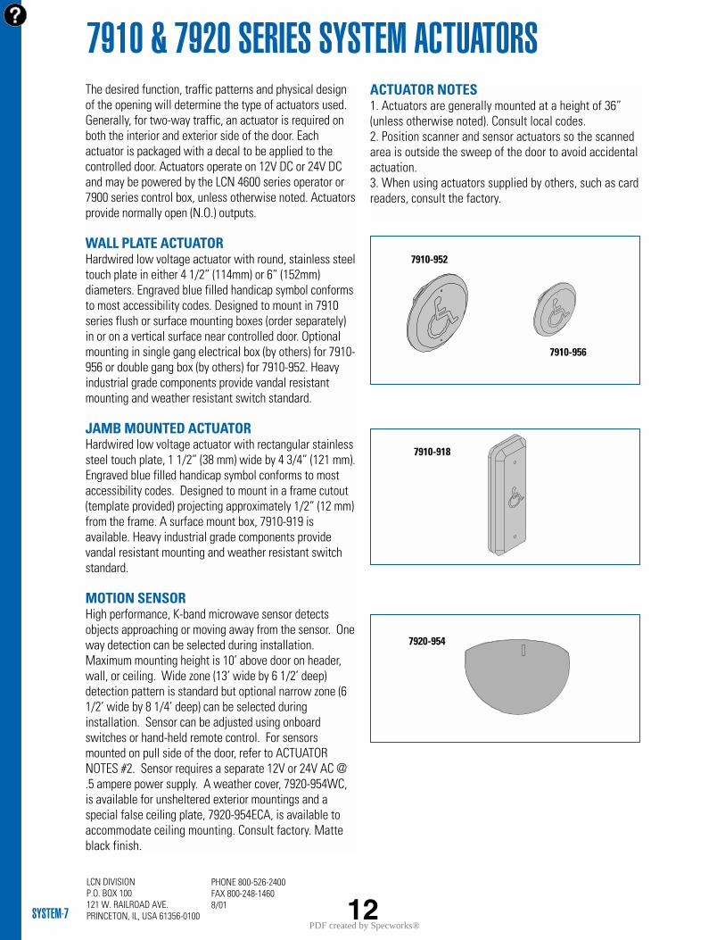
LCN DIVISIONP.O. BOX 100121 W. RAILROAD AVE.PRINCETON, IL, USA 61356-0100SYSTEM-7
PHONE 800-526-2400FAX 800-248-14608/01
7910 & 7920 SERIES SYSTEM ACTUATORSThe desired function, traffic patterns and physical designof the opening will determine the type of actuators used.Generally, for two-way traffic, an actuator is required onboth the interior and exterior side of the door. Eachactuator is packaged with a decal to be applied to thecontrolled door. Actuators operate on 12V DC or 24V DCand may be powered by the LCN 4600 series operator or7900 series control box, unless otherwise noted. Actuatorsprovide normally open (N.O.) outputs.
WALL PLATE ACTUATOR Hardwired low voltage actuator with round, stainless steeltouch plate in either 4 1/2” (114mm) or 6” (152mm)diameters. Engraved blue filled handicap symbol conformsto most accessibility codes. Designed to mount in 7910series flush or surface mounting boxes (order separately)in or on a vertical surface near controlled door. Optionalmounting in single gang electrical box (by others) for 7910-956 or double gang box (by others) for 7910-952. Heavyindustrial grade components provide vandal resistantmounting and weather resistant switch standard.
JAMB MOUNTED ACTUATORHardwired low voltage actuator with rectangular stainlesssteel touch plate, 1 1/2” (38 mm) wide by 4 3/4” (121 mm).Engraved blue filled handicap symbol conforms to mostaccessibility codes. Designed to mount in a frame cutout(template provided) projecting approximately 1/2” (12 mm)from the frame. A surface mount box, 7910-919 isavailable. Heavy industrial grade components providevandal resistant mounting and weather resistant switchstandard.
MOTION SENSORHigh performance, K-band microwave sensor detectsobjects approaching or moving away from the sensor. Oneway detection can be selected during installation.Maximum mounting height is 10’ above door on header,wall, or ceiling. Wide zone (13’ wide by 6 1/2’ deep)detection pattern is standard but optional narrow zone (61/2’ wide by 8 1/4’ deep) can be selected duringinstallation. Sensor can be adjusted using onboardswitches or hand-held remote control. For sensorsmounted on pull side of the door, refer to ACTUATORNOTES #2. Sensor requires a separate 12V or 24V AC @.5 ampere power supply. A weather cover, 7920-954WC,is available for unsheltered exterior mountings and aspecial false ceiling plate, 7920-954ECA, is available toaccommodate ceiling mounting. Consult factory. Matteblack finish.
ACTUATOR NOTES1. Actuators are generally mounted at a height of 36”(unless otherwise noted). Consult local codes.2. Position scanner and sensor actuators so the scannedarea is outside the sweep of the door to avoid accidentalactuation.3. When using actuators supplied by others, such as cardreaders, consult the factory.
12
7910-918
7910-956
7910-952
7920-954
PDF created by Specworks®
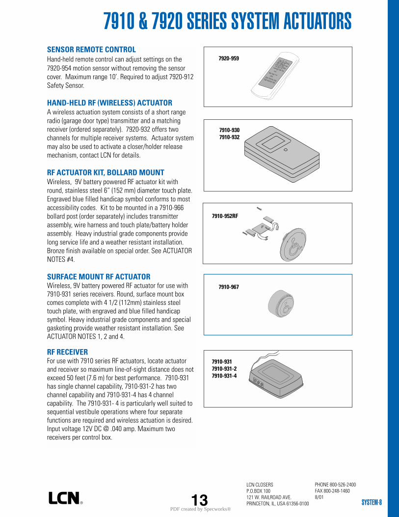
LCN CLOSERS P.O.BOX 100121 W. RAILROAD AVE.PRINCETON, IL, USA 61356-0100 SYSTEM-8
SENSOR REMOTE CONTROLHand-held remote control can adjust settings on the7920-954 motion sensor without removing the sensorcover. Maximum range 10’. Required to adjust 7920-912Safety Sensor.
HAND-HELD RF (WIRELESS) ACTUATORA wireless actuation system consists of a short rangeradio (garage door type) transmitter and a matchingreceiver (ordered separately). 7920-932 offers twochannels for multiple receiver systems. Actuator systemmay also be used to activate a closer/holder releasemechanism, contact LCN for details.
RF ACTUATOR KIT, BOLLARD MOUNT Wireless, 9V battery powered RF actuator kit withround, stainless steel 6” (152 mm) diameter touch plate.Engraved blue filled handicap symbol conforms to mostaccessibility codes. Kit to be mounted in a 7910-966bollard post (order separately) includes transmitterassembly, wire harness and touch plate/battery holderassembly. Heavy industrial grade components providelong service life and a weather resistant installation.Bronze finish available on special order. See ACTUATORNOTES #4.
SURFACE MOUNT RF ACTUATORWireless, 9V battery powered RF actuator for use with7910-931 series receivers. Round, surface mount boxcomes complete with 4 1/2 (112mm) stainless steeltouch plate, with engraved and blue filled handicapsymbol. Heavy industrial grade components and specialgasketing provide weather resistant installation. SeeACTUATOR NOTES 1, 2 and 4.
RF RECEIVERFor use with 7910 series RF actuators, locate actuatorand receiver so maximum line-of-sight distance does notexceed 50 feet (7.6 m) for best performance. 7910-931has single channel capability, 7910-931-2 has twochannel capability and 7910-931-4 has 4 channelcapability. The 7910-931- 4 is particularly well suited tosequential vestibule operations where four separatefunctions are required and wireless actuation is desired.Input voltage 12V DC @ .040 amp. Maximum tworeceivers per control box.
7910 & 7920 SERIES SYSTEM ACTUATORS7920-959
7910-9307910-932
7910-952RF
13
7910-967
7910-9317910-931-27910-931-4
PHONE 800-526-2400FAX 800-248-14608/01
PDF created by Specworks®
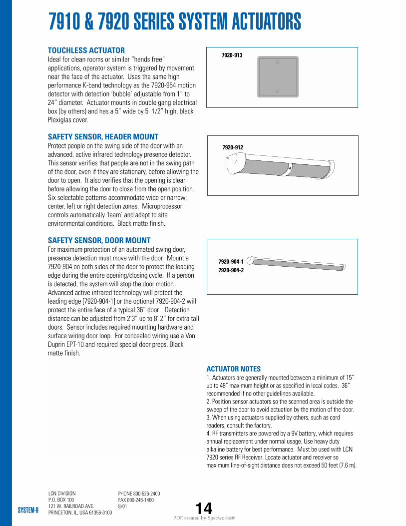
LCN DIVISIONP.O. BOX 100121 W. RAILROAD AVE.PRINCETON, IL, USA 61356-0100SYSTEM-9
PHONE 800-526-2400FAX 800-248-14608/01
7910 & 7920 SERIES SYSTEM ACTUATORSTOUCHLESS ACTUATOR Ideal for clean rooms or similar “hands free”applications, operator system is triggered by movementnear the face of the actuator. Uses the same highperformance K-band technology as the 7920-954 motiondetector with detection ‘bubble’ adjustable from 1” to24” diameter. Actuator mounts in double gang electricalbox (by others) and has a 5” wide by 5 1/2” high, blackPlexiglas cover.
SAFETY SENSOR, HEADER MOUNT Protect people on the swing side of the door with anadvanced, active infrared technology presence detector.This sensor verifies that people are not in the swing pathof the door, even if they are stationary, before allowing thedoor to open. It also verifies that the opening is clearbefore allowing the door to close from the open position.Six selectable patterns accommodate wide or narrow;center, left or right detection zones. Microprocessorcontrols automatically ‘learn’ and adapt to siteenvironmental conditions. Black matte finish.
SAFETY SENSOR, DOOR MOUNTFor maximum protection of an automated swing door,presence detection must move with the door. Mount a7920-904 on both sides of the door to protect the leadingedge during the entire opening/closing cycle. If a personis detected, the system will stop the door motion.Advanced active infrared technology will protect theleading edge [7920-904-1] or the optional 7920-904-2 willprotect the entire face of a typical 36” door. Detectiondistance can be adjusted from 2’3” up to 8’ 2” for extra talldoors. Sensor includes required mounting hardware andsurface wiring door loop. For concealed wiring use a VonDuprin EPT-10 and required special door preps. Blackmatte finish.
7920-912
7920-913
7920-904-17920-904-2
14
ACTUATOR NOTES1. Actuators are generally mounted between a minimum of 15”up to 48” maximum height or as specified in local codes. 36”recommended if no other guidelines available.2. Position sensor actuators so the scanned area is outside thesweep of the door to avoid actuation by the motion of the door.3. When using actuators supplied by others, such as cardreaders, consult the factory.4. RF transmitters are powered by a 9V battery, which requiresannual replacement under normal usage. Use heavy dutyalkaline battery for best performance. Must be used with LCN7920 series RF Receiver. Locate actuator and receiver somaximum line-of-sight distance does not exceed 50 feet (7.6 m).
PDF created by Specworks®
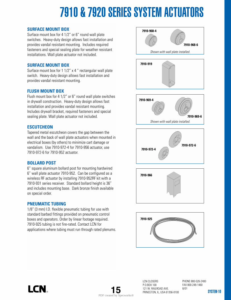
LCN CLOSERS P.O.BOX 100121 W. RAILROAD AVE.PRINCETON, IL, USA 61356-0100 SYSTEM-10
SURFACE MOUNT BOXSurface mount box for 4 1/2” or 6” round wall plateswitches. Heavy-duty design allows fast installation andprovides vandal resistant mounting. Includes requiredfasteners and special sealing plate for weather resistantinstallations. Wall plate actuator not included.
SURFACE MOUNT BOX Surface mount box for 1 1/2” x 4 ” rectangular wall plateswitch. Heavy-duty design allows fast installation andprovides vandal resistant mounting.
FLUSH MOUNT BOXFlush mount box for 4 1/2” or 6” round wall plate switchesin drywall construction. Heavy-duty design allows fastinstallation and provides vandal resistant mounting.Includes drywall bracket, required fasteners and specialsealing plate. Wall plate actuator not included.
ESCUTCHEON Tapered metal escutcheon covers the gap between thewall and the back of wall plate actuators when mounted inelectrical boxes (by others) to minimize cart damage orvandalism. Use 7910-972-4 for 7910-956 actuator, use7910-972-6 for 7910-952 actuator.
BOLLARD POST6” square aluminum bollard post for mounting hardwired6” wall plate actuator 7910-952. Can be configured as awireless RF actuator by installing 7910-952RF kit with a7910-931 series receiver. Standard bollard height is 36”and includes mounting base. Dark bronze finish availableon special order.
PNEUMATIC TUBING1/8” (3 mm) I.D. flexible pneumatic tubing for use withstandard barbed fittings provided on pneumatic controlboxes and operators. Order by linear footage required.7910-925 tubing is not fire-rated. Contact LCN forapplications where tubing must run through rated plenums.
15
7910 & 7920 SERIES SYSTEM ACTUATORS7910-968-4
7910-968-6
7910-919
7910-969-4
7910-969-6
7910-972-47910-972-6
7910-966
7910-925
Shown with wall plate installed.
Shown with wall plate installed.
PHONE 800-526-2400FAX 800-248-14608/01
PDF created by Specworks®
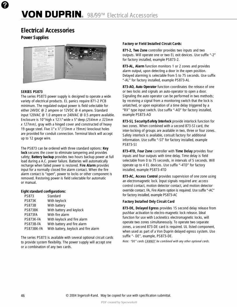
46 © 2004 Ingersoll-Rand. May be copied for use with specification submittal.
98/99™ Electrical Accessories
Power Supplies
SERIES PS873The series PS873 power supply is designed to operate a widevariety of electrical products. EL panics require 871-2 PCB minimum. The regulated output power is field selectable foreither 24VDC @ 2 ampere or 12VDC @ 4 ampere. Standardinput 120VAC @ 1.0 ampere or 240VAC @ 0.5 ampere available.Enclosure is 10" high x 12 1⁄2" wide x 5" deep (254mm x 323mmx 127mm), gray with a hinged cover and constructed of heavy19 gauge steel. Five 1⁄2" x 3⁄4" (13mm x 19mm) knockout holesare provided for conduit connection. Terminal block will accept up to 12 gauge wire.
The PS873 can be ordered with three standard options: Keylock secures the cover to eliminate tampering and providessafety; Battery backup provides two hours backup power at fullload during a A.C. power failure. Batteries will automaticallyrecharge when failed power is restored. Fire Alarm providesinput for a normally closed fire alarm contact. When the firealarm contact is “open”, power to locks or other component isremoved. Restoring power is field selectable for automatic or manual.
Eight standard configurations:PS873 StandardPS873K With keylockPS873B With batteryPS873BK With battery and keylockPS873FA With fire alarmPS873K-FA With keylock and fire alarmPS873B-FA With battery and fire alarmPS873BK-FA With battery, keylock and fire alarm
The series PS873 is available with several optional circuit cardsto provide system flexibility. The power supply will accept oneor a combination of any two cards.
Factory or Field Installed Circuit Cards:
871-2, Two Zone controller provides two inputs and twooutputs. Will operate one or two EL exit devices. Use suffix “-2”for factory installed, example PS873-2.
873-AL, Alarm function monitors 1 or 2 zones and providesalarm output, upon detecting a door in the open position.Delayed alarming is selectable from 5 to 75 seconds. Use suffix“-AL” for factory installed, example PS873-AL
873-AO, Auto Operator function coordinates the release of oneor two locks and signals an auto-operator to open a door.Signaling the auto operator can be performed in two methods;by receiving a signal from a monitoring switch that the lock isunlatched, or upon expiration of a time delay triggered by a“RX” type input switch. Use suffix “-AO” for factory installed,example PS873-AO
873-SI, Security/Safety Interlock provide interlock function fortwo zones. When combined with a second 873-SI card, theinter-locking of groups are available in two, three or four zones.Safety interlock is available, consult factory for additional information. Use suffix “-SI” for factory installed, examplePS873-SI
873-4TD, Four Zone controller with Time Delay provides fourinputs and four outputs with time delay. Time delay is fieldselectable from 0 to 75 seconds, in intervals of 5 seconds. Willoperate up to 4 EL devices. Use suffix “-4TD” for factoryinstalled, example PS873-4TD
873-AC, Access Control provides supervision of one zone usingan electromagnetic lock. Input signals required are: access control contact, motion detector contact, and motion detectoroverride contact. FA, Fire Alarm option is required. Use suffix “-AC”for factory installed, example PS873-AC
Factory Installed Only Circuit Card
873-DE, Delayed Egress provides 15 second delay release frompushbar activation to electro-magnetic lock release. Idealfunction for use with Locknetics electromagnetic locks, willoperate two zones simultaneously. To operate two separatezones, a second 873-DE card is required. UL listed component,when used as part of a Von Duprin delayed egress system. Usesuffix “- DE”, example, PS873-DE.Note: “DE” cards CANNOT be combined with any other optional cards.
Electrical Accessories
PDF created by Specworks®
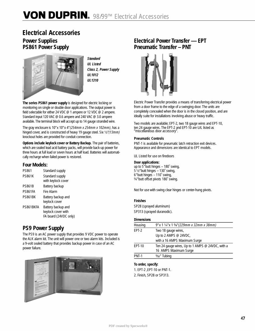
47474747
Power SuppliesPS861 Power Supply
StandardUL ListedClass 2, Power SupplyUL1012UL1310
The series PS861 power supply is designed for electric locking or monitoring on single or double door applications. The output power isfield selectable for either 24 VDC @ 1 ampere or 12 VDC @ 2 ampere.Standard input 120 VAC @ 0.6 ampere and 240 VAC @ 3.0 ampere available. The terminal block will accept up to 14 gauge stranded wire.
The gray enclosure is 10" x 10" x 4" (254mm x 254mm x 102mm), has ahinged cover, and is constructed of heavy 19 gauge steel. Six ¹�₂" (13mm)knockout holes are provided for conduit connection.
Options include keylock cover or Battery Backup. The pair of batteries,which are sealed lead acid battery packs, will provide back-up power forthree hours at full load or seven hours at half load. Batteries will automati-cally recharge when failed power is restored.
Four Models:PS861 Standard supplyPS861K Standard supply
with keylock coverPS861B Battery backupPS861FA Fire AlarmPS861BK Battery backup and
keylock coverPS861BKFA Battery backup and
keylock cover withFA board (24VDC only)
PS9 Power SupplyThe PS9 is an AC power supply that provides 9 VDC power to operatethe ALK alarm kit. The unit will power one or two alarm kits. Included isa 9-volt sealed battery that provides backup power in case of an ACpower failure.
Electrical Power Transfer –– EPTPneumatic Transfer – PNT
Electric Power Transfer provides a means of transferring electrical powerfrom a door frame to the edge of a swinging door. The units arecompletely concealed when the door is in the closed position, and areideally suite for installations involving abuse or heavy traffic.
Two models are available; EPT-2, two 18 gauge wires and EPT-10, ten 24 gauge wires. The EPT-2 and EPT-10 are U/L listed as“miscellaneous door accessory”.
Pneumatic ControlsPNT-1 is available for pneumatic latch retraction exit devices.Appearance and dimensions are identical to EPT models.
UL Listed for use on firedoors
Door applications:up to 5" butt hinges – 180 ̊swing, 5 ¹�₂" butt hinges – 130 ̊swing, 6" butt hinges – 110 ̊swing,³�₄" butt offset pivots 180˚ swing.
Not for use with swing clear hinges or center-hung pivots.
FinishesSP28 (sprayed aluminum) SP313 (sprayed duranodic).
DimensionsHousing 9" x 1 ¹�₄" x 1 ⁵�₈" (229mm x 32mm x 38mm)EPT-2 Two 18 gauge wires,
Up to 2 AMPS @ 24VDC, with a 16 AMPS Maximum Surge
EPT-10 Ten 24 gauge wires, Up to 1 AMPS @ 24VDC, with a16 AMPS Maximum Surge
PNT-1 ⁵�₃₂" Tubing
To order, specify:1. EPT-2 ,EPT-10 or PNT-1.2. Finish, SP28 or SP313.
98/99™ Electrical Accessories
Electrical Accessories
PDF created by Specworks®
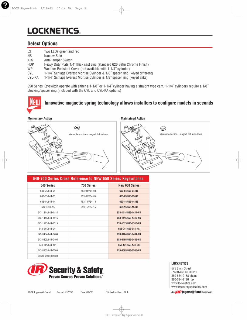
Maintained action - magnet dot side down,Momentary action - magnet dot side up.
Momentary Action Maintained Action
640-750 Series Cross Reference to NEW 650 Series Keyswitches
640 Series 750 Series New 650 Series
643-04/644-04 753-04/754-04 653-04/653-04-NS
643-05/644-05 753-05/754-05 653-05/653-05-NS
643-14/644-14 753-14/754-14 653-14/653-14-NS
643-15/64-15 753-15/754-15 653-15/653-15-NS
643-1414/644-1414 653-1414/653-1414-NS
643-1415/644-1415 653-1415/653-1415-NS
643-1515/644-1515 653-1515/653-1515-NS
643-041/644-041 653-041/653-041-NS
643-0404/644-0404 653-0404/653-0404-NS
643-0405/644-0405 653-0405/653-0405-NS
643-141/644-141 653-141/653-141-NS
643-0505/644-0505 653-0505/653-0505-NS
DA645 Discontinued
LOCKNETICS575 Birch StreetForestville, CT 06010860-584-9158 phone860-584-2136 faxwww.locknetics.comwww.irsecurityandsafety.com
2002 Ingersoll-Rand Form LK-2033 Rev. 09/02 Printed in the U.S.A.
Select OptionsL2 Two LEDs green and redNS Narrow StileATS Anti-Tamper SwitchHDP Heavy Duty Plate 1/4˝ thick cast zinc (standard 626 Satin Chrome Finish)WP Weather Resistant Cover (not available with 1-1/4˝ cylinder)CYL 1-1/4˝ Schlage Everest Mortise Cylinder & 1/8˝ spacer ring (keyed different)CYL-KA 1-1/4˝ Schlage Everest Mortise Cylinder & 1/8˝ spacer ring (keyed alike)
650 Series Keyswitch operate with either a 1-1/8˝ or 1-1/4˝ cylinder having a straight type cam. 1-1/4˝ cylinders require a 1/8˝blocking/spacer ring (included with the CYL and CYL-KA options)
Innovative magnetic spring technology allows installers to configure models in seconds
LOCK.Keyswitch 9/19/02 10:14 AM Page 2
PDF created by Specworks®
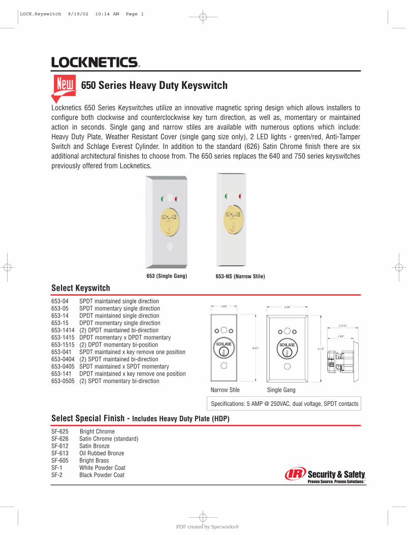
Locknetics 650 Series Keyswitches utilize an innovative magnetic spring design which allows installers to configure both clockwise and counterclockwise key turn direction, as well as, momentary or maintained action in seconds. Single gang and narrow stiles are available with numerous options which include: Heavy Duty Plate, Weather Resistant Cover (single gang size only), 2 LED lights - green/red, Anti-TamperSwitch and Schlage Everest Cylinder. In addition to the standard (626) Satin Chrome finish there are six additional architectural finishes to choose from. The 650 series replaces the 640 and 750 series keyswitchespreviously offered from Locknetics.
653 (Single Gang) 653-NS (Narrow Stile)
650 Series Heavy Duty Keyswitch
Select Keyswitch653-04 SPDT maintained single direction653-05 SPDT momentary single direction653-14 DPDT maintained single direction653-15 DPDT momentary single direction653-1414 (2) DPDT maintained bi-direction653-1415 DPDT momentary x DPDT momentary653-1515 (2) DPDT momentary bi-position653-041 SPDT maintained x key remove one position653-0404 (2) SPDT maintained bi-direction653-0405 SPDT maintained x SPDT momentary653-141 DPDT maintained x key remove one position653-0505 (2) SPDT momentary bi-direction
Select Special Finish - Includes Heavy Duty Plate (HDP)
SF-625 Bright ChromeSF-626 Satin Chrome (standard)SF-612 Satin BronzeSF-613 Oil Rubbed BronzeSF-605 Bright BrassSF-1 White Powder CoatSF-2 Black Powder Coat
Specifications: 5 AMP @ 250VAC, dual voltage, SPDT contacts
Narrow Stile Single Gang
LOCK.Keyswitch 9/19/02 10:14 AM Page 1
PDF created by Specworks®