catalog - rame valve
TRANSCRIPT

F - 1 7C A T A L O G
F o r g e d S t e e lVa l v e s
Vogt Valves Catalog and Application Manual VVENCT0000-06 08/17
2
Vogt Valves A History in the Making
In the late 1890s, Vogt pioneered the early development of ammonia absorption refrigeration systems that made artificial ice. This business, plus Vogt’s fledgling boiler business, created an internal need for quality valves that initiated Vogt’s early entry into the valve manufacturing business.The early reputation of Vogt’s quality valves and rapidly growing petroleum processing industry created an outside demand that would firmly establish Vogt in the mass production of high-quality forged steel valves.For more than 100 years, Vogt’s leadership has been evident in the production of forged steel gate, globe, angle and check valves in most popular materials, trims and bonnet configurations.Today, Vogt valves support a worldwide network of distributors with access to the world’s largest capability for manufacturing of forged steel valves.
3
Vogt Valves Catalog and Application Manual VVENCT0000-06 08/17
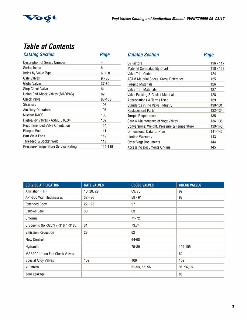
SERVICE APPLICATION GATE VALVES GLOBE VALVES CHECK VALVES
Alkylation (HF) 10, 28, 29 69, 70 92
API-600 Wall Thicknesses 32 - 36 58 - 61 98
Extended Body 22 - 25 57
Bellows Seal 30 63
Chlorine 71-72
Cryogenic (to -325°F) F316 / F316L 31 73,74
Emission Reduction 28 62
Flow Control 64-68
Hydraulic 75-80 104,105
MARPAC Union End Check Valves 82
Special Alloy Valves 109 109 109
Y-Pattern 51-53, 55, 56 95, 96, 97
Zero Leakage 85
Table of ContentsCatalog Section PageDescription of Series NumberSeries IndexIndex by Valve TypeGate ValvesGlobe Valves Stop Check ValveUnion End Check Valves (MARPAC)Check ValveStrainersAuxiliary OperatorsNuclear NACEHigh-alloy Valves - ASME B16.34Recommended Valve OrientationFlanged EndsButt Weld EndsThreaded & Socket WeldPressure-Temperature Service Rating
456, 7, 89 - 3637-80818283-105106107108109110111112113114-115
Catalog Section Page
Cv FactorsMaterial Compatability ChartValve Trim CodesASTM Material Specs. Cross ReferenceForging MaterialsValve Trim MaterialsValve Packing & Gasket MaterialsAbbreviations & Terms UsedStandards in the Valve IndustryReplacement PartsTorque RequirementsCare & Maintenance of Vogt ValvesConversions: Weight, Pressure & TemperatureDimensional Data for PipeLimited Warranty Other Vogt Documents Accessing Documents On-line
116 - 117118 - 123124 125126127128129130-131132-134135136-138139-140141-142143144145
Vogt Valves Catalog and Application Manual VVENCT0000-06 08/17
4
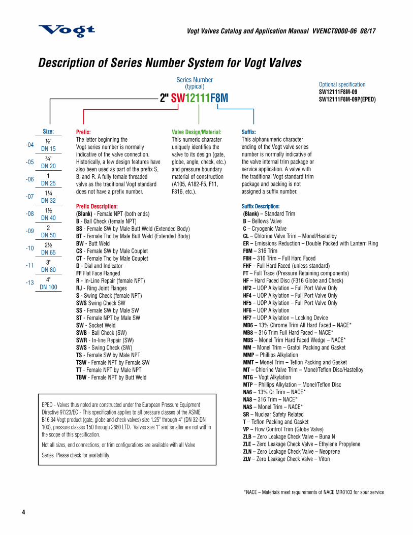
Description of Series Number System for Vogt Valves
EPED - Valves thus noted are constructed under the European Pressure Equipment Directive 97/23/EC - This specification applies to all pressure classes of the ASME B16.34 Vogt product (gate, globe and check valves) size 1.25" through 4" (DN 32-DN 100), pressure classes 150 through 2680 LTD. Valves size 1" and smaller are not within the scope of this specification.
Not all sizes, end connections, or trim configurations are available with all Valve
Series. Please check for availability.
Prefix:The letter beginning theVogt series number is normallyindicative of the valve connection.Historically, a few design features havealso been used as part of the prefix S,B, and R. A fully female threadedvalve as the traditional Vogt standarddoes not have a prefix number.
Prefix Description:(Blank) - Female NPT (both ends)B - Ball Check (female NPT)BS - Female SW by Male Butt Weld (Extended Body)BT - Female Thd by Male Butt Weld (Extended Body)BW - Butt WeldCS - Female SW by Male Couplet CT - Female Thd by Male CoupletD - Dial and IndicatorFF Flat Face Flanged R - In-Line Repair (female NPT)RJ - Ring Joint Flanges S - Swing Check (female NPT) SWS Swing Check SWSS - Female SW by Male SW ST - Female NPT by Male SW SW - Socket Weld SWB - Ball Check (SW) SWR - In-line Repair (SW) SWS - Swing Check (SW) TS - Female SW by Male NPT TSW - Female NPT by Female SW TT - Female NPT by Male NPTTBW - Female NPT by Butt Weld
Suffix:This alphanumeric characterending of the Vogt valve seriesnumber is normally indicative ofthe valve internal trim package orservice application. A valve withthe traditional Vogt standard trimpackage and packing is notassigned a suffix number.
Suffix Description:(Blank) – Standard TrimB – Bellows Valve C – Cryogenic Valve CL – Chlorine Valve Trim – Monel/Hastelloy ER – Emissions Reduction – Double Packed with Lantern Ring F8M – 316 TrimF8H – 316 Trim – Full Hard FacedFHF – Full Hard Faced (unless standard) FT – Full Trace (Pressure Retaining components)HF – Hard Faced Disc (F316 Globe and Check)HF2 – UOP Alkylation – Full Port Valve OnlyHF4 – UOP Alkylation – Full Port Valve OnlyHF5 – UOP Alkylation – Full Port Valve OnlyHF6 – UOP AlkylationHF7 – UOP Alkylation – Locking DeviceMB6 – 13% Chrome Trim All Hard Faced – NACE* MB8 – 316 Trim Full Hard Faced – NACE* MBS – Monel Trim Hard Faced Wedge – NACE*MM – Monel Trim – Grafoil Packing and Gasket MMP – Phillips Alkylation MMT – Monel Trim – Teflon Packing and Gasket MT – Chlorine Valve Trim – Monel/Teflon Disc/HastelloyMTG – Vogt Alkylation MTP – Phillips Alkylation – Monel/Teflon DiscNA6 – 13% Cr Trim – NACE*NA8 – 316 Trim – NACE*NAS – Monel Trim – NACE*SR – Nuclear Safety RelatedT – Teflon Packing and Gasket VP – Flow Control Trim (Globe Valve)ZLB – Zero Leakage Check Valve – Buna N ZLE – Zero Leakage Check Valve – Ethylene Propylene ZLN – Zero Leakage Check Valve – Neoprene ZLV – Zero Leakage Check Valve – Viton
2" SW12111F8M
Series Number(typical)
Valve Design/Material:This numeric characteruniquely identifies thevalve to its design (gate,globe, angle, check, etc.)and pressure boundarymaterial of construction(A105, A182-F5, F11,F316, etc.).
Size:½"
DN 15¾"
DN 201
DN 251¼
DN 321½
DN 402
DN 502½
DN 653"
DN 804"
DN 100
-04
-05
-06
-07
-08
-09
-10
-11
-13
Optional specificationSW12111F8M-09SW12111F8M-09P(EPED)
*NACE – Materials meet requirements of NACE MR0103 for sour service
5
Vogt Valves Catalog and Application Manual VVENCT0000-06 08/17
Suffix:This alphanumeric characterending of the Vogt valve seriesnumber is normally indicative ofthe valve internal trim package orservice application. A valve withthe traditional Vogt standard trimpackage and packing is notassigned a suffix number.
Suffix Description:(Blank) – Standard TrimB – Bellows Valve C – Cryogenic Valve CL – Chlorine Valve Trim – Monel/Hastelloy ER – Emissions Reduction – Double Packed with Lantern Ring F8M – 316 TrimF8H – 316 Trim – Full Hard FacedFHF – Full Hard Faced (unless standard) FT – Full Trace (Pressure Retaining components)HF – Hard Faced Disc (F316 Globe and Check)HF2 – UOP Alkylation – Full Port Valve OnlyHF4 – UOP Alkylation – Full Port Valve OnlyHF5 – UOP Alkylation – Full Port Valve OnlyHF6 – UOP AlkylationHF7 – UOP Alkylation – Locking DeviceMB6 – 13% Chrome Trim All Hard Faced – NACE* MB8 – 316 Trim Full Hard Faced – NACE* MBS – Monel Trim Hard Faced Wedge – NACE*MM – Monel Trim – Grafoil Packing and Gasket MMP – Phillips Alkylation MMT – Monel Trim – Teflon Packing and Gasket MT – Chlorine Valve Trim – Monel/Teflon Disc/HastelloyMTG – Vogt Alkylation MTP – Phillips Alkylation – Monel/Teflon DiscNA6 – 13% Cr Trim – NACE*NA8 – 316 Trim – NACE*NAS – Monel Trim – NACE*SR – Nuclear Safety RelatedT – Teflon Packing and Gasket VP – Flow Control Trim (Globe Valve)ZLB – Zero Leakage Check Valve – Buna N ZLE – Zero Leakage Check Valve – Ethylene Propylene ZLN – Zero Leakage Check Valve – Neoprene ZLV – Zero Leakage Check Valve – Viton
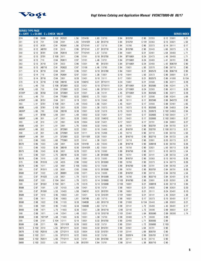
SERIES TYPE PAGEG = GATE L = GLOBE C = CHECK VALVE SERIES INDEX
S74 C 99 S698 C 102 R2522 L 56 12141B L 63 13710 C 84 B15761 C 90 32353 G 12 35801 G 21351 G 12 701 C 84 2591 L 55 12141ER L 62 B13710 C 84 S15761 C 101 32363 G 13 35821 L 50352 G 12 A701 C 91 R2591 L 56 CT12141 L 57 13718 C 84 15780 C 90 32373 G 14 36111 G 17353 G 12 AB701 C 91 2610 C 96 ST12141 L 57 B13718 C 84 B15780 C 90 32443 L 66 36373 L 15358 G 12 B701 C 84 R2610 C 97 TT12141 L 57 13750 C 84 15801 G 21 32461 L 64 36483 L 71361 G 13 S701 C 100 2611 C 96 12161 G 18 B13750 C 84 BT15801 G 24 32473 L 40 36493 L 71362 G 13 710 C 84 R2611 C 97 12181 L 46 13751 C 84 CT15801 G 24 32483 L 41 36701 C 90363 G 13 A710 C 91 2622 C 96 12301 48 B13751 C 84 ST15801 G 24 32493 L 42 B36701 C 90368 G 13 AB710 C 91 R2622 C 97 12188 L 46 13780 C 84 15821 L 50 32570 C 86 36710 C 90371 G 14 B710 C 84 2691 C 96 12321 G 10 B13780 C 84 15831 G 21 B32570 C 86 B36710 C 90372 G 14 718 C 84 R2691 G 97 12351 L 38 13921 G 10 15841 L 50 32573 C 86 36801 G 21373 G 14 B718 C 84 2801 G 20 12401 G 10 15111 G 17 15851 G 21 B32573 C 86 41000 G 134378 G 14 S718 C 100 2801B G 30 12401C G 31 BT15111 G 24 15861 G 21 32580 C 86 42211 G 28473 L 40 730 C 106 BT2801 G 22 12421 G 10 CT15111 G 24 BT15901 G 24 B32580 C 86 42241 L 70473B L 63 750 C 84 CT2801 G 22 12443 L 66 ST15111 G 24 CT15901 G 24 32583 C 86 43111 G 29473VP L 66 B750 C 84 ST2801 G 22 12501 L 38 15141 L 45 ST15901 G 24 B32583 C 86 43211 G 28478 L 40 751 C 84 TT2801 G 22 12501C L 73 15321 G 17 15921 G 17 32590 C 88 43241 L 69478VP L 66 B751 C 84 2811 G 19 12521 G 10 15343 L 68 16111 G 17 B32590 C 88 B43721 C 92483 L 41 S751 C 100 2821 L 49 12543 L 66 15351 L 45 16321 G 17 32593 C 88 52461 L 65483B L 63 S761 C 100 2831 G 20 12551 L 38 15373 G 15 16373 G 15 B32593 C 88 54853 C 94483VP L 66 780 C 84 2831B G 30 12601 G 32 15378 G 15 16378 G 15 S32673 C 102 54863 C 94488 L 41 B780 L 84 2841 L 49 12602 G 32 15401 G 17 16401 G 17 S32683 C 102 58431 L 77488VP L 66 801 L 47 2851 G 20 12603 G 32 15401C G 31 16421 G 17 S32693 C 102 59851 G 27493 L 42 810 L 51 2861 G 20 12604 G 32 15421 G 17 16521 G 17 32701 C 84 59951 G 27493B L 63 811 L 51 2891 L 76 12605 G 32 15443 L 68 16701 C 90 B32701 C 84 65703 G 21493VP L 66 822 L 51 BT2901 G 22 12921 G 10 15493 L 43 B16701 C 90 S32701 C 100 65713 G 21498 L 42 851 L 46 CT2901 G 22 13111 G 10 15498 L 43 16710 C 90 32710 C 84 65733 L 50498VP L 66 891 L 51 ST2901 G 22 13111ER G 28 15501 L 45 B16710 C 90 B32710 C 84 65723 L 50570 C 86 1003 L 60 TT2901 G 22 13141 L 38 15521 G 17 16718 C 90 32801 G 20 65773 G 21B570 C 86 1023 L 60 3801 G 20 13141B L 63 15543 L 68 B16718 C 90 32801B G 30 66703 G 26573 C 86 1033 G 36 3801B G 30 13141ER L 62 15551 L 45 16750 C 90 32821 L 50 66713 G 26B573 C 86 1043 G 36 3831 G 20 13321 G 10 15590 C 89 B16750 C 90 33111 G 10 66723 L 54578 C 86 1331 L 75 3831B G 30 13351 L 38 B15590 C 89 16751 C 90 33141 L 38 66733 L 54B578 C 86 1510 L 52 3991 L 80 13361 G 13 15593 C 89 B16751 C 90 33363 G 13 66743 G 26579 C 86 R1510 L 53 4835 C 98 13362 G 13 B15593 C 89 16760 C 90 33373 G 14 66773 G 26B579 C 86 1511 L 52 4881 C 105 13363 G 13 15598 C 89 B16760 C 90 33701 C 84 66783 L 54580 C 87 R1511 L 53 9091 C 93 13368 G 13 B15598 C 89 16761 C 90 B33701 C 84 66791 G 26B580 C 87 1522 L 52 B9091 C 93 13371 G 14 15599 C 89 B16761 C 90 33710 C 84 66793 L 54583 C 87 R1522 L 53 9821 L 79 13372 G 14 B15599 C 89 16780 C 90 B33710 C 84 82401 G 10B583 C 87 1551 C 104 9841 L 78 13373 G 14 S15693 C 103 B16780 C 90 33801 G 20 82501 L 38588 C 87 B1551 C 104 9871 L 78 13378 G 14 S15698 C 103 16801 G 21 33801B G 30 82718 C 84B588 C 87 1591 L 52 10103 L 59 13401 G 10 15701 C 90 16831 G 21 34835 C 98 82831 G 20589 C 87 R1591 L 53 10403 L 58 13401C G 31 B15701 C 90 16851 G 21 35111 G 24 83401 G 10B589 C 87 1610 C 95 10603 L 61 13421 G 10 S15701 C 101 16861 G 21 35141 L 45 83501 L 38590 C 88 1611 C 95 10683 L 61 13474B L 63 15710 C 90 16921 G 17 35373 G 15 85401 G 17B590 C 88 1622 C 95 11103 G 33 13483B L 63 B15710 C 90 21000 G 134 35443 L 68 85831 G 21
593 C 88 1691 C 95 11403 G 34 13493B L 63 15718 C 90 22141 L 72 35493 L 43 86401 G 17
B593 C 88 1871 L 75 11603 G 35 13501 L 38 B15718 C 90 22142 L 72 35590 C 89 86831 G 21598 C 88 1971 L 44 12041 L 48 13521 G 10 S15718 C 101 22461 L 64 B35590 C 89 88300 L 74B598 C 88 1971VP L 68 11683 G 35 13551 L 38 15750 C 90 22483 L 71 35593 C 89599 C 88 2191 C 104 12111 G 10 13601 G 32 B15750 C 90 22493 L 71 B35593 C 89B599 C 88 2271 106 12111ER G 28 13602 G 32 15751 C 90 22501 L 72 S35693 C 103S673 C 102 2510 L 55 BT12111 G 22 13603 G 32 B15751 C 90 22561 L 64 35701 C 90S678 C 102 R2510 L 56 CT12111 G 22 13604 G 32 S15751 C 101 23141 L 69 B35701 C 90S683 C 102 2511 L 55 ST12111 G 22 13605 G 32 15760 C 90 S32074 C 99 S35701 C 101S688 C 102 R2511 L 56 TT12111 G 22 13701 C 84 B15760 C 90 32111 G 10 35710 C 90S693 C 102 2522 L 55 12141 L 38 B13701 C 84 15761 C 90 32141 L 38 B35710 C 90
Vogt Valves Catalog and Application Manual VVENCT0000-06 08/17
6
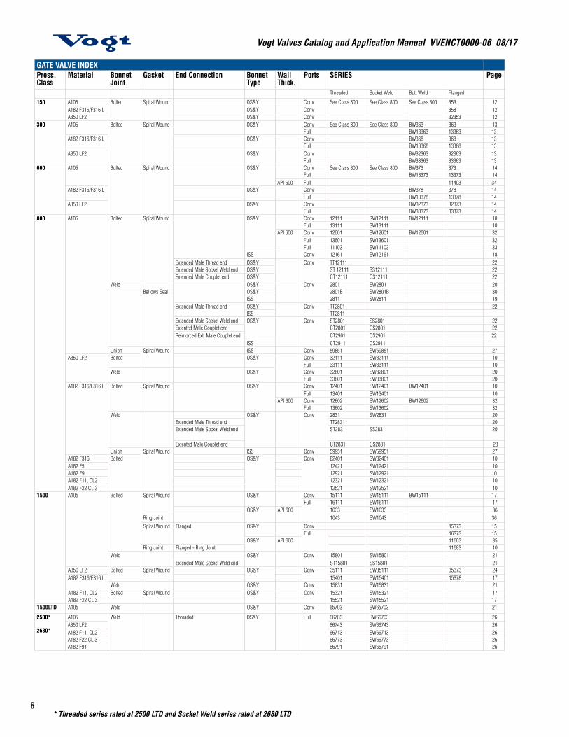
GATE VALVE INDEXPress. Class
Material Bonnet Joint
Gasket End Connection Bonnet Type
Wall Thick.
Ports SERIES Page
Threaded Socket Weld Butt Weld Flanged
150 A105 Bolted Spiral Wound OS&Y Conv See Class 800 See Class 800 See Class 300 353 12A182 F316/F316 L OS&Y Conv 358 12A350 LF2 OS&Y Conv 32353 12
300 A105 Bolted Spiral Wound OS&Y Conv See Class 800 See Class 800 BW363 363 13Full BW13363 13363 13
A182 F316/F316 L OS&Y Conv BW368 368 13Full BW13368 13368 13
A350 LF2 OS&Y Conv BW32363 32363 13Full BW33363 33363 13
600 A105 Bolted Spiral Wound OS&Y Conv See Class 800 See Class 800 BW373 373 14Full BW13373 13373 14
API 600 Full 11403 34A182 F316/F316 L OS&Y Conv BW378 378 14
Full BW13378 13378 14A350 LF2 OS&Y Conv BW32373 32373 14
Full BW33373 33373 14800 A105 Bolted Spiral Wound OS&Y Conv 12111 SW12111 BW12111 10
Full 13111 SW13111 10API 600 Conv 12601 SW12601 BW12601 32
Full 13601 SW13601 32Full 11103 SW11103 33
ISS Conv 12161 SW12161 18Extended Male Thread end OS&Y Conv TT12111 22Extended Male Socket Weld end OS&Y ST 12111 SS12111 22Extended Male Couplet end OS&Y CT12111 CS12111 22
Weld OS&Y Conv 2801 SW2801 20Bellows Seal OS&Y 2801B SW2801B 30
ISS 2811 SW2811 19Extended Male Thread end OS&Y Conv TT2801 22
ISS TT2811Extended Male Socket Weld end OS&Y Conv ST2801 SS2801 22Extented Male Couplet end CT2801 CS2801 22Reinforced Ext. Male Couplet end CT2901 CS2901 22
ISS CT2911 CS2911Union Spiral Wound ISS Conv 59851 SW59851 27
A350 LF2 Bolted OS&Y Conv 32111 SW32111 10Full 33111 SW33111 10
Weld OS&Y Conv 32801 SW32801 20Full 33801 SW33801 20
A182 F316/F316 L Bolted Spiral Wound OS&Y Conv 12401 SW12401 BW12401 10Full 13401 SW13401 10
API 600 Conv 12602 SW12602 BW12602 32Full 13602 SW13602 32
Weld OS&Y Conv 2831 SW2831 20Extended Male Thread end TT2831 20Extended Male Socket Weld end ST2831 SS2831 20
Extented Male Couplet end CT2831 CS2831 20Union Spiral Wound ISS Conv 59951 SW59951 27
A182 F316H Bolted OS&Y Conv 82401 SW82401 10A182 F5 12421 SW12421 10A182 F9 12921 SW12921 10A182 F11, CL2 12321 SW12321 10A182 F22 CL 3 12521 SW12521 10
1500 A105 Bolted Spiral Wound OS&Y Conv 15111 SW15111 BW15111 17Full 16111 SW16111 17
OS&Y API 600 1033 SW1033 36Ring Joint 1043 SW1043 36
Spiral Wound Flanged OS&Y Conv 15373 15Full 16373 15
OS&Y API 600 11603 35Ring Joint Flanged - Ring Joint 11683 10
Weld OS&Y Conv 15801 SW15801 21Extended Male Socket Weld end ST15801 SS15801 21
A350 LF2 Bolted Spiral Wound OS&Y Conv 35111 SW35111 35373 24A182 F316/F316 L 15401 SW15401 15378 17
Weld OS&Y Conv 15831 SW15831 21A182 F11, CL2 Bolted Spiral Wound OS&Y Conv 15321 SW15321 17A182 F22 CL 3 15521 SW15521 17
1500LTD A105 Weld OS&Y Conv 65703 SW65703 21
2500*
2680*
A105 Weld Threaded OS&Y Full 66703 SW66703 26A350 LF2 66743 SW66743 26A182 F11, CL2 66713 SW66713 26A182 F22 CL 3 66773 SW66773 26A182 F91 66791 SW66791 26
* Threaded series rated at 2500 LTD and Socket Weld series rated at 2680 LTD
7
Vogt Valves Catalog and Application Manual VVENCT0000-06 08/17
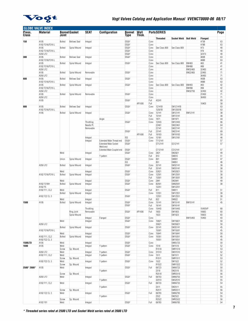
GLOBE VALVE INDEXPress. Class
Material Bonnet Joint
Gasket SEAT Configuration Bonnet Type
Wall Thick.
PortsSERIES Page
Threaded Socket Weld Butt Weld Flanged150 A105 Bolted Bellows Seal Integral OS&Y Conv 473B 63
A182 F316/F316 L OS&Y Conv 478B 63A105 Bolted Spiral Wound Integral OS&Y Conv See Class 800 See Class 800 473 40A182 F316/F316 L OS&Y Conv 478 40A350 LF2 OS&Y Conv 32473 40
300 A105 Bolted Bellows Seal Integral OS&Y Conv 483B 63A182 F316/F316 L Conv 488B 63A105 Bolted Spiral Wound Integral OS&Y Conv See Class 800 See Class 800 BW483 483 41A182 F316/F316 L Conv BW488 488 41A350 LF2 Conv BW32483 32483 41A105 Bolted Spiral Wound Removable OS&Y Conv BW22483 22483 71A350 LF2 Conv 36483 71
600 A105 Bolted Bellows Seal Integral OS&Y Conv 493B 63A182 F316/F316 L Conv 498B 63A105 Bolted Spiral Wound Integral OS&Y Conv See Class 800 See Class 800 BW493 493 42A182 F316/F316 L Conv BW498 498 42A350 LF2 Conv BW32793 32493 42A105 Bolted Spiral Wound Removable OS&Y Conv 22493 71A350 LF2 Conv 36493 71A105 OS&Y Full 43241 69
API 600 Full 10403 58800 A105 Bolted Bellows Seal Integral OS&Y Conv 12141B SW12141B 63
A182 F316/F316 L 12501B SW12501B 63A105 Bolted Spiral Wound Integral OS&Y Conv 12141 SW12141 BW12141 38
Full 13141 SW13141 38Angle Conv 1971 SW1971 44
Throttling OS&Y Conv 12443 SW12443 66Needle Pt. 22461 SW22461 64Removable 22141 SW22141 72
OS&Y Full 23141 SW23141 69API 600 Full 10103 SW10103 59
Integral ISS Conv 12181 SW12181 46Integral Extended Male Thread end OS&Y Conv TT12141 57
Extended Male Socket Weld end
OS&Y ST12141 SS12141 57
Extented Male Couplet end OS&Y CT12141 CS12141 57Weld Integral OS&Y Conv 2821 SW2821 49
Y pattern Full 810 SW810 51Union Spiral Wound Integral OS&Y Conv 801 SW801 47
ISS 851 SW851 46A350 LF2 Bolted Spiral Wound Integral OS&Y Conv 32141 SW32141 38
Full 33141 SW33141 38Weld Integral OS&Y Conv 32821 SW32821 50
A182 F316/F316 L Bolted Spiral Wound Integral OS&Y Conv 12501 SW12501 38Full 13501 SW13501 38
Weld Integral OS&Y Conv 2841 SW2841 49A182 F316H Bolted Spiral Wound Integral OS&Y Conv 82501 SW82501 38A182 F5 12251 SW12251A182 F11, CL2 Weld Integral OS&Y Full 811 SW811 51
Bolted Spiral Wound Integral Conv 12351 SW12351 38A182 F22 CL 3 OS&Y 12551 SW12551 38
Weld Integral Full 822 SW822 511500 A105 Bolted Spiral Wound Integral OS&Y
OS&YConv 15141 SW15141 BW15141 45Full 16141 SW16141
Throttling Conv 15443 SW15443 15493VP 68Ring Joint Removable OS&Y API 600 Full 1003 SW1003 10683 60Spiral Wound 1023 SW1023 10603 60
Integral Flanged OS&Y Conv BW15493 15493 43Weld Integral OS&Y Conv 15821 SW15821 50
A350 LF2 35821 SW35821 50Bolted Spiral Wound Integral OS&Y Conv 35141 SW35141 45
A182 F316/F316 L 15501 SW15501 45Weld Integral OS&Y Conv 15841 SW15841 50
A182 F11, CL2 Bolted Spiral Wound Integral OS&Y Conv 15351 SW15351 45A182 F22 CL 3 15551 SW15551 45
1500LTD A105 Weld Integral OS&Y Conv SW65723 501690 A105 Weld Integral Y pattern OS&Y Conv 1510 SW1510 52
Screw Sp. Wound R1510 SWR1510 53A350 LF2 Weld Integral Y pattern OS&Y Conv 31510 SW31510 52A182 F11, CL2 Weld Integral Y pattern OS&Y Conv 1511 SW1511 52
Screw Sp. Wound R1511 SWR1511 53A182 F22 CL 3 Weld Integral Y pattern OS&Y Conv 1522 SW1522 52
Screw Sp. Wound R1522 SWR1522 532500* 2680* A105 Weld Integral OS&Y Full 66723 SW66723 50
Y pattern 2510 SW2510 55Screw Sp. Wound R2510 SWR2510 56
A350 LF2 Weld Integral OS&Y Full 66753 SW66753 54Y pattern 32510 SW32510 55
A182 F11, CL2 Weld Integral OS&Y Full 66733 SW66733 54
Y pattern 2511 SW2511 55Screw Sp. Wound R2511 SWR2511 56
A182 F22 CL 3 Weld Integral OS&Y Full 66793 SW66793 54Y pattern 2522 SW2522 55
Screw Sp. Wound R2522 SWR2522 56A182 F91 Weld Integral OS&Y Full 66783 SW66783 54
* Threaded series rated at 2500 LTD and Socket Weld series rated at 2680 LTD
Vogt Valves Catalog and Application Manual VVENCT0000-06 08/17
8*Threaded series rated at 2500 LTD and Socket Weld series rated at 2680 LTD
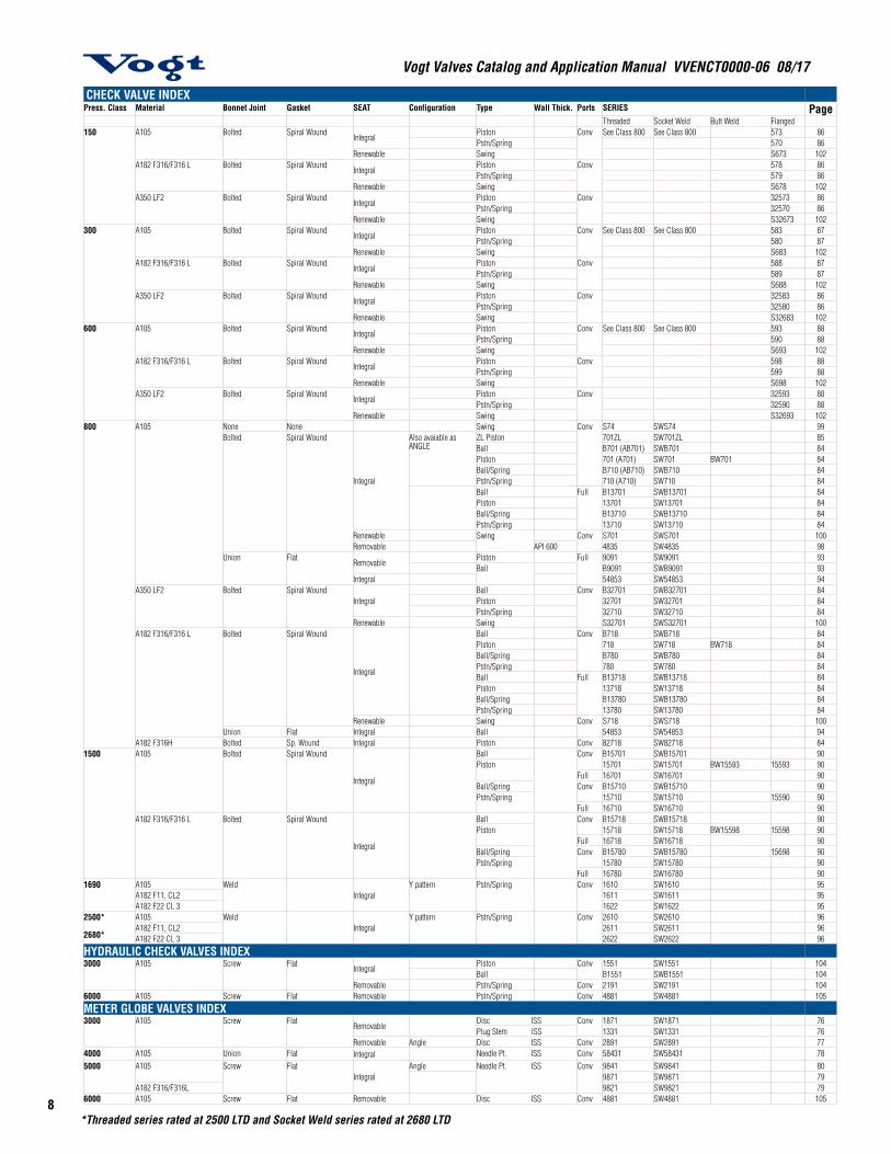
CHECK VALVE INDEXPress. Class Material Bonnet Joint Gasket SEAT Configuration Type Wall Thick. Ports SERIES Page
Threaded Socket Weld Butt Weld Flanged150 A105 Bolted Spiral Wound
IntegralPiston Conv See Class 800 See Class 800 573 86Pstn/Spring 570 86
Renewable Swing S673 102A182 F316/F316 L Bolted Spiral Wound
IntegralPiston Conv 578 86Pstn/Spring 579 86
Renewable Swing S678 102A350 LF2 Bolted Spiral Wound
IntegralPiston Conv 32573 86Pstn/Spring 32570 86
Renewable Swing S32673 102300 A105 Bolted Spiral Wound
IntegralPiston Conv See Class 800 See Class 800 583 87Pstn/Spring 580 87
Renewable Swing S683 102A182 F316/F316 L Bolted Spiral Wound
IntegralPiston Conv 588 87Pstn/Spring 589 87
Renewable Swing S688 102A350 LF2 Bolted Spiral Wound
IntegralPiston Conv 32583 86Pstn/Spring 32580 86
Renewable Swing S32683 102600 A105 Bolted Spiral Wound
IntegralPiston Conv See Class 800 See Class 800 593 88Pstn/Spring 590 88
Renewable Swing S693 102A182 F316/F316 L Bolted Spiral Wound
IntegralPiston Conv 598 88Pstn/Spring 599 88
Renewable Swing S698 102A350 LF2 Bolted Spiral Wound
IntegralPiston Conv 32593 88Pstn/Spring 32590 88
Renewable Swing S32693 102800 A105 None None Swing Conv S74 SWS74 99
Bolted Spiral Wound
Integral
Also avaiable as ANGLE
ZL Piston 701ZL SW701ZL 85Ball B701 (AB701) SWB701 84Piston 701 (A701) SW701 BW701 84Ball/Spring B710 (AB710) SWB710 84Pstn/Spring 710 (A710) SW710 84Ball Full B13701 SWB13701 84Piston 13701 SW13701 84Ball/Spring B13710 SWB13710 84Pstn/Spring 13710 SW13710 84
Renewable Swing Conv S701 SWS701 100Removable API 600 4835 SW4835 98
Union FlatRemovable
Piston Full 9091 SW9091 93Ball B9091 SWB9091 93
Integral 54853 SW54853 94A350 LF2 Bolted Spiral Wound
IntegralBall Conv B32701 SWB32701 84Piston 32701 SW32701 84Pstn/Spring 32710 SW32710 84
Renewable Swing S32701 SWS32701 100A182 F316/F316 L Bolted Spiral Wound
Integral
Ball Conv B718 SWB718 84Piston 718 SW718 BW718 84Ball/Spring B780 SWB780 84Pstn/Spring 780 SW780 84Ball Full B13718 SWB13718 84Piston 13718 SW13718 84Ball/Spring B13780 SWB13780 84Pstn/Spring 13780 SW13780 84
Renewable Swing Conv S718 SWS718 100Union Flat Integral Ball 54853 SW54853 94
A182 F316H Bolted Sp. Wound Integral Piston Conv 82718 SW82718 841500 A105 Bolted Spiral Wound
Integral
Ball Conv B15701 SWB15701 90Piston 15701 SW15701 BW15593 15593 90
Full 16701 SW16701 90Ball/Spring Conv B15710 SWB15710 90Pstn/Spring 15710 SW15710 15590 90
Full 16710 SW16710 90A182 F316/F316 L Bolted Spiral Wound
Integral
Ball Conv B15718 SWB15718 90Piston 15718 SW15718 BW15598 15598 90
Full 16718 SW16718 90Ball/Spring Conv B15780 SWB15780 15698 90Pstn/Spring 15780 SW15780 90
Full 16780 SW16780 901690 A105 Weld
IntegralY pattern Pstn/Spring Conv 1610 SW1610 95
A182 F11, CL2 1611 SW1611 95A182 F22 CL 3 1622 SW1622 95
2500*
2680*
A105 WeldIntegral
Y pattern Pstn/Spring Conv 2610 SW2610 96A182 F11, CL2 2611 SW2611 96A182 F22 CL 3 2622 SW2622 96
HYDRAULIC CHECK VALVES INDEX3000 A105 Screw Flat
IntegralPiston Conv 1551 SW1551 104Ball B1551 SWB1551 104
Removable Pstn/Spring Conv 2191 SW2191 1046000 A105 Screw Flat Removable Pstn/Spring Conv 4881 SW4881 105
METER GLOBE VALVES INDEX3000 A105 Screw Flat
RemovableDisc ISS Conv 1871 SW1871 76Plug Stem ISS 1331 SW1331 76
Removable Angle Disc ISS Conv 2891 SW2891 774000 A105 Union Flat Integral Needle Pt. ISS Conv 58431 SW58431 785000 A105 Screw Flat
IntegralAngle Needle Pt. ISS Conv 9841 SW9841 80
9871 SW9871 79A182 F316/F316L 9821 SW9821 79
6000 A105 Screw Flat Removable Disc ISS Conv 4881 SW4881 105
9
Vogt Valves Catalog and Application Manual VVENCT0000-06 08/17
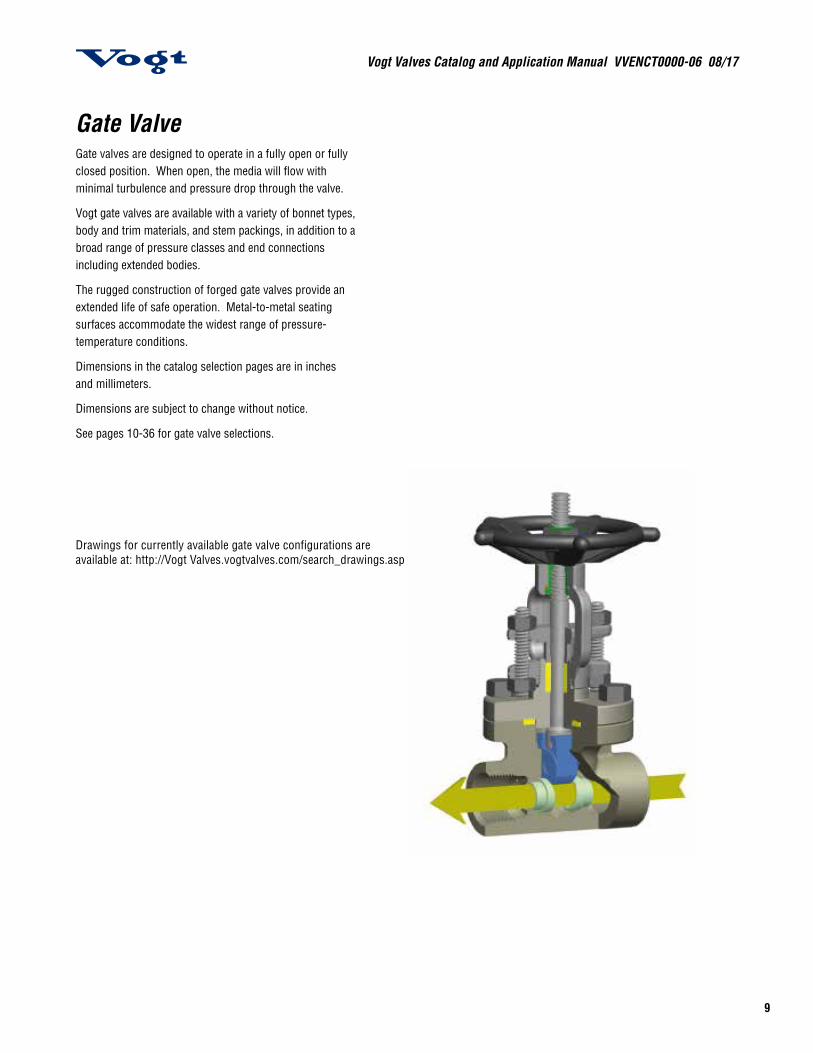
Gate ValveGate valves are designed to operate in a fully open or fully closed position. When open, the media will flow with minimal turbulence and pressure drop through the valve.
Vogt gate valves are available with a variety of bonnet types, body and trim materials, and stem packings, in addition to a broad range of pressure classes and end connections including extended bodies.
The rugged construction of forged gate valves provide an extended life of safe operation. Metal-to-metal seating surfaces accommodate the widest range of pressure-temperature conditions.
Dimensions in the catalog selection pages are in inches and millimeters.
Dimensions are subject to change without notice.
See pages 10-36 for gate valve selections.
Drawings for currently available gate valve configurations are available at: http://Vogt Valves.vogtvalves.com/search_drawings.asp

Vogt Valves Catalog and Application Manual VVENCT0000-06 08/17
10
12111 Gate Valve Class 800 Gate Valve Conventional Port Full Port
The Core of the Pressure Class 150, 300, 600 & 800 Gate Valve
CONNECTION CONV PORT FULL PORT BODY/BONNET TRIM RATING
Threaded Socket Weld (SW)Threaded/Socket Weld (TSW)Butt Weld (BW)*
12111 13111 A105 13 Cr 1975 PSI @ 100 F 136.2 BAR @ 38 C
32111 33111 A350 LF2 13 Cr 1975 PSI @ -50 F 136.2 BAR @ -46 C
12401 13401 F316/F316L 3161920 PSI @ 100 F 132.4 BAR @ 38 C
82401 83401 F316H 316H
12321 13321 F11,Cl.2(1-1/4 Cr.)
13 Cr 2000 PSI @ 100 F 137.9 BAR @ 38 C12521 13521 F22,Cl.3(2-1/4 Cr.)
12421 13421 F5(5 Cr.)
12921 13921 F9(9 Cr.)
(UOP) Universal Oil Products Approved - For HF Alkylation Service
CONNECTION CONV PORT FULL PORT BODY/BONNET TRIM RATING
ThreadedSocket Weld (SW)
12111HF6 A105 13 Cr 1975 PSI @ 100 F 136.2 BAR @ 38 C
13111HF4 A105 Monel 1975 PSI @ 100 F 136.2 BAR @ 38 C
12111HF7 A105 13 Cr 1975 PSI @ 100 F 136.2 BAR @ 38 C
13111HF5 A105 Monel 1975 PSI @ 100 F 136.2 BAR @ 38 C
*See page 16 for Butt Weld Series Gate Valves
See pages 12 - 14
11
Vogt Valves Catalog and Application Manual VVENCT0000-06 08/17
11
Vogt Valves Catalog and Application Manual VVENCT0000-06 08/17
Refer to page 4 for optional trim and service configurations.Refer to pages 126 & 127 for full materials description.
Refer to page 111-113 for end connections.Refer to pages 114-115 for other ratings
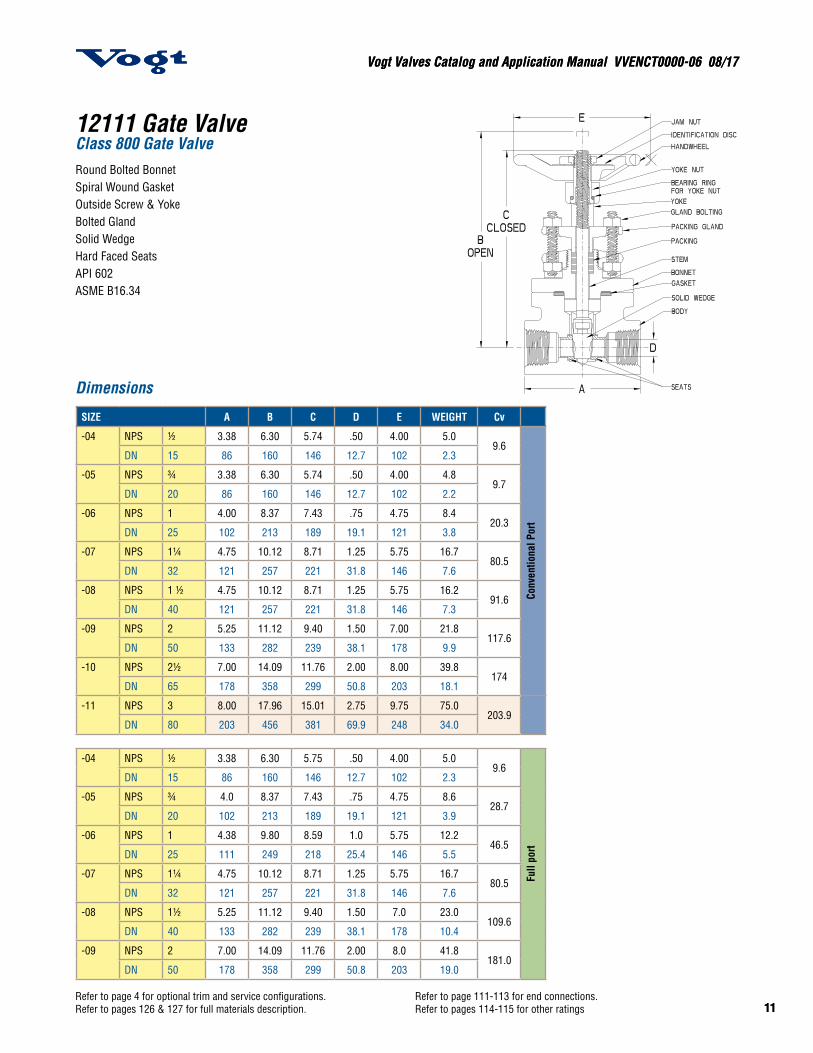
12111 Gate Valve Class 800 Gate ValveRound Bolted BonnetSpiral Wound GasketOutside Screw & YokeBolted GlandSolid WedgeHard Faced SeatsAPI 602ASME B16.34
A105
and
LF
2 ON
LY
Dimensions
SIZE A B C D E WEIGHT Cv
-04 NPS ½ 3.38 6.30 5.74 .50 4.00 5.09.6
Conv
entio
nal P
ort
DN 15 86 160 146 12.7 102 2.3
-05 NPS ¾ 3.38 6.30 5.74 .50 4.00 4.89.7
DN 20 86 160 146 12.7 102 2.2
-06 NPS 1 4.00 8.37 7.43 .75 4.75 8.420.3
DN 25 102 213 189 19.1 121 3.8
-07 NPS 1¼ 4.75 10.12 8.71 1.25 5.75 16.780.5
DN 32 121 257 221 31.8 146 7.6
-08 NPS 1 ½ 4.75 10.12 8.71 1.25 5.75 16.291.6
DN 40 121 257 221 31.8 146 7.3
-09 NPS 2 5.25 11.12 9.40 1.50 7.00 21.8117.6
DN 50 133 282 239 38.1 178 9.9
-10 NPS 2½ 7.00 14.09 11.76 2.00 8.00 39.8174
DN 65 178 358 299 50.8 203 18.1
-11 NPS 3 8.00 17.96 15.01 2.75 9.75 75.0203.9
DN 80 203 456 381 69.9 248 34.0
-04 NPS ½ 3.38 6.30 5.75 .50 4.00 5.09.6
Full
port
DN 15 86 160 146 12.7 102 2.3
-05 NPS ¾ 4.0 8.37 7.43 .75 4.75 8.628.7
DN 20 102 213 189 19.1 121 3.9
-06 NPS 1 4.38 9.80 8.59 1.0 5.75 12.246.5
DN 25 111 249 218 25.4 146 5.5
-07 NPS 1¼ 4.75 10.12 8.71 1.25 5.75 16.780.5
DN 32 121 257 221 31.8 146 7.6
-08 NPS 1½ 5.25 11.12 9.40 1.50 7.0 23.0109.6
DN 40 133 282 239 38.1 178 10.4
-09 NPS 2 7.00 14.09 11.76 2.00 8.0 41.8181.0
DN 50 178 358 299 50.8 203 19.0
Vogt Valves Catalog and Application Manual VVENCT0000-06 08/17
12
Vogt Valves Catalog and Application Manual VVENCT0000-06 08/17
12Refer to page 4 for optional trim and service configurations.Refer to pages 126 & 127 for full materials description.
Refer to page 111-113 for end connections.Refer to pages 114-115 for other ratings
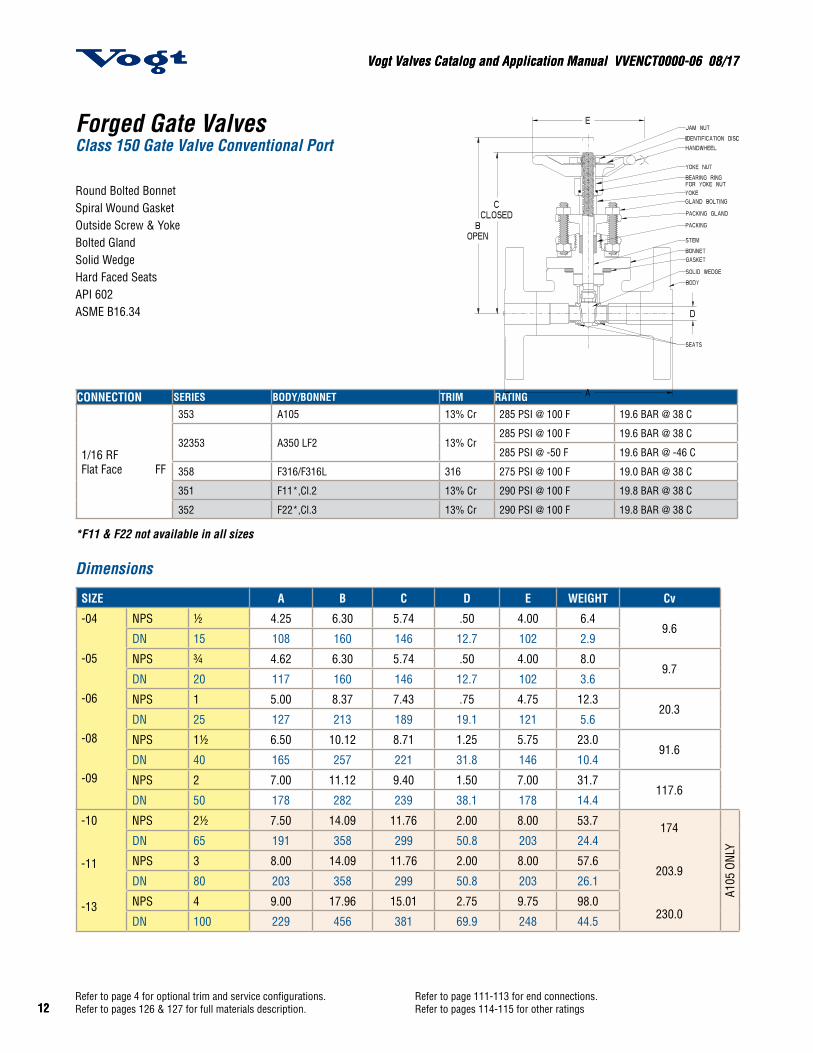
Forged Gate ValvesClass 150 Gate Valve Conventional Port
Round Bolted BonnetSpiral Wound GasketOutside Screw & YokeBolted GlandSolid WedgeHard Faced SeatsAPI 602ASME B16.34
CONNECTION SERIES BODY/BONNET TRIM RATING
1/16 RFFlat Face FF
353 A105 13% Cr 285 PSI @ 100 F 19.6 BAR @ 38 C
32353 A350 LF2 13% Cr285 PSI @ 100 F 19.6 BAR @ 38 C
285 PSI @ -50 F 19.6 BAR @ -46 C
358 F316/F316L 316 275 PSI @ 100 F 19.0 BAR @ 38 C
351 F11*,Cl.2 13% Cr 290 PSI @ 100 F 19.8 BAR @ 38 C
352 F22*,Cl.3 13% Cr 290 PSI @ 100 F 19.8 BAR @ 38 C
*F11 & F22 not available in all sizes
Dimensions
SIZE A B C D E WEIGHT Cv
-04
-05
-06
-08
-09
NPS ½ 4.25 6.30 5.74 .50 4.00 6.49.6
DN 15 108 160 146 12.7 102 2.9
NPS ¾ 4.62 6.30 5.74 .50 4.00 8.09.7
DN 20 117 160 146 12.7 102 3.6
NPS 1 5.00 8.37 7.43 .75 4.75 12.320.3
DN 25 127 213 189 19.1 121 5.6
NPS 1½ 6.50 10.12 8.71 1.25 5.75 23.091.6
DN 40 165 257 221 31.8 146 10.4
NPS 2 7.00 11.12 9.40 1.50 7.00 31.7117.6
DN 50 178 282 239 38.1 178 14.4
-10
-11
-13
NPS 2½ 7.50 14.09 11.76 2.00 8.00 53.7 174
203.9
230.0
A105
ONL
YDN 65 191 358 299 50.8 203 24.4
NPS 3 8.00 14.09 11.76 2.00 8.00 57.6
DN 80 203 358 299 50.8 203 26.1
NPS 4 9.00 17.96 15.01 2.75 9.75 98.0
DN 100 229 456 381 69.9 248 44.5

13
Vogt Valves Catalog and Application Manual VVENCT0000-06 08/17
13
Vogt Valves Catalog and Application Manual VVENCT0000-06 08/17
Refer to page 4 for optional trim and service configurations.Refer to pages 126 & 127 for full materials description.
Refer to page 111-113 for end connections.Refer to pages 114-115 for other ratings
CONVENTIONAL PORT
SIZE A B C D E WEIGHT Cv
-04 NPS ½ 5.5 6.30 5.74 .50 4.00 8.09.6
DN 15 140 160 146 12.7 102 3.6
-05 NPS ¾ 6.00 6.30 5.74 .50 4.00 10.89.7
DN 20 152 160 146 12.7 102 4.9
-06 NPS 1 6.50 8.37 7.43 .75 4.75 15.520.3
DN 25 165 213 189 19.1 121 7.0
-08 NPS 1½ 7.50 10.12 8.71 1.25 5.75 29.291.6
DN 40 191 257 221 31.8 146 13.2
-09 NPS 2 8.50 11.12 9.40 1.50 7.00 37.6117.6
DN 50 216 282 239 38.1 178 17.1
-10 NPS 2½ 9.50 14.09 11.76 2.00 8.00 61.6174
DN 65 241 358 299 50.8 203 27.9
-11 NPS 3 11.12 14.09 11.76 2.00 8.00 71.6203.9
DN 80 282 358 299 50.8 203 32.5
-13 NPS 4 12.00 17.96 15.01 2.75 9.75 121.9230.0
DN 100 305 456 381 69.9 248 55.3
A105
ONL
Y
FULL PORT
SIZE A B C D E WEIGHT Cv
-04 NPS ½ 5.50 6.30 5.74 .50 4.00 8.69.6
DN 15 140 160 146 12.7 102 3.9
-05 NPS ¾ 6.00 8.37 7.44 .75 4.75 13.928.7
DN 20 152 213 189 19.1 121 6.3
-06 NPS 1 6.50 9.80 8.59 1.00 5.75 18.546.5
DN 25 165 249 218 25.4 146 8.4
-08 NPS 1½ 7.50 11.12 9.40 1.50 7.00 33.2109.6
DN 40 191 282 239 38.1 178 15.1
-09 NPS 2 8.50 14.09 11.76 2.00 8.00 53.1181.0
DN 50 216 358 299 50.8 203 24.1
CONNECTION CONV PORT FULL PORT BODY/BONNET TRIM RATING
1/16 RFFlat Face FF
363 13363 A105 13% Cr 740 PSI @ 100 F 51.1 BAR @ 38 C
32363 33363 A350 LF2 13% Cr740 PSI @ 100 F 51.1 BAR @ 38 C
740 PSI @ -50 F 51.1 BAR @ -46 C
368 13368 F316/F316L 316 720 PSI @ 100 F 49.6 BAR @ 38 C
361 13361 F11*,Cl.2 13% Cr 750 PSI @ 100 F 51.7 BAR @ 38 C
362 13362 F22*,Cl.3 13% Cr 750 PSI @ 100 F 51.7 BAR @ 38 C
Forged Gate ValvesClass 300 Gate Valve
Conventional PortFull Port
Round Bolted BonnetSpiral Wound GasketOutside Screw & YokeBolted GlandSolid WedgeHard Faced SeatsAPI 602ASME B16.34
*F11 & F22 not available in all sizes
SEE PAGE 112 FOR BUTT WELD ENDS
Dimensions
Vogt Valves Catalog and Application Manual VVENCT0000-06 08/17
14
Vogt Valves Catalog and Application Manual VVENCT0000-06 08/17
14Refer to page 4 for optional trim and service configurations.Refer to pages 126 & 127 for full materials description.
Refer to page 111-113 for end connections.Refer to pages 114-115 for other ratings
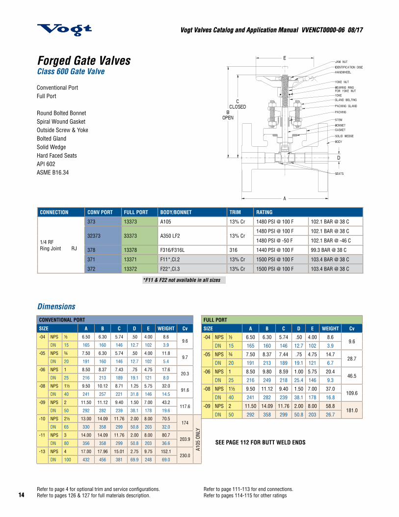
CONNECTION CONV PORT FULL PORT BODY/BONNET TRIM RATING
1/4 RFRing Joint RJ
373 13373 A105 13% Cr 1480 PSI @ 100 F 102.1 BAR @ 38 C
32373 33373 A350 LF2 13% Cr1480 PSI @ 100 F 102.1 BAR @ 38 C
1480 PSI @ -50 F 102.1 BAR @ -46 C
378 13378 F316/F316L 316 1440 PSI @ 100 F 99.3 BAR @ 38 C
371 13371 F11*,Cl.2 13% Cr 1500 PSI @ 100 F 103.4 BAR @ 38 C
372 13372 F22*,Cl.3 13% Cr 1500 PSI @ 100 F 103.4 BAR @ 38 C
Forged Gate Valves Class 600 Gate Valve
Conventional Port Full Port
Round Bolted BonnetSpiral Wound GasketOutside Screw & YokeBolted GlandSolid WedgeHard Faced SeatsAPI 602ASME B16.34
*F11 & F22 not available in all sizes
CONVENTIONAL PORT
SIZE A B C D E WEIGHT Cv-04 NPS ½ 6.50 6.30 5.74 .50 4.00 8.6
9.6DN 15 165 160 146 12.7 102 3.9
-05 NPS ¾ 7.50 6.30 5.74 .50 4.00 11.89.7
DN 20 191 160 146 12.7 102 5.4
-06 NPS 1 8.50 8.37 7.43 .75 4.75 17.620.3
DN 25 216 213 189 19.1 121 8.0
-08 NPS 1½ 9.50 10.12 8.71 1.25 5.75 32.091.6
DN 40 241 257 221 31.8 146 14.5
-09 NPS 2 11.50 11.12 9.40 1.50 7.00 43.2117.6
DN 50 292 282 239 38.1 178 19.6
-10 NPS 2½ 13.00 14.09 11.76 2.00 8.00 70.5174
DN 65 330 358 299 50.8 203 32.0
-11 NPS 3 14.00 14.09 11.76 2.00 8.00 80.7203.9
DN 80 356 358 299 50.8 203 36.6
-13 NPS 4 17.00 17.96 15.01 2.75 9.75 152.1230.0
DN 100 432 456 381 69.9 248 69.0
A105
ONL
Y
FULL PORT
SIZE A B C D E WEIGHT Cv
-04 NPS ½ 6.50 6.30 5.74 .50 4.00 8.69.6
DN 15 165 160 146 12.7 102 3.9
-05 NPS ¾ 7.50 8.37 7.44 .75 4.75 14.728.7
DN 20 191 213 189 19.1 121 6.7
-06 NPS 1 8.50 9.80 8.59 1.00 5.75 20.446.5
DN 25 216 249 218 25.4 146 9.3
-08 NPS 1½ 9.50 11.12 9.40 1.50 7.00 37.0109.6
DN 40 241 282 239 38.1 178 16.8
-09 NPS 2 11.50 14.09 11.76 2.00 8.00 58.8181.0
DN 50 292 358 299 50.8 203 26.7
SEE PAGE 112 FOR BUTT WELD ENDS
Dimensions
Vogt Valves Catalog and Application Manual VVENCT0000-06 08/17
110
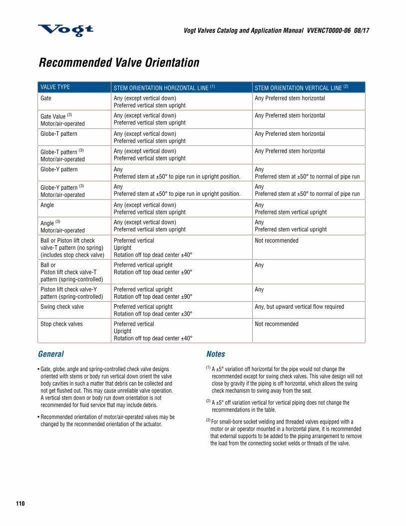
General • Gate, globe, angle and spring-controlled check valve designs
oriented with stems or body run vertical down orient the valve body cavities in such a matter that debris can be collected and not get flushed out. This may cause unreliable valve operation. A vertical stem down or body run down orientation is not recommended for fluid service that may include debris.
• Recommended orientation of motor/air-operated valves may be changed by the recommended orientation of the actuator.
Notes (1) A ±5° variation off horizontal for the pipe would not change the
recommended except for swing check valves. This valve design will not close by gravity if the piping is off horizontal, which allows the swing check mechanism to swing away from the seat.
(2) A ±5° off variation vertical for vertical piping does not change the recommendations in the table.
(3) For small-bore socket welding and threaded valves equipped with a motor or air operator mounted in a horizontal plane, it is recommended that external supports to be added to the piping arrangement to remove the load from the connecting socket welds or threads of the valve.
Recommended Valve Orientation
VALVE TYPE STEM ORIENTATION HORIZONTAL LINE (1) STEM ORIENTATION VERTICAL LINE (2)
Gate Any (except vertical down)Preferred vertical stem upright
Any Preferred stem horizontal
Gate Value (3)
Motor/air-operatedAny (except vertical down)Preferred vertical stem upright
Any Preferred stem horizontal
Globe-T pattern Any (except vertical down)Preferred vertical stem upright
Any Preferred stem horizontal
Globe-T pattern (3)
Motor/air-operatedAny (except vertical down)Preferred vertical stem upright
Any Preferred stem horizontal
Globe-Y pattern AnyPreferred stem at ±50° to pipe run in upright position.
AnyPreferred stem at ±50° to normal of pipe run
Globe-Y pattern (3)
Motor/air-operatedAnyPreferred stem at ±50° to pipe run in upright position.
AnyPreferred stem at ±50° to normal of pipe run
Angle Any (except vertical down)Preferred vertical stem upright
AnyPreferred stem vertical upright
Angle (3)
Motor/air-operatedAny (except vertical down)Preferred vertical stem upright
AnyPreferred stem vertical upright
Ball or Piston lift check valve-T pattern (no spring) (includes stop check valve)
Preferred verticalUprightRotation off top dead center ±40°
Not recommended
Ball orPiston lift check valve-T pattern (spring-controlled)
Preferred vertical uprightRotation off top dead center ±90°
Any
Piston lift check valve-Y pattern (spring-controlled)
Preferred vertical uprightRotation off top dead center ±90°
Any
Swing check valve Preferred vertical uprightRotation off top dead center ±30°
Any, but upward vertical flow required
Stop check valves Preferred verticalUprightRotation off top dead center ±40°
Not recommended
111
Vogt Valves Catalog and Application Manual VVENCT0000-06 08/17
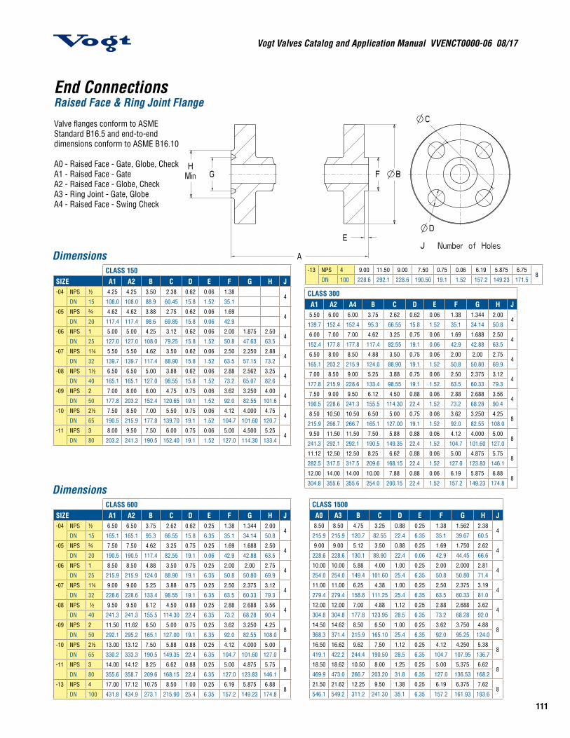
End ConnectionsRaised Face & Ring Joint Flange
Valve flanges conform to ASMEStandard B16.5 and end-to-enddimensions conform to ASME B16.10
A0 - Raised Face - Gate, Globe, CheckA1 - Raised Face - GateA2 - Raised Face - Globe, CheckA3 - Ring Joint - Gate, GlobeA4 - Raised Face - Swing Check
CLASS 150SIZE A1 A2 B C D E F G H J-04 NPS ½ 4.25 4.25 3.50 2.38 0.62 0.06 1.38
4DN 15 108.0 108.0 88.9 60.45 15.8 1.52 35.1
-05 NPS ¾ 4.62 4.62 3.88 2.75 0.62 0.06 1.694
DN 20 117.4 117.4 98.6 69.85 15.8 0.06 42.9
-06 NPS 1 5.00 5.00 4.25 3.12 0.62 0.06 2.00 1.875 2.504
DN 25 127.0 127.0 108.0 79.25 15.8 1.52 50.8 47.63 63.5
-07 NPS 1¼ 5.50 5.50 4.62 3.50 0.62 0.06 2.50 2.250 2.884
DN 32 139.7 139.7 117.4 88.90 15.8 1.52 63.5 57.15 73.2
-08 NPS 1½ 6.50 6.50 5.00 3.88 0.62 0.06 2.88 2.562 3.254
DN 40 165.1 165.1 127.0 98.55 15.8 1.52 73.2 65.07 82.6
-09 NPS 2 7.00 8.00 6.00 4.75 0.75 0.06 3.62 3.250 4.004
DN 50 177.8 203.2 152.4 120.65 19.1 1.52 92.0 82.55 101.6
-10 NPS 2½ 7.50 8.50 7.00 5.50 0.75 0.06 4.12 4.000 4.754
DN 65 190.5 215.9 177.8 139.70 19.1 1.52 104.7 101.60 120.7
-11 NPS 3 8.00 9.50 7.50 6.00 0.75 0.06 5.00 4.500 5.254
DN 80 203.2 241.3 190.5 152.40 19.1 1.52 127.0 114.30 133.4
CLASS 600SIZE A1 A2 B C D E F G H J-04 NPS ½ 6.50 6.50 3.75 2.62 0.62 0.25 1.38 1.344 2.00
4DN 15 165.1 165.1 95.3 66.55 15.8 6.35 35.1 34.14 50.8
-05 NPS ¾ 7.50 7.50 4.62 3.25 0.75 0.25 1.69 1.688 2.504
DN 20 190.5 190.5 117.4 82.55 19.1 0.06 42.9 42.88 63.5
-06 NPS 1 8.50 8.50 4.88 3.50 0.75 0.25 2.00 2.00 2.754
DN 25 215.9 215.9 124.0 88.90 19.1 6.35 50.8 50.80 69.9
-07 NPS 1¼ 9.00 9.00 5.25 3.88 0.75 0.25 2.50 2.375 3.124
DN 32 228.6 228.6 133.4 98.55 19.1 6.35 63.5 60.33 79.3
-08 NPS ½ 9.50 9.50 6.12 4.50 0.88 0.25 2.88 2.688 3.564
DN 40 241.3 241.3 155.5 114.30 22.4 6.35 73.2 68.28 90.4
-09 NPS 2 11.50 11.62 6.50 5.00 0.75 0.25 3.62 3.250 4.258
DN 50 292.1 295.2 165.1 127.00 19.1 6.35 92.0 82.55 108.0
-10 NPS 2½ 13.00 13.12 7.50 5.88 0.88 0.25 4.12 4.000 5.008
DN 65 330.2 333.3 190.5 149.35 22.4 6.35 104.7 101.60 127.0
-11 NPS 3 14.00 14.12 8.25 6.62 0.88 0.25 5.00 4.875 5.758
DN 80 355.6 358.7 209.6 168.15 22.4 6.35 127.0 123.83 146.1
-13 NPS 4 17.00 17.12 10.75 8.50 1.00 0.25 6.19 5.875 6.888
DN 100 431.8 434.9 273.1 215.90 25.4 6.35 157.2 149.23 174.8
-13 NPS 4 9.00 11.50 9.00 7.50 0.75 0.06 6.19 5.875 6.758
DN 100 228.6 292.1 228.6 190.50 19.1 1.52 157.2 149.23 171.5
CLASS 300A1 A2 A4 B C D E F G H J5.50 6.00 6.00 3.75 2.62 0.62 0.06 1.38 1.344 2.00
4139.7 152.4 152.4 95.3 66.55 15.8 1.52 35.1 34.14 50.8
6.00 7.00 7.00 4.62 3.25 0.75 0.06 1.69 1.688 2.504
152.4 177.8 177.8 117.4 82.55 19.1 0.06 42.9 42.88 63.5
6.50 8.00 8.50 4.88 3.50 0.75 0.06 2.00 2.00 2.754
165.1 203.2 215.9 124.0 88.90 19.1 1.52 50.8 50.80 69.9
7.00 8.50 9.00 5.25 3.88 0.75 0.06 2.50 2.375 3.124
177.8 215.9 228.6 133.4 98.55 19.1 1.52 63.5 60.33 79.3
7.50 9.00 9.50 6.12 4.50 0.88 0.06 2.88 2.688 3.564
190.5 228.6 241.3 155.5 114.30 22.4 1.52 73.2 68.28 90.4
8.50 10.50 10.50 6.50 5.00 0.75 0.06 3.62 3.250 4.258
215.9 266.7 266.7 165.1 127.00 19.1 1.52 92.0 82.55 108.0
9.50 11.50 11.50 7.50 5.88 0.88 0.06 4.12 4.000 5.008
241.3 292.1 292.1 190.5 149.35 22.4 1.52 104.7 101.60 127.0
11.12 12.50 12.50 8.25 6.62 0.88 0.06 5.00 4.875 5.758
282.5 317.5 317.5 209.6 168.15 22.4 1.52 127.0 123.83 146.1
12.00 14.00 14.00 10.00 7.88 0.88 0.06 6.19 5.875 6.888
304.8 355.6 355.6 254.0 200.15 22.4 1.52 157.2 149.23 174.8
CLASS 1500A0 A3 B C D E F G H J8.50 8.50 4.75 3.25 0.88 0.25 1.38 1.562 2.38
4215.9 215.9 120.7 82.55 22.4 6.35 35.1 39.67 60.5
9.00 9.00 5.12 3.50 0.88 0.25 1.69 1.750 2.624
228.6 228.6 130.1 88.90 22.4 0.06 42.9 44.45 66.6
10.00 10.00 5.88 4.00 1.00 0.25 2.00 2.000 2.814
254.0 254.0 149.4 101.60 25.4 6.35 50.8 50.80 71.4
11.00 11.00 6.25 4.38 1.00 0.25 2.50 2.375 3.194
279.4 279.4 158.8 111.25 25.4 6.35 63.5 60.33 81.0
12.00 12.00 7.00 4.88 1.12 0.25 2.88 2.688 3.624
304.8 304.8 177.8 123.95 28.5 6.35 73.2 68.28 92.0
14.50 14.62 8.50 6.50 1.00 0.25 3.62 3.750 4.888
368.3 371.4 215.9 165.10 25.4 6.35 92.0 95.25 124.0
16.50 16.62 9.62 7.50 1.12 0.25 4.12 4.250 5.388
419.1 422.2 244.4 190.50 28.5 6.35 104.7 107.95 136.7
18.50 18.62 10.50 8.00 1.25 0.25 5.00 5.375 6.628
469.9 473.0 266.7 203.20 31.8 6.35 127.0 136.53 168.2
21.50 21.62 12.25 9.50 1.38 0.25 6.19 6.375 7.628
546.1 549.2 311.2 241.30 35.1 6.35 157.2 161.93 193.6
Dimensions
Dimensions
Vogt Valves Catalog and Application Manual VVENCT0000-06 08/17
112
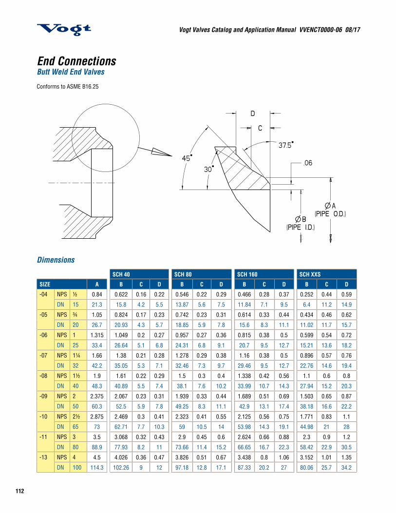
End ConnectionsButt Weld End Valves
Conforms to ASME B16.25
Dimensions
SCH 40 SCH 80 SCH 160 SCH XXS
SIZE A B C D B C D B C D B C D
-04 NPS ½ 0.84 0.622 0.16 0.22 0.546 0.22 0.29 0.466 0.28 0.37 0.252 0.44 0.59
DN 15 21.3 15.8 4.2 5.5 13.87 5.6 7.5 11.84 7.1 9.5 6.4 11.2 14.9
-05 NPS ¾ 1.05 0.824 0.17 0.23 0.742 0.23 0.31 0.614 0.33 0.44 0.434 0.46 0.62
DN 20 26.7 20.93 4.3 5.7 18.85 5.9 7.8 15.6 8.3 11.1 11.02 11.7 15.7
-06 NPS 1 1.315 1.049 0.2 0.27 0.957 0.27 0.36 0.815 0.38 0.5 0.599 0.54 0.72
DN 25 33.4 26.64 5.1 6.8 24.31 6.8 9.1 20.7 9.5 12.7 15.21 13.6 18.2
-07 NPS 1¼ 1.66 1.38 0.21 0.28 1.278 0.29 0.38 1.16 0.38 0.5 0.896 0.57 0.76
DN 32 42.2 35.05 5.3 7.1 32.46 7.3 9.7 29.46 9.5 12.7 22.76 14.6 19.4
-08 NPS 1½ 1.9 1.61 0.22 0.29 1.5 0.3 0.4 1.338 0.42 0.56 1.1 0.6 0.8
DN 40 48.3 40.89 5.5 7.4 38.1 7.6 10.2 33.99 10.7 14.3 27.94 15.2 20.3
-09 NPS 2 2.375 2.067 0.23 0.31 1.939 0.33 0.44 1.689 0.51 0.69 1.503 0.65 0.87
DN 50 60.3 52.5 5.9 7.8 49.25 8.3 11.1 42.9 13.1 17.4 38.18 16.6 22.2
-10 NPS 2½ 2.875 2.469 0.3 0.41 2.323 0.41 0.55 2.125 0.56 0.75 1.771 0.83 1.1
DN 65 73 62.71 7.7 10.3 59 10.5 14 53.98 14.3 19.1 44.98 21 28
-11 NPS 3 3.5 3.068 0.32 0.43 2.9 0.45 0.6 2.624 0.66 0.88 2.3 0.9 1.2
DN 80 88.9 77.93 8.2 11 73.66 11.4 15.2 66.65 16.7 22.3 58.42 22.9 30.5
-13 NPS 4 4.5 4.026 0.36 0.47 3.826 0.51 0.67 3.438 0.8 1.06 3.152 1.01 1.35
DN 100 114.3 102.26 9 12 97.18 12.8 17.1 87.33 20.2 27 80.06 25.7 34.2
113
Vogt Valves Catalog and Application Manual VVENCT0000-06 08/17
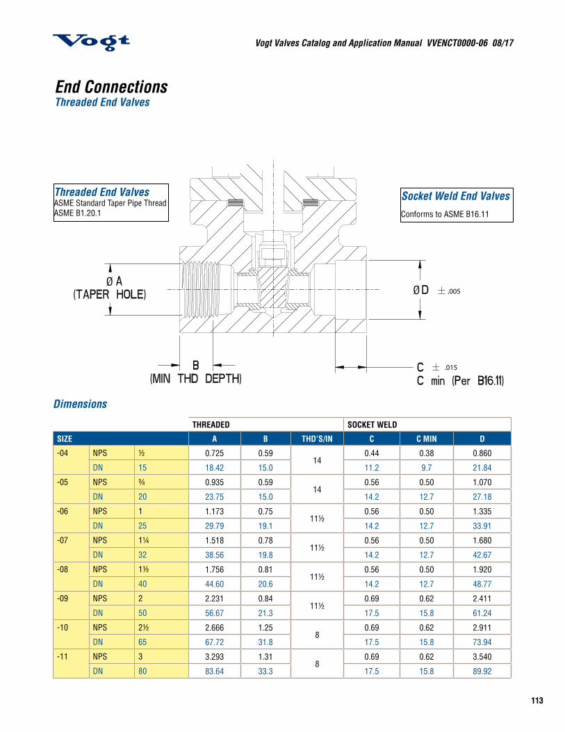
End ConnectionsThreaded End Valves
Dimensions
THREADED SOCKET WELD
SIZE A B THD’S/IN C C MIN D
-04 NPS ½ 0.725 0.5914
0.44 0.38 0.860
DN 15 18.42 15.0 11.2 9.7 21.84
-05 NPS ¾ 0.935 0.5914
0.56 0.50 1.070
DN 20 23.75 15.0 14.2 12.7 27.18
-06 NPS 1 1.173 0.7511½
0.56 0.50 1.335
DN 25 29.79 19.1 14.2 12.7 33.91
-07 NPS 1¼ 1.518 0.7811½
0.56 0.50 1.680
DN 32 38.56 19.8 14.2 12.7 42.67
-08 NPS 1½ 1.756 0.8111½
0.56 0.50 1.920
DN 40 44.60 20.6 14.2 12.7 48.77
-09 NPS 2 2.231 0.8411½
0.69 0.62 2.411
DN 50 56.67 21.3 17.5 15.8 61.24
-10 NPS 2½ 2.666 1.258
0.69 0.62 2.911
DN 65 67.72 31.8 17.5 15.8 73.94
-11 NPS 3 3.293 1.318
0.69 0.62 3.540
DN 80 83.64 33.3 17.5 15.8 89.92
Socket Weld End ValvesConforms to ASME B16.11
Threaded End ValvesASME Standard Taper Pipe ThreadASME B1.20.1
.005
.015
ØØ
Vogt Valves Catalog and Application Manual VVENCT0000-06 08/17
114
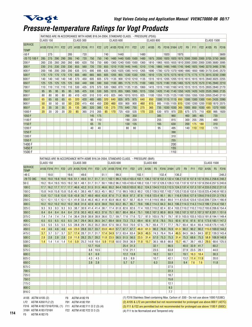
(1) F316 Stainless Steel containing Max. Carbon of .030 - Do not use above 1000 F(538C)(2) A105 & LF2 are permitted but not recommended for prolonged use above 800 F (427C)(3) F11 & F22 are permitted but not recommended for prolonged use above 1100 F (593C)(4) F11 to be Normalized and Tempered only
Pressure-temperature Ratings for Vogt Products RATINGS ARE IN ACCORDANCE WITH ASME B16.34-2004, STANDARD CLASS. - PRESSURE (PSIG)CLASS 150 CLASS 300 CLASS 600 CLASS 800 CLASS 1500
SERVICE
TEMPA105 F316 F11 F22 LF2 A105 F316 F11 F22 LF2 A105 F316 F11 F22 LF2 A105 F5 F316 316H LF2 F9 F11 F22 A105 F5 F316
-50 F 275 285 720 740 1440 1480 1920 1975 3600-20 TO 100 F 285 275 290 290 285 740 720 750 750 740 1480 1440 1500 1500 1480 1975 2000 1920 1920 1975 2000 2000 2000 3705 3750 3600200 F 260 235 260 260 260 680 620 750 750 680 1360 1240 1500 1500 1360 1810 1965 1655 1655 1810 2000 2000 2000 3395 3680 3095300 F 230 215 230 230 230 655 560 720 720 655 1310 1120 1445 1445 1310 1745 1865 1495 1495 1745 1940 1925 1940 3270 3495 2795400 F 200 195 200 200 200 635 515 695 695 635 1265 1025 1385 1410 1265 1690 1780 1370 1370 1690 1880 1850 1880 3170 3345 2570500 F 170 170 170 170 170 605 480 665 665 605 1205 955 1330 1330 1205 1610 1725 1275 1275 1610 1775 1775 1775 3015 3230 2390600 F 140 140 140 140 140 570 450 605 605 570 1135 900 1210 1210 1135 1515 1615 1205 1205 1515 1615 1615 1615 2840 3025 2255650 F 125 125 125 125 125 550 440 590 590 550 1100 885 1175 1175 1100 1465 1570 1180 1185 1465 1570 1570 1570 2745 2940 2210700 F 110 110 110 110 110 530 435 570 570 530 1060 870 1135 1135 1060 1415 1515 1160 1160 1415 1515 1515 1515 2655 2840 2170750 F 95 95 95 95 95 505 425 530 530 505 1015 855 1065 1065 1015 1350 1420 1140 1140 1350 1420 1420 1420 2535 2660 2135800 F 80 80 80 80 80 410 420 510 510 410 825 845 1015 1015 825 1100 1355 1125 1125 1100 1355 1355 1355 2055 2540 2110850 F 65 65 65 65 65 320 420 485 485 320 640 835 975 975 640 850 1300 1115 1115 850 1300 1300 1300 1595 2435 2090900 F 50 50 50 50 50 230 415 450 450 230 460 830 900 900 460 615 995 1105 1105 615 1200 1200 1200 1150 1870 2075950 F 35 35 35 35 35 135 385 320 385 135 275 775 640 755 275 365 735 1030 1030 365 1005 850 1030 685 1370 19301000 F 20 20 20 20 20 85 365 215 265 85 170 725 430 535 170 225 530 970 970 225 675 575 710 430 995 18201050 F 145 175 290 350 385 960 460 385 465 7201100 F 95 110 190 220 255 815 300 255 295 4801150 F 65 70 130 135 165 630 200 175 180 3101200 F 40 40 80 80 95 495 140 110 110 1701250 F 3901300 F 3101350 F 2551400 F 2001450 F 1551500 F 110
RATINGS ARE IN ACCORDANCE WITH ASME B16.34-2004, STANDARD CLASS. - PRESSURE (BAR)CLASS 150 CLASS 300 CLASS 600 CLASS 800 CLASS 1500
SERVICE TEMP A105 F316 F11 F22 LF2 A105 F316 F11 F22 LF2 A105 F316 F11 F22 LF2 A105 F5 F316 316H LF2 F9 F11 F22 A105 F5 F316
-46 C 19.0 19.6 49.6 51.1 99.3 102.1 132.4 136.2 248.2-29 TO 38C 19.6 19.0 19.8 19.8 19.6 51.1 49.6 51.7 51.7 51.1 102.1 99.3 103.4 103.4 102.1 136.2 137.9 132.4 132.4 136.2 137.9 137.9 137.9 255.3 258.6 248.250 C 19.2 18.4 19.5 19.5 19.2 50.1 48.1 51.7 51.7 50.1 100.2 96.2 103.4 103.4 100.2 133.7 137.3 128.3 128.3 133.7 137.9 137.9 137.9 250.6 257.5 240.6100 C 17.7 16.2 17.7 17.7 17.7 46.6 42.2 51.5 51.5 46.6 93.2 84.4 103.0 103.0 93.2 124.3 134.5 112.5 112.5 124.3 137.4 137.3 137.4 233.0 252.2 211.0150 C 15.8 14.8 15.8 15.8 15.8 45.1 38.5 49.7 50.3 45.1 90.2 77.0 99.5 100.3 90.2 120.2 128.5 102.7 102.7 120.2 133.8 132.6 133.8 225.4 240.9 192.5200 C 13.8 13.7 13.8 13.8 13.8 43.8 35.7 48.0 48.6 43.8 87.6 71.3 95.9 97.2 87.6 116.8 123.4 95.1 95.1 116.8 129.6 127.9 129.6 219.0 231.3 178.3250 C 12.1 12.1 12.1 12.1 12.1 41.9 33.4 46.3 46.3 41.9 83.9 66.8 92.7 92.7 83.9 111.8 119.5 89.0 89.0 111.8 123.6 123.6 123.6 209.7 224.1 166.9300 C 10.2 10.2 10.2 10.2 10.2 39.8 31.6 42.9 42.9 39.8 79.6 63.2 85.7 85.7 79.6 106.2 114.3 84.3 84.3 106.2 114.3 114.3 114.3 199.1 214.4 158.1325 C 9.3 9.3 9.3 9.3 9.3 38.7 30.9 41.4 41.4 38.7 77.4 61.8 82.6 82.6 77.4 103.2 110.2 82.4 82.4 103.2 110.2 110.2 110.2 193.6 206.6 154.4350 C 8.4 8.4 8.4 8.4 8.4 37.6 30.3 40.3 40.3 37.6 75.1 60.7 80.4 80.4 75.1 100.2 107.3 80.9 80.9 100.2 107.3 107.3 107.3 187.8 201.1 151.6375 C 7.4 7.4 7.4 7.4 7.4 36.4 29.9 38.9 38.9 36.6 72.7 59.7 77.6 77.6 72.7 97.0 103.5 79.7 79.7 97.0 103.5 103.5 103.5 181.8 194.1 149.4400 C 6.5 6.5 6.5 6.5 6.5 34.7 29.4 36.5 36.5 34.7 69.4 58.9 73.3 73.3 69.4 92.6 97.6 78.5 78.5 92.6 97.6 97.6 97.6 173.6 183.1 147.2425 C 5.5 5.5 5.5 5.5 5.5 28.8 29.1 35.2 35.2 28.8 57.5 58.3 70.0 70.0 57.5 76.7 93.4 77.7 77.7 76.7 93.4 93.4 93.4 143.8 175.1 145.7450 C 4.6 4.6 4.6 4.6 4.6 23.0 28.8 33.7 33.7 23.0 46.0 57.7 67.7 67.7 46.0 61.3 90.2 76.9 76.9 61.3 90.2 90.2 90.2 115.0 169.0 144.2475 C 3.7 3.7 3.7 3.7 3.7 17.4 28.7 31.7 31.7 17.4 34.9 57.3 63.4 63.4 34.9 46.5 74.3 76.4 76.4 46.5 84.5 84.5 84.5 87.2 139.3 143.4500 C 2.8 2.8 2.8 2.8 2.8 11.8 28.2 25.7 28.2 11.8 23.5 56.5 51.5 56.5 23.5 31.4 57.0 75.3 75.3 31.4 75.3 68.6 75.3 58.8 106.9 140.9538 C 1.4 1.4 1.4 1.4 1.4 5.9 25.2 14.9 18.4 5.9 11.8 50.0 29.8 36.9 11.8 15.7 36.5 66.8 66.8 15.7 46.7 39.7 49.2 29.5 68.6 125.5550 C 12.7 15.6 25.4 31.3 32.1 66.5 40.0 33.9 41.7 60.2575 C 8.8 10.5 17.6 21.1 23.5 63.8 27.9 23.5 28.1 44.0600 C 6.1 6.9 12.2 13.8 16.2 53.1 19.1 16.3 18.4 30.3625 C 4.3 4.5 8.5 8.9 10.7 42.1 13.2 11.4 11.9 20.0650 C 2.8 2.8 5.7 5.7 6.3 33.8 9.4 7.6 7.6 11.8675 C 27.5700 C 22.3725 C 18.7750 C 15.6775 C 12.1800 C 9.3816 C 7.7
A105 ASTM A105 (2)LF2 ASTM A350 FL2 (2)F316 ASTM A182 F316/F316L (1)316H ASTM A183 F316HF5 ASTM A182 F5
F9 ASTM A182 F9F91 ASTM A182 F91F11 ASTM A182 F11 Cl 2 (3) (4)F22 ASTM A182 F22 Cl 3 (3)

115
Vogt Valves Catalog and Application Manual VVENCT0000-06 08/17
Pressure-temperature Ratings for Vogt ProductsSTANDARD CLASS. - PRESSURE RATINGS ARE IN ACCORDANCE WITH ASME B16.34-2004, LIMITED CLASS. - PRESSURE (PSIG)CLASS 1500 CLASS 800 LTD CLASS 1500 LTD CLASS 1690 LTD CLASS 2500 LTD CLASS 2680 LTD316H LF2 F9 F11 F22 SERVICE
TEMP A105 F11 F22 F91 A105 F11 F22 F91 A105 F11 F22 F91 A105 F11 F22 F91 A105 F11 F22 F91
3705 -50 F3600 3705 3750 3750 3750 -20 TO 100 F 2000 2000 2000 2000 3750 3750 3750 3750 4225 4225 4225 4225 6250 6250 6250 6250 6700 6700 6700 67003095 3395 3750 3750 3750 200 F 2000 2000 2000 2000 3750 3750 3750 3750 4225 4225 4225 4225 6250 6250 6250 6250 6700 6700 6700 67002795 3270 3640 3610 3640 300 F 1975 2000 1975 2000 3700 3750 3695 3750 4170 4225 4165 4225 6170 6250 6160 6250 6615 6700 6605 67002570 3170 3530 3465 3530 400 F 1955 2000 1940 2000 3665 3750 3640 3750 4130 4225 4100 4225 6105 6250 6065 6250 6545 6700 6500 67002390 3015 3325 3325 3325 500 F 1955 2000 1935 2000 3665 3750 3620 3750 4130 4225 4080 4225 6105 6250 6035 6250 6545 6700 6470 67002255 2840 3025 3025 3025 600 F 1955 2000 1925 2000 3665 3750 3605 3750 4130 4225 4060 4225 6105 6250 6010 6250 6545 6700 6440 67002210 2745 2940 2940 2940 650 F 1905 2000 1905 2000 3575 3750 3580 3750 4030 4225 4035 4225 5960 6250 5965 6250 6390 6700 6395 67002170 2655 2840 2840 2840 700 F 1945 1955 1885 1955 3455 3665 3535 3665 3895 4130 3985 4130 5760 6110 5895 6110 6175 6550 6320 65502135 2535 2660 2660 2660 750 F 1695 1945 1885 1945 3170 3645 3535 3645 3570 4105 3985 4105 5285 6070 5895 6070 5665 6505 6320 65102110 2055 2540 2540 2540 800 F 1375 1920 1885 1920 2570 3600 3535 3600 2895 4055 3985 4055 4285 6000 5895 6000 4595 6430 6320 64302090 1595 2435 2435 2435 850 F 1060 1805 1805 1805 1996 3385 3385 3385 2245 3815 3815 3815 3320 5645 5645 5645 3560 6050 6050 60502075 1150 2245 2245 2245 900 F 765 1565 1600 1600 1435 2935 3000 3000 1615 3305 3380 3380 2395 4895 5000 5000 2565 5245 5360 63601930 685 1885 1595 1930 950 F 465 1075 1275 1275 875 2040 2410 2410 990 2305 2725 2725 1485 3445 4075 4075 1595 3700 4380 43801820 430 1270 1080 1335 1000 F 295 745 925 1160 570 1445 1785 2250 650 1640 2030 2555 1000 2520 3120 3925 1085 2725 3375 42451800 855 720 875 1050 F 495 600 1160 960 1170 2250 1095 1330 2555 1680 2040 3925 1815 2205 42451525 565 480 550 1100 F 330 375 1040 640 730 2015 730 835 2290 1120 1280 3520 1210 1385 38101185 375 325 345 1150 F 225 235 765 435 460 1490 495 520 1695 760 800 2600 825 865 2810925 255 205 205 1200 F 145 145 495 275 275 960 310 310 1095 480 480 1680 520 520 1815735 1250 F585 1300 F480 1350 F380 1400 F290 1450 F205 1500 F
STANDARD CLASS. - PRES-SURE
RATINGS ARE IN ACCORDANCE WITH ASME B16.34-2004, LIMITED CLASS. - PRESSURE (BAR)
CLASS 1500 CLASS 800 LTD CLASS 1500 LTD CLASS 1690 LTD CLASS 2500 LTD CLASS 2680 LTD316H LF2 F9 F11 F22 SERVICE
TEMP A105 F11 F22 F91 A105 F11 F22 F91 A105 F11 F22 F91 A105 F11 F22 F91 A105 F11 F22 F91
255.3 -46 C248.2 255.3 258.6 258.6 258.6 -29 TO 38C 137.9 137.9 137.9 137.9 258.6 258.6 258.6 258.6 291.3 291.3 291.3 291.3 430.9 430.9 430.9 430.9 461.9 461.9 461.9 461.9240.6 250.6 258.6 258.6 258.6 50 C 137.9 137.9 137.9 137.9 258.6 258.6 258.6 258.6 291.3 291.3 291.3 291.3 430.9 430.9 430.9 430.9 461.9 461.9 461.9 461.9211.0 233.0 257.6 257.4 257.6 100 C 137.7 137.9 137.7 137.9 258.2 258.6 258.1 258.6 290.9 291.3 290.8 291.3 430.9 430.9 430.2 430.9 461.3 461.9 461.2 461.9192.5 225.4 250.8 248.7 250.9 150 C 136.1 137.9 135.9 137.9 255.2 258.6 254.8 258.6 287.5 291.3 287.1 291.3 425.3 430.9 424.6 430.9 455.9 461.9 455.2 461.9178.3 219.0 243.4 239.8 243.4 200 C 134.8 137.9 133.9 137.9 252.9 258.6 251.1 258.6 284.9 291.3 282.9 291.3 421.4 430.9 418.5 430.9 451.7 461.9 448.6 461.9166.9 209.7 231.8 231.8 231.8 250 C 134.8 137.9 133.3 137.9 252.6 258.6 249.9 258.6 284.6 291.3 281.6 291.3 421.1 430.9 416.5 430.9 451.4 461.9 446.5 461.9158.1 199.1 214.4 214.4 214.4 300 C 134.8 137.9 132.7 137.9 252.6 258.6 248.9 258.6 284.6 291.3 280.4 291.3 421.1 430.9 414.8 430.9 451.4 461.9 444.7 461.9154.4 193.6 206.6 206.6 206.6 325 C 133.6 137.9 132.3 137.9 250.6 258.6 248.0 258.6 282.3 291.3 279.4 291.3 417.6 430.9 413.3 430.9 447.7 461.9 443.1 461.9151.6 187.8 201.1 201.1 201.1 350 C 130.4 137.1 131.2 137.1 244.6 257.1 246.0 257.1 275.6 289.7 277.2 289.7 407.6 428.6 410.0 428.6 436.9 459.5 439.5 459.5149.4 181.8 194.1 194.1 194.1 375 C 125.6 134.7 130.0 134.7 235.5 252.5 243.8 252.5 265.3 284.5 274.7 284.5 392.5 420.9 406.3 420.9 420.8 451.2 435.6 451.2147.2 173.6 183.1 183.1 183.1 400 C 115.7 133.9 130.0 133.9 217.0 251.2 243.8 251.2 244.5 282.9 274.7 282.9 361.7 418.3 406.3 418.3 387.7 448.4 435.6 448.4145.7 143.8 175.1 175.1 175.1 425 C 95.9 132.4 130.0 132.4 179.8 248.2 248.3 248.2 202.6 279.6 274.7 279.6 299.6 413.7 406.3 413.7 321.2 443.5 435.6 443.5144.2 115.0 169.0 169.0 169.1 450 C 76.7 125.7 125.7 125.7 143.8 235.8 235.8 235.8 162.0 265.7 265.7 265.7 239.6 393.1 393.1 393.1 256.9 421.4 421.4 421.4143.4 87.2 158.2 158.2 158.2 475 C 58.1 114.0 114.0 114.0 109.0 213.7 213.7 213.7 122.8 240.8 240.8 240.8 181.6 356.3 356.3 356.3 194.7 382.0 382.0 382.0140.9 58.8 140.9 128.6 140.9 500 C 39.2 85.8 95.2 95.2 73.5 160.8 178.6 178.6 82.8 182.2 201.2 201.2 122.4 268.0 297.5 279.5 131.2 287.3 318.9 318.9125.5 29.5 87.5 74.5 92.2 538 C 20.4 51.4 63.6 80.0 39.4 99.5 123.1 155.1 44.8 113.1 139.9 176.2 69.0 173.7 215.2 270.7 74.6 187.8 232.6 292.7124.9 75.0 63.5 78.2 550 C 43.9 53.9 80.0 84.9 104.4 155.1 96.5 118.7 176.2 148.3 182.3 270.7 160.3 197.2 292.7119.7 52.3 44.0 52.6 575 C 30.4 36.3 78.9 58.8 70.3 152.8 68.8 79.9 173.7 102.7 122.9 266.9 111.1 132.9 288.699.5 35.9 30.5 34.4 600 C 21.1 23.7 67.3 40.8 46.0 130.3 46.4 52.2 148.1 71.2 80.3 227.5 77.0 86.8 246.079.1 24.8 21.3 22.3 625 C 14.7 15.4 50.4 28.4 29.8 97.6 32.3 33.9 110.9 49.7 52.1 170.4 53.8 56.3 184.263.3 17.7 14.2 14.2 650 C 9.8 9.8 34.2 18.9 18.9 66.4 21.5 21.5 75.4 33.0 33.0 115.8 35.7 35.7 125.251.6 675 C41.9 700 C34.9 725 C29.3 750 C22.8 775 C17.4 800 C14.1 816 C
A105 ASTM A105 (2)LF2 ASTM A350 FL2 (2)F316 ASTM A182 F316/F316L (1)316H ASTM A183 F316HF5 ASTM A182 F5
F9 ASTM A182 F9F91 ASTM A182 F91F11 ASTM A182 F11 Cl 2 (3) (4)F22 ASTM A182 F22 Cl 3 (3)
(1) F316 Stainless Steel containing Max. Carbon of .030 - Do not use above 1000 F(538C)(2) A105 & LF2 are permitted but not recommended for prolonged use above 800 F (427C)(3) F11 & F22 are permitted but not recommended for prolonged use above 1100 F (593C)(4) F11 to be Normalized and Tempered only
Vogt Valves Catalog and Application Manual VVENCT0000-06 08/17
116
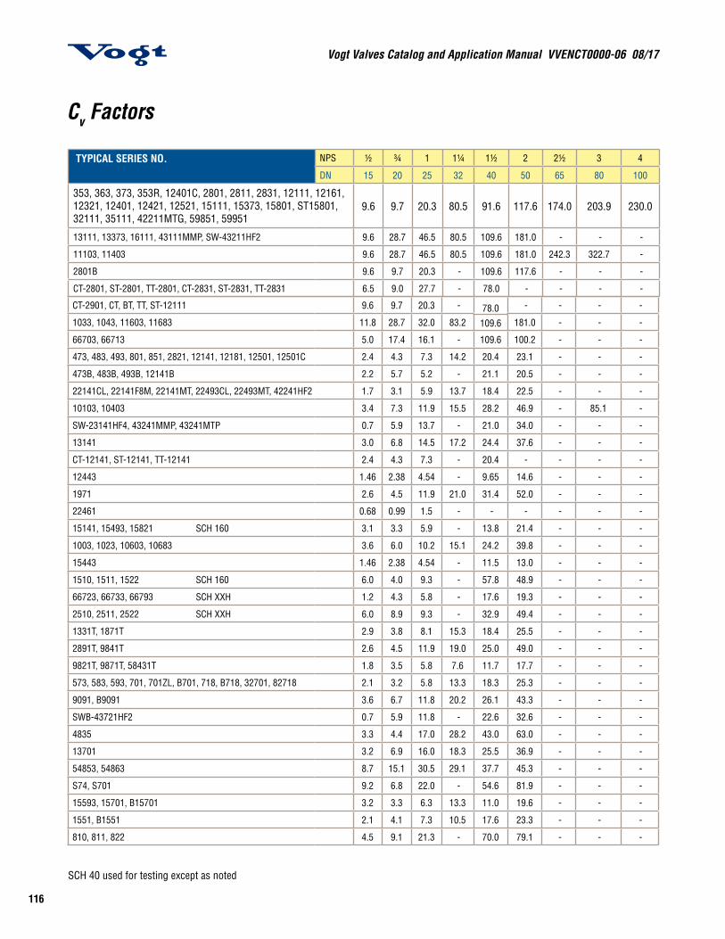
Cv Factors
TYPICAL SERIES NO. NPS ½ ¾ 1 1¼ 1½ 2 2½ 3 4
DN 15 20 25 32 40 50 65 80 100
353, 363, 373, 353R, 12401C, 2801, 2811, 2831, 12111, 12161, 12321, 12401, 12421, 12521, 15111, 15373, 15801, ST15801, 32111, 35111, 42211MTG, 59851, 59951
9.6 9.7 20.3 80.5 91.6 117.6 174.0 203.9 230.0
13111, 13373, 16111, 43111MMP, SW-43211HF2 9.6 28.7 46.5 80.5 109.6 181.0 - - -
11103, 11403 9.6 28.7 46.5 80.5 109.6 181.0 242.3 322.7 -
2801B 9.6 9.7 20.3 - 109.6 117.6 - - -
CT-2801, ST-2801, TT-2801, CT-2831, ST-2831, TT-2831 6.5 9.0 27.7 - 78.0 - - - -
SCH 40 used for testing except as noted
CT-2901, CT, BT, TT, ST-12111 9.6 9.7 20.3 - 78.0109.6
- - - -
1033, 1043, 11603, 11683 11.8 28.7 32.0 83.2 181.0 - - -
66703, 66713 5.0 17.4 16.1 - 109.6 100.2 - - -
473, 483, 493, 801, 851, 2821, 12141, 12181, 12501, 12501C 2.4 4.3 7.3 14.2 20.4 23.1 - - -
473B, 483B, 493B, 12141B 2.2 5.7 5.2 - 21.1 20.5 - - -
22141CL, 22141F8M, 22141MT, 22493CL, 22493MT, 42241HF2 1.7 3.1 5.9 13.7 18.4 22.5 - - -
10103, 10403 3.4 7.3 11.9 15.5 28.2 46.9 - 85.1 -
SW-23141HF4, 43241MMP, 43241MTP 0.7 5.9 13.7 - 21.0 34.0 - - -
13141 3.0 6.8 14.5 17.2 24.4 37.6 - - -
CT-12141, ST-12141, TT-12141 2.4 4.3 7.3 - 20.4 - - - -
12443 1.46 2.38 4.54 - 9.65 14.6 - - -
1971 2.6 4.5 11.9 21.0 31.4 52.0 - - -
22461 0.68 0.99 1.5 - - - - - -
15141, 15493, 15821 SCH 160 3.1 3.3 5.9 - 13.8 21.4 - - -
1003, 1023, 10603, 10683 3.6 6.0 10.2 15.1 24.2 39.8 - - -
15443 1.46 2.38 4.54 - 11.5 13.0 - - -
1510, 1511, 1522 SCH 160 6.0 4.0 9.3 - 57.8 48.9 - - -
66723, 66733, 66793 SCH XXH 1.2 4.3 5.8 - 17.6 19.3 - - -
2510, 2511, 2522 SCH XXH 6.0 8.9 9.3 - 32.9 49.4 - - -
1331T, 1871T 2.9 3.8 8.1 15.3 18.4 25.5 - - -
2891T, 9841T 2.6 4.5 11.9 19.0 25.0 49.0 - - -
9821T, 9871T, 58431T 1.8 3.5 5.8 7.6 11.7 17.7 - - -
573, 583, 593, 701, 701ZL, B701, 718, B718, 32701, 82718 2.1 3.2 5.8 13.3 18.3 25.3 - - -
9091, B9091 3.6 6.7 11.8 20.2 26.1 43.3 - - -
SWB-43721HF2 0.7 5.9 11.8 - 22.6 32.6 - - -
4835 3.3 4.4 17.0 28.2 43.0 63.0 - - -
13701 3.2 6.9 16.0 18.3 25.5 36.9 - - -
54853, 54863 8.7 15.1 30.5 29.1 37.7 45.3 - - -
S74, S701 9.2 6.8 22.0 - 54.6 81.9 - - -
15593, 15701, B15701 3.2 3.3 6.3 13.3 11.0 19.6 - - -
1551, B1551 2.1 4.1 7.3 10.5 17.6 23.3 - - -
810, 811, 822 4.5 9.1 21.3 - 70.0 79.1 - - -
117
Vogt Valves Catalog and Application Manual VVENCT0000-06 08/17
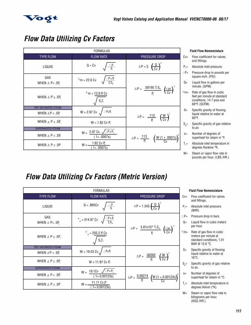
Flow Data Utilizing Cv Factors
Flow Data Utilizing Cv Factors (Metric Version)
FORMULAS
TYPE FLOW FLOW RATE PRESSURE DROP
LIQUID Q = Cv
GAS WHEN P< .5P1
WHEN P > .5P
DRY SATURATED STEAM
WHEN
SUPERHEATED STEAM
1
m = 22.6 Cvq ` x
T
q `m = 13.9 P Cv
S T
P < .5P1
WHEN P > .5P1
W = 2.97 Cv
W = 1.82 Cv P
WHEN P < .5P1
WHEN P > .5P
W = 2.97 Cv ( 1= .0007s)
W = 1.82 Cv P( 1= .0007s)
P = .00195 T S
Pm
Cv
.113
.113
P = S QCv( )(
( )
( )
( )
P =
P =
1
g1
1
g 1
x 1
1
x 1
1
2
1 g
1
2q `
P1
WCv
2
W (1 + .0007s)P1 Cv
2
Fluid Flow Nomenclature
Cv= Flow coefficient for valves and fittings.
P1= Absolute inlet pressure.
P= Pressure drop in pounds per square inch. (PSI)
Q= Liquid flow in gallons per minute. (GPM)
q`m= Rate of gas flow in cubic feet per minute at standard conditions, 14.7 psia and 60°F. (SCFM)
S= Specific gravity of flowing liquid relative to water at 60°F.
Sg= Specific gravity of gas relative to air.
s= Number of degrees of superheat for steam in °F.
T1= Absolute inlet temperature in degrees Rankine °R.
W= Steam or vapor flow rate in pounds per hour. (LBS./HR.)
FORMULAS
TYPE FLOW FLOW RATE PRESSURE DROP
LIQUID Q = .865Cv
GAS WHEN P< .5P1
WHEN P > .5P
DRY SATURATED STEAM
WHEN
SUPERHEATED STEAM
1
H = 414.97 Cvq ` x
T
q `H = 255.2 P Cv
S T
P < .5P1
WHEN P > .5P1
W = 19.53 Cv
W = 11.97 Cv P
WHEN P < .5P1
WHEN P > .5P
W = 19.1Cv ( 1= 0.00123s)
W = 11.71 Cv P( 1= 0.00123s)
P = 5.81x10⁻⁶ T S
Pm
Cv
.00262
0.00274
P = 1.34S QCv( )(
( )
( )
( )
P =
P =
1
g1
1
g 1
x 1
1
x 1
1
2
1 g
1
2q `
P1
WCv
2
W (1 + 0.00123s)P1 Cv
2
Fluid Flow Nomenclature
Cv= Flow coefficient for valves and fittings.
P1= Absolute inlet pressure. (BAR)
P= Pressure drop in bars.
Q= Liquid flow in cubic meters per hour
q`m= Rate of gas flow in cubic meters per minute at standard conditions, 1.01 BAR @ 15.6 °C
S= Specific gravity of flowing liquid relative to water at 16°C.
Sg= Specific gravity of gas relative to air.
s= Number of degrees of superheat for steam in °C.
T1= Absolute inlet temperature in degrees Kelvin (°K).
W= Steam or vapor flow rate in killograms per hour. (KGS./HR.)
Vogt Valves Catalog and Application Manual VVENCT0000-06 08/17
118
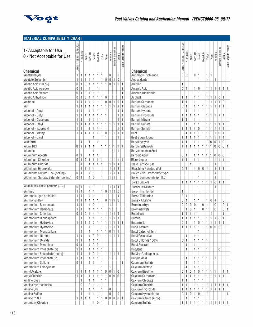
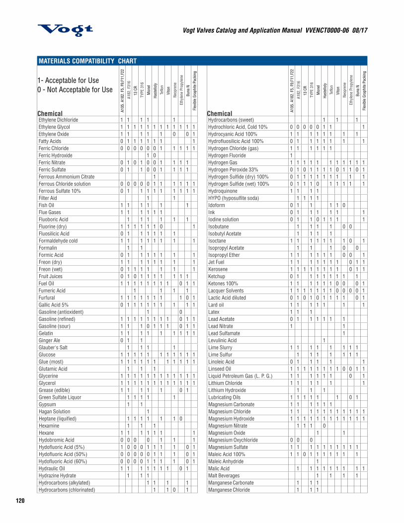
MATERIAL COMPATIBILITY CHART
1- Acceptable for Use 0 - Not Acceptable for Use
Chemical A105
. A18
2. F
5, F
9,F1
1,F2
2
A182
, F31
6
13 C
R
TYPE
316
Mon
el
Hast
ello
ly
Teflo
n
Vito
n
Neop
rene
Ethy
lene
Pro
pyle
ne
Buna
N
Flex
ible
Gra
phite
Pac
king
Chemical A105
. A18
2. F
5, F
9,F1
1,F2
2
A182
, F31
6
13 C
R
TYPE
316
Mon
el
Hast
ello
ly
Teflo
n
Vito
n
Neop
rene
Ethy
lene
Pro
pyle
ne
Buna
N
Flex
ible
Gra
phite
Pac
king
Acetaldehyde 1 1 1 1 1 1 1 0 0 Antimony Trichloride 0 0 0 1 1 1Acetate Solvents 1 1 1 1 1 1 0 0 1 0 Antioxidants 1 1 1Acetic Acid (100%) 0 1 0 1 1 1 1 1 0 1 0 1 Archlor 1Acetic Acid (crude) 0 1 1 1 1 Arsenic Acid 0 1 1 0 1 1 1 1 1 1Acetic Acid Vapors 0 1 0 1 1 1 1 Arsenic Trichloride 1 1Acetic Anhydride 0 1 0 1 1 1 1 0 1 Asphalt 1 1 1 1 1 1 1 0 1Acetone 1 1 1 1 1 1 1 0 0 1 0 1 Barium Carbonate 1 1 1 1 1 1 1 1 1 0Air 1 1 1 1 1 1 1 1 1 1 1 1 Barium Chloride 0 1 1 1 1 1 1 1 1 1Alcohol - Amyl 1 1 1 1 1 1 1 1 1 Barium Hydrate 1 1 1 1Alcohol - Butyl 1 1 1 1 1 1 1 1 1 1 Barium Hydroxide 1 1 1 1 1 1 1 1 1 1Alcohol - Diacetone 1 1 1 1 1 1 1 1 1 Barium Nitrate 1 1 1Alcohol - Ethyl 1 1 1 1 1 1 1 1 1 1 1 1 Barium Sulfate 1 1 1 1 1 1 1 1Alcohol - Isopropyl 1 1 1 1 1 1 1 1 1 Barium Sulfide 1 1 1 1 0 1 1 1 1 1Alcohol - Methyl 1 1 1 1 1 1 1 0 1 1 1 1 Beer 0 1 1 1 1 1 1 1 1 0 1Alcohol - Oleyl 1 1 1 Beet Sugar Liquor 1 1 1 1 1 1 1 1 1 1Alkaform 1 1 1 Benzaldehyde 1 1 1 1 1 0 0 1 0Alum 10% 0 1 1 1 1 1 1 1 1 1 1 Benzene(Benzol) 1 1 1 1 1 1 1 1 0 0 0 1Alumina 1 1 1 1 1 Benzensulfonic Acid 1 1Aluminum Acetate 0 1 1 1 1 Benzoic Acid 0 1 1 1 1 1 1 0 0 0Aluminum Chloride 0 1 0 1 1 1 1 1 1 1 1 Black Liquor 1 1 1 1 1 1 1 1 1Aluminum Fluoride 1 1 1 1 1 1 1 1 Blast Furnace Gas 1 1Aluminum Hydroxide 1 1 1 1 1 1 1 1 Bleaching Powder, Wet 0 1 1 0 0 1 1 1 1Aluminum Sulfate 10% (boiling) 0 1 1 1 1 1 1 1 Boiler Acid - Phosphate type 1 1Aluminum Sulfate, Saturate (boiling) 0 1 1 0 1 1 1 Boiler Compounds (ph 8.0) 1 1
Borax Liquors 1 1 1 1 1 1 1 1 0 1 1Aluminum Sulfate, Saturate (room) 0 1 1 1 1 1 1 1 Bordeaux Mixture 1 1Amines 1 1 1 1 1 0 1 1 0 Boron Trichloride 1Ammonia (gas or liquid) 1 1 1 1 1 1 1 Boron Triflouride 0 1 1Ammonia, Dry 1 1 1 1 1 1 0 1 1 0 Brine - Alkaline 0 1 1 1 1 0 1 0Ammonium Bicarbonate 1 1 1 0 1 1 Bromine(dry) 0 0 0 0 1 0 1 0 0 1Ammonium Carbonate 1 1 1 1 1 1 1 Bromine(wet) 1 0 1 0 1 0 0 1Ammonium Chloride 0 1 0 1 1 1 1 1 1 1 1 Butadiene 1 1 1 1 1 1 1Ammonium Diphosphate 1 1 1 1 1 1 1 1 Butane 1 1 1 1 1 1 1 1 0 1Ammonium Hydroxide 1 1 1 1 0 1 1 1 1 1 1 1 Buttermilk 0 1 1 0 1 1 1 1 1 1Ammonium Hydrozide 1 1 1 1 1 1 1 Butyl Acetate 1 1 1 1 1 1 1 0 0 0 0Ammonium Monosulfate 1 1 1 1 1 0 1 1 Butyl Catechol Tert 1Ammonium Nitrate 1 1 1 0 0 1 1 1 1 1 Butyl Cellusolve 1 1 1Ammonium Oxalate 1 1 1 1 1 Butyl Chloride 100% 0 1 1 1 1 1Ammonium Persulfate 0 1 1 0 0 Butyl Stearate 1 1Ammonium Phosphate(di) 1 1 1 1 1 1 Butylene 1 1 1 1 0Ammonium Phosphate(mono) 1 1 1 0 1 1 1 1 1 1 Butyl-p-Aminopheno 1Ammonium Phosphate(tri) 1 1 1 1 1 1 Butyric Acid 0 1 1 1 1 1 1Ammonium Sulfate 0 1 1 1 1 1 Cadmium Sulfate 1 1 1 1Ammonium Thiocyanate 1 1 Calcium Acetate 1 1 1Amyl Acetate 1 1 1 1 1 1 1 0 0 1 0 Calcium Bisulfite 0 1 0 1 0 1 1 1 1 1 1Amyl Chloride 1 1 1 1 1 1 1 0 0 0 Calcium Carbonate 1 1 1 1 1 1 1 1 1Aniline Dyes 1 1 1 1 1 Calcium Chlorate 1 1 1 1 1Aniline Hydrochloride 0 0 1 1 1 Calcium Chloride 1 1 1 1 1 1 1 1 1 1 1Aniline Oils 1 1 1 1 0 Calcium Hydroxide 1 1 1 1 1 1 1 1 1 1 1Aniline Sulfite 1 1 1 1 1 0 0 Calcium Hypochlorite 0 1 0 1 0 1 1 1Aniline to 80F 1 1 1 1 1 1 0 0 0 0 1 Calcium Nitrate (40%) 1 1 1Antimony Chloride 1 0 1 Calcium Sulfate 1 1 1 1 1 1 1 1 1 1 1 1
119
Vogt Valves Catalog and Application Manual VVENCT0000-06 08/17
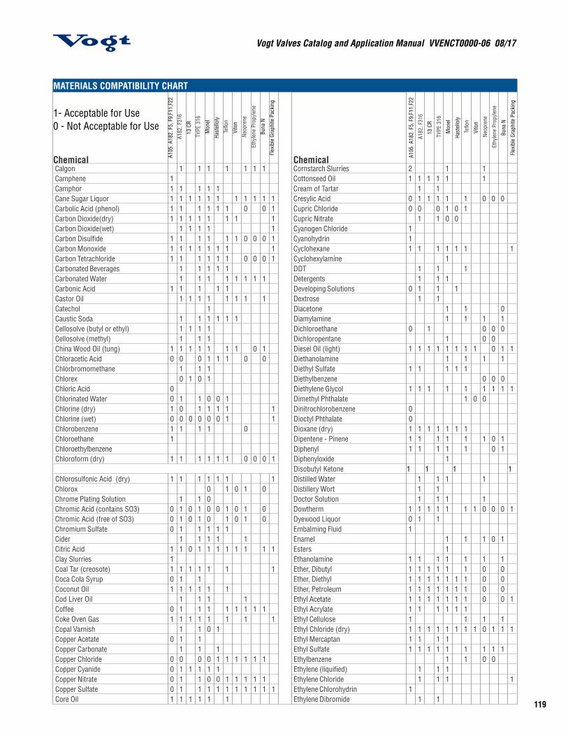
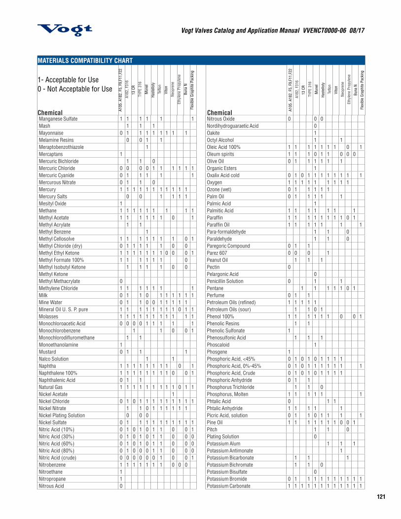
MATERIALS COMPATIBILITY CHART
1- Acceptable for Use 0 - Not Acceptable for Use
Chemical A105
. A18
2. F
5, F
9,F1
1,F2
2
A182
, F31
6
13 C
R
TYPE
316
Mon
el
Hast
ello
ly
Teflo
n
Vito
n
Neop
rene
Ethy
lene
Pro
pyle
ne
Buna
N
Flex
ible
Gra
phite
Pac
king
Chemical A105
. A18
2. F
5, F
9,F1
1,F2
2
A182
, F31
6
13 C
R
TYPE
316
Mon
el
Hast
ello
ly
Teflo
n
Vito
n
Neop
rene
Ethy
lene
Pro
pyle
ne
Buna
N
Flex
ible
Gra
phite
Pac
king
Calgon 1 1 1 1 1 1 1 Cornstarch Slurries 2 1 1Camphene 1 Cottonseed Oil 1 1 1 1 1 1Camphor 1 1 1 1 1 Cream of Tartar 1 1Cane Sugar Liquor 1 1 1 1 1 1 1 1 1 1 1 Cresylic Acid 0 1 1 1 1 1 0 0 0Carbolic Acid (phenol) 1 1 1 1 1 1 0 0 1 Cupric Chloride 0 0 0 1 0 1Carbon Dioxide(dry) 1 1 1 1 1 1 1 1 Cupric Nitrate 1 1 0 0Carbon Dioxide(wet) 1 1 1 1 1 Cyanogen Chloride 1Carbon Disulfide 1 1 1 1 1 1 0 0 0 1 Cyanohydrin 1Carbon Monoxide 1 1 1 1 1 1 1 1 Cyclohexane 1 1 1 1 1 1 1Carbon Tetrachloride 1 1 1 1 1 1 0 0 0 1 Cyclohexylamine 1Carbonated Beverages 1 1 1 1 1 DDT 1 1 1Carbonated Water 1 1 1 1 1 1 1 1 Detergents 1 1 1Carbonic Acid 1 1 1 1 1 Developing Solutions 0 1 1 1Castor Oil 1 1 1 1 1 1 1 1 Dextrose 1 1Catechol 1 Diacetone 1 1 0Caustic Soda 1 1 1 1 1 1 Diamylamine 1 1 1 1Cellosolve (butyl or ethyl) 1 1 1 1 Dichloroethane 0 1 0 0 0Cellosolve (methyl) 1 1 1 Dichloropentane 1 0 0China Wood Oil (tung) 1 1 1 1 1 1 1 0 1 Diesel Oil (light) 1 1 1 1 1 1 1 1 0 1 1Chloracetic Acid 0 0 0 1 1 1 0 0 Diethanolamine 1 1 1 1Chlorbromomethane 1 1 1 Diethyl Sulfate 1 1 1 1 1Chlorex 0 1 0 1 Diethylbenzene 0 0 0Chloric Acid 0 Diethylene Glycol 1 1 1 1 1 1 1 1 1Chlorinated Water 0 1 1 0 0 1 Dimethyl Phthalate 1 0 0Chlorine (dry) 1 0 1 1 1 1 1 Dinitrochlorobenzene 0Chlorine (wet) 0 0 0 0 0 0 1 1 Dioctyl Phthalate 0Chlorobenzene 1 1 1 1 0 Dioxane (dry) 1 1 1 1 1 1 1Chloroethane 1 Dipentene - Pinene 1 1 1 1 1 1 0 1Chloroethylbenzene Diphenyl 1 1 1 1 1 0 1Chloroform (dry) 1 1 1 1 1 1 0 0 0 1 Diphenyloxide 1
Disobutyl Ketone 1 1 1 1Chlorosulfonic Acid (dry) 1 1 1 1 1 1 1 Distilled Water 1 1 1 1Chlorox 0 1 0 1 0 Distillery Wort 1 1Chrome Plating Solution 1 1 0 Doctor Solution 1 1 1 1Chromic Acid (contains SO3) 0 1 0 1 0 0 1 0 1 0 Dowtherm 1 1 1 1 1 1 1 0 0 0 1Chromic Acid (free of SO3) 0 1 0 1 0 1 0 1 0 Dyewood Liquor 0 1 1Chromium Sulfate 0 1 1 1 1 1 Embalming Fluid 1Cider 1 1 1 1 1 Enamel 1 1 1 0 1Citric Acid 1 1 0 1 1 1 1 1 1 1 1 Esters 1Clay Slurries 1 Ethanolamine 1 1 1 1 1 1 1Coal Tar (creosote) 1 1 1 1 1 1 1 Ether, Dibutyl 1 1 1 1 1 1 0 0Coca Cola Syrup 0 1 1 Ether, Diethyl 1 1 1 1 1 1 1 0 0Coconut Oil 1 1 1 1 1 1 Ether, Petroleum 1 1 1 1 1 1 1 0 0Cod Liver Oil 1 1 1 1 Ethyl Acetate 1 1 1 1 1 1 1 0 0 1Coffee 0 1 1 1 1 1 1 1 1 Ethyl Acrylate 1 1 1 1 1 1Coke Oven Gas 1 1 1 1 1 1 1 1 Ethyl Cellulose 1 1 1 1Copal Varnish 1 1 0 1 Ethyl Chloride (dry) 1 1 1 1 1 1 1 1 0 1 1 1Copper Acetate 0 1 1 Ethyl Mercaptan 1 1 1 1Copper Carbonate 1 1 1 Ethyl Sulfate 1 1 1 1 1 1 1 1 1Copper Chloride 0 0 0 0 1 1 1 1 1 1 Ethylbenzene 1 1 0 0Copper Cyanide 0 1 1 1 1 1 Ethylene (liquified) 1 1 1Copper Nitrate 0 1 1 0 0 1 1 1 1 1 Ethylene Chloride 1 1 1 1Copper Sulfate 0 1 1 1 1 1 1 1 1 1 1 Ethylene Chlorohydrin 1Core Oil 1 1 1 1 1 1 Ethylene Dibromide 1 1
Vogt Valves Catalog and Application Manual VVENCT0000-06 08/17
120
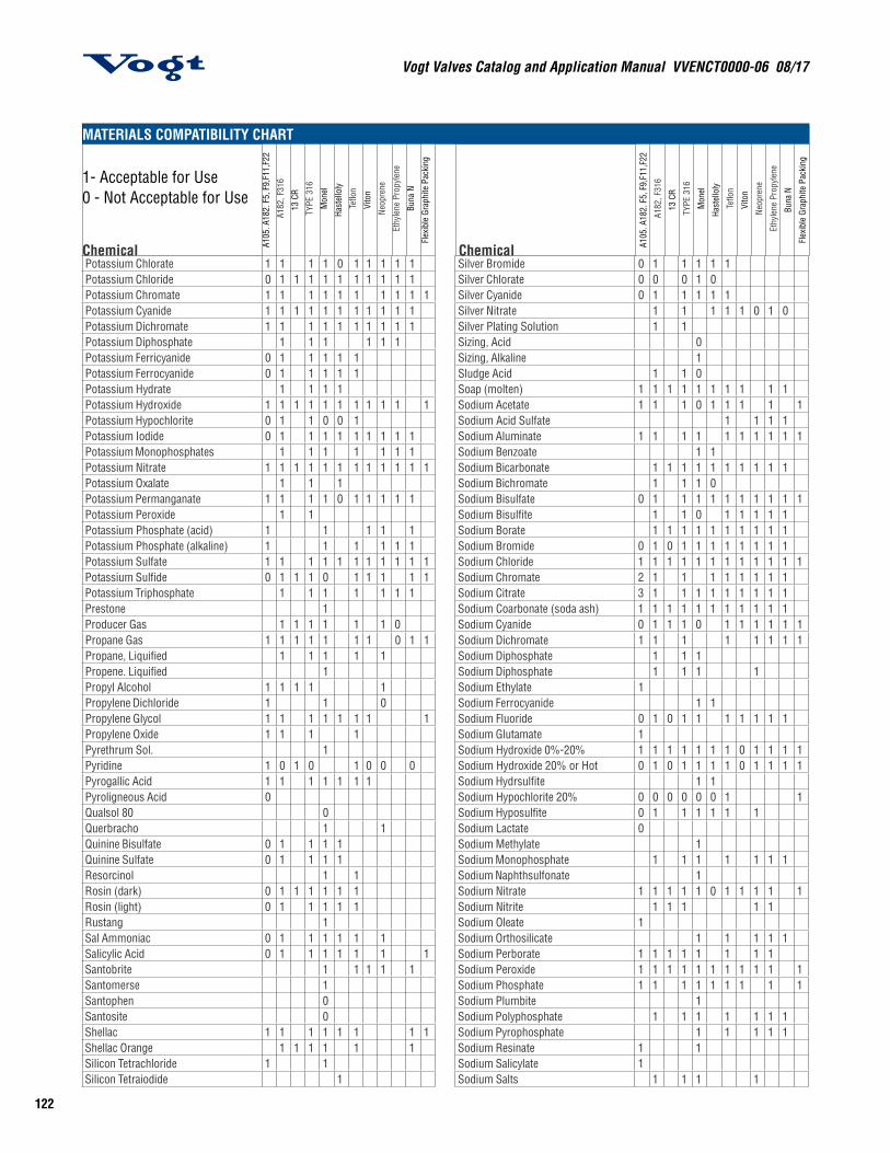
MATERIALS COMPATIBILITY CHART
1- Acceptable for Use 0 - Not Acceptable for Use
Chemical A105
. A18
2. F
5, F
9,F1
1,F2
2
A182
, F31
6
13 C
R
TYPE
316
Mon
el
Hast
ello
ly
Teflo
n
Vito
n
Neop
rene
Ethy
lene
Pro
pyle
ne
Buna
N
Flex
ible
Gra
phite
Pac
king
Chemical A105
. A18
2. F
5, F
9,F1
1,F2
2
A182
, F31
6
13 C
R
TYPE
316
Mon
el
Hast
ello
ly
Teflo
n
Vito
n
Neop
rene
Ethy
lene
Pro
pyle
ne
Buna
N
Flex
ible
Gra
phite
Pac
king
Ethylene Dichloride 1 1 1 1 1 Hydrocarbons (sweet) 1 1 1Ethylene Glycol 1 1 1 1 1 1 1 1 1 1 1 1 Hydrochloric Acid, Cold 10% 0 0 0 0 0 1 1 1Ethylene Oxide 1 1 1 1 1 0 0 1 Hydrocyanic Acid 100% 1 1 1 1 1 1 1 1Fatty Acids 0 1 1 1 1 1 1 1 Hydrofluosilicic Acid 100% 0 1 1 1 1 1 1 1Ferric Chloride 0 0 0 0 0 0 1 1 1 1 1 Hydrogen Chloride (gas) 1 1 1 1 1 1Ferric Hydroxide 1 0 Hydrogen Fluoride 1Ferric Nitrate 0 1 0 1 0 0 1 1 1 1 Hydrogen Gas 1 1 1 1 1 1 1 1 1 1 1Ferric Sulfate 0 1 1 0 0 1 1 1 1 Hydrogen Peroxide 33% 0 1 0 1 1 1 1 0 1 1 0 1Ferrous Ammonium Citrate 1 Hydrogen Sulfide (dry) 100% 0 1 1 1 1 1 1 1 1 1Ferrous Chloride solution 0 0 0 0 0 1 1 1 1 1 1 Hydrogen Sulfide (wet) 100% 0 1 1 1 0 1 1 1 1 1Ferrous Sulfate 10% 0 1 1 1 1 1 1 1 1 1 Hydroquinone 1 1 1 1Filter Aid 1 1 HYPO (hyposulfite soda) 1 1 1 1Fish Oil 1 1 1 1 1 1 Idoform 0 1 1 1 1 0Flue Gases 1 1 1 1 1 1 Ink 0 1 1 1 1 1 1Fluoboric Acid 1 1 1 1 1 1 Iodine solution 0 1 1 0 1 1 1 1Fluorine (dry) 1 1 1 1 1 1 0 1 Isobutane 1 1 1 1 0 0Fluosilicic Acid 0 1 1 1 1 1 1 Isobutyl Acetate 1 1 1 1Formaldehyde cold 1 1 1 1 1 1 1 1 Isoctane 1 1 1 1 1 1 1 0 1Formalin 1 1 Isopropyl Acetate 1 1 1 0 0Formic Acid 0 1 1 1 1 1 1 1 Isopropyl Ether 1 1 1 1 1 1 0 0 1Freon (dry) 1 1 1 1 1 1 1 1 Jet Fuel 1 1 1 1 1 1 1 0 1 1Freon (wet) 0 1 1 1 1 1 1 1 Kerosene 1 1 1 1 1 1 1 1 0 1 1Fruit Juices 0 1 0 1 1 1 1 1 1 1 Ketchup 0 1 1 1 1 1 1 1 1Fuel Oil 1 1 1 1 1 1 1 1 0 1 1 Ketones 100% 1 1 1 1 1 1 0 0 0 1Fumeric Acid 1 1 1 1 Lacquer Solvents 1 1 1 1 1 1 1 0 0 0 0 1Furfural 1 1 1 1 1 1 1 1 0 1 Lactic Acid diluted 0 1 0 1 0 1 1 1 1 0 1Gallic Acid 5% 0 1 1 1 1 1 1 1 1 1 Lard oil 1 1 1 1 1 1 1Gasoline (antioxident) 1 0 Latex 1 1 1Gasoline (refined) 1 1 1 1 1 1 1 1 0 1 1 Lead Acetate 0 1 1 1 1 1 1Gasoline (sour) 1 1 1 0 1 1 1 0 1 1 Lead Nitrate 1 1Gelatin 1 1 1 1 1 1 1 1 1 Lead Sulfamate 1Ginger Ale 0 1 1 Levulinic Acid 1Glauber's Salt 1 1 1 1 Lime Slurry 1 1 1 1 1 1 1 1Glucose 1 1 1 1 1 1 1 1 1 1 1 Lime Sulfur 1 1 1 1 1 1 1Glue (most) 1 1 1 1 1 1 1 1 1 1 1 Linoleic Acid 0 1 1 1 1 1Glutamic Acid 1 1 1 Linseed Oil 1 1 1 1 1 1 1 1 0 0 1 1Glycerine 1 1 1 1 1 1 1 1 1 1 1 1 Liquid Petroleum Gas (L. P. G.) 1 1 1 1 1 1 0 1Glycerol 1 1 1 1 1 1 1 1 1 1 1 1 Lithium Chloride 1 1 1 1 1 1Grease (edible) 1 1 1 1 1 0 1 Lithium Hydroxide 1 1 1Green Sulfate Liquor 1 1 1 1 1 Lubricating Oils 1 1 1 1 1 1 0 1Gypsum 1 1 Magnesium Carbonate 1 1 1 1 1 1Hagan Solution 1 Magnesium Chloride 1 1 1 1 1 1 1 1 1 1 1Heptane (liquified) 1 1 1 1 1 1 0 Magnesium Hydroxide 1 1 1 1 1 1 1 1 1 1 1 1Hexamine 1 1 1 Magnesium Nitrate 1 1 1 0Hexane 1 1 1 1 1 1 1 Magnesium Oxide 1 1Hydobromic Acid 0 0 0 0 1 1 1 Magnesium Oxychloride 0 0 0Hydofluoric Acid (5%) 1 0 0 0 1 1 1 1 0 1 Magnesium Sulfate 1 1 1 1 1 1 1 1 1 1Hydofluoric Acid (50%) 0 0 0 0 0 1 1 1 0 1 Maleic Acid 100% 1 1 0 1 1 1 1 1 1 1Hydofluoric Acid (60%) 0 0 0 0 1 1 1 1 0 1 Maleic Anhydride 1Hydraulic Oil 1 1 1 1 1 1 1 0 1 Malic Acid 1 1 1 1 1 1 1 1 1Hydrazine Hydrate 1 1 1 Malt Beverages 1 1 1 1Hydrocarbons (alkylated) 1 1 1 1 Manganese Carbonate 1 1 1Hydrocarbons (chlorinated) 1 1 0 1 Manganese Chloride 1 1 1
121
Vogt Valves Catalog and Application Manual VVENCT0000-06 08/17
MATERIALS COMPATIBILITY CHART
1- Acceptable for Use 0 - Not Acceptable for Use
Chemical A105
. A18
2. F
5, F
9,F1
1,F2
2
A182
, F31
6
13 C
R
TYPE
316
Mon
el
Hast
ello
ly
Teflo
n
Vito
n
Neop
rene
Ethy
lene
Pro
pyle
ne
Buna
N
Flex
ible
Gra
phite
Pac
king
Chemical A105
. A18
2. F
5, F
9,F1
1,F2
2
A182
, F31
6
13 C
R
TYPE
316
Mon
el
Hast
ello
ly
Teflo
n
Vito
n
Neop
rene
Ethy
lene
Pro
pyle
ne
Buna
N
Flex
ible
Gra
phite
Pac
king
Manganese Sulfate 1 1 1 1 1 1 Nitrous Oxide 0 0 0Mash 1 1 1 Nordihydroguaraetic Acid 0Mayonnaise 0 1 1 1 1 1 1 1 1 Oakite 1Melamine Resins 0 0 1 1 Octyl Alcohol 1 1Meraptobenzothiazole 1 Oleic Acid 100% 1 1 1 1 1 1 1 0 1Mercaptans 1 Oleum spirits 1 1 1 0 1 1 0 0 0Mercuric Bichloride 1 1 0 Olive Oil 0 1 1 1 1 1 1Mercuric Chloride 0 0 0 0 1 1 1 1 1 1 Organic Esters 1Mercuric Cyanide 0 1 1 1 1 1 Oxalix Acid cold 0 1 0 1 1 1 1 1 1 1 1Mercurous Nitrate 0 1 1 0 Oxygen 1 1 1 1 1 1 1 1 1Mercury 1 1 1 1 1 1 1 1 1 1 1 Ozone (wet) 0 1 1 1 1 1Mercury Salts 0 0 1 1 1 1 Palm Oil 0 1 1 1 1 1Mesityl Oxide 1 Palmic Acid 1Methane 1 1 1 1 1 1 1 1 1 Palmitic Acid 1 1 1 1 1 1 1Methyl Acetate 1 1 1 1 1 1 0 1 Paraffin 1 1 1 1 1 1 1 1 0 1Methyl Acrylate 1 1 Paraffin Oil 1 1 1 1 1 1 1Methyl Benzene 1 Para-formaldehyde 1 1 0Methyl Cellosolve 1 1 1 1 1 1 1 0 1 Paraldehyde 1 1 0Methyl Chloride (dry) 0 1 1 1 1 1 0 0 Paregoric Compound 0 1 1Methyl Ethyl Ketone 1 1 1 1 1 1 1 0 0 0 1 Parez 607 0 0 0 1Methyl Formate 100% 1 1 1 1 1 1 0 Peanut Oil 1 1 1Methyl Isobutyl Ketone 1 1 1 1 0 0 Pectin 0Methyl Ketone Pelargonic Acid 0Methyl Methacrylate 0 Penicillin Solution 0 1 1Methylene Chloride 1 1 1 1 1 1 1 Pentane 1 1 1 1 1 0 1Milk 0 1 1 0 1 1 1 1 1 1 Perfume 0 1 1Mine Water 0 1 1 0 0 1 1 1 1 1 Petroleum Oils (refined) 1 1 1 1 1Mineral Oil U. S. P. pure 1 1 1 1 1 1 1 1 0 1 1 Petroleum Oils (sour) 1 1 0 1Molasses 1 1 1 1 1 1 1 1 1 1 1 Phenol 100% 1 1 1 1 1 1 0 0 1Monochloroacetic Acid 0 0 0 0 1 1 1 1 1 Phenolic Resins 1 1Monochlorobenzene 1 1 0 0 1 Phenolic Sulfonate 1Monochlorodifluromethane 1 1 Phenosulfonic Acid 1 1 1Monoethanolamine 1 Phoscaloid 1Mustard 0 1 1 1 Phosgene 1Nalco Solution 1 1 Phosphoric Acid, <45% 0 1 0 1 0 1 1 1 1Naphtha 1 1 1 1 1 1 1 1 0 1 Phosphoric Acid, 0%-45% 0 1 0 1 1 1 1 1 1 1Naphthalene 100% 1 1 1 1 1 1 1 1 0 0 1 Phosphoric Acid, Crude 0 1 0 1 0 1 1 1 1Naphthalenic Acid 0 1 1 Phosphoric Anhydride 0 1 1Natural Gas 1 1 1 1 1 1 1 1 1 0 1 1 Phosphorus Trichloride 1 1 0Nickel Acetate 1 Phosphorus, Molten 1 1 1 1 1 1Nickel Chloride 0 1 0 1 1 1 1 1 1 1 1 1 Phtalic Acid 0 1 1Nickel Nitrate 1 1 0 1 1 1 1 1 1 Phtalic Anhydride 1 1 1 1 1Nickel Plating Solution 0 0 0 Picric Acid, solution 0 1 1 0 1 1 1 1Nickel Sulfate 0 1 1 1 1 1 1 1 1 1 1 Pine Oil 1 1 1 1 1 1 1 0 0 1Nitric Acid (10%) 0 1 0 1 0 1 1 0 0 1 Pitch 1 1 0Nitric Acid (30%) 0 1 0 1 0 1 1 0 0 0 Plating Solution 0Nitric Acid (60%) 0 1 0 1 0 1 1 0 0 0 Potassium Alum 1 1 1Nitric Acid (80%) 0 1 0 0 0 1 1 0 0 0 Potassium Antimonate 1Nitric Acid (crude) 0 0 0 0 0 0 1 0 0 1 Potassium Bicarbonate 1 1 1Nitrobenzene 1 1 1 1 1 1 1 0 0 0 Potassium Bichromate 1 1 0Nitroethane 1 Potassium Bisulfate 0Nitropropane 1 Potassium Bromide 0 1 1 1 1 1 1 1 1 1 1Nitrous Acid 0 Potassium Carbonate 1 1 1 1 1 1 1 1 1 1 1 1
Vogt Valves Catalog and Application Manual VVENCT0000-06 08/17
122
Potassium Chlorate 1 1 1 1 0 1 1 1 1 1 Silver Bromide 0 1 1 1 1 1Potassium Chloride 0 1 1 1 1 1 1 1 1 1 1 Silver Chlorate 0 0 0 1 0Potassium Chromate 1 1 1 1 1 1 1 1 1 1 Silver Cyanide 0 1 1 1 1 1Potassium Cyanide 1 1 1 1 1 1 1 1 1 1 1 Silver Nitrate 1 1 1 1 1 0 1 0Potassium Dichromate 1 1 1 1 1 1 1 1 1 1 Silver Plating Solution 1 1Potassium Diphosphate 1 1 1 1 1 1 Sizing, Acid 0Potassium Ferricyanide 0 1 1 1 1 1 Sizing, Alkaline 1Potassium Ferrocyanide 0 1 1 1 1 1 Sludge Acid 1 1 0Potassium Hydrate 1 1 1 1 Soap (molten) 1 1 1 1 1 1 1 1 1 1Potassium Hydroxide 1 1 1 1 1 1 1 1 1 1 1 Sodium Acetate 1 1 1 0 1 1 1 1 1Potassium Hypochlorite 0 1 1 0 0 1 Sodium Acid Sulfate 1 1 1 1Potassium Iodide 0 1 1 1 1 1 1 1 1 1 Sodium Aluminate 1 1 1 1 1 1 1 1 1 1Potassium Monophosphates 1 1 1 1 1 1 1 Sodium Benzoate 1 1Potassium Nitrate 1 1 1 1 1 1 1 1 1 1 1 1 Sodium Bicarbonate 1 1 1 1 1 1 1 1 1 1Potassium Oxalate 1 1 1 Sodium Bichromate 1 1 1 0Potassium Permanganate 1 1 1 1 0 1 1 1 1 1 Sodium Bisulfate 0 1 1 1 1 1 1 1 1 1 1Potassium Peroxide 1 1 Sodium Bisulfite 1 1 0 1 1 1 1 1Potassium Phosphate (acid) 1 1 1 1 1 Sodium Borate 1 1 1 1 1 1 1 1 1 1Potassium Phosphate (alkaline) 1 1 1 1 1 1 Sodium Bromide 0 1 0 1 1 1 1 1 1 1 1Potassium Sulfate 1 1 1 1 1 1 1 1 1 1 1 Sodium Chloride 1 1 1 1 1 1 1 1 1 1 1 1Potassium Sulfide 0 1 1 1 0 1 1 1 1 1 Sodium Chromate 2 1 1 1 1 1 1 1 1Potassium Triphosphate 1 1 1 1 1 1 1 Sodium Citrate 3 1 1 1 1 1 1 1 1 1Prestone 1 Sodium Coarbonate (soda ash) 1 1 1 1 1 1 1 1 1 1 1Producer Gas 1 1 1 1 1 1 0 Sodium Cyanide 0 1 1 1 0 1 1 1 1 1 1Propane Gas 1 1 1 1 1 1 1 0 1 1 Sodium Dichromate 1 1 1 1 1 1 1 1Propane, Liquified 1 1 1 1 1 Sodium Diphosphate 1 1 1Propene. Liquified 1 Sodium Diphosphate 1 1 1 1Propyl Alcohol 1 1 1 1 1 Sodium Ethylate 1Propylene Dichloride 1 1 0 Sodium Ferrocyanide 1 1Propylene Glycol 1 1 1 1 1 1 1 1 Sodium Fluoride 0 1 0 1 1 1 1 1 1 1Propylene Oxide 1 1 1 1 Sodium Glutamate 1Pyrethrum Sol. 1 Sodium Hydroxide 0%-20% 1 1 1 1 1 1 1 0 1 1 1 1Pyridine 1 0 1 0 1 0 0 0 Sodium Hydroxide 20% or Hot 0 1 0 1 1 1 1 0 1 1 1 1Pyrogallic Acid 1 1 1 1 1 1 1 Sodium Hydrsulfite 1 1Pyroligneous Acid 0 Sodium Hypochlorite 20% 0 0 0 0 0 0 1 1Qualsol 80 0 Sodium Hyposulfite 0 1 1 1 1 1 1Querbracho 1 1 Sodium Lactate 0Quinine Bisulfate 0 1 1 1 1 Sodium Methylate 1Quinine Sulfate 0 1 1 1 1 Sodium Monophosphate 1 1 1 1 1 1 1Resorcinol 1 1 Sodium Naphthsulfonate 1Rosin (dark) 0 1 1 1 1 1 1 Sodium Nitrate 1 1 1 1 1 0 1 1 1 1 1Rosin (light) 0 1 1 1 1 1 Sodium Nitrite 1 1 1 1 1Rustang 1 Sodium Oleate 1Sal Ammoniac 0 1 1 1 1 1 1 Sodium Orthosilicate 1 1 1 1 1Salicylic Acid 0 1 1 1 1 1 1 1 Sodium Perborate 1 1 1 1 1 1 1 1Santobrite 1 1 1 1 1 Sodium Peroxide 1 1 1 1 1 1 1 1 1 1 1Santomerse 1 Sodium Phosphate 1 1 1 1 1 1 1 1 1Santophen 0 Sodium Plumbite 1Santosite 0 Sodium Polyphosphate 1 1 1 1 1 1 1Shellac 1 1 1 1 1 1 1 1 Sodium Pyrophosphate 1 1 1 1 1Shellac Orange 1 1 1 1 1 1 Sodium Resinate 1 1Silicon Tetrachloride 1 1 Sodium Salicylate 1Silicon Tetraiodide 1 Sodium Salts 1 1 1 1
MATERIALS COMPATIBILITY CHART
1- Acceptable for Use 0 - Not Acceptable for Use
Chemical A105
. A18
2. F
5, F
9,F1
1,F2
2
A182
, F31
6
13 C
R
TYPE
316
Mon
el
Hast
ello
ly
Teflo
n
Vito
n
Neop
rene
Ethy
lene
Pro
pyle
ne
Buna
N
Flex
ible
Gra
phite
Pac
king
Chemical A105
. A18
2. F
5, F
9,F1
1,F2
2
A182
, F31
6
13 C
R
TYPE
316
Mon
el
Hast
ello
ly
Teflo
n
Vito
n
Neop
rene
Ethy
lene
Pro
pyle
ne
Buna
N
Flex
ible
Gra
phite
Pac
king
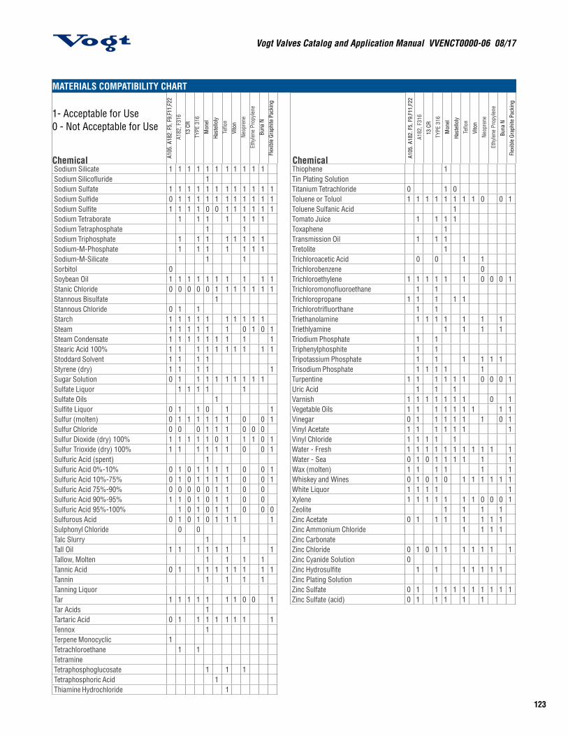
123
Vogt Valves Catalog and Application Manual VVENCT0000-06 08/17
MATERIALS COMPATIBILITY CHART
1- Acceptable for Use 0 - Not Acceptable for Use
Chemical A105
. A18
2. F
5, F
9,F1
1,F2
2
A182
, F31
6
13 C
R
TYPE
316
Mon
el
Hast
ello
ly
Teflo
n
Vito
n
Neop
rene
Ethy
lene
Pro
pyle
ne
Buna
N
Flex
ible
Gra
phite
Pac
king
Chemical A105
. A18
2. F
5, F
9,F1
1,F2
2
A182
, F31
6
13 C
R
TYPE
316
Mon
el
Hast
ello
ly
Teflo
n
Vito
n
Neop
rene
Ethy
lene
Pro
pyle
ne
Buna
N
Flex
ible
Gra
phite
Pac
king
Sodium Silicate 1 1 1 1 1 1 1 1 1 1 1 Thiophene 1Sodium Silicofluride 1 Tin Plating SolutionSodium Sulfate 1 1 1 1 1 1 1 1 1 1 1 1 Titanium Tetrachloride 0 1 0Sodium Sulfide 0 1 1 1 1 1 1 1 1 1 1 1 Toluene or Toluol 1 1 1 1 1 1 1 1 0 0 1Sodium Sulfite 1 1 1 1 0 0 1 1 1 1 1 1 Toluene Sulfanic Acid 1Sodium Tetraborate 1 1 1 1 1 1 1 Tomato Juice 1 1 1 1Sodium Tetraphosphate 1 1 Toxaphene 1Sodium Triphosphate 1 1 1 1 1 1 1 1 Transmission Oil 1 1 1Sodium-M-Phosphate 1 1 1 1 1 1 1 Tretolite 1Sodium-M-Silicate 1 1 Trichloroacetic Acid 0 0 1 1Sorbitol 0 Trichlorobenzene 0Soybean Oil 1 1 1 1 1 1 1 1 1 1 Trichloroethylene 1 1 1 1 1 1 0 0 0 1Stanic Chloride 0 0 0 0 0 1 1 1 1 1 1 1 Trichloromonofluoroethane 1 1Stannous Bisulfate 1 Trichloropropane 1 1 1 1 1Stannous Chloride 0 1 1 Trichlorotrifluorthane 1 1Starch 1 1 1 1 1 1 1 1 1 1 Triethanolamine 1 1 1 1 1 1 1Steam 1 1 1 1 1 1 0 1 0 1 Triethlyamine 1 1 1 1Steam Condensate 1 1 1 1 1 1 1 1 1 Triodium Phosphate 1 1Stearic Acid 100% 1 1 1 1 1 1 1 1 1 1 Triphenylphosphite 1 1Stoddard Solvent 1 1 1 1 Tripotassium Phosphate 1 1 1 1 1 1Styrene (dry) 1 1 1 1 1 Trisodium Phosphate 1 1 1 1 1Sugar Solution 0 1 1 1 1 1 1 1 1 1 Turpentine 1 1 1 1 1 1 0 0 0 1Sulfate Liquor 1 1 1 1 1 Uric Acid 1 1 1Sulfate Oils 1 Varnish 1 1 1 1 1 1 1 0 1Sulfite Liquor 0 1 1 0 1 1 Vegetable Oils 1 1 1 1 1 1 1 1 1Sulfur (molten) 0 1 1 1 1 1 1 0 0 1 Vinegar 0 1 1 1 1 1 1 0 1Sulfur Chloride 0 0 0 1 1 1 0 0 0 Vinyl Acetate 1 1 1 1 1 1 1Sulfur Dioxide (dry) 100% 1 1 1 1 1 0 1 1 1 0 1 Vinyl Chloride 1 1 1 1 1Sulfur Trioxide (dry) 100% 1 1 1 1 1 1 0 0 1 Water - Fresh 1 1 1 1 1 1 1 1 1 1 1Sulfuric Acid (spent) 1 Water - Sea 0 1 0 1 1 1 1 1 1Sulfuric Acid 0%-10% 0 1 0 1 1 1 1 0 0 1 Wax (molten) 1 1 1 1 1 1Sulfuric Acid 10%-75% 0 1 0 1 1 1 1 0 0 1 Whiskey and Wines 0 1 0 1 0 1 1 1 1 1 1Sulfuric Acid 75%-90% 0 0 0 0 0 1 1 0 0 White Liquor 1 1 1 1 1Sulfuric Acid 90%-95% 1 1 0 1 0 1 1 0 0 Xylene 1 1 1 1 1 1 1 0 0 0 1Sulfuric Acid 95%-100% 1 0 1 0 1 1 0 0 0 Zeolite 1 1 1 1Sulfurous Acid 0 1 0 1 0 1 1 1 1 Zinc Acetate 0 1 1 1 1 1 1 1Sulphonyl Chloride 0 0 Zinc Ammonium Chloride 1 1 1 1Talc Slurry 1 1 Zinc CarbonateTall Oil 1 1 1 1 1 1 1 Zinc Chloride 0 1 0 1 1 1 1 1 1 1Tallow, Molten 1 1 1 1 Zinc Cyanide Solution 0Tannic Acid 0 1 1 1 1 1 1 1 1 1 Zinc Hydrosulfite 1 1 1 1 1 1 1Tannin 1 1 1 1 Zinc Plating SolutionTanning Liquor Zinc Sulfate 0 1 1 1 1 1 1 1 1 1 1Tar 1 1 1 1 1 1 1 0 0 1 Zinc Sulfate (acid) 0 1 1 1 1 1Tar Acids 1Tartaric Acid 0 1 1 1 1 1 1 1 1Tennox 1Terpene Monocyclic 1Tetrachloroethane 1 1TetramineTetraphosphoglucosate 1 1 1Tetraphosphoric Acid 1Thiamine Hydrochloride 1
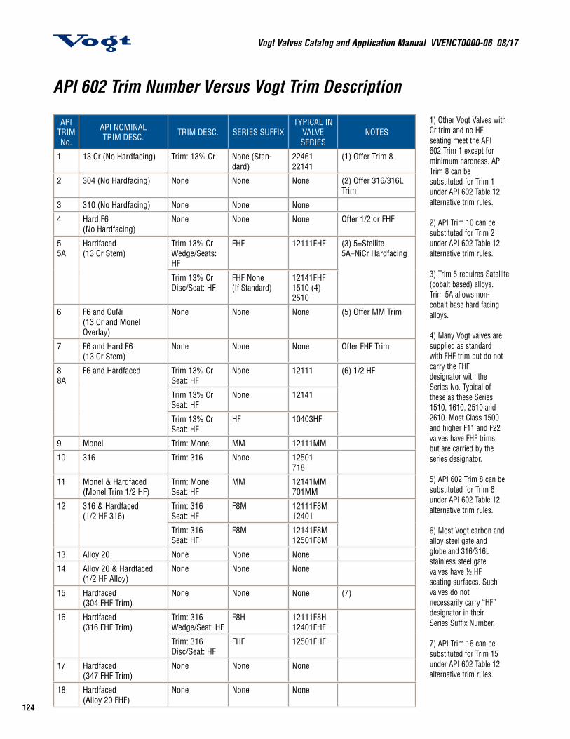
Vogt Valves Catalog and Application Manual VVENCT0000-06 08/17
124
API TRIM No.
API NOMINAL TRIM DESC. TRIM DESC. SERIES SUFFIX
TYPICAL IN VALVE SERIES
NOTES
1 13 Cr (No Hardfacing) Trim: 13% Cr None (Stan-dard)
22461 22141
(1) Offer Trim 8.
2 304 (No Hardfacing) None None None (2) Offer 316/316L Trim
3 310 (No Hardfacing) None None None
4 Hard F6 (No Hardfacing)
None None None Offer 1/2 or FHF
55A
Hardfaced(13 Cr Stem)
Trim 13% CrWedge/Seats: HF
FHF 12111FHF (3) 5=Stellite5A=NiCr Hardfacing
Trim 13% CrDisc/Seat: HF
FHF None (If Standard)
12141FHF1510 (4) 2510
6 F6 and CuNi(13 Cr and Monel Overlay)
None None None (5) Offer MM Trim
7 F6 and Hard F6 (13 Cr Stem)
None None None Offer FHF Trim
88A
F6 and Hardfaced Trim 13% CrSeat: HF
None 12111 (6) 1/2 HF
Trim 13% CrSeat: HF
None 12141
Trim 13% CrSeat: HF
HF 10403HF
9 Monel Trim: Monel MM 12111MM
10 316 Trim: 316 None 12501718
11 Monel & Hardfaced(Monel Trim 1/2 HF)
Trim: Monel Seat: HF
MM 12141MM701MM
12 316 & Hardfaced (1/2 HF 316)
Trim: 316Seat: HF
F8M 12111F8M12401
Trim: 316 Seat: HF
F8M 12141F8M12501F8M
13 Alloy 20 None None None
14 Alloy 20 & Hardfaced(1/2 HF Alloy)
None None None
15 Hardfaced(304 FHF Trim)
None None None (7)
16 Hardfaced(316 FHF Trim)
Trim: 316Wedge/Seat: HF
F8H 12111F8H12401FHF
Trim: 316Disc/Seat: HF
FHF 12501FHF
17 Hardfaced(347 FHF Trim)
None None None
18 Hardfaced(Alloy 20 FHF)
None None None
1) Other Vogt Valves with Cr trim and no HF seating meet the API 602 Trim 1 except for minimum hardness. API Trim 8 can be substituted for Trim 1 under API 602 Table 12 alternative trim rules.
2) API Trim 10 can be substituted for Trim 2 under API 602 Table 12 alternative trim rules.
3) Trim 5 requires Satellite (cobalt based) alloys. Trim 5A allows non- cobalt base hard facing alloys.
4) Many Vogt valves are supplied as standard with FHF trim but do not carry the FHF designator with the Series No. Typical of these as these Series 1510, 1610, 2510 and 2610. Most Class 1500 and higher F11 and F22 valves have FHF trims but are carried by the series designator.
5) API 602 Trim 8 can be substituted for Trim 6 under API 602 Table 12 alternative trim rules.
6) Most Vogt carbon and alloy steel gate and globe and 316/316L stainless steel gate valves have ½ HF seating surfaces. Such valves do not necessarily carry “HF” designator in their Series Suffix Number.
7) API Trim 16 can be substituted for Trim 15 under API 602 Table 12 alternative trim rules.
API 602 Trim Number Versus Vogt Trim Description

125
Vogt Valves Catalog and Application Manual VVENCT0000-06 08/17
MATERIAL FORGINGS CASTINGS WROUGHT FITTINGS
Carbon Steel Cold Temperature Service
A105 A350-LF2
A216-WCBA352-LCC
A234-WPB A420-WPL6
Carbon-1/2 Moly Alloy Steel Cold Temperature Service
A182-F1 A217-WC1 A352-LC1
A234-WP1
3-1/2 Nickel Alloy Steel Low Temperature Service A350-LF3 A352-LC3 A420-WPL3
1/2 Cr-1/2 Mo Alloy Steel 1/2 Cr-1/2 Mo-1 Ni Alloy Steel3/4 Cr-1 Mo-3/4 Ni Alloy Steel1 Cr-1/2 Mo Alloy Steel
A182-F2
A182-F12 CL2
A217-WC4A217-WC5
A234-WP12 CL2
1-1/4 Cr-1/2 Mo Alloy Steel 2-1/4 Cr-1 Mo Alloy Steel5 Cr-1/2 Mo Alloy Steel5 Cr-1/2 Mo Alloy Steel9 Cr-1 Mo Alloy Steel13 Cr Alloy Steel
A182-F11 CL2 A182-F22 CL3A182-F5A182-F5aA182-F9A182-F6
A217-WC6A217-WC9
A217-C5A217-C12A743-CA15
A234-WP11 CL2A234-WP22 CL3A234-WP5
A234-WP9
Type 304 Stainless Steel (18 Cr-8 Ni) Standard Low Carbon High Temperature Service
A182-F304A182-F304LA182-F304H
A351-CF8A351-CF3A351 CF10
A403-WP304A403-WP304LA403-WP304H
Type 310 Stainless Steel (25 Cr-20 Ni)Type 316 Stainless Steel (16 Cr-12 Ni-2 Mo) Standard Low Carbon High Temperature Service
A182-F310H
A182-F316A182-F316LA182-F316H
A351-CK20
A351-CF8MA351-CF3MA351-CF10M
A403-WP310
A403-WP316A403-WP316LA403-WP316H
Type 317 Stainless Steel (18 Cr-13 Ni-3 Mo)Type 321 Stainless Steel (18 Cr-10 Ni-Ti) Standard High Temperature Service
A182 - F317
A182-F321A182-F321H
A351 - CG8M A403-WP317
A403-WP321A403-WP321H
Type 347 Stainless Steel (18 Cr-10 Ni-Cb) Standard High Temperature Service
A182-F347A182-F347H
A351-CF8C A403-WP347A403-WP347H
Type 348 Stainless Steel (18 Cr-10 Ni-Cb) Standard High Temperature Service
A182-F348A182-F348H
A403-WP348A403-WP348H
Cross-Reference of ASTM Material Specifications Covering Cast and Forged Valves
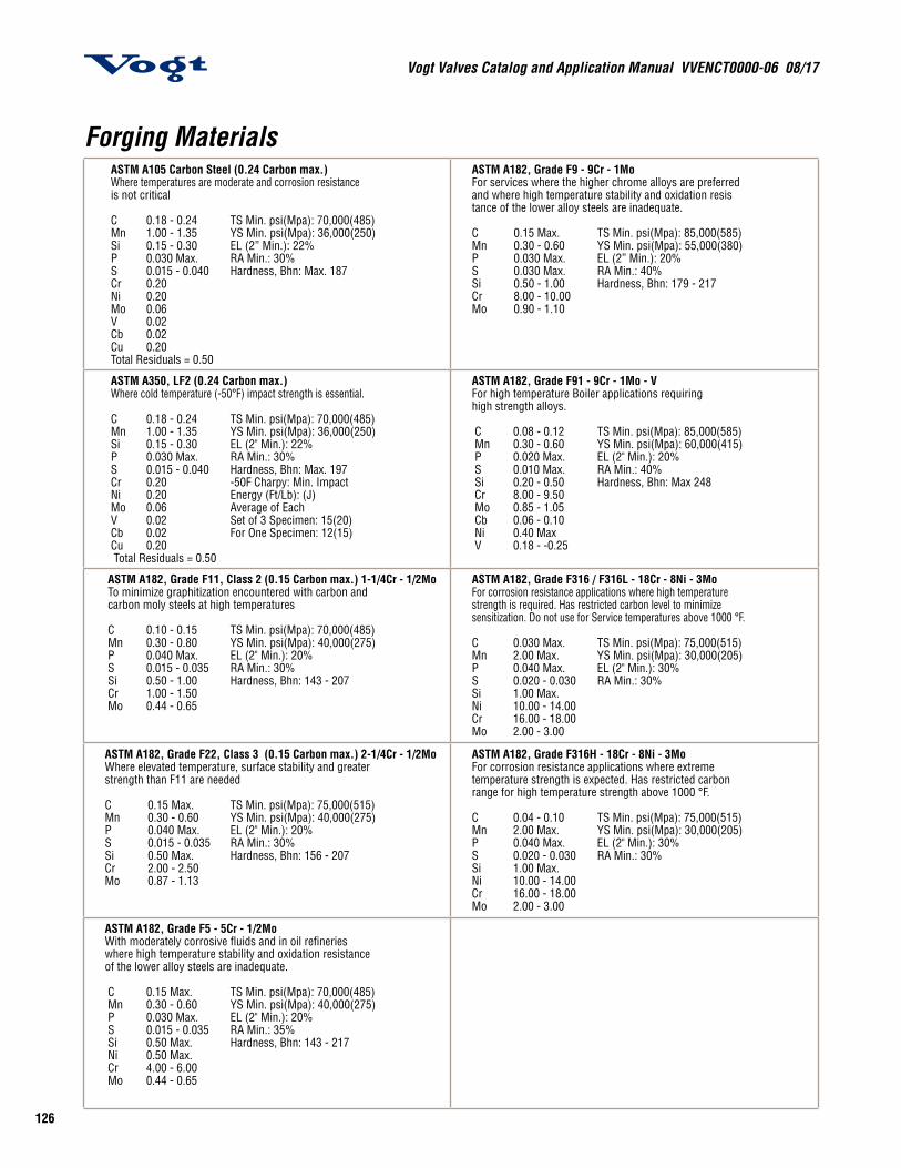
Vogt Valves Catalog and Application Manual VVENCT0000-06 08/17
126
Forging Materials ASTM A105 Carbon Steel (0.24 Carbon max.) Where temperatures are moderate and corrosion resistance is not critical
C 0.18 - 0.24 TS Min. psi(Mpa): 70,000(485) Mn 1.00 - 1.35 YS Min. psi(Mpa): 36,000(250) Si 0.15 - 0.30 EL (2” Min.): 22% P 0.030 Max. RA Min.: 30% S 0.015 - 0.040 Hardness, Bhn: Max. 187 Cr 0.20 Ni 0.20 Mo 0.06 V 0.02 Cb 0.02 Cu 0.20 Total Residuals = 0.50
ASTM A182, Grade F9 - 9Cr - 1MoFor services where the higher chrome alloys are preferred and where high temperature stability and oxidation resis tance of the lower alloy steels are inadequate.
C 0.15 Max. TS Min. psi(Mpa): 85,000(585) Mn 0.30 - 0.60 YS Min. psi(Mpa): 55,000(380)P 0.030 Max. EL (2” Min.): 20% S 0.030 Max. RA Min.: 40%Si 0.50 - 1.00 Hardness, Bhn: 179 - 217Cr 8.00 - 10.00Mo 0.90 - 1.10
ASTM A350, LF2 (0.24 Carbon max.) Where cold temperature (-50°F) impact strength is essential.
C 0.18 - 0.24 TS Min. psi(Mpa): 70,000(485) Mn 1.00 - 1.35 YS Min. psi(Mpa): 36,000(250) Si 0.15 - 0.30 EL (2" Min.): 22% P 0.030 Max. RA Min.: 30% S 0.015 - 0.040 Hardness, Bhn: Max. 197 Cr 0.20 -50F Charpy: Min. Impact Ni 0.20 Energy (Ft/Lb): (J) Mo 0.06 Average of Each V 0.02 Set of 3 Specimen: 15(20) Cb 0.02 For One Specimen: 12(15) Cu 0.20 Total Residuals = 0.50
ASTM A182, Grade F91 - 9Cr - 1Mo - V For high temperature Boiler applications requiringhigh strength alloys.
C 0.08 - 0.12 TS Min. psi(Mpa): 85,000(585) Mn 0.30 - 0.60 YS Min. psi(Mpa): 60,000(415) P 0.020 Max. EL (2" Min.): 20% S 0.010 Max. RA Min.: 40% Si 0.20 - 0.50 Hardness, Bhn: Max 248 Cr 8.00 - 9.50 Mo 0.85 - 1.05 Cb 0.06 - 0.10 Ni 0.40 Max V 0.18 - -0.25
ASTM A182, Grade F11, Class 2 (0.15 Carbon max.) 1-1/4Cr - 1/2Mo To minimize graphitization encountered with carbon and carbon moly steels at high temperatures
C 0.10 - 0.15 TS Min. psi(Mpa): 70,000(485) Mn 0.30 - 0.80 YS Min. psi(Mpa): 40,000(275) P 0.040 Max. EL (2" Min.): 20% S 0.015 - 0.035 RA Min.: 30% Si 0.50 - 1.00 Hardness, Bhn: 143 - 207 Cr 1.00 - 1.50 Mo 0.44 - 0.65
ASTM A182, Grade F316 / F316L - 18Cr - 8Ni - 3MoFor corrosion resistance applications where high temperature strength is required. Has restricted carbon level to minimize sensitization. Do not use for Service temperatures above 1000 °F.
C 0.030 Max. TS Min. psi(Mpa): 75,000(515) Mn 2.00 Max. YS Min. psi(Mpa): 30,000(205)P 0.040 Max. EL (2" Min.): 30% S 0.020 - 0.030 RA Min.: 30%Si 1.00 Max.Ni 10.00 - 14.00Cr 16.00 - 18.00Mo 2.00 - 3.00
ASTM A182, Grade F22, Class 3 (0.15 Carbon max.) 2-1/4Cr - 1/2MoWhere elevated temperature, surface stability and greaterstrength than F11 are needed
C 0.15 Max. TS Min. psi(Mpa): 75,000(515) Mn 0.30 - 0.60 YS Min. psi(Mpa): 40,000(275)P 0.040 Max. EL (2" Min.): 20%S 0.015 - 0.035 RA Min.: 30%Si 0.50 Max. Hardness, Bhn: 156 - 207Cr 2.00 - 2.50Mo 0.87 - 1.13
ASTM A182, Grade F316H - 18Cr - 8Ni - 3MoFor corrosion resistance applications where extreme temperature strength is expected. Has restricted carbon range for high temperature strength above 1000 °F.
C 0.04 - 0.10 TS Min. psi(Mpa): 75,000(515) Mn 2.00 Max. YS Min. psi(Mpa): 30,000(205) P 0.040 Max. EL (2" Min.): 30%S 0.020 - 0.030 RA Min.: 30%Si 1.00 Max.Ni 10.00 - 14.00Cr 16.00 - 18.00Mo 2.00 - 3.00
ASTM A182, Grade F5 - 5Cr - 1/2MoWith moderately corrosive fluids and in oil refinerieswhere high temperature stability and oxidation resistance of the lower alloy steels are inadequate.
C 0.15 Max. TS Min. psi(Mpa): 70,000(485) Mn 0.30 - 0.60 YS Min. psi(Mpa): 40,000(275) P 0.030 Max. EL (2" Min.): 20% S 0.015 - 0.035 RA Min.: 35% Si 0.50 Max. Hardness, Bhn: 143 - 217 Ni 0.50 Max. Cr 4.00 - 6.00 Mo 0.44 - 0.65
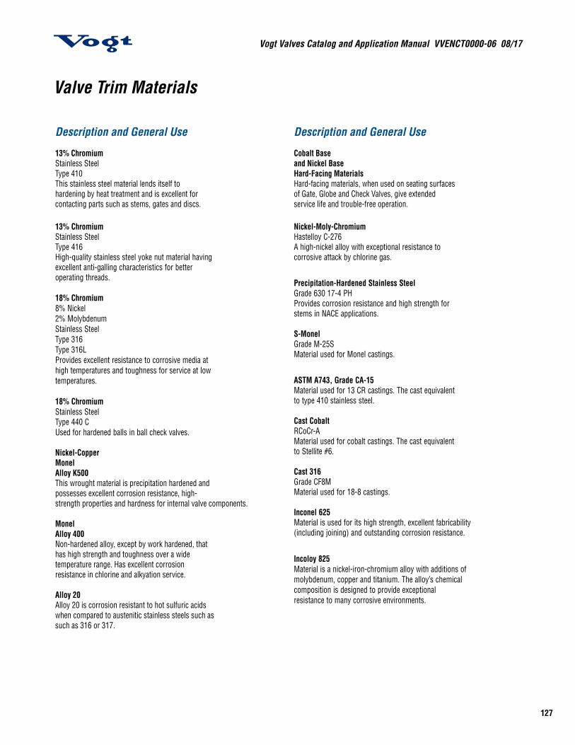
127
Vogt Valves Catalog and Application Manual VVENCT0000-06 08/17
Valve Trim Materials
Description and General Use 13% Chromium Stainless Steel Type 410 This stainless steel material lends itself to hardening by heat treatment and is excellent for contacting parts such as stems, gates and discs.
13% Chromium Stainless Steel Type 416 High-quality stainless steel yoke nut material having excellent anti-galling characteristics for better operating threads.
18% Chromium 8% Nickel 2% Molybdenum Stainless Steel Type 316 Type 316L Provides excellent resistance to corrosive media at high temperatures and toughness for service at low temperatures.
18% Chromium Stainless Steel Type 440 CUsed for hardened balls in ball check valves.
Nickel-Copper Monel Alloy K500 This wrought material is precipitation hardened and possesses excellent corrosion resistance, high- strength properties and hardness for internal valve components. Monel Alloy 400 Non-hardened alloy, except by work hardened, that has high strength and toughness over a wide temperature range. Has excellent corrosion resistance in chlorine and alkyation service. Alloy 20 Alloy 20 is corrosion resistant to hot sulfuric acids when compared to austenitic stainless steels such as such as 316 or 317.
Description and General Use Cobalt Base and Nickel Base Hard-Facing Materials Hard-facing materials, when used on seating surfaces of Gate, Globe and Check Valves, give extended service life and trouble-free operation.
Nickel-Moly-Chromium Hastelloy C-276 A high-nickel alloy with exceptional resistance to corrosive attack by chlorine gas.
Precipitation-Hardened Stainless Steel Grade 630 17-4 PH Provides corrosion resistance and high strength for stems in NACE applications. S-Monel Grade M-25S Material used for Monel castings.
ASTM A743, Grade CA-15 Material used for 13 CR castings. The cast equivalent to type 410 stainless steel. Cast Cobalt RCoCr-A Material used for cobalt castings. The cast equivalent to Stellite #6. Cast 316 Grade CF8M Material used for 18-8 castings. Inconel 625 Material is used for its high strength, excellent fabricability (including joining) and outstanding corrosion resistance.
Incoloy 825 Material is a nickel-iron-chromium alloy with additions of molybdenum, copper and titanium. The alloy’s chemical composition is designed to provide exceptional resistance to many corrosive environments.

Vogt Valves Catalog and Application Manual VVENCT0000-06 08/17
128
Meeting the Demands of TodaySTANDARD PACKINGVogt standard valves are packed with one of the following asbestos-free packing sets:
FLEXIBLE GRAPHITE PACKINGA 95% by weight minimum carbon packing set that consists of a cylindrical ring of flexible graphite packing supported on the top and bottom and braided graphite filament packing rings. The packing dispersed and embedded active corrosion inhibitor to protect against stem pitting. It may be used in fluids having a pH range of 0-14. The packing has minimal residues as follows:
Leachable Chlorides: 100PPM maximumTotal Chlorides: 500PPM MaximumTotal Sulfur: 1000PPM MaximumPTFE: None
MOLDED TFE TEFLON-SHAPED PACKINGVogt valves that have a series number suffixed with the letter “T” are packed with a molded, shaped TFE packing. This virgin TFE material needs no corrosion inhibitor in its composition, and its self-energizing shape ensures superior service and low gland bolting loads in high pressure liquid and dry gas applications. It may also be used in fluids having a pH range of 0-14. Temperature range: -120˚F to 500˚F (-84˚ to 260˚C).
Since this packing has directional sealing, it can be reoriented for valves used in vacuum and/or combination vacuum/pressure service.
OTHER PACKINGOther packing sets can be placed in Vogt valves at the user’s option.
Asbestos-Free ValvesAsbestos-Free PackingAsbestos-Free Gasket
SAFE – EFFICIENT in retaining high and low temperature media.
ADVANCED TECHNOLOGY PROVIDES: Environmental acceptance Elimination of media contamination Leek-proof integrity High thermal conductivity Self-lubricating operation Shrinkage resistance Corrosion-resistant inhibitor Less frequent maintenance Longer service life
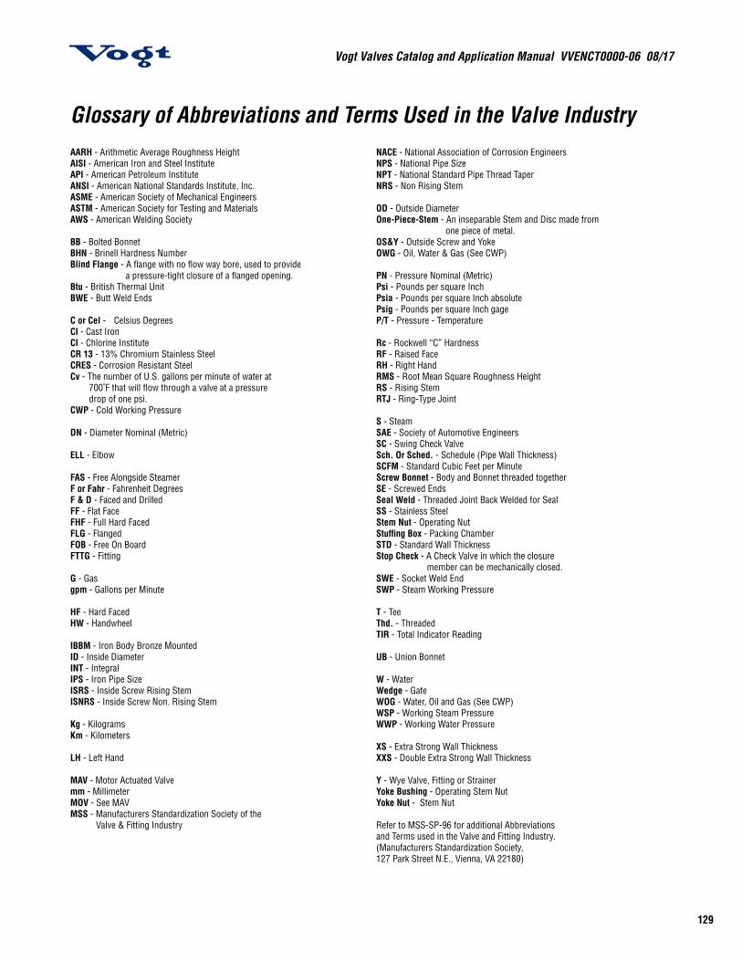
129
Vogt Valves Catalog and Application Manual VVENCT0000-06 08/17
Glossary of Abbreviations and Terms Used in the Valve IndustryAARH - Arithmetic Average Roughness Height NACE - National Association of Corrosion Engineers AISI - American Iron and Steel Institute NPS - National Pipe Size API - American Petroleum Institute NPT - National Standard Pipe Thread Taper ANSI - American National Standards Institute, Inc. NRS - Non Rising Stem ASME - American Society of Mechanical Engineers ASTM - American Society for Testing and Materials OD - Outside Diameter AWS - American Welding Society One-Piece-Stem - An inseparable Stem and Disc made from one piece of metal. BB - Bolted Bonnet OS&Y - Outside Screw and Yoke BHN - Brinell Hardness Number OWG - Oil, Water & Gas (See CWP) Blind Flange - A flange with no flow way bore, used to provide a pressure-tight closure of a flanged opening. PN - Pressure Nominal (Metric) Btu - British Thermal Unit Psi - Pounds per square Inch BWE - Butt Weld Ends Psia - Pounds per square Inch absolute Psig - Pounds per square Inch gage C or Cel - Celsius Degrees P/T - Pressure - Temperature CI - Cast Iron CI - Chlorine Institute Rc - Rockwell “C” Hardness CR 13 - 13% Chromium Stainless Steel RF - Raised Face CRES - Corrosion Resistant Steel RH - Right Hand Cv - The number of U.S. gallons per minute of water at RMS - Root Mean Square Roughness Height 700˚F that will flow through a valve at a pressure RS - Rising Stem drop of one psi. RTJ - Ring-Type Joint CWP - Cold Working Pressure S - Steam DN - Diameter Nominal (Metric) SAE - Society of Automotive Engineers SC - Swing Check Valve ELL - Elbow Sch. Or Sched. - Schedule (Pipe Wall Thickness) SCFM - Standard Cubic Feet per Minute FAS - Free Alongside Steamer Screw Bonnet - Body and Bonnet threaded together F or Fahr - Fahrenheit Degrees SE - Screwed Ends F & D - Faced and Drilled Seal Weld - Threaded Joint Back Welded for SealFF - Flat Face SS - Stainless Steel FHF - Full Hard Faced Stem Nut - Operating Nut FLG - Flanged Stuffing Box - Packing Chamber FOB - Free On Board STD - Standard Wall Thickness FTTG - Fitting Stop Check - A Check Valve in which the closure member can be mechanically closed. G - Gas SWE - Socket Weld End gpm - Gallons per Minute SWP - Steam Working Pressure HF - Hard Faced T - Tee HW - Handwheel Thd. - Threaded TIR - Total Indicator Reading IBBM - Iron Body Bronze Mounted ID - Inside Diameter UB - Union Bonnet INT - Integral IPS - Iron Pipe Size W - Water ISRS - Inside Screw Rising Stem Wedge - Gate ISNRS - Inside Screw Non. Rising Stem WOG - Water, Oil and Gas (See CWP) WSP - Working Steam Pressure Kg - Kilograms WWP - Working Water Pressure Km - Kilometers XS - Extra Strong Wall Thickness LH - Left Hand XXS - Double Extra Strong Wall Thickness MAV - Motor Actuated Valve Y - Wye Valve, Fitting or Strainer mm - Millimeter Yoke Bushing - Operating Stem Nut MOV - See MAV Yoke Nut - Stem Nut MSS - Manufacturers Standardization Society of the Valve & Fitting Industry Refer to MSS-SP-96 for additional Abbreviations and Terms used in the Valve and Fitting Industry. (Manufacturers Standardization Society, 127 Park Street N.E., Vienna, VA 22180)
Vogt Valves Catalog and Application Manual VVENCT0000-06 08/17
130
Standards in the Valve IndustryCodes and standards play an important role in the design and production of forged steel valves, fittings and unions. These Codes and standards cover material, product dimensions, design, examination, inspection, testing procedure, pressure/temperature ratings and safety.
Material standards are developed by such organizations as the American Society for Testing and Materials (ASTM), the American Iron and Steel Institute (AISI), the Society of Automotive Engineers (SAE) and the National Association of Corrosion Engineers (NACE).
The American National Standards Institute, Inc. (ANSI) has a membership comprised of both user and producer groups and serves as the national coordinator for the majority of code and product standards related to the Valve and Fittings Industry. Product standards are also developed and issued by individual user and/or manufacturing agencies such as the American Society of Mechanical Engineers (ASME), American Petroleum Institute (API) and the Manufacturers’ Standardization Society (MSS).
Procedural and Safety standards are issued by ANSI, MSS and ASME.
Following is a partial list of the codes and standards that have a direct bearing on the design and production of Vogt’s forged steel valves, fittings and unions. The codes and standards are interrelated as the following descriptions project:
ASME Boiler & Pressure Vessel CodeSection I – Power BoilersSection II – Material SpecificationsSection III – Nuclear Power Plant ComponentsSection V – Non-destructive ExaminationSection VIII – Pressure VesselsSection IX – Welding and Brazing Qualifications
The previous codes (Sections I, III and VIII) cover construction requirements for Boilers, Pressure Vessels and Nuclear Components that require Authorized Inspection Agency involvement. Section I and VIII codes relate to the Boiler and Pressure Vessel proper and not to external piping. Section III code includes rules for nuclear components including piping. Section II, V and IX codes cover material, non-destructive examination and welding requirements, respectively, for ASME construction.
ASME Codes for Pressure PipingB31.1 – Power PipingB31.2 – Fuel Gas PipingB31.3 – Process PipingB31.4 - Pipeline Transportation Systems for Liquid Hydrocarbon and Other LiquidsB31.5 - Refrigeration Piping and Heat Transfer ComponentsB31.8 - Gas Transmission and Distribution Piping SystemsB31.9 - Building Services Piping SystemsB31.11 - Slurry Transportation Piping Systems
The above are piping construction codes that include requirements for design, materials, fabrication, examination, testing, inspection and components. Valve, fitting, and flange requirements used in these piping systems are normally referenced standards, as follows:
Inspection and TestingMSS-SP-61 - Pressure Testing of Steel Valves
API-598 - Valve Inspection and Testing
The above highly recognized standards provide detailed instructions for the inspection and testing of valves.
Valve StandardsASME B16.34 - Valves Flanged, Threaded and Welding End
API-600 / ISO 10434 – Bolted Bonnet Steel Gate Valves for Petroleum and Natural Gas Industries
API-602 / ISO 15761 – Steel Gate, Globe and Check Valves for Sizes DN 100 and Smaller for the Petroleum and Natural Gas Industries
MSS-SP-99 - Instrument Valves
MSS-SP-105 - Instrument Valves for Code Applications
MSS-SP-134 - Valves for Cryogenic Service Including Requirements for Body/Bonnet Extensions
The above are component (valve) standards used for construction of Vogt valves as noted in this catalog
131
Vogt Valves Catalog and Application Manual VVENCT0000-06 08/17
Standards in the Valve IndustryValve and Flange DetailsASME B16.5 - Pipe Flanges and Flanged Fittings
ASME B16.11 - Forged Fittings, Socket-Welding and Threaded
ASME B1.20.1 - Pipe Threads, General Purpose, Inch
ASME B16.10 - Face to Face and End to End Dimensions of Valves
ASME B16.20 - Metallic Gaskets for Pipe Flanges: Ring Joint, Spiral Wound, and Jacketed
ASME B16.25 - Buttwelding Ends
MSS-SP-6 - Standard Finishes for Contact Faces of Pipe Flanges and Connecting-End Flanges of Valves and Fittings
MSS-SP-25 - Standard Marking Systems for Valves, Fittings, Flanges and Unions
MSS-SP-45 - Bypass and Drain Connections
The above standards are detailed dimensional, marking, finish and bypass valve and fitting instructions for use in the manufacture of valves, flanges and fittings. The product standards normally refer to these standards for detailed instructions.
NACE StandardMR0175 / ISO 15156-1 Petroleum and Natural Gas Industries- Materials for use in H2S- containing Environments in Oil and Gas Production.
This standard is a recognized practice for selection of materials for construction of valves to be used in a sour environment. Such materials are recommended when Stress Corrosion Cracking (SCC) and/or Sulfide Stress Cracking (SSC) is anticipated.
MR0103 Materials Resistant to Sulfide Stress Cracking in Corrosive Petroleum Refining Environments.
This standard is a recognized practice for selection of materials for construction of valves to be used in a sour environment. Such materials are recommended when Sulfide Stress Cracking (SSC) is anticipated.
Chlorine InstitutePamphlet # 6 – Piping Systems for Dry Chlorine
This publication is intended to provide useful information concerning the construction of Chlorine piping systems including valves.
For detailed Material Standards used by Vogt valves, see pages 126 and 127
Addresses:
American Iron & Steel Institute (AISI)1140 Connecticut Ave., NWSuite 705Washington, DC 20036
American National Standards Institute (ANSI)1819 L Street, NW6th floorWashington, DC 20036
American Petroleum Institute (API)1220 L Street, NWWashington, DC 20005-4070
American Society of Mechanical Engineers (ASME)ASME InternationalThree Park AvenueNew York, NY 10016-5990
American Society of Testing and Materials100 Barr Harbor DriveWest Conshohocken, PA 19428-2959
Manufacturers Standardization Society of the Valve & Fitting Industry127 Park Street, N.E.Vienna, VA 22180-4602
NACE International1440 South Creek Drive Houston, TX 77084-4906
Society of Automotive Engineers (SAE)400 Commonwealth DriveWarrendale, PA 15096-0001
The Chlorine Institute, Inc.1300 Wilson Blvd.Arlington, VA 22209
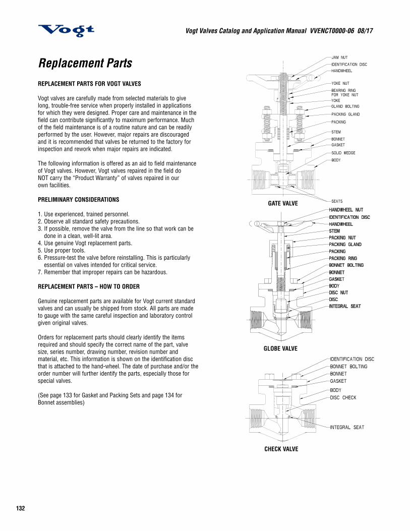
Vogt Valves Catalog and Application Manual VVENCT0000-06 08/17
132
Replacement PartsREPLACEMENT PARTS FOR VOGT VALVES
Vogt valves are carefully made from selected materials to give long, trouble-free service when properly installed in applications for which they were designed. Proper care and maintenance in the field can contribute significantly to maximum performance. Much of the field maintenance is of a routine nature and can be readily performed by the user. However, major repairs are discouraged and it is recommended that valves be returned to the factory for inspection and rework when major repairs are indicated.
The following information is offered as an aid to field maintenance of Vogt valves. However, Vogt valves repaired in the field do NOT carry the “Product Warranty” of valves repaired in our own facilities.
PRELIMINARY CONSIDERATIONS
1. Use experienced, trained personnel.2. Observe all standard safety precautions.3. If possible, remove the valve from the line so that work can be
done in a clean, well-lit area.4. Use genuine Vogt replacement parts.5. Use proper tools.6. Pressure-test the valve before reinstalling. This is particularly
essential on valves intended for critical service.7. Remember that improper repairs can be hazardous.
REPLACEMENT PARTS – HOW TO ORDER
Genuine replacement parts are available for Vogt current standard valves and can usually be shipped from stock. All parts are made to gauge with the same careful inspection and laboratory control given original valves.
Orders for replacement parts should clearly identify the items required and should specify the correct name of the part, valve size, series number, drawing number, revision number and material, etc. This information is shown on the identification disc that is attached to the hand-wheel. The date of purchase and/or the order number will further identify the parts, especially those for special valves.
(See page 133 for Gasket and Packing Sets and page 134 for Bonnet assemblies)
GLOBE VALVE
CHECK VALVE
GATE VALVE

133
Vogt Valves Catalog and Application Manual VVENCT0000-06 08/17
Packing and GasketsA high degree of standardization of Vogt Valves Vogt valves permits a small stock of replacement packing and gaskets to service your Vogt valves. The following matrix and part number tables provide the details for the purchasing of replacement gaskets for your Vogt bolted bonnet valves and packing for our popular class 150, 300, 600, 800, 1500, 1690 and 2680 gate, globe and angle valves.*
* API 602/ASME B16.34 type valves—see valve description. For other valves, consult your Vogt Valves distributor.
** Order packing by Packing Set PN. Individual rings of complete set will be supplied.*** One-piece or two-piece Packing Cartridge will be supplied
when this PN is used.
Packing Matrix
PRESSURE NPSCLASS DN
½15
¾20
1 25
1¼32
1½40
250
2½65
380
4100
150 Conventional Port B B C D D E F F G
300 Conventional Port B B C D D E F F G
600 Conventional Port B B C D D E F F G
800 Conventional Port B* B C D D E F F -
1500 Conventional Port J J D E E F - - -
600 and 800 Full Port B C D - E F - - -
1500 Full Port B D E E F - - - -
Class 800 LTD Class C C D - F F - - -
Class 1690 LTD Class C C E - G G - - -
Class 2680 LTD (Globe) C E E - G G - - -
Class 2680 LTD Class (Gate) C E E - H H - - -Gasket Matrix (Spiral-wound Type)
PRESSURE NPSCLASS DN
½15
¾20
1 25
1¼32
1½40
250
2½65
380
4100
150 Conventional Port A A B C C D E E F
300 Conventional Port A A B C C D E E F
600 Conventional Port A A B C C D E E F
800 Conventional Port A* A B C C D E F -
1500 Conventional Port A A B C C D - - -
600 and 800 Full Port A B G - D E - - -
1500 Full Port A B C C D - - - -
Packing Set Part Numbers
MATRIXFLEXIBLE GRAPHITE FLUOROPOLYMER
PACKING SET PN** PACKING CARTRIDGE PN*** PACKING SET PN**
B 55163 55175 55276
C 55166 55176 55286
D 55167 55177 55287
E 55169 55178 55288
F 55170 - 55289
G 55171 - 55285
J 55165 55179 55294
H 55173 - -
Gasket Usage Table
GASKET WHERE USED
304/Graphite A105, A182-F5, F9, F11 Cl 2, F22 C l3 Valves
316/Graphite A182, F316 Valves
316/fluoropolymer “T” Suffix Trimmed Valves
Monel/Graphite MM & HF Acid Trimmed Valves
Monel/fluoropolymer Chlorine Valves
Gasket Part Numbers
GASKET MATRIX PART NUMBER SPIRAL-WOUND GASKET DESCRIPTION
A 5500255003550045500555006
304/Graphite-filled316/Graphite-filled316/fluoropolymer-filledMonel/Graphite-filledMonel/fluoropolymer-filled
B 5500755008550095501055011
304/Graphite-filled316/Graphite-filled316/fluoropolymer-filledMonel/Graphite-filledMonel/fluoropolymer-filled
C 5502555026550275502855029
304/Graphite-filled316/Graphite-filled316/fluoropolymer-filledMonel/Graphite-filledMonel/fluoropolymer-filled
D 5501755018550195502055021
304/Graphite-filled316/Graphite-filled316/fluoropolymer-filledMonel/Graphite-filledMonel/fluoropolymer-filled
E 5503055031550325503355034
304/Graphite-filled316/Graphite-filled316/fluoropolymer-filledMonel/Graphite-filledMonel/fluoropolymer
F 55042550435504455045-
304/Graphite-filled316/Graphite-filled316/fluoropolymer-filledMonel/Graphite-filledMonel/fluoropolymer
G 5501255013550145501555016
304/Graphite-filled316/Graphite-filled316/fluoropolymer-filledMonel/Graphite-filledMonel/fluoropolymer
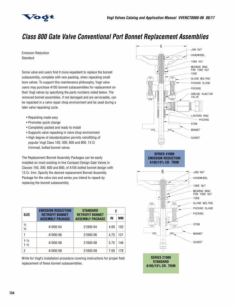
Vogt Valves Catalog and Application Manual VVENCT0000-06 08/17
134
SERIES 41000EMISSION REDUCTIONA105/13% CR. TRIM
SERIES 21000STANDARD
A105/13% CR. TRIM
Write for Vogt’s installation procedure covering instructions for proper field replacement of these bonnet subassemblies.
Class 800 Gate Valve Conventional Port Bonnet Replacement Assemblies
Emission Reduction Standard
Some valve end users find it more expedient to replace the bonnet subassembly, complete with new packing, when repacking small bore valves. To support this maintenance philosophy, Vogt valve users may purchase A105 bonnet subassemblies for replacement on their Vogt valves by specifying the parts numbers noted below. The removed bonnet assemblies, if not damaged and are serviceable, can be repacked in a valve repair shop environment and be used during a later valve repacking cycle.
• Repacking made easy • Promotes quick change • Completely packed and ready to install • Supports valve repacking in valve shop environment • High degree of standardization permits retrofitting of
popular Vogt Class 150, 300, 600 and 800, 13 Cr trimmed, bolted bonnet valves
The Replacement Bonnet Assembly Packages can be easily installed on most existing in-line Compact Design Gate Valves in Classes 150, 300, 600 and 800, of A105 bolted bonnet design with 13 Cr. trim. Specify the desired replacement Bonnet Assembly Package for the valve size and series you intend to repack by replacing the bonnet subassembly.
SIZEEMISSION REDUCTION
RETROFIT BONNET ASSEMBLY PACKAGE
STANDARD RETROFIT BONNET
ASSEMBLY PACKAGE
E
IN MM
½¾ 41000-04 21000-04 4.00 102
1 41000-06 21000-06 4.75 121
1-¼1-½ 41000-08 21000-08 5.75 146
2 41000-09 21000-09 7.00 178
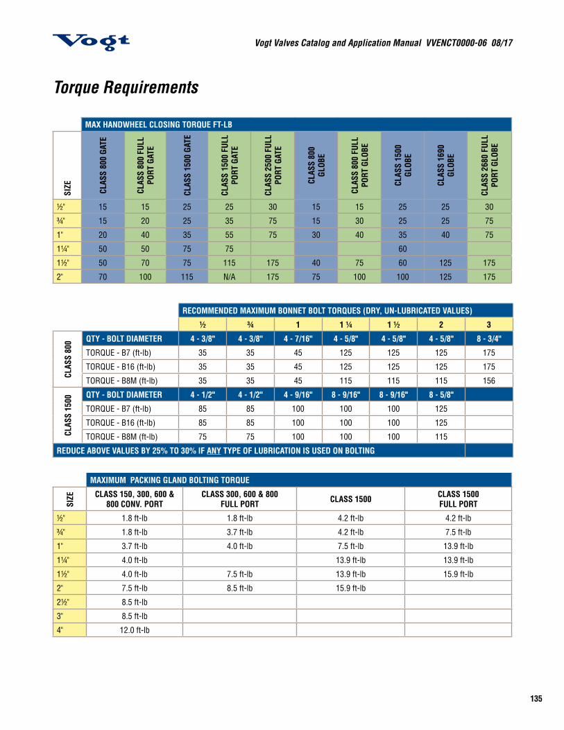
135
Vogt Valves Catalog and Application Manual VVENCT0000-06 08/17
Torque Requirements
MAX HANDWHEEL CLOSING TORQUE FT-LB
SIZE CLAS
S 80
0 GA
TE
CLAS
S 80
0 FU
LL
PORT
GAT
E
CLAS
S 15
00 G
ATE
CLAS
S 15
00 F
ULL
PORT
GAT
E
CLAS
S 25
00 F
ULL
PORT
GAT
E
CLAS
S 80
0 GL
OBE
CLAS
S 80
0 FU
LL
PORT
GLO
BE
CLAS
S 15
00
GLOB
E
CLAS
S 16
90
GLOB
E
CLAS
S 26
80 F
ULL
PORT
GLO
BE
½" 15 15 25 25 30 15 15 25 25 30
¾" 15 20 25 35 75 15 30 25 25 75
1" 20 40 35 55 75 30 40 35 40 75
1¼" 50 50 75 75 60
1½" 50 70 75 115 175 40 75 60 125 175
2" 70 100 115 N/A 175 75 100 100 125 175
RECOMMENDED MAXIMUM BONNET BOLT TORQUES (DRY, UN-LUBRICATED VALUES)
½ ¾ 1 1 ¼ 1 ½ 2 3
CLAS
S 80
0 QTY - BOLT DIAMETER 4 - 3/8" 4 - 3/8" 4 - 7/16" 4 - 5/8" 4 - 5/8" 4 - 5/8" 8 - 3/4"
TORQUE - B7 (ft-lb) 35 35 45 125 125 125 175
TORQUE - B16 (ft-lb) 35 35 45 125 125 125 175
TORQUE - B8M (ft-lb) 35 35 45 115 115 115 156
CLAS
S 15
00 QTY - BOLT DIAMETER 4 - 1/2" 4 - 1/2" 4 - 9/16" 8 - 9/16" 8 - 9/16" 8 - 5/8"
TORQUE - B7 (ft-lb) 85 85 100 100 100 125
TORQUE - B16 (ft-lb) 85 85 100 100 100 125
TORQUE - B8M (ft-lb) 75 75 100 100 100 115
REDUCE ABOVE VALUES BY 25% TO 30% IF ANY TYPE OF LUBRICATION IS USED ON BOLTING
MAXIMUM PACKING GLAND BOLTING TORQUE
SIZE CLASS 150, 300, 600 &
800 CONV. PORTCLASS 300, 600 & 800
FULL PORT CLASS 1500 CLASS 1500FULL PORT
½" 1.8 ft-lb 1.8 ft-lb 4.2 ft-lb 4.2 ft-lb
¾" 1.8 ft-lb 3.7 ft-lb 4.2 ft-lb 7.5 ft-lb
1" 3.7 ft-lb 4.0 ft-lb 7.5 ft-lb 13.9 ft-lb
1¼" 4.0 ft-lb 13.9 ft-lb 13.9 ft-lb
1½" 4.0 ft-lb 7.5 ft-lb 13.9 ft-lb 15.9 ft-lb
2" 7.5 ft-lb 8.5 ft-lb 15.9 ft-lb
2½" 8.5 ft-lb
3" 8.5 ft-lb
4" 12.0 ft-lb
Vogt Valves Catalog and Application Manual VVENCT0000-06 08/17
136
Valve Care Before InstallationVogt valves are carefully made from selected materials to give long, trouble-free service when properly installed in applications for which they were designed. Proper care and maintenance in the field can contribute significantly to maximum performance.
The care the valve receives between the time it is shipped by the manufacturer and installed in the piping system is important. During this period, the valve can be handled many times and can be kept in storage for long periods. Industrial valves are not delicate, but they are mechanical devices that should be treated as such and handled with care.
Vogt always provides valves with appropriate end covers to protect the end connections and to prevent foreign material from entering the valve. In addition, small valves are shipped in sealed cartons while larger valves are usually palletized. If at all practical, keep the valves in the cartons or on pallets with the end covers in place until ready to be installed. Storing the valves off the ground and indoors is always preferable. When stored outside, valves should be off the ground and protected by a weatherproof cover.
Prior to installation, the valves and nameplates should be checked for proper identification to be sure the valve is the proper type and of suitable pressure class. Actuate the valve to check for possible damage from shipping and handling. Also, it is extremely important to inspect the interior of both the valve and the adjoining pipe for cleanliness. By far, the major cause of seat leakage and seat damage is foreign material in the line. Also, inspect the end connections to be sure that pipe threads and flange faces are free of scratches, nicks or dents.
Routine Inspection and MaintenanceOnce the right valve is properly installed, field maintenance is of a generally routine nature and can be readily performed by the user. The critical areas of the valve include the stem threads and those locations where leakage will most likely occur – the stem packing, the bonnet joint, the seat and the end connections. It is desirable that a maintenance program be established that will include periodic inspection of the noted critical areas. Stem threads should be lubricated prior to installation and periodically as part of the regular inspection. A high pressure and temperature lubricant such as Dow Corning Molykote™ G-n paste should be used.
The most common location of a noticeable leak is at the stem seal. Leakage at the stem can usually be stopped by adjusting the packing. If leakage cannot be stopped by packing adjustment, repacking is indicated. However, back-seating the valve and attempting to repack under pressure is hazardous and is not recommended. Rather than attempting to repack under pressure, it is preferable to use the backseat to control stem leakage until a shutdown provides safe repacking conditions.
Major Field RepairMaintenance involving rework or replacement parts is considered major repair. When circumstances dictate field repair of Vogt valves, the following information is offered as an aid. It must be pointed out, however, that the Vogt valves repaired in the field are no longer under “Product Warranty,” and in no event is Vogt liable for any cause whatsoever. There are no warranties of any kind whatsoever, expressed or implied, other than those stated in Vogt’s current Terms and Conditions.
Preliminary Considerations for Valve Repair:
1. Use experienced, trained personnel. 2. Observe all standard safety precautions. 3. If possible, remove the valve from the line so that work can be done in a clean, well-lit area. 4. Use genuine Vogt replacement parts. 5. Use proper tools. 6. Pressure test the valve before reinstalling. This is particularly essential on valves intended for critical service. 7. Remember that improper repairs can be hazardous.
Care and Maintenance of Vogt Forged Steel Valves
137
Vogt Valves Catalog and Application Manual VVENCT0000-06 08/17
Replacement Parts … How to Order
Genuine replacement parts are available for Vogt current standard valves and can usually be shipped from stock. All parts are made to gauge with the same careful inspection and laboratory control given original valves.
Orders for replacement parts should clearly identify the items required and should specify the correct name of the part, valve size, series number, drawing number, revision number and material, etc. This information is shown on the identification disc that is attached to the hand-wheel. The date of purchase and/or the order number will further identify the parts, especially those for special valves.
The embossed number on each hand-wheel, having a prefix letter “V”, is the pattern number of the hand-wheel and has no relation to the ordering of other valve parts. Prices for valve parts will be furnished on application.
Tools For Installing Replacement Parts
Wrenches are available (price on application) for the removal and replacement of renewable seats for globe, angle and check valves. The wrenches are machined to an accurate finish to fit the drive notches or lugs of the seat and are properly heat treated for strength and toughness.
Disassembly
Small valves of the union bonnet type or of the new screw bonnet type are readily disassembled by unscrewing the union nut or the bonnet. In bolted bonnet valves, the nut should be removed from the bonnet stud bolts or hexagon head cap screws removed from the body. Tight bolt threads may be loosened by applying penetrating oil to the threads or by selectively heating the bolt at the point of the thread engagement. On bonnet joints of the through bolt type, the bolts may be cut between the body and bonnet flanges for removal.
Stems
Tight stems in valves of the O.S. & Y. type are caused by either dry, worn packing or non-lubrication of the yoke nut threads. Applying a few drops of oil to the stem threads and packing and opening and closing the valve a few times, may loosen the stem. At the same time, make sure the packing gland bolting is pulled down evenly so the gland will not bind against the stem. However, care should be taken not to over-compress the packing.
A tight stem in an inside screw valve may also result from worn or over-compressed packing, or the stem bonnet threads may “freeze” from excessive service temperatures or from corrosive fluids in the valve. If the stem turns freely after all packing is removed and if the surface of the stem in contact with the packing is in good condition, a new packing is the remedy. If the stem is still tight, turn the valve to the upright position, fill the stuffing box with penetrating oil and let soak. If the stem remains tight, a new bonnet and stem are required or, if practical, an O.S. & Y type valve could be substituted.
Bonnet Joints
On valves of the union bonnet type, repairs can be made without removing the valve from the line, provided there is enough wrench room for loosen-ing and tightening the bonnet nut. Before loosening the bonnet nut, be sure the valve has been relieved of all pressure. A few hammer taps to the side of the bonnet nut or around the body neck on screw bonnet type valves will loosen the nut or bonnet. Gasket joints require a smooth, clean surface on both the body and the bonnet gasket faces and a new gasket is recommended for reassembly. On bolted bonnet valves in high-temperature service and particularly where severe thermal cycling is involved, it is recommended that bolt torque be checked periodically. This recommendation applies to gland bolting as well.
Packing
Vogt valves have well-proportioned stuffing boxes filled with the best grade packing material available. Before repacking, be sure to have the right grade, type and size of packing.
Repacking under pressure is hazardous and is not recommended. The backseat should be used as a temporary measure to control stem leakage until a shutdown provides safe repacking conditions.
Wipe all parts of the stuffing box, inside and out, before installing the new packing. Vogt uses a split ring type packing. If this type is used for replace-ment, take care to stagger the ring slits so that they are not in-line. After putting in a few rings, tamp them into place well, using the packing gland as a tamping tool. Then add enough packing to fill the stuffing box. Pressure on the packing is applied by the packing nut or gland flange bolting, depending on valve design, which bears on a gland in the stuffing box. Gland bolting should be tightened evenly to obtain the proper packing compression for leak-free service. Upon reassembling the valve, a few turns of the hand-wheel and a few drops of oil applied on the stem just above the packing will help work-in the packing to the stem.
(See page 133 for Gaskets and Packing Sets and page 134 for Bonnet assemblies)
Care and Maintenance of Vogt Forged Steel Valves
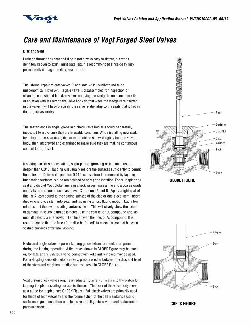
Vogt Valves Catalog and Application Manual VVENCT0000-06 08/17
138
Care and Maintenance of Vogt Forged Steel ValvesDisc and Seat
Leakage through the seat and disc is not always easy to detect, but when definitely known to exist, immediate repair is recommended since delay may permanently damage the disc, seat or both.
The internal repair of gate valves 2" and smaller is usually found to be uneconomical. However, if a gate valve is disassembled for inspection or cleaning, care should be taken when removing the wedge to note and mark its orientation with respect to the valve body so that when the wedge is reinserted in the valve, it will have precisely the same relationship to the seats that it had in the original assembly.
The seat threads in angle, globe and check valve bodies should be carefully inspected to make sure they are in usable condition. When installing new seats by using proper seat tools, the seats should be screwed tightly into the valve body, then unscrewed and examined to make sure they are making continuous contact for tight seal.
If seating surfaces show galling, slight pitting, grooving or indentations not deeper than 0.010", lapping will usually restore the surfaces sufficiently to permit tight closure. Defects deeper than 0.010" can seldom be corrected by lapping, but seating surfaces can be remachined or new parts installed. For re-lapping the seat and disc of Vogt globe, angle or check valves, uses a fine and a coarse grade emery base compound such as Clover Compound A and D. Apply a light coat of fine, or A, compound to the seating surface of the disc or one-piece stem, insert disc or one-piece stem into seat, and lap using an oscillating motion. Lap a few minutes and then wipe seating surfaces clean. This will clearly show the extent of damage. If severe damage is noted, use the coarse, or D, compound and lap until all defects are removed. Then finish with the fine, or A, compound. It is recommended that the face of the disc be “blued” to check for contact between seating surfaces after final lapping.
Globe and angle valves require a lapping guide fixture to maintain alignment during the lapping operation. A fixture as shown in GLOBE Figure may be made or, for O.S. and Y. valves, a valve bonnet with yoke nut removed may be used. For re-lapping loose disc globe valves, place a washer between the disc and head of the stem and retighten the disc nut, as shown in GLOBE Figure.
Vogt piston check valves require an adapter to screw or mate into the piston for lapping the piston seating surface to the seat. The bore of the valve body serves as a guide for lapping, see CHECK Figure. Ball check valves are primarily used for fluids of high viscosity and the rolling action of the ball maintains seating surfaces in good condition until ball size or ball guide is worn and replacement parts are needed.
GLOBE FIGURE
CHECK FIGURE
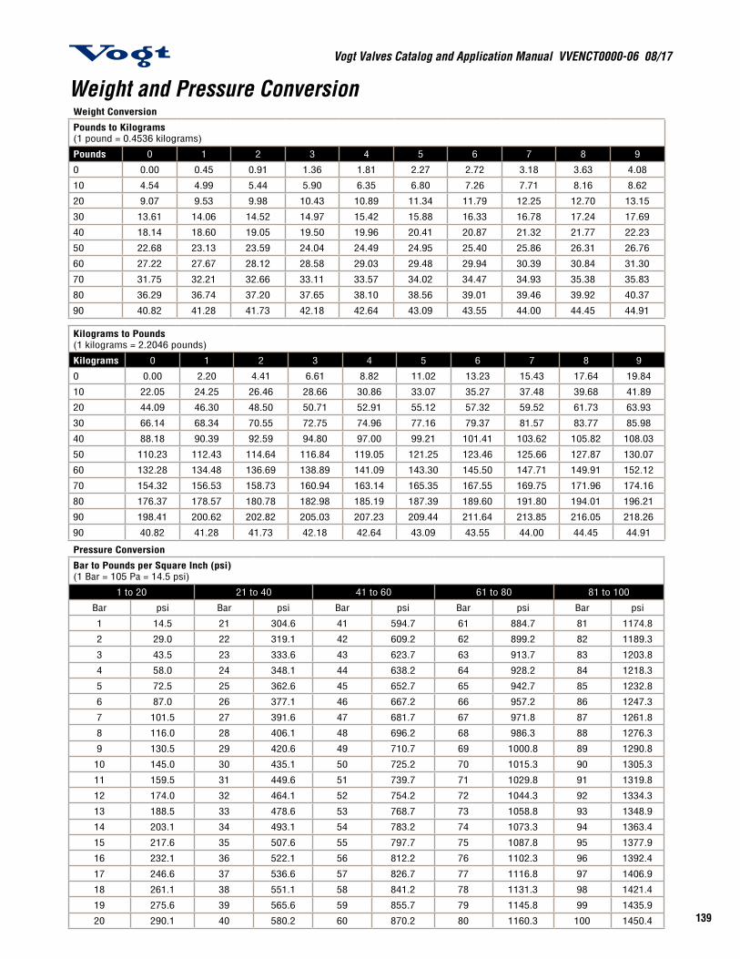
139
Vogt Valves Catalog and Application Manual VVENCT0000-06 08/17
Weight Conversion
Pounds to Kilograms (1 pound = 0.4536 kilograms)
Pounds 0 1 2 3 4 5 6 7 8 9
0 0.00 0.45 0.91 1.36 1.81 2.27 2.72 3.18 3.63 4.08
10 4.54 4.99 5.44 5.90 6.35 6.80 7.26 7.71 8.16 8.62
20 9.07 9.53 9.98 10.43 10.89 11.34 11.79 12.25 12.70 13.15
30 13.61 14.06 14.52 14.97 15.42 15.88 16.33 16.78 17.24 17.69
40 18.14 18.60 19.05 19.50 19.96 20.41 20.87 21.32 21.77 22.23
50 22.68 23.13 23.59 24.04 24.49 24.95 25.40 25.86 26.31 26.76
60 27.22 27.67 28.12 28.58 29.03 29.48 29.94 30.39 30.84 31.30
70 31.75 32.21 32.66 33.11 33.57 34.02 34.47 34.93 35.38 35.83
80 36.29 36.74 37.20 37.65 38.10 38.56 39.01 39.46 39.92 40.37
90 40.82 41.28 41.73 42.18 42.64 43.09 43.55 44.00 44.45 44.91
Kilograms to Pounds (1 kilograms = 2.2046 pounds)
Kilograms 0 1 2 3 4 5 6 7 8 9
0 0.00 2.20 4.41 6.61 8.82 11.02 13.23 15.43 17.64 19.84
10 22.05 24.25 26.46 28.66 30.86 33.07 35.27 37.48 39.68 41.89
20 44.09 46.30 48.50 50.71 52.91 55.12 57.32 59.52 61.73 63.93
30 66.14 68.34 70.55 72.75 74.96 77.16 79.37 81.57 83.77 85.98
40 88.18 90.39 92.59 94.80 97.00 99.21 101.41 103.62 105.82 108.03
50 110.23 112.43 114.64 116.84 119.05 121.25 123.46 125.66 127.87 130.07
60 132.28 134.48 136.69 138.89 141.09 143.30 145.50 147.71 149.91 152.12
70 154.32 156.53 158.73 160.94 163.14 165.35 167.55 169.75 171.96 174.16
80 176.37 178.57 180.78 182.98 185.19 187.39 189.60 191.80 194.01 196.21
90 198.41 200.62 202.82 205.03 207.23 209.44 211.64 213.85 216.05 218.26
90 40.82 41.28 41.73 42.18 42.64 43.09 43.55 44.00 44.45 44.91
Pressure Conversion
Bar to Pounds per Square Inch (psi) (1 Bar = 105 Pa = 14.5 psi)
1 to 20 21 to 40 41 to 60 61 to 80 81 to 100
Bar psi Bar psi Bar psi Bar psi Bar psi
1 14.5 21 304.6 41 594.7 61 884.7 81 1174.8
2 29.0 22 319.1 42 609.2 62 899.2 82 1189.3
3 43.5 23 333.6 43 623.7 63 913.7 83 1203.8
4 58.0 24 348.1 44 638.2 64 928.2 84 1218.3
5 72.5 25 362.6 45 652.7 65 942.7 85 1232.8
6 87.0 26 377.1 46 667.2 66 957.2 86 1247.3
7 101.5 27 391.6 47 681.7 67 971.8 87 1261.8
8 116.0 28 406.1 48 696.2 68 986.3 88 1276.3
9 130.5 29 420.6 49 710.7 69 1000.8 89 1290.8
10 145.0 30 435.1 50 725.2 70 1015.3 90 1305.3
11 159.5 31 449.6 51 739.7 71 1029.8 91 1319.8
12 174.0 32 464.1 52 754.2 72 1044.3 92 1334.3
13 188.5 33 478.6 53 768.7 73 1058.8 93 1348.9
14 203.1 34 493.1 54 783.2 74 1073.3 94 1363.4
15 217.6 35 507.6 55 797.7 75 1087.8 95 1377.9
16 232.1 36 522.1 56 812.2 76 1102.3 96 1392.4
17 246.6 37 536.6 57 826.7 77 1116.8 97 1406.9
18 261.1 38 551.1 58 841.2 78 1131.3 98 1421.4
19 275.6 39 565.6 59 855.7 79 1145.8 99 1435.9
20 290.1 40 580.2 60 870.2 80 1160.3 100 1450.4
Weight and Pressure Conversion
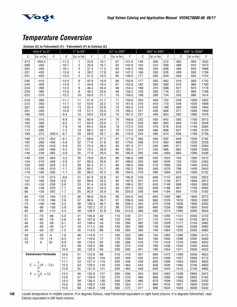
Vogt Valves Catalog and Application Manual VVENCT0000-06 08/17
140
Celsius (C) to Fahrenheit (F) - Fahrenheit (F) to Celsius (C)
-459.4° to 0° 1° to 60° 61° to 290° 300° to 890° 900° to 3000°
C Cel. or Fah. F C Cel. or Fah. F C Cel. or Fah. F C Cel. or Fah. F C Cel. or Fah. F
-273-268-262-257-251
-459.4-450-440-430-420
-17.2-16.7-16.1-15.6-15.0
12345
33.835.637.439.241.0
16.116.717.217.818.3
6162636465
141.8143.6145.4147.2149.0
149154160166171
300310320330340
572590608626644
482488493499504
900910920930940
16521670168817061724
-246-240-234-229-223
-410-400-390-380-370
-14.4-13.9-13.3-12.8-12.2
678910
42.844.646.448.250.0
18.919.420.020.621.1
6667686970
150.8152.6154.4156.2158.0
177182188193199
350360370380390
662680698716734
510516521527532
950960970980990
17421760177817961814
-218-212-207-201-196
-360-350-340-330-320
-11.7-11.1-10.6-10.0-9.4
1112131415
51.853.655.457.259.0
21.722.222.823.323.9
7172737475
159.8161.6163.4165.2167.0
204210216221227
400410420430440
752770788806824
538549560571582
10001020104010601080
18321868190419401976
-190-184-179-173-169
-310-300-290-280-273 -459.4
-8.9-8.3-7.8-7.2-6.7
1617181920
60.862.664.466.268.0
24.425.025.626.126.7
7677787980
168.8170.6172.4174.2176.0
232238243249254
450460470480490
842860878896914
593604616627638
11001120114011601180
20122048208421202156
-168-162-157-151-146
-270-260-250-240-230
-454-436-418-400-382
-6.1-5.6-5.0-4.4-3.9
2122232425
69.871.673.475.277.0
27.227.828.328.929.4
8182838485
177.8179.6181.4183.2185.0
260266271277282
500510520530540
9329509689861004
649660671682693
12001220124012601280
21922228226423002336
-140-134-129-123-118
-220-210-200-190-180
-364-346-328-310-292
-3.3-2.8-2.2-1.7-1.1
2627282930
78.880.682.484.286.0
30.030.631.131.732.2
8687888990
186.8188.6190.4192.2194.0
288293299304310
550560570580590
10221040105810761094
704732760788816
13001350140014501500
23722462255226422732
-112-107-101-96-90
-170-160-150-140-130
-274-256-238-220-202
-0.60.00.61.11.7
3132333435
87.889.691.493.295.0
32.833.333.934.435.0
9192939495
195.8197.6199.4201.2203.0
316321327332338
600610620630640
11121130114811661184
843871899927954
15501600165017001750
28222912300230923182
-84-79-73-68-62
-120-110-100-90-80
-184-166-148-130-112
2.22.83.33.94.4
3637383940
96.898.6100.4102.2104.0
35.636.136.737.237.8
96979899100
204.8206.6208.4210.2212.0
343349354360366
650660670680690
12021220123812561274
9821010103810661093
18001850190019502000
32723362345235423632
-57-51-46-40-34
-70-60-50-40-30
-94-76-58-40-22
5.05.66.16.77.2
4142434445
105.8107.6109.4111.2113.0
4349546066
110120130140150
230248266284302
371377382388393
700710720730740
12921310132813461364
11211149117712041232
20502100215022002250
37223812390239924082
-29-23-18
-20-100
-41432
7.88.38.99.410.0
4647484950
114.8116.6118.4120.2122.0
7177828893
160170180190200
320338356374392
399404410416421
750760770780790
13821400141814361454
12601288131613431371
23002350240024502500
41724262435244424532
10.611.111.712.212.8
5152535455
123.8125.6127.4129.2131.0
99104110116121
210220230240250
410428446464482
427432438443449
800810820830840
14721490150815261544
13991427145414821510
25502600265027002750
46224712480248924982
13.313.914.415.015.6
5657585960
132.8134.6136.4138.2140.0
127132138143149
260270280290300
500518536554572
454460466471477
850860870880890
15621580159816161634
15381566159316211649
28002850290029503000
50725162525253425432
3259
)32(95
�
<�
CF
FC
Conversion Formulas
Temperature Conversion
Locate temperature in middle column. If in degrees Celsius, read Fahrenheit equivalent in right hand column; if in degrees Fahrenheit, read Celsius equivalent in left hand column.
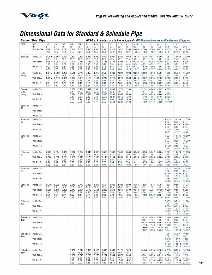
141
Vogt Valves Catalog and Application Manual VVENCT0000-06 08/17
Carbon Steel Pipe NPS-Black numbers are inches and pounds DN-Blue numbers are millimeter and kilogramsPIPE NPS
DNOutside Dia.
1/880.40510.3
1/480.54013.7
3/8100.67517.1
1/2150.84021.3
3/4201.05026.7
1251.31533.4
1 1/4321.66042.2
1 1/2401.90048.3
2502.37560.3
2 1/2652.87573.0
3803.50088.9
3 1/2954.000101.6
41004.500114.3
51255.563141.3
61506.625168.3
82008.625219.1
1025010.750273.0
1230012.750323.8
Standard Inside Dia.
Wall Thick.
Wt. Per Ft.
0.2696.80.0681.730.240.37
0.3649.20.0882.240.420.63
0.49312.50.0912.310.570.84
0.62215.80.1092.770.851.27
0.82420.90.1132.871.131.69
1.04925.60.1333.381.682.50
1.38035.10.1403.562.273.39
1.61040.90.1453.682.724.05
2.06752.50.1543.913.655.44
2.46962.70.2035.165.798.63
3.06877.90.2165.497.5811.29
3.54890.10.2265.749.1113.57
4.0261020.2376.0210.7916.07
5.0471280.2586.5514.6221.77
6.0651540.2807.1118.9728.26
7.9812030.3228.1828.5542.55
10.0202550.3659.2740.4860.31
12.0003050.3759.5349.5673.88
Extra Heavy
Inside Dia.
Wall Thick.
Wt. Per Ft.
0.2155.40.0952.410.310.47
0.3027.70.1193.020.540.80
0.42310.70.1263.200.741.10
0.54613.90.1473.731.091.62
0.74218.80.1543.911.472.20
0.95724.30.1794.552.173.24
1.27832.50.1914.853.004.47
1.5038.10.2005.083.635.41
1.93949.20.2185.545.027.48
2.32359.00.2767.017.6611.41
2.90073.70.3007.6210.2515.27
3.36485.40.3188.0812.5018.63
3.82697.20.3378.5614.9822.32
4.8131220.3759.5320.7830.97
5.7611460.43210.9728.5742.56
7.6251940.50012.7043.3964.64
9.7502480.50012.7054.7481.55
11.7502980.60012.7065.4297.46
DoubleExtra Heavy
Inside Dia.
Wall Thick.
Wt. Per Ft.
0.2526.40.2947.471.712.55
0.43411.00.3087.822.443.64
0.59915.20.3589.093.665.45
8.9622.60.3829.705.217.77
1.10027.90.40010.156.419.56
1.50336.20.43611.079.0313.44
1.7715.00.5520.55213.6920.39
2.30058.40.60015.2418.5827.68
3.15280.10.67417.1227.5441.03
4.0631030.75019.0538.5557.43
4.8971240.86421.9553.1679.22
6.8751750.87522.2372.4107.92
Schedule10
Inside Dia.
Wall Thick.
Wt. Per Ft.
Schedule20
Inside Dia.
Wall Thick.
Wt. Per Ft.
6.1252060.2506.3522.3633.31
10.2502600.2506.3528.0441.77
12.2503110.2506.3533.3849.73
Schedule30
Inside Dia.
Wall Thick.
Wt. Per Ft.
8.0712050.2777.0424.7036.81
10.1362570.3077.8034.2451.03
12.090307*0.3308.3843.7765.20
Schedule40
Inside Dia.
Wall Thick.
Wt. Per Ft.
0.2696.80.0681.730.240.32
0.3649.20.0882.240.420.63
0.49312.50.0912.310.570.84
0.62215.80.1092.770.851.27
0.82420.90.1132.871.131.69
1.04926.60.1333.381.662.50
1.38035.10.1403.562.273.39
1.61040.90.1453.682.724.05
2.06752.50.1543.913.655.44
2.46962.70.2035.165.798.63
3.06877.90.2165.497.5811.29
3.54890.10.2265.749.1113.57
4.0261020.2376.0210.7916.07
5.0471280.2586.5514.6221.77
6.0651540.2807.1118.9728.26
7.9812030.3228.1828.5542.55
10.0202550.3659.2740.4860.31
11.9383030.40610.3253.5279.73
Schedule60
Inside Dia.
Wall Thick.
Wt. Per Ft.
7.8131980.40610.3135.6453.08
9.750248+0.50012.7054.7481.55
11.6262950.56214.2773.15108.96
Schedule80
Inside Dia.
Wall Thick.
Wt. Per Ft.
0.2155.50.0952.410.310.47
0.3027.70.1193.020.540.80
0.42310.70.1263.200.741.10
0.54613.90.1473.731.091.62
0.74218.80.1543.911.472.20
0.95724.30.1794.552.173.24
1.27832.50.1914.853.004.47
1.5038.10.2005.083.635.41
1.93949.30.2185.545.027.48
2.32359.00.2767.017.6611.41
2.90073.70.3007.6210.2515.27
3.36485.40.3188.0812.5118.63
3.82697.20.3378.5614.9822.32
4.813122.3759.5320.7830.97
5.7611450.43210.9728.5742.56
7.6251940.50012.7043.3964.64
9.5642430.59415.0264.4396.01
11.3762890.68817.4888.63132.08
Schedule100
Inside Dia.
Wall Thick.
Wt. Per Ft.
7.4391890.59415.0950.9575.92
9.3142370.71918.2677.03114.75
11.0842810.84421.44107.32159.91
Schedule120
Inside Dia.
Wall Thick.
Wt. Per Ft.
3.62492.00.43811.1319.0026.32
4.5631160.50012.7027.0440.28
5.5011400.56214.2736.3954.20
7.1891830.71918.2660.7190.44
9.0642300.84421.4489.24133.06
10.752731.00025.40125.49186.97
Schedule140
Inside Dia.
Wall Thick.
Wt. Per Ft.
7.0011790.81220.6267.76100.92
8.7502221.00025.40104.13155.15
10.502671.12528.58139.67208.14
Schedule160
Inside Dia.
Wall Thick.
Wt. Per Ft.
0.46611.80.1884.781.311.95
0.61415.60.2195.561.942.90
0.81520.70.2506.352.844.24
1.16029.50.2506.353.765.61
1.33834.00.2817.144.867.25
1.68942.90.3448.747.4611.11
2.12554.00.3759.5310.0114.92
2.62456.60.43811.1314.3221.35
3.43887.30.53113.4922.5133.54
4.3131100.62515.8832.9649.11
5.1891320.71918.2645.3567.56
6.8131730.90623.0174.69111.27
8.5002161.12528.58115.64177.33
10.1262571.31233.32160.27238.76
Dimensional Data for Standard & Schedule Pipe
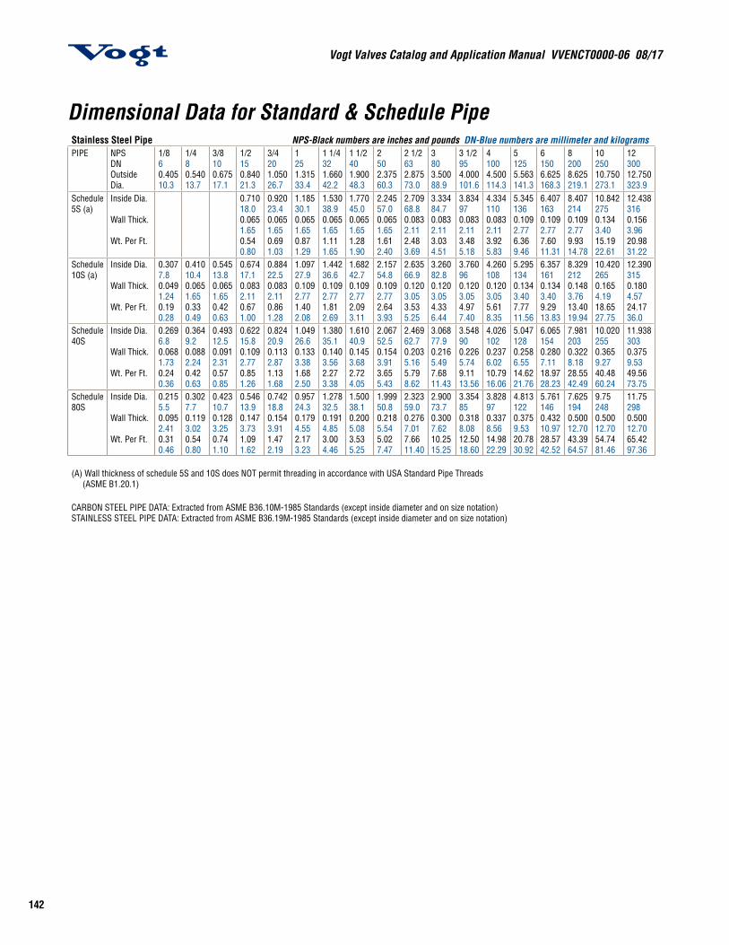
Vogt Valves Catalog and Application Manual VVENCT0000-06 08/17
142
Stainless Steel Pipe NPS-Black numbers are inches and pounds DN-Blue numbers are millimeter and kilogramsPIPE NPS
DNOutside Dia.
1/860.40510.3
1/480.54013.7
3/8100.67517.1
1/2150.84021.3
3/4201.05026.7
1251.31533.4
1 1/4321.66042.2
1 1/2401.90048.3
2502.37560.3
2 1/2632.87573.0
3803.50088.9
3 1/2954.000101.6
41004.500114.3
51255.563141.3
61506.625168.3
82008.625219.1
1025010.750273.1
1230012.750323.9
Schedule 5S (a)
Inside Dia.
Wall Thick.
Wt. Per Ft.
0.71018.00.0651.650.540.80
0.92023.40.0651.650.691.03
1.18530.10.0651.650.871.29
1.53038.90.0651.651.111.65
1.77045.00.0651.651.281.90
2.24557.00.0651.651.612.40
2.70968.80.0832.112.483.69
3.33484.70.0832.113.034.51
3.834970.0832.113.485.18
4.3341100.0832.113.925.83
5.3451360.1092.776.369.46
6.4071630.1092.777.6011.31
8.4072140.1092.779.9314.78
10.8422750.1343.4015.1922.61
12.4383160.1563.9620.9831.22
Schedule 10S (a)
Inside Dia.
Wall Thick.
Wt. Per Ft.
0.3077.80.0491.240.190.28
0.41010.40.0651.650.330.49
0.54513.80.0651.650.420.63
0.67417.10.0832.110.671.00
0.88422.50.0832.110.861.28
1.09727.90.1092.771.402.08
1.44236.60.1092.771.812.69
1.68242.70.1092.772.093.11
2.15754.80.1092.772.643.93
2.63566.90.1203.053.535.25
3.26082.80.1203.054.336.44
3.760960.1203.054.977.40
4.2601080.1203.055.618.35
5.2951340.1343.407.7711.56
6.3571610.1343.409.2913.83
8.3292120.1483.7613.4019.94
10.4202650.1654.1918.6527.75
12.3903150.1804.5724.1736.0
Schedule 40S
Inside Dia.
Wall Thick.
Wt. Per Ft.
0.2696.80.0681.730.240.36
0.3649.20.0882.240.420.63
0.49312.50.0912.310.570.85
0.62215.80.1092.770.851.26
0.82420.90.1132.871.131.68
1.04926.60.1333.381.682.50
1.38035.10.1403.562.273.38
1.61040.90.1453.682.724.05
2.06752.50.1543.913.655.43
2.46962.70.2035.165.798.62
3.06877.90.2165.497.6811.43
3.548900.2265.749.1113.56
4.0261020.2376.0210.7916.06
5.0471280.2586.5514.6221.76
6.0651540.2807.1118.9728.23
7.9812030.3228.1828.5542.49
10.0202550.3659.2740.4860.24
11.9383030.3759.5349.5673.75
Schedule 80S
Inside Dia.
Wall Thick.
Wt. Per Ft.
0.2155.50.0952.410.310.46
0.3027.70.1193.020.540.80
0.42310.70.1283.250.741.10
0.54613.90.1473.731.091.62
0.74218.80.1543.911.472.19
0.95724.30.1794.552.173.23
1.27832.50.1914.853.004.46
1.50038.10.2005.083.535.25
1.99950.80.2185.545.027.47
2.32359.00.2767.017.6611.40
2.90073.70.3007.6210.2515.25
3.354850.3188.0812.5018.60
3.828970.3378.5614.9822.29
4.8131220.3759.5320.7830.92
5.7611460.43210.9728.5742.52
7.6251940.50012.7043.3964.57
9.752480.50012.7054.7481.46
11.752980.50012.7065.4297.36
(A) Wall thickness of schedule 5S and 10S does NOT permit threading in accordance with USA Standard Pipe Threads (ASME B1.20.1)
CARBON STEEL PIPE DATA: Extracted from ASME B36.10M-1985 Standards (except inside diameter and on size notation)STAINLESS STEEL PIPE DATA: Extracted from ASME B36.19M-1985 Standards (except inside diameter and on size notation)
Dimensional Data for Standard & Schedule Pipe
143
Vogt Valves Catalog and Application Manual VVENCT0000-06 08/17
Limited WarrantySeller warrants that the Goods shall be free from defects in materials manufactured by Seller and in Seller’s workmanship for a period of one (1) year following shipment (the”Warranty Period”). This limited warranty shall apply only in favor of Buyer, shall expire on the last day of such one (1) year period and shall be subject to the following:
a. This warranty shall not apply to Goods that have been (i) repaired or altered by any Person other than the Seller, (ii) subjected to unreasonable or improper use or use beyond rated conditions, improper storage, negligence or accident, (iii) damaged because of use of the Goods or incorporation of the Goods into use of any Goods with other materials or equipment, after Buyer (or any other person using the Goods) has, or reasonably should have, knowledge of any defect; (iv) manufactured, fabricated or assembled by any person other than Seller (Seller shall assign to Buyer, to the extent same is assignable, any warranty Seller has received from the manufacture of such Goods); or (v) improperly installed by any person (including Buyer) other than Seller.
b. This warranty shall not be effective unless Seller receives a written claim within thirty (30) days after discovery of any defect with respect to which a claim is made.
c. Seller shall have the right (but not the obligation) to verify, with its own representatives, the nature and extent of any claimed defect prior to return of Goods to Seller. Upon request by Seller, Buyer shall, at its own risk and expense, promptly return the Goods in question to Seller’s Plant.
d. Buyer covenants to inform all subsequent buyers to the Goods of the limitations on and exclusion of the warranties provided herein. Buyer hereby indemnifies and agrees to hold Seller harmless from and against all losses, costs and expenses, including reasonable attorney’s fees incurred by Seller as a result of any third-party claim relating to the purchase, sale or use of, otherwise relating to, the Goods covered by this agreement.
e. Seller’s liability for any breach of warranty shall be limited either to (i) repair or replacement (whichever Seller shall elect) at Seller’s Plant of any Goods determined by Seller to be defective, or (ii) payment of an amount equal to the invoiced cost to the Buyer of the part or material that is defective, as Seller may elect. In no event shall Seller be required to repair, replace or reimburse Buyer for more that the part or material that is found to be defective and Seller’s liability shall in no event be greater than the invoiced price of the item and shall not include labor, shipping or other costs incurred in connection with the reshipment of defective Goods to Seller or the reinstallation of such Goods after any repair or replacement. The Goods, as a whole, shall not be construed to be a “part” or “material” for the purpose of the immediately preceding sentence. Any Goods that are repaired or replaced by Seller shall be re-delivered to Buyer F.O.B. Seller’s Plant and shall be warranted for the remaining term of the original Warranty Period for such Goods. THE REMEDY SET FORTH IN THIS LIMITED WARRANTY IS EXPRESSLY AGREED TO BE SOLE AND EXCLUSIVE REMEDY FOR ANY SUCH BREACH OF WARRANTY.
f. THIS LIMITED WARRANTY IS IN LIEU OF ALL OTHER WARRANTIES (EXCEPT OF TITLE), EXPRESS, IMPLIED OR STATUTORY, INCLUDING WITHOUT LIMITATION ANY IMPLIED OR EXPRESS WARRANTIES OF MERCHANTABILITY, FITNESS FOR A PARTICULAR PURPOSE AND CONFORMITY TO MODELS OR SAMPLES. ALL OTHER LIABILITY WHETHER IN CONTRACT OR TORT, STRICT LIABILITY, NEGLIGENCE OR OTHERWISE, IS HEREBY EXCLUDED.
144
www.vogtvalves.comA Member Of OMB Valve Group