catalogue 2017/2018 vemodrive frequency converter vsi2 · the vemodrive frequency converter vsi2.0...
TRANSCRIPT

Catalogue 2017/2018
VEMoDRIVEFrequency Converter VSI2.0VEMoDRIVE Single – Low voltage0,55 kW – 3000 kW
There are currently around 30 million electric ma-
chines bearing the VEM badge in use around the
world. They are found aboard ships, in trains and
trams, and in chemical plants and rolling mills.
VEM generators produce electricity in hydropower
plants and wind farms.
The VEM product range embraces variable-speed
electric drive systems, special motors and special
machines for outputs ranging from 0.06 kW to
42 MW, as well as a diversity of drive technology
and power generation components.
Transportation
Machine and plant engineering
Steel and rolling mills
Cement and mining industry
Shipbuilding
Chemical, oil and gas industry
Water management
Renewable energy
Power plant technology
3
VE
MoD
RIV
E F
requ
ency
Con
vert
er V
SI2
.0 |
VE
MoD
RIV
E S
ingl
e –
Low
vol
tage
Contents
VEMoDRIVE frequency converter VSI2.0 5
Type designation 6
General overview 7
Frequency converters for every application: VEMoDRIVE VSI2.0 7
High dynamic response for demanding applications: VEMoDRIVE VSI2.0-HD 8
Energy savings for pumps and fans: VEMoDRIVE VSI2.0-SD 8
Low mains pollution and power regeneration capabilities: VEMoDRIVE VSI2.0-LH/RP 8
12-pulse version – reduced mains pollution with diode front end: VEMoDRIVE VSI2.0CSB 8
Notes on configuration of VEMoDRIVE frequency converters 8
Technical data 9
VEMoDRIVE VSI2.0 – HD (High Dynamic) 9
VEMoDRIVE VSI2.0 – SD (Standard Dynamic) 13
VEMoDRIVE VSI2.0 – LH/RP (Low Harmonic/Regenerative Power) 17
General data ________________________________________________________________________________________________________ 18
Electrical parameters 18
Ambient conditions for normal operation 18
Derating 18
Operation at higher temperatures 18
Installation altitude 18
Storage conditions 19
Product conformity 19
Standards and regulations 19
Europe 19
General applicability 19
North and South America 19
Russia 19
Design versions 20
Control precision of VEMoDRIVE VSI2.0-HD (High Dynamic) 22
Control precision of VEMoDRIVE VSI2.0-SD (Standard Dynamic) 22
Interfaces 23
Overview 23
Parameters of input and output channels 24
Contents
Page
VEMoDRIVE Frequency Converter VSI2.0 VEMoDRIVE Single – Low voltage
0.55 kW – 3000 kW

4
VE
MoD
RIV
E F
requ
ency
Con
vert
er V
SI2
.0 |
VE
MoD
RIV
E S
ingl
e –
Low
vol
tage
Seite
Options for the frequency converter VSI2.0 25
Overview 25
Function boards 26
Communication boards: Field bus and Ethernet 26
Filters 27
Selection matrix 27
Enhanced EMC filter category C2 28
Output reactors 28
Overvoltage feedback 28
Sine-wave filters 29
Common mode filters 29
Control panels 30
Further options 30
Braking resistors – Notes on configuration 30
Liquid cooling 31
DC link reactors 31
Circuit-breaker instead of switch-disconnector 31
12-pulse version 31
Contents
VEMoDRIVE Frequency Converter VSI2.0 VEMoDRIVE Single – Low voltage
0.55 kW – 3000 kW
Contents

5
VE
MoD
RIV
E F
requ
ency
Con
vert
er V
SI2
.0 |
VE
MoD
RIV
E S
ingl
e –
Low
vol
tage
The VEMoDRIVE frequency converter VSI2.0 meets the requirements of a broad diversity of industrial applications. The main fields of application are variable-speed drives for
– pumps– fans– rotary kilns– conveyors– choppers and refiners– compressors– crane systems and lifts
VEMoDRIVE frequency converter VSI2.0
VEMoDRIVE frequency converters can be supplied either for wall mounting or as ready-assembled cabinet systems. They cover an output range from 0.55 kW to 3 MW and can be supplied with input voltages from 230 to 690 V, depending on the series and output class.
Your benefits:– Consistent, user-friendly operating concept – Degree of protection IP 20, IP 21, IP 23 and IP 54,
depending on the series – Air and liquid cooling– Service-friendly modular design– Integrated EMC mains filter (industrial)
VEMoDRIVE frequency converter VSI2.0
– mixers– grinding mills– test benches– sifters– winders– centrifuges
6
VE
MoD
RIV
E F
requ
ency
Con
vert
er V
SI2
.0 |
VE
MoD
RIV
E S
ingl
e –
Low
vol
tage
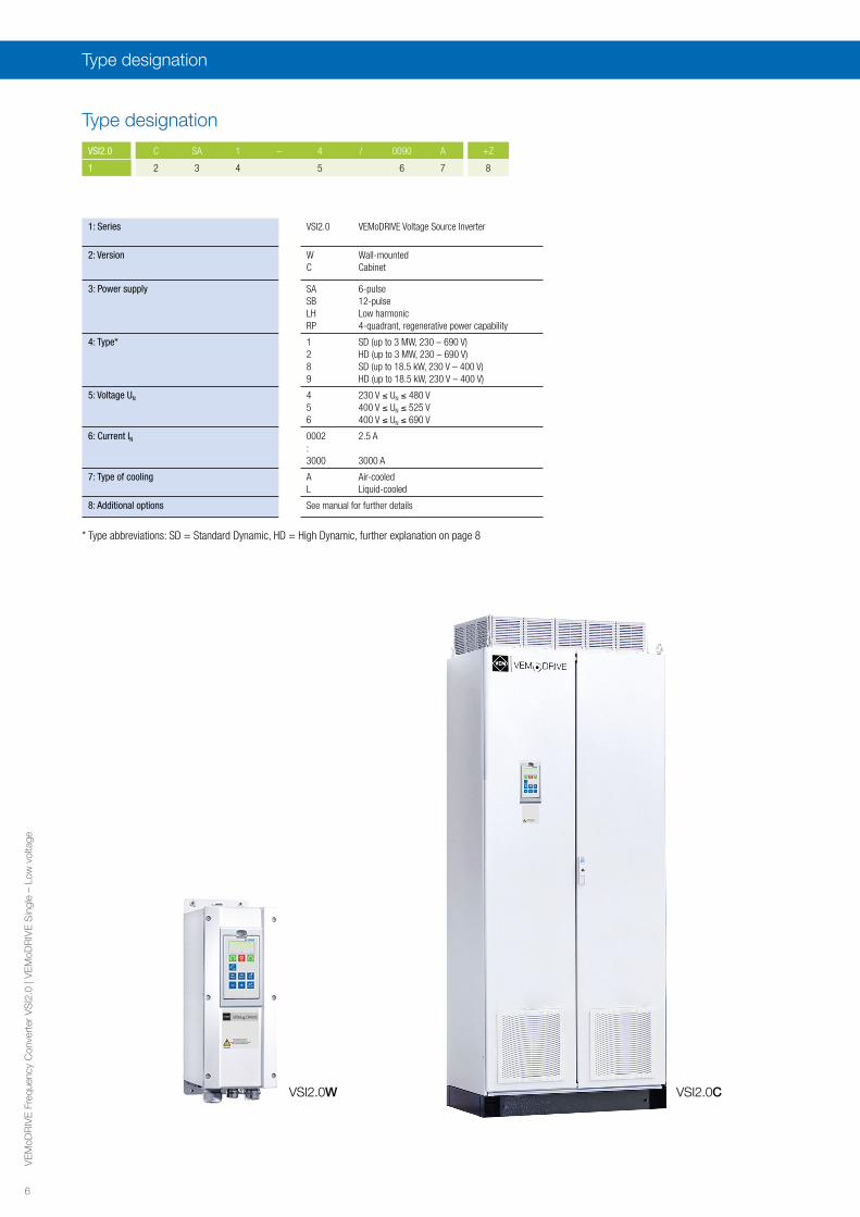
Type designation
Type designation
VSI2.0 C SA 1 – 4 / 0090 A +Z
1 2 3 4 5 6 7 8
VSI2.0C VSI2.0W
* Type abbreviations: SD = Standard Dynamic, HD = High Dynamic, further explanation on page 8
1: Series VSI2.0 VEMoDRIVE Voltage Source Inverter
2: Version W Wall-mountedC Cabinet
3: Power supply SA 6-pulseSB 12-pulseLH Low harmonicRP 4-quadrant, regenerative power capability
4: Type* 1 SD (up to 3 MW, 230 – 690 V)2 HD (up to 3 MW, 230 – 690 V)8 SD (up to 18.5 kW, 230 V – 400 V)9 HD (up to 18.5 kW, 230 V – 400 V)
5: Voltage UN 4 230 V ≤ UN ≤ 480 V5 400 V ≤ UN ≤ 525 V6 400 V ≤ UN ≤ 690 V
6: Current IN 0002 2.5 A:3000 3000 A
7: Type of cooling A Air-cooledL Liquid-cooled
8: Additional options See manual for further details
7
VE
MoD
RIV
E F
requ
ency
Con
vert
er V
SI2
.0 |
VE
MoD
RIV
E S
ingl
e –
Low
vol
tage
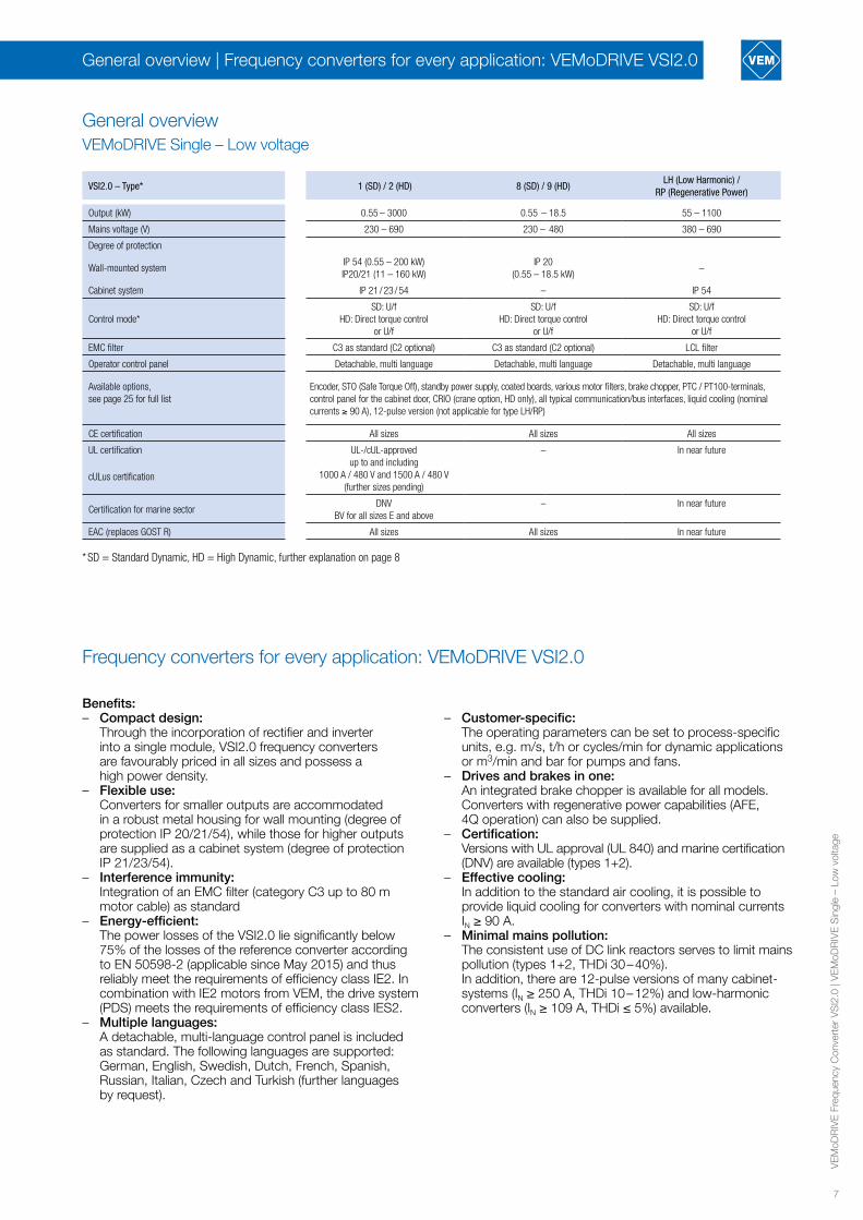
General overview | Frequency converters for every application: VEMoDRIVE VSI2.0
VSI2.0 – Type* 1 (SD) / 2 (HD) 8 (SD) / 9 (HD)LH (Low Harmonic) /
RP (Regenerative Power)
Output (kW) 0.55 – 3000 0.55 – 18.5 55 – 1100
Mains voltage (V) 230 – 690 230 – 480 380 – 690
Degree of protection
Wall-mounted systemIP 54 (0.55 – 200 kW)IP20/21 (11 – 160 kW)
IP 20(0.55 – 18.5 kW)
–
Cabinet system IP 21 / 23 / 54 – IP 54
Control mode*SD: U/f
HD: Direct torque control or U/f
SD: U/fHD: Direct torque control
or U/f
SD: U/fHD: Direct torque control
or U/f
EMC filter C3 as standard (C2 optional) C3 as standard (C2 optional) LCL filter
Operator control panel Detachable, multi language Detachable, multi language Detachable, multi language
Available options,see page 25 for full list
Encoder, STO (Safe Torque Off), standby power supply, coated boards, various motor filters, brake chopper, PTC / PT100-terminals, control panel for the cabinet door, CRIO (crane option, HD only), all typical communication/bus interfaces, liquid cooling (nominal currents ≥ 90 A), 12-pulse version (not applicable for type LH/RP)
CE certification All sizes All sizes All sizes
UL certification UL-/cUL-approved up to and including
1000 A / 480 V and 1500 A / 480 V (further sizes pending)
– In near future
cULus certification
Certification for marine sectorDNV
BV for all sizes E and above– In near future
EAC (replaces GOST R) All sizes All sizes In near future
General overviewVEMoDRIVE Single – Low voltage
* SD = Standard Dynamic, HD = High Dynamic, further explanation on page 8
Frequency converters for every application: VEMoDRIVE VSI2.0
Benefits:– Compact design: Through the incorporation of rectifier and inverter
into a single module, VSI2.0 frequency converters are favourably priced in all sizes and possess a high power density.
– Flexible use: Converters for smaller outputs are accommodated
in a robust metal housing for wall mounting (degree of protection IP 20/21/54), while those for higher outputs are supplied as a cabinet system (degree of protection IP 21/23/54).
– Interference immunity: Integration of an EMC filter (category C3 up to 80 m
motor cable) as standard– Energy-efficient: The power losses of the VSI2.0 lie significantly below
75% of the losses of the reference converter according to EN 50598-2 (applicable since May 2015) and thus reliably meet the requirements of efficiency class IE2. In combination with IE2 motors from VEM, the drive system (PDS) meets the requirements of efficiency class IES2.
– Multiple languages: A detachable, multi-language control panel is included
as standard. The following languages are supported: German, English, Swedish, Dutch, French, Spanish, Russian, Italian, Czech and Turkish (further languages by request).
– Customer-specific: The operating parameters can be set to process-specific
units, e.g. m/s, t/h or cycles/min for dynamic applications or m3/min and bar for pumps and fans.
– Drives and brakes in one: An integrated brake chopper is available for all models.
Converters with regenerative power capabilities (AFE, 4Q operation) can also be supplied.
– Certification: Versions with UL approval (UL 840) and marine certification
(DNV) are available (types 1+2).– Effective cooling: In addition to the standard air cooling, it is possible to
provide liquid cooling for converters with nominal currents IN ≥ 90 A.
– Minimal mains pollution: The consistent use of DC link reactors serves to limit mains
pollution (types 1+2, THDi 30 – 40%). In addition, there are 12-pulse versions of many cabinet-
systems (IN ≥ 250 A, THDi 10 – 12%) and low-harmonic converters (IN ≥ 109 A, THDi ≤ 5%) available.

8
VE
MoD
RIV
E F
requ
ency
Con
vert
er V
SI2
.0 |
VE
MoD
RIV
E S
ingl
e –
Low
vol
tage
VEMoDRIVE frequency converters of the HD series function with direct torque control. This enables highly dynamic torque settings and precise speed control. Even without the optionally available brake chopper, the HD models possess a vector braking function (braking
High dynamic response for demanding applications: VEMoDRIVE VSI2.0-HD
power realised in the motor). The HD series is thus an ideal solution for demanding applications such as test stands, cranes, crushers, grinding mills, mixers and centrifuges.
Frequency converters for every application: VEMoDRIVE VSI2.0
VEMoDRIVE frequency converters of the favourably priced SD series were developed specifically for drives in pump, fan and compressor applications. The converter provides for continuous adaptation of the motor speed to the required output, which serves to minimise both energy consumption and wear. The intelligent monitoring function protects your processes against damage and unplanned downtimes.
Further benefits for your application:– Soft starting minimises the starting current and adjustable
speed ramps avoid pressure shocks.– In addition to the controlled motor, a VSI2.0-SD
converter is able to switch six further pump or fan motors via contactors in accordance with the desired flow rate (with the optional I/O board). An energy-saving function switches the individual motors off automatically if they are not required in order to maintain the desired pressure or flow rate.
– Numerous process-specific functions are already integrated into the VSI2.0-SD, e.g. operation at maximum speed at defined intervals in order to flush out accumulated sludge.
Energy savings for pumps and fans: VEMoDRIVE VSI2.0-SD
Notes on configuration for pumps and fan drives: With rotary pumps and fans, a higher drive speed often enables the use of a smaller driven machine with better efficiency. Most pumps and fans can be operated at speeds above their rated speed without problems, provided the specified maximum speed is not exceeded.
Generally, the power factor and often also the efficiency of a motor will be better with a smaller number of poles. This often allows for a smaller converter with reduced losses. The total heat loss of the overall drive system is thus lower, and energy costs can also be reduced significantly.
VEMoDRIVE frequency converters of the LH series (Low Harmonic) drive your motors reliably wherever high demands are to be met with regard to mains-side current harmonics (THDi ≤ 5% acc. to IEEE-519). In addition to the benefit of low mains pollution, the power regeneration capabilities of the frequency converters of the RP series permit frequent operation in braking mode or even permanent energy recovery for input to the grid. The elimination of braking resistors reduces the required cooling performance and saves energy costs.
Low mains pollution and power regeneration capabilities: VEMoDRIVE VSI2.0-LH/RP
Alongside drive control, the LH and RP series also provide for mains-side power factor correction. The voltage boost from the active front end (AFE) enables the full motor power to be made available even through voltage dips by up to 15%, or else you can operate your drives with full torque at 20% higher speeds.Both series (LH+RP) are supplied both in Standard Dynamic (SD) versions for pump and fan drives and in High Dynamic (HD) versions for demanding applications.
The recommended rated motor power PMotor specified in the following tables applies for asynchronous motors (VEM squirrel-cage motors, IE2, 4-pole) in full-load operation.
Notes on configuration of VEMoDRIVE frequency converters
In case of deviating operating conditions, the converter should be selected in accordance with the required motor current, overload current and overload time.
The 12-pulse version combined with a three-winding transformer allows you to reduce the mains-side THDi from 30 – 40% (6-pulse) to 10 – 12% (more details on page 31). The VSI2.0CSB have the same performance data as the
12-pulse version – reduced mains pollution with diode front end: VEMoDRIVE VSI2.0CSB
converters with 6-pulse diode front end VSI2.0CSA. Only the dimensions and weight of the cabinets change, see pages 12 and 16.
9
VE
MoD
RIV
E F
requ
ency
Con
vert
er V
SI2
.0 |
VE
MoD
RIV
E S
ingl
e –
Low
vol
tage
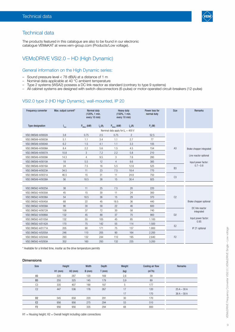
The products featured in this catalogue are also to be found in our electronic catalogue VEMeKAT at www.vem-group.com (Products/Low voltage).
Technical data
Frequency converter Max. output current* Normal duty(120%, 1 min. every 10 min)
Heavy duty (150%, 1 min. every 10 min)
Power loss for normal duty
Size Remarks
Type designation Imax PMotor (kW) IN (A) PMotor (kW) IN (A) PV (W)
Nominal data apply for Un = 400 V
VSI2.0WSA9-4/0002A 3.8 0.75 2.5 0.75 2 52.5
A3 Brake chopper integrated
Line reactor optional
Input power factor: 0.7 – 0.8
VSI2.0WSA9-4/0003A 5.1 1.1 3.4 1.1 2.7 77
VSI2.0WSA9-4/0004A 6.2 1.5 4.1 1.1 3.3 105
VSI2.0WSA9-4/0006A 8.4 2.2 5.6 1.5 4.5 154
VSI2.0WSA9-4/0007A 10.8 3 7.2 2.2 5.8 210
VSI2.0WSA9-4/0009A 14.3 4 9.5 3 7.6 280
VSI2.0WSA9-4/0010A 18 5.5 12 4 9.6 385
VSI2.0WSA9-4/0016A 24 7.5 16 5.5 12.8 525B3
VSI2.0WSA9-4/0023A 34.5 11 23 7.5 18.4 770
VSI2.0WSA9-4/0031A 46.5 15 31 11 24.8 750C3
VSI2.0WSA9-4/0038A 56 18.5 38 15 30.4 925
VSI2.0WSA2-4/0025A 38 11 25 7.5 20 220
C2
Brake chopper optional
DC link reactor integrated
Input power factor: 0.95
IP 21 optional
VSI2.0WSA2-4/0030A 45 15 30 11 24 300
VSI2.0WSA2-4/0036A 54 18.5 36 15 29 370
VSI2.0WSA2-4/0045A 68 22 45 18.5 36 440
VSI2.0WSA2-4/0058A 90 30 58 22 46 600
VSI2.0WSA2-4/0072A 108 37 72 30 58 740
D2VSI2.0WSA2-4/0088A 132 45 88 37 70 900
VSI2.0WSA2-4/0105A 132 55 105 45 85 1.100
VSI2.0WSA2-4/0142A 170 75 142 55 114 1.500E2
VSI2.0WSA2-4/0171A 205 90 171 75 137 1.800
VSI2.0WSA2-4/0205A 246 110 205 90 164 2.200
F2VSI2.0WSA2-4/0244A 293 132 244 110 195 2.640
VSI2.0WSA2-4/0293A 352 160 293 132 235 3.200
* Available for a limited time, insofar as the drive temperature permits
Dimensions
Size Height Width Depth Weight Cooling air flow Remarks
H1 (mm) H2 (mm) B (mm) T (mm) (kg) (m3/h)
A3 220 287 120 169 2,6 39
B3 255 325 145 179 3,9 89
C3 335 407 190 187 5 177
C2 447 536 176 267 17 120 25 A – 30 A
17 170 36 A – 58 A
D2 545 658 220 291 30 170
E2 956 956 275 294 53 510
F2 956 956 335 294 68 800
H1 = Housing height; H2 = Overall height including cable connections
Technical data
VSI2.0 type 2 (HD High Dynamic), wall-mounted, IP 20
General information on the High Dynamic series:
– Sound pressure level < 78 dB(A) at a distance of 1 m – Nominal data applicable at 40 °C ambient temperature– Type 2 systems (WSA2) possess a DC link reactor as standard (contrary to type 9 systems)– All cabinet systems are designed with switch-disconnectors (6-pulse) or motor-operated circuit-breakers (12-pulse)
VEMoDRIVE VSI2.0 – HD (High Dynamic)
10
VE
MoD
RIV
E F
requ
ency
Con
vert
er V
SI2
.0 |
VE
MoD
RIV
E S
ingl
e –
Low
vol
tage
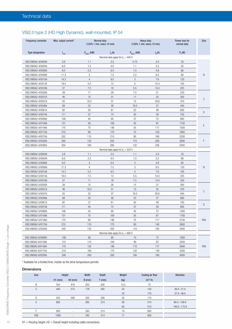
Technical data
VSI2.0 type 2 (HD High Dynamic), wall-mounted, IP 54
Frequency converter Max. output current* Normal duty (120% 1 min. every 10 min)
Heavy duty (150% 1 min. every 10 min)
Power loss for normal duty
Size
Type designation Imax PMotor (kW) IN (A) PMotor (kW) IN (A) PV (W)
Nominal data apply for Un = 400 V
VSI2.0WSA2-4/0003A 3.8 1.1 2.5 0.75 2.0 33
B
VSI2.0WSA2-4/0004A 6.0 1.5 4.0 1.1 3.2 45
VSI2.0WSA2-4/0006A 9.0 2.2 6.0 1.5 4.8 66
VSI2.0WSA2-4/0008A 11.3 3 7.5 2.2 6.0 90
VSI2.0WSA2-4/0010A 14.3 4 9.5 3 7.6 120
VSI2.0WSA2-4/0013A 19.5 5.5 13 4 10.4 165
VSI2.0WSA2-4/0018A 27 7.5 18 5.5 14.4 225
VSI2.0WSA2-4/0026A 39 11 26 7.5 21 220
CVSI2.0WSA2-4/0031A 46 15 31 11 25 300
VSI2.0WSA2-4/0037A 55 18.5 37 15 29.6 370
VSI2.0WSA2-4/0046A 69 22 46 18.5 37 440
VSI2.0WSA2-4/0061A 92 30 61 22 49 600D
VSI2.0WSA2-4/0074A 111 37 74 30 59 740
VSI2.0WSA2-4/0090A 108 45 90 37 72 900
EVSI2.0WSA2-4/0109A 131 55 109 45 87 1100
VSI2.0WSA2-4/0146A 175 75 146 55 117 1500
VSI2.0WSA2-4/0175A 210 90 175 75 140 1800
VSI2.0WSA2-4/0210A 252 110 210 90 168 2200
FVSI2.0WSA2-4/0250A 300 132 250 110 200 2640
VSI2.0WSA2-4/0295A 354 160 295 132 236 3200
Nominal data apply for Un = 525 V
VSI2.0WSA2-5/0003A 3.8 1.1 2.5 1.1 2.0 33
B
VSI2.0WSA2-5/0004A 6.0 2.2 4.0 1.5 3.2 66
VSI2.0WSA2-5/0006A 9.0 3 6.0 3 4.8 90
VSI2.0WSA2-5/0008A 11.3 4 7.5 3 6.0 120
VSI2.0WSA2-5/0010A 14.3 5.5 9.5 4 7.6 165
VSI2.0WSA2-5/0013A 19.5 7.5 13 5.5 10.4 225
VSI2.0WSA2-5/0018A 27 11 18 7.5 14.4 330
VSI2.0WSA2-5/0026A 39 15 26 15 21 300
CVSI2.0WSA2-5/0031A 46 18.5 31 15 25 370
VSI2.0WSA2-5/0037A 55 22 37 18.5 29.6 440
VSI2.0WSA2-5/0046A 69 30 46 22 37 600
VSI2.0WSA2-5/0061A 92 37 61 30 49 740D
VSI2.0WSA2-5/0074A 111 45 74 37 59 900
VSI2.0WSA2-5/0090A 108 55 90 45 72 1200
F69
VSI2.0WSA2-5/0109A 131 75 109 55 87 1700
VSI2.0WSA2-5/0146A 175 90 146 75 117 2100
VSI2.0WSA2-5/0175A 210 110 175 90 140 2600
VSI2.0WSA2-5/0200A 240 132 200 110 160 3300
Nominal data apply for Un = 690 V
VSI2.0WSA2-6/0090A 108 90 90 75 72 1800
F69
VSI2.0WSA2-6/0109A 131 110 109 90 87 2200
VSI2.0WSA2-6/0146A 175 132 146 110 117 2640
VSI2.0WSA2-6/0175A 210 160 175 132 140 3200
VSI2.0WSA2-6/0200A 240 200 200 160 160 4000
H1 = Housing height; H2 = Overall height including cable connections
Dimensions
Size Height Width Depth Weight Cooling air flow Remarks
H1 (mm) H2 (mm) B (mm) T (mm) (kg) (m3 / h)
B 350 416 203 200 12,5 75
C 440 512 178 292 24 120 26 A – 31 A
24 170 37 A – 46 A
D 545 590 220 295 32 170
E 950 - 285 314 56 510 90 A – 109 A
60 510 146 A – 175 A
F 950 - 345 314 74 800
F69 1090 - 345 314 77 800
* Available for a limited time, insofar as the drive temperature permits

11
VE
MoD
RIV
E F
requ
ency
Con
vert
er V
SI2
.0 |
VE
MoD
RIV
E S
ingl
e –
Low
vol
tage
VSI2.0 type 2 (HD High Dynamic), cabinet system, IP 21/23/54
Frequency converter Max. output current* Normal duty (120%, 1 min. every 10 min)
Heavy duty (150%, 1 min. every 10 min)
Power loss for normal duty
Size
Type designation Imax PMotor (kW) IN (A) PMotor (kW) IN (A) PV (kW) **
Nominal data apply for Un = 400 V
VSI2.0CSA2-4/0375A 450 200 375 160 300 4 G (2)
VSI2.0CSA2-4/0430A 516 220 430 200 344 4.4H (2)
VSI2.0CSA2-4/0500A 600 250 500 220 400 5
VSI2.0CSA2-4/0600A 720 315 600 250 480 6.3
I (3)VSI2.0CSA2-4/0650A 780 355 650 300 520 7.1
VSI2.0CSA2-4/0750A 900 400 750 355 600 8
VSI2.0CSA2-4/0860A 1032 450 860 400 688 9J (4)
VSI2.0CSA2-4/1000A 1200 560 1000 450 800 11.2
VSI2.0CSA2-4/1150A 1380 630 1150 500 920 12.6KA (5)
VSI2.0CSA2-4/1250A 1500 710 1250 560 1000 14.2
VSI2.0CSA2-4/1350A 1620 710 1350 600 1080 14.2K (6)
VSI2.0CSA2-4/1500A 1800 800 1500 630 1200 16
VSI2.0CSA2-4/1750A 2100 900 1750 800 1400 18 L (7)
VSI2.0CSA2-4/2000A 2400 1120 2000 900 1600 22.4 M (8)
VSI2.0CSA2-4/2250A 2700 1250 2250 1000 1800 25 N (9)
VSI2.0CSA2-4/2500A 3000 1400 2500 1120 2000 28 O (10)
Nominal data apply for Un = 525 V
VSI2.0CSA2-5/0250A 300 160 250 132 200 4
H69 (2)VSI2.0CSA2-5/0300A 360 220 300 160 240 5.5
VSI2.0CSA2-5/0375A 450 250 375 220 300 6.3
VSI2.0CSA2-5/0400A 480 300 400 220 320 7.5
VSI2.0CSA2-5/0430A 516 315 430 250 344 8
I69 (3)VSI2.0CSA2-5/0500A 600 355 500 300 400 9
VSI2.0CSA2-5/0600A 720 400 600 355 480 10
VSI2.0CSA2-5/0650A 780 450 650 355 520 11
J69 (4)VSI2.0CSA2-5/0720A 864 500 720 400 576 13
VSI2.0CSA2-5/0800A 960 560 800 450 640 14
VSI2.0CSA2-5/0900A 1080 630 900 500 720 16KA69 (5)
VSI2.0CSA2-5/1000A 1200 710 1000 560 800 18
VSI2.0CSA2-5/1200A 1440 900 1200 710 960 23 K69 (6)
VSI2.0CSA2-5/1400A 1680 1000 1400 800 1120 25 L69 (7)
VSI2.0CSA2-5/1600A 1920 1200 1600 900 1280 30 M69 (8)
VSI2.0CSA2-5/1800A 2160 1300 1800 1100 1440 33 N69 (9)
VSI2.0CSA2-5/2000A 2400 1500 2000 1200 1600 38 O69 (10)
VSI2.0CSA2-5/2200A 2640 1600 2200 1300 1760 40 P69 (11)
VSI2.0CSA2-5/2400A 2880 1800 2400 1400 1920 45 Q69 (12)
VSI2.0CSA2-5/2600A 3120 1900 2600 1500 2080 48 R69 (13)
VSI2.0CSA2-5/2800A 3360 2100 2800 1600 2240 53 S69 (14)
VSI2.0CSA2-5/3000A 3600 2200 3000 1800 2400 55 T69 (15)
Nominal data apply for Un = 690 V
VSI2.0CSA2-6/0250A 300 250 250 200 200 5
H69 (2)VSI2.0CSA2-6/0300A 360 315 300 250 240 6.3
VSI2.0CSA2-6/0375A 450 355 375 300 300 7.1
VSI2.0CSA2-6/0400A 480 400 400 315 320 8
VSI2.0CSA2-6/0430A 516 400 430 315 344 8
I69 (3)VSI2.0CSA2-6/0500A 600 450 500 355 400 9
VSI2.0CSA2-6/0600A 720 600 600 450 480 12
VSI2.0CSA2-6/0650A 780 630 650 500 520 12.6
J69 (4)VSI2.0CSA2-6/0720A 864 710 720 560 576 14.2
VSI2.0CSA2-6/0800A 960 800 800 630 640 16
VSI2.0CSA2-6/0900A 1080 900 900 710 720 18KA69 (5)
VSI2.0CSA2-6/1000A 1200 1000 1000 800 800 20
VSI2.0CSA2-6/1200A 1440 1200 1200 950 960 24 K69 (6)
VSI2.0CSA2-6/1400A 1680 1400 1400 1120 1120 28 L69 (7)
VSI2.0CSA2-6/1600A 1920 1600 1600 1250 1280 32 M69 (8)
VSI2.0CSA2-6/1800A 2160 1800 1800 1400 1440 36 N69 (9)
VSI2.0CSA2-6/2000A 2400 2000 2000 1600 1600 40 O69 (10)
VSI2.0CSA2-6/2200A 2640 2200 2200 1700 1760 44 P69 (11)
VSI2.0CSA2-6/2400A 2880 2400 2400 1900 1920 48 Q69 (12)
Technical data

12
VE
MoD
RIV
E F
requ
ency
Con
vert
er V
SI2
.0 |
VE
MoD
RIV
E S
ingl
e –
Low
vol
tage
Frequency converter Max. output current* Normal duty (120%, 1 min. every 10 min)
Heavy duty (150%, 1 min. every 10 min)
Power loss for normal duty
Size
Type designation Imax PMotor (kW) IN (A) PMotor (kW) IN (A) PV (kW) **
VSI2.0CSA2-6/2600A 3120 2600 2600 2100 2080 52 R69 (13)
VSI2.0CSA2-6/2800A 3360 2800 2800 2200 2240 56 S69 (14)
VSI2.0CSA2-6/3000A 3600 3000 3000 2400 2400 60 T69 (15)
* Available for a limited time, insofar as the drive temperature permits ** Figure in brackets, e.g. H (2), indicates the number of parallel power modules (PEBBs, Power Electronic Building Blocks)
Dimensions
Size Cooling air flow Dimensions Weight
(m3 / h) H = 2250 mm, D = 600 mmWidth (mm)
(kg)
6-pulse 12-pulse 6-pulse 12-pulse
G 1020 1000 1400 452 Upon request
H 1600 1000 1400 472 Upon request
I 2400 1300 - 617 -
J 3200 1600 2000 790 Upon request
KA 4000 2100 - 931 -
K 4800 2400 2600 1154 Upon request
L 5600 2700 - 1289 -
M 6400 Upon request 3600 Upon request Upon request
N 7200 Upon request - Upon request -
O 8000 Upon request 4200 Upon request Upon request
H69 1600 1000 1400 510 620
I69 2400 1300 - 674 -
J69 3200 1600 2000 820 920
KA69 4000 1900 - 1020 -
K69 4800 2400 2600 1264 1323
L69 5600 2700 - 1472 -
M69 6400 3000 3600 1592 1897
N69 7200 Upon request - Upon request -
O69 8000 Upon request 4200 Upon request 2171
P69 8800 Upon request - Upon request -
Q69 9600 Upon request 4800 Upon request 2788
R69 10400 Upon request - Upon request -
S69 11200 Upon request 5600 Upon request 3187
T69 12000 Upon request - Upon request -
Technical data
13
VE
MoD
RIV
E F
requ
ency
Con
vert
er V
SI2
.0 |
VE
MoD
RIV
E S
ingl
e –
Low
vol
tage
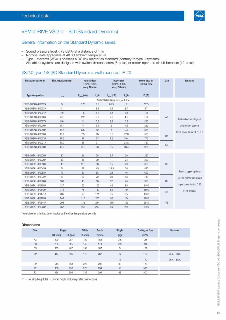
Frequency converter Max. output current* Normal duty(120%, 1 min. every 10 min)
Heavy duty(150%, 1 min. every 10 min)
Power loss for normal duty
Size Remarks
Type designation Imax PMotor (kW) IN (A) PMotor (kW) IN (A) PV (W)
Nominal data apply for U
n = 400 V
VSI2.0WSA8-4/0002A 3 0.75 2.5 0.75 2 52.5
A3Brake chopper integriert
Line reactor optional
Input power factor: 0.7 – 0.8
VSI2.0WSA8-4/0003A 4.1 1.1 3.4 1.1 2.7 77
VSI2.0WSA8-4/0004A 4.9 1.5 4.1 1.5 3.3 105
VSI2.0WSA8-4/0006A 6.7 2.2 5.6 2.2 4.5 154
VSI2.0WSA8-4/0007A 8.6 3 7.2 2.2 5.8 210
VSI2.0WSA8-4/0009A 11.4 4 9.5 3 7.6 280
VSI2.0WSA8-4/0010A 14.4 5.5 12 4 9.6 385
VSI2.0WSA8-4/0016A 19.2 7.5 16 5.5 12.8 525B3
VSI2.0WSA8-4/0023A 27.6 11 23 7.5 18.4 770
VSI2.0WSA8-4/0031A 37.2 15 31 11 24.8 750C3
VSI2.0WSA8-4/0038A 45.6 18.5 38 15 30.4 925
VSI2.0WSA1-4/0025A 30 11 25 7.5 20 220
C2
Brake chopper optional
DC link reactor integrated
Input power factor: 0.95
IP 21 optional
VSI2.0WSA1-4/0030A 36 15 30 11 24 300
VSI2.0WSA1-4/0036A 43 18.5 36 15 29 370
VSI2.0WSA1-4/0045A 54 22 45 18.5 36 440
VSI2.0WSA1-4/0058A 72 30 58 22 46 600
VSI2.0WSA1-4/0072A 86 37 72 30 58 740
D2VSI2.0WSA1-4/0088A 106 45 88 37 70 900
VSI2.0WSA1-4/0105A 127 55 105 45 85 1100
VSI2.0WSA1-4/0142A 170 75 142 55 114 1500E2
VSI2.0WSA1-4/0171A 205 90 171 75 137 1800
VSI2.0WSA1-4/0205A 246 110 205 90 164 2200
F2VSI2.0WSA1-4/0244A 293 132 244 110 195 2640
VSI2.0WSA1-4/0293A 352 160 293 132 235 3200
* Available for a limited time, insofar as the drive temperature permits
Dimensions
Size Height Width Depth Weight Cooling air flow Remarks
H1 (mm) H2 (mm) B (mm) T (mm) (kg) (m3/h)
A3 220 287 120 169 2.6 39
B3 255 325 145 179 3.9 89
C3 335 407 190 187 5 177
C2 447 536 176 267 17 120 25 A – 30 A
17 170 36 A – 58 A
D2 545 658 220 291 30 170
E2 956 956 275 294 53 510
F2 956 956 335 294 68 800
H1 = Housing height; H2 = Overall height including cable connections
Technical data
VSI2.0 type 1/8 (SD Standard Dynamic), wall-mounted, IP 20
General information on the Standard Dynamic series:
– Sound pressure level < 78 dB(A) at a distance of 1 m – Nominal data applicable at 40 °C ambient temperature– Type 1 systems (WSA1) possess a DC link reactor as standard (contrary to type 8 systems)– All cabinet systems are designed with switch-disconnectors (6-pulse) or motor-operated circuit-breakers (12-pulse)
VEMoDRIVE VSI2.0 – SD (Standard Dynamic)

14
VE
MoD
RIV
E F
requ
ency
Con
vert
er V
SI2
.0 |
VE
MoD
RIV
E S
ingl
e –
Low
vol
tage
VSI2.0 type 1 (SD Standard Dynamic), wall-mounted, IP 54
Frequency converter Max. output current* Normal duty(120%, 1 min. every 10 min)
Heavy duty(150%, 1 min. every 10 min)
Power loss for normal duty
Size
Type designation Imax PMotor (kW) IN (A) PMotor (kW) IN (A) PV (W)
Nominal data apply for Un = 400 V
VSI2.0WSA1-4/0003A 3.0 1.1 2.5 0.75 2.0 33
B
VSI2.0WSA1-4/0004A 4.8 1.5 4.0 1.1 3.2 45
VSI2.0WSA1-4/0006A 7.2 2.2 6.0 2.2 4.8 66
VSI2.0WSA1-4/0008A 9.0 3 7.5 2.2 6.0 90
VSI2.0WSA1-4/0010A 11.4 4 9.5 3 7.6 120
VSI2.0WSA1-4/0013A 15.6 5.5 13 4 10.4 165
VSI2.0WSA1-4/0018A 21.6 7.5 18 7.5 14.4 225
VSI2.0WSA1-4/0026A 31 11 26 11 21 220
CVSI2.0WSA1-4/0031A 37 15 31 11 25 300
VSI2.0WSA1-4/0037A 44 18.5 37 15 29.6 370
VSI2.0WSA1-4/0046A 55 22 46 18.5 37 440
VSI2.0WSA1-4/0061A 73 30 61 22 49 600D
VSI2.0WSA1-4/0074A 89 37 74 30 59 740
VSI2.0WSA1-4/0090A 108 45 90 37 72 900
EVSI2.0WSA1-4/0109A 131 55 109 45 87 1100
VSI2.0WSA1-4/0146A 175 75 146 55 117 1500
VSI2.0WSA1-4/0175A 210 90 175 75 140 1800
VSI2.0WSA1-4/0210A 252 110 210 90 168 2200
FVSI2.0WSA1-4/0250A 300 132 250 110 200 2640
VSI2.0WSA1-4/0295A 354 160 295 132 236 3200
Nominal data apply for Un = 525 V
VSI2.0WSA1-5/0003A 3.0 1.1 2.5 1.1 2.0 33
B
VSI2.0WSA1-5/0004A 4.8 2.2 4.0 1.5 3.2 66
VSI2.0WSA1-5/0006A 7.2 3 6.0 3 4.8 90
VSI2.0WSA1-5/0008A 9.0 4 7.5 3 6.0 120
VSI2.0WSA1-5/0010A 11.4 5.5 9.5 4 7.6 165
VSI2.0WSA1-5/0013A 15.6 7.5 13 5.5 10.4 225
VSI2.0WSA1-5/0018A 21.6 11 18 7.5 14.4 330
VSI2.0WSA1-5/0026A 31 15 26 15 21 300
CVSI2.0WSA1-5/0031A 37 18.5 31 18.5 25 370
VSI2.0WSA1-5/0037A 44 22 37 18.5 29.6 440
VSI2.0WSA1-5/0046A 55 30 46 22 37 600
VSI2.0WSA1-5/0061A 73 37 61 30 49 740D
VSI2.0WSA1-5/0074A 89 45 74 37 59 900
VSI2.0WSA1-5/0090A 108 55 90 45 72 1200
F69
VSI2.0WSA1-5/0109A 131 75 109 55 87 1700
VSI2.0WSA1-5/0146A 175 90 146 75 117 2100
VSI2.0WSA1-5/0175A 210 110 175 90 140 2600
VSI2.0WSA1-5/0200A 240 132 200 110 160 3300
Nominal data apply for Un = 690 V
VSI2.0WSA1-6/0090A 108 90 90 75 72 1800
F69
VSI2.0WSA1-6/0109A 131 110 109 90 87 2200
VSI2.0WSA1-6/0146A 175 132 146 110 117 2640
VSI2.0WSA1-6/0175A 210 160 175 132 140 3200
VSI2.0WSA1-6/0200A 240 200 200 160 160 4000
* Available for a limited time, insofar as the drive temperature permits
H1 = Housing height; H2 = Overall height including cable connections
Dimensions
Size Height Width Depth Weight Cooling air flow Remarks
H1 (mm) H2 (mm) B (mm) T (mm) (kg) (m3 / h)
B 350 416 203 200 12,5 75
C 440 512 178 292 24 120 26 A – 31 A
24 170 37 A – 46 A
D 545 590 220 295 32 170
E 950 - 285 314 56 510 90 A – 109 A
60 510 146 A – 175 A
F 950 - 345 314 74 800
F69 1090 - 345 314 77 800
Technical data
15
VE
MoD
RIV
E F
requ
ency
Con
vert
er V
SI2
.0 |
VE
MoD
RIV
E S
ingl
e –
Low
vol
tage
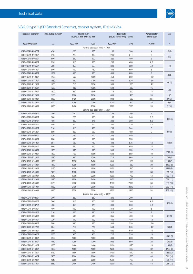
VSI2.0 type 1 (SD Standard Dynamic), cabinet system, IP 21/23/54
Frequency converter Max. output current* Normal duty(120%, 1 min. every 10 min)
Heavy duty (150%, 1 min. every 10 min)
Power loss for normal duty
Size
Type designation Imax PMotor (kW) IN (A) PMotor (kW) IN (A) PV (kW) **
Nominal data apply for U
n = 400 V
VSI2.0CSA1-4/0375A 450 200 375 160 300 4 G (2)
VSI2.0CSA1-4/0430A 516 220 430 200 344 5H (2)
VSI2.0CSA1-4/0500A 600 250 500 220 400 6
VSI2.0CSA1-4/0600A 720 315 600 250 480 6.3
I (3)VSI2.0CSA1-4/0650A 780 355 650 300 520 7.1
VSI2.0CSA1-4/0750A 900 400 750 355 600 8
VSI2.0CSA1-4/0860A 1032 450 860 400 688 9J (4)
VSI2.0CSA1-4/1000A 1200 560 1000 450 800 11.2
VSI2.0CSA1-4/1150A 1380 630 1150 500 920 12.6KA (5)
VSI2.0CSA1-4/1250A 1500 710 1250 560 1000 14.2
VSI2.0CSA1-4/1350A 1620 800 1350 600 1080 16K (6)
VSI2.0CSA1-4/1500A 1800 900 1500 710 1200 18
VSI2.0CSA1-4/1750A 2100 1000 1750 800 1400 20 L (7)
VSI2.0CSA1-4/2000A 2400 1120 2000 900 1600 22.4 M (8)
VSI2.0CSA1-4/2250A 2700 1250 2250 1000 1800 25 N (9)
VSI2.0CSA1-4/2500A 3000 1400 2500 1120 2000 28 O (10)
Nominal data apply for Un = 525 V
VSI2.0CSA1-5/0250A 300 160 250 132 200 4
H69 (2)VSI2.0CSA1-5/0300A 360 220 300 160 240 5.5
VSI2.0CSA1-5/0375A 450 250 375 220 300 6.3
VSI2.0CSA1-5/0400A 480 300 400 250 320 7.5
VSI2.0CSA1-5/0430A 516 315 430 250 344 8
I69 (3)VSI2.0CSA1-5/0500A 600 350 500 300 400 9
VSI2.0CSA1-5/0600A 720 450 600 355 480 11
VSI2.0CSA1-5/0650A 780 450 650 355 520 11
J69 (4)VSI2.0CSA1-5/0720A 864 500 720 400 576 13
VSI2.0CSA1-5/0800A 960 560 800 450 640 14
VSI2.0CSA1-5/0900A 1080 680 900 550 720 17KA69 (5)
VSI2.0CSA1-5/1000A 1200 750 1000 600 800 19
VSI2.0CSA1-5/1200A 1440 900 1200 710 960 23 K69 (6)
VSI2.0CSA1-5/1400A 1680 1050 1400 850 1120 26 L69 (7)
VSI2.0CSA1-5/1600A 1920 1200 1600 1000 1280 30 M69 (8)
VSI2.0CSA1-5/1800A 2160 1400 1800 1100 1440 35 N69 (9)
VSI2.0CSA1-5/2000A 2400 1500 2000 1200 1600 38 O69 (10)
VSI2.0CSA1-5/2200A 2640 1700 2200 1300 1760 43 P69 (11)
VSI2.0CSA1-5/2400A 2880 1800 2400 1450 1920 45 Q69 (12)
VSI2.0CSA1-5/2600A 3120 2000 2600 1600 2080 50 R69 (13)
VSI2.0CSA1-5/2800A 3360 2100 2800 1700 2240 53 S69 (14)
VSI2.0CSA1-5/3000A 3600 2300 3000 1800 2400 58 T69 (15)
Nominal data apply for Un = 690 V
VSI2.0CSA1-6/0250A 300 250 250 200 200 5
H69 (2)VSI2.0CSA1-6/0300A 360 315 300 250 240 6.3
VSI2.0CSA1-6/0375A 450 355 375 300 300 7.1
VSI2.0CSA1-6/0400A 480 400 400 315 320 8
VSI2.0CSA1-6/0430A 516 450 430 315 344 9
I69 (3)VSI2.0CSA1-6/0500A 600 500 500 355 400 10
VSI2.0CSA1-6/0600A 720 600 600 450 480 12
VSI2.0CSA1-6/0650A 780 630 650 500 520 12.6
J69 (4)VSI2.0CSA1-6/0720A 864 710 720 560 576 14.2
VSI2.0CSA1-6/0800A 960 800 800 630 640 16
VSI2.0CSA1-6/0900A 1080 900 900 710 720 18KA69 (5)
VSI2.0CSA1-6/1000A 1200 1000 1000 800 800 20
VSI2.0CSA1-6/1200A 1440 1200 1200 950 960 24 K69 (6)
VSI2.0CSA1-6/1400A 1680 1400 1400 1120 1120 28 L69 (7)
VSI2.0CSA1-6/1600A 1920 1600 1600 1250 1280 32 M69 (8)
VSI2.0CSA1-6/1800A 2160 1800 1800 1400 1440 36 N69 (9)
VSI2.0CSA1-6/2000A 2400 2000 2000 1600 1600 40 O69 (10)
VSI2.0CSA1-6/2200A 2640 2200 2200 1700 1760 44 P69 (11)
VSI2.0CSA1-6/2400A 2880 2400 2400 1900 1920 48 Q69 (12)
Technical data
16
VE
MoD
RIV
E F
requ
ency
Con
vert
er V
SI2
.0 |
VE
MoD
RIV
E S
ingl
e –
Low
vol
tage
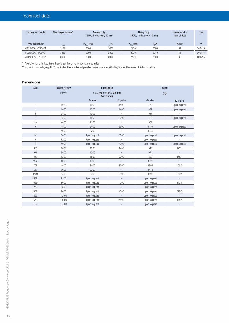
Frequency converter Max. output current* Normal duty(120%, 1 min. every 10 min)
Heavy duty (150%, 1 min. every 10 min)
Power loss for normal duty
Size
Type designation Imax PMotor (kW) IN (A) PMotor (kW) IN (A) PV (kW) **
VSI2.0CSA1-6/2600A 3120 2600 2600 2100 2080 52 R69 (13)
VSI2.0CSA1-6/2800A 3360 2800 2800 2200 2240 56 S69 (14)
VSI2.0CSA1-6/3000A 3600 3000 3000 2400 2400 60 T69 (15)
* Available for a limited time, insofar as the drive temperature permits ** Figure in brackets, e.g. H (2), indicates the number of parallel power modules (PEBBs, Power Electronic Building Blocks)
Dimensions
Size Cooling air flow Dimensions Weight
(m3 / h) H = 2250 mm, D = 600 mmWidth (mm)
(kg)
6-pulse 12-pulse 6-pulse 12-pulse
G 1020 1000 1400 452 Upon request
H 1600 1000 1400 472 Upon request
I 2400 1300 - 617 -
J 3200 1600 2000 790 Upon request
KA 4000 2100 - 931 -
K 4800 2400 2600 1154 Upon request
L 5600 2700 - 1289 -
M 6400 Upon request 3600 Upon request Upon request
N 7200 Upon request - Upon request -
O 8000 Upon request 4200 Upon request Upon request
H69 1600 1000 1400 510 620
I69 2400 1300 - 674 -
J69 3200 1600 2000 820 920
KA69 4000 1900 - 1020 -
K69 4800 2400 2600 1264 1323
L69 5600 2700 - 1472 -
M69 6400 3000 3600 1592 1897
N69 7200 Upon request - Upon request -
O69 8000 Upon request 4200 Upon request 2171
P69 8800 Upon request - Upon request -
Q69 9600 Upon request 4800 Upon request 2788
R69 10400 Upon request - Upon request -
S69 11200 Upon request 5600 Upon request 3187
T69 12000 Upon request - Upon request -
Technical data
17
VE
MoD
RIV
E F
requ
ency
Con
vert
er V
SI2
.0 |
VE
MoD
RIV
E S
ingl
e –
Low
vol
tage
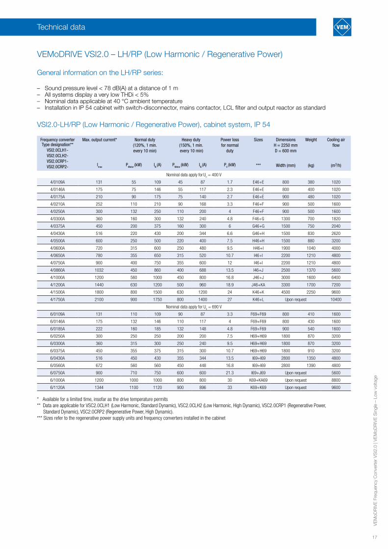
Frequency converter Type designation**
VSI2.0CLH1- VSI2.0CLH2-VSI2.0CRP1- VSI2.0CRP2-
Max. output current* Normal duty(120%, 1 min. every 10 min)
Heavy duty(150%, 1 min. every 10 min)
Power loss for normal
duty
Sizes DimensionsH = 2250 mmD = 600 mm
Weight Cooling air flow
Imax PMotor (kW) IN (A) PMotor (kW) IN (A) PV (kW) *** Width (mm) (kg) (m3/h)
Nominal data apply for U
n = 400 V
4/0109A 131 55 109 45 87 1.7 E46+E 800 380 1020
4/0146A 175 75 146 55 117 2.3 E46+E 800 400 1020
4/0175A 210 90 175 75 140 2.7 E46+E 900 480 1020
4/0210A 252 110 210 90 168 3.3 F46+F 900 500 1600
4/0250A 300 132 250 110 200 4 F46+F 900 500 1600
4/0300A 360 160 300 132 240 4.8 F46+G 1300 700 1820
4/0375A 450 200 375 160 300 6 G46+G 1500 750 2040
4/0430A 516 220 430 200 344 6.6 G46+H 1500 830 2620
4/0500A 600 250 500 220 400 7.5 H46+H 1500 880 3200
4/0600A 720 315 600 250 480 9.5 H46+I 1900 1040 4000
4/0650A 780 355 650 315 520 10.7 I46+I 2200 1210 4800
4/0750A 900 400 750 355 600 12 I46+I 2200 1210 4800
4/0860A 1032 450 860 400 688 13.5 I46+J 2500 1370 5600
4/1000A 1200 560 1000 450 800 16.8 J46+J 3000 1600 6400
4/1200A 1440 630 1200 500 960 18.9 J46+KA 3300 1700 7200
4/1500A 1800 800 1500 630 1200 24 K46+K 4500 2250 9600
4/1750A 2100 900 1750 800 1400 27 K46+L Upon request 10400
Nominal data apply for Un = 690 V
6/0109A 131 110 109 90 87 3.3 F69+F69 800 410 1600
6/0146A 175 132 146 110 117 4 F69+F69 800 430 1600
6/0185A 222 160 185 132 148 4.8 F69+F69 900 540 1600
6/0250A 300 250 250 200 200 7.5 H69+H69 1800 870 3200
6/0300A 360 315 300 250 240 9.5 H69+H69 1800 870 3200
6/0375A 450 355 375 315 300 10.7 H69+H69 1800 910 3200
6/0430A 516 450 430 355 344 13.5 I69+I69 2800 1350 4800
6/0560A 672 560 560 450 448 16.8 I69+I69 2800 1390 4800
6/0750A 900 710 750 600 600 21.3 I69+J69 Upon request 5600
6/1000A 1200 1000 1000 800 800 30 K69+KA69 Upon request 8800
6/1120A 1344 1100 1120 900 896 33 K69+K69 Upon request 9600
* Available for a limited time, insofar as the drive temperature permits** Data are applicable for VSC2.0CLH1 (Low Harmonic, Standard Dynamic), VSC2.0CLH2 (Low Harmonic, High Dynamic), VSC2.0CRP1 (Regenerative Power, Standard Dynamic), VSC2.0CRP2 (Regenerative Power, High Dynamic). *** Sizes refer to the regenerative power supply units and frequency converters installed in the cabinet
Technical data
VSI2.0-LH/RP (Low Harmonic / Regenerative Power), cabinet system, IP 54
General information on the LH/RP series:
– Sound pressure level < 78 dB(A) at a distance of 1 m – All systems display a very low THDi < 5%– Nominal data applicable at 40 °C ambient temperature– Installation in IP 54 cabinet with switch-disconnector, mains contactor, LCL filter and output reactor as standard
VEMoDRIVE VSI2.0 – LH/RP (Low Harmonic / Regenerative Power)
18
VE
MoD
RIV
E F
requ
ency
Con
vert
er V
SI2
.0 |
VE
MoD
RIV
E S
ingl
e –
Low
vol
tage
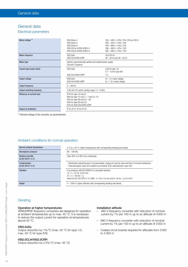
General dataElectrical parameters
Mains voltage ** VSI2.0xSxx-4 VSI2.0xSxx-5VSI2.0xSxx-6VSI2.0CLHx-4/VSI2.0CRPx-4VSI2.0CLHx-6/VSI2.0CRPx-6
230 – 480 V +10%/-15% (10% at 230 V)400 – 525 V +10% /-15%400 – 690 V +10% /-15%380 – 460 V +10% /-15%480 – 690 V +10% /-15%
Mains frequency VSI2.0xSxVSI2.0CLH/VSI2.0CRP
45 to 65 Hz48 – 52 Hz and 58 – 62 Hz
Mains type Earthed, asymmetrically earthed and isolated power supply (TN and IT systems)
Overall input power factor VSI2.0xSx 0.95 for type 1/20.7 – 0.8 for type 8/9
VSI2.0CLH/VSI2.0CRP 1.0
Output voltage VSI2.0xSxVSI2.0CLH/VSI2.0CRP
(0 – 1) x mains voltage(0 – 1.2) x mains voltage
Output frequency 0 – 400 Hz
Output switching frequency 3 kHz (for U/f control; setting range 1.5 – 6 kHz)
Efficiency at nominal load 97% for type 1/2 size B 98% for type 1/2 size C – T and C2 – F293% for type 8/9 size A3 – B395% for type 8/9 size C397% for VSI2.0CLH/VSI2.0CRP
Degree of protection IP 20, IP 21, IP 23, IP 54
Ambient conditions for normal operation
Normal ambient temperature 0 °C to +40 °C; higher temperatures with corresponding derating (see below)
Atmospheric pressure 86 – 106 kPa
Relative humidity(to IEC 60721-3-3)
Class 3K4, 5 to 95% non-condensing
Contamination (to IEC 60721-3-3)
– Electrically conducting dust is not permissible; cooling air must be clean and free of corrosive substances– Chemical gases: class 3C2 (coated circuit boards 3C3); solid particles: class 3S2.
Vibration In accordance with IEC 60068-2-6, sinusoidal vibration: 10 < f < 57 Hz, 0.075 mm 57 < f < 150 Hz, 1 g Sizes B to D2: IEC 60721-3-3 3M4; 2 – 9 Hz, 3.0 mm and 9 – 20 Hz, 1 g (10 m/s2)
Height 0 – 1000 m, higher altitudes with corresponding derating (see below)
** Nominal voltage of the converter, as parameterised
Operation at higher temperatures:VEMoDRIVE frequency converters are designed for operation at ambient temperatures up to max. 40 °C. It is necessary to reduce the output current for operation at temperatures above 40 °C.
VSI2.0xSx:Output reduction by 1%/°C (max. 55 °C for type 1/2, max. 50 °C for type 8/9)
VSI2.0CLH/VSI2.0CRP: Output reduction by 2.5%/°C (max. 45 °C)
Installation altitude– 480 V frequency converter with reduction of nominal
current by 1% per 100 m up to an altitude of 4 000 m
– 690 V frequency converter with reduction of nominal current by 1% per 100 m up to an altitude of 2 000 m
– Coated circuit boards required for altitudes from 2 000 to 4 000 m
General data
Derating

19
VE
MoD
RIV
E F
requ
ency
Con
vert
er V
SI2
.0 |
VE
MoD
RIV
E S
ingl
e –
Low
vol
tage
CE certification All sizes
UL certification / cULus certification All sizes up to and including 1000 A / 480 V and 1500 A / 480 V (type 1/2 only)
Certification for marine sector DNV (type 1/2 only)
EAC All sizes
Product conformity
EMC Directive 2004/108/EG
Low Voltage Directive 2006/95/EG
WEEE Directive 2002/96/EG
Standards and regulations
Europe
EN 60204-1 – Safety of machinery – Electrical equipment of machines, – Part 1: General requirements
EN(IEC)61800-3:2004 – Adjustable-speed electrical power drive systems– Part 3: EMC requirements and specific test methods.– EMC Directive: Declaration of conformity and CE marking
EN(IEC)61800-5-1 Ed. 2.0 – Adjustable speed electrical power drive systems, Part 5-1: Safety requirements - Electrical, thermal and energy
– Low Voltage Directive: Declaration of conformity and CE marking
General applicability
USL – USL (United States Standards listed) in accordance with the stipulations of UL508C – Power conversion equipment
UL 840 – UL safety standard for power conversion equipment: Insulation coordination including clearances and creepage distances for electrical equipment
CNL – CNL (Canadian National Standards listed) in accordance with the stipulations of CAN/CSA C22.2 No. 14-10 – Industrial control equipment
North and South America
EAC (formerly GOST R) For all sizes
Russia
Temperature -20 to +60 °C
Atmospheric pressure 86 to 106 kPa
Relative humidity Class 1K4, max. 95%, non-condensing and no icing
General data
Storage conditions
20
VE
MoD
RIV
E F
requ
ency
Con
vert
er V
SI2
.0 |
VE
MoD
RIV
E S
ingl
e –
Low
vol
tage
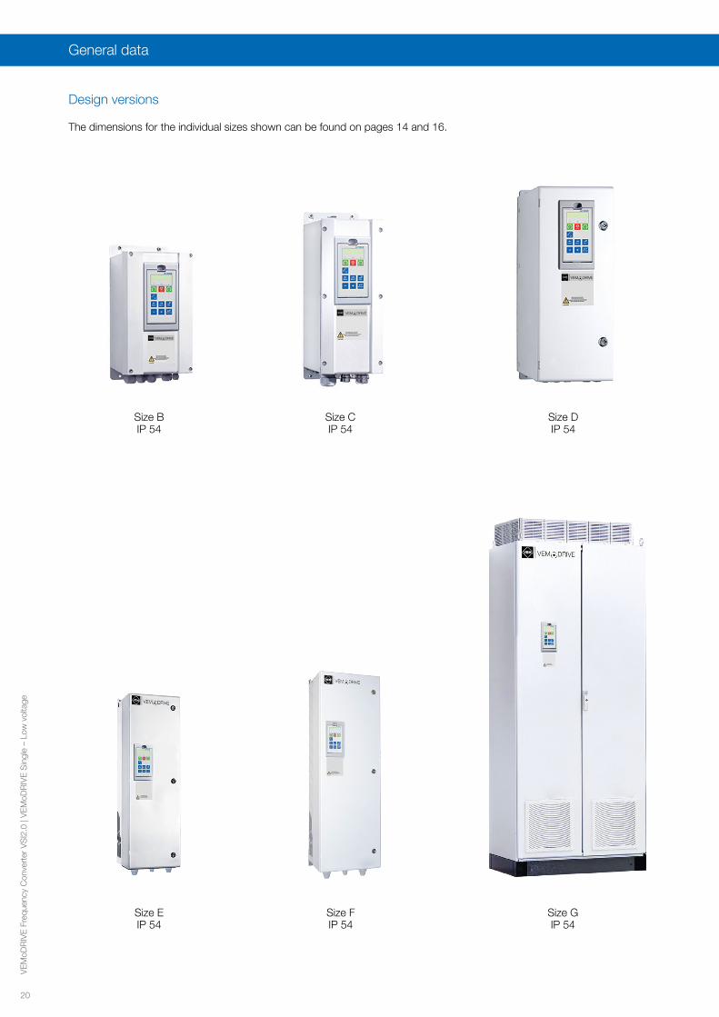
Design versions
Size BIP 54
Size CIP 54
Size DIP 54
Size EIP 54
Size F IP 54
Size GIP 54
General data
The dimensions for the individual sizes shown can be found on pages 14 and 16.
21
VE
MoD
RIV
E F
requ
ency
Con
vert
er V
SI2
.0 |
VE
MoD
RIV
E S
ingl
e –
Low
vol
tage
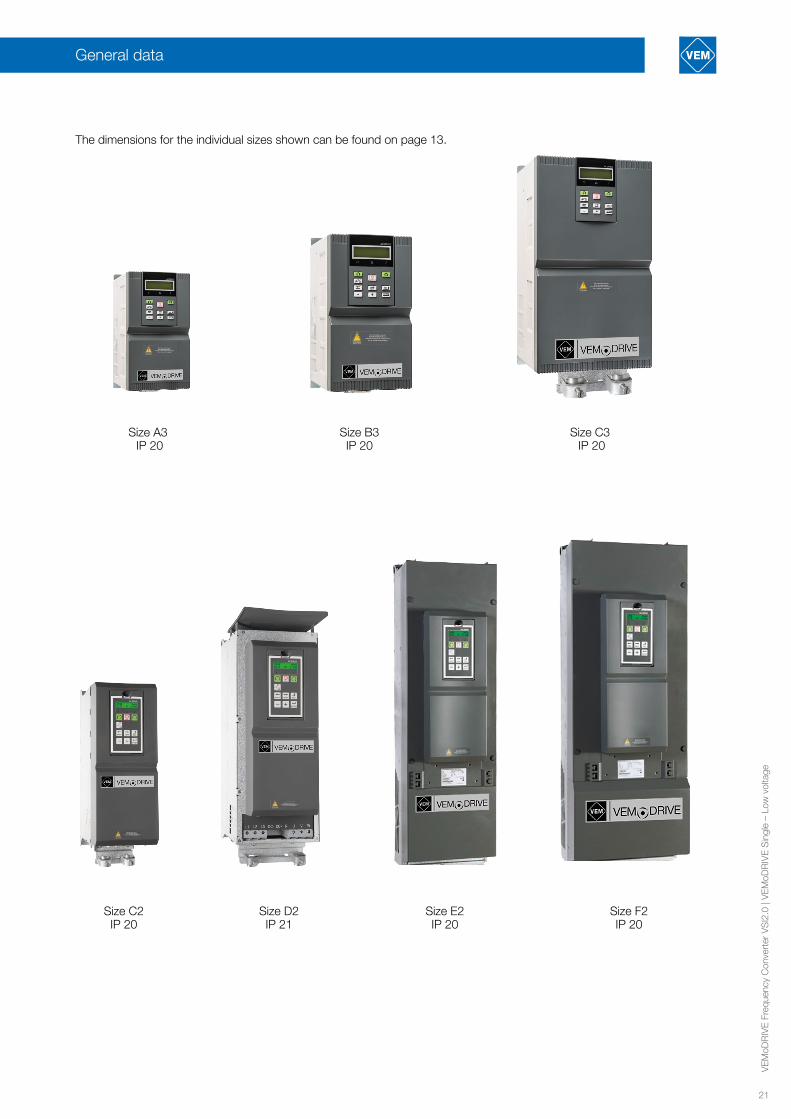
General data
Size C2IP 20
Size D2IP 21
Size F2IP 20
Size E2IP 20
Size A3 IP 20
Size B3 IP 20
Size C3 IP 20
The dimensions for the individual sizes shown can be found on page 13.
22
VE
MoD
RIV
E F
requ
ency
Con
vert
er V
SI2
.0 |
VE
MoD
RIV
E S
ingl
e –
Low
vol
tage
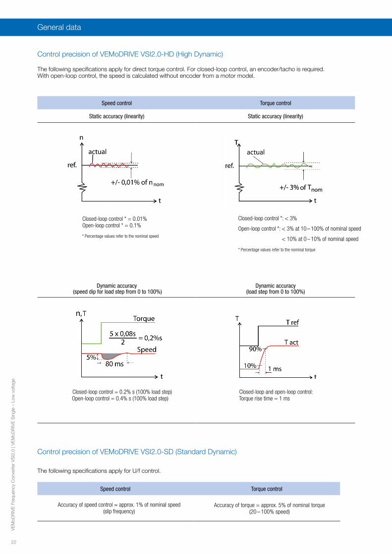
Speed control Torque control
Static accuracy (linearity) Static accuracy (linearity)
Closed-loop control * = 0.01% Open-loop control * = 0.1%
* Percentage values refer to the nominal speed
Dynamic accuracy (speed dip for load step from 0 to 100%)
Dynamic accuracy (load step from 0 to 100%)
Closed-loop control = 0.2% s (100% load step) Open-loop control = 0.4% s (100% load step)
Closed-loop and open-loop control: Torque rise time = 1 ms
Control precision of VEMoDRIVE VSI2.0-HD (High Dynamic)
The following specifications apply for direct torque control. For closed-loop control, an encoder/tacho is required. With open-loop control, the speed is calculated without encoder from a motor model.
Speed control Torque control
Accuracy of speed control = approx. 1% of nominal speed(slip frequency)
Accuracy of torque = approx. 5% of nominal torque (20 – 100% speed)
Control precision of VEMoDRIVE VSI2.0-SD (Standard Dynamic)
The following specifications apply for U/f control.
General data
Closed-loop control *: < 3%
Open-loop control *: < 3% at 10 – 100% of nominal speed
< 10% at 0 – 10% of nominal speed
* Percentage values refer to the nominal torque

23
VE
MoD
RIV
E F
requ
ency
Con
vert
er V
SI2
.0 |
VE
MoD
RIV
E S
ingl
e –
Low
vol
tage
Speed control Torque control
Static accuracy (linearity) Static accuracy (linearity)
Closed-loop control * = 0.01% Open-loop control * = 0.1%
* Percentage values refer to the nominal speed
Dynamic accuracy (speed dip for load step from 0 to 100%)
Dynamic accuracy (load step from 0 to 100%)
Closed-loop control = 0.2% s (100% load step) Open-loop control = 0.4% s (100% load step)
Closed-loop and open-loop control: Torque rise time = 1 ms
InterfacesOverview
Interfaces
X1 Name Function (default setting)
1 +10 V +10 V DC supply voltage
2 AnIn1 Set speed
3 AnIn2 Not used
4 AnIn3 Not used
5 AnIn4 Not used
6 -10 V -10 V DC supply voltage
7 Common Signal earth
8 DigIn 1 RunL
9 DigIn 2 RunR
10 DigIn 3 Not used
11 +24 V +24 V DC supply voltage
12 Common Signal earth
13 AnOut 1 Min. speed to max. speed
14 AnOut 2 0 to max. torque
15 Common Signal earth
16 DigIn 4 Not used
17 DigIn 5 Not used
18 DigIn 6 Not used
19 DigIn 7 Not used
X1 Name Function (default setting)
20 DigOut 1 Ready
21 DigOut 2 Brake/no error
22 DigIn 8 Reset
X2 Name Function (default setting)
31 N/C 1 Relay 1 output = ErrorEnergised when the frequency converter is in ERROR state.N/C is opened when the relay is energised (applies for all relays) N/O is closed when the relay is energised (applies for all relays)
32 COM 1
33 N/O 1
41 N/C 2Relay 2 output = ReadyEnergised when the converter is ready to start
42 COM 2
43 N/O 2
X3 Name Function (default setting)
51 COM 3Relay 3 output = Not used
52 N/O 3
Type 8/9 Type 1/2
EMC Filter
** DC link reactor** Brake resistor
* = Standard presetting ** = Optionally
* = Standard presetting *** = Option terminals X1; 78-79 to connect the motor
PTC option to sizes B up be D2
Relay
Relay
Relay
Relay
Relay
Relay
Error
Ready
Error
Ready
Optionally***Optionally
Options OptionsComm.
Field bus Option or
PC
Option Circuit board
Options OptionsComm.
Field bus Option or
PC
Option Circuit board
Further
EMC Filter
All inputs and outputs are programmable.
24
VE
MoD
RIV
E F
requ
ency
Con
vert
er V
SI2
.0 |
VE
MoD
RIV
E S
ingl
e –
Low
vol
tage
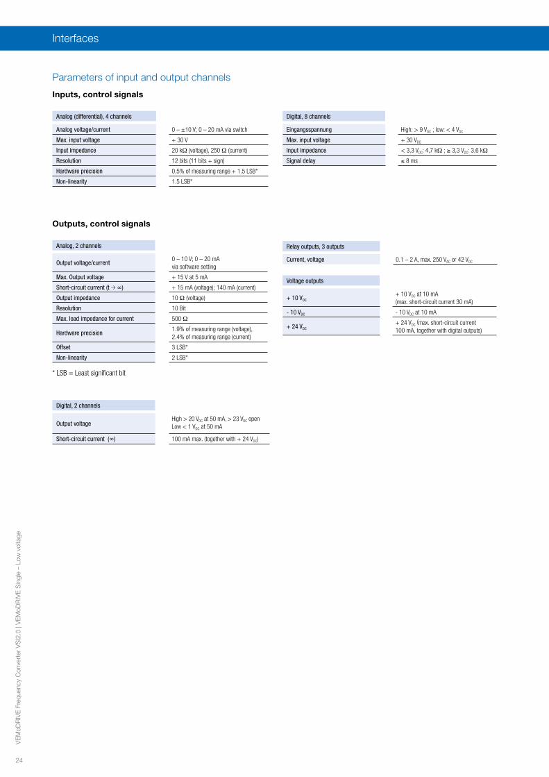
Parameters of input and output channels
Analog (differential), 4 channels
Analog voltage/current 0 – ±10 V; 0 – 20 mA via switch
Max. input voltage + 30 V
Input impedance 20 kΩ (voltage), 250 Ω (current)
Resolution 12 bits (11 bits + sign)
Hardware precision 0.5% of measuring range + 1.5 LSB*
Non-linearity 1.5 LSB*
Inputs, control signals
Digital, 8 channels
Eingangsspannung High: > 9 VDC ; low: < 4 VDC
Max. input voltage + 30 VDC
Input impedance < 3,3 VDC: 4,7 kΩ ; ≥ 3,3 VDC: 3,6 kΩ
Signal delay ≤ 8 ms
Analog, 2 channels
Output voltage/current0 – 10 V; 0 – 20 mA via software setting
Max. Output voltage + 15 V at 5 mA
Short-circuit current (t → ∞) + 15 mA (voltage); 140 mA (current)
Output impedance 10 Ω (voltage)
Resolution 10 Bit
Max. load impedance for current 500 Ω
Hardware precision1.9% of measuring range (voltage), 2.4% of measuring range (current)
Offset 3 LSB*
Non-linearity 2 LSB*
Outputs, control signals
Digital, 2 channels
Output voltageHigh > 20 VDC at 50 mA, > 23 VDC openLow < 1 VDC at 50 mA
Short-circuit current (∞) 100 mA max. (together with + 24 VDC)
Relay outputs, 3 outputs
Current, voltage 0.1 – 2 A, max. 250 VAC or 42 VDC
Voltage outputs
+ 10 VDC+ 10 VDC at 10 mA (max. short-circuit current 30 mA)
- 10 VDC - 10 VDC at 10 mA
+ 24 VDC+ 24 VDC
(max. short-circuit current 100 mA, together with digital outputs)
* LSB = Least significant bit
Interfaces

25
VE
MoD
RIV
E F
requ
ency
Con
vert
er V
SI2
.0 |
VE
MoD
RIV
E S
ingl
e –
Low
vol
tage
Options for the frequency converter VSI2.0Overview
Option Type 8/9 Type 1/2
No. of possible option boards max. 2 function boards + 1 communication board max. 3 function boards + 1 communication board
Coated circuit boards StandardStandard for sizes C2 – F2Optional for all other sizes
Function boards
I / O-Board X X (also several possible)
Encoder-Board X X
PTC/PT100-Board - X
PTC input XX* (no board slot occupied, optional for sizes B – D, standard for
C2 – F2)
CRIO board - X (for HD High Dynamic only)
Standby-Spannungsversorgung X X*
STO X X* (no board slot occupied for size E/E2 and larger)
Communication boards
Profibus DP X X
DeviceNet X X
Modbus TCP X X
Modbus TCP M12 X X
RS232/485 (Modbus RTU) X X
EtherCAT® X X
Profinet IO 1-Port X X
Profinet IO 2-Port X X
Ethernet IP 2-Port X X
Filters
EMC filter, category C2 - X*
Output reactor X X (standard for 690 V, for VSI2.0CLH and VSI2.0CRP)
Overvoltage feedback X X (standard for 690 V)
Sine-wave filter X (type 8 only) X (type 1 only)
Common mode filter X X
Control panels
Control panel for cabinet door - X (standard for cabinet systems)
Hand-held control panel HCP 2.0 - X
VEMoSoftCom + USB/RS232-Kit X X
Further options
EMV-glands - X (sizes B – D)
Brake chopper Standard X*
Connection DC +/- Standard X* (standard for 690 V)
Crane interface - X (for HD: 230 VAC or 24 VAC)
Braking resistors X X
Liquid cooling - X (from IN ≥ 90 A)
Link reactor X Standard
Circuit-breaker instead of switch disconnector - X* (for all cabinet systems)
12-pulse version -X* (for cabinet systems with even number of PEBBs,
incl. circuit-breaker)
X = Option available; please specify when ordering* These options are factory-installed
Options for the frequency converter VSI2.0

26
VE
MoD
RIV
E F
requ
ency
Con
vert
er V
SI2
.0 |
VE
MoD
RIV
E S
ingl
e –
Low
vol
tage
Coated circuit boards – All boards can be supplied in coated versions. Recommended for applications subject to difficult climatic conditions, such as tropical, salty or very dusty environments, high humidity and altitudes over 2000 m. (IEC 60721-3-3, gas class 3C3, solid particles 3S2)
I/O-Board – 3 additional relay outputs (230 VAC
, 5 A, NO/NC: Normally Open/Closed). Ideal for the control of several pump or fan drives.– 3 additional differential digital inputs (24 V; 3.2 kΩ; AC/DC), programmable. Inputs provide for insulation of 50 V (AC/DC)
between the channels.– Max. 3 I/O boards can be installed per frequency converter.
Encoder-Board – Input suitable for 5V- (TTL) or 24V- (HTL) incremental encoder.– Resolution: 5 to 16,384 pulses/revolution (min. 9 kΩ, max. frequency = 100 kHz) – For single-ended (A/B) and differential encoders (A/B, A’/B’)– Selectable encoder supply voltage 5 V
DC or 24 V
DC.
PTC/PT100-Board – 1 isolated PTC input (in accordance with DIN 44081/44082): max. 6 PTC thermistors can be connected in series – 3 PT100 inputs for 2/3/4-conductor cables (in accordance with EN 60751)
PTC input – 1 isolated PTC input (in accordance with DIN 44081/44082): max. 6 PTC thermistors can be connected in series – Select the PTC/PT100 option if additional inputs are required.
CRIO board (High Dynamic) – Crane option board to control hoist or travel motions. – Inputs for joystick control supporting 4-step, motor potentiometer or analog reference joystick types.– Inputs for slow down and end limit switches.– All 12 digital inputs 24 V
DC (5 kΩ , 8 – 24 V
DC).
– 2 relay outputs 250 VAC
(2 A) for protection of the mechanical brake and for protection in case of load deviations. – Enables high lifting speeds by making use of field weakening.
Standby power supply – Connection to an external 24 V (AC / DC) power supply to maintain a supply to the control (control board, control panel, commu-nication) in case of main supply shutdown.
STO (Safe Torque Off)
– The additionally integrated inputs and outputs for the auxiliary circuits (STO) comply with the standards EN-IEC 62061:2005 SIL3 and EN-ISO 13849-1:2006. With this option, it is possible to realise stop category 0 in SIL3 or PL e; stop categories 1 and 2 can be realised in conjunction with an additional safety relay.
Function boards
Profibus DP – Field bus option module for Profibus DP or DP V1 communication; 9-pin D-sub connector. – Baud rates: 9.6 kbits/s to 12 Mbits/s
DeviceNet – Field bus option module for DeviceNet communication. – Baud rates: 125 – 500 kbit/s
Modbus/TCP – Industrial Ethernet option module for the Modbus/TCP protocol; RJ45 connector. – Baud rates: 125 to 500 kbits/s
Modbus/TCP M12 – Industrial Ethernet option module for the Modbus/TCP protocol; M12 connector. – Baud rates: 10 or 100 Mbits/s
RS232/RS485 (Modbus RTU) – Isolated RS232/RS485 serial communication board for the Modbus/RTU communication protocol. – Baud rates: 2400 to 38400 bits/s.
Profinet IO 1-Port – Industrial Ethernet option module for the Profinet IO (RT) protocol; RJ45 connector. – Baud rate: 100 Mbits/s
Profinet IO 2-Port – Industrial Ethernet option module for the Profinet IO (RT) protocol; 2 x RJ45 connector. – Baud rate: 100 Mbits/s
EtherCAT® – Industrial Ethernet option module for the EtherCAT protocol– 2 x RJ45 connector (IN and OUT).– Baud rate: 100 Mbits/s
EtherNet IP 2-Port – Industrial Ethernet option module for the Ethernet IP protocol; 1 x RJ45 connector. – Baud rate: 100 Mbits/s
Communication boards: Field bus and Ethernet
Typical frequency converter response time = 10 ms (excluding possible Ethernet delays).
Options for the frequency converter VSI2.0

27
VE
MoD
RIV
E F
requ
ency
Con
vert
er V
SI2
.0 |
VE
MoD
RIV
E S
ingl
e –
Low
vol
tage
Options for the frequency converter VSI2.0
Filters
Phenomenon Common mode filters Output reactors Output reactors and overvoltage
feedback Sine-wave filter
All-pole sine-wave filter
Common mode currents Effective Limited effectiveness Limited effectiveness Effective Very effective
Bearing currents Effective - - - Very effective
Voltage peaks U-V-W - Limited effectiveness Very effective Very effective Very effective
Voltage peaks U-PE - Limited effectiveness Effective Limited effectiveness Very effective
dU/dt - Effective Effective Very effective Very effective
Minimisation of motor noise - Limited effectiveness Limited effectiveness Effective Effective
EMC: Conducted emissions Limited effectiveness Limited effectiveness Limited effectiveness Effective Very effective
Selection matrix
Situation Common mode filters Output reactors Output reactors and overvoltage
feedbackSine-wave filter
All-pole sine-wave filter
Unrated, sensitive or unfavourably positioned motors
X - - X -
Motor in size > 280 X - - - -
IEC 60034-17 motor - X - - -
IEC 60034-25 curve A motor
Cable lengths** 100 – 200 m - X - - -
Cable lengths** 200 – 500 m - - - - X
Dynamic use with frequently raised DC voltage (braking)
- - X - -
Cable without shielding * - - - - X
Recommendations for different mains voltages up to and including 480 V
Situation Common mode filters Output reactors Output reactors and overvoltage
feedbackSine-wave filter
All-pole sine-wave filter
Unrated, sensitive or unfavourably positioned motors
X - - X -
Motor in size > 280 X - - - -
3 kV insulation windings
IEC 60034-25 curve A motor
Cable lengths** 100 – 200 m - - X - -
Cable lengths** 200 – 500 m - - - X -
Dynamic utilisation with frequently increased DC voltage (braking)
- - X - -
Cable without shielding* - - - - X
Recommendations for different mains voltages from 500 to 690 V
X = Recommended solution for this installation configuration* Conducted interference limits for motors without shielding – Cables in accordance with EN 61800-3, Table 16 ** No precautionary measures are necessary for cable lengths up to 100 m.
RemarksThe tables are based on EMC-compliant cabling with shielded cables and proper EMC installation. The voltage drop in the complete system must not
exceed 10% of the supply voltage.Sine-wave filters are only used in conjunction with VSI2.0-SD (Standard Dynamic).

28
VE
MoD
RIV
E F
requ
ency
Con
vert
er V
SI2
.0 |
VE
MoD
RIV
E S
ingl
e –
Low
vol
tage
Options for the frequency converter VSI2.0
Enhanced EMC category C2 Note: EMC filters conforming to the specifications for category C3 (second environment) are integrated on the input side of all VSI2.0 converters as standard. EMC filters in accordance with EN 61800-3:2004 category C2 (first environment) are available as options.
Technical data:– Factory-mounted internal module for sizes B to D2 – Separate module from size E (90 – 700 A); selection
according to the table below– Nominal voltage UN = 480 V, 50/60 Hz – IP 20 = Screw terminal (protected) – IP 00 = Busbar terminals– Max. 40 °C ambient temperature
Type designation Converter nominal current (A) Dimensions H x W x D (mm)
Weight (kg) Degree of protection
3F480-100.230 90 – 100 325 x 150 x 107 7.1 IP 20
3F480-125.230 100 – 125 345 x 175 x 127 10 IP 203F480-150.230 125 – 150 375 x 175 x 135 10 IP 203F480-180.230 150 – 180 490 x 170 x 158 13.5 IP 003F480-220.230 180 – 220 490 x 170 x 158 13.5 IP 003F480-250.230 220 – 250 490 x 230 x 158 18.2 IP 003F480300.230 250 – 300 490 x 230 x 158 18.2 IP 003F480-400.230 300 – 400 580 x 230 x 158 22 IP 003F480-500.230 400 – 500 630 x 345 x 158 37.5 IP 003F480-600.230 500 – 600 660 x 375 x 187 42 IP 003F480-700.230 600 – 700 865 x 345 x 157 42 IP 00
Output reactorsThe incorporation of output reactors is recommended for cable lengths from 100 metres and for 690 V systems. The switching of the output voltage results in voltage peaks in the motor windings (up to twice the DC link voltage with a rate of voltage rise du/dt of up to 5 kV/μs) due to parasitic capacitances in the cables. Such peaks can damage the motor insulation. With shielded cables, the parasitic capa-citances are even higher. Output reactors serving to reduce the voltage peaks must be installed as close as possible to the converter output. The rate of voltage rise du/dt at the motor terminals is reduced to less than 500 V/μs.
Output reactors can be installed in parallel arrangements where higher currents are necessary, e.g. one reactor each per PEBB (Power Electronic Building Block).
Please feel free to contact us for further information.
Our 690 V cabinet system converters (VSI2.0CSxx-6) are provided with appropriate output reactors and overvoltage feedback as standard.
Technical data:– Nominal voltage UN = 800 V– IP 00– Suitable for cabinet installation – Max. 40 °C ambient temperature
Type designation Nominal current IN (A) L (mH) Weight (kg) Dimensions H x W x D (mm)
02A8 2.8 1.5 0.6 60 x 78 x 95
04A4 4.4 1 0.6 60 x 78 x 9506A6 6.6 0.65 0.6 60 x 78 x 95011A 11 0.4 1 65 x 96 x 105014A 14.3 0.3 1 65 x 96 x 105018A 18.2 0.25 1.2 74 x 96 x 105026A 26.4 0.175 1.2 74 x 96 x 105032A 32 0.15 1.7 84 x 125 x 140065A 65 0.1 4 105 x 155 x 205090A 90 0.1 8.4 120 x 90 x 235146A 146 0.05 10.2 140 x 190 x 260175A 175 0.05 13.4 160 x 210 x 180275A 275 0.032 18.4 170 x 230 x 200320A 320 0.025 18.9 170 x 230 x 200410A 410 0.021 22.6 180 x 240 x 210
Overvoltage feedbackIn combination with an output reactor, the overvoltage feedback limits the voltage at the motor terminals such that it does not exceed the DC link voltage + 100 V. This option is available for nominal voltages from 380 to 690 V and requires the option “Connection DC +/-”. The module dimensions are H x W x D = 250 x 145 x 95 mm. Our 690 V cabinet system converters (VSI2.0CSxx-6) are provided with appropriate output reactors and overvoltage feedback as standard.
29
VE
MoD
RIV
E F
requ
ency
Con
vert
er V
SI2
.0 |
VE
MoD
RIV
E S
ingl
e –
Low
vol
tage
Options for the frequency converter VSI2.0
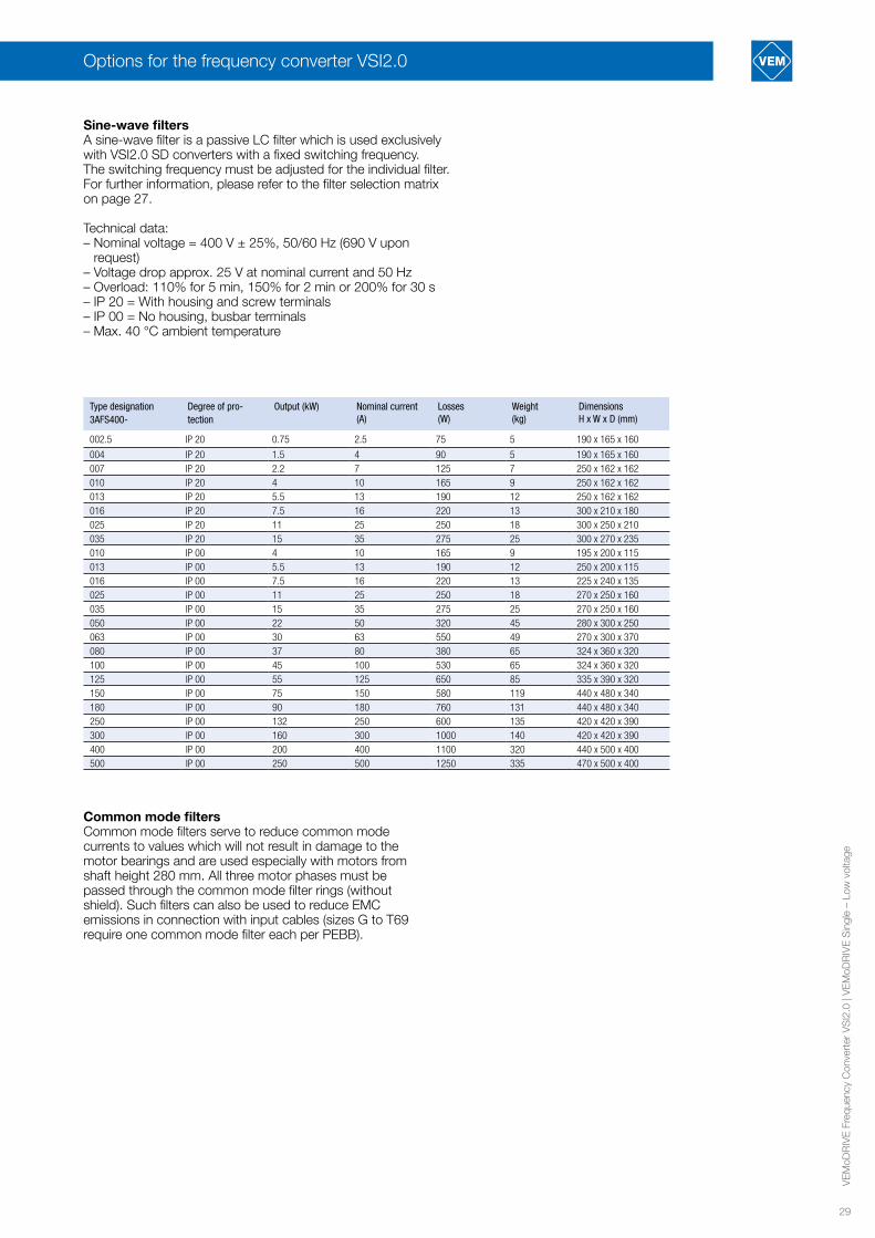
Sine-wave filtersA sine-wave filter is a passive LC filter which is used exclusively with VSI2.0 SD converters with a fixed switching frequency. The switching frequency must be adjusted for the individual filter. For further information, please refer to the filter selection matrix on page 27.
Technical data:– Nominal voltage = 400 V ± 25%, 50/60 Hz (690 V upon
request) – Voltage drop approx. 25 V at nominal current and 50 Hz– Overload: 110% for 5 min, 150% for 2 min or 200% for 30 s– IP 20 = With housing and screw terminals– IP 00 = No housing, busbar terminals – Max. 40 °C ambient temperature
Type designation3AFS400-
Degree of pro-tection
Output (kW) Nominal current (A)
Losses(W)
Weight(kg)
DimensionsH x W x D (mm)
002.5 IP 20 0.75 2.5 75 5 190 x 165 x 160
004 IP 20 1.5 4 90 5 190 x 165 x 160007 IP 20 2.2 7 125 7 250 x 162 x 162010 IP 20 4 10 165 9 250 x 162 x 162013 IP 20 5.5 13 190 12 250 x 162 x 162016 IP 20 7.5 16 220 13 300 x 210 x 180025 IP 20 11 25 250 18 300 x 250 x 210035 IP 20 15 35 275 25 300 x 270 x 235010 IP 00 4 10 165 9 195 x 200 x 115013 IP 00 5.5 13 190 12 250 x 200 x 115016 IP 00 7.5 16 220 13 225 x 240 x 135025 IP 00 11 25 250 18 270 x 250 x 160035 IP 00 15 35 275 25 270 x 250 x 160050 IP 00 22 50 320 45 280 x 300 x 250063 IP 00 30 63 550 49 270 x 300 x 370080 IP 00 37 80 380 65 324 x 360 x 320100 IP 00 45 100 530 65 324 x 360 x 320125 IP 00 55 125 650 85 335 x 390 x 320150 IP 00 75 150 580 119 440 x 480 x 340180 IP 00 90 180 760 131 440 x 480 x 340250 IP 00 132 250 600 135 420 x 420 x 390300 IP 00 160 300 1000 140 420 x 420 x 390400 IP 00 200 400 1100 320 440 x 500 x 400500 IP 00 250 500 1250 335 470 x 500 x 400
Common mode filtersCommon mode filters serve to reduce common mode currents to values which will not result in damage to the motor bearings and are used especially with motors from shaft height 280 mm. All three motor phases must be passed through the common mode filter rings (without shield). Such filters can also be used to reduce EMC emissions in connection with input cables (sizes G to T69 require one common mode filter each per PEBB).
30
VE
MoD
RIV
E F
requ
ency
Con
vert
er V
SI2
.0 |
VE
MoD
RIV
E S
ingl
e –
Low
vol
tage
Options for the frequency converter VSI2.0
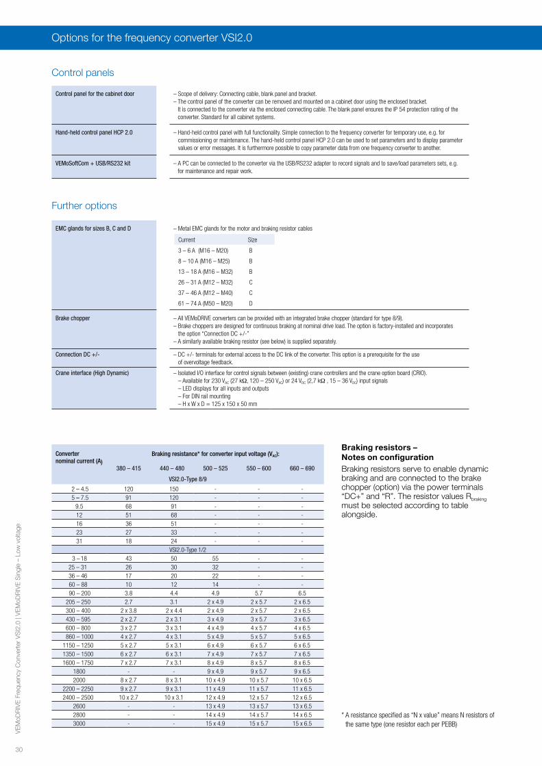
Control panel for the cabinet door – Scope of delivery: Connecting cable, blank panel and bracket.– The control panel of the converter can be removed and mounted on a cabinet door using the enclosed bracket.
It is connected to the converter via the enclosed connecting cable. The blank panel ensures the IP 54 protection rating of the converter. Standard for all cabinet systems.
Hand-held control panel HCP 2.0 – Hand-held control panel with full functionality. Simple connection to the frequency converter for temporary use, e.g. for commissioning or maintenance. The hand-held control panel HCP 2.0 can be used to set parameters and to display parameter values or error messages. It is furthermore possible to copy parameter data from one frequency converter to another.
VEMoSoftCom + USB/RS232 kit – A PC can be connected to the converter via the USB/RS232 adapter to record signals and to save/load parameters sets, e.g. for maintenance and repair work.
Control panels
EMC glands for sizes B, C and D – Metal EMC glands for the motor and braking resistor cables
Brake chopper – All VEMoDRIVE converters can be provided with an integrated brake chopper (standard for type 8/9).– Brake choppers are designed for continuous braking at nominal drive load. The option is factory-installed and incorporates
the option “Connection DC +/-”– A similarly available braking resistor (see below) is supplied separately.
Connection DC +/- – DC +/- terminals for external access to the DC link of the converter. This option is a prerequisite for the use of overvoltage feedback.
Crane interface (High Dynamic) – Isolated I/O interface for control signals between (existing) crane controllers and the crane option board (CRIO).– Available for 230 VAC (27 kΩ, 120 – 250 VAC) or 24 VDC (2,7 kΩ , 15 – 36 VDC) input signals– LED displays for all inputs and outputs– For DIN rail mounting – H x W x D = 125 x 150 x 50 mm
Further options
Converter nominal current (A)
Braking resistance* for converter input voltage (VAC):
380 – 415 440 – 480 500 – 525 550 – 600 660 – 690
VSI2.0-Type 8/9
2 – 4.5 120 150 - - - 5 – 7.5 91 120 - - -
9.5 68 91 - - -12 51 68 - - -16 36 51 - - -23 27 33 - - -31 18 24 - - -
VSI2.0-Type 1/2 3 – 18 43 50 55 - -
25 – 31 26 30 32 - - 36 – 46 17 20 22 - - 60 – 88 10 12 14 - -
90 – 200 3.8 4.4 4.9 5.7 6.5 205 – 250 2.7 3.1 2 x 4.9 2 x 5.7 2 x 6.5 300 – 400 2 x 3.8 2 x 4.4 2 x 4.9 2 x 5.7 2 x 6.5 430 – 595 2 x 2.7 2 x 3.1 3 x 4.9 3 x 5.7 3 x 6.5 600 – 800 3 x 2.7 3 x 3.1 4 x 4.9 4 x 5.7 4 x 6.5
860 – 1000 4 x 2.7 4 x 3.1 5 x 4.9 5 x 5.7 5 x 6.5 1150 – 1250 5 x 2.7 5 x 3.1 6 x 4.9 6 x 5.7 6 x 6.5 1350 – 1500 6 x 2.7 6 x 3.1 7 x 4.9 7 x 5.7 7 x 6.5 1600 – 1750 7 x 2.7 7 x 3.1 8 x 4.9 8 x 5.7 8 x 6.5
1800 - - 9 x 4.9 9 x 5.7 9 x 6.52000 8 x 2.7 8 x 3.1 10 x 4.9 10 x 5.7 10 x 6.5
2200 – 2250 9 x 2.7 9 x 3.1 11 x 4.9 11 x 5.7 11 x 6.5 2400 – 2500 10 x 2.7 10 x 3.1 12 x 4.9 12 x 5.7 12 x 6.5
2600 - - 13 x 4.9 13 x 5.7 13 x 6.52800 - - 14 x 4.9 14 x 5.7 14 x 6.53000 - - 15 x 4.9 15 x 5.7 15 x 6.5
* A resistance specified as “N x value” means N resistors of the same type (one resistor each per PEBB)
Braking resistors –Notes on configurationBraking resistors serve to enable dynamic braking and are connected to the brake chopper (option) via the power terminals “DC+” and “R”. The resistor values Rbraking must be selected according to table alongside.
Current Size
3 – 6 A (M16 – M20) B
8 – 10 A (M16 – M25) B
13 – 18 A (M16 – M32) B
26 – 31 A (M12 – M32) C
37 – 46 A (M12 – M40) C
61 – 74 A (M50 – M20) D

31
VE
MoD
RIV
E F
requ
ency
Con
vert
er V
SI2
.0 |
VE
MoD
RIV
E S
ingl
e –
Low
vol
tage
Options for the frequency converter VSI2.0
The maximum possible braking power Pbraking,max is dependent on the braking voltage level Ubraking of the converter link:
Converter input voltage (VAC) Braking link voltage Ubraking (VDC)
220 – 240 380380 – 415 660440 – 480 780500 – 525 860550 – 600 1000660 – 690 1150
The maximum possible braking power Pbraking,max can then be calculated in accordance with the number of resistors N with:
Pbraking,max = N . (Ubraking
)2
Rbraking
The dimensions of the resistor can be determined from the table below on the basis of the actually required braking power Pbraking and the duty cycle (ED), where
ED = tbraking
120 s
A duty cycle of ED = 1 is always assumed for braking durations exceeding 120 s.
Type designation Braking power Pbraking (kW) according to duty cycle (ED) Dimensions H x W x D (mm)
100% 60% 40% 25% 6% IP 54
VPR 200-__R 0.2 0.32 0.47 0.74 3.6 200 x 60 x 31
VPR 300-__R 0.3 0.48 0.71 1.11 5.4 250 x 60 x 31VPR 400-__R 0.4 0.63 0.94 1.48 7.2 301 x 60 x 31VPR 500-__R 0.5 0.80 1.18 1.85 9.0 370 x 60 x 31DEGT1VPR1000S_R-S 1 1.40 2.00 3.70 13.0 542 x 98 x 170
IP 20 IP 23BEGT 13#05-__R 2.5 3.25 4.25 6.25 21.0 301 x 483 x 326 500 x 483 x 326BEGT 13#08-__R 4.0 5.2 6.8 10.0 34.0 301 x 483 x 326 500 x 483 x 326BEGT 13#10-_R_ 5.0 6.5 8.5 12.5 42.5 301 x 483 x 326 500 x 483 x 326BEGT 14#15-_R_ 7.5 9.8 12.7 18.7 64 301 x 483 x 426 500 x 483 x 426BEGT 15#20-_R_ 10 13.0 17.0 25.0 85 500 x 483 x 526 301 x 483 x 526BEGT 17#30-_R_ 15 19.5 25.5 37.5 127 301 x 483 x 740 500 x 483 x 740BEGT 25#40-_R_ 20 26 34 50 170 601 x 484 x 526 800 x 484 x 526BEGT 27#60-_R_ 30 39 51 75 255 601 x 484 x 736 800 x 484 x 736BEGT 37#90-_R_ 40 52 68 100 340 1021 x 484 x 736 1181 x 484 x 736BEGT 47#120-_R_ 50 65 85 125 425 1321 x 483 x 736 301 x 483 x 7362xBEGT 27#60-_R_ 60 78 102 150 510 2x (601 x 484 x 736) 2x (800 x 484 x 736)2xBEGT 37#78-_R_ 70 91 119 175 600 2x (1021 x 484 x 736) 2x (1181 x 484 x 736)2xBEGT 37#90-_R_ 80 104 136 200 680 2x (1021 x 484 x 736) 2x (1181 x 484 x 736)2xBEGT 47#120-_R_ 100 130 170 250 850 2x (1321 x 483 x 736) 2x (1481 x 483 x 736)
When ordering braking resistors, please specify the nominal output, the resistance value and the degree of protection:
# = 2 for IP 20 (e.g. BEGT 13205) / # = 4 for IP 23, (e.g. BEGT 13405)__R: Resistance in ohms; example: 26R = 26 ohms_R_: Resistance in ohms; example 6R5 = 6.5 ohms
Liquid coolingFrequency converter for IN ≥ 90 A in sizes E – O and F69 – T69 can also be supplied with liquid cooling. The recooling is realised via a heat exchanger (water-water or water-air) which is not included in the scope of delivery. Connection is by way of rubber hoses with leak-proof quick couplings.
DC link reactors A DC link reactor reduces the THDi of the input current to approx. 30 – 40% and raises the input power factor of the converter to 0.95. A reactor is integrated as standard for types 1/2. For types 8/9, an optional reactor can be supplied in the form of a line reactor.
Circuit-breaker instead of switch-disconnectorFor cabinet systems in the 6-pulse version, the standard switch-disconnector can also be replaced with a circuit-breaker with protective function.
12-pulse version To reduce mains pollution, it is possible to select a 12-pulse version for converters from size G. Converters with a 12 pulse input rectifier are connected by way of a three-winding transformer, which makes two three-phase systems with an electrical offset of 30° available on the secondary side. The mains-side THDi is reduced from 30 – 40% (6 pulse) to 10 – 12%. A further reduction to ≤5% can be achieved with our Low Harmonic converter series VSI2.0CLH.
12-pulse versions can only be supplied for even numbers of PEBBs (sizes G (2), H (4) and so on). Converters in 12 pulse versions are always designed with motor-operated circuit-breakers.
VEM GmbHPirnaer Landstraße 17601257 DresdenGermany
VEM SalesLow voltage departmentFon +49 3943 68-3127Fax +49 3943 68-2440E-Mail: [email protected]
High voltage departmentFon +49 351 208-3237Fax +49 351 208-1108E-Mail: [email protected]
Drive systems departmentFon +49 351 208-1154Fax +49 351 208-1185E-Mail: [email protected]
VEM ServiceFon +49 351 208-3237Fax +49 351 208-1108E-Mail: [email protected]
www.vem-group.com
© 2017 Juniks Marketing GmbH
VEM-NS-2017-12
Printed in Germany. Subject to change.
Cover photo: