catia book
TRANSCRIPT
1
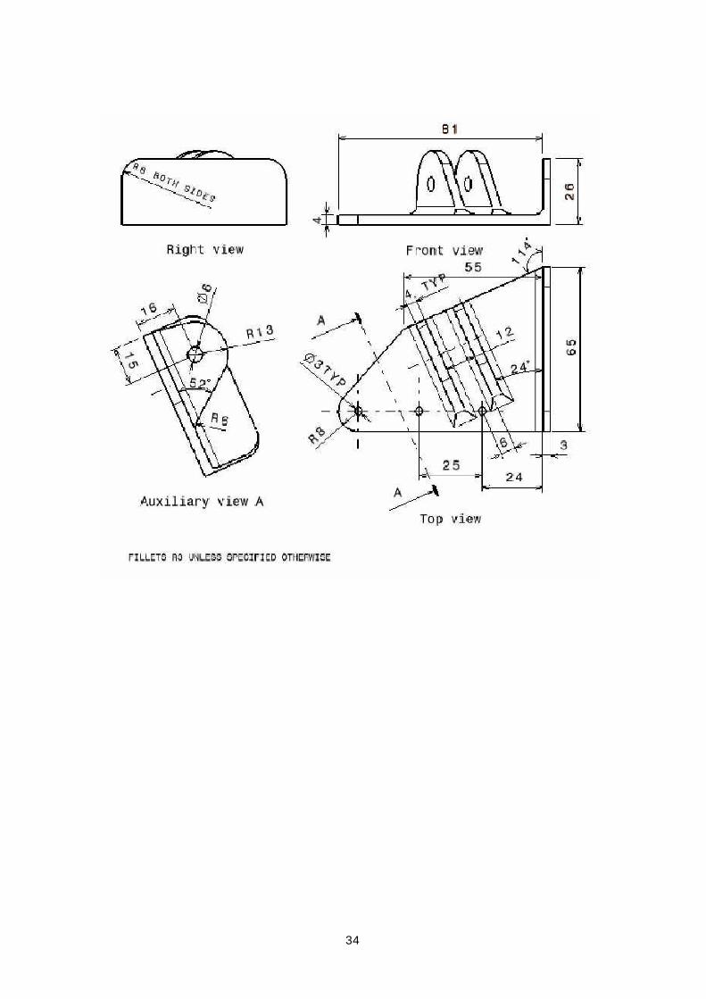
Connector Housing (1): Creating the Main Pad
and Other Features
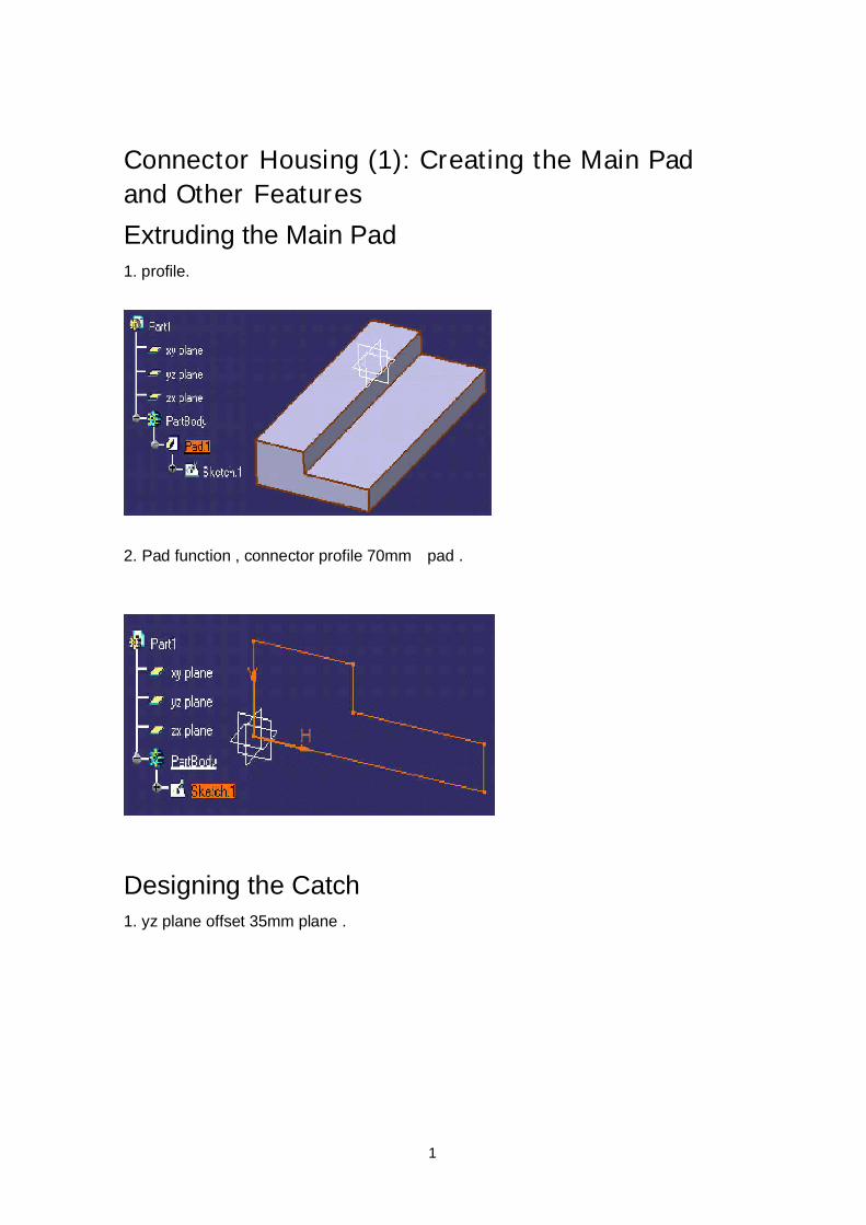
Extruding the Main Pad1. profile.
2. Pad function , connector profile 70mm pad .
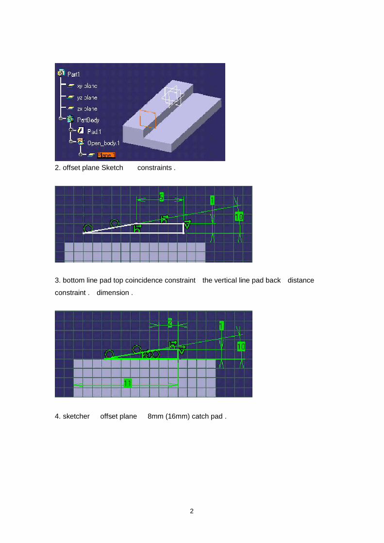
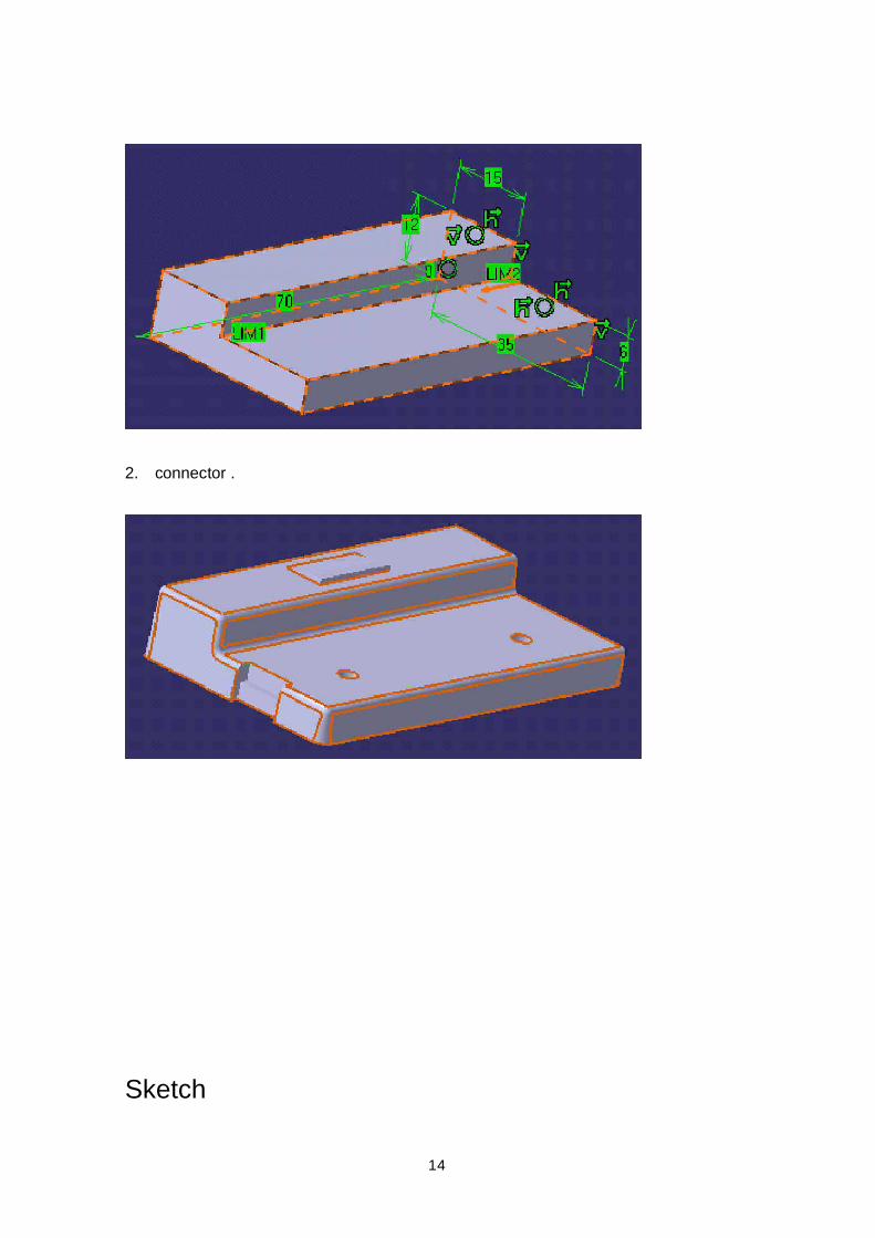
Designing the Catch1. yz plane offset 35mm plane .
2
2. offset plane Sketch constraints .
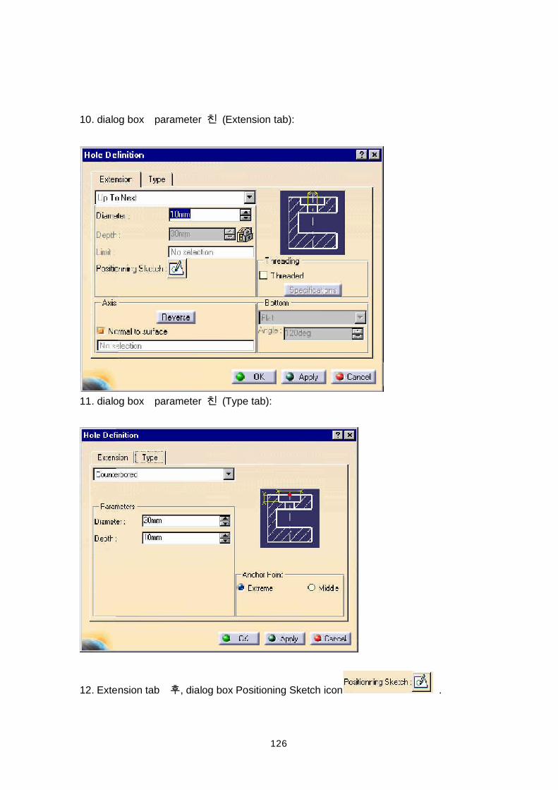
3. bottom line pad top coincidence constraint the vertical line pad back distanceconstraint . dimension .
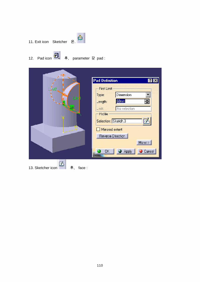
4. sketcher offset plane 8mm (16mm) catch pad .
3
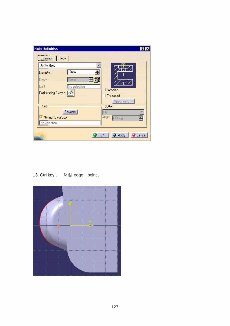
Hint: Mirrored Extent option
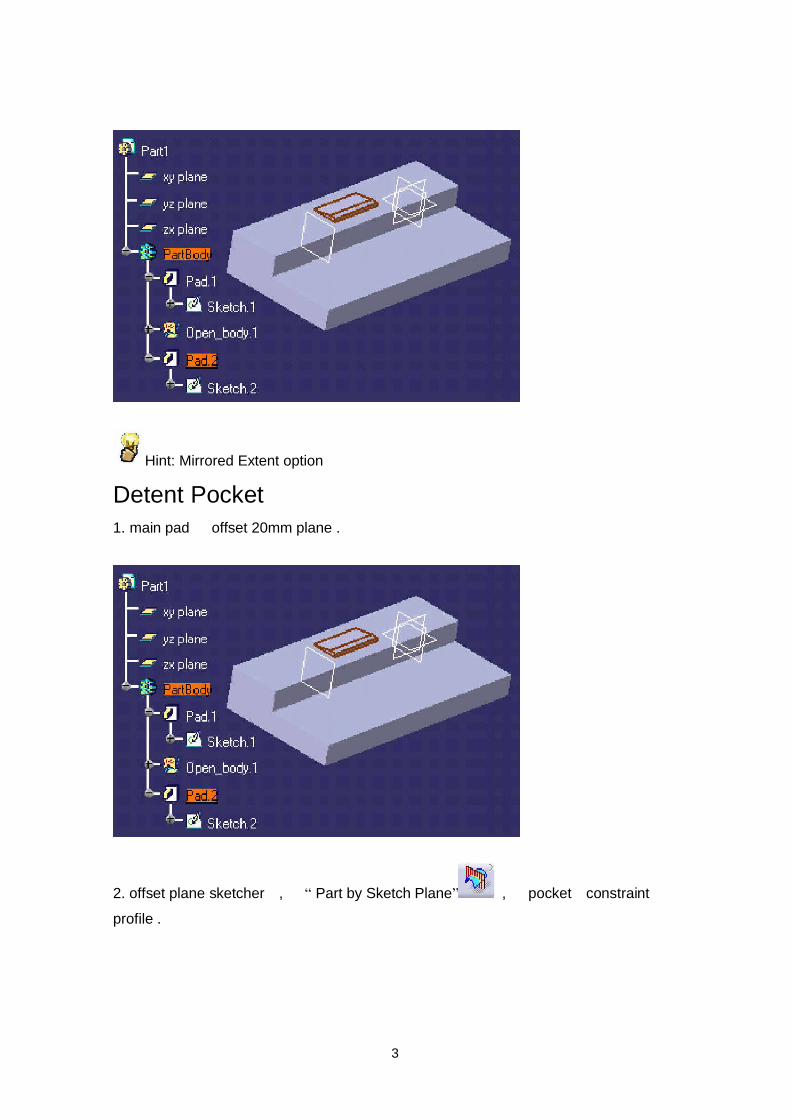
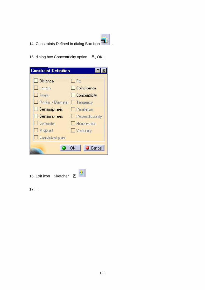
Detent Pocket1. main pad offset 20mm plane .
2. offset plane sketcher , Part by Sketch Plane , pocket constraintprofile .
4
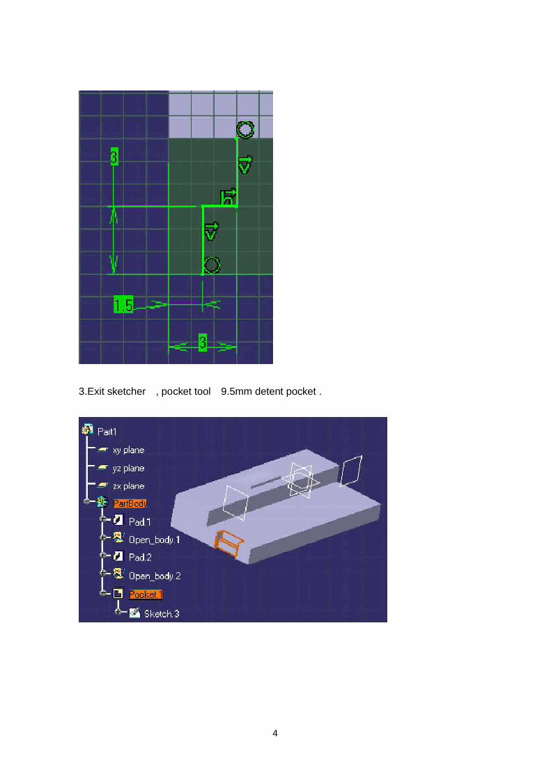
3.Exit sketcher , pocket tool 9.5mm detent pocket .
5
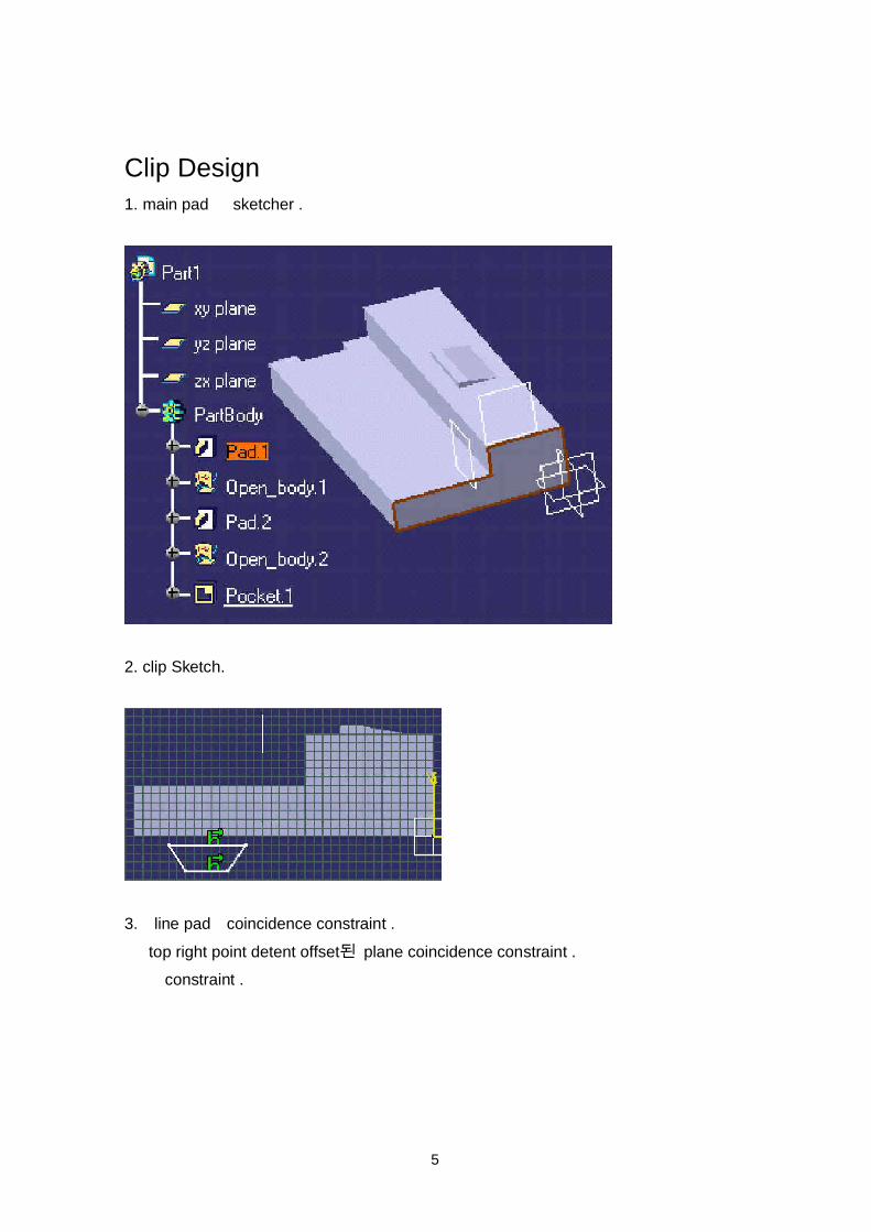
Clip Design1. main pad sketcher .
2. clip Sketch.
3. line pad coincidence constraint . top right point detent offset plane coincidence constraint . constraint .
6
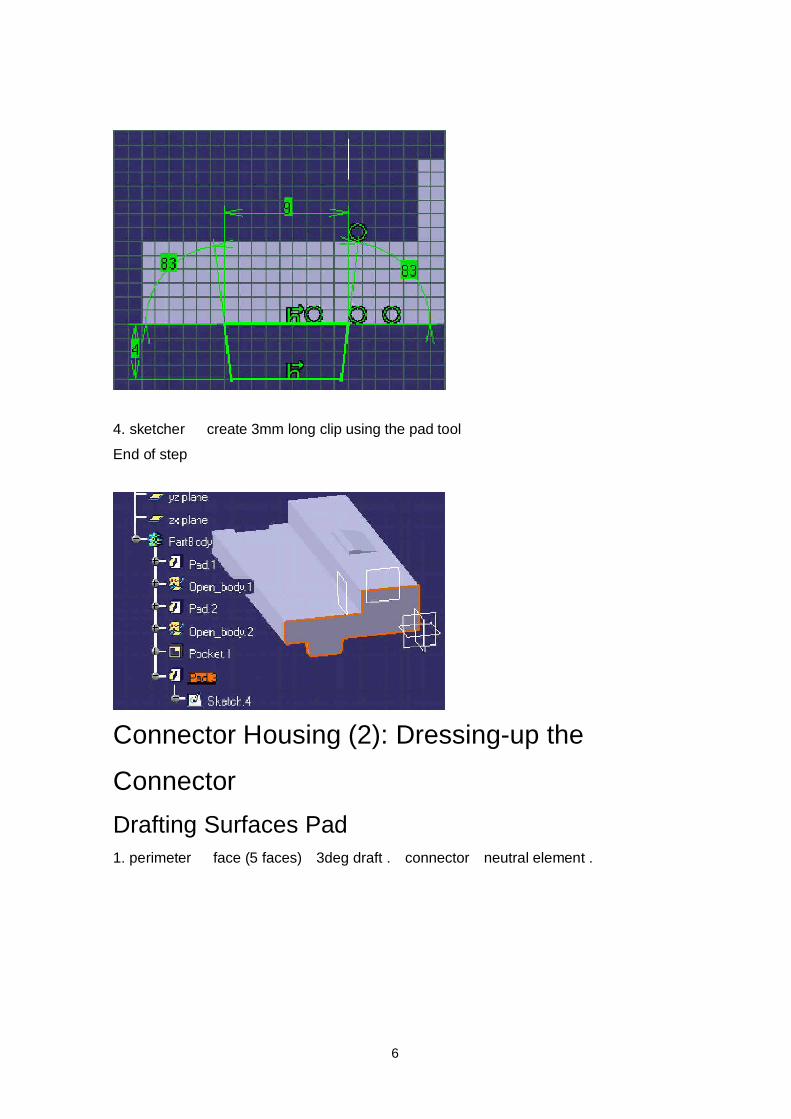
4. sketcher create 3mm long clip using the pad toolEnd of step
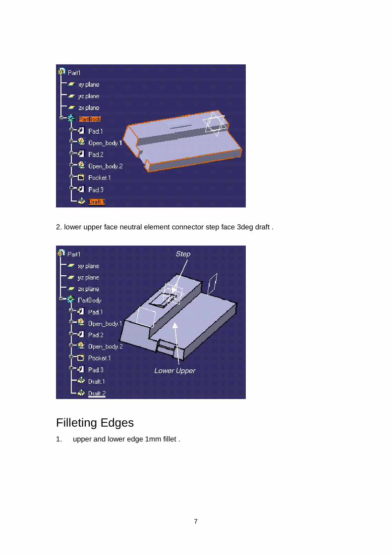
Connector Housing (2): Dressing-up theConnectorDrafting Surfaces Pad1. perimeter face (5 faces) 3deg draft . connector neutral element .
7
2. lower upper face neutral element connector step face 3deg draft .
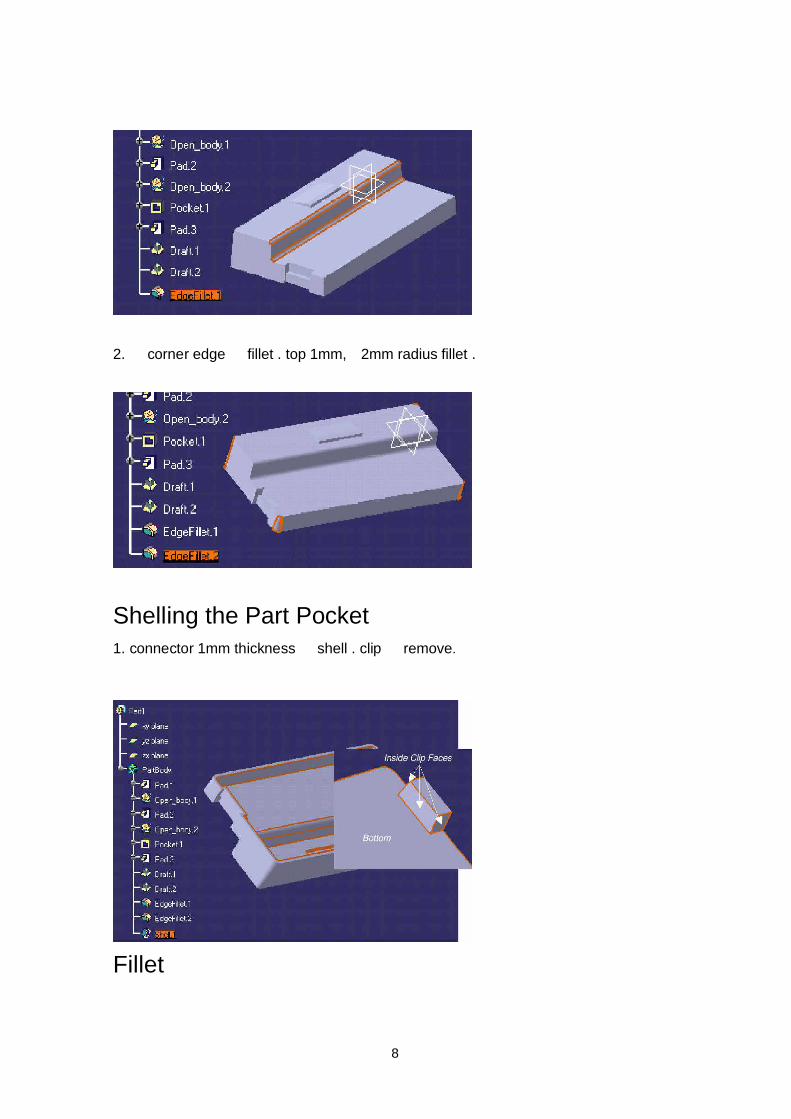
Filleting Edges1. upper and lower edge 1mm fillet .
8
2. corner edge fillet . top 1mm, 2mm radius fillet .
Shelling the Part Pocket1. connector 1mm thickness shell . clip remove.
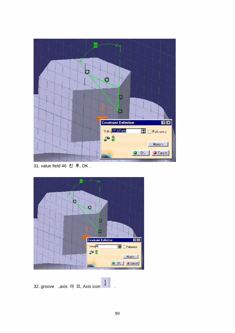
Fillet
9
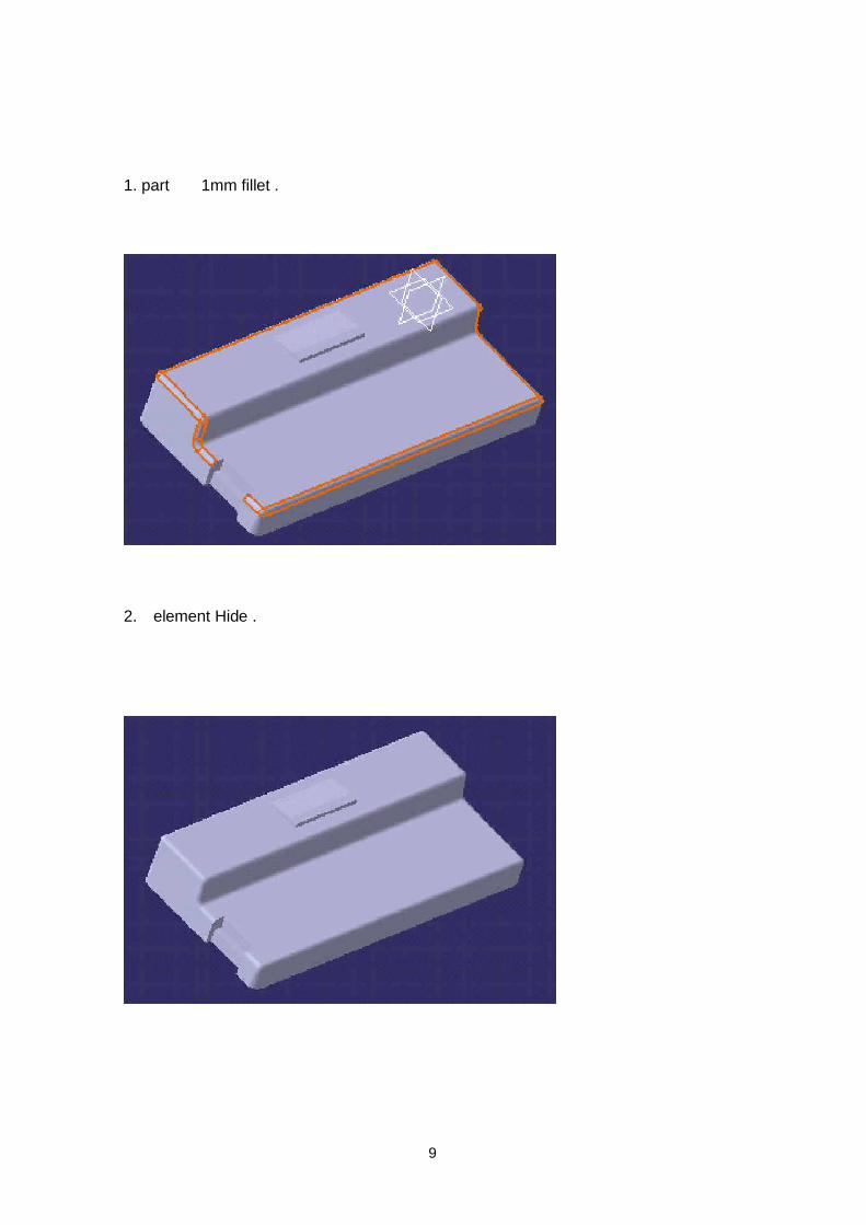
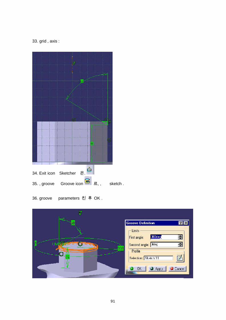
1. part 1mm fillet .
2. element Hide .
10
Creating a Hole
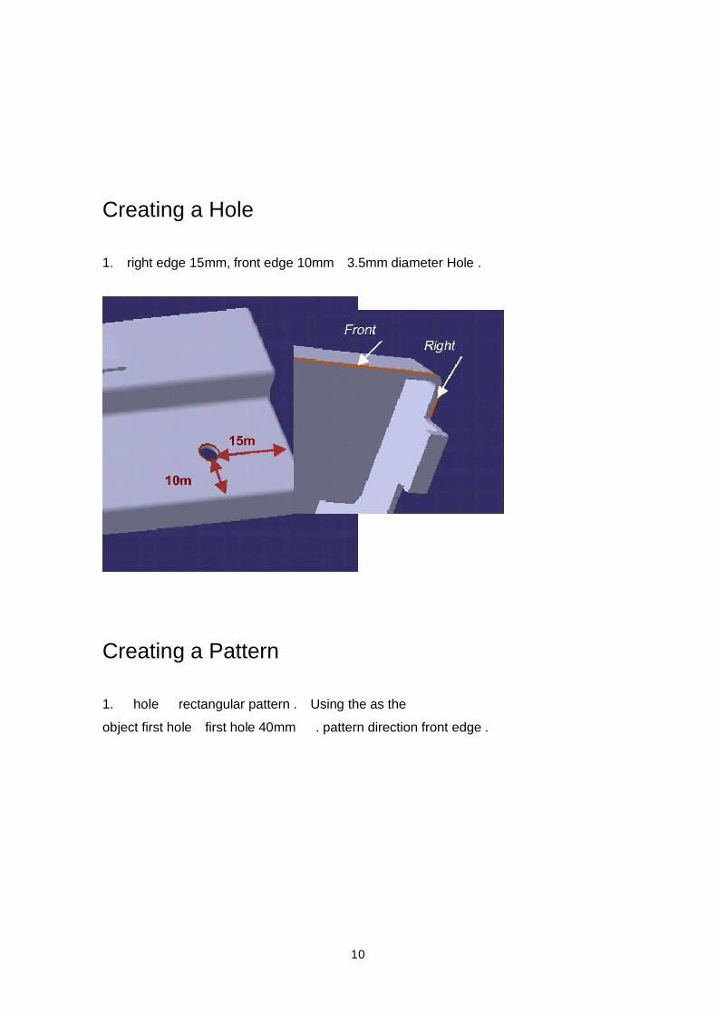
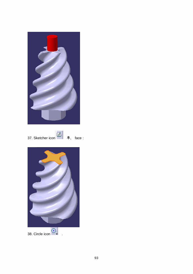
1. right edge 15mm, front edge 10mm 3.5mm diameter Hole .
Creating a Pattern
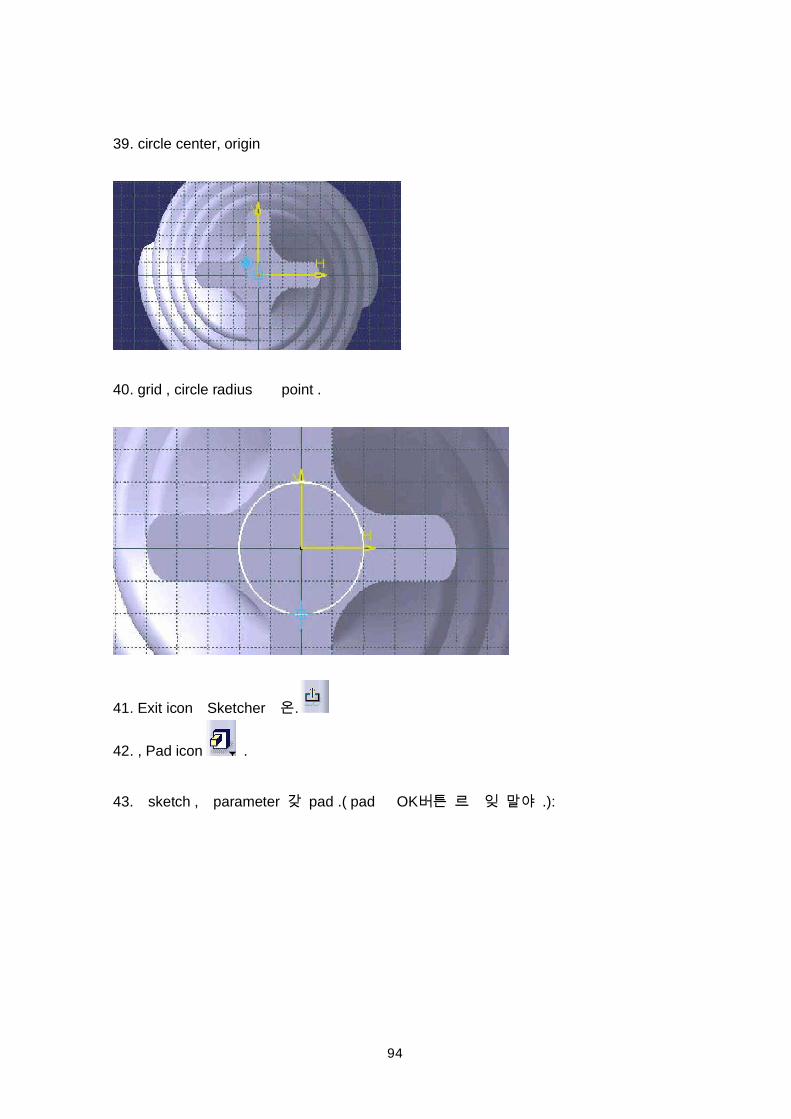
1. hole rectangular pattern . Using the as theobject first hole first hole 40mm . pattern direction front edge .
11
Adding Standoffs and Reordering
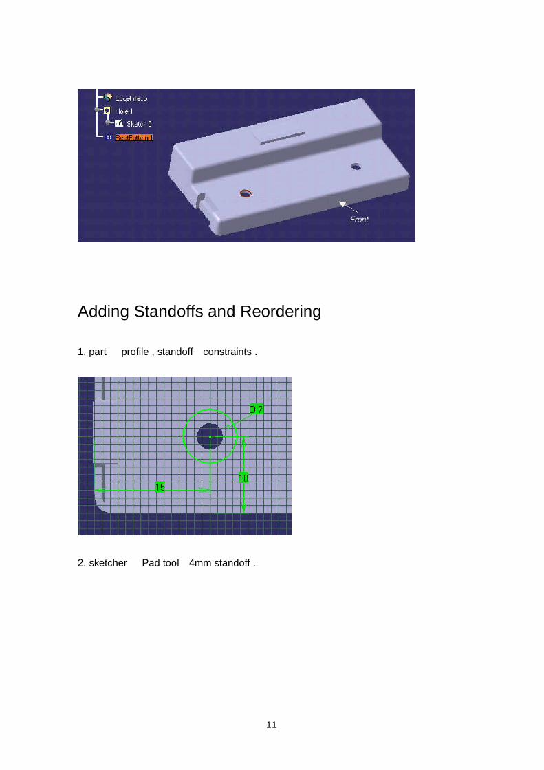
1. part profile , standoff constraints .
2. sketcher Pad tool 4mm standoff .
12
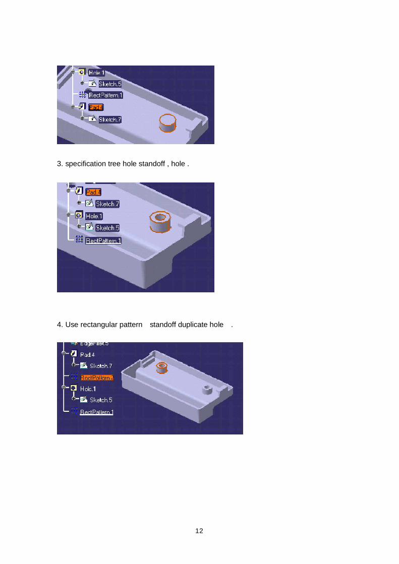
3. specification tree hole standoff , hole .
4. Use rectangular pattern standoff duplicate hole .

13
Connector Housing (3): Modifying the PartEditing Feature Parameters
1. First pad (Pad. 1) width 35mm 40mm .
14
2. connector .
Sketch
15
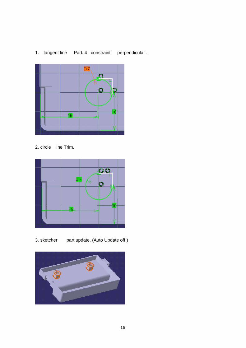
1. tangent line Pad. 4 . constraint perpendicular .
2. circle line Trim.
3. sketcher part update. (Auto Update off )
16
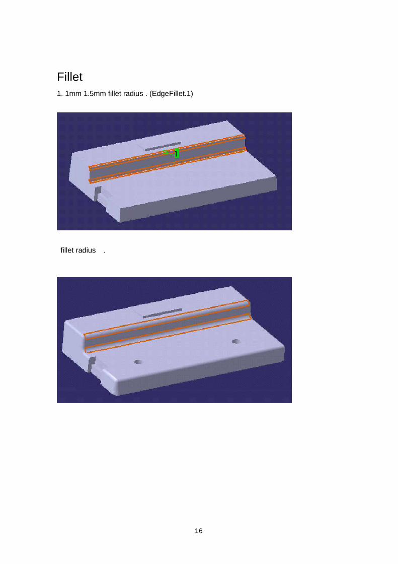
Fillet1. 1mm 1.5mm fillet radius . (EdgeFillet.1)
fillet radius .
17
Hole Type
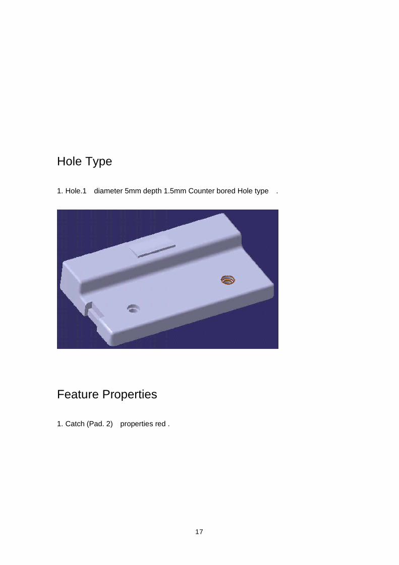
1. Hole.1 diameter 5mm depth 1.5mm Counter bored Hole type .
Feature Properties
1. Catch (Pad. 2) properties red .
18
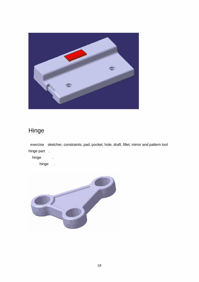
Hinge
exercise sketcher, constraints, pad, pocket, hole, draft, fillet, mirror and pattern toolhinge part . hinge . hinge .
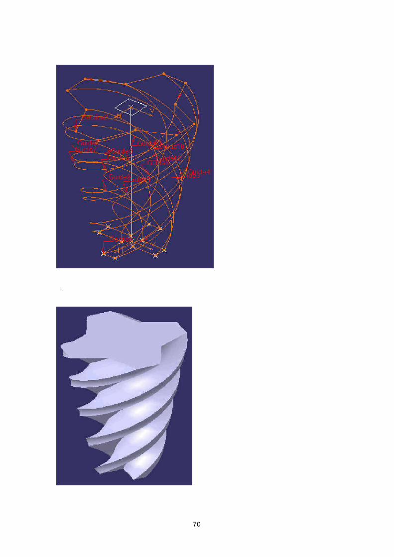
19
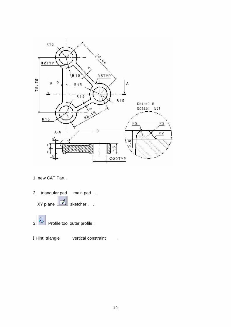
1. new CAT Part .
2. triangular pad main pad .
XY plane sketcher . .
3. Profile tool outer profile .
Ι Hint: triangle vertical constraint .
20
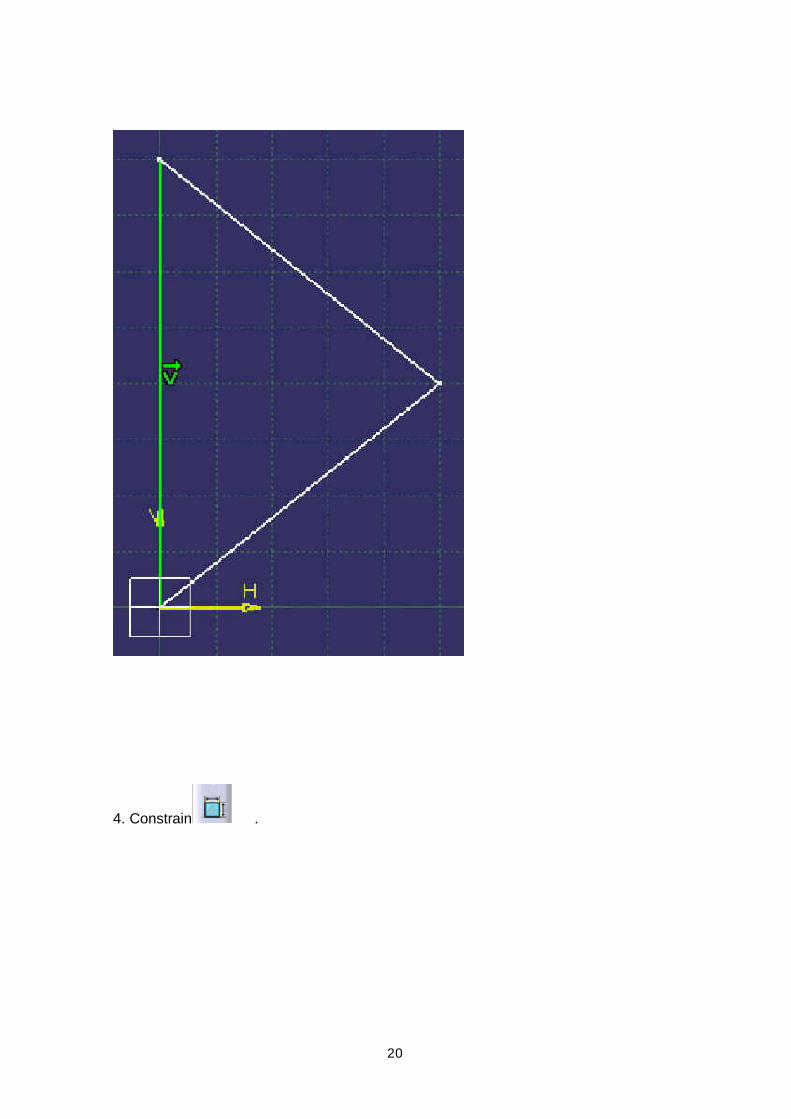
4. Constrain .
21
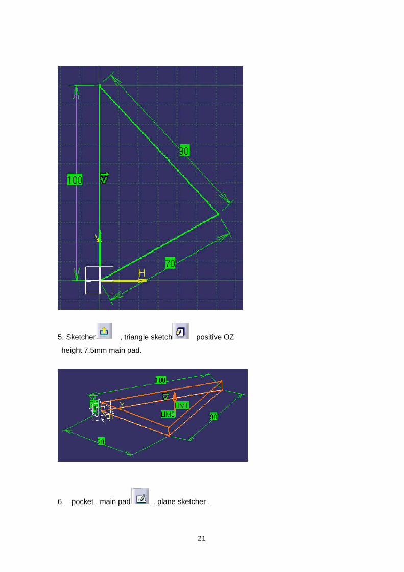
5. Sketcher , triangle sketch positive OZ height 7.5mm main pad.
6. pocket . main pad . plane sketcher .
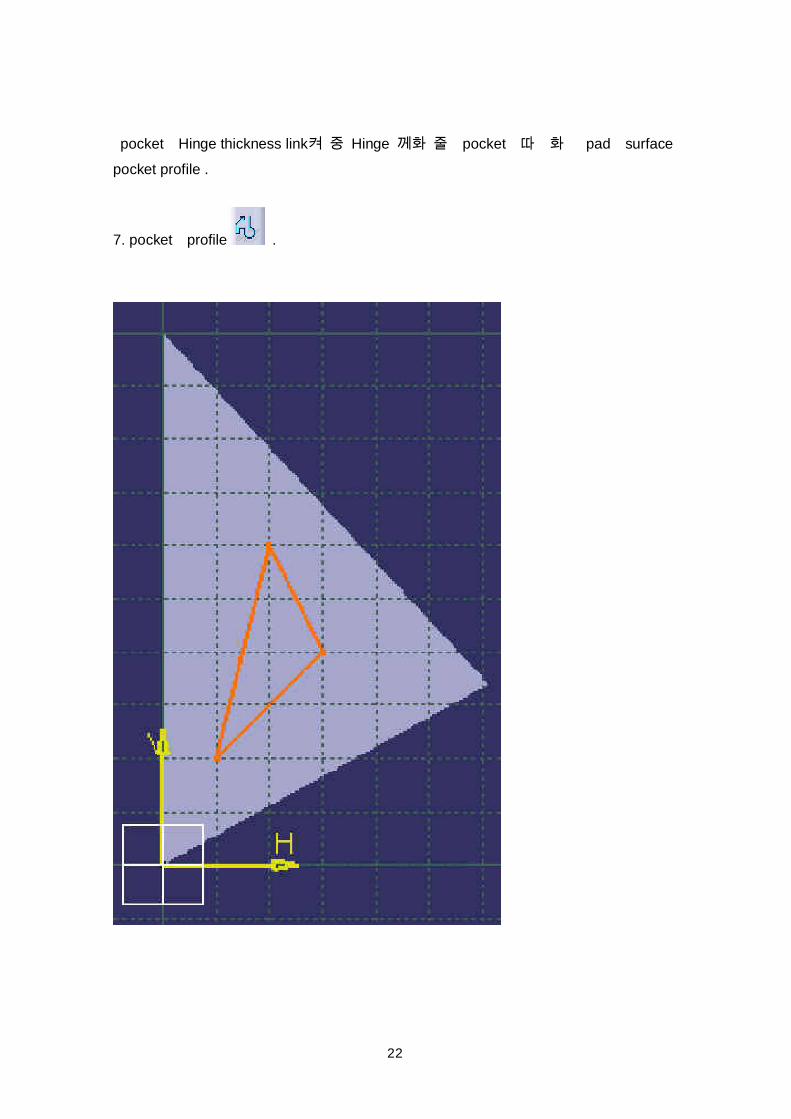
22
pocket Hinge thickness link Hinge pocket pad surfacepocket profile .
7. pocket profile .
23
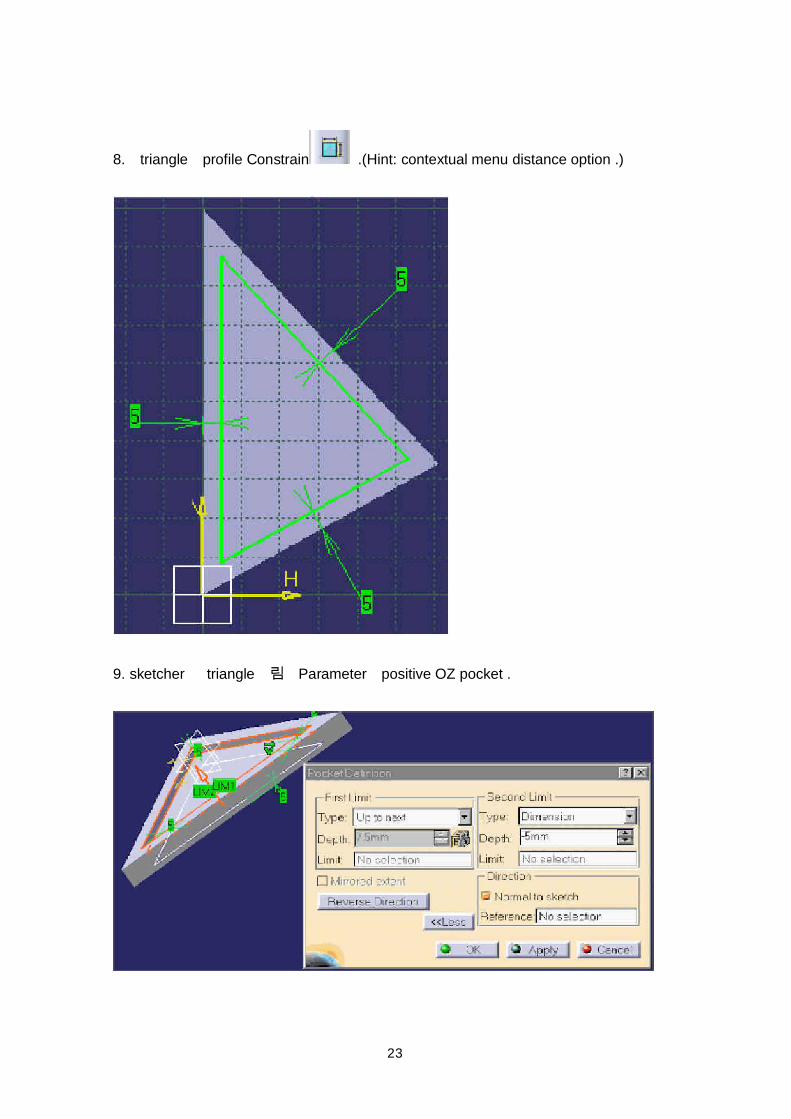
8. triangle profile Constrain .(Hint: contextual menu distance option .)
9. sketcher triangle Parameter positive OZ pocket .
24
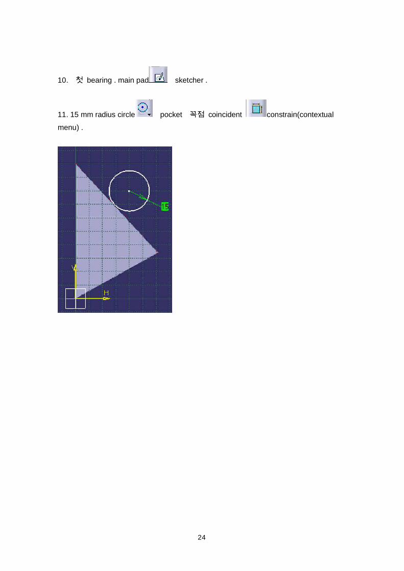
10. bearing . main pad sketcher .
11. 15 mm radius circle pocket coincident constrain(contextualmenu) .
25
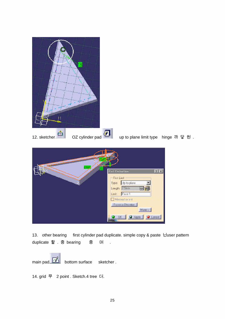
12. sketcher OZ cylinder pad up to plane limit type hinge .
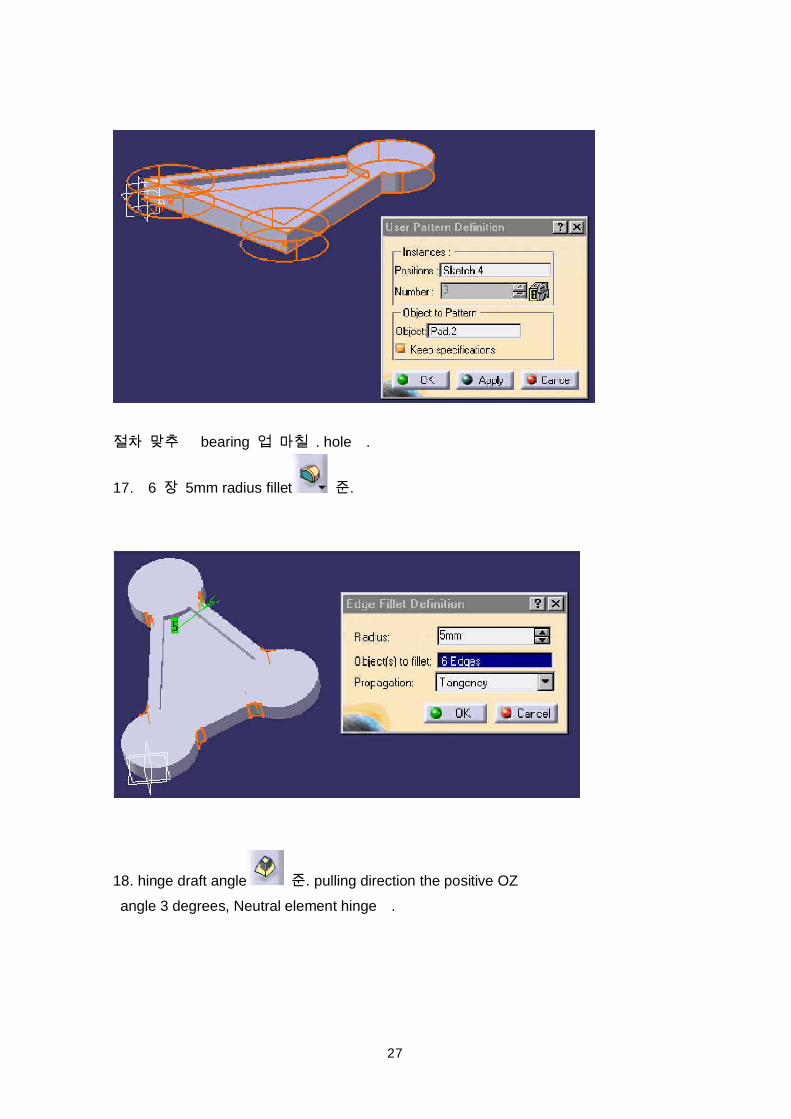
13. other bearing first cylinder pad duplicate. simple copy & paste user patternduplicate . bearing .
main pad bottom surface sketcher .
14. grid 2 point . Sketch.4 tree .
26
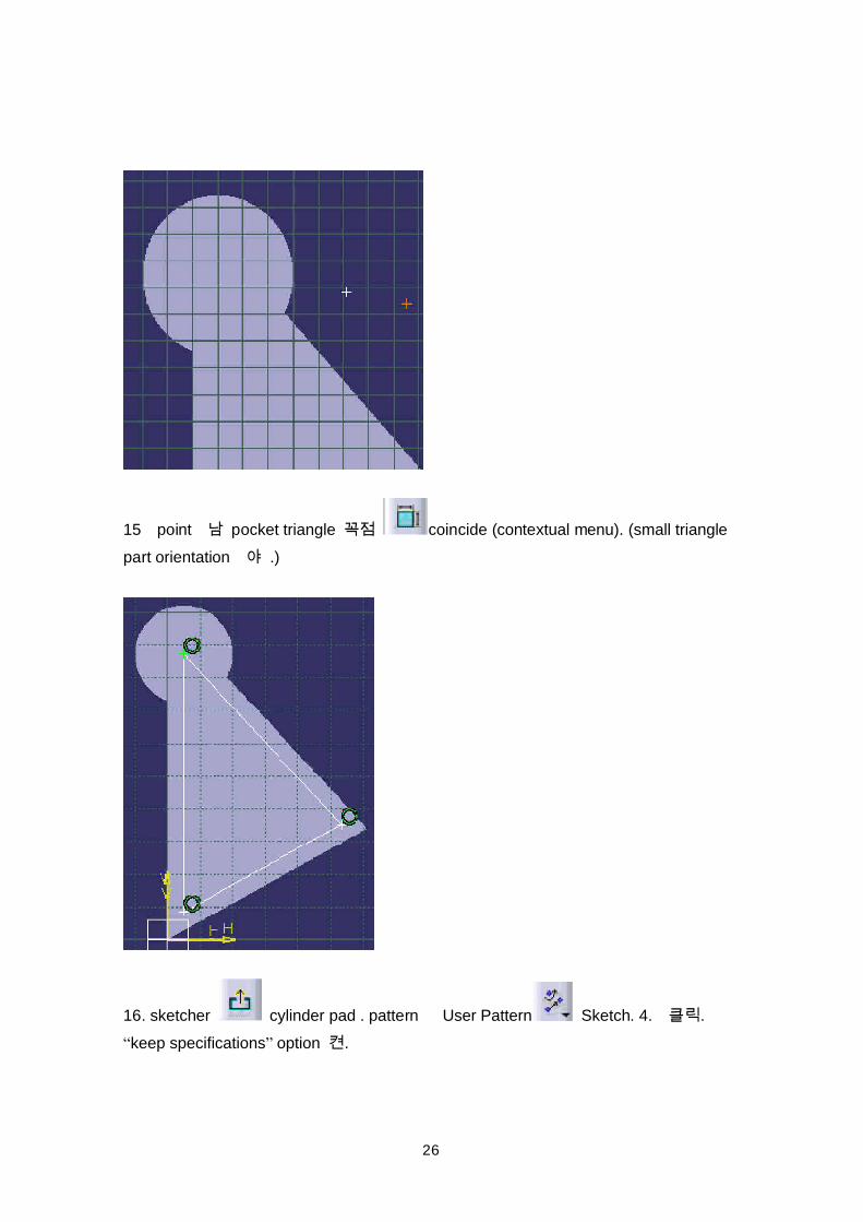
15 point pocket triangle coincide (contextual menu). (small trianglepart orientation .)
16. sketcher cylinder pad . pattern User Pattern Sketch. 4. .keep specifications option .
27
bearing . hole .
17. 6 5mm radius fillet .
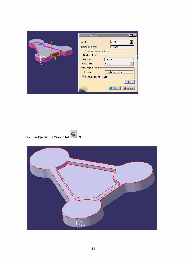
18. hinge draft angle . pulling direction the positive OZ angle 3 degrees, Neutral element hinge .
28
19. edge radius 2mm fillet .
29
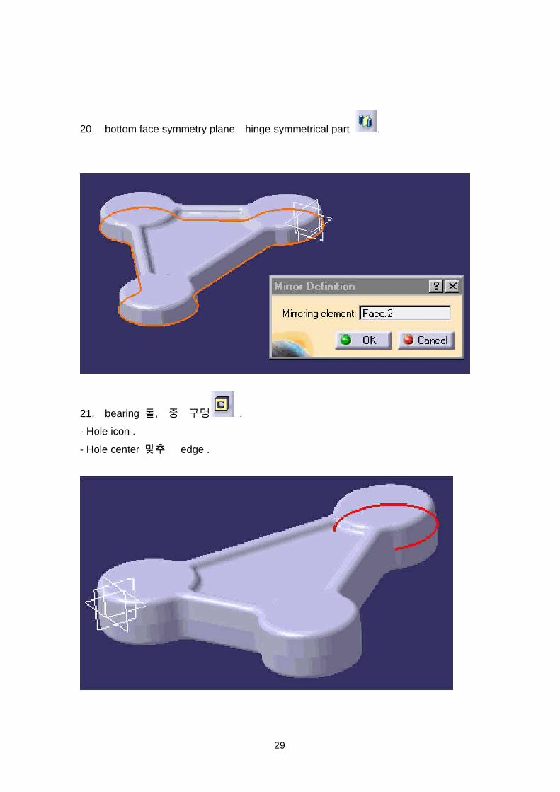
20. bottom face symmetry plane hinge symmetrical part .
21. bearing , .- Hole icon .- Hole center edge .
30
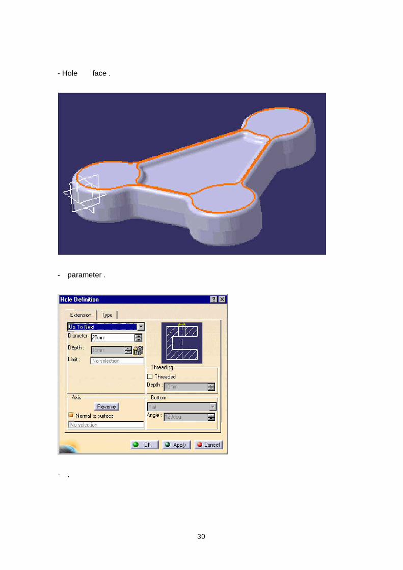
- Hole face .
- parameter .
- .
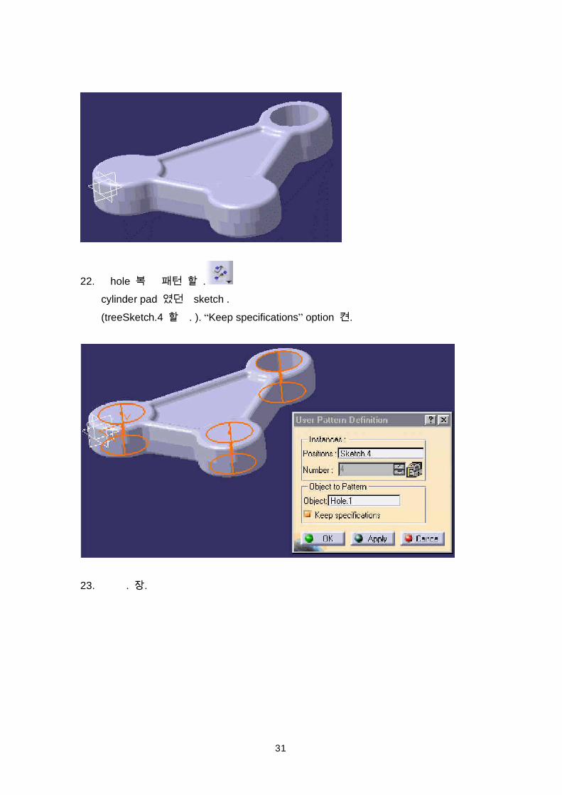
31
22. hole .cylinder pad sketch .(treeSketch.4 . ). Keep specifications option .
23. . .
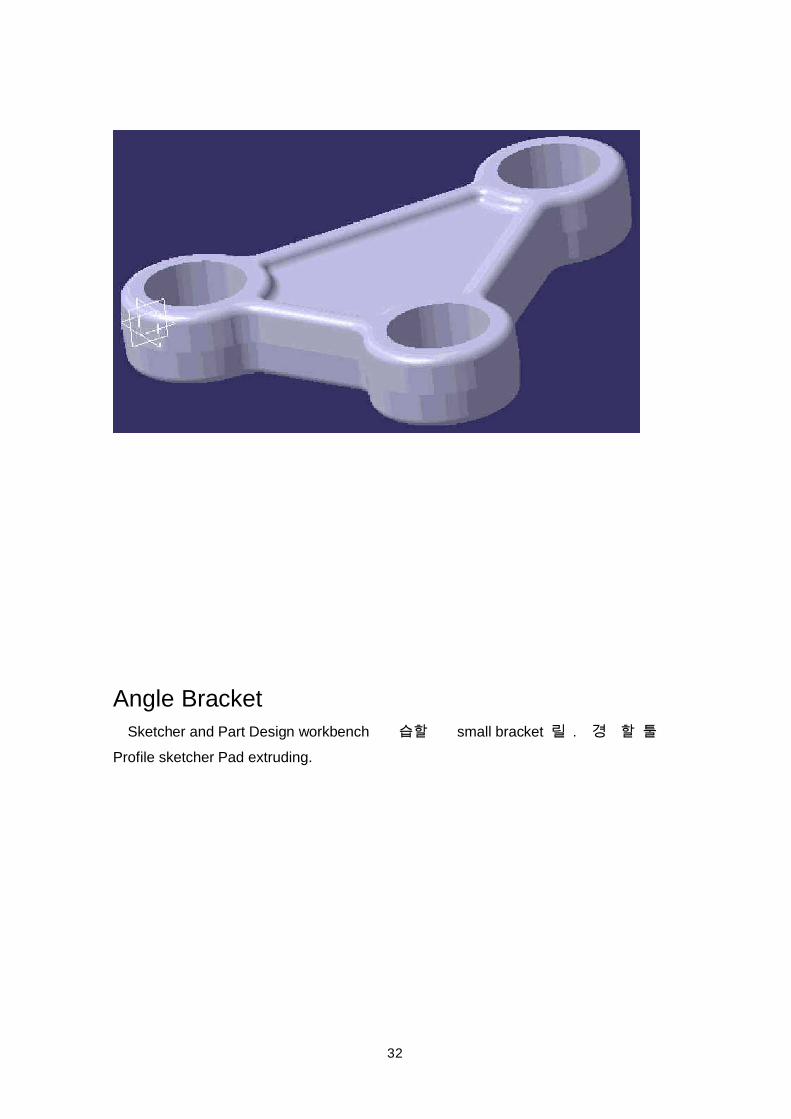
32
Angle Bracket Sketcher and Part Design workbench small bracket . Profile sketcher Pad extruding.
33
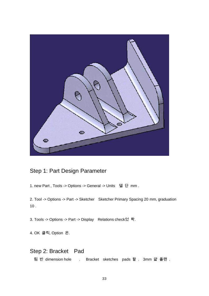
Step 1: Part Design Parameter
1. new Part , Tools -> Options -> General -> Units mm .
2. Tool -> Options -> Part -> Sketcher Sketcher Primary Spacing 20 mm, graduation10 .
3. Tools -> Options -> Part -> Display Relations check .
4. OK , Option .
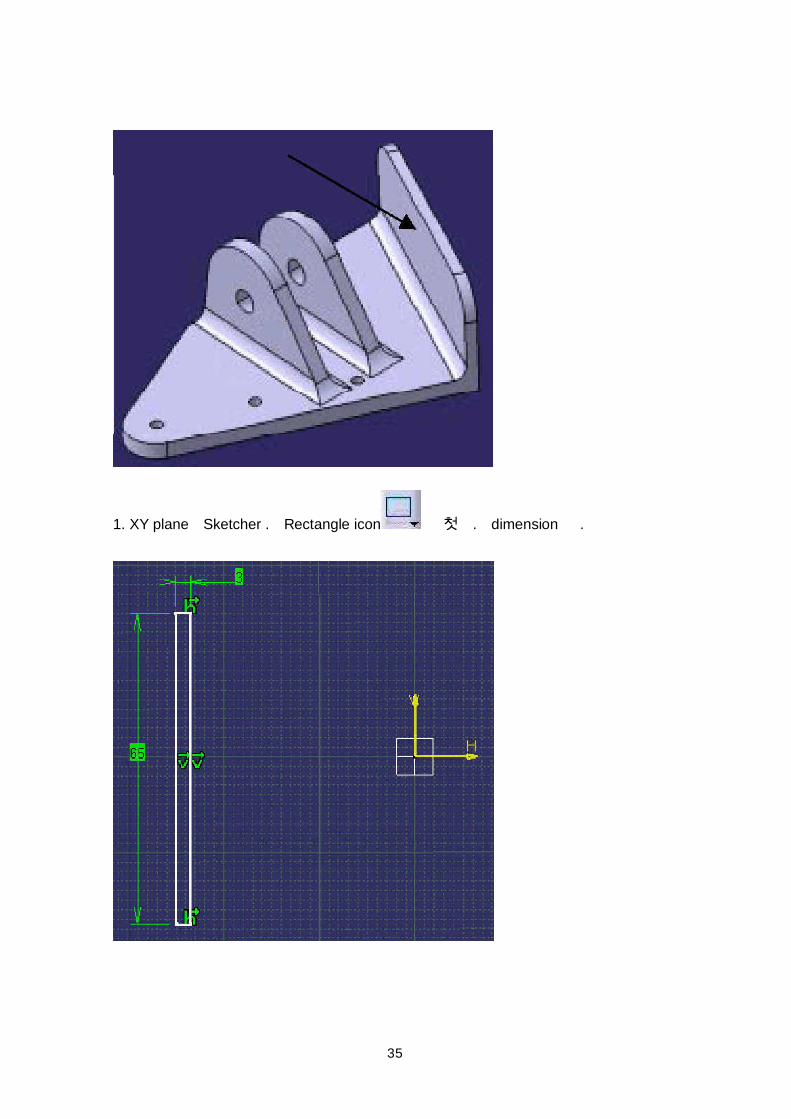
Step 2: Bracket Pad dimension hole . Bracket sketches pads . 3mm .
34
35
1. XY plane Sketcher . Rectangle icon . dimension .
36
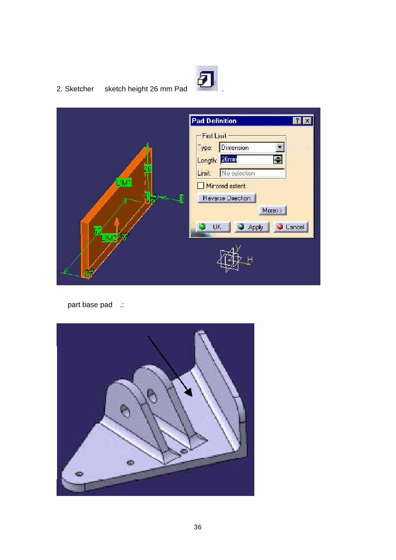
2. Sketcher sketch height 26 mm Pad .
part base pad .:
37
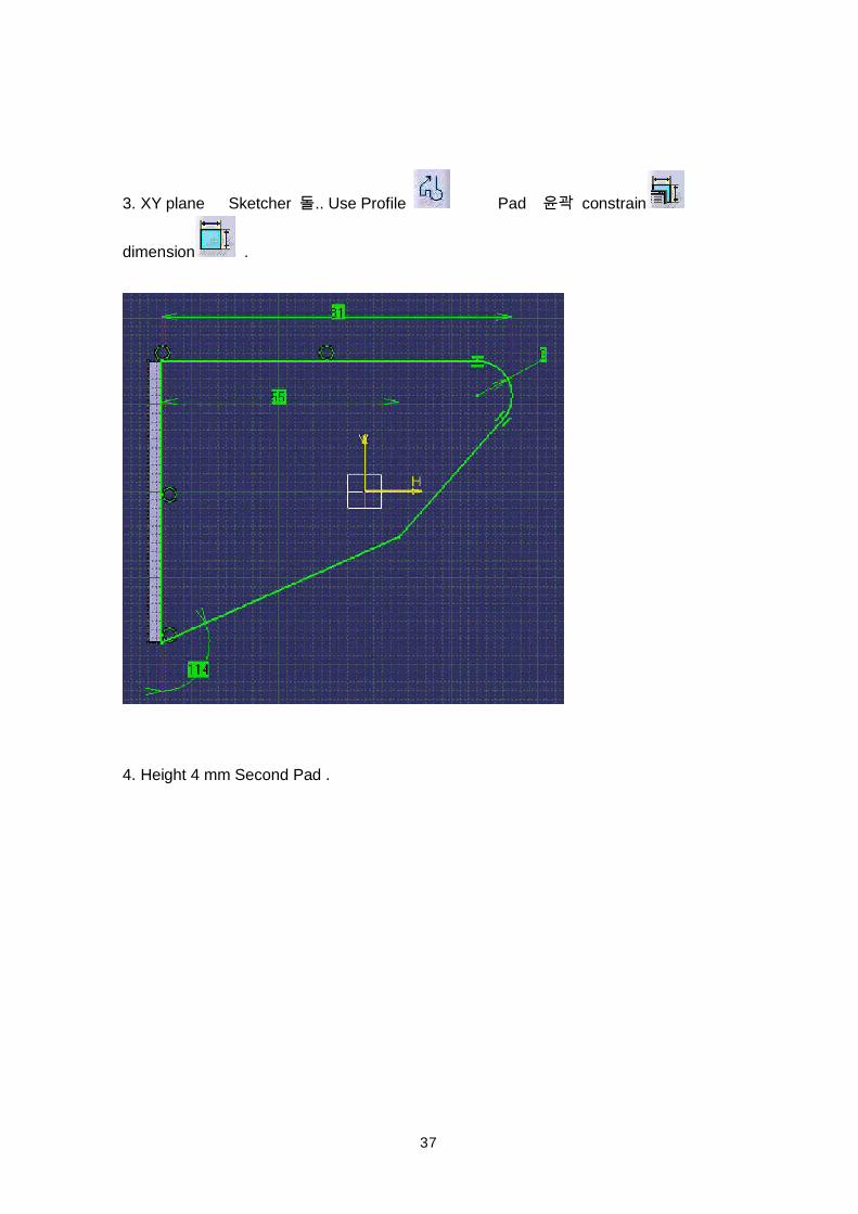
3. XY plane Sketcher .. Use Profile Pad constrain
dimension .
4. Height 4 mm Second Pad .
38
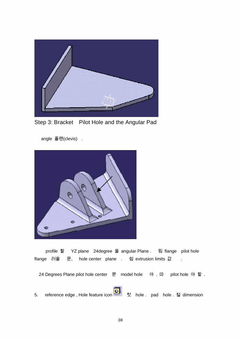
Step 3: Bracket Pilot Hole and the Angular Pad
angle (clevis) .
profile YZ plane 24degree angular Plane . flange pilot holeflange , hole center plane . extrusion limits .
24 Degrees Plane pilot hole center model hole . pilot hole .
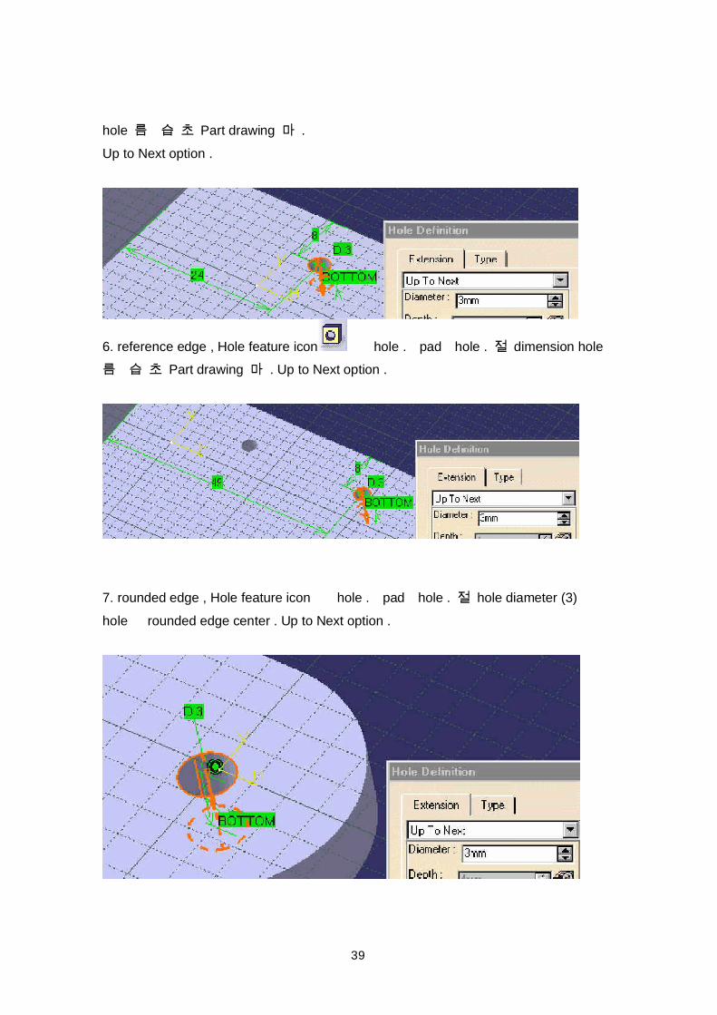
5. reference edge , Hole feature icon hole . pad hole . dimension
39
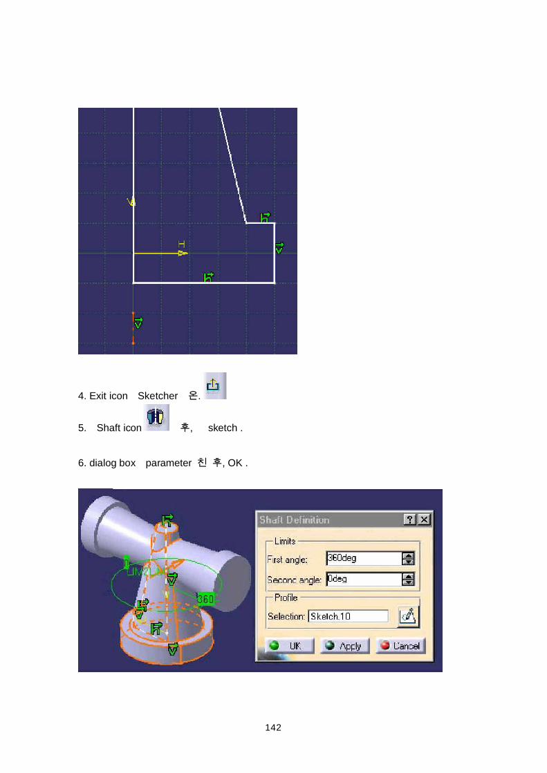
hole Part drawing .Up to Next option .
6. reference edge , Hole feature icon hole . pad hole . dimension hole Part drawing . Up to Next option .
7. rounded edge , Hole feature icon hole . pad hole . hole diameter (3)hole rounded edge center . Up to Next option .
40
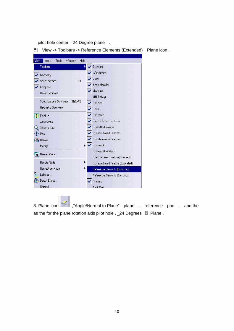
pilot hole center 24 Degree plane . View -> Toolbars -> Reference Elements (Extended) Plane icon .
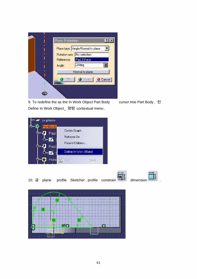
8. Plane icon ,”Angle/Normal to Plane” plane ._. reference pad . and theas the for the plane rotation axis pilot hole . _24 Degrees Plane .
41
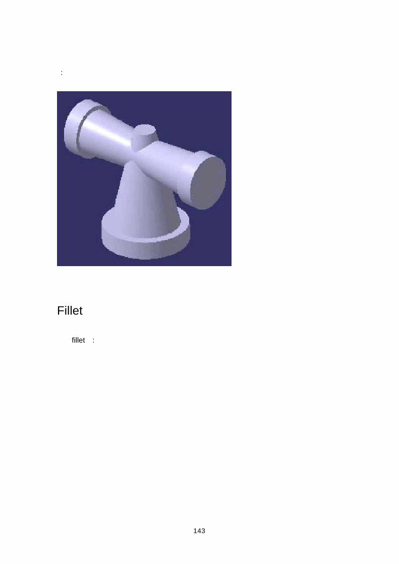
9. To redefine the as the In Work Object Part Body cursor tree Part Body . Define In Work Object_ contextual menu .
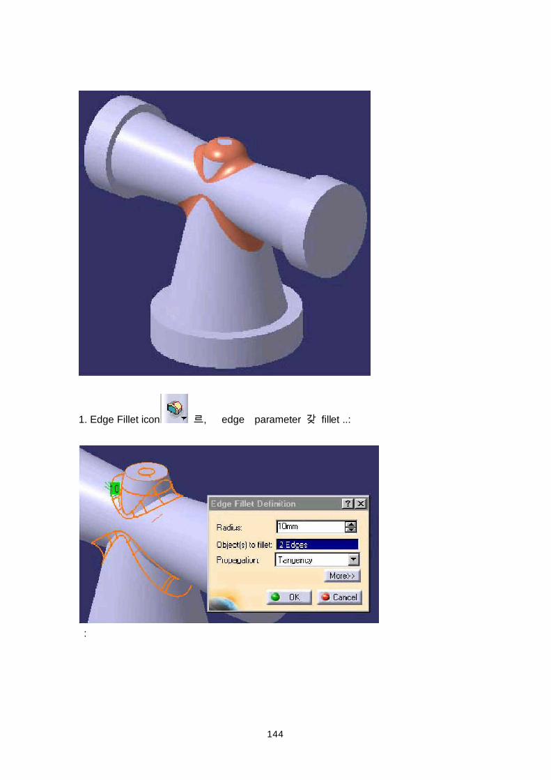
10. plane profile Sketcher . profile constrain dimension .
42
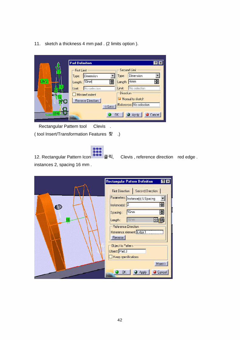
11. sketch a thickness 4 mm pad . (2 limits option ).
Rectangular Pattern tool Clevis .( tool Insert/Transformation Features .)
12. Rectangular Pattern Icon , Clevis , reference direction red edge .instances 2, spacing 16 mm .
43
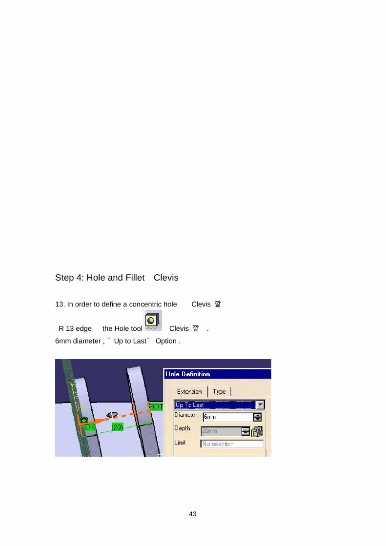
Step 4: Hole and Fillet Clevis
13. In order to define a concentric hole Clevis
R 13 edge the Hole tool Clevis .6mm diameter , Up to Last Option .
44
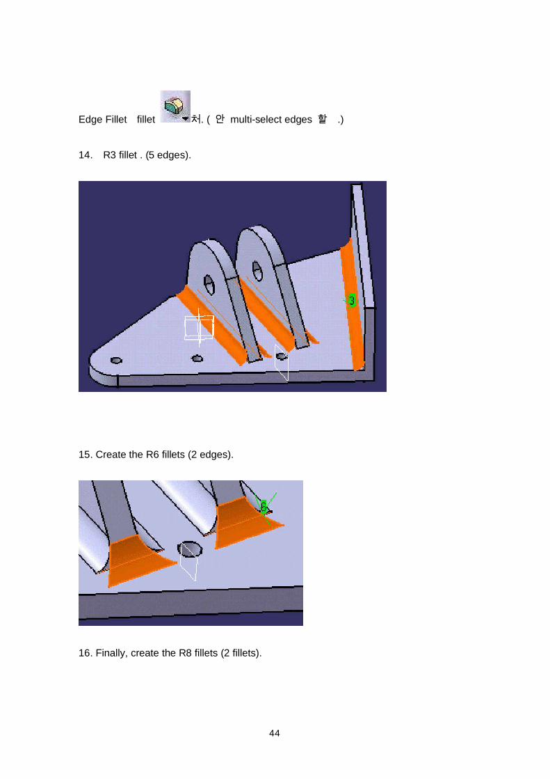
Edge Fillet fillet . ( multi-select edges .)
14. R3 fillet . (5 edges).
15. Create the R6 fillets (2 edges).
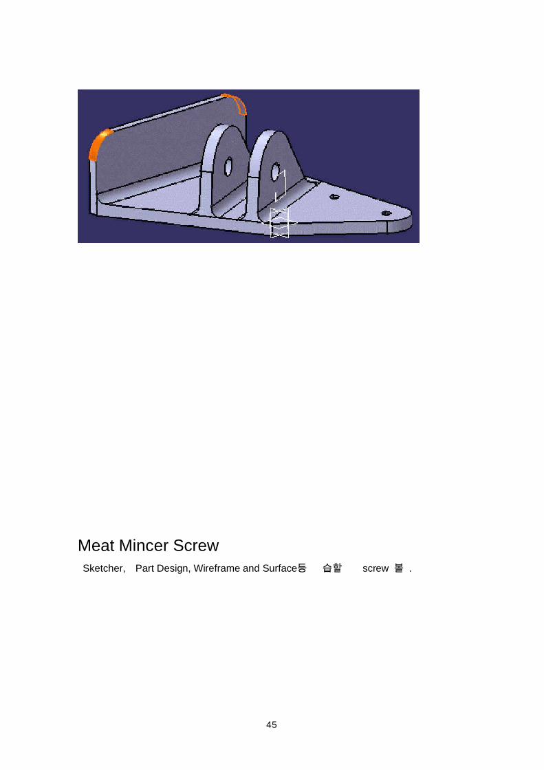
16. Finally, create the R8 fillets (2 fillets).
45
Meat Mincer Screw Sketcher, Part Design, Wireframe and Surface screw .
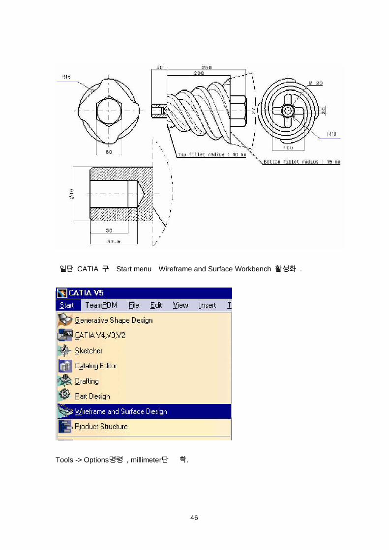
46
CATIA Start menu Wireframe and Surface Workbench .
Tools -> Options , millimeter .
47
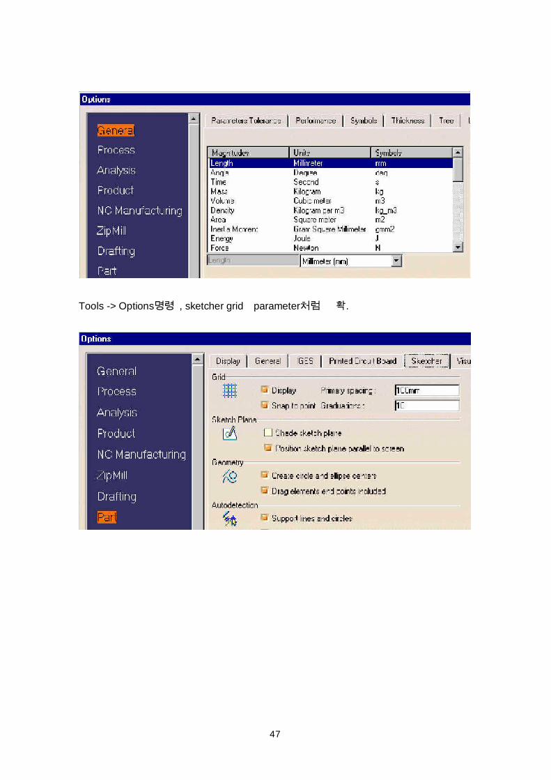
Tools -> Options , sketcher grid parameter .
48
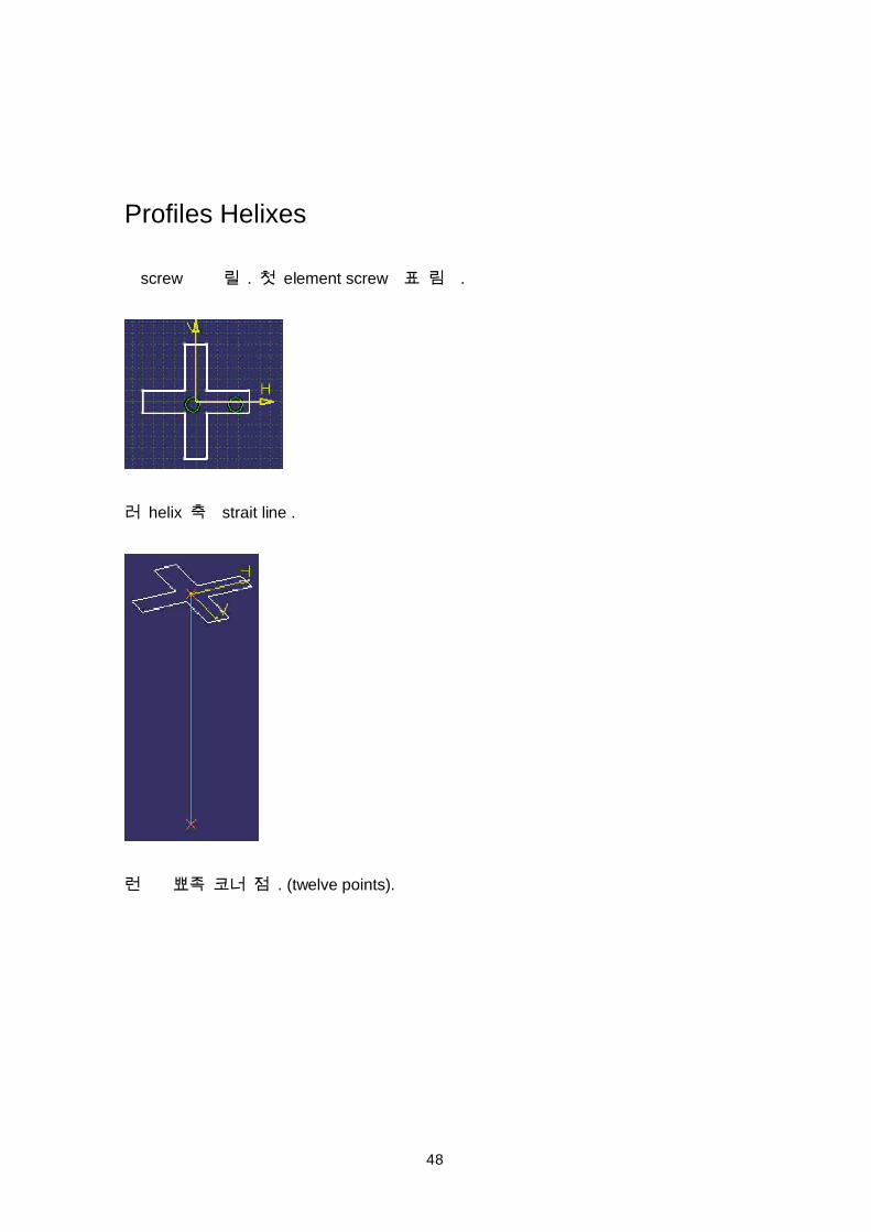
Profiles Helixes
screw . element screw .
helix strait line .
. (twelve points).
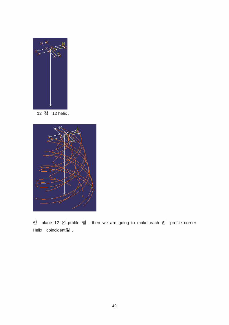
49
12 12 helix .
plane 12 profile . then we are going to make each profile cornerHelix coincident .
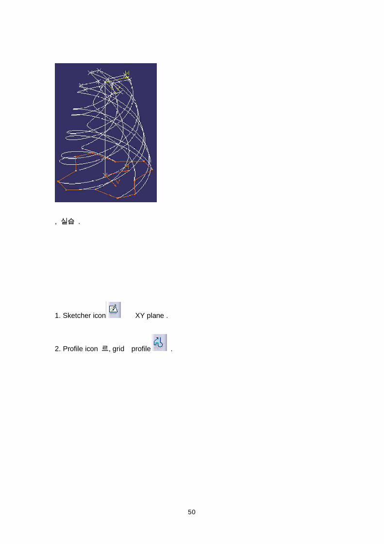
50
, .
1. Sketcher icon XY plane .
2. Profile icon , grid profile .
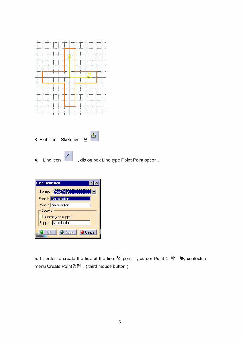
51
3. Exit icon Sketcher .
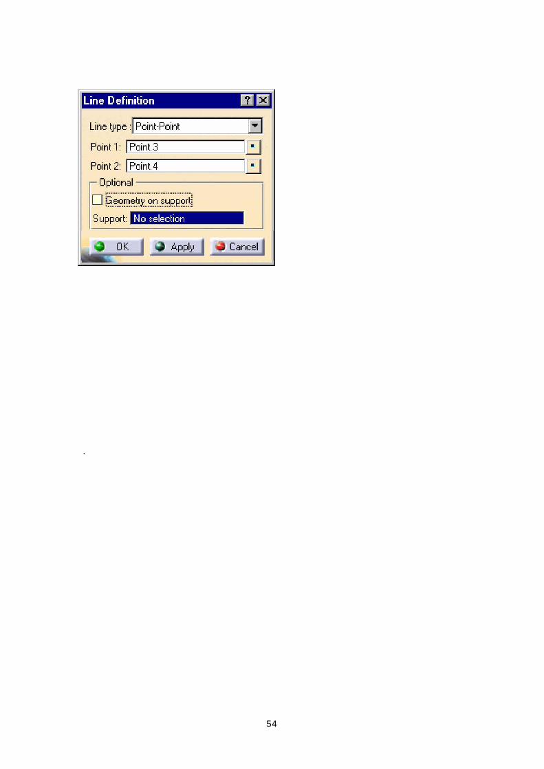
4. Line icon , dialog box Line type Point-Point option .
5. In order to create the first of the line point , cursor Point 1 , contextualmenu Create Point . ( third mouse button )
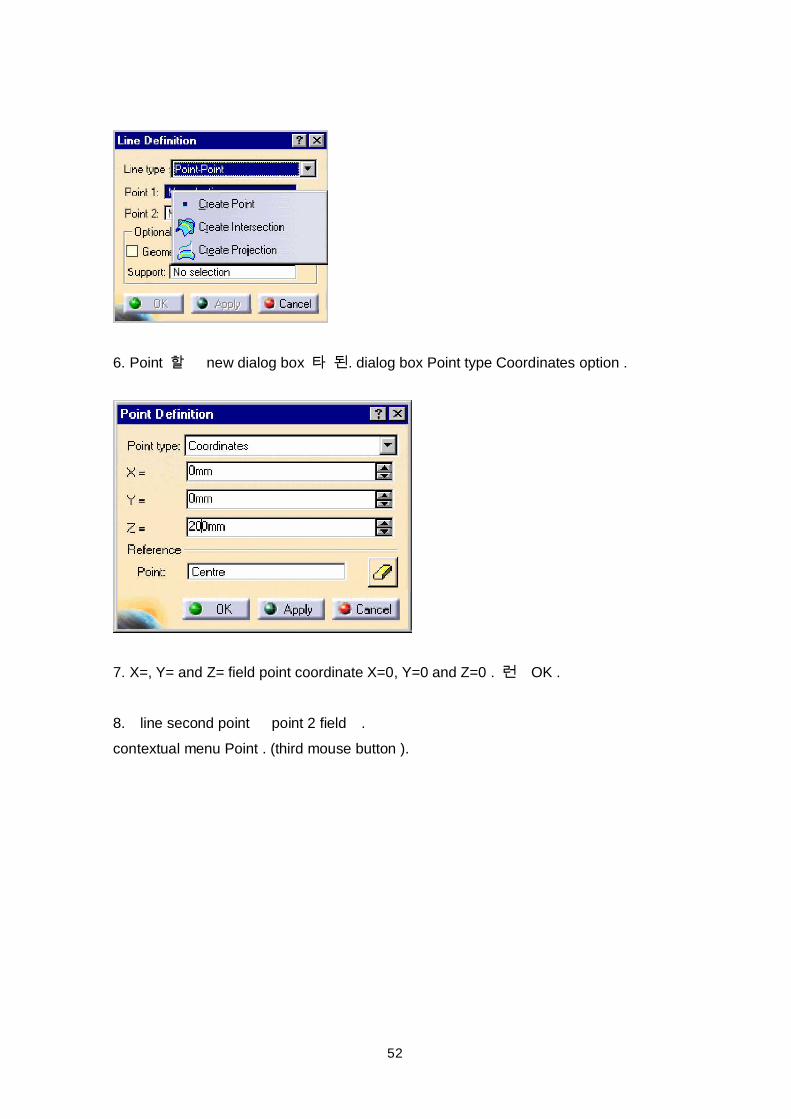
52
6. Point new dialog box . dialog box Point type Coordinates option .
7. X=, Y= and Z= field point coordinate X=0, Y=0 and Z=0 . OK .
8. line second point point 2 field .contextual menu Point . (third mouse button ).
53
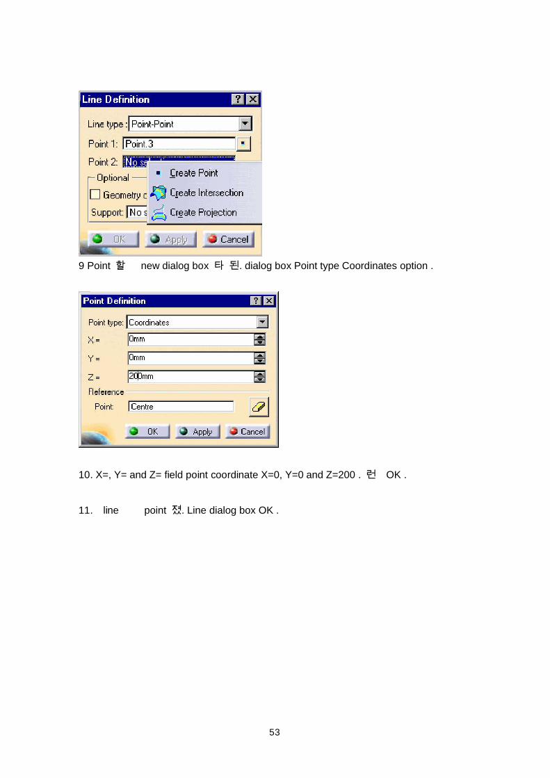
9 Point new dialog box . dialog box Point type Coordinates option .
10. X=, Y= and Z= field point coordinate X=0, Y=0 and Z=200 . OK .
11. line point . Line dialog box OK .
54
.
55
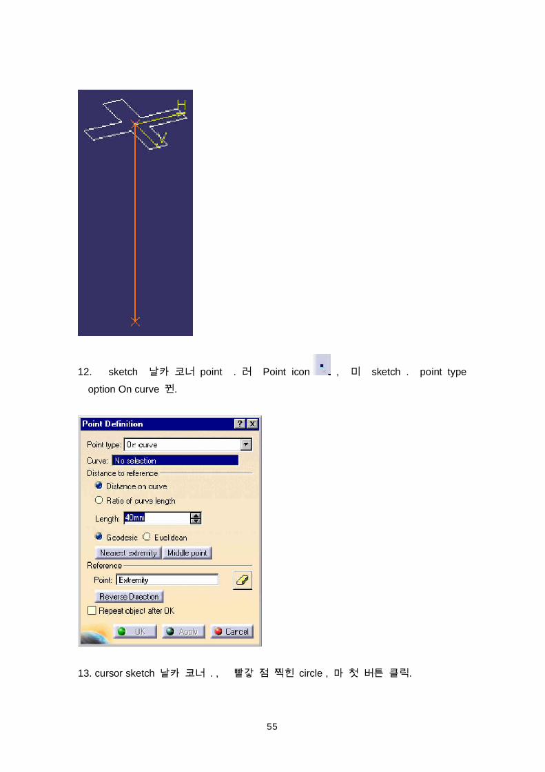
12. sketch point . Point icon , sketch . point typeoption On curve .
13. cursor sketch . , circle , .
56
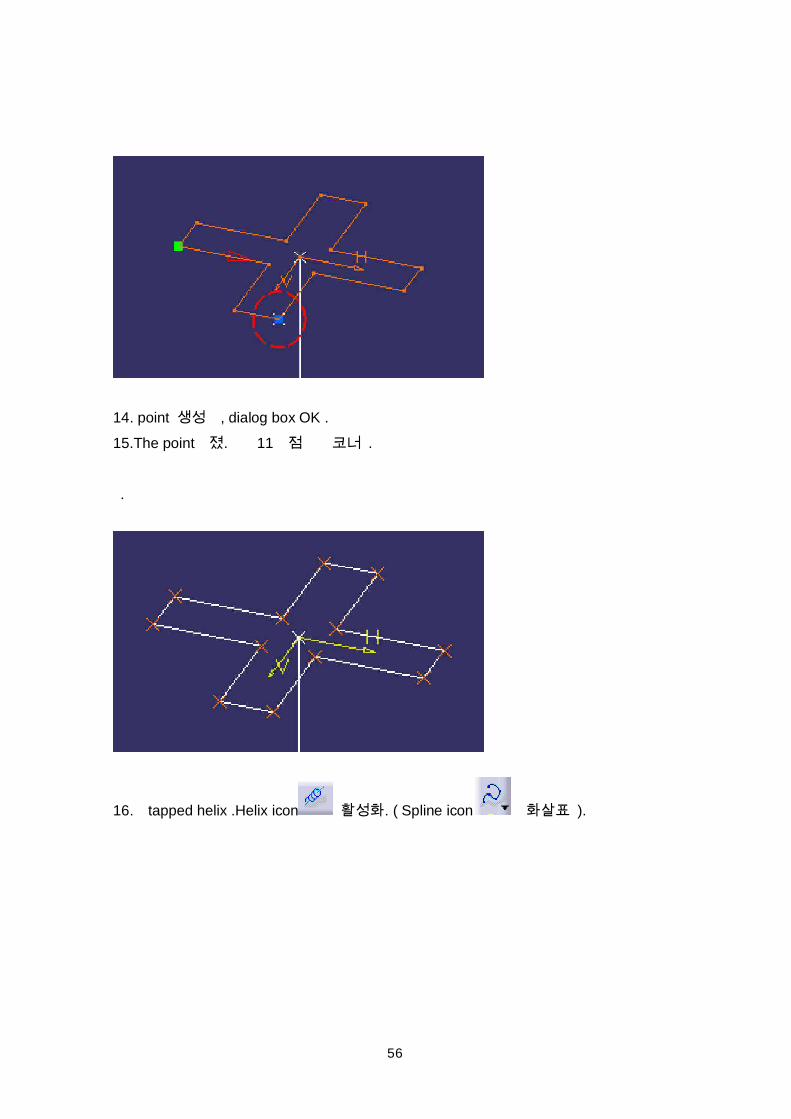
14. point , dialog box OK .15.The point . 11 .
.
16. tapped helix .Helix icon . ( Spline icon ).
57
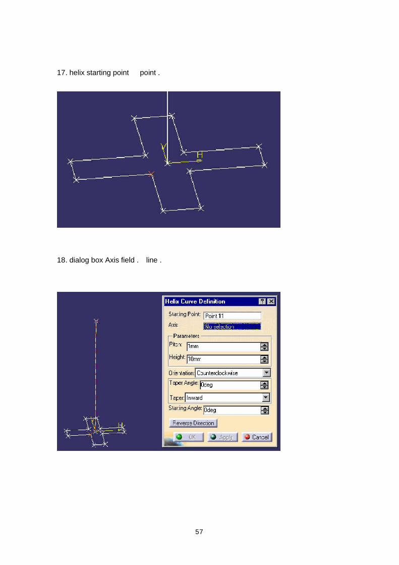
17. helix starting point point .
18. dialog box Axis field . line .
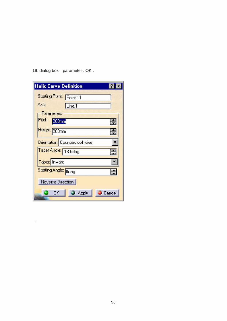
58
19. dialog box parameter . OK .
.
59
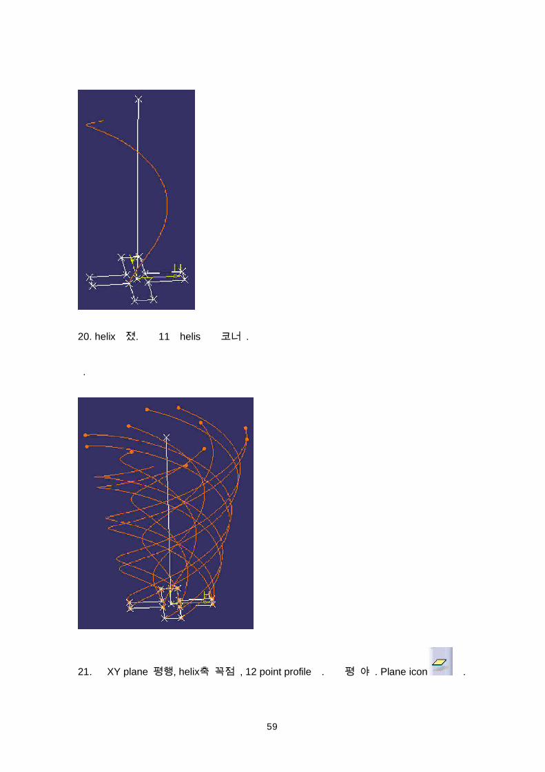
20. helix . 11 helis .
.
21. XY plane , helix , 12 point profile . . Plane icon .
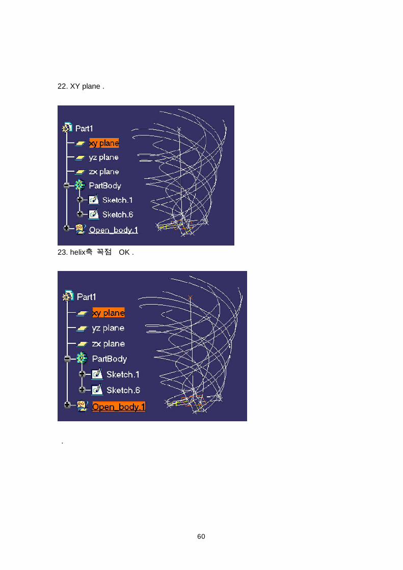
60
22. XY plane .
23. helix OK .
.
61
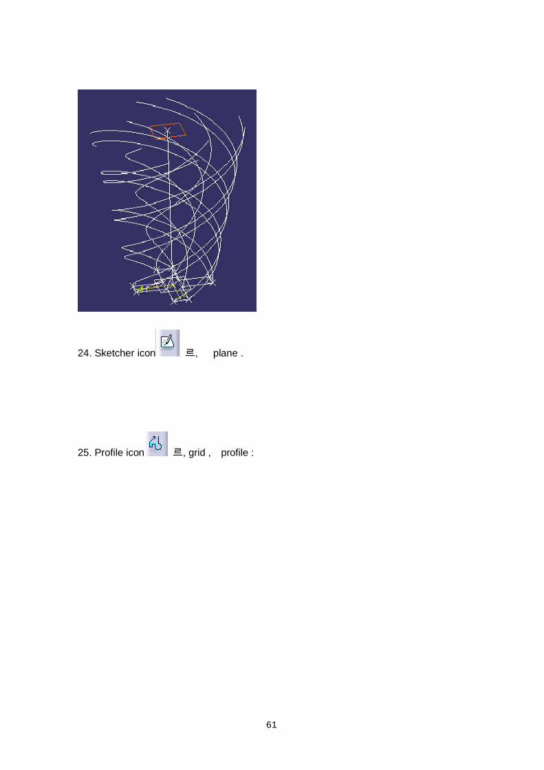
24. Sketcher icon , plane .
25. Profile icon , grid , profile :
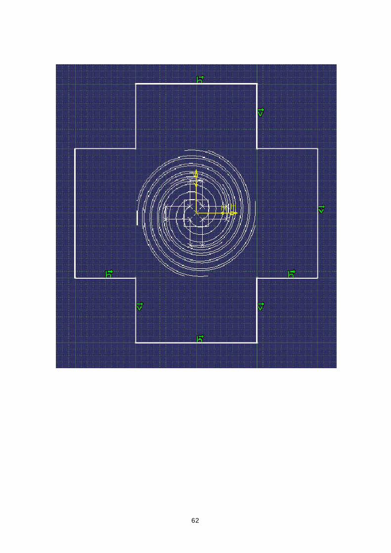
62
63
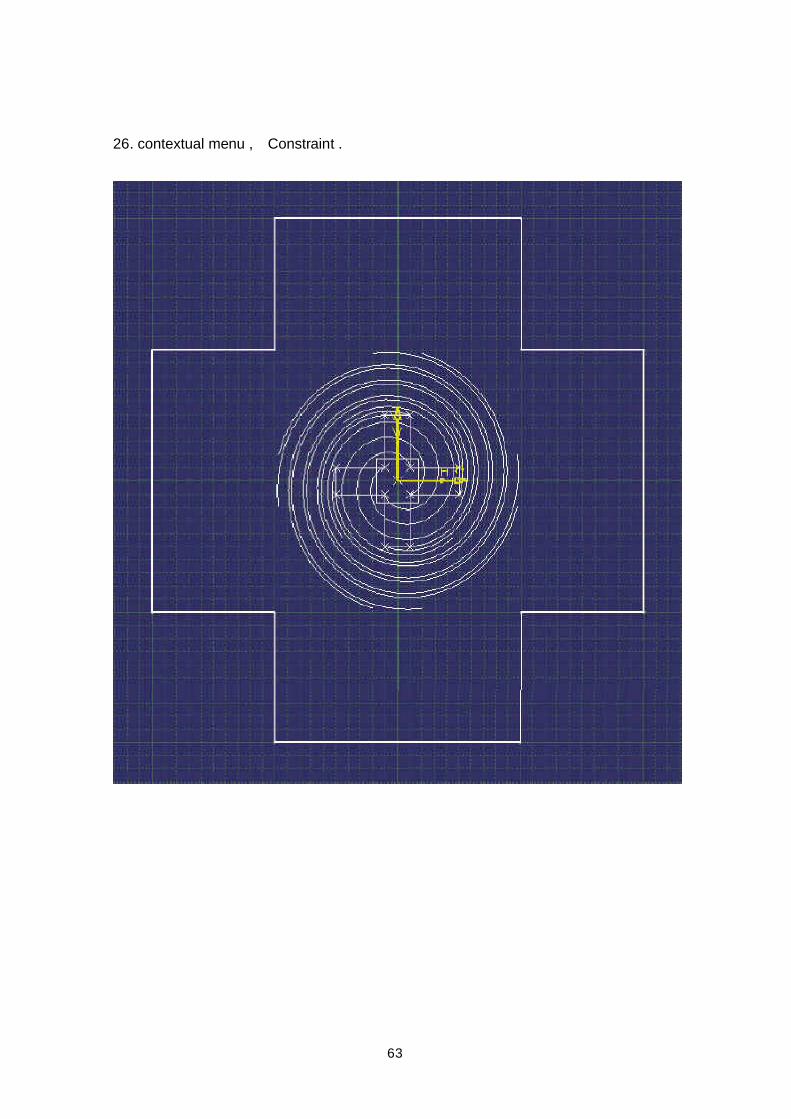
26. contextual menu , Constraint .
64
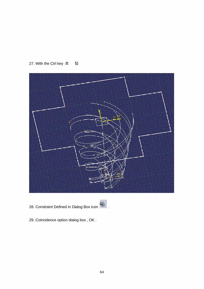
27. With the Ctrl key
28. Constraint Defined in Dialog Box icon .
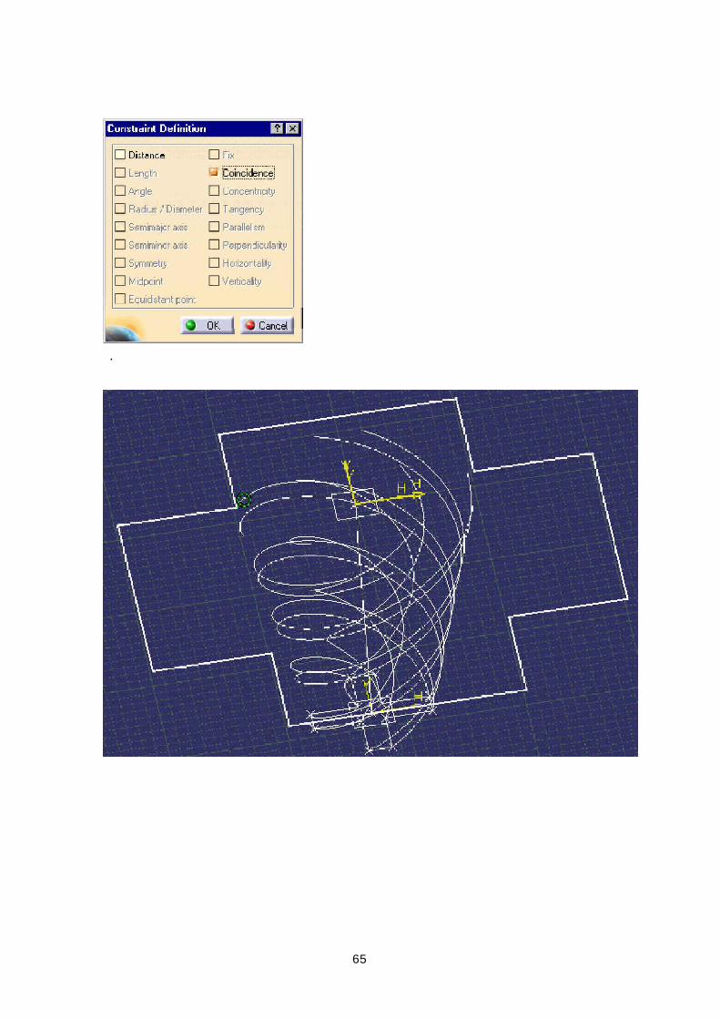
29. Coincidence option dialog box , OK .
65
.
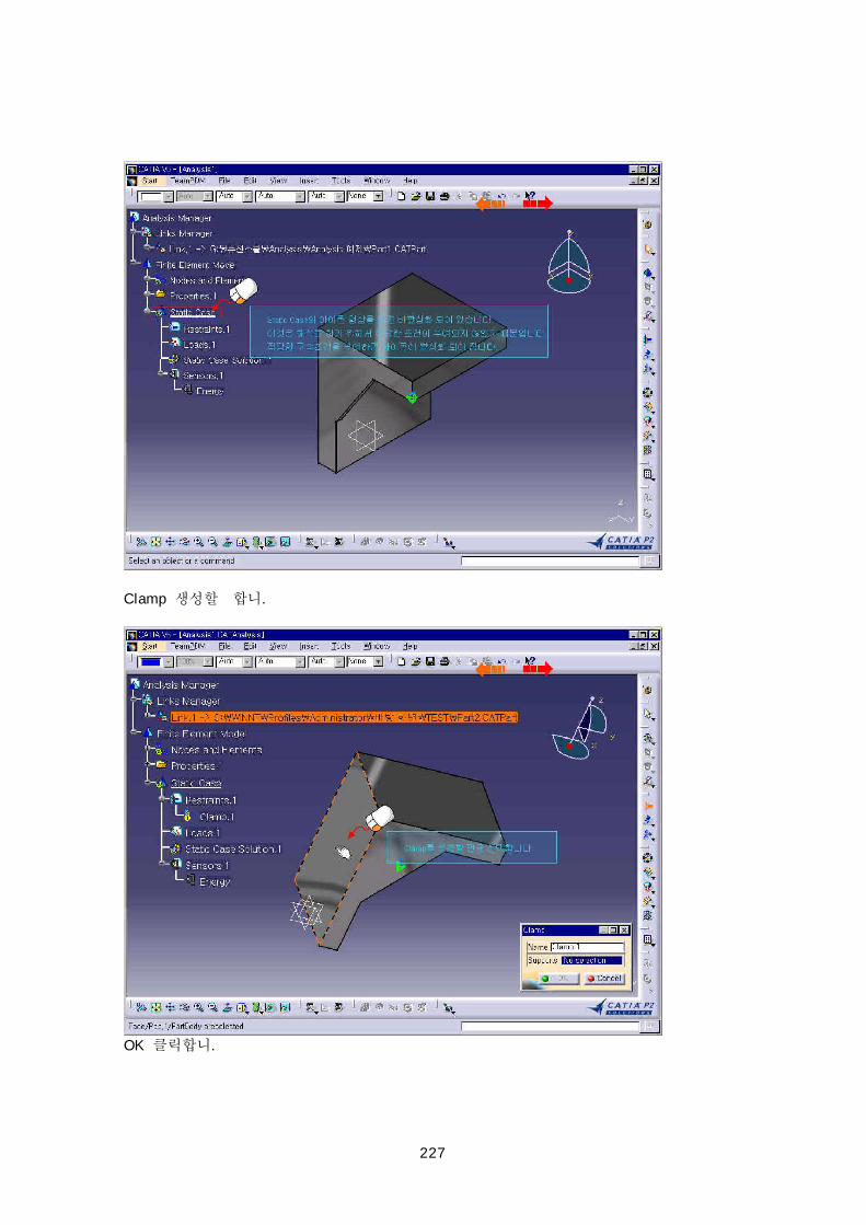
66
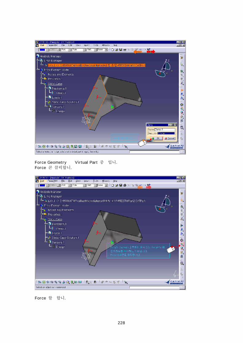
30. helix 11 coincidence .
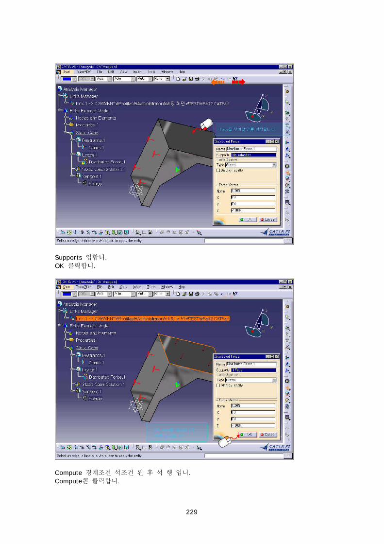
.
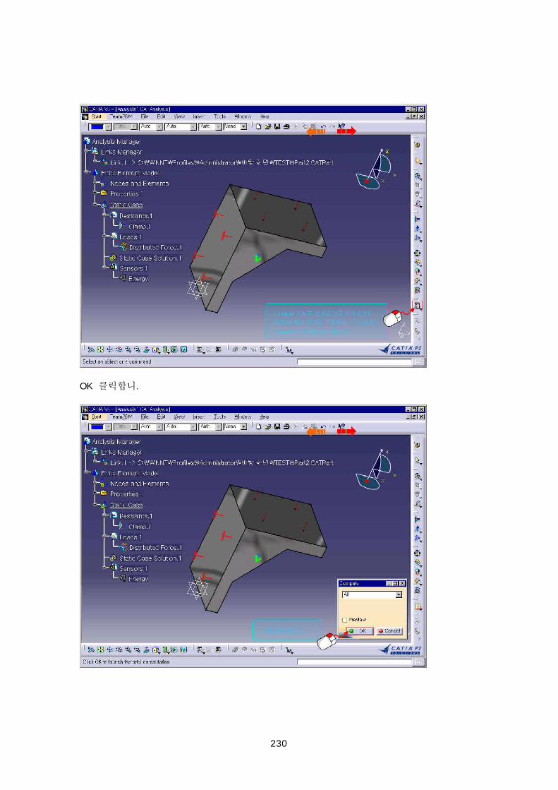
67
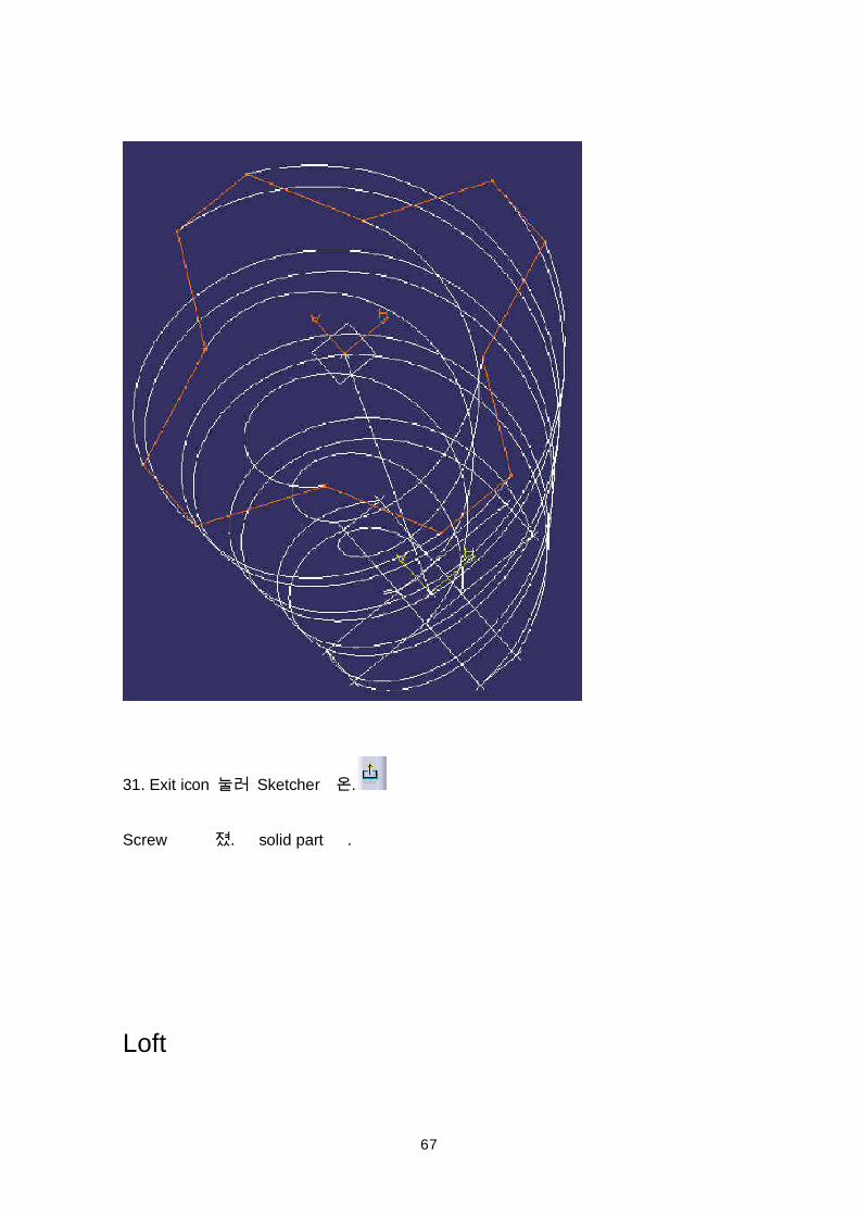
31. Exit icon Sketcher .
Screw . solid part .
Loft
68
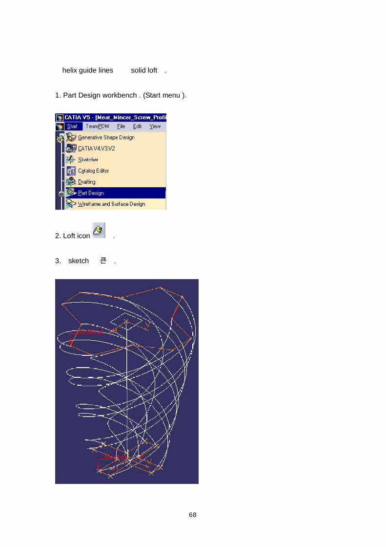
helix guide lines solid loft .
1. Part Design workbench . (Start menu ).
2. Loft icon .
3. sketch .
69
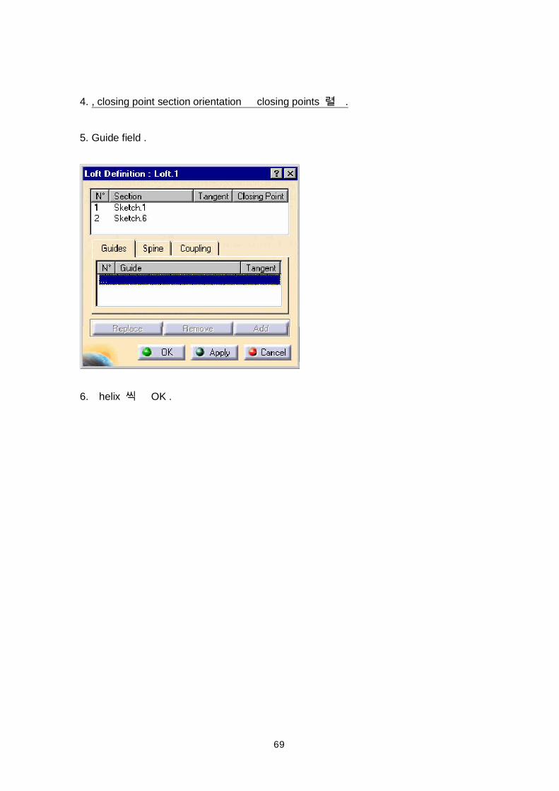
4. , closing point section orientation closing points .
5. Guide field .
6. helix OK .
70
.
71
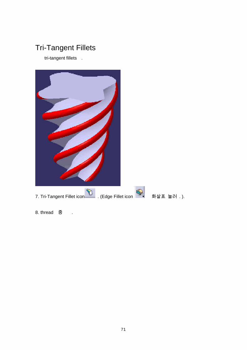
Tri-Tangent Fillets tri-tangent fillets .
7. Tri-Tangent Fillet icon . (Edge Fillet icon . ).
8. thread .
72
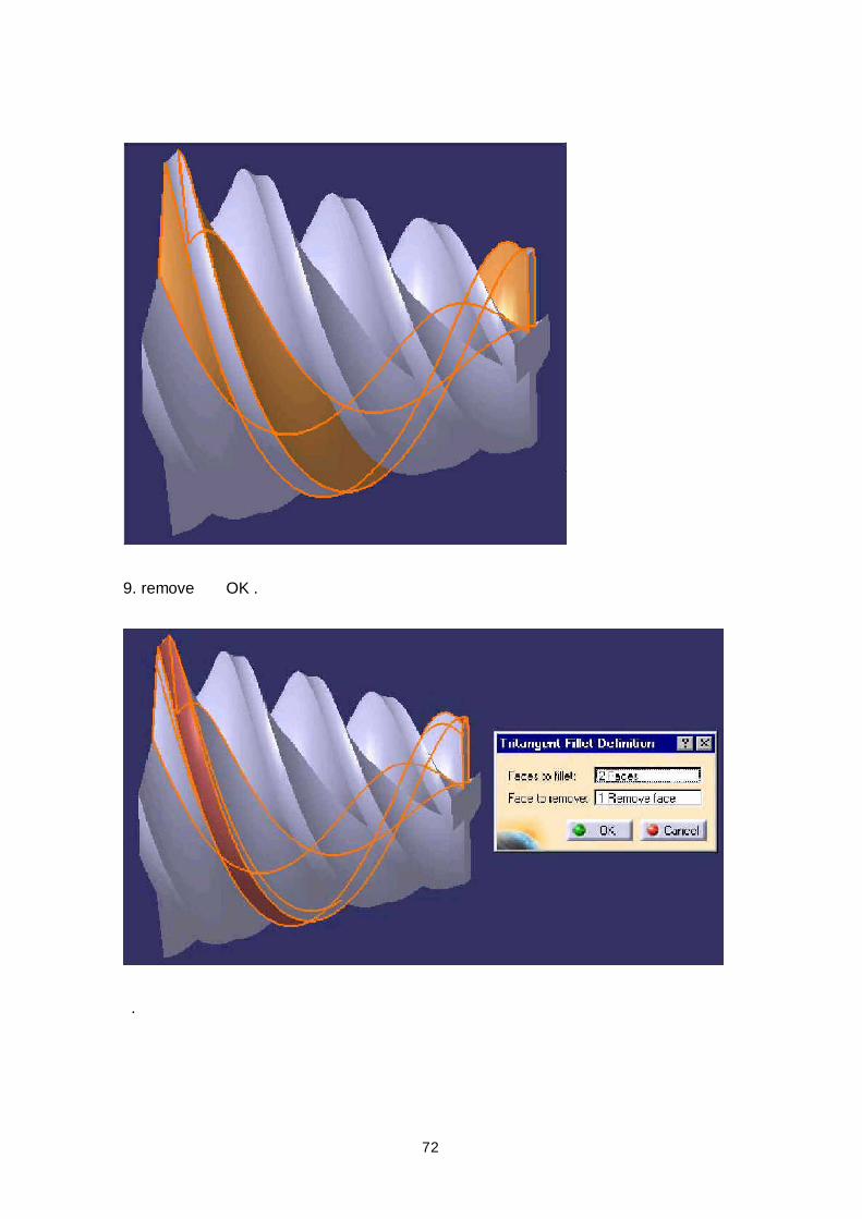
9. remove OK .
.
73
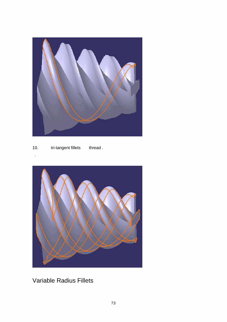
10. tri-tangent fillets thread . .
Variable Radius Fillets
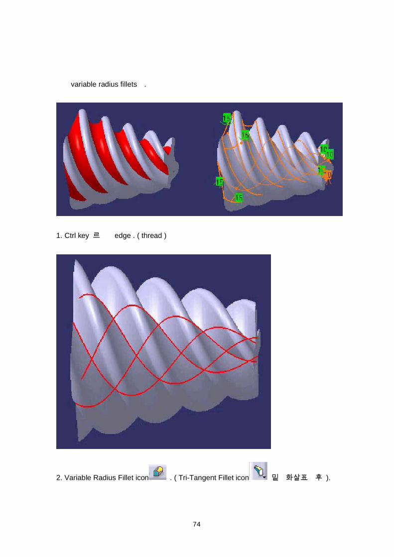
74
variable radius fillets .
1. Ctrl key edge . ( thread )
2. Variable Radius Fillet icon . ( Tri-Tangent Fillet icon ).
75
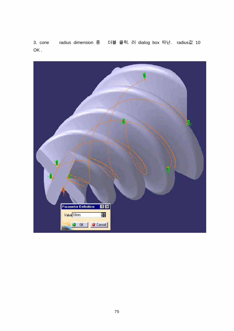
3. cone radius dimension . dialog box . radius 10OK .
76
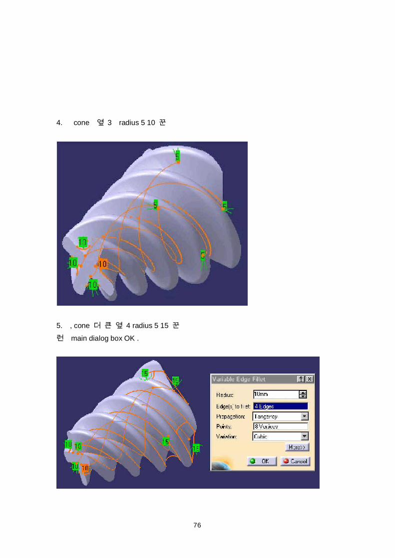
4. cone 3 radius 5 10
5. , cone 4 radius 5 15 main dialog box OK .
77
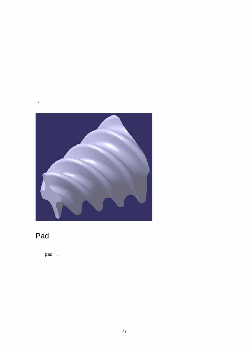
.
Pad
pad .
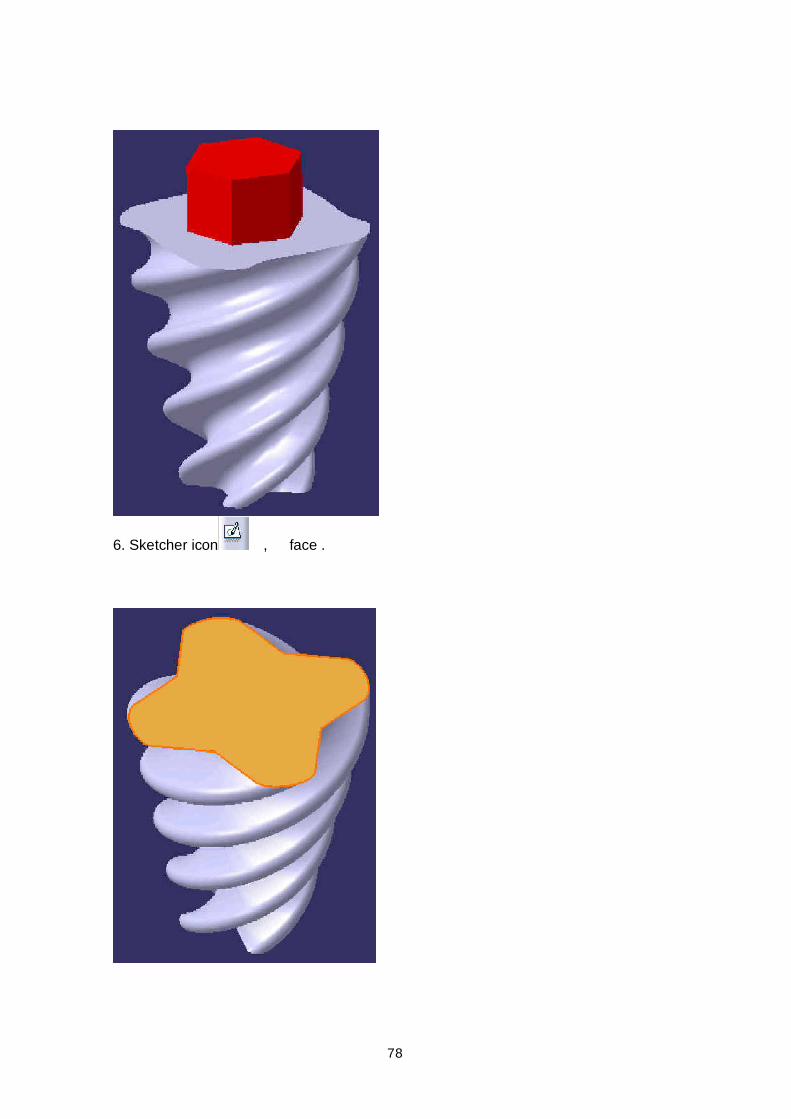
78
6. Sketcher icon , face .
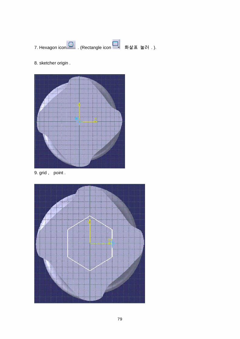
79
7. Hexagon icon . (Rectangle icon . ).
8. sketcher origin .
9. grid , point .
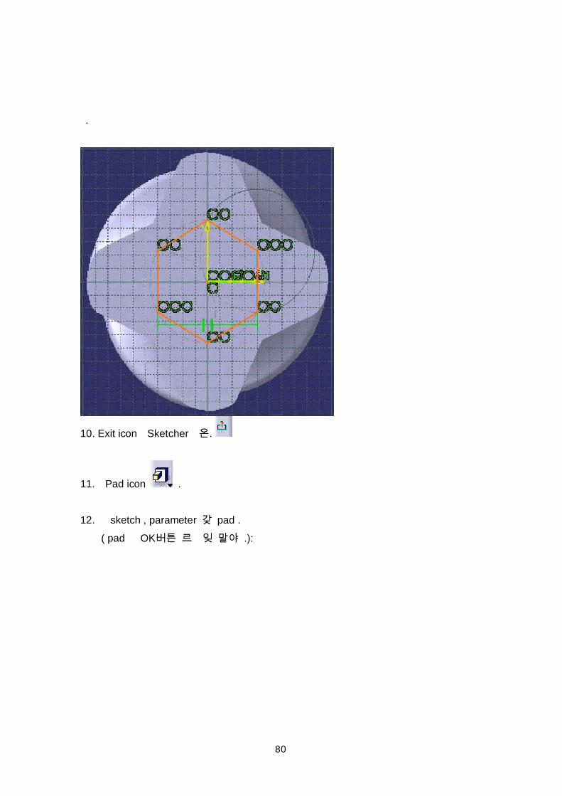
80
.
10. Exit icon Sketcher .
11. Pad icon .
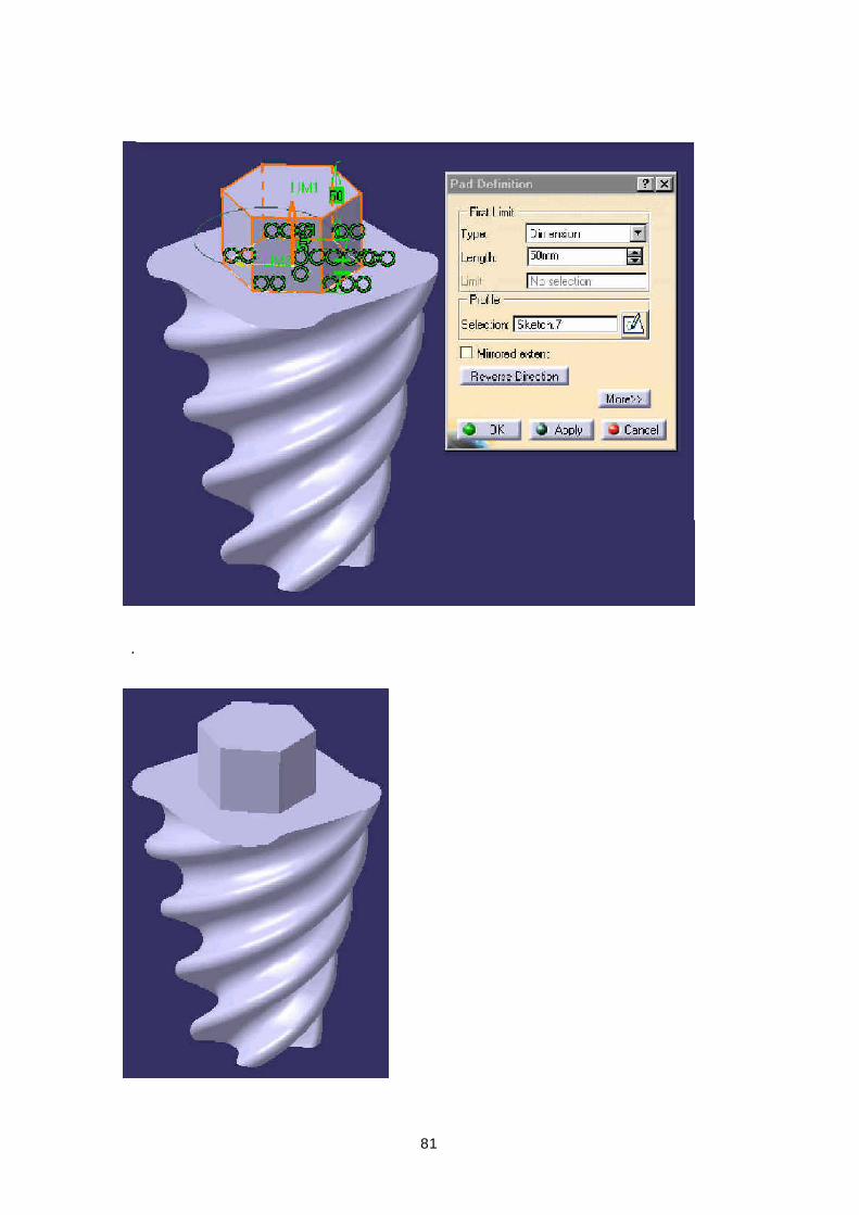
12. sketch , parameter pad .( pad OK .):
81
.
82
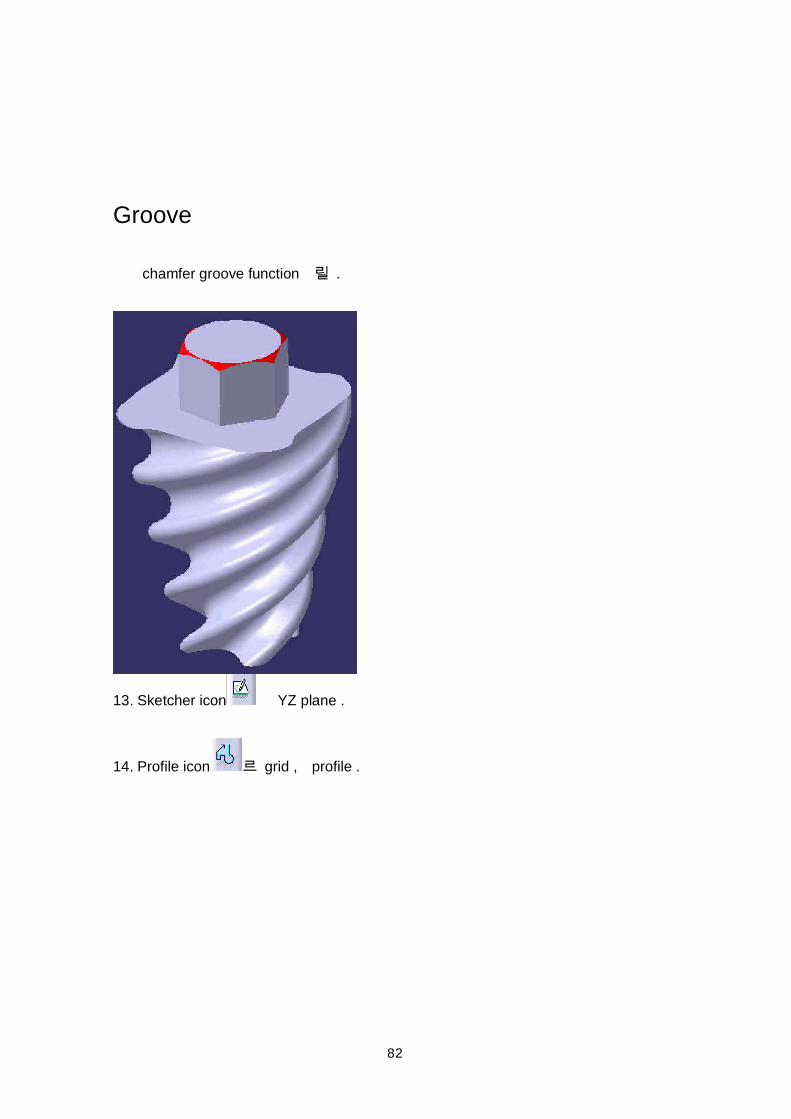
Groove
chamfer groove function .
13. Sketcher icon YZ plane .
14. Profile icon grid , profile .
83
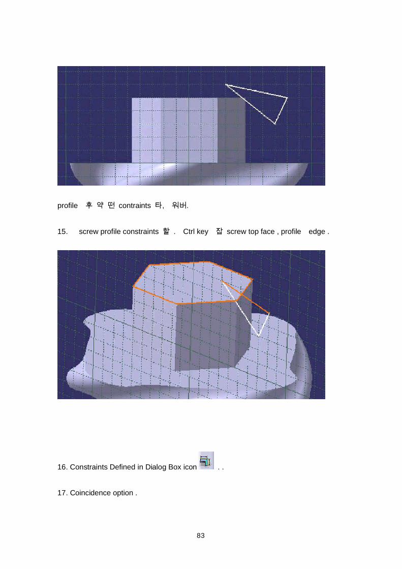
profile contraints , .
15. screw profile constraints . Ctrl key screw top face , profile edge .
16. Constraints Defined in Dialog Box icon . .
17. Coincidence option .
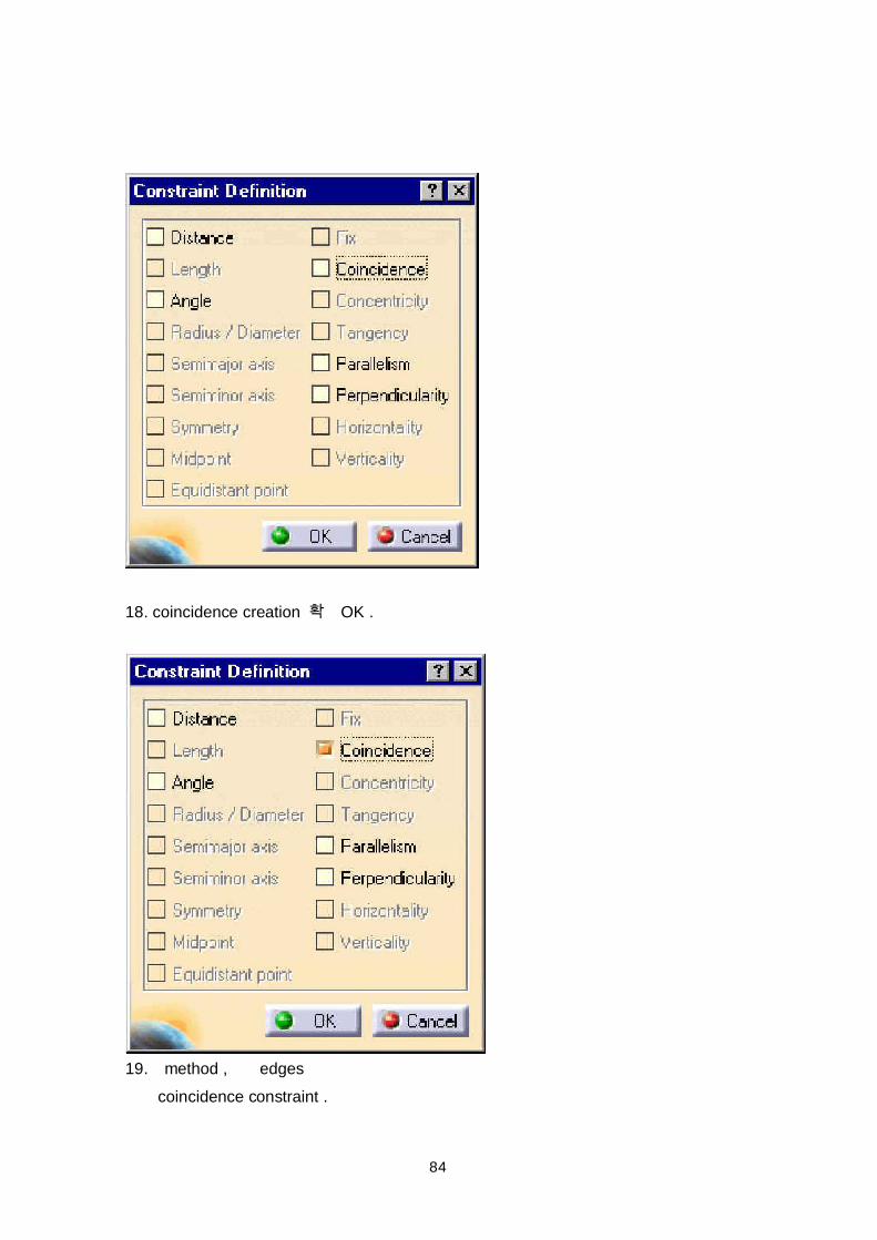
84
18. coincidence creation OK .
19. method , edgescoincidence constraint .
85
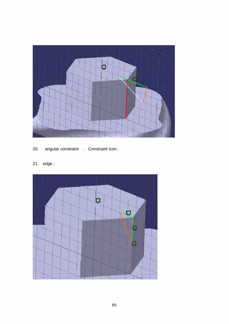
20. angular constraint . Constraint icon .
21. edge :
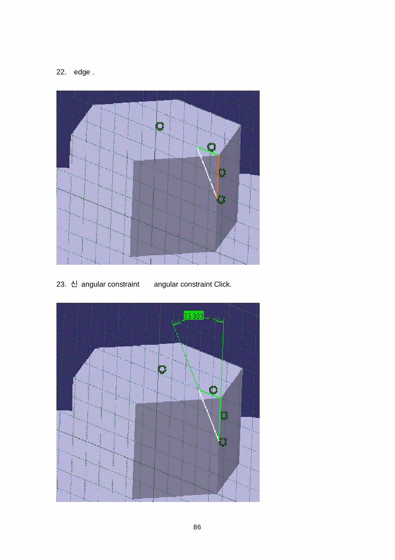
86
22. edge .
23. angular constraint angular constraint Click.
87
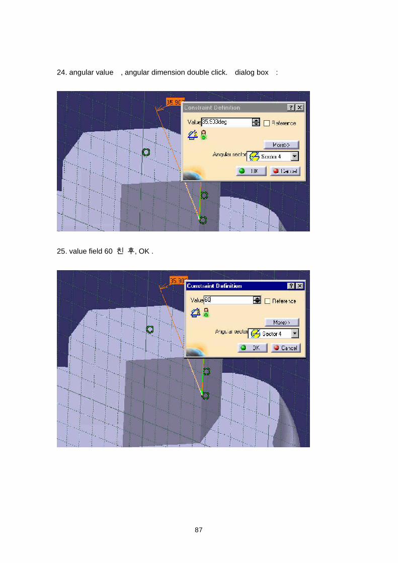
24. angular value , angular dimension double click. dialog box :
25. value field 60 , OK .
88
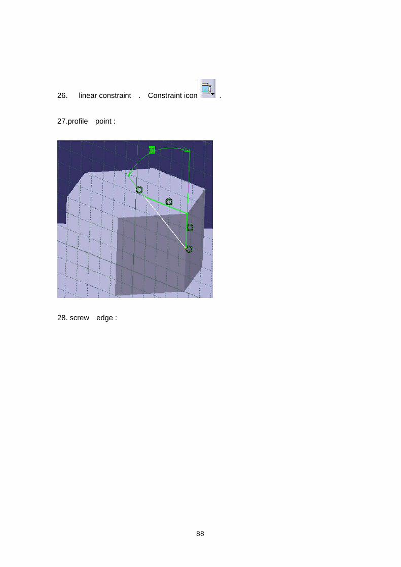
26. linear constraint . Constraint icon .
27.profile point :
28. screw edge :
89
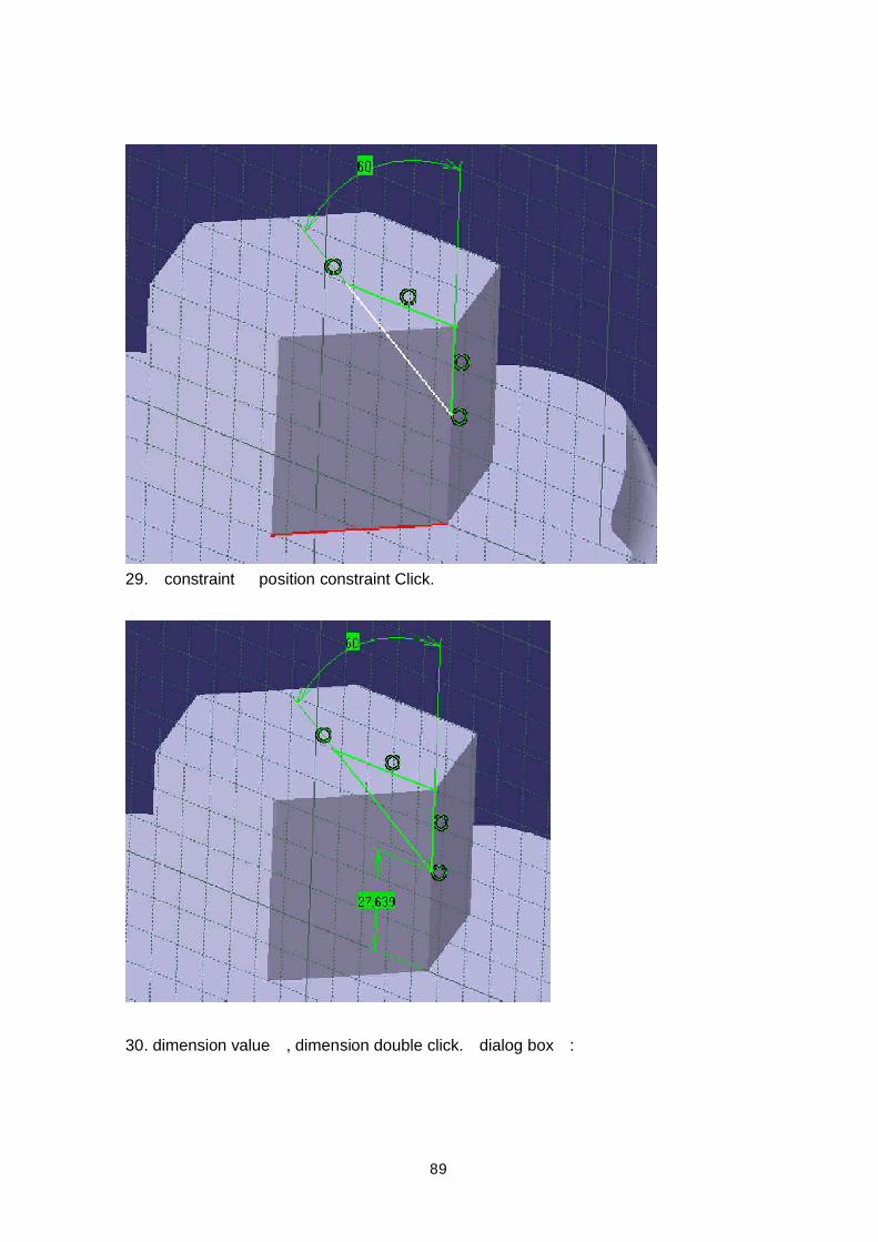
29. constraint position constraint Click.
30. dimension value , dimension double click. dialog box :
90
31. value field 46 , OK .
32. groove ,axis , Axis icon .
91
33. grid , axis :
34. Exit icon Sketcher .
35. , groove Groove icon , , sketch .
36. groove parameters OK .
92
:
Pad
pad :
93
37. Sketcher icon , face :
38. Circle icon .
94
39. circle center, origin
40. grid , circle radius point .
41. Exit icon Sketcher .
42. , Pad icon .
43. sketch , parameter pad .( pad OK .):
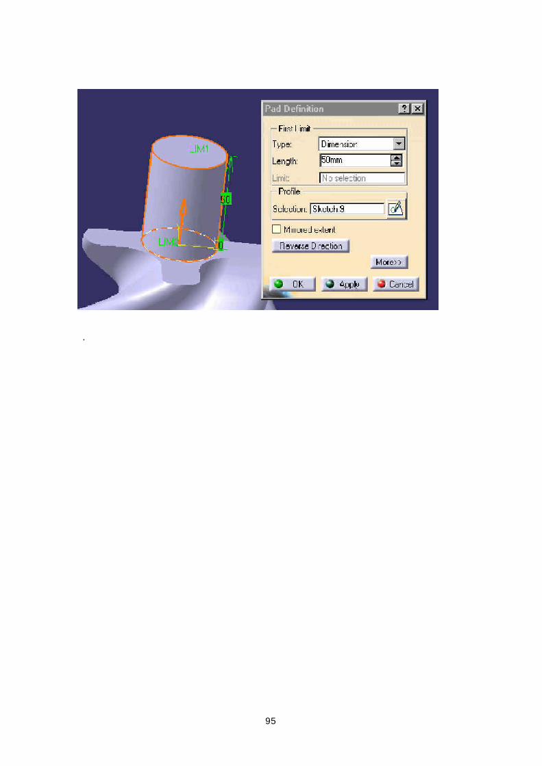
95
.
96
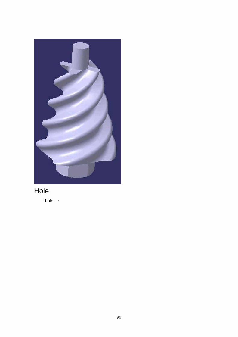
Hole hole :
97
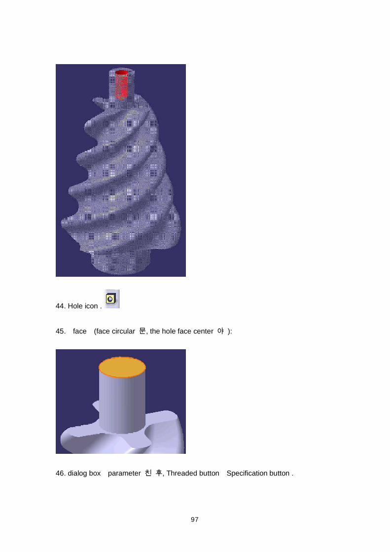
44. Hole icon .
45. face (face circular , the hole face center ):
46. dialog box parameter , Threaded button Specification button .
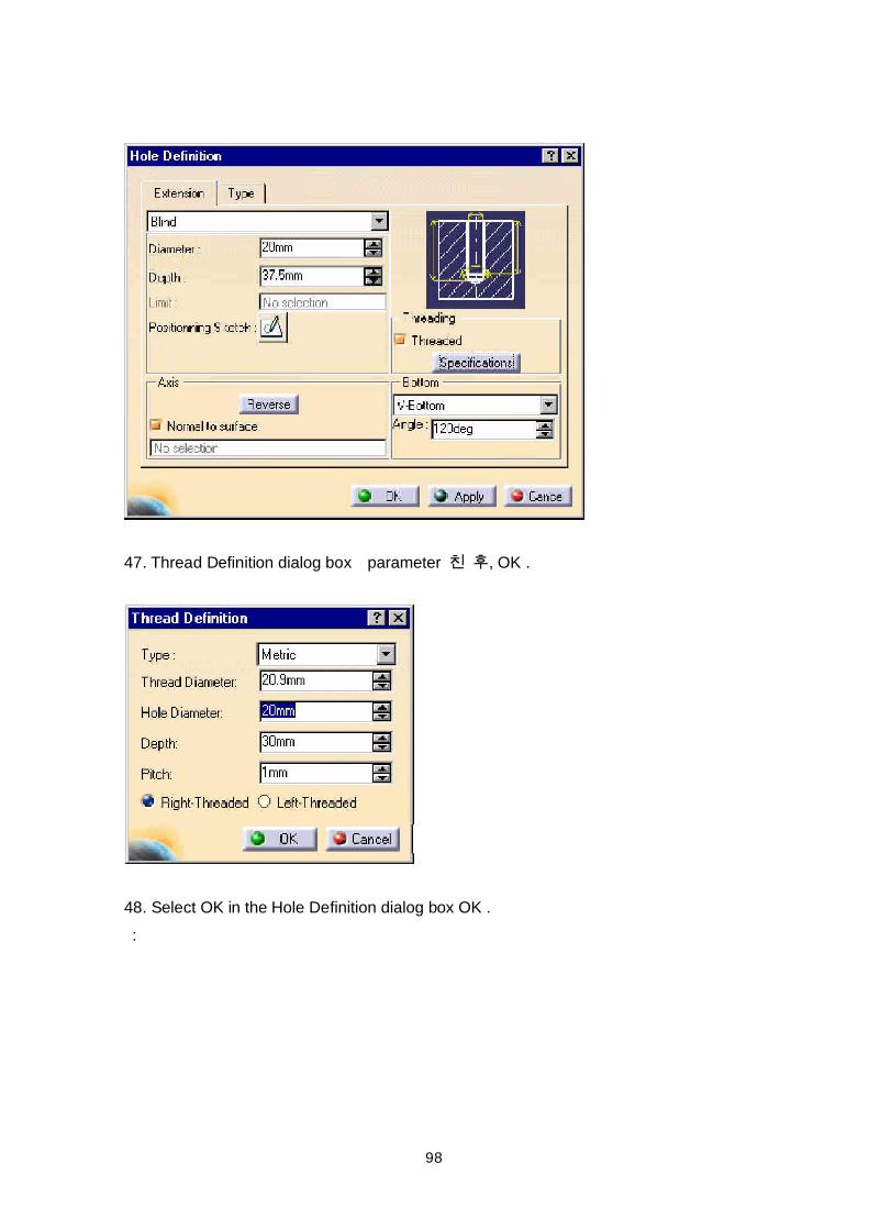
98
47. Thread Definition dialog box parameter , OK .
48. Select OK in the Hole Definition dialog box OK . :
99
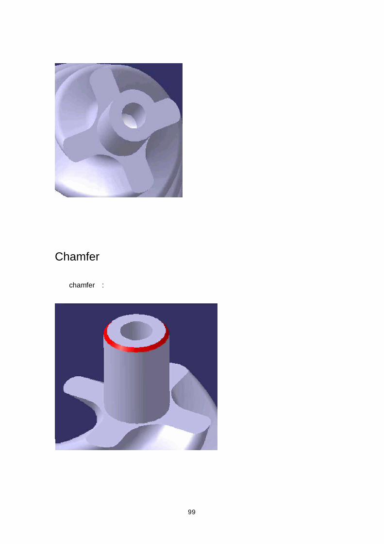
Chamfer
chamfer :
100
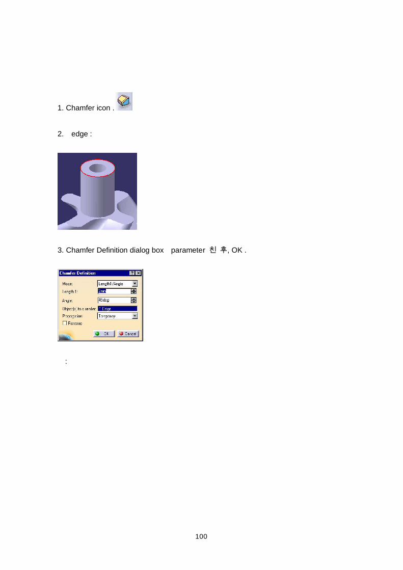
1. Chamfer icon .
2. edge :
3. Chamfer Definition dialog box parameter , OK .
:
101
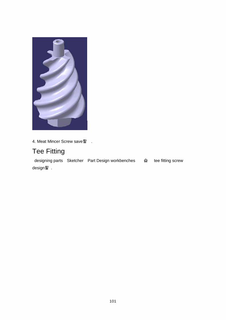
4. Meat Mincer Screw save .
Tee Fitting designing parts Sketcher Part Design workbenches tee fitting screwdesign .
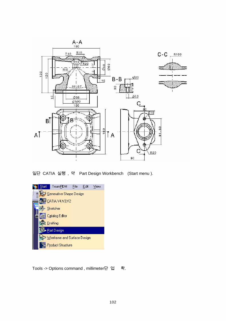
102
CATIA , Part Design Workbench (Start menu ).
Tools -> Options command , millimeter .
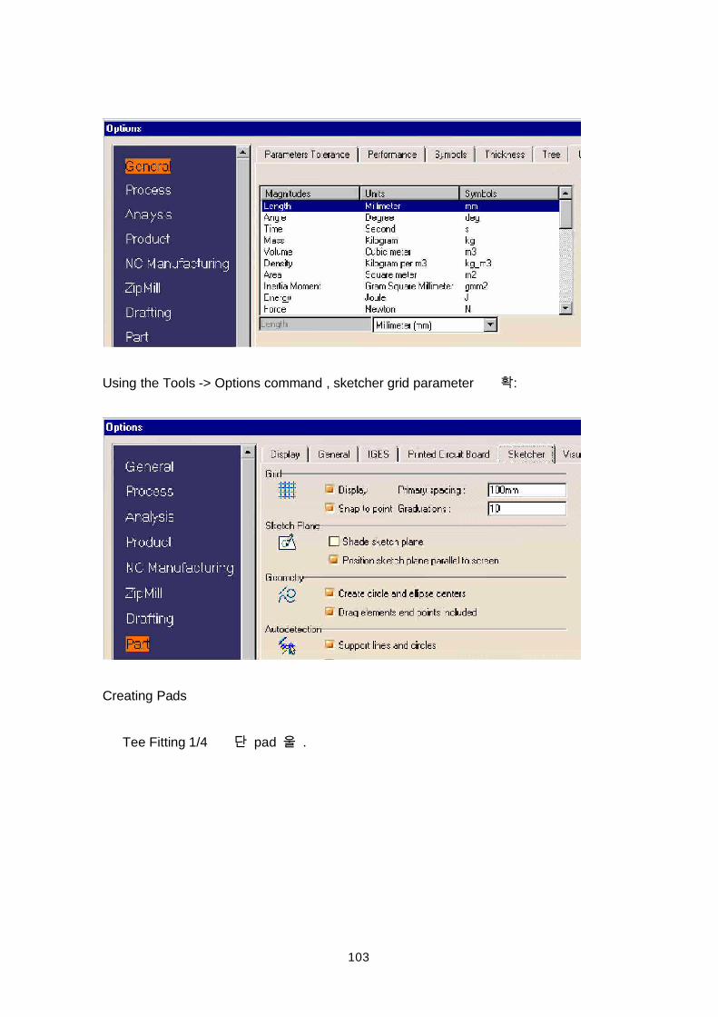
103
Using the Tools -> Options command , sketcher grid parameter :
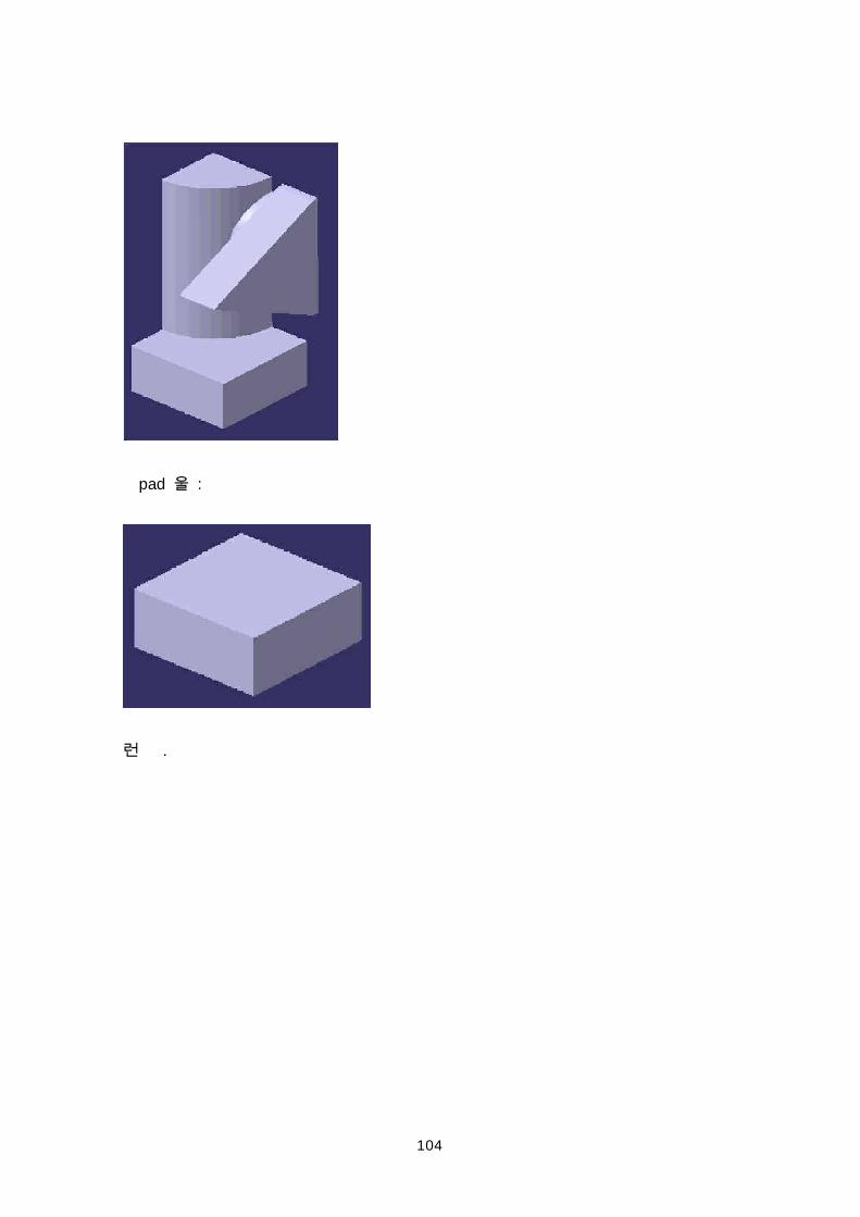
Creating Pads
Tee Fitting 1/4 pad .
104
pad :
.
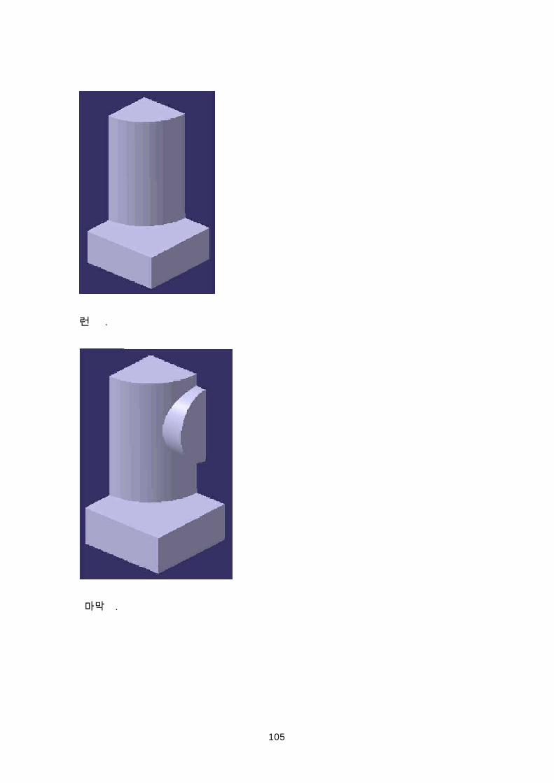
105
.
.
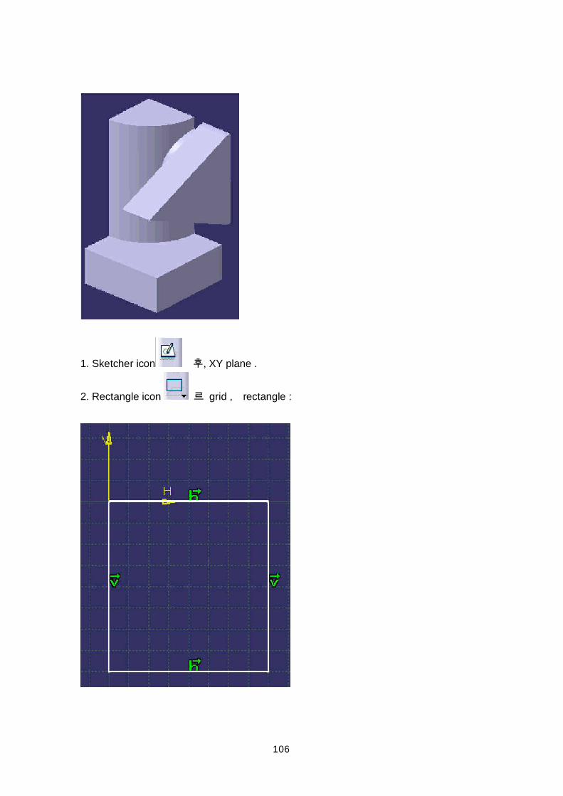
106
1. Sketcher icon , XY plane .
2. Rectangle icon grid , rectangle :
107
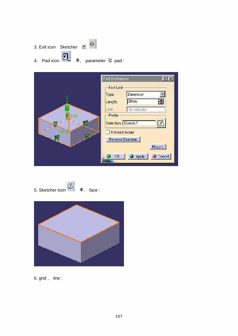
3. Exit icon Sketcher .
4. Pad icon , parameter pad :
5. Sketcher icon , face :
6. grid , line :
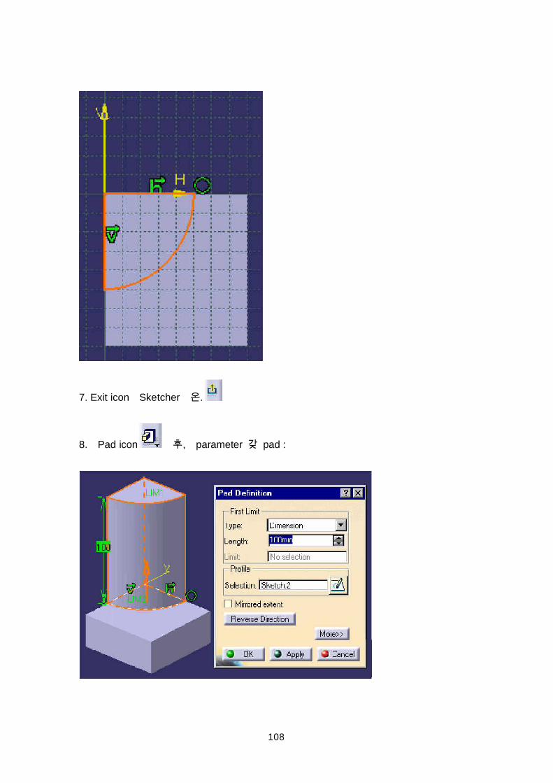
108
7. Exit icon Sketcher .
8. Pad icon , parameter pad :
109
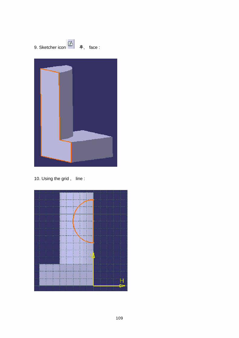
9. Sketcher icon , face :
10. Using the grid , line :
110
11. Exit icon Sketcher .
12. Pad icon , parameter pad :
13. Sketcher icon , face :
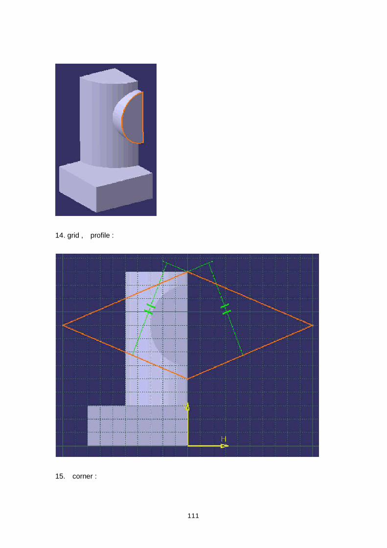
111
14. grid , profile :
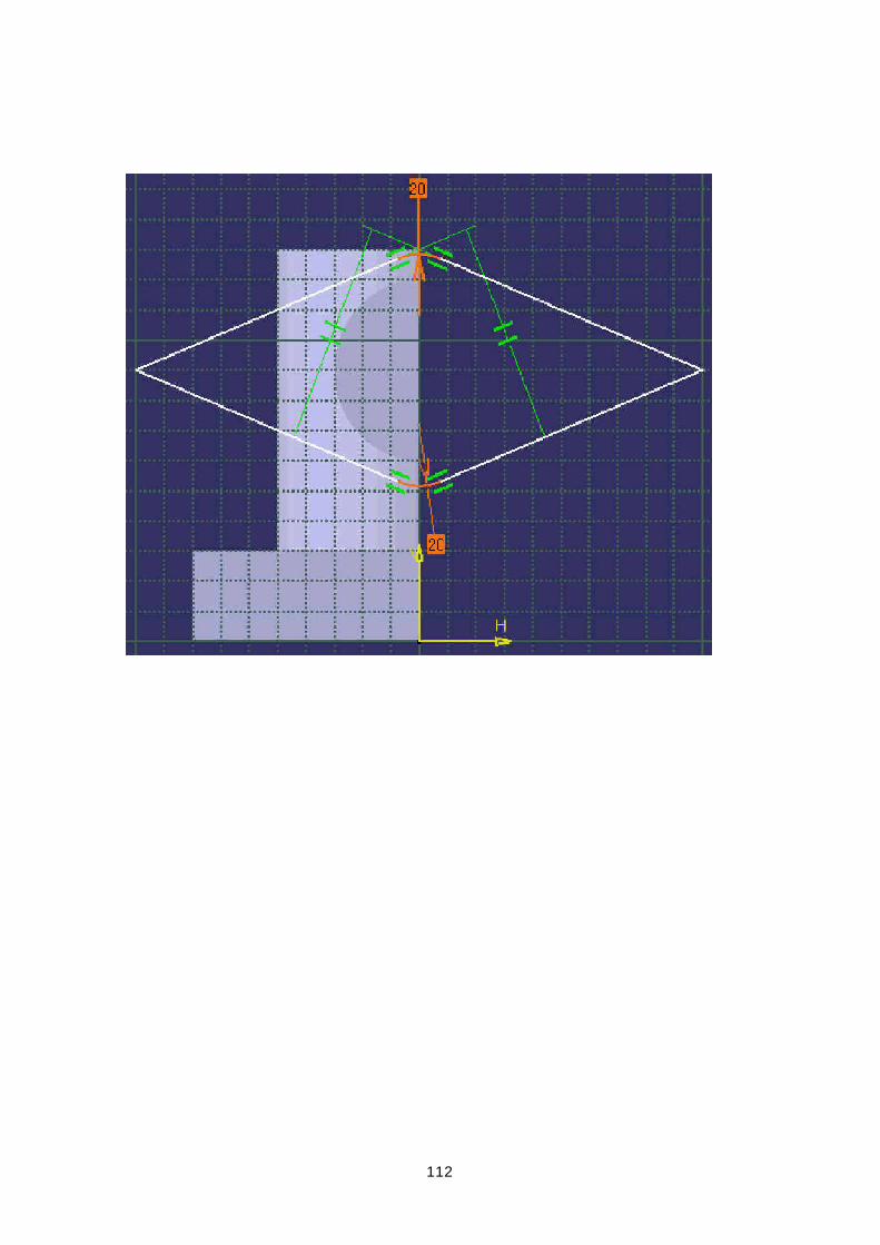
15. corner :
112
113
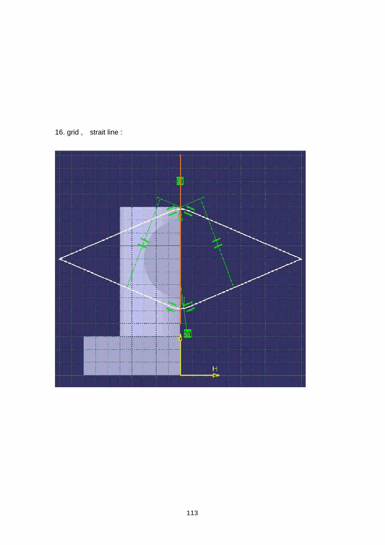
16. grid , strait line :
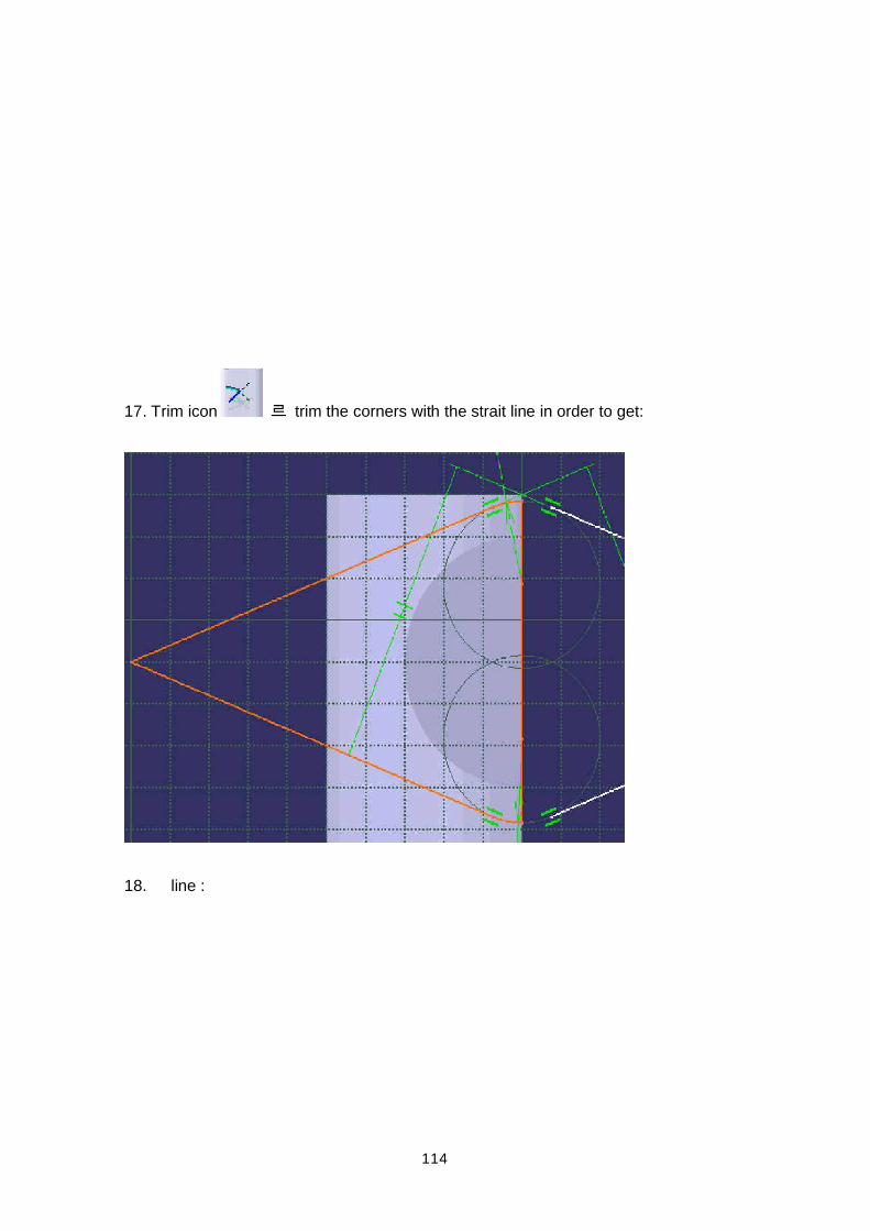
114
17. Trim icon trim the corners with the strait line in order to get:
18. line :
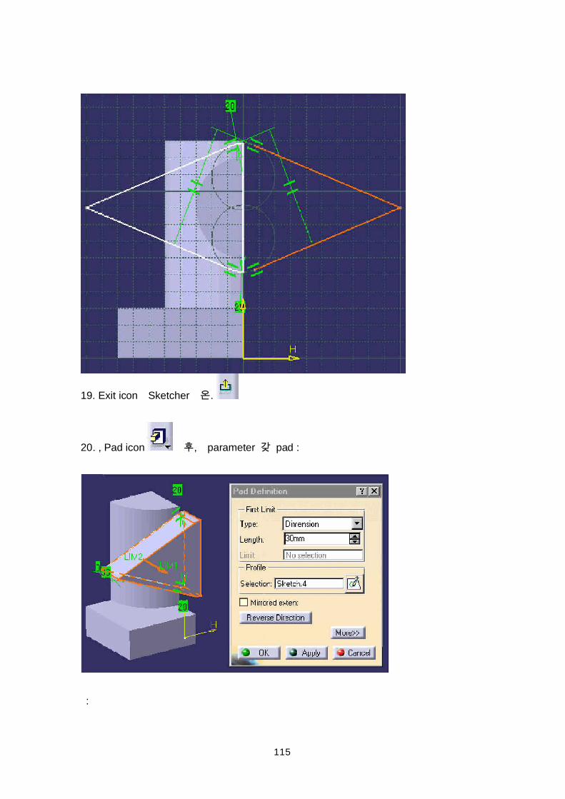
115
19. Exit icon Sketcher .
20. , Pad icon , parameter pad :
:
116
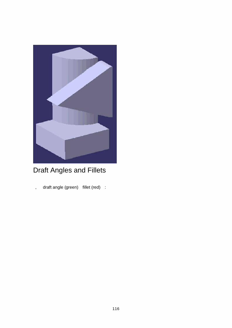
Draft Angles and Fillets
, draft angle (green) fillet (red) :
117
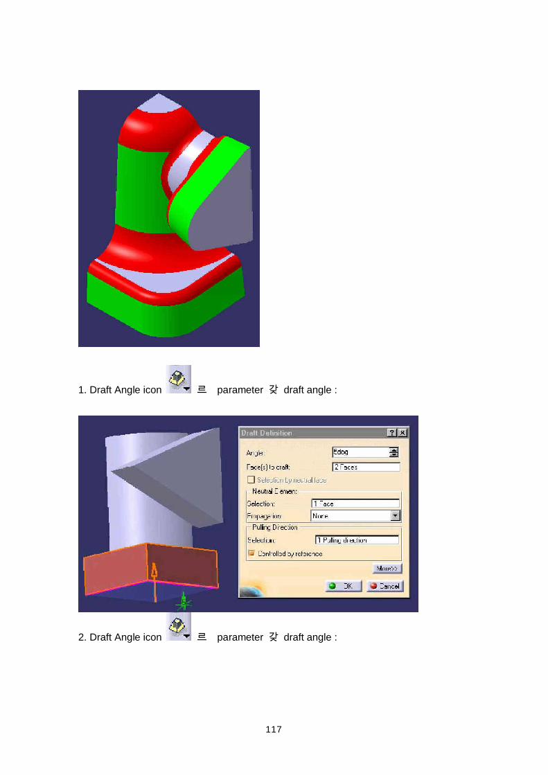
1. Draft Angle icon parameter draft angle :
2. Draft Angle icon parameter draft angle :
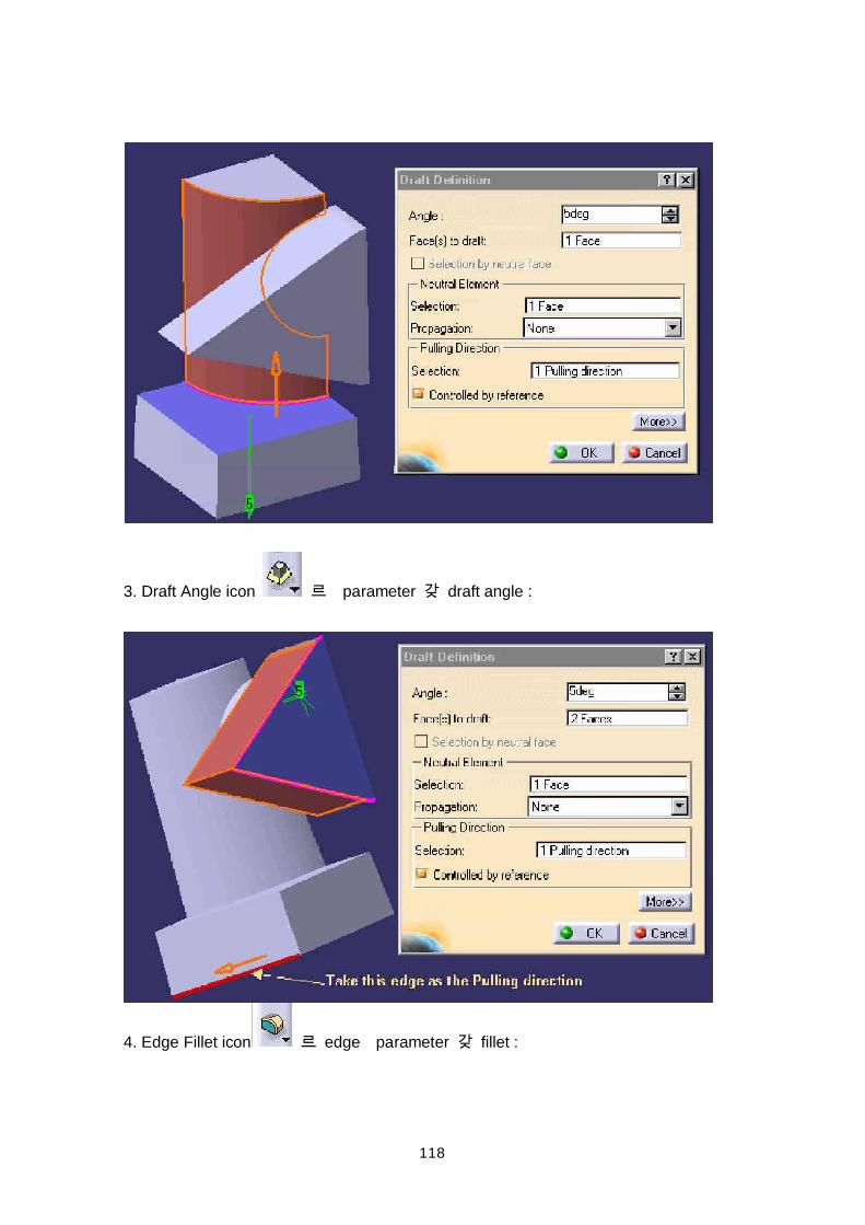
118
3. Draft Angle icon parameter draft angle :
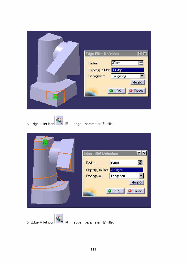
4. Edge Fillet icon edge parameter fillet :
119
5. Edge Fillet icon edge parameter fillet :
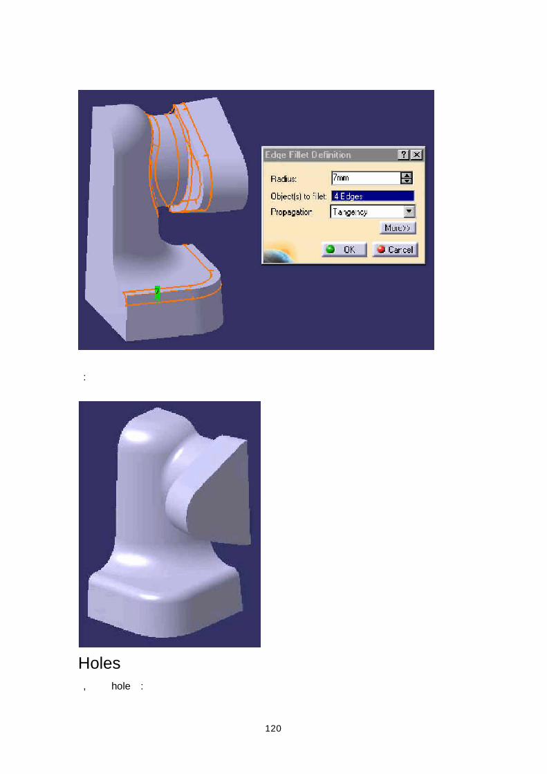
6. Edge Fillet icon edge parameter fillet :
120
:
Holes , hole :
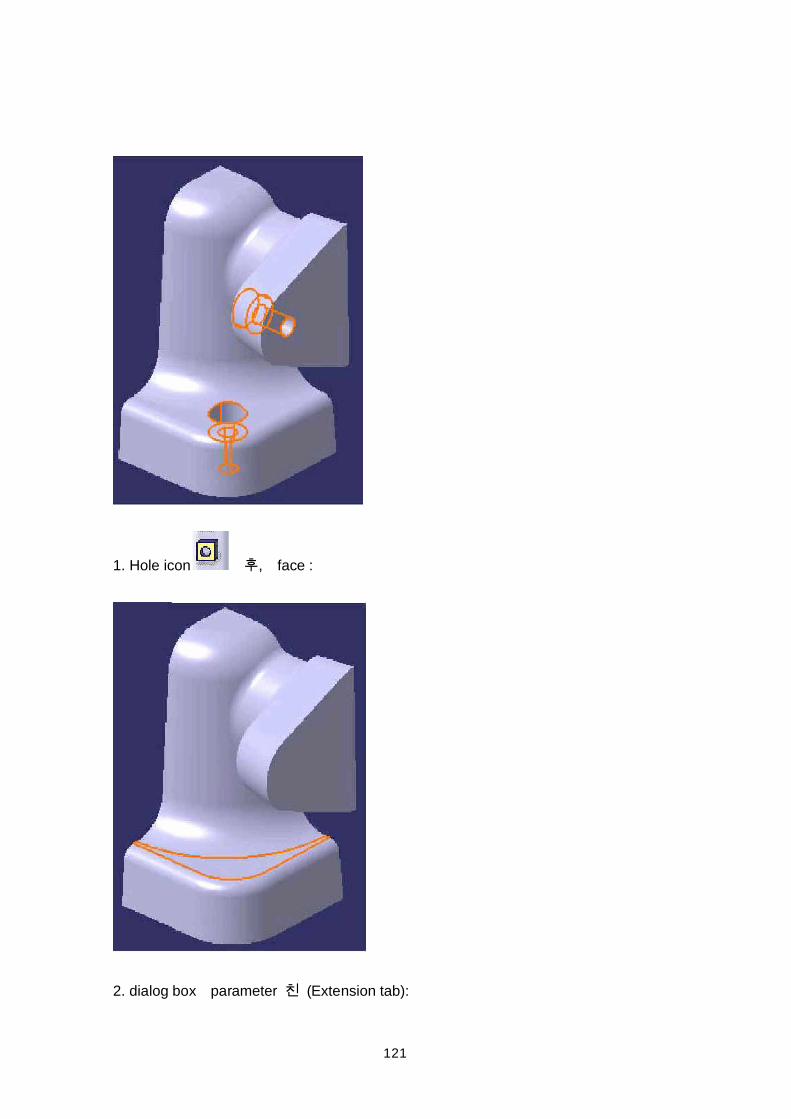
121
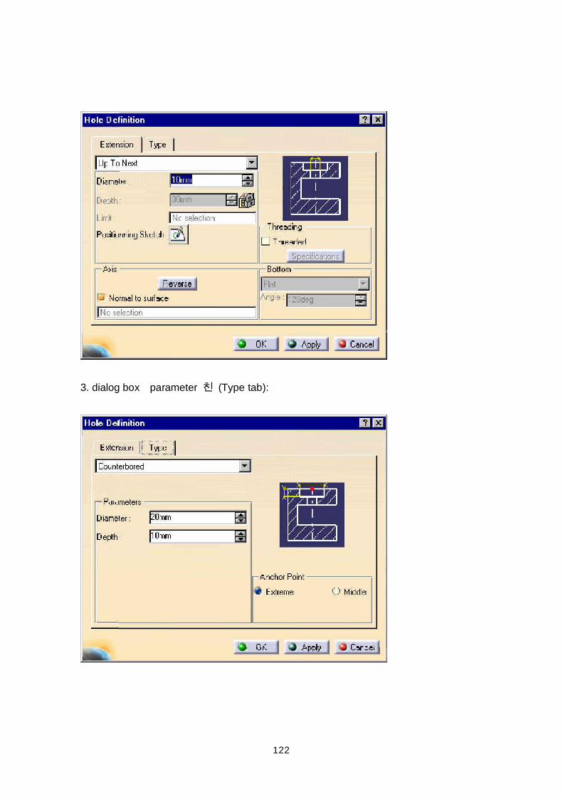
1. Hole icon , face :
2. dialog box parameter (Extension tab):
122
3. dialog box parameter (Type tab):
123
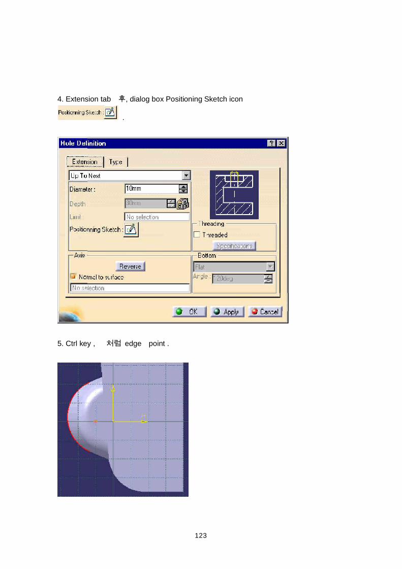
4. Extension tab , dialog box Positioning Sketch icon
.
5. Ctrl key , edge point .
124
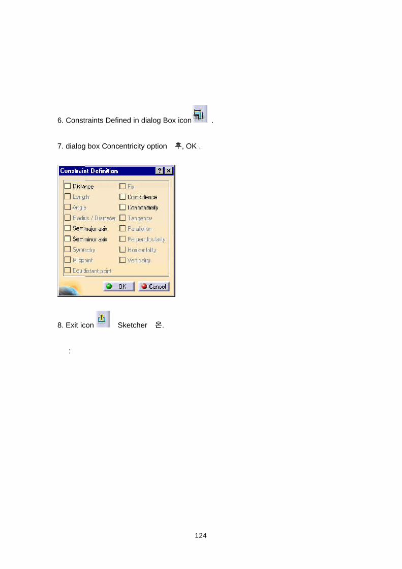
6. Constraints Defined in dialog Box icon .
7. dialog box Concentricity option , OK .
8. Exit icon Sketcher .
:
125
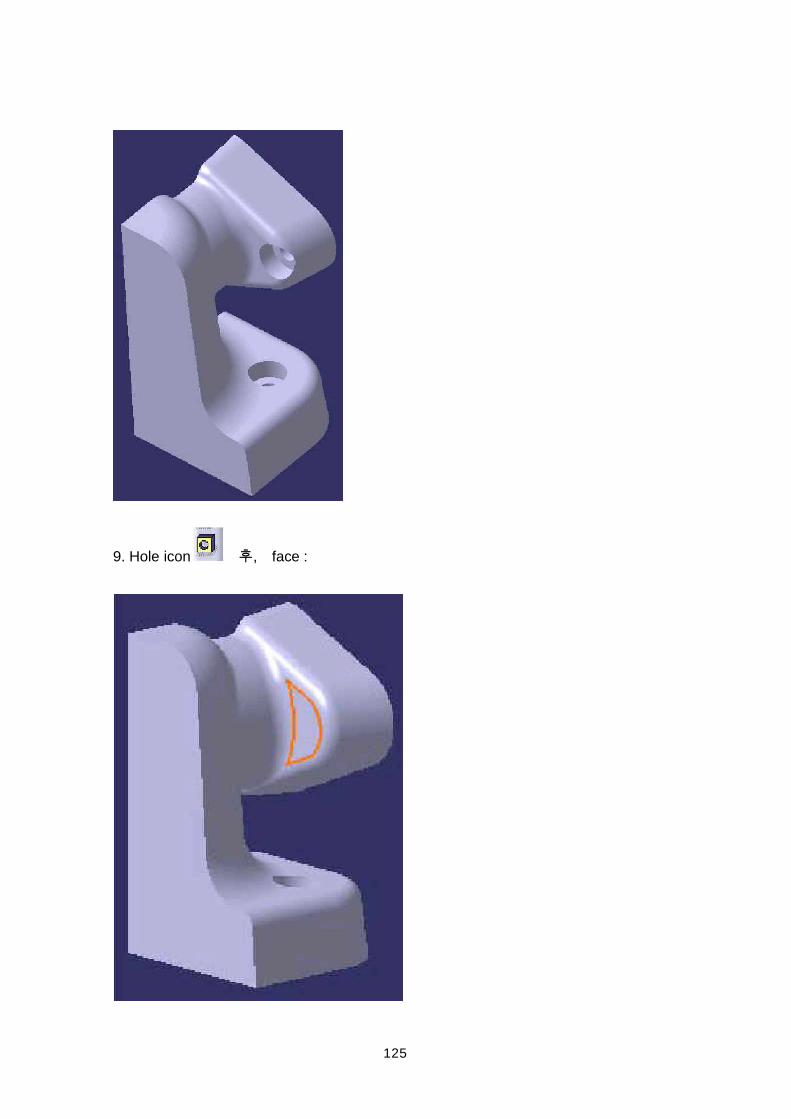
9. Hole icon , face :
126
10. dialog box parameter (Extension tab):
11. dialog box parameter (Type tab):
12. Extension tab , dialog box Positioning Sketch icon .
127
13. Ctrl key , edge point .
128
14. Constraints Defined in dialog Box icon .
15. dialog box Concentricity option , OK .
16. Exit icon Sketcher .
17. :
129
130
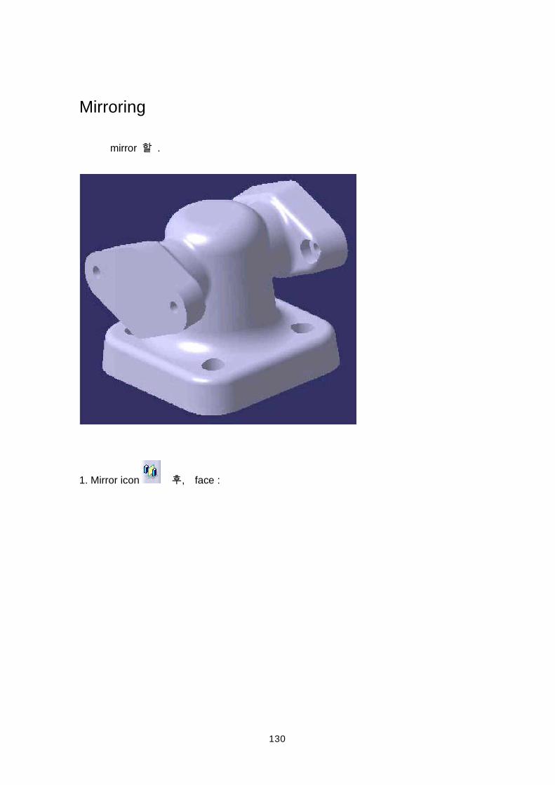
Mirroring
mirror .
1. Mirror icon , face :
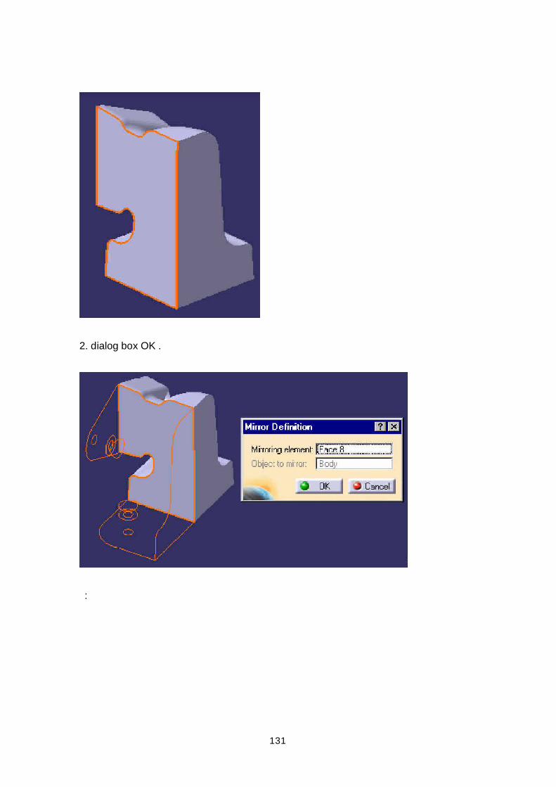
131
2. dialog box OK .
:
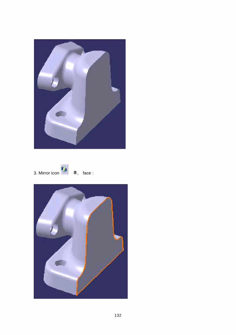
132
3. Mirror icon , face :
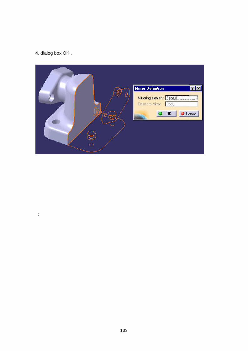
133
4. dialog box OK .
:
134
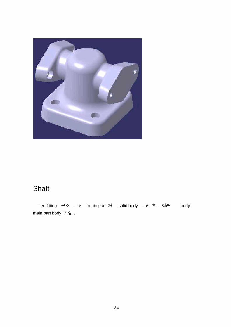
Shaft
tee fitting . main part solid body . , bodymain part body .
135
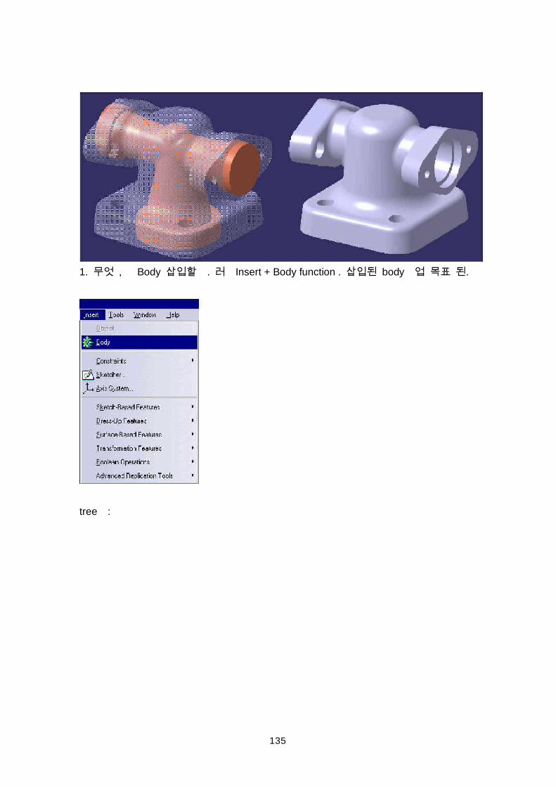
1. , Body . Insert + Body function . body .
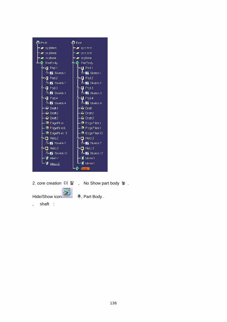
tree :
136
2. core creation , No Show part body .
Hide/Show icon , Part Body ., shaft :
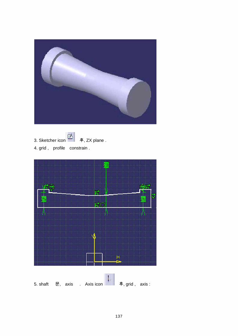
137
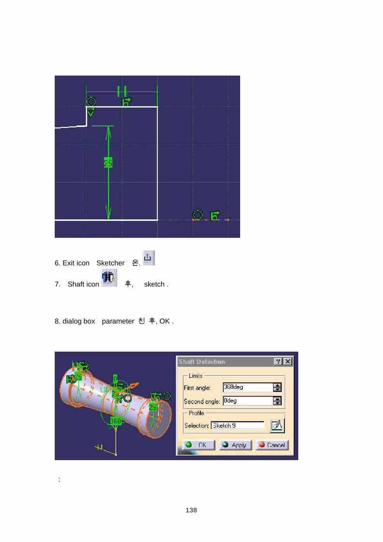
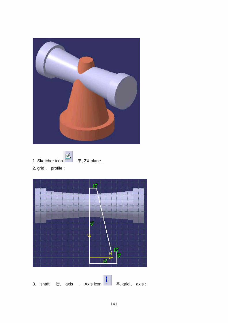
3. Sketcher icon , ZX plane .4. grid , profile constrain .
5. shaft , axis . Axis icon , grid , axis :
138
6. Exit icon Sketcher .
7. Shaft icon , sketch .
8. dialog box parameter , OK .
:
139
Fillet
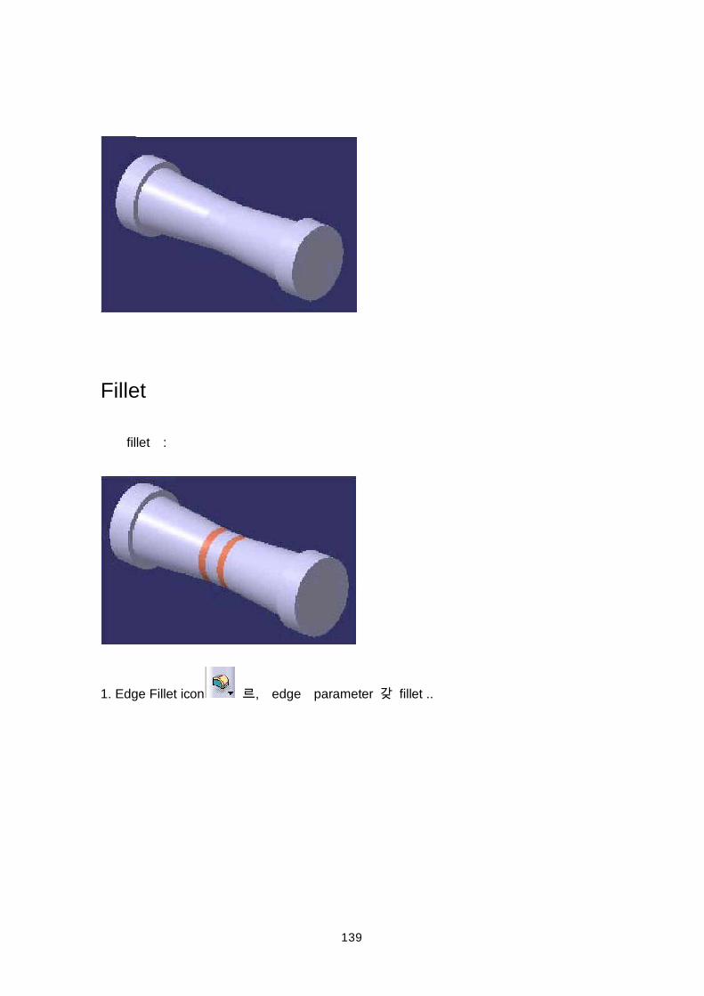
fillet :
1. Edge Fillet icon , edge parameter fillet ..
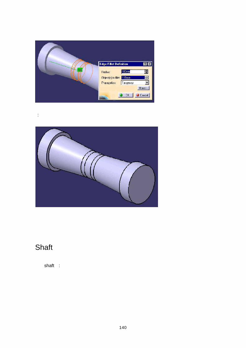
140
:
Shaft
shaft :
141
1. Sketcher icon , ZX plane .2. grid , profile :
3. shaft , axis . Axis icon , grid , axis :
142
4. Exit icon Sketcher .
5. Shaft icon , sketch .
6. dialog box parameter , OK .
143
:
Fillet
fillet :
144
1. Edge Fillet icon , edge parameter fillet ..:
:
145
146
Body
main part core .
1. Show part body . Hide/Show icon treePartBody .
2. core body cursor (tree) , contextual menu Body.2 object +Remove function(MB3).
147
:
148
Tee Fitting save .
CATIA V5 Assembly Design
Assembly Design Part (Top-Down) (Bottom-Up) .
(Concurrent Engineering) , . . Analysis , Bill of Material . CATIA V5
Part Design, Generative Drafting, DMU Navigator
Version 4Data .
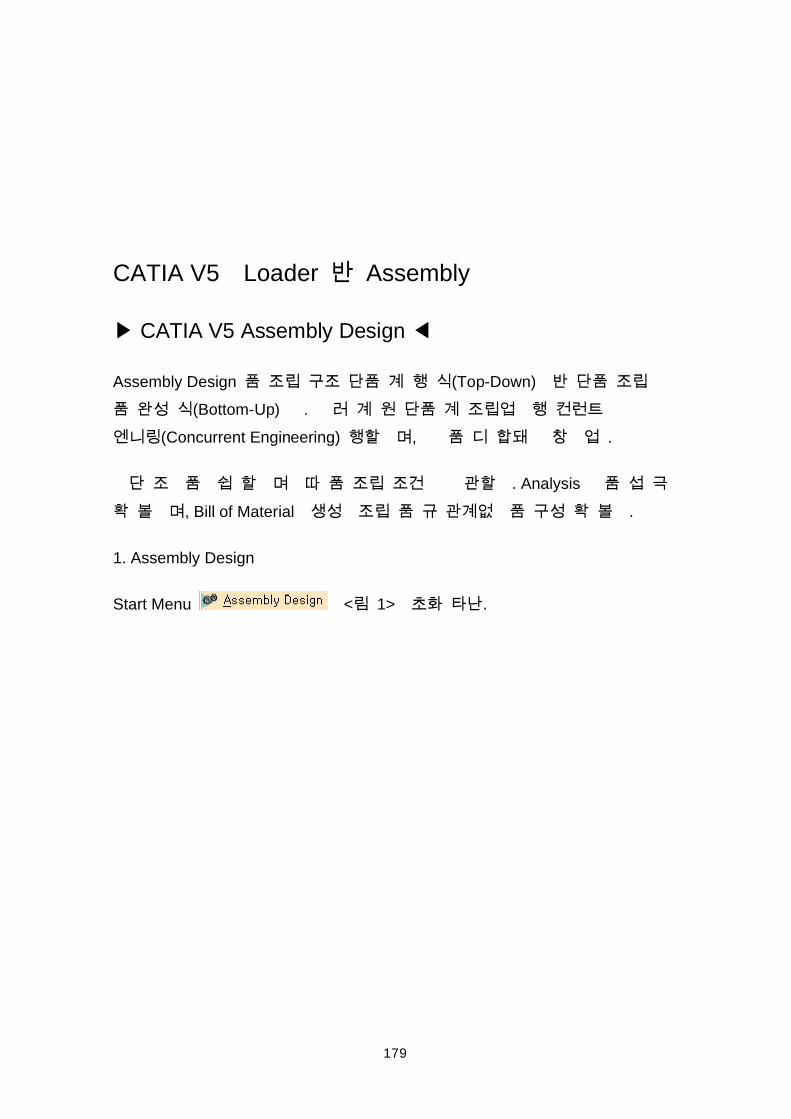
1. Assembly Design
149
(1)Pull-Down Menu Assembly Design .
(2) Workbench Assembly Design .
150
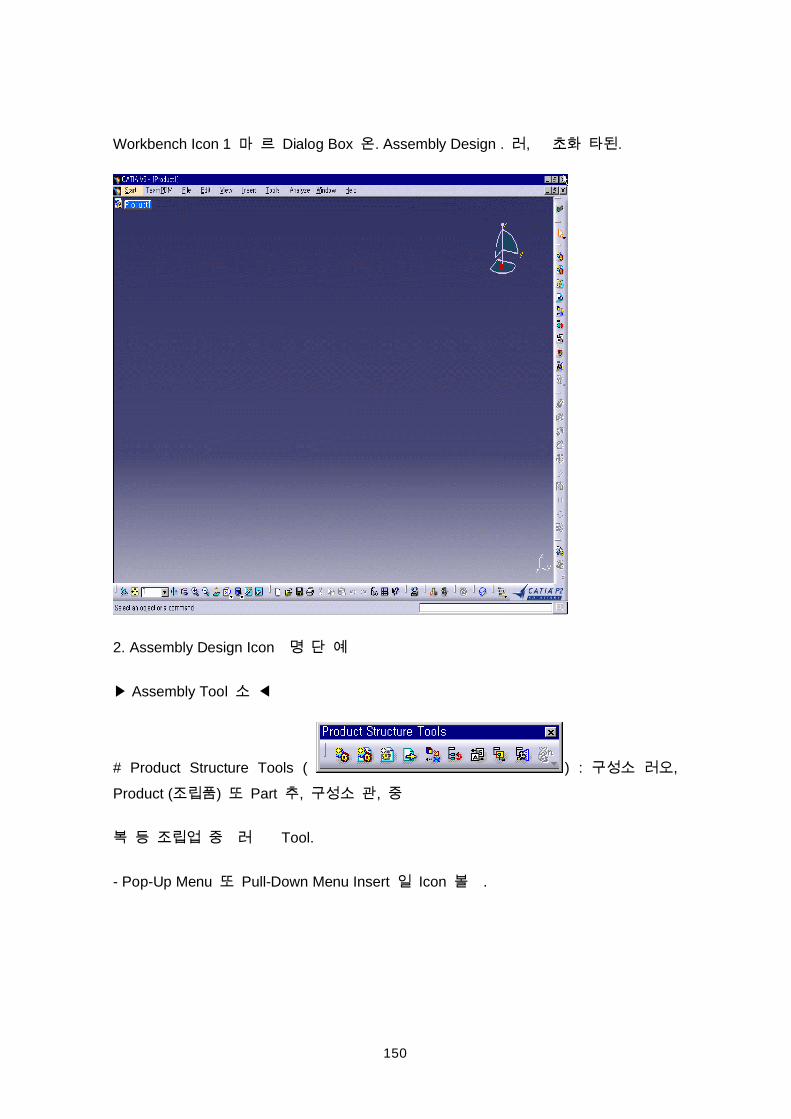
Workbench Icon 1 Dialog Box . Assembly Design . , .
2. Assembly Design Icon
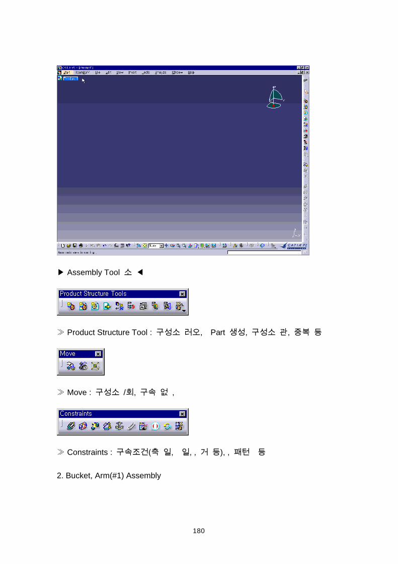
Assembly Tool
# Product Structure Tools ( ) : ,
Product ( ) Part , ,
Tool.
- Pop-Up Menu Pull-Down Menu Insert Icon .
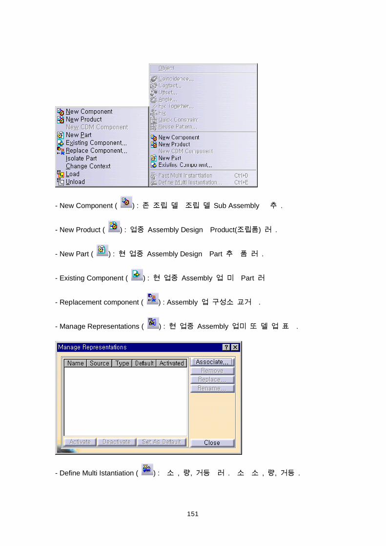
151
- New Component ( ) : Sub Assembly .
- New Product ( ) : Assembly Design Product( ) .
- New Part ( ) : Assembly Design Part .
- Existing Component ( ) : Assembly Part
- Replacement component ( ) : Assembly .
- Manage Representations ( ) : Assembly .
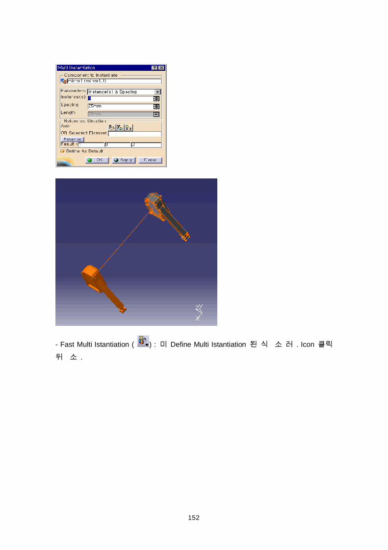
- Define Multi Istantiation ( ) : , , . , , .
152
- Fast Multi Istantiation ( ) : Define Multi Istantiation . Icon
.
153
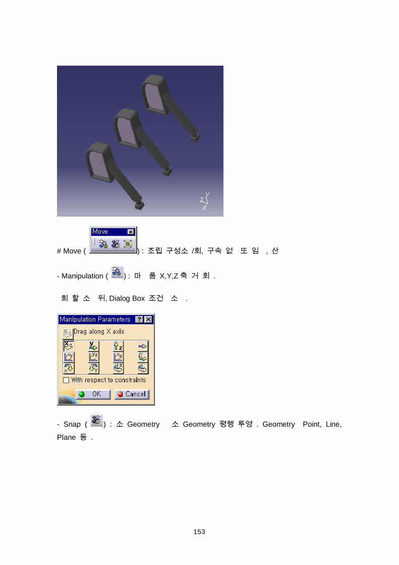
# Move ( ) : / , ,
- Manipulation ( ) : X,Y,Z .
, Dialog Box .
- Snap ( ) : Geometry Geometry . Geometry Point, Line,
Plane .
154
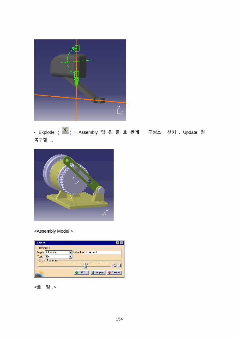
- Explode ( ) : Assembly . Update .
<Assembly Model >
.>
155
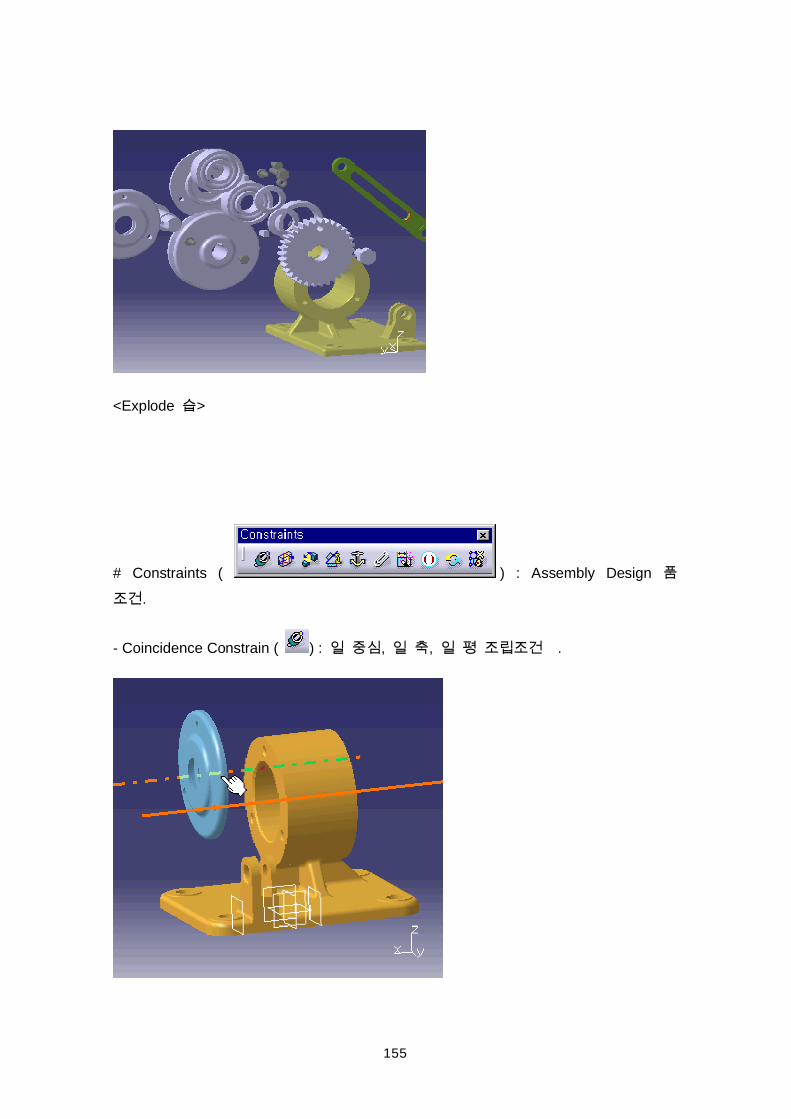
<Explode >
# Constraints ( ) : Assembly Design
.
- Coincidence Constrain ( ) : , , .
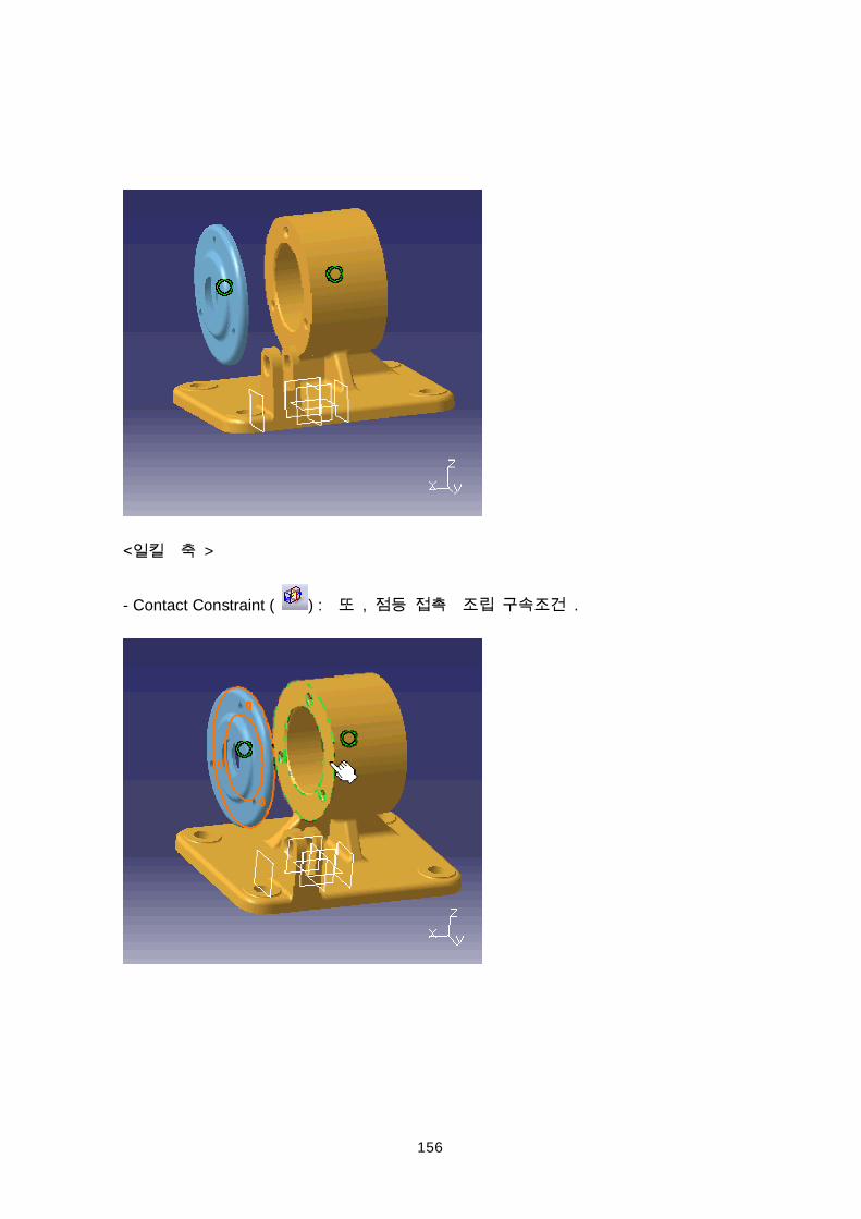
156
>
- Contact Constraint ( ) : , .
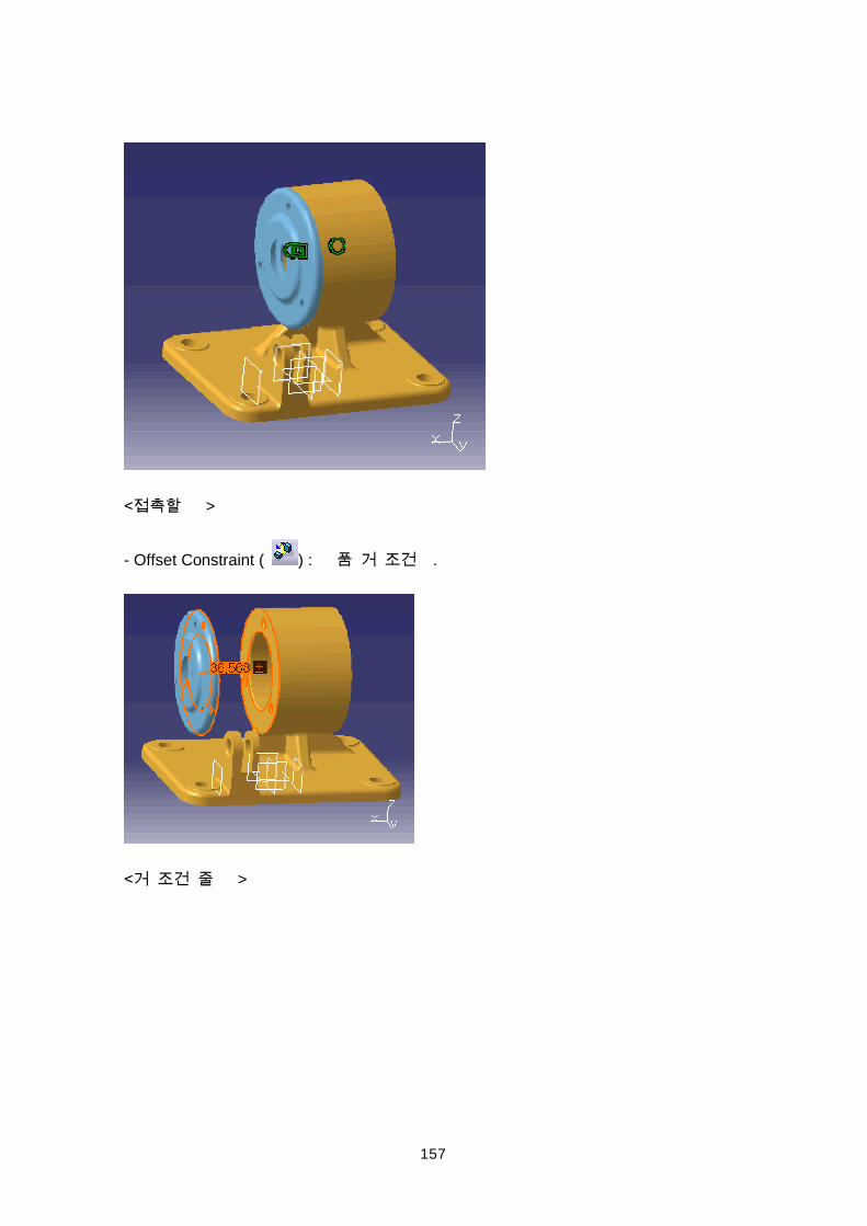
157
>
- Offset Constraint ( ) : .
>
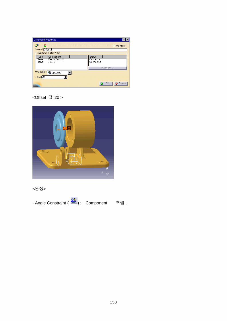
158
<Offset 20 >
>
- Angle Constraint ( ) : Component .
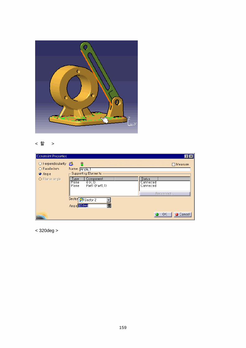
159
< >
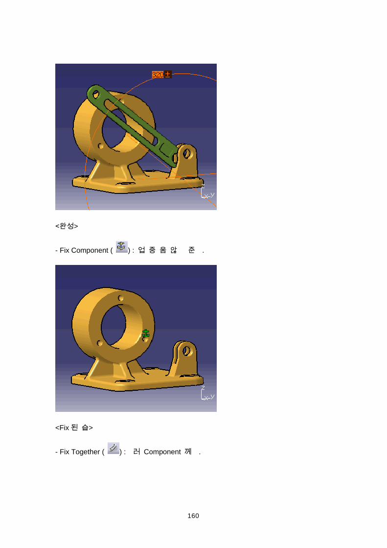
< 320deg >
160
>
- Fix Component ( ) : .
<Fix >
- Fix Together ( ) : Component .
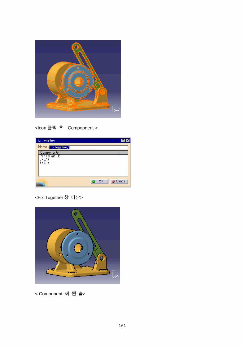
161
<Icon Compopnent >
<Fix Together >
< Component >
162
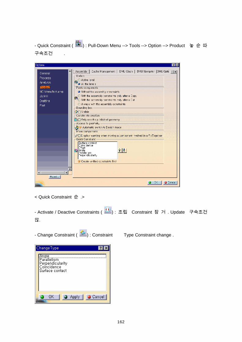
- Quick Constraint ( ) : Pull-Down Menu --> Tools --> Option --> Product
.
< Quick Constraint .>
- Activate / Deactive Constraints ( ) : Constraint . Update .
- Change Constraint ( ) : Constraint Type Constraint change .
163
Constraint .>
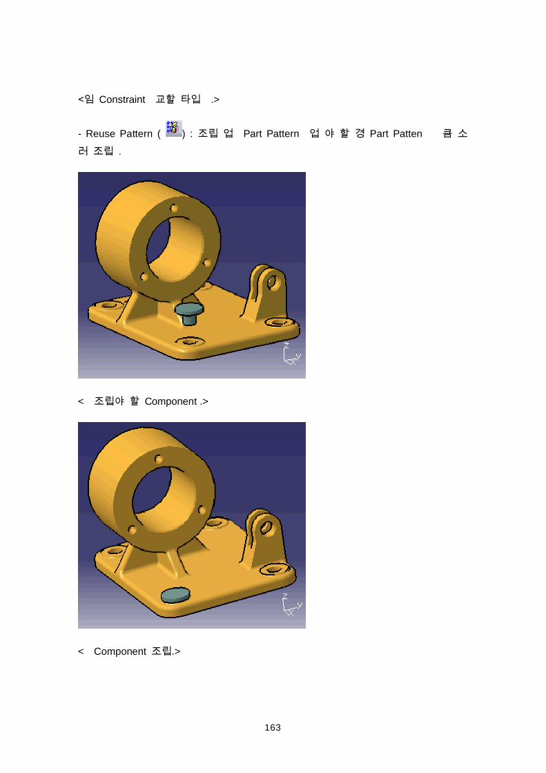
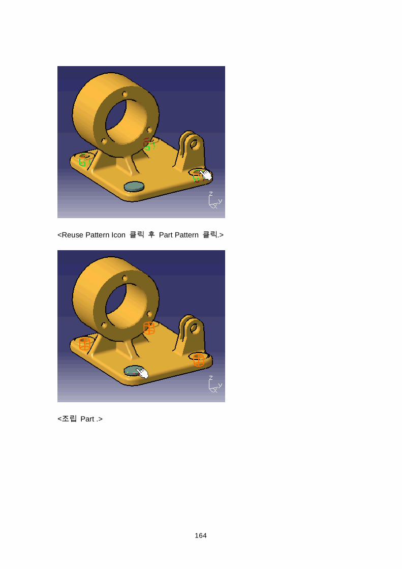
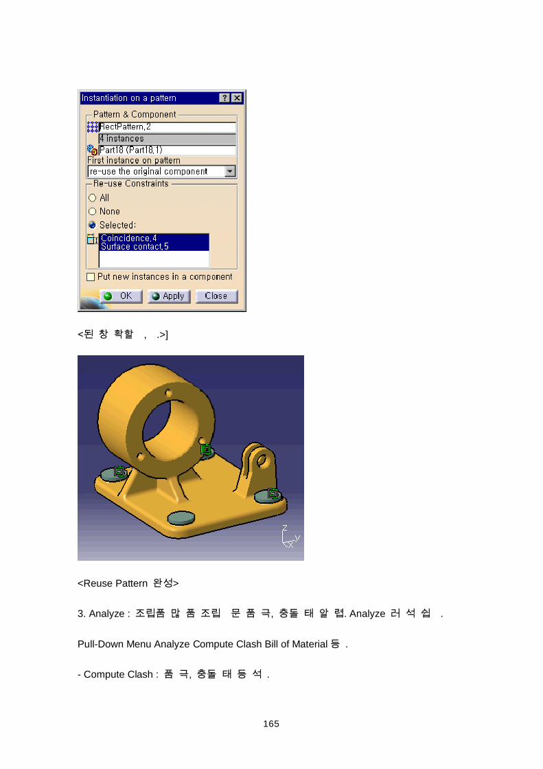
- Reuse Pattern ( ) : Part Pattern Part Patten .
< Component .>
< Component .>
164
<Reuse Pattern Icon Part Pattern .>
Part .>
165
, .>]
<Reuse Pattern >
3. Analyze : , . Analyze .
Pull-Down Menu Analyze Compute Clash Bill of Material .
- Compute Clash : , .
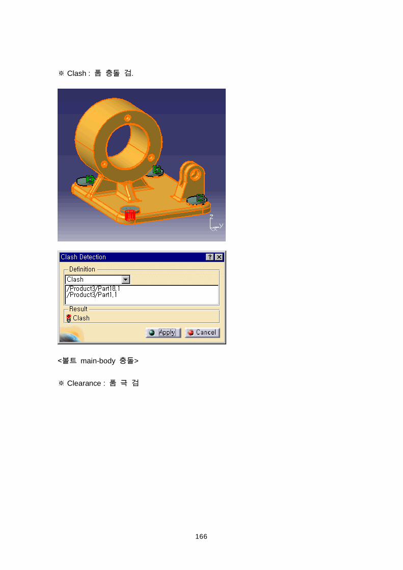
166
Clash : .
main-body >
Clearance :
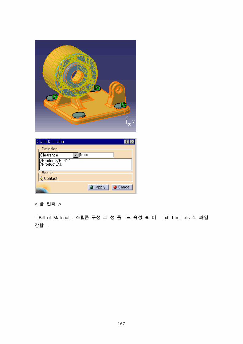
167
< .>
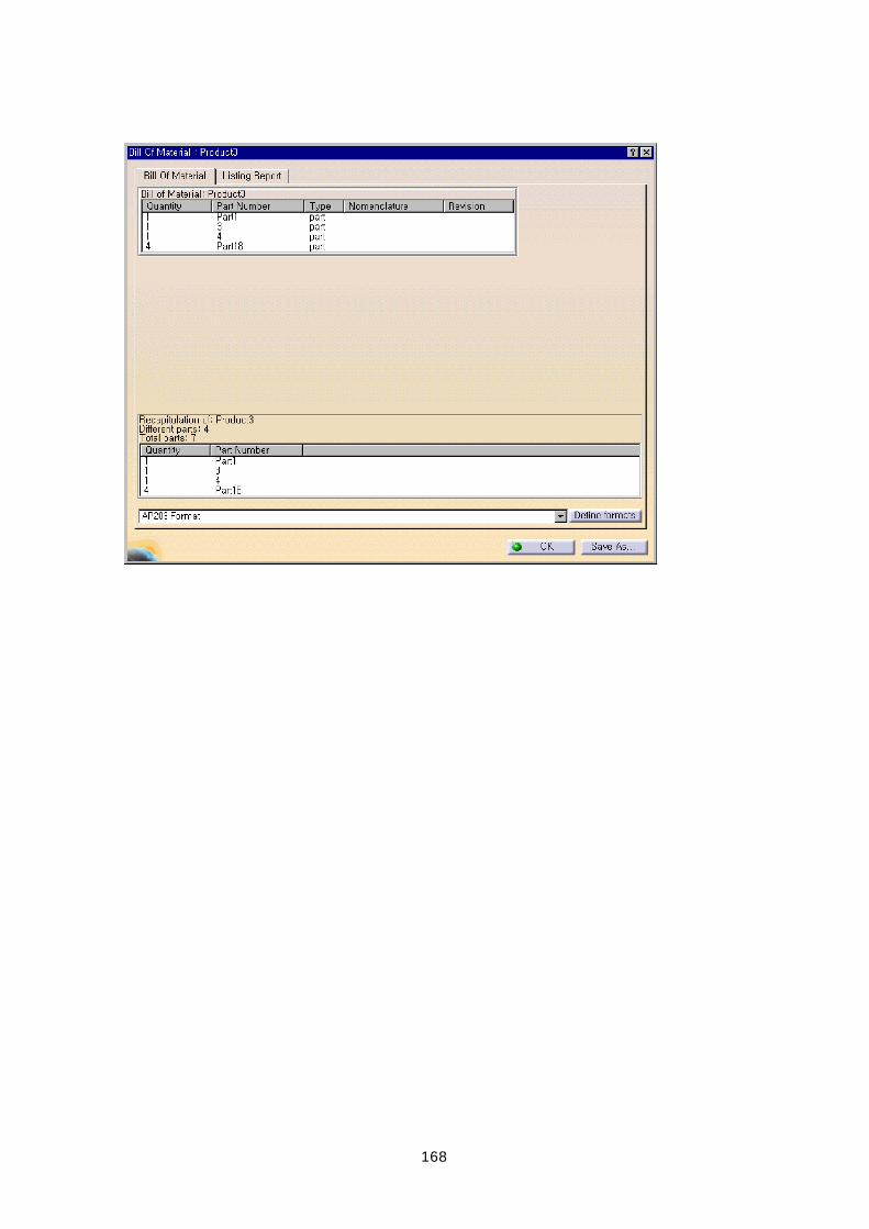
- Bill of Material : txt, html, xls
.
168
169
CATIA V5 Loader
<1> Bucket
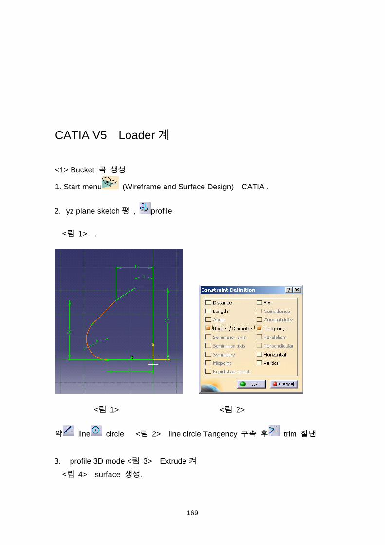
1. Start menu (Wireframe and Surface Design) CATIA .
2. yz plane sketch , profile
1> .
1> < 2>
line circle < 2> line circle Tangency trim
3. profile 3D mode < 3> Extrude 4> surface .
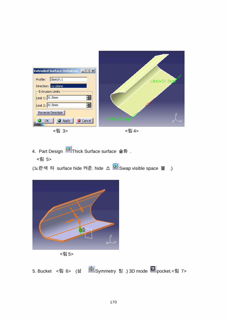
170
3> 4>
4. Part Design Thick Surface surface . 5>
surface hide . hide Swap visible space .)
5>
5. Bucket < 6> ( Symmetry .) 3D mode pocket.< 7>
171
6> 7>
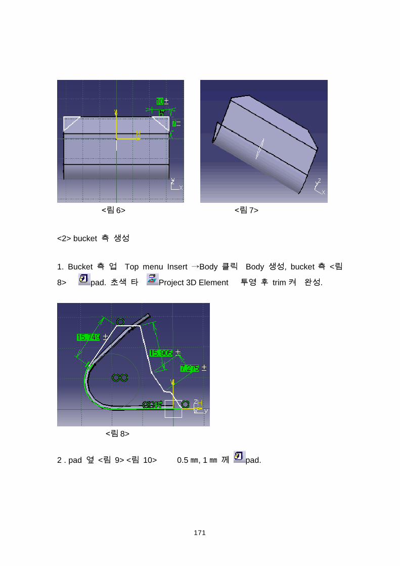
<2> bucket
1. Bucket Top menu Insert Body Body , bucket <
8> pad. Project 3D Element trim .
8>
2 . pad < 9> < 10> 0.5 , 1 pad.
172
9> 10>
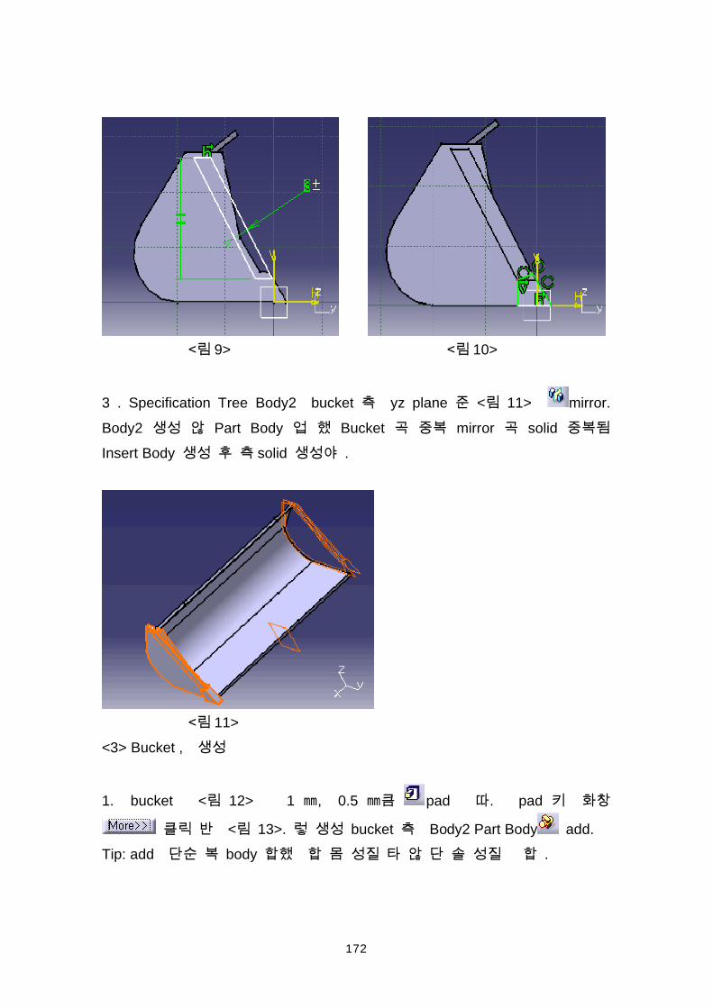
3 . Specification Tree Body2 bucket yz plane < 11> mirror.Body2 Part Body Bucket mirror solid Insert Body solid .
11><3> Bucket ,
1. bucket < 12> 1 , 0.5 pad . pad
< 13>. bucket Body2 Part Body add.Tip: add body .
173
12> 13>
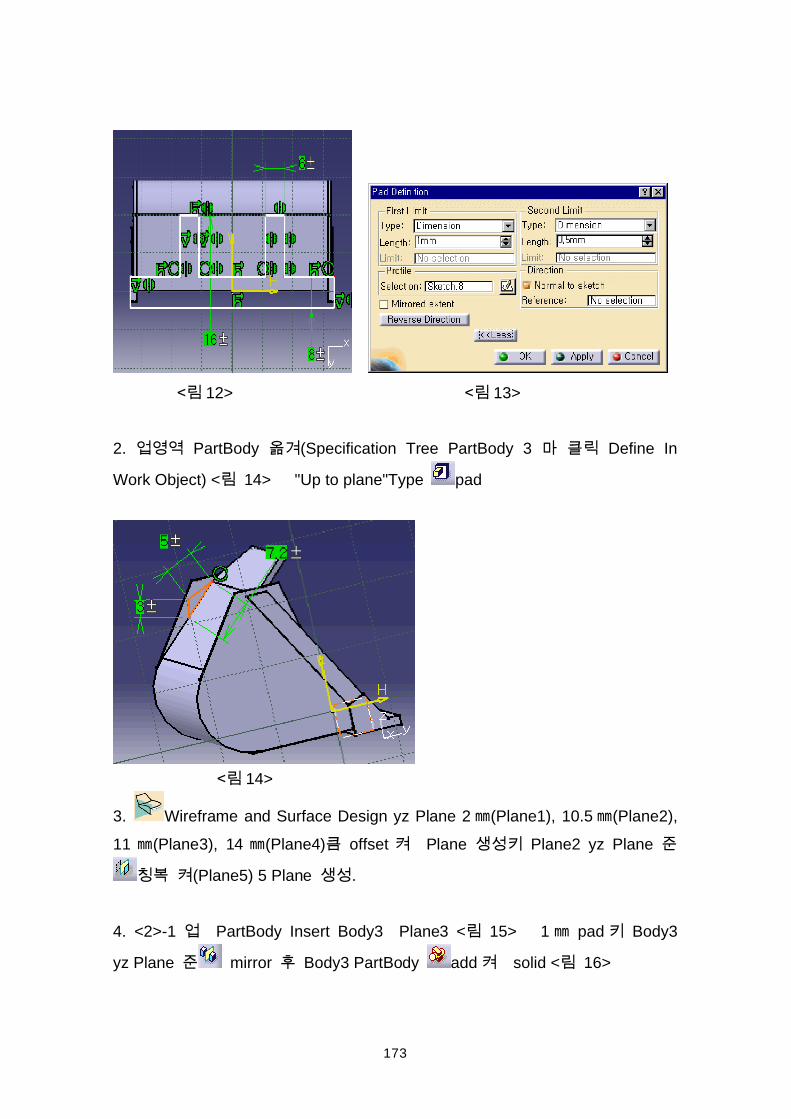
2. PartBody (Specification Tree PartBody 3 Define In
Work Object) < 14> "Up to plane"Type pad
14>
3. Wireframe and Surface Design yz Plane 2 (Plane1), 10.5 (Plane2),11 (Plane3), 14 (Plane4) offset Plane Plane2 yz Plane
(Plane5) 5 Plane .
4. <2>-1 PartBody Insert Body3 Plane3 < 15> 1 pad Body3
yz Plane mirror Body3 PartBody add solid < 16>
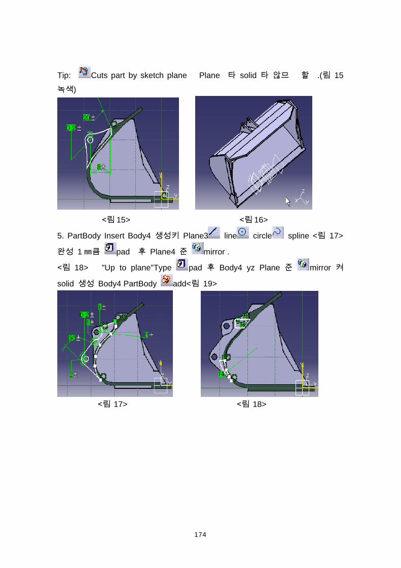
174
Tip: Cuts part by sketch plane Plane solid .( 15)
15> 16>
5. PartBody Insert Body4 Plane3 line circle spline < 17>
1 pad Plane4 mirror .
18> "Up to plane"Type pad Body4 yz Plane mirror
solid Body4 PartBody add< 19>
17> 18>
175
< 19>
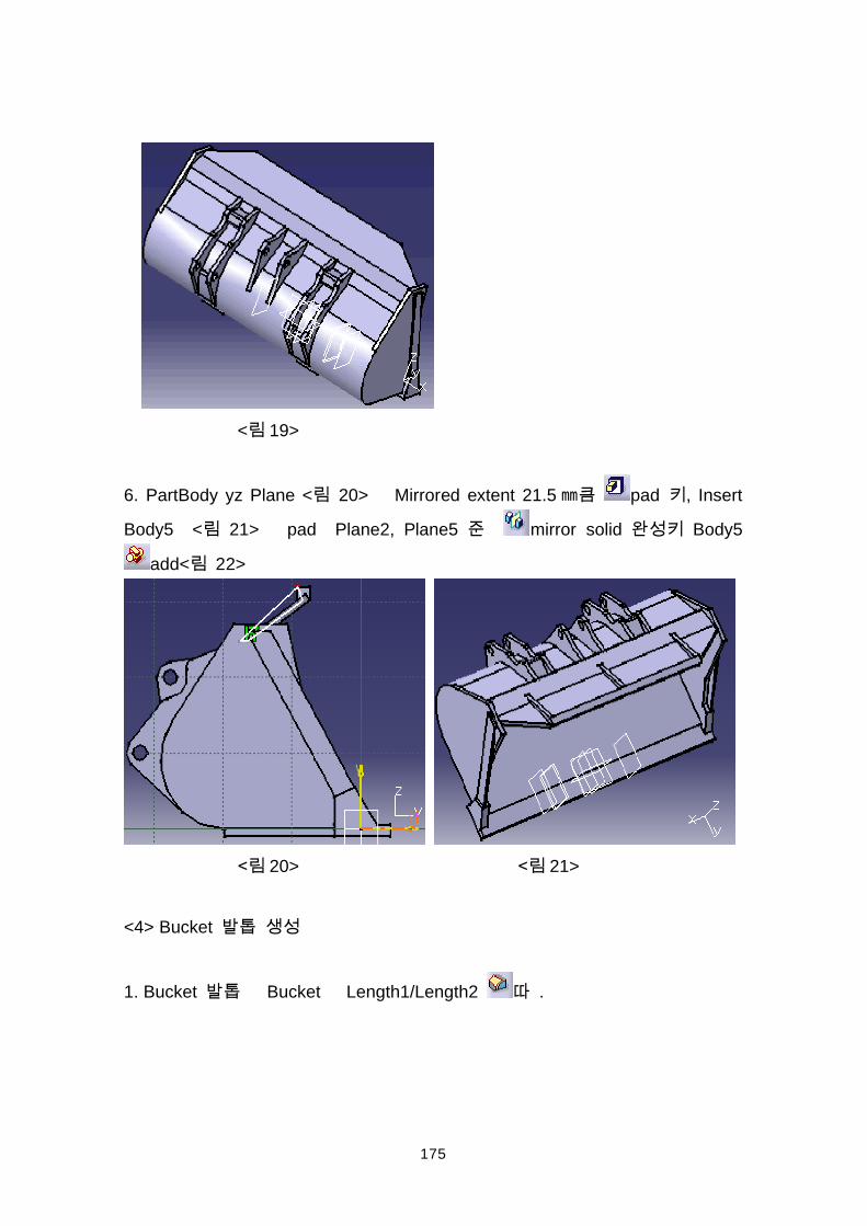
6. PartBody yz Plane < 20> Mirrored extent 21.5 pad , Insert
Body5 < 21> pad Plane2, Plane5 mirror solid Body5
add< 22>
20> 21>
<4> Bucket
1. Bucket Bucket Length1/Length2 .
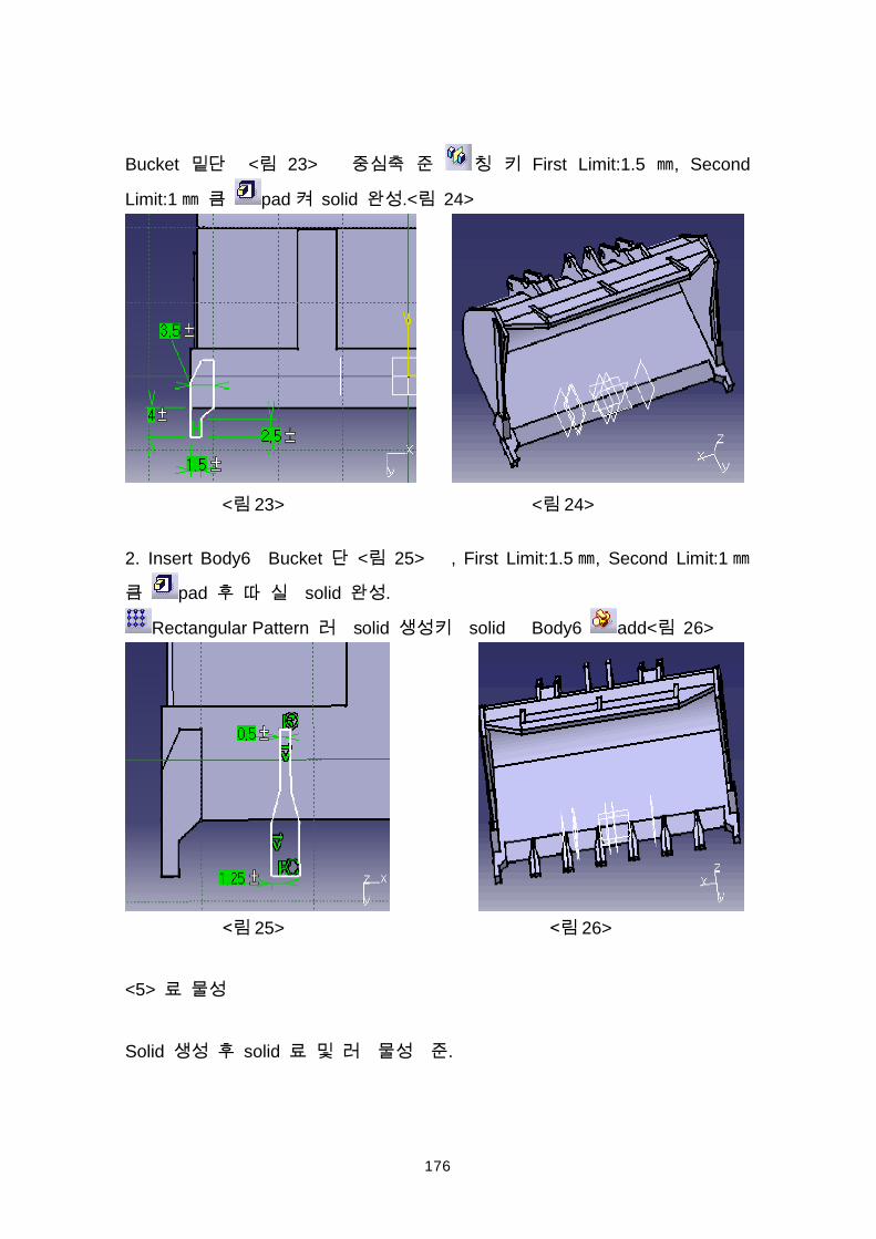
176
Bucket < 23> First Limit:1.5 , Second
Limit:1 pad solid .< 24>
< 23> < 24>
2. Insert Body6 Bucket < 25> , First Limit:1.5 , Second Limit:1
pad solid .
Rectangular Pattern solid solid Body6 add< 26>
25> 26>
<5>
Solid solid .
177
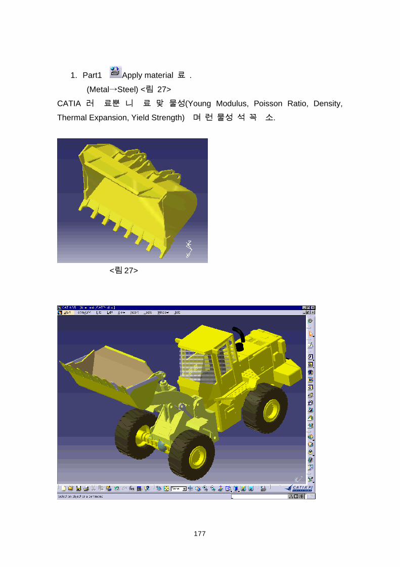
1. Part1 Apply material .(Metal Steel) < 27>
CATIA (Young Modulus, Poisson Ratio, Density,Thermal Expansion, Yield Strength) .
< 27>
178
179
CATIA V5 Loader Assembly
CATIA V5 Assembly Design
Assembly Design (Top-Down) (Bottom-Up) .
(Concurrent Engineering) , .
. Analysis , Bill of Material .
1. Assembly Design
Start Menu < 1> .
180
Assembly Tool
Product Structure Tool : , Part , ,
Move : / , ,
Constraints : , , , ), ,
2. Bucket, Arm(#1) Assembly
181
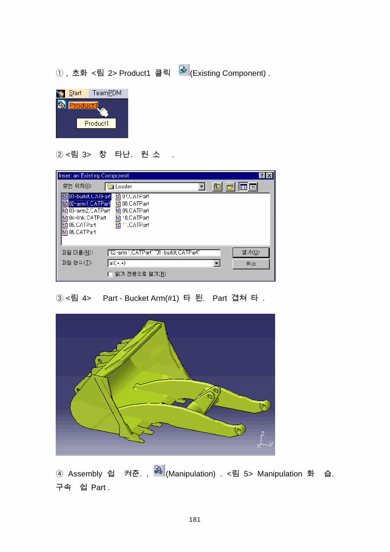
, < 2> Product1 (Existing Component) .
< 3> . .
< 4> Part - Bucket Arm(#1) . Part .
Assembly . , (Manipulation) . < 5> Manipulation . Part .
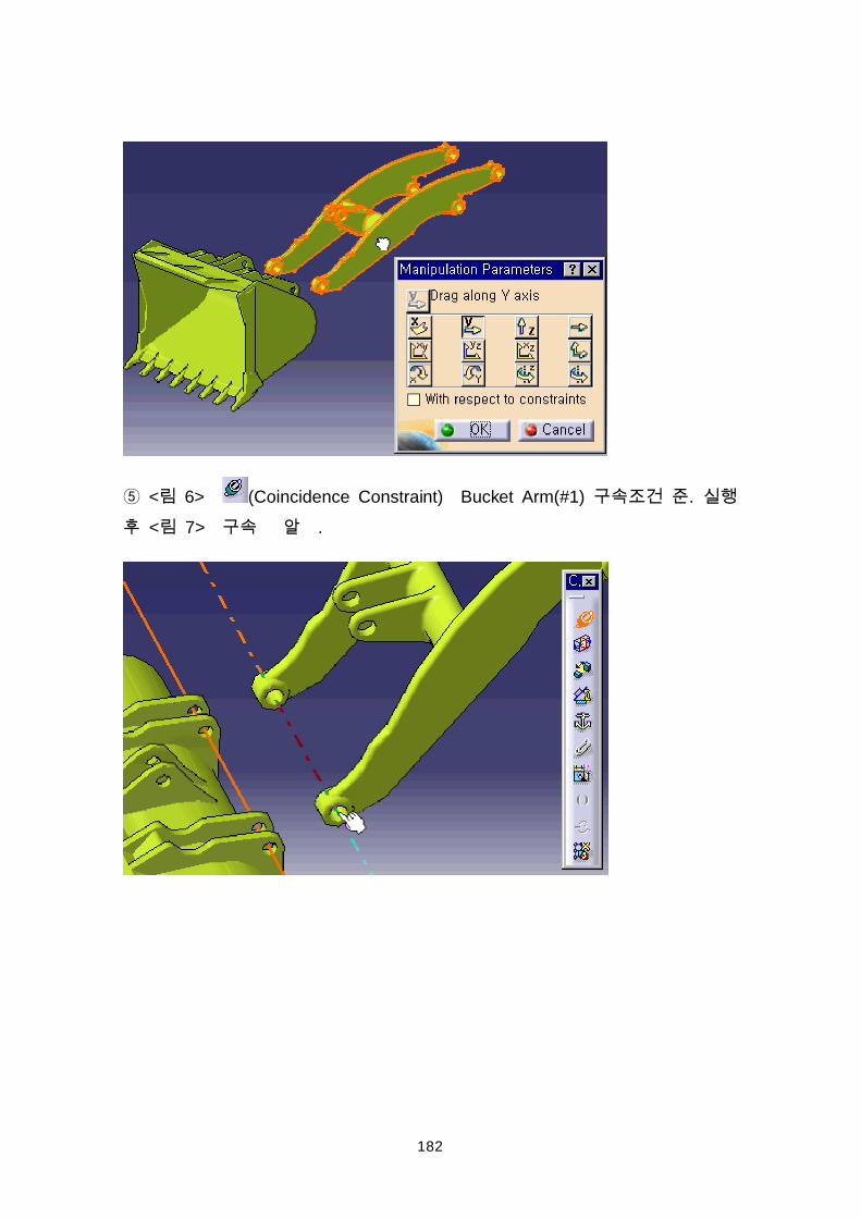
182
< 6> (Coincidence Constraint) Bucket Arm(#1) . < 7> .
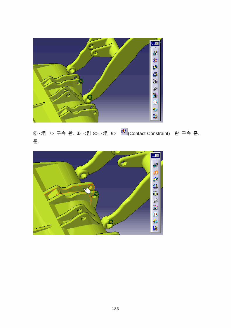
183
< 7> . < 8>, < 9> (Contact Constraint) ..
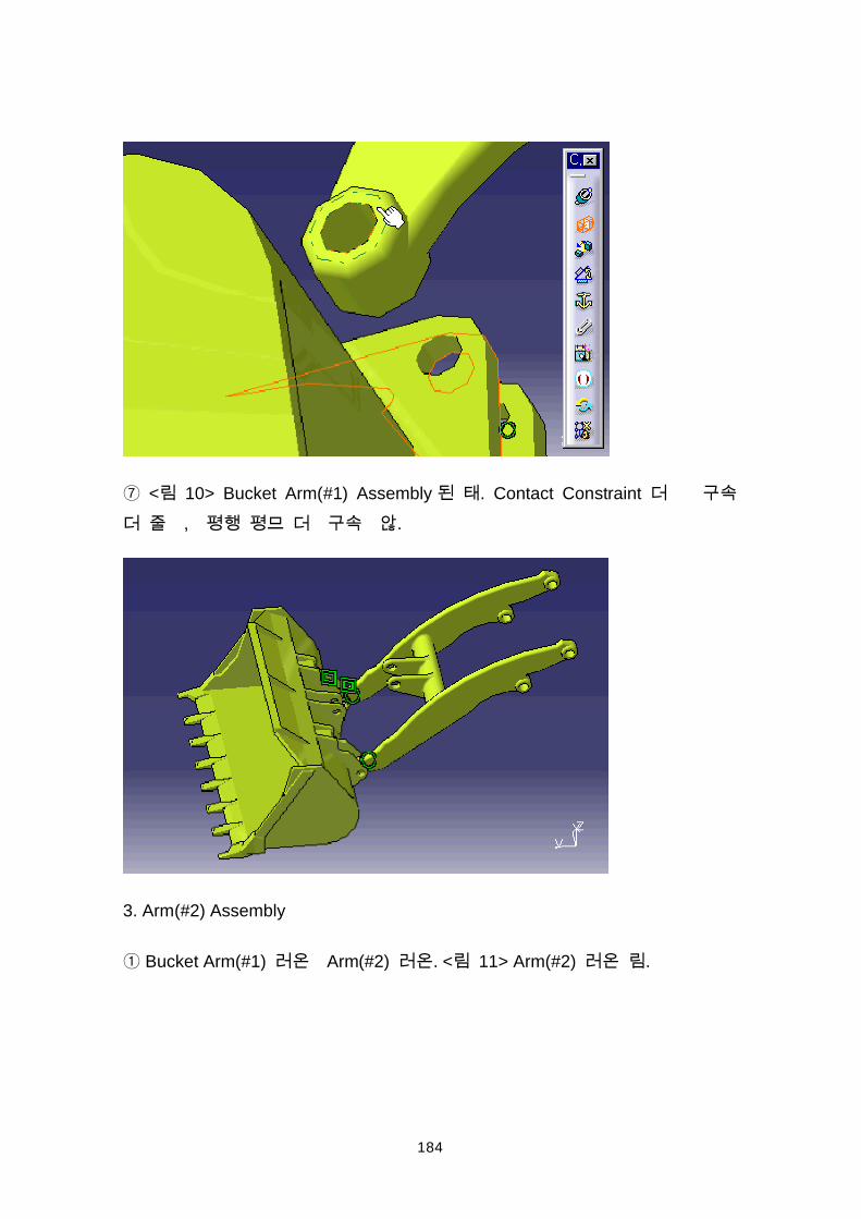
184
< 10> Bucket Arm(#1) Assembly . Contact Constraint , .
3. Arm(#2) Assembly
Bucket Arm(#1) Arm(#2) . < 11> Arm(#2) .
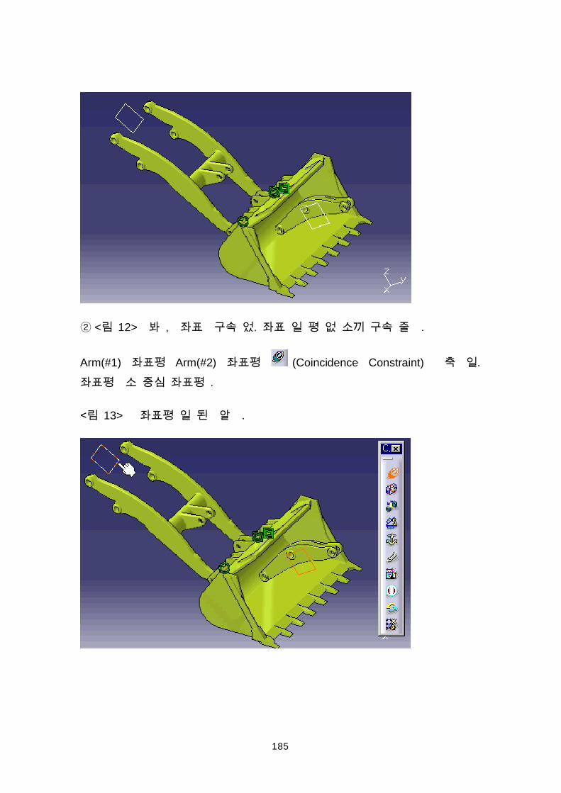
185
< 12> , . .
Arm(#1) Arm(#2) (Coincidence Constraint) . .
13> .
186
Hide/Show
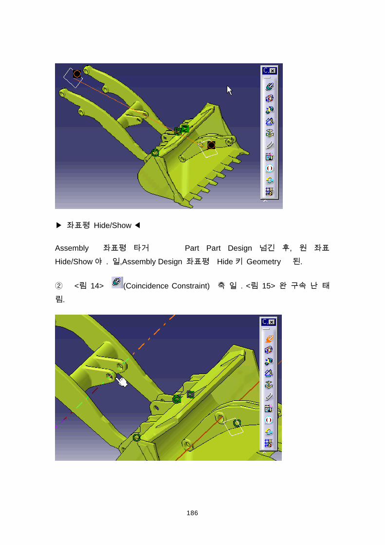
Assembly Part Part Design , Hide/Show . ,Assembly Design Hide Geometry .
< 14> (Coincidence Constraint) . < 15> .
187
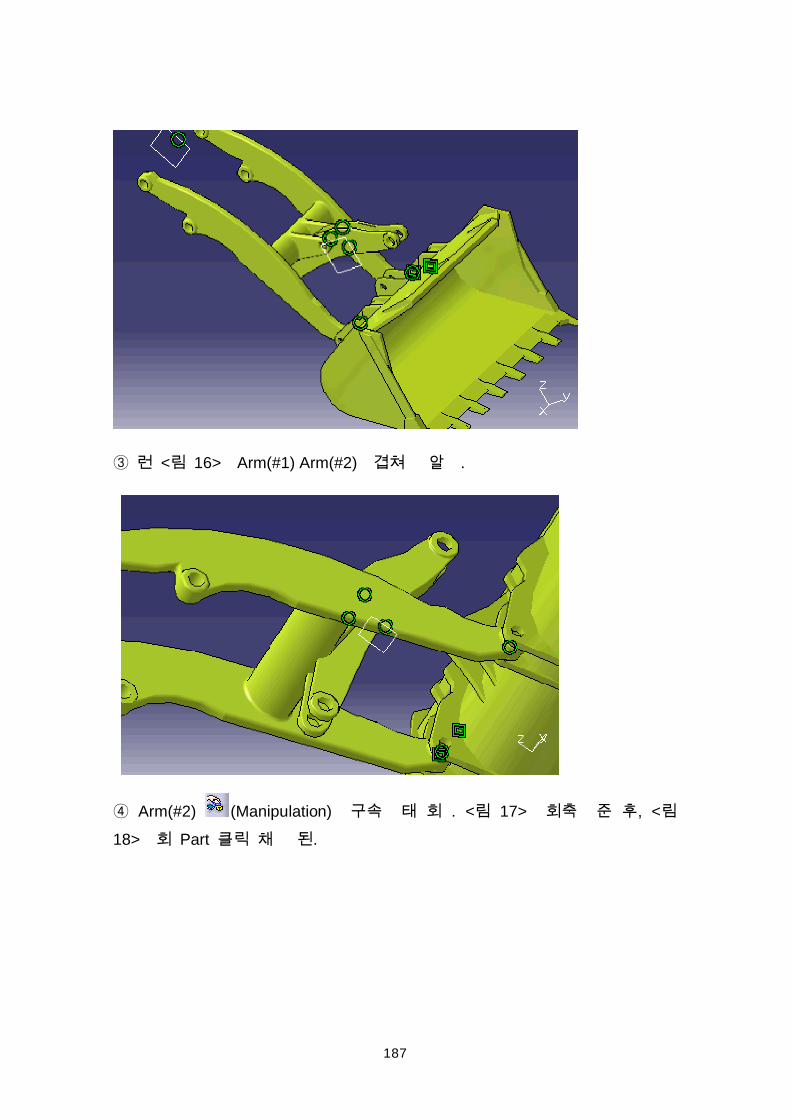
< 16> Arm(#1) Arm(#2) .
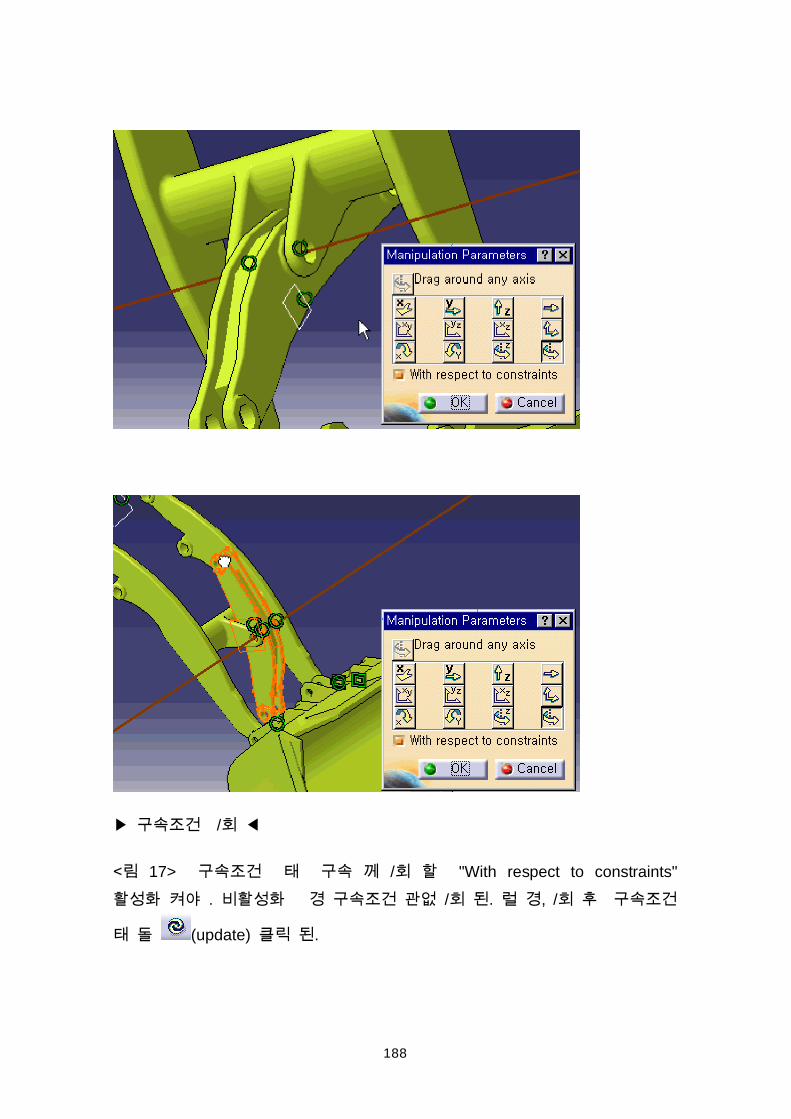
Arm(#2) (Manipulation) . < 17> , <18> Part .
188
/
17> / "With respect to constraints" . / . , /
(update) .
189
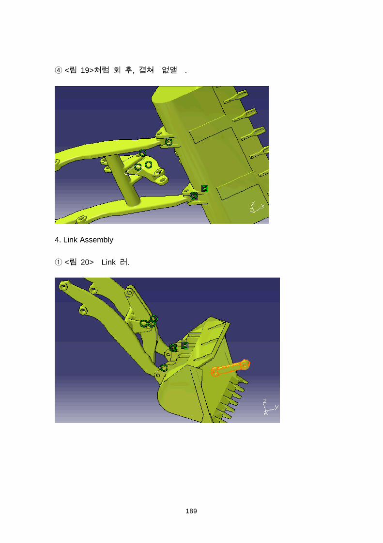
< 19> , .
4. Link Assembly
< 20> Link .
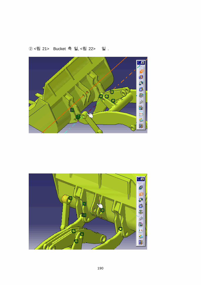
190
< 21> Bucket , < 22> .
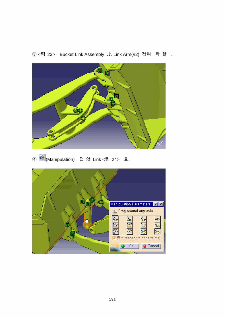
191
< 23> Bucket Link Assembly . Link Arm(#2) .
(Manipulation) Link < 24> .
192
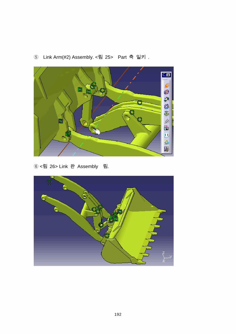
Link Arm(#2) Assembly. < 25> Part .
< 26> Link Assembly .
193
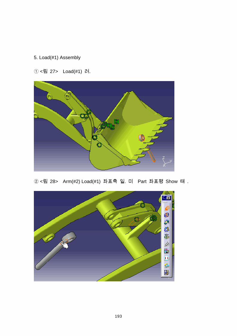
5. Load(#1) Assembly
< 27> Load(#1) .
< 28> Arm(#2) Load(#1) . Part Show .
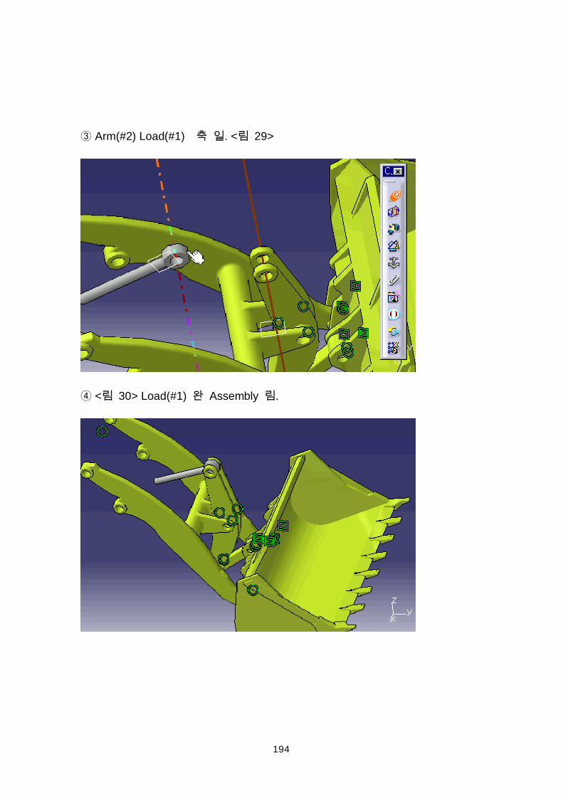
194
Arm(#2) Load(#1) . < 29>
< 30> Load(#1) Assembly .
195
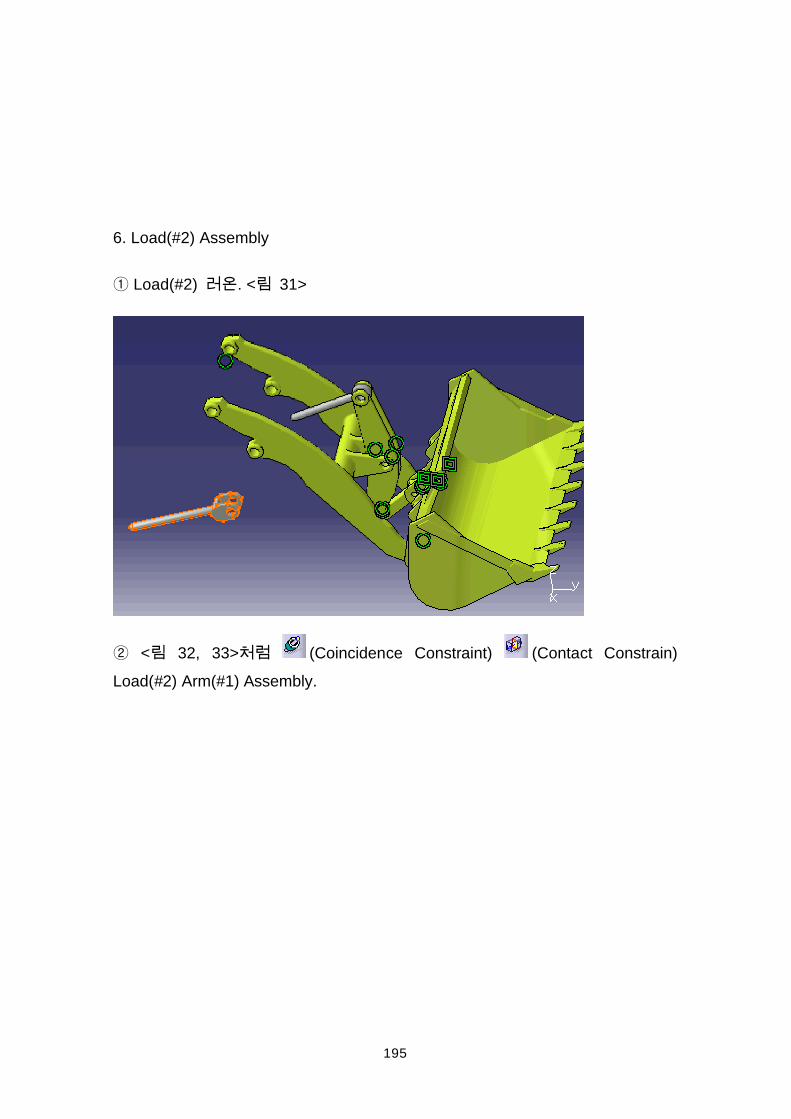
6. Load(#2) Assembly
Load(#2) . < 31>
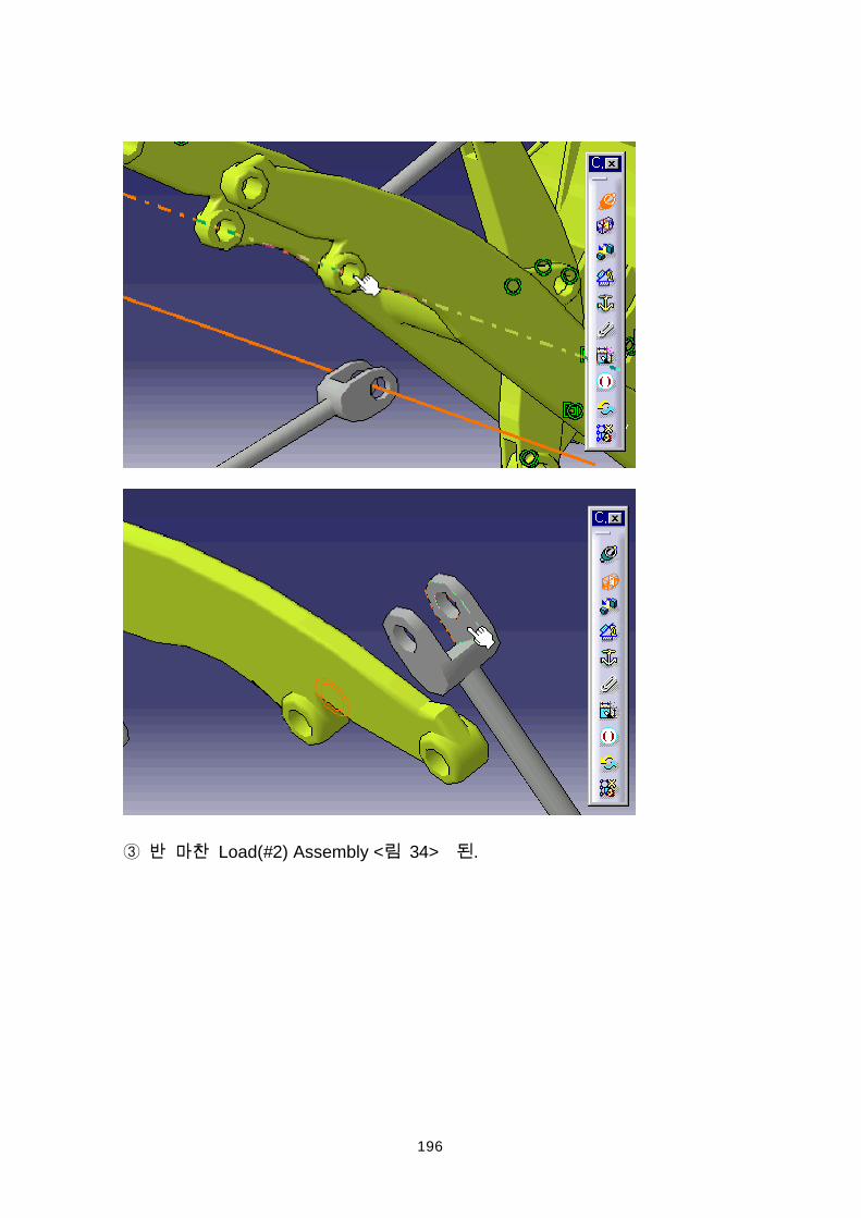
< 32, 33> (Coincidence Constraint) (Contact Constrain)Load(#2) Arm(#1) Assembly.
196
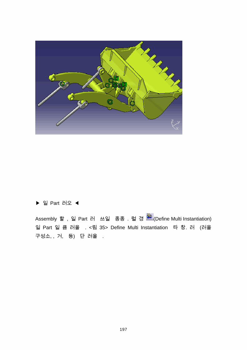
Load(#2) Assembly < 34> .
197
Part
Assembly , Part . (Define Multi Instantiation) Part . < 35> Define Multi Instantiation . (
, , , ) .
198
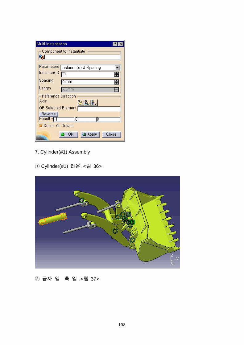
7. Cylinder(#1) Assembly
Cylinder(#1) . < 36>
.< 37>
199
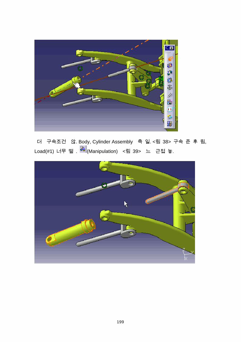
. Body, Cylinder Assembly . < 38> ,
Load(#1) . (Manipulation) < 39> .
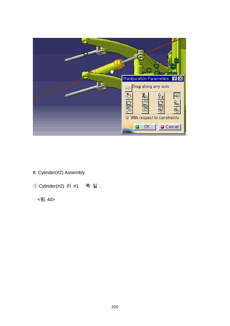
200
8. Cylinder(#2) Assembly
Cylinder(#2) #1 .
40>
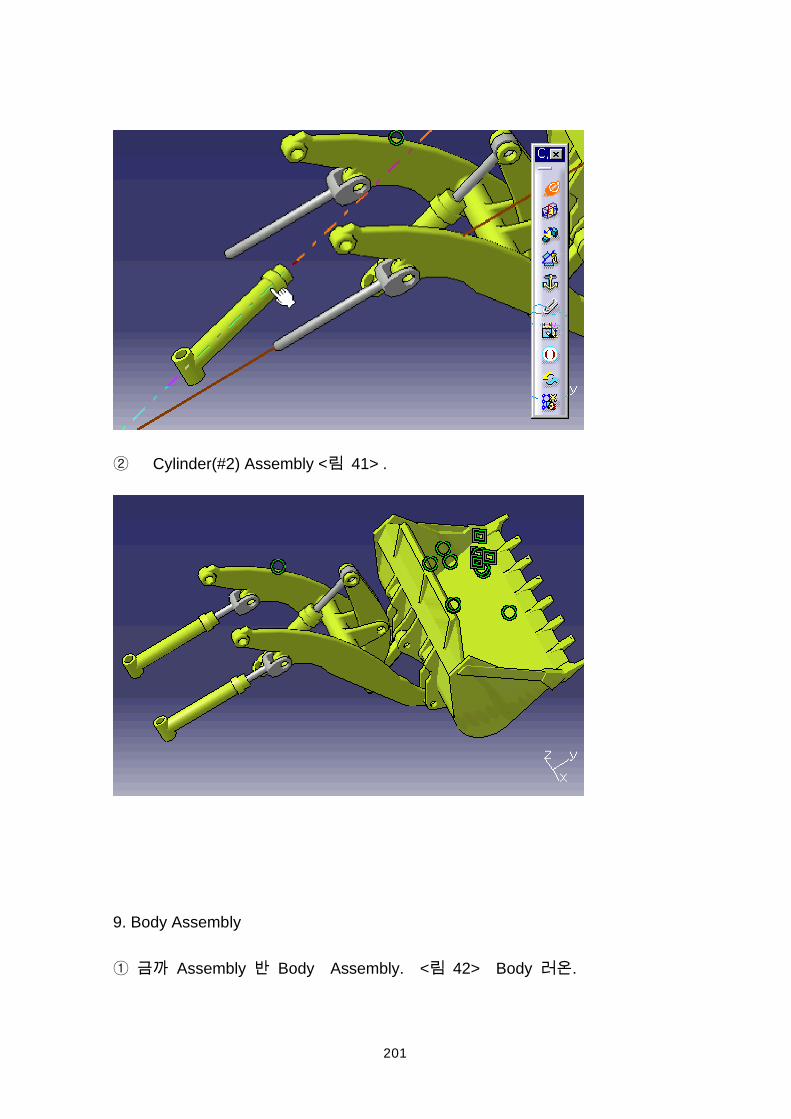
201
Cylinder(#2) Assembly < 41> .
9. Body Assembly
Assembly Body Assembly. < 42> Body .
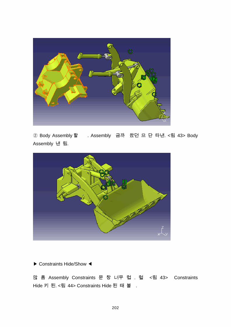
202
Body Assembly . Assembly . < 43> BodyAssembly .
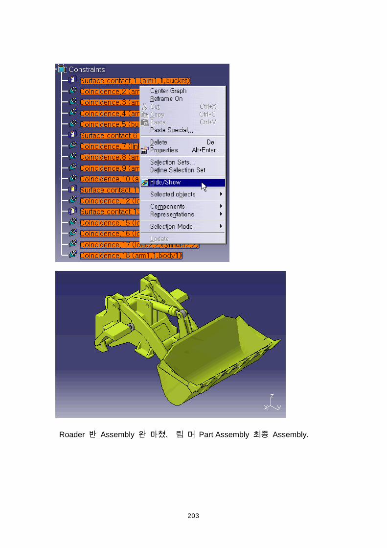
Constraints Hide/Show
Assembly Constraints . < 43> ConstraintsHide . < 44> Constraints Hide .
203
Roader Assembly . Part Assembly Assembly.
204
205
206
207
208
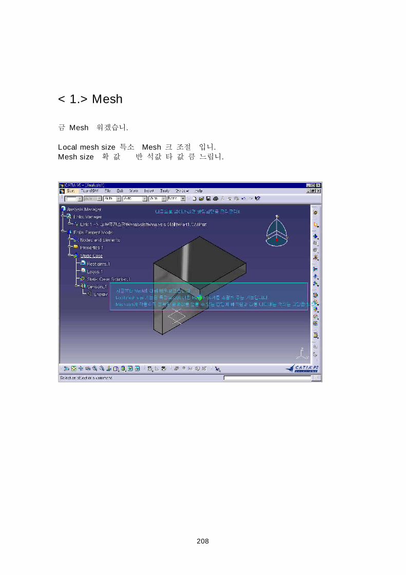
< 1.> Mesh
Mesh .
Local mesh size Mesh .
Mesh size .
209
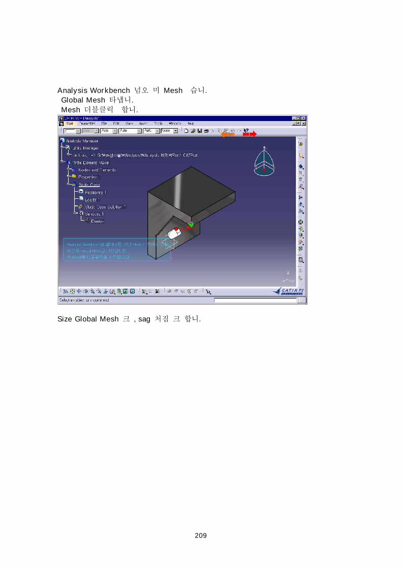
Analysis Workbench Mesh .
Global Mesh .
Mesh .
Size Global Mesh , sag .
210
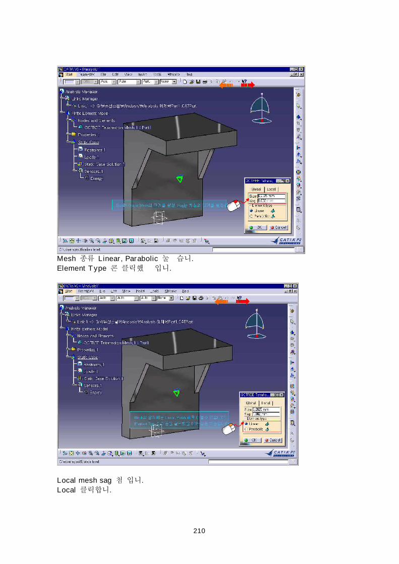
Mesh Linear, Parabolic .
Element Type .
Local mesh sag .
Local .
211
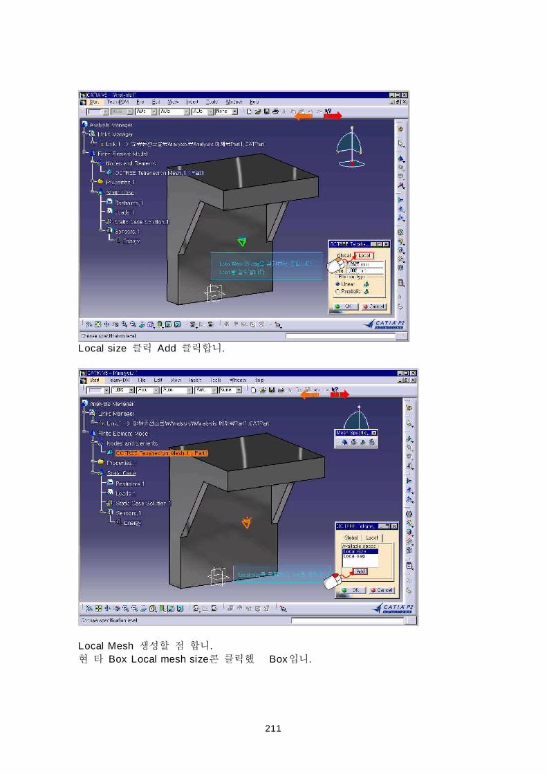
Local size Add .
Local Mesh .
Box Local mesh size Box .
212
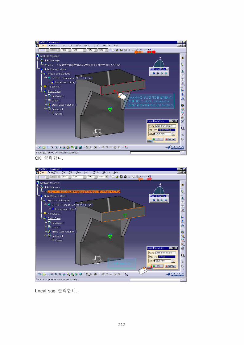
OK .
Local sag .
213
Add .
Local sag .
Box Local Mesh Sag Box .

214
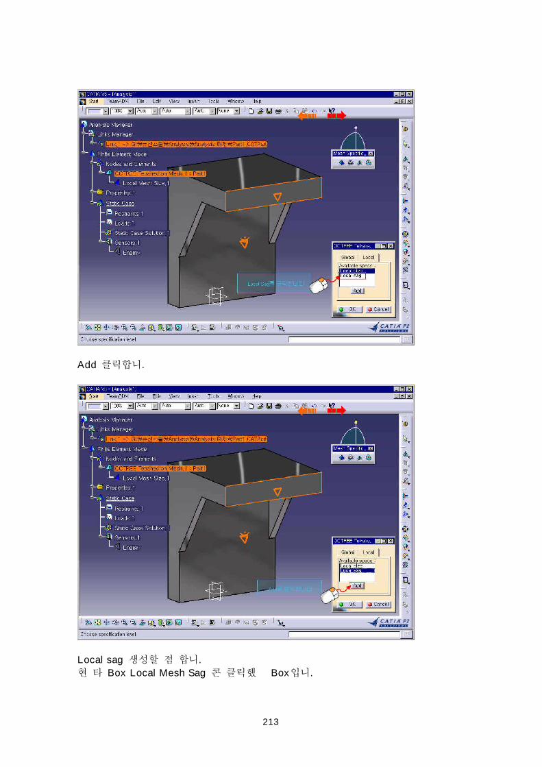
OK .
OK .
215
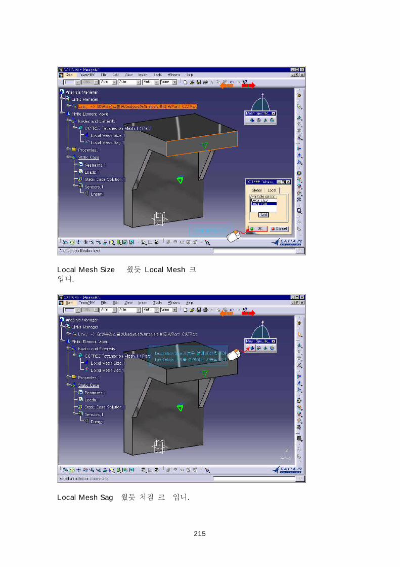
Local Mesh Size Local Mesh
.
Local Mesh Sag .
216
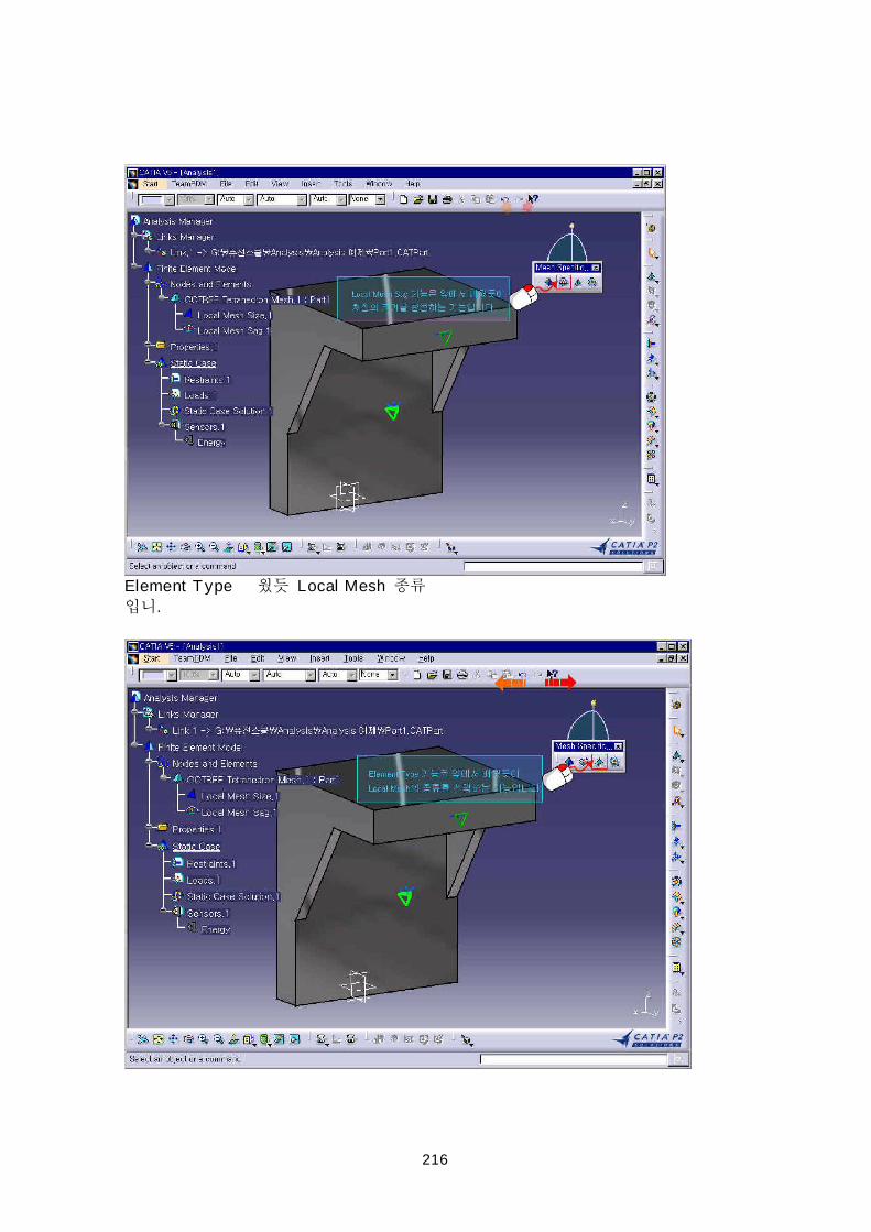
Element Type Local Mesh
.
217
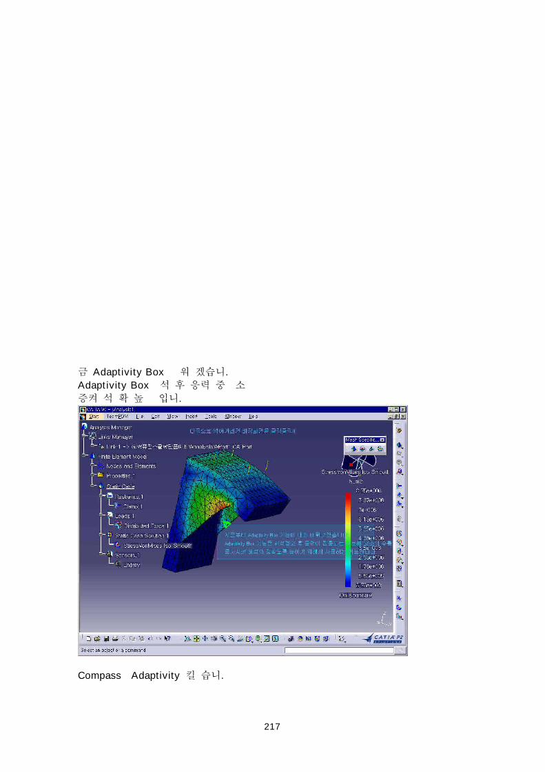
Adaptivity Box .
Adaptivity Box
.
Compass Adaptivity .
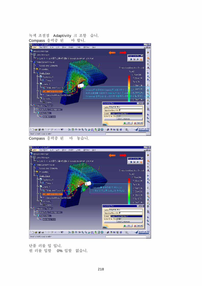
218
Adaptivity .
Compass .
Compass .
.
0% .
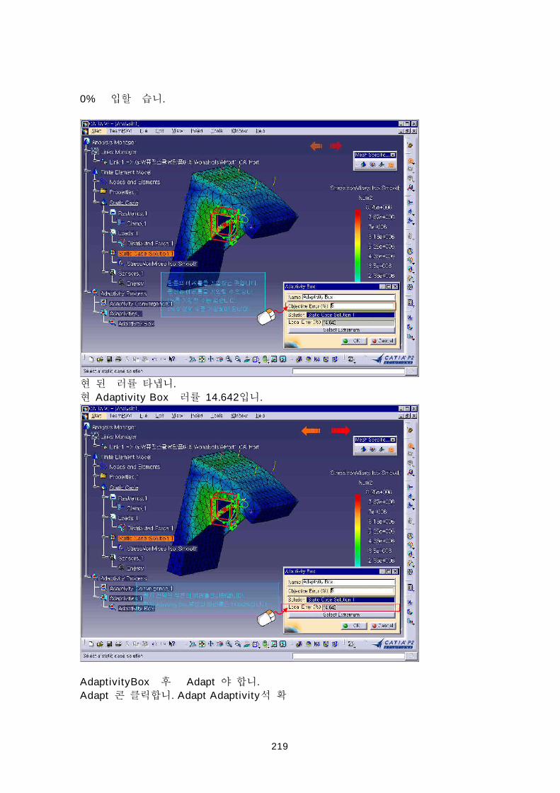
219
0% .
.
Adaptivity Box 14.642 .
AdaptivityBox Adapt .
Adapt . Adapt Adaptivity
220
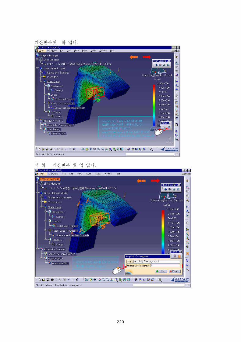
.
.
221
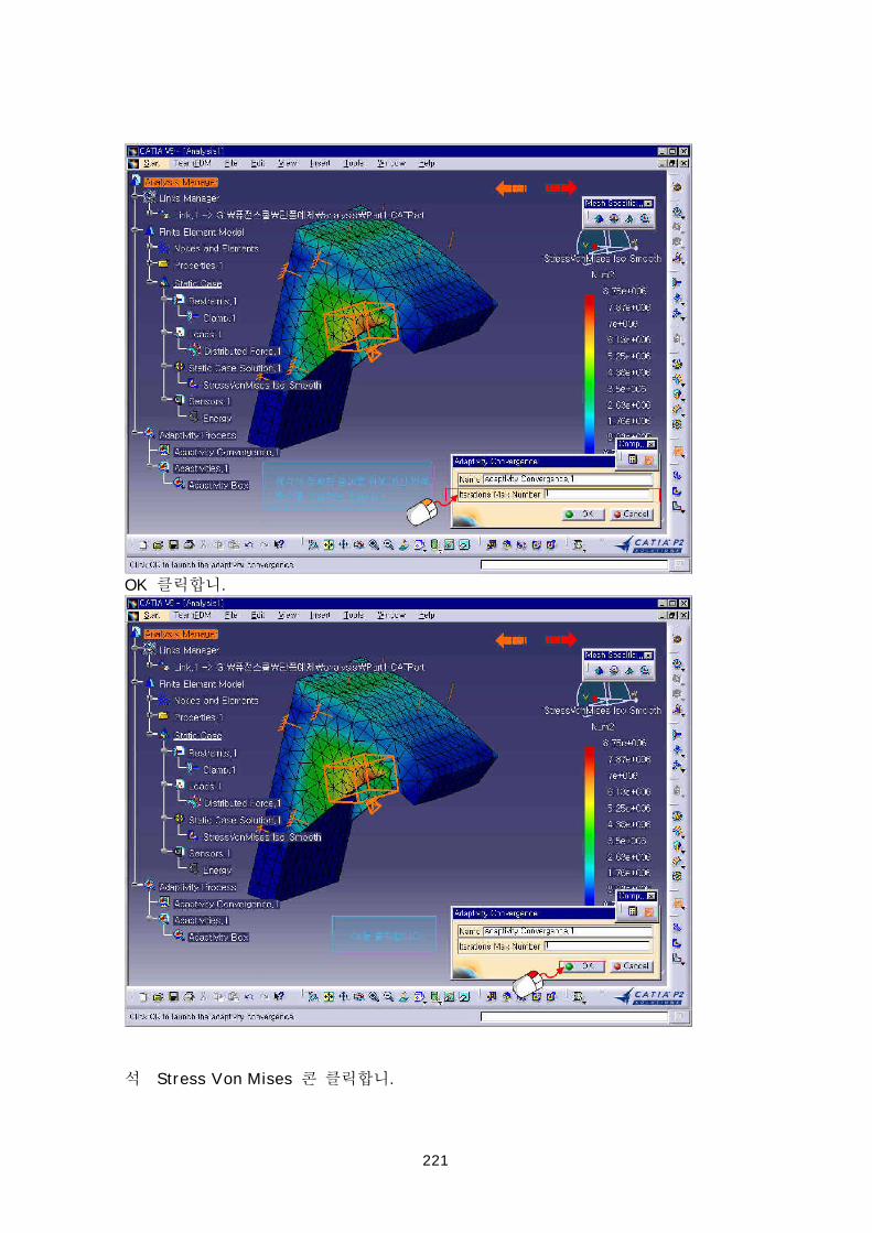
OK .
Stress Von Mises .
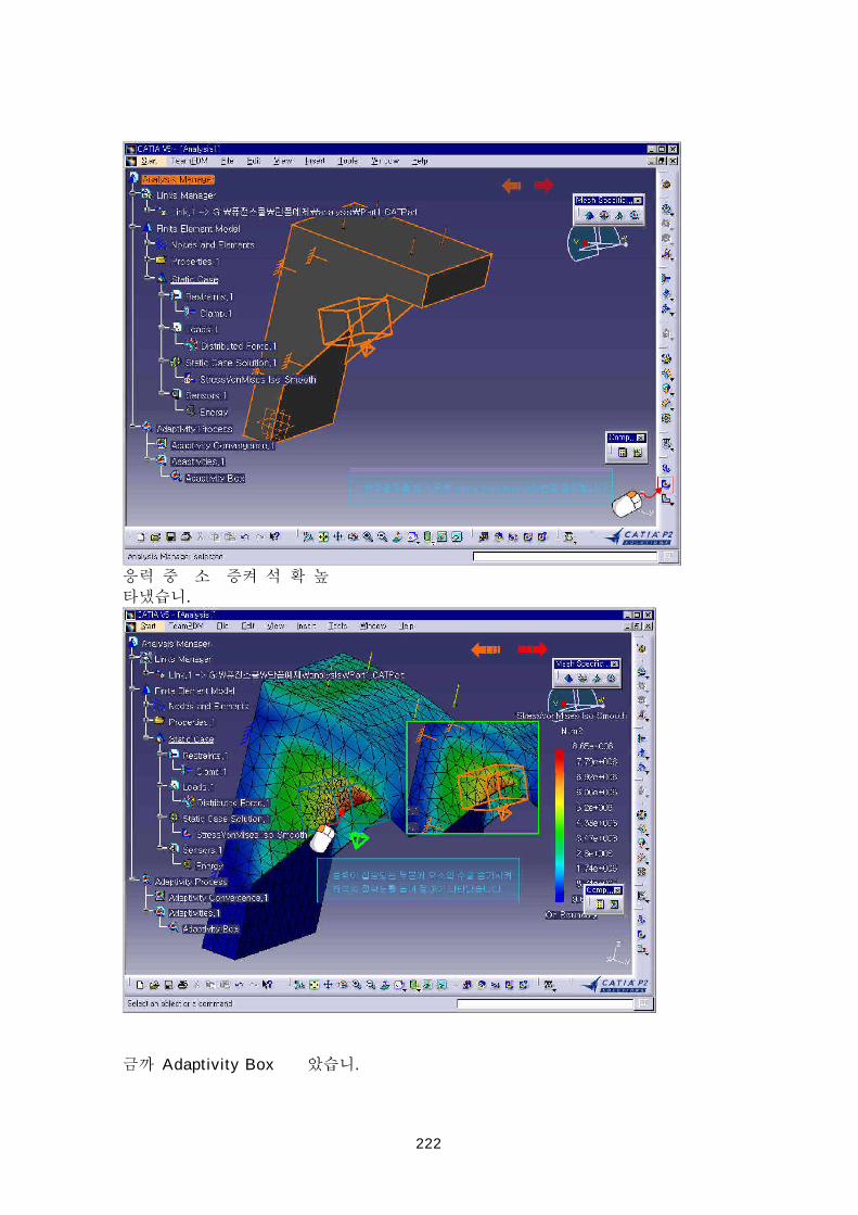
222
.
Adaptivity Box .
223
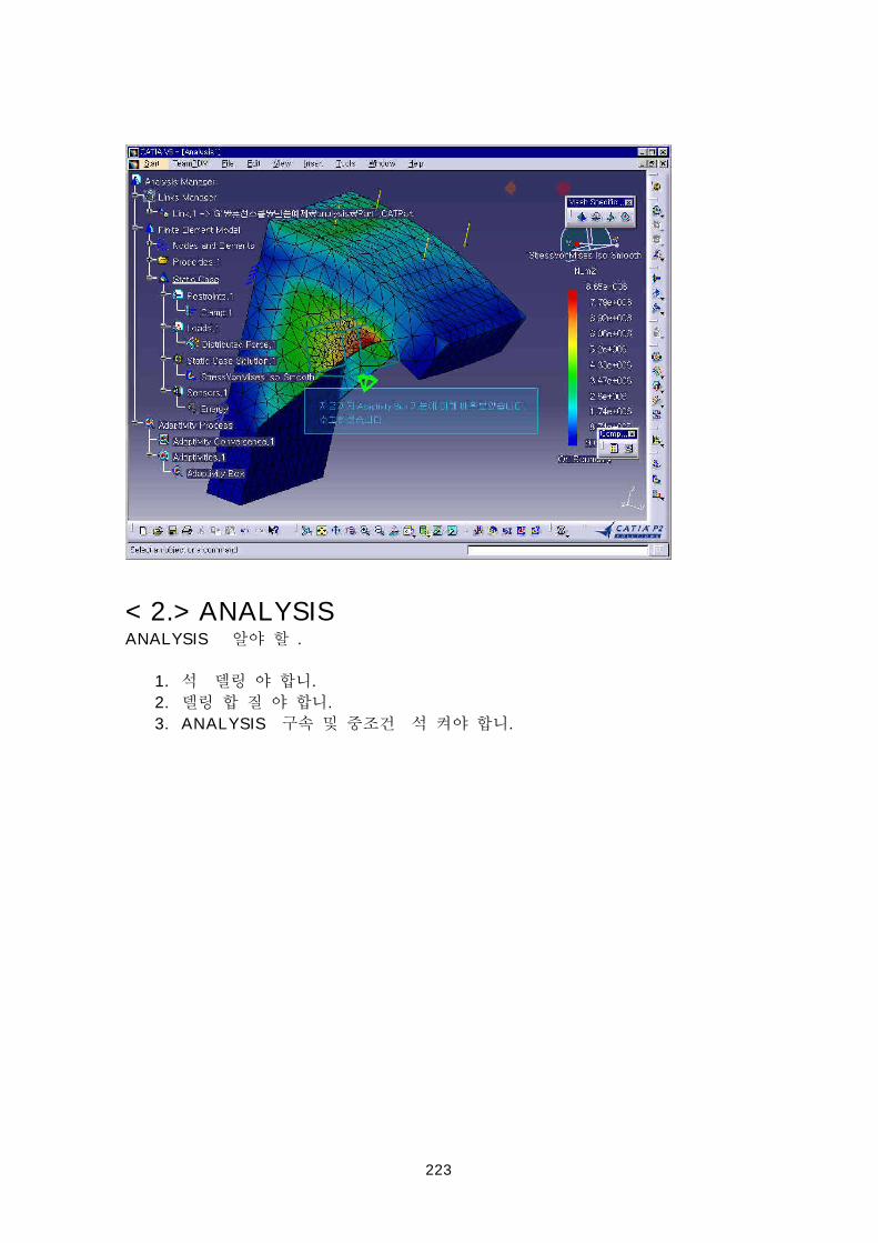
< 2.> ANALYSISANALYSIS .
1. .
2. .
3. ANALYSIS .
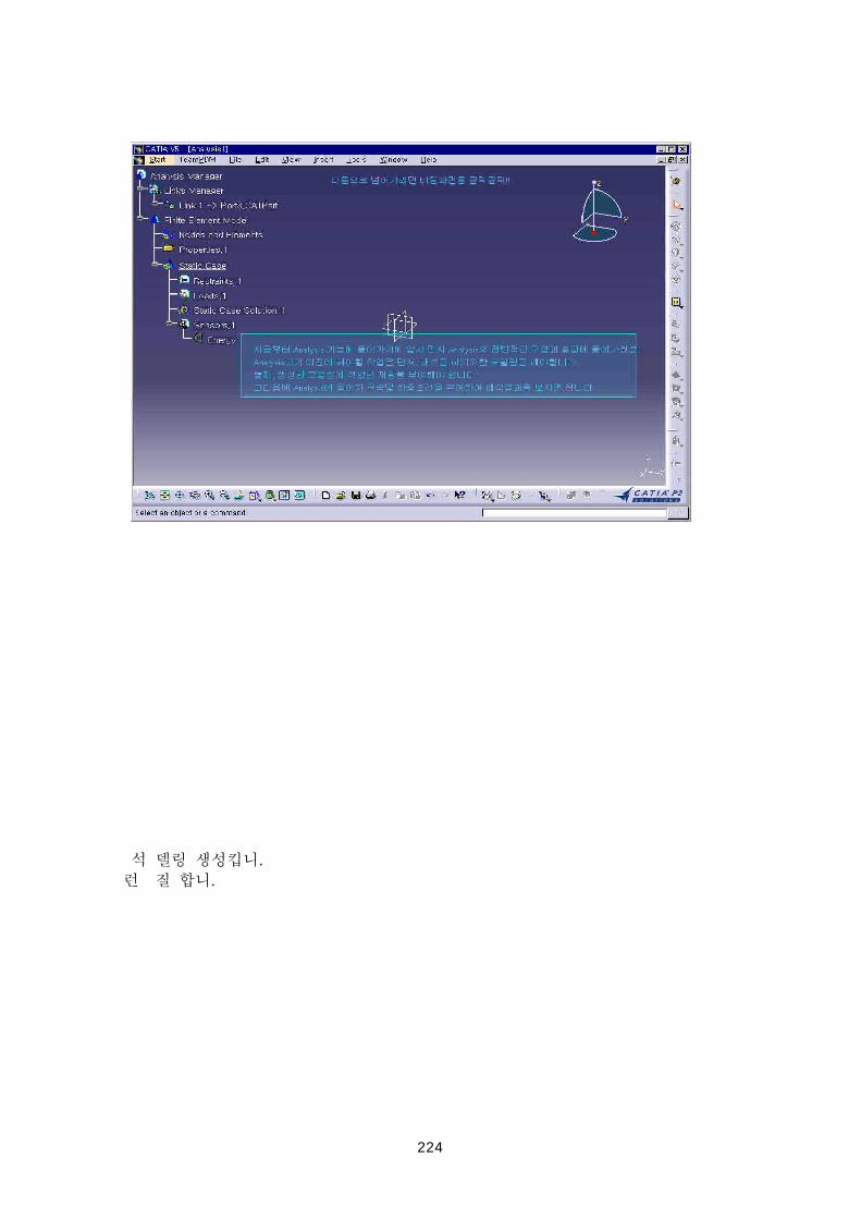
224
.
.
225
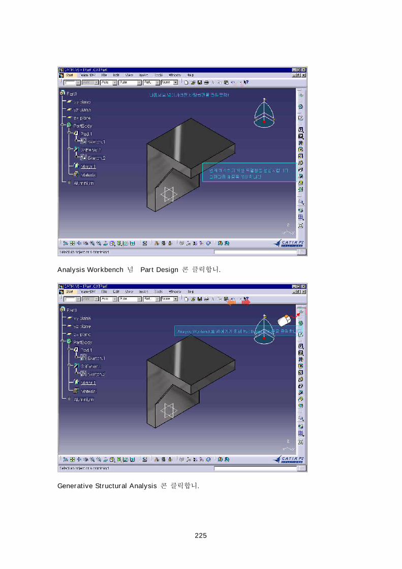
Analysis Workbench Part Design .
Generative Structural Analysis .
226
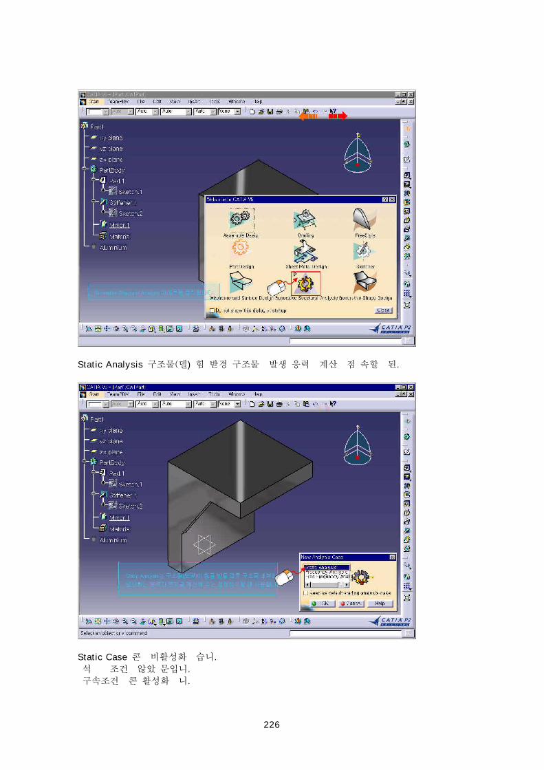
Static Analysis ) .
Static Case .
.
.
227
Clamp .
OK .
228
Force Geometry Virtual Part .
Force .
Force .
229
Supports .
OK .
Compute .
Compute .
230
OK .
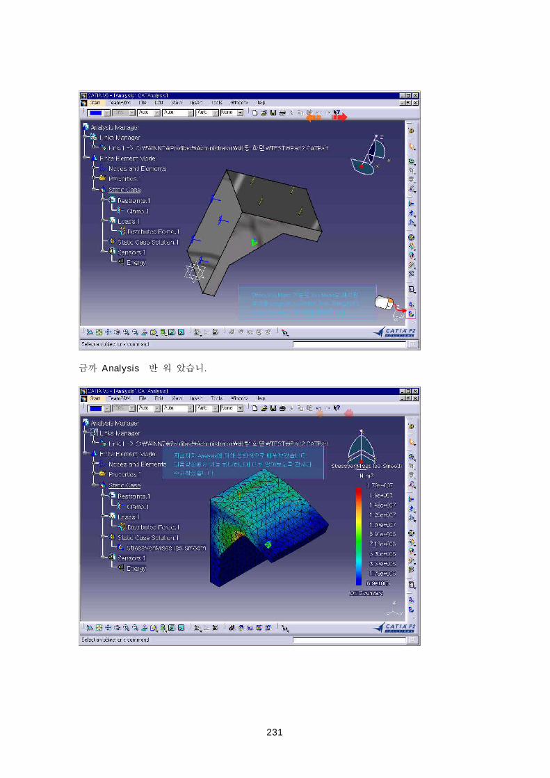
231
Analysis .

232