catia labsheets zeit 1501: engineering practice … · catia labsheets zeit 1501: engineering...
TRANSCRIPT
CATIA LABSHEETS ZEIT 1501: Engineering Practice and Design
Tapabrata RayHemant Kumar Singh
Khairul Alam
2014

Important Information on CATIA Drawing Submissions: 2014
Please take note of the following: (a) Please save your drawing frequently. Be aware of CATIA crashes and unfinished drawings cannot
be assessed. (b) Please make sure you sign against your name each class you come in. (c) The tutors will be collecting your CATIA drawings on their USB Drive at the end of each session. (d) The name of the file should be “T1_z3314312.CATPart” for a student with id z3314312 for
Tutorial 1 submission. For tutorials which have part A, B and C, they would be names as “T1A_z3314312.CATPart” and so on.
(e) Refer to “Setting Up” for setting up CATIA. (f) Please refrain from jumping across groups and be on time for the classes.
Setting Up
1. Start-up is usually very slow….wait patiently. 2. Menu bar: Tools/Options/Infrastructure/Part Infrastructure/Display …. Display in Specification
Tree, check all buttons ON. 3. Menu bar: Tools/Options/Display/Performance/3D Accuracy and 2D Accuracy set to 0.01. Press
OK to save. 4. Menu bar: Tools/Options/Mechanical Design/Sketcher/Constraint …. Make sure ‘Creates the
geometrical constraints’ and ‘Creates the dimensional constraints’ are checked ON. 5. Create a Folder named as your student (Catia_zID) and put all your files for the tutorial in it
which will be collected at the end of each class. 6. Setting up steps 1-4 need to be done in every Tutorial Class.
Fig. 2: The screen that appears after closing the initial product file while starting CATIA
2
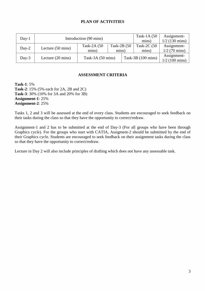
PLAN OF ACTIVITIES
Day-1 Introduction (90 mins) Task-1A (50 mins)
Assignment-1/2 (130 mins)
Day-2 Lecture (50 mins) Task-2A (50 mins)
Task-2B (50 mins)
Task-2C (50 mins)
Assignment-1/2 (70 mins)
Day-3 Lecture (20 mins) Task-3A (50 mins) Task-3B (100 mins) Assignment-1/2 (100 mins)
ASSESSMENT CRITERIA Task-1: 5% Task-2: 15% (5% each for 2A, 2B and 2C) Task-3: 30% (10% for 3A and 20% for 3B) Assignment-1: 25% Assignment-2: 25% Tasks 1, 2 and 3 will be assessed at the end of every class. Students are encouraged to seek feedback on their tasks during the class so that they have the opportunity to correct/redraw. Assignment-1 and 2 has to be submitted at the end of Day-3 (For all groups who have been through Graphics cycle). For the groups who start with CATIA, Assigment-2 should be submitted by the end of their Graphics cycle. Students are encouraged to seek feedback on their assignment tasks during the class so that they have the opportunity to correct/redraw. Lecture in Day 2 will also include principles of drafting which does not have any assessable task.
3
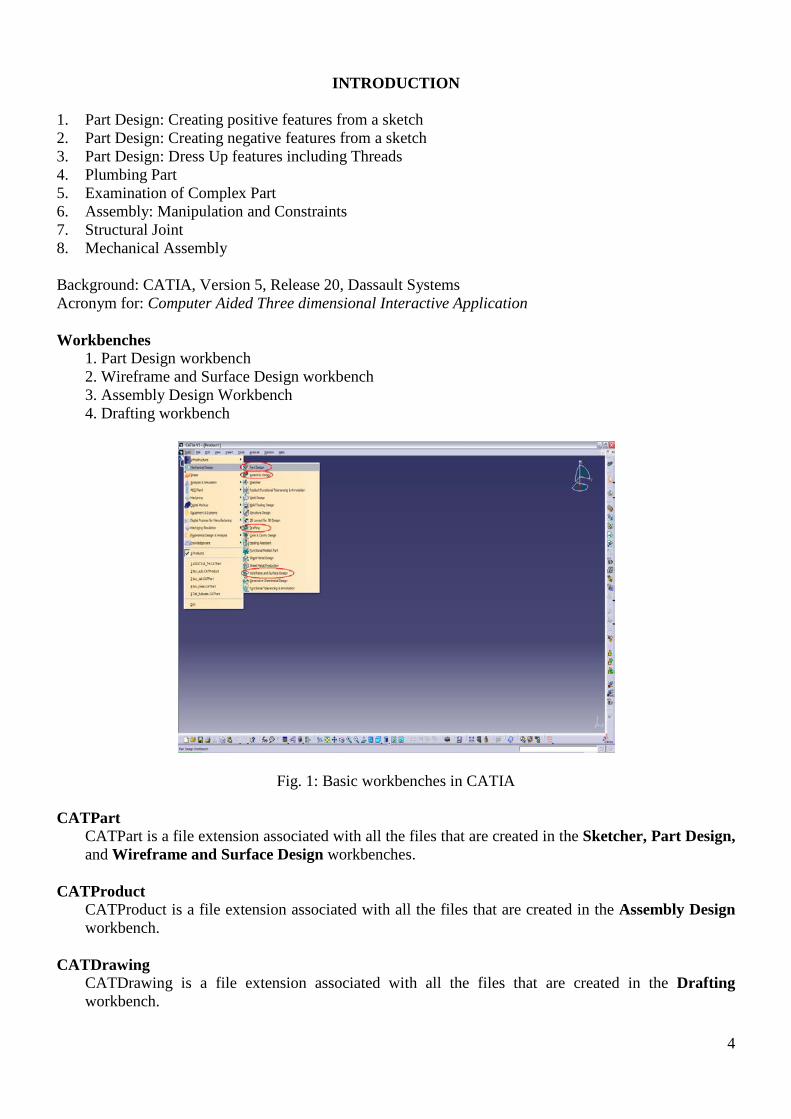
INTRODUCTION
1. Part Design: Creating positive features from a sketch 2. Part Design: Creating negative features from a sketch 3. Part Design: Dress Up features including Threads 4. Plumbing Part 5. Examination of Complex Part 6. Assembly: Manipulation and Constraints 7. Structural Joint 8. Mechanical Assembly Background: CATIA, Version 5, Release 20, Dassault Systems Acronym for: Computer Aided Three dimensional Interactive Application Workbenches
1. Part Design workbench 2. Wireframe and Surface Design workbench 3. Assembly Design Workbench 4. Drafting workbench
Fig. 1: Basic workbenches in CATIA CATPart
CATPart is a file extension associated with all the files that are created in the Sketcher, Part Design, and Wireframe and Surface Design workbenches.
CATProduct
CATProduct is a file extension associated with all the files that are created in the Assembly Design workbench.
CATDrawing
CATDrawing is a file extension associated with all the files that are created in the Drafting workbench.
4
Mouse Operations 1. Select: Left (L) Button Click. For multiple selections hold the CTRL key along with the Left
Button 2. Contextual menu: Right (R) Button Click 3. Object Manipulation: Mouse wheel, alone or in combination with L or R button
- Hold the middle button and move right or left to pan the object - Press the centre and the right and hold to rotate the object - To zoom hold the middle button and the CTRL key
Toolbars 1. Unpack and repack specific toolbars by dragging 2. Expand tools with sub-bars by selecting the black triangle (V) 3. If you accidentally close, restore the toolbars with Menu bar: Tools/Customize/Toolbars/Restore
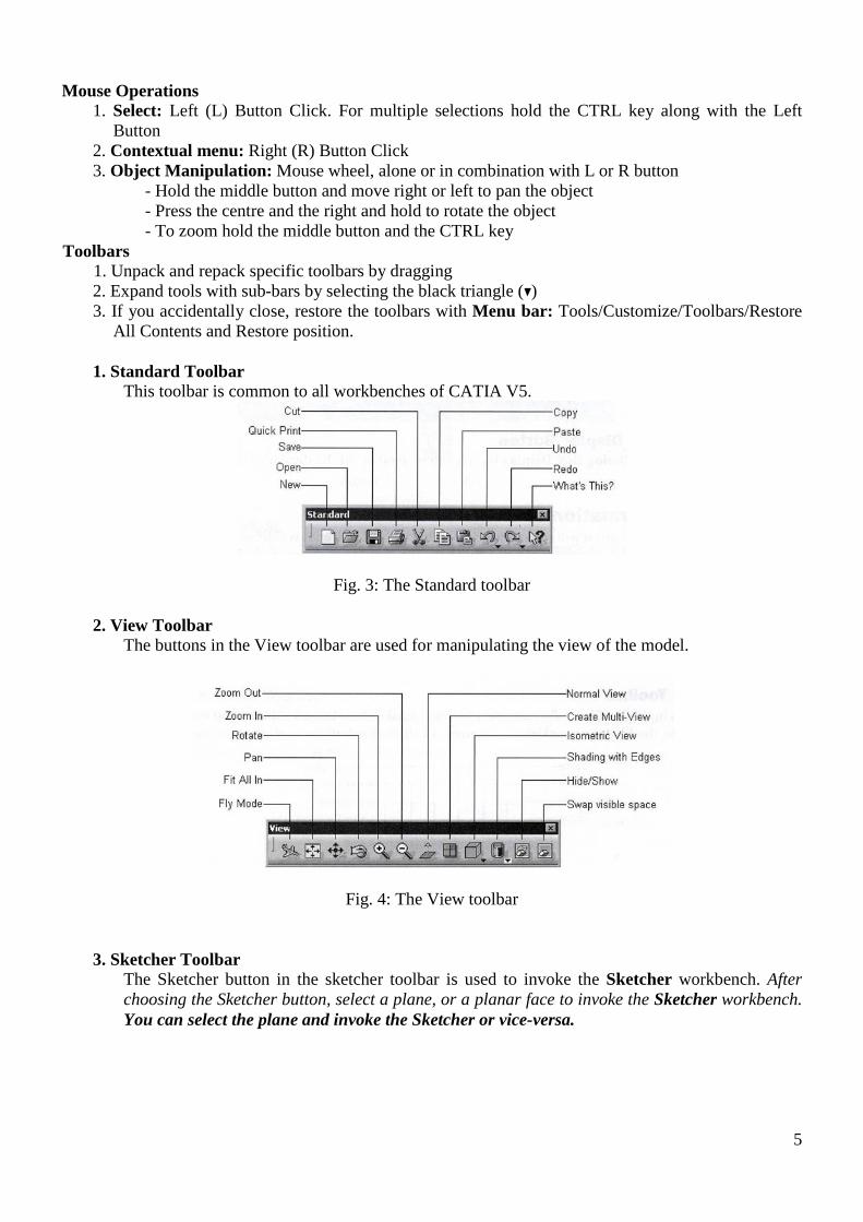
All Contents and Restore position. 1. Standard Toolbar This toolbar is common to all workbenches of CATIA V5.
Fig. 3: The Standard toolbar
2. View Toolbar The buttons in the View toolbar are used for manipulating the view of the model.
Fig. 4: The View toolbar
3. Sketcher Toolbar The Sketcher button in the sketcher toolbar is used to invoke the Sketcher workbench. After
choosing the Sketcher button, select a plane, or a planar face to invoke the Sketcher workbench. You can select the plane and invoke the Sketcher or vice-versa.
5
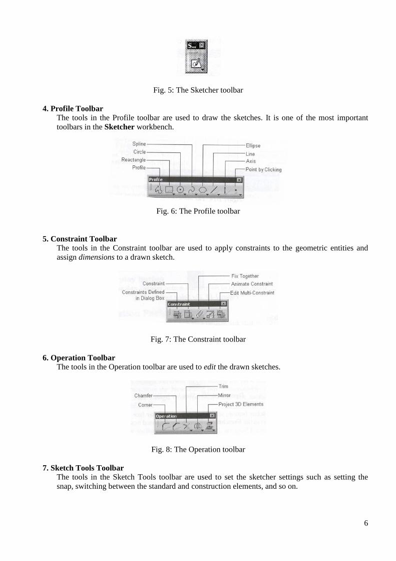
Fig. 5: The Sketcher toolbar
4. Profile Toolbar The tools in the Profile toolbar are used to draw the sketches. It is one of the most important
toolbars in the Sketcher workbench.
Fig. 6: The Profile toolbar
5. Constraint Toolbar The tools in the Constraint toolbar are used to apply constraints to the geometric entities and
assign dimensions to a drawn sketch.
Fig. 7: The Constraint toolbar
6. Operation Toolbar The tools in the Operation toolbar are used to edit the drawn sketches.
Fig. 8: The Operation toolbar
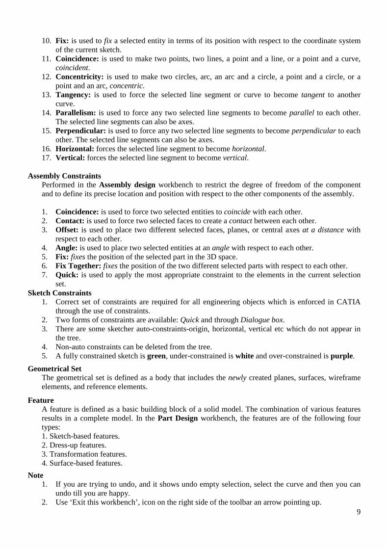
7. Sketch Tools Toolbar The tools in the Sketch Tools toolbar are used to set the sketcher settings such as setting the
snap, switching between the standard and construction elements, and so on.
6
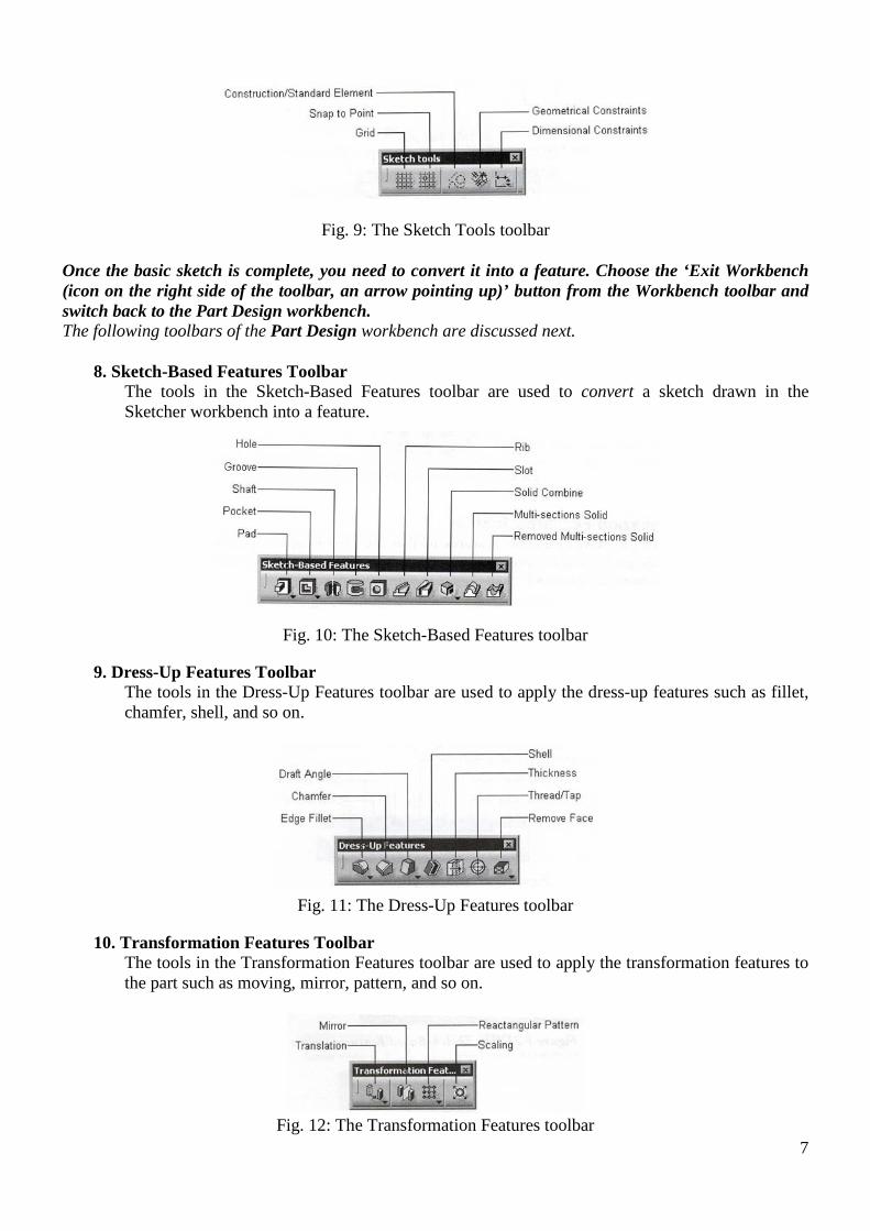
Fig. 9: The Sketch Tools toolbar
Once the basic sketch is complete, you need to convert it into a feature. Choose the ‘Exit Workbench (icon on the right side of the toolbar, an arrow pointing up)’ button from the Workbench toolbar and switch back to the Part Design workbench. The following toolbars of the Part Design workbench are discussed next. 8. Sketch-Based Features Toolbar The tools in the Sketch-Based Features toolbar are used to convert a sketch drawn in the
Sketcher workbench into a feature.
Fig. 10: The Sketch-Based Features toolbar
9. Dress-Up Features Toolbar The tools in the Dress-Up Features toolbar are used to apply the dress-up features such as fillet,
chamfer, shell, and so on.
Fig. 11: The Dress-Up Features toolbar
10. Transformation Features Toolbar The tools in the Transformation Features toolbar are used to apply the transformation features to
the part such as moving, mirror, pattern, and so on.
Fig. 12: The Transformation Features toolbar
7

Specification Tree
The specification tree is a simplified file list. It keeps a track of all the operations that are carried out on the part. You can use the tree to selects parts on the drawing. And you can switch the tree ON and OFF using F3. To increase/decrease the font of the tree: hold the CTRL key and rotate the mouse wheel
Fig. 13: The specification tree that appears on starting a new CATPart file
Compass
The compass is used to manipulate the orientation of parts, assemblies, or sketches. You can also orient the view of the parts and assemblies.
Fig. 14: The compass
Constraints Constraints are the logical operations that are performed on the selected element to define its size and location with respect to the other elements or reference geometries. 1. Geometric constraints, and 2. Assembly constraints
Geometric Constraints
Performed in the Sketcher workbench to define the size and position of a sketched element with respect to the other elements. 1. Distance: is used to apply a distance dimension between any two selected entities. 2. Length: is used to apply a linear dimension to the selected line. 3. Angle: is used to apply an angular dimension between any two selected lines. 4. Radius / Diameter: is used to apply a radius or a diameter to the selected circular entity. 5. Semimajor axis: is used to apply a dimension to the major axis of the selected ellipse. 6. Semiminor axis: is used to apply a dimension to the minor axis of the selected ellipse. 7. Symmetry: is used to force the selected sketched entities symmetrical about an axis. A line
segment can be used as an axis. 8. Midpoint: is used to force a selected point to be placed on the midpoint of the selected line. 9. Equidistant point: is used to force a selected point to be placed at an equal distance from any
two preselected points.
8
10. Fix: is used to fix a selected entity in terms of its position with respect to the coordinate system of the current sketch.
11. Coincidence: is used to make two points, two lines, a point and a line, or a point and a curve, coincident.
12. Concentricity: is used to make two circles, arc, an arc and a circle, a point and a circle, or a point and an arc, concentric.
13. Tangency: is used to force the selected line segment or curve to become tangent to another curve.
14. Parallelism: is used to force any two selected line segments to become parallel to each other. The selected line segments can also be axes.
15. Perpendicular: is used to force any two selected line segments to become perpendicular to each other. The selected line segments can also be axes.
16. Horizontal: forces the selected line segment to become horizontal. 17. Vertical: forces the selected line segment to become vertical.
Assembly Constraints
Performed in the Assembly design workbench to restrict the degree of freedom of the component and to define its precise location and position with respect to the other components of the assembly. 1. Coincidence: is used to force two selected entities to coincide with each other. 2. Contact: is used to force two selected faces to create a contact between each other. 3. Offset: is used to place two different selected faces, planes, or central axes at a distance with
respect to each other. 4. Angle: is used to place two selected entities at an angle with respect to each other. 5. Fix: fixes the position of the selected part in the 3D space. 6. Fix Together: fixes the position of the two different selected parts with respect to each other. 7. Quick: is used to apply the most appropriate constraint to the elements in the current selection
set. Sketch Constraints 1. Correct set of constraints are required for all engineering objects which is enforced in CATIA
through the use of constraints. 2. Two forms of constraints are available: Quick and through Dialogue box. 3. There are some sketcher auto-constraints-origin, horizontal, vertical etc which do not appear in
the tree. 4. Non-auto constraints can be deleted from the tree. 5. A fully constrained sketch is green, under-constrained is white and over-constrained is purple.
Geometrical Set The geometrical set is defined as a body that includes the newly created planes, surfaces, wireframe
elements, and reference elements.
Feature A feature is defined as a basic building block of a solid model. The combination of various features
results in a complete model. In the Part Design workbench, the features are of the following four types:
1. Sketch-based features. 2. Dress-up features. 3. Transformation features. 4. Surface-based features.
Note 1. If you are trying to undo, and it shows undo empty selection, select the curve and then you can
undo till you are happy. 2. Use ‘Exit this workbench’, icon on the right side of the toolbar an arrow pointing up.
9
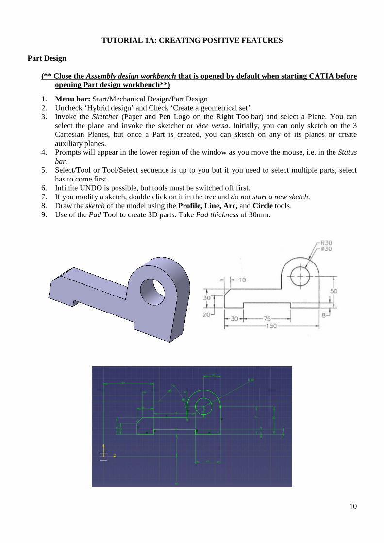
TUTORIAL 1A: CREATING POSITIVE FEATURES
Part Design (** Close the Assembly design workbench that is opened by default when starting CATIA before
opening Part design workbench**)
1. Menu bar: Start/Mechanical Design/Part Design 2. Uncheck ‘Hybrid design’ and Check ‘Create a geometrical set’. 3. Invoke the Sketcher (Paper and Pen Logo on the Right Toolbar) and select a Plane. You can
select the plane and invoke the sketcher or vice versa. Initially, you can only sketch on the 3 Cartesian Planes, but once a Part is created, you can sketch on any of its planes or create auxiliary planes.
4. Prompts will appear in the lower region of the window as you move the mouse, i.e. in the Status bar.
5. Select/Tool or Tool/Select sequence is up to you but if you need to select multiple parts, select has to come first.
6. Infinite UNDO is possible, but tools must be switched off first. 7. If you modify a sketch, double click on it in the tree and do not start a new sketch. 8. Draw the sketch of the model using the Profile, Line, Arc, and Circle tools. 9. Use of the Pad Tool to create 3D parts. Take Pad thickness of 30mm.
10
DRAFTING
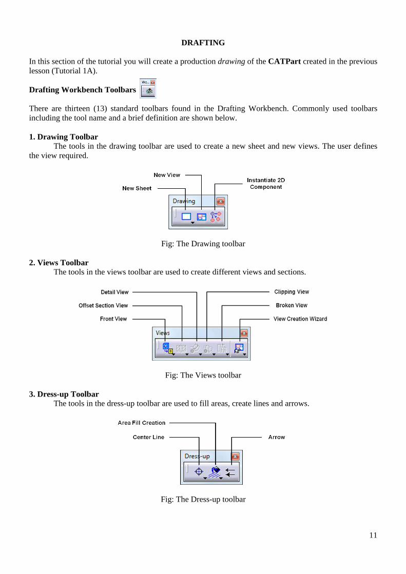
In this section of the tutorial you will create a production drawing of the CATPart created in the previous lesson (Tutorial 1A). Drafting Workbench Toolbars There are thirteen (13) standard toolbars found in the Drafting Workbench. Commonly used toolbars including the tool name and a brief definition are shown below. 1. Drawing Toolbar The tools in the drawing toolbar are used to create a new sheet and new views. The user defines the view required.
Fig: The Drawing toolbar
2. Views Toolbar The tools in the views toolbar are used to create different views and sections.
Fig: The Views toolbar
3. Dress-up Toolbar The tools in the dress-up toolbar are used to fill areas, create lines and arrows.
Fig: The Dress-up toolbar
11

4. Dimensioning Toolbar The tools in the dimensioning toolbar are used to create dimensions.
Fig: The Dimensioning toolbar
5. Dimension Properties Toolbar The tools in the dimension properties toolbar are used to set the dimension line representation and the tolerance on a dimension.
Fig: The Dimension Properties toolbar 6. Annotations Toolbar The tools in the annotations toolbar are used to create text, symbol and table.
Fig: The Annotations toolbar
7. Text Properties Toolbar The tools in the text properties toolbar are used to modify the text and are identical to most Microsoft text products.
Fig: The Text Properties toolbar
12
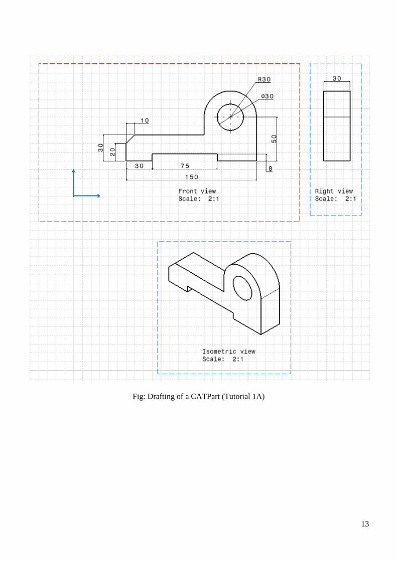
Fig: Drafting of a CATPart (Tutorial 1A)
13
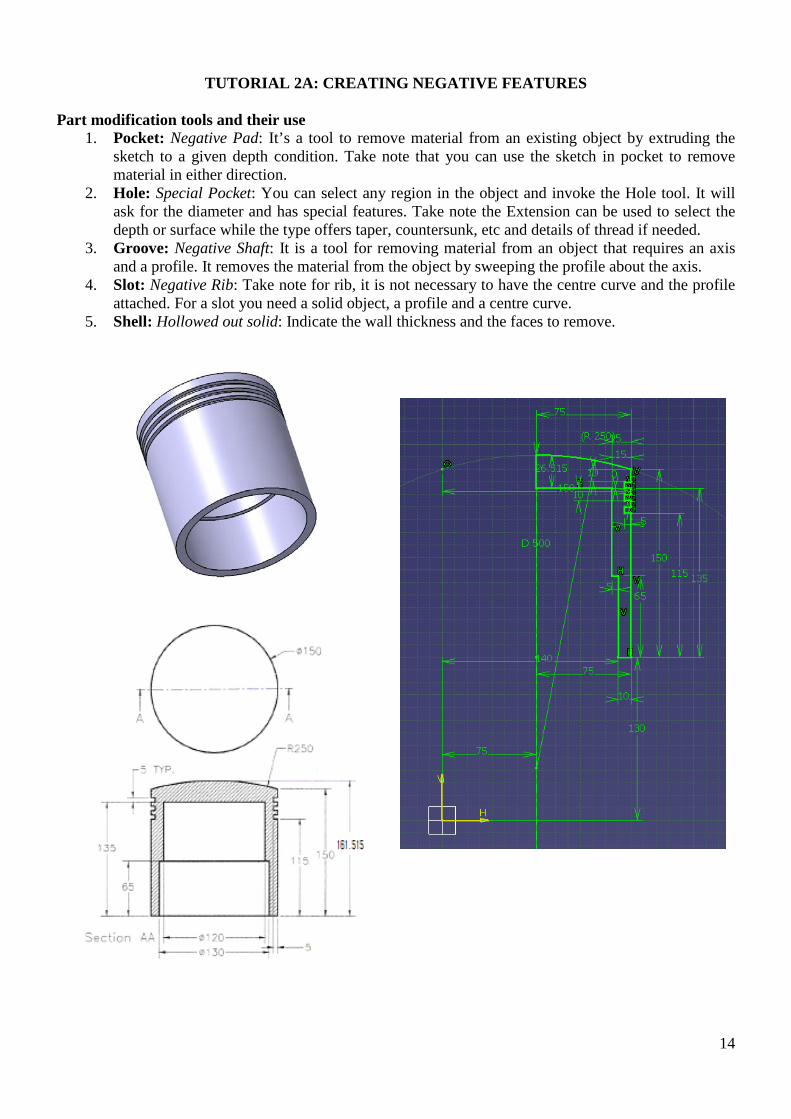
TUTORIAL 2A: CREATING NEGATIVE FEATURES
Part modification tools and their use 1. Pocket: Negative Pad: It’s a tool to remove material from an existing object by extruding the
sketch to a given depth condition. Take note that you can use the sketch in pocket to remove material in either direction.
2. Hole: Special Pocket: You can select any region in the object and invoke the Hole tool. It will ask for the diameter and has special features. Take note the Extension can be used to select the depth or surface while the type offers taper, countersunk, etc and details of thread if needed.
3. Groove: Negative Shaft: It is a tool for removing material from an object that requires an axis and a profile. It removes the material from the object by sweeping the profile about the axis.
4. Slot: Negative Rib: Take note for rib, it is not necessary to have the centre curve and the profile attached. For a slot you need a solid object, a profile and a centre curve.
5. Shell: Hollowed out solid: Indicate the wall thickness and the faces to remove.
14
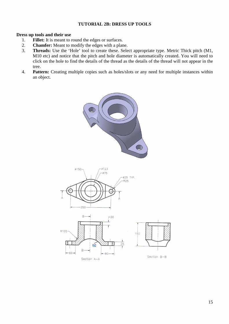
TUTORIAL 2B: DRESS UP TOOLS
Dress up tools and their use 1. Fillet: It is meant to round the edges or surfaces. 2. Chamfer: Meant to modify the edges with a plane. 3. Threads: Use the ‘Hole’ tool to create these. Select appropriate type. Metric Thick pitch (M1,
M10 etc) and notice that the pitch and hole diameter is automatically created. You will need to click on the hole to find the details of the thread as the details of the thread will not appear in the tree.
4. Pattern: Creating multiple copies such as holes/slots or any need for multiple instances within an object.
15
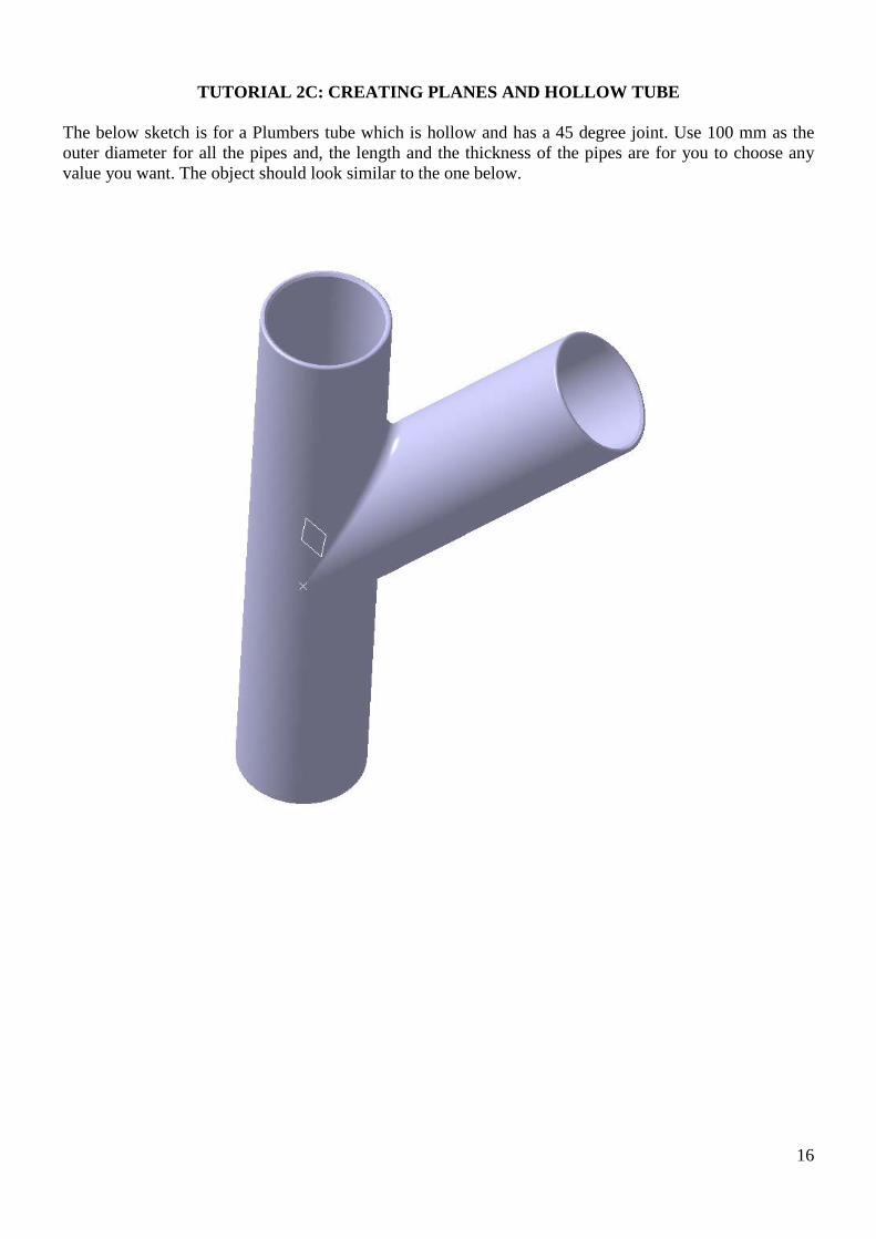
TUTORIAL 2C: CREATING PLANES AND HOLLOW TUBE
The below sketch is for a Plumbers tube which is hollow and has a 45 degree joint. Use 100 mm as the outer diameter for all the pipes and, the length and the thickness of the pipes are for you to choose any value you want. The object should look similar to the one below.
16
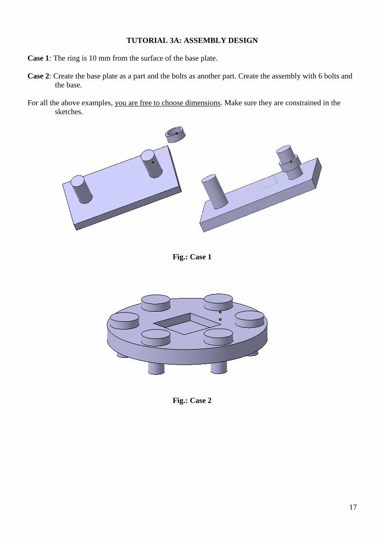
TUTORIAL 3A: ASSEMBLY DESIGN
Case 1: The ring is 10 mm from the surface of the base plate. Case 2: Create the base plate as a part and the bolts as another part. Create the assembly with 6 bolts and
the base. For all the above examples, you are free to choose dimensions. Make sure they are constrained in the
sketches.
Fig.: Case 1
Fig.: Case 2
17
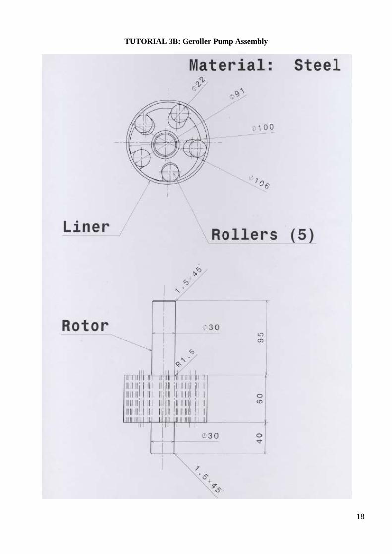
TUTORIAL 3B: Geroller Pump Assembly
18
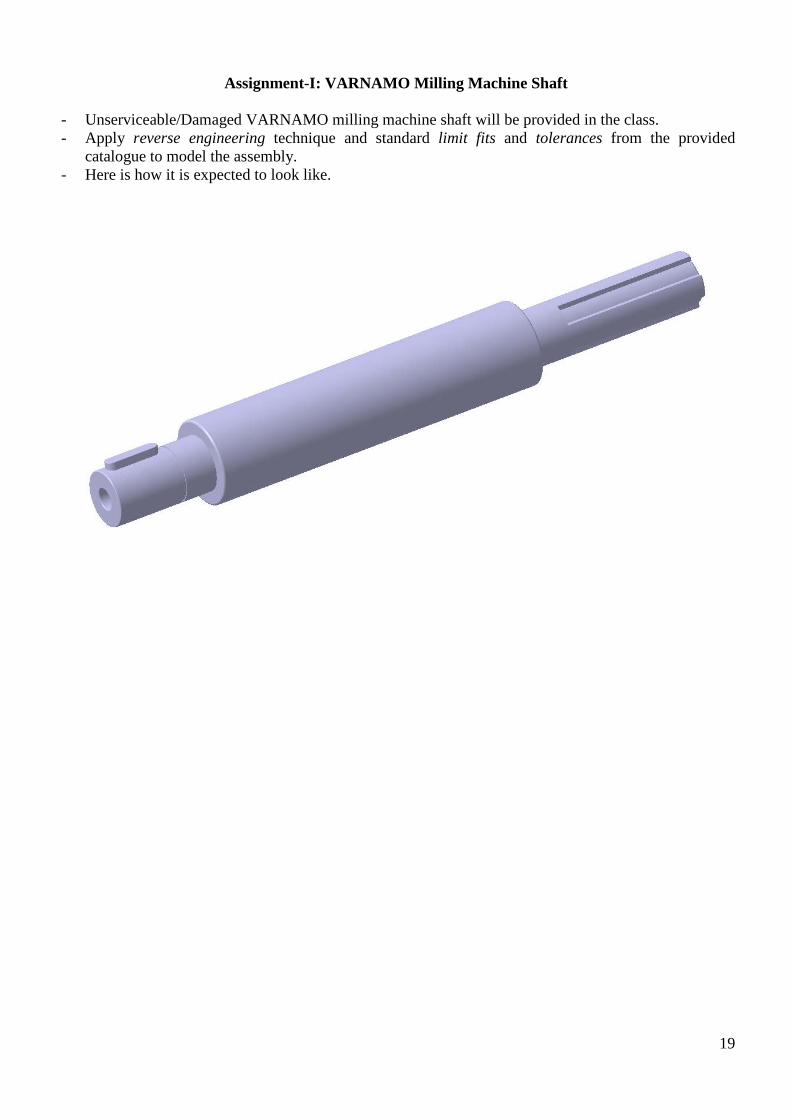
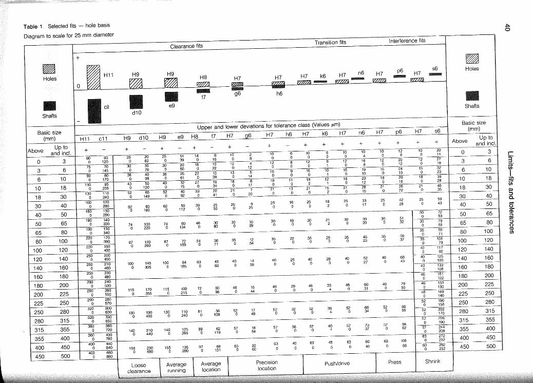
Assignment-I: VARNAMO Milling Machine Shaft
- Unserviceable/Damaged VARNAMO milling machine shaft will be provided in the class. - Apply reverse engineering technique and standard limit fits and tolerances from the provided
catalogue to model the assembly. - Here is how it is expected to look like.
19
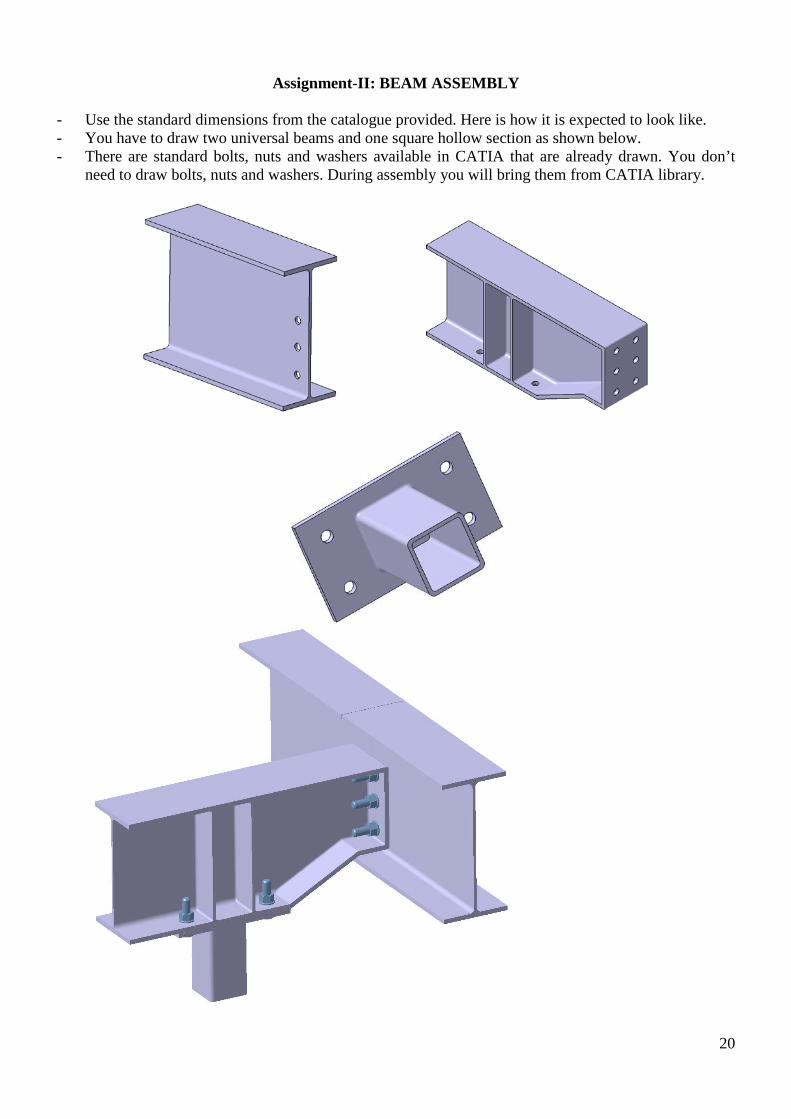
Assignment-II: BEAM ASSEMBLY
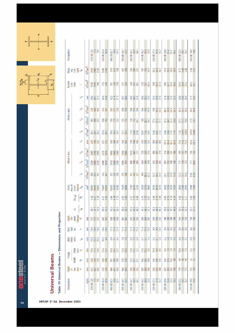
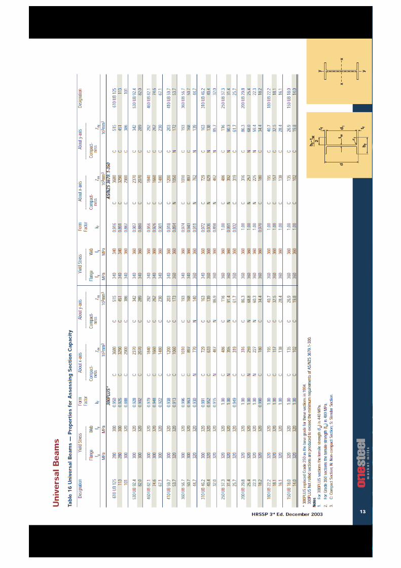
- Use the standard dimensions from the catalogue provided. Here is how it is expected to look like. - You have to draw two universal beams and one square hollow section as shown below. - There are standard bolts, nuts and washers available in CATIA that are already drawn. You don’t
need to draw bolts, nuts and washers. During assembly you will bring them from CATIA library.
20
21
22
Disclaimer: The information on this page has not been checked by an independent person. Use this information at your own risk.ROYMECH
These Pages include various standards. To confirm the status of any standard, identify the replacement standard if it is obsolete and/or purchase the standard please use.BSI Shop
It is also possible to become a BSI member and obtain copies of the Standards at much reduced prices.
HomeSteel Section Index
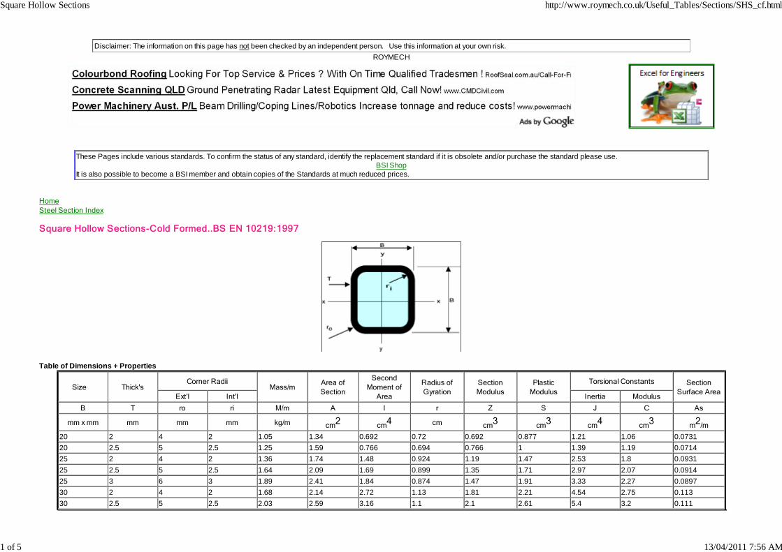
Square Hollow Sections-Cold Formed..BS EN 10219:1997
Table of Dimensions + Properties
Size Thick'sCorner Radii
Mass/mArea ofSection
SecondMoment of
Area
Radius ofGyration
SectionModulus
PlasticModulus
Torsional Constants SectionSurface Area
Ext'l Int'l Inertia Modulus
B T ro ri M/m A I r Z S J C As
mm x mm mm mm mm kg/m cm2 cm4 cm cm3 cm3 cm4 cm3 m2/m
20 2 4 2 1.05 1.34 0.692 0.72 0.692 0.877 1.21 1.06 0.073120 2.5 5 2.5 1.25 1.59 0.766 0.694 0.766 1 1.39 1.19 0.071425 2 4 2 1.36 1.74 1.48 0.924 1.19 1.47 2.53 1.8 0.093125 2.5 5 2.5 1.64 2.09 1.69 0.899 1.35 1.71 2.97 2.07 0.091425 3 6 3 1.89 2.41 1.84 0.874 1.47 1.91 3.33 2.27 0.089730 2 4 2 1.68 2.14 2.72 1.13 1.81 2.21 4.54 2.75 0.11330 2.5 5 2.5 2.03 2.59 3.16 1.1 2.1 2.61 5.4 3.2 0.111
Square Hollow Sections http://www.roymech.co.uk/Useful_Tables/Sections/SHS_cf.html
1 of 5 13/04/2011 7:56 AM
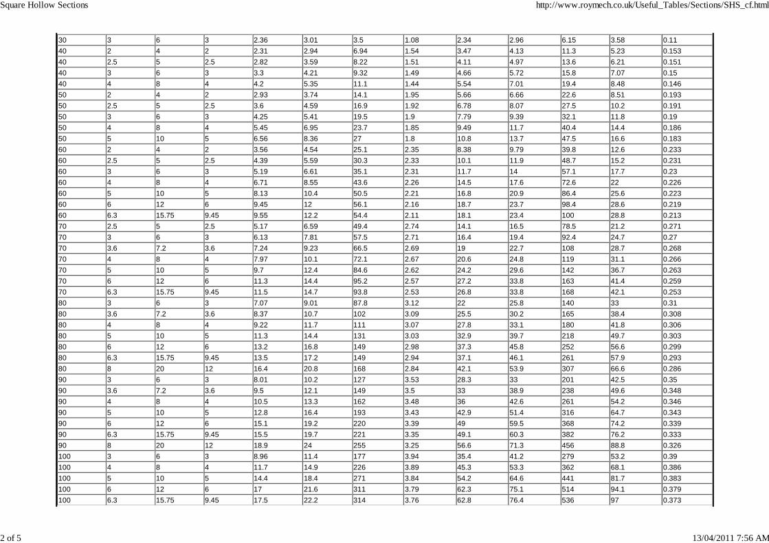
30 3 6 3 2.36 3.01 3.5 1.08 2.34 2.96 6.15 3.58 0.1140 2 4 2 2.31 2.94 6.94 1.54 3.47 4.13 11.3 5.23 0.15340 2.5 5 2.5 2.82 3.59 8.22 1.51 4.11 4.97 13.6 6.21 0.15140 3 6 3 3.3 4.21 9.32 1.49 4.66 5.72 15.8 7.07 0.1540 4 8 4 4.2 5.35 11.1 1.44 5.54 7.01 19.4 8.48 0.14650 2 4 2 2.93 3.74 14.1 1.95 5.66 6.66 22.6 8.51 0.19350 2.5 5 2.5 3.6 4.59 16.9 1.92 6.78 8.07 27.5 10.2 0.19150 3 6 3 4.25 5.41 19.5 1.9 7.79 9.39 32.1 11.8 0.1950 4 8 4 5.45 6.95 23.7 1.85 9.49 11.7 40.4 14.4 0.18650 5 10 5 6.56 8.36 27 1.8 10.8 13.7 47.5 16.6 0.18360 2 4 2 3.56 4.54 25.1 2.35 8.38 9.79 39.8 12.6 0.23360 2.5 5 2.5 4.39 5.59 30.3 2.33 10.1 11.9 48.7 15.2 0.23160 3 6 3 5.19 6.61 35.1 2.31 11.7 14 57.1 17.7 0.2360 4 8 4 6.71 8.55 43.6 2.26 14.5 17.6 72.6 22 0.22660 5 10 5 8.13 10.4 50.5 2.21 16.8 20.9 86.4 25.6 0.22360 6 12 6 9.45 12 56.1 2.16 18.7 23.7 98.4 28.6 0.21960 6.3 15.75 9.45 9.55 12.2 54.4 2.11 18.1 23.4 100 28.8 0.21370 2.5 5 2.5 5.17 6.59 49.4 2.74 14.1 16.5 78.5 21.2 0.27170 3 6 3 6.13 7.81 57.5 2.71 16.4 19.4 92.4 24.7 0.2770 3.6 7.2 3.6 7.24 9.23 66.5 2.69 19 22.7 108 28.7 0.26870 4 8 4 7.97 10.1 72.1 2.67 20.6 24.8 119 31.1 0.26670 5 10 5 9.7 12.4 84.6 2.62 24.2 29.6 142 36.7 0.26370 6 12 6 11.3 14.4 95.2 2.57 27.2 33.8 163 41.4 0.25970 6.3 15.75 9.45 11.5 14.7 93.8 2.53 26.8 33.8 168 42.1 0.25380 3 6 3 7.07 9.01 87.8 3.12 22 25.8 140 33 0.3180 3.6 7.2 3.6 8.37 10.7 102 3.09 25.5 30.2 165 38.4 0.30880 4 8 4 9.22 11.7 111 3.07 27.8 33.1 180 41.8 0.30680 5 10 5 11.3 14.4 131 3.03 32.9 39.7 218 49.7 0.30380 6 12 6 13.2 16.8 149 2.98 37.3 45.8 252 56.6 0.29980 6.3 15.75 9.45 13.5 17.2 149 2.94 37.1 46.1 261 57.9 0.29380 8 20 12 16.4 20.8 168 2.84 42.1 53.9 307 66.6 0.28690 3 6 3 8.01 10.2 127 3.53 28.3 33 201 42.5 0.3590 3.6 7.2 3.6 9.5 12.1 149 3.5 33 38.9 238 49.6 0.34890 4 8 4 10.5 13.3 162 3.48 36 42.6 261 54.2 0.34690 5 10 5 12.8 16.4 193 3.43 42.9 51.4 316 64.7 0.34390 6 12 6 15.1 19.2 220 3.39 49 59.5 368 74.2 0.33990 6.3 15.75 9.45 15.5 19.7 221 3.35 49.1 60.3 382 76.2 0.33390 8 20 12 18.9 24 255 3.25 56.6 71.3 456 88.8 0.326100 3 6 3 8.96 11.4 177 3.94 35.4 41.2 279 53.2 0.39100 4 8 4 11.7 14.9 226 3.89 45.3 53.3 362 68.1 0.386100 5 10 5 14.4 18.4 271 3.84 54.2 64.6 441 81.7 0.383100 6 12 6 17 21.6 311 3.79 62.3 75.1 514 94.1 0.379100 6.3 15.75 9.45 17.5 22.2 314 3.76 62.8 76.4 536 97 0.373
Square Hollow Sections http://www.roymech.co.uk/Useful_Tables/Sections/SHS_cf.html
2 of 5 13/04/2011 7:56 AM
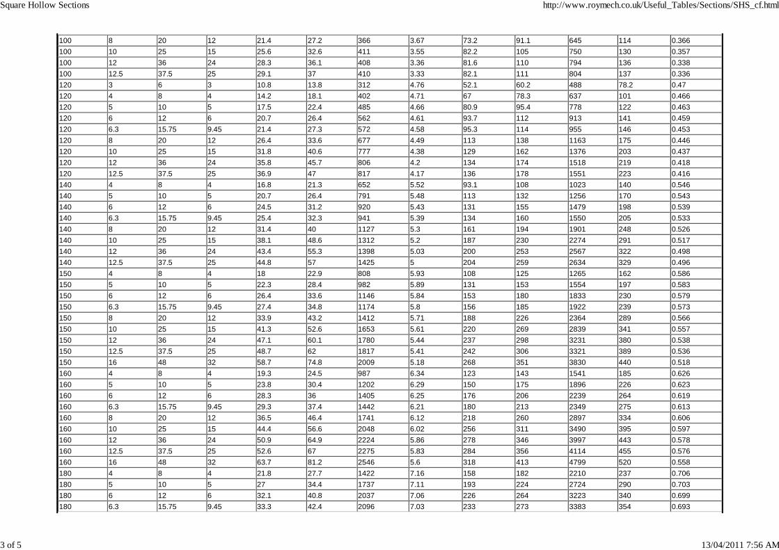
100 8 20 12 21.4 27.2 366 3.67 73.2 91.1 645 114 0.366100 10 25 15 25.6 32.6 411 3.55 82.2 105 750 130 0.357100 12 36 24 28.3 36.1 408 3.36 81.6 110 794 136 0.338100 12.5 37.5 25 29.1 37 410 3.33 82.1 111 804 137 0.336120 3 6 3 10.8 13.8 312 4.76 52.1 60.2 488 78.2 0.47120 4 8 4 14.2 18.1 402 4.71 67 78.3 637 101 0.466120 5 10 5 17.5 22.4 485 4.66 80.9 95.4 778 122 0.463120 6 12 6 20.7 26.4 562 4.61 93.7 112 913 141 0.459120 6.3 15.75 9.45 21.4 27.3 572 4.58 95.3 114 955 146 0.453120 8 20 12 26.4 33.6 677 4.49 113 138 1163 175 0.446120 10 25 15 31.8 40.6 777 4.38 129 162 1376 203 0.437120 12 36 24 35.8 45.7 806 4.2 134 174 1518 219 0.418120 12.5 37.5 25 36.9 47 817 4.17 136 178 1551 223 0.416140 4 8 4 16.8 21.3 652 5.52 93.1 108 1023 140 0.546140 5 10 5 20.7 26.4 791 5.48 113 132 1256 170 0.543140 6 12 6 24.5 31.2 920 5.43 131 155 1479 198 0.539140 6.3 15.75 9.45 25.4 32.3 941 5.39 134 160 1550 205 0.533140 8 20 12 31.4 40 1127 5.3 161 194 1901 248 0.526140 10 25 15 38.1 48.6 1312 5.2 187 230 2274 291 0.517140 12 36 24 43.4 55.3 1398 5.03 200 253 2567 322 0.498140 12.5 37.5 25 44.8 57 1425 5 204 259 2634 329 0.496150 4 8 4 18 22.9 808 5.93 108 125 1265 162 0.586150 5 10 5 22.3 28.4 982 5.89 131 153 1554 197 0.583150 6 12 6 26.4 33.6 1146 5.84 153 180 1833 230 0.579150 6.3 15.75 9.45 27.4 34.8 1174 5.8 156 185 1922 239 0.573150 8 20 12 33.9 43.2 1412 5.71 188 226 2364 289 0.566150 10 25 15 41.3 52.6 1653 5.61 220 269 2839 341 0.557150 12 36 24 47.1 60.1 1780 5.44 237 298 3231 380 0.538150 12.5 37.5 25 48.7 62 1817 5.41 242 306 3321 389 0.536150 16 48 32 58.7 74.8 2009 5.18 268 351 3830 440 0.518160 4 8 4 19.3 24.5 987 6.34 123 143 1541 185 0.626160 5 10 5 23.8 30.4 1202 6.29 150 175 1896 226 0.623160 6 12 6 28.3 36 1405 6.25 176 206 2239 264 0.619160 6.3 15.75 9.45 29.3 37.4 1442 6.21 180 213 2349 275 0.613160 8 20 12 36.5 46.4 1741 6.12 218 260 2897 334 0.606160 10 25 15 44.4 56.6 2048 6.02 256 311 3490 395 0.597160 12 36 24 50.9 64.9 2224 5.86 278 346 3997 443 0.578160 12.5 37.5 25 52.6 67 2275 5.83 284 356 4114 455 0.576160 16 48 32 63.7 81.2 2546 5.6 318 413 4799 520 0.558180 4 8 4 21.8 27.7 1422 7.16 158 182 2210 237 0.706180 5 10 5 27 34.4 1737 7.11 193 224 2724 290 0.703180 6 12 6 32.1 40.8 2037 7.06 226 264 3223 340 0.699180 6.3 15.75 9.45 33.3 42.4 2096 7.03 233 273 3383 354 0.693
Square Hollow Sections http://www.roymech.co.uk/Useful_Tables/Sections/SHS_cf.html
3 of 5 13/04/2011 7:56 AM
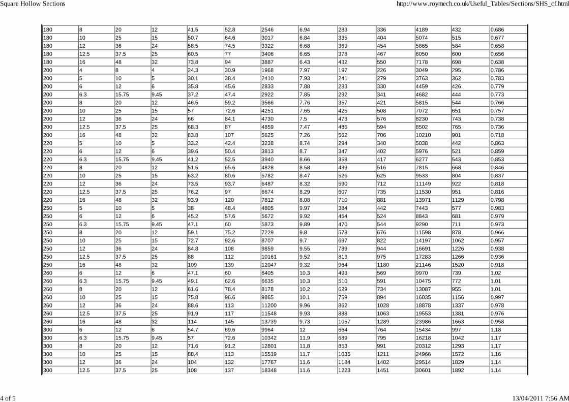
180 8 20 12 41.5 52.8 2546 6.94 283 336 4189 432 0.686180 10 25 15 50.7 64.6 3017 6.84 335 404 5074 515 0.677180 12 36 24 58.5 74.5 3322 6.68 369 454 5865 584 0.658180 12.5 37.5 25 60.5 77 3406 6.65 378 467 6050 600 0.656180 16 48 32 73.8 94 3887 6.43 432 550 7178 698 0.638200 4 8 4 24.3 30.9 1968 7.97 197 226 3049 295 0.786200 5 10 5 30.1 38.4 2410 7.93 241 279 3763 362 0.783200 6 12 6 35.8 45.6 2833 7.88 283 330 4459 426 0.779200 6.3 15.75 9.45 37.2 47.4 2922 7.85 292 341 4682 444 0.773200 8 20 12 46.5 59.2 3566 7.76 357 421 5815 544 0.766200 10 25 15 57 72.6 4251 7.65 425 508 7072 651 0.757200 12 36 24 66 84.1 4730 7.5 473 576 8230 743 0.738200 12.5 37.5 25 68.3 87 4859 7.47 486 594 8502 765 0.736200 16 48 32 83.8 107 5625 7.26 562 706 10210 901 0.718220 5 10 5 33.2 42.4 3238 8.74 294 340 5038 442 0.863220 6 12 6 39.6 50.4 3813 8.7 347 402 5976 521 0.859220 6.3 15.75 9.45 41.2 52.5 3940 8.66 358 417 6277 543 0.853220 8 20 12 51.5 65.6 4828 8.58 439 516 7815 668 0.846220 10 25 15 63.2 80.6 5782 8.47 526 625 9533 804 0.837220 12 36 24 73.5 93.7 6487 8.32 590 712 11149 922 0.818220 12.5 37.5 25 76.2 97 6674 8.29 607 735 11530 951 0.816220 16 48 32 93.9 120 7812 8.08 710 881 13971 1129 0.798250 5 10 5 38 48.4 4805 9.97 384 442 7443 577 0.983250 6 12 6 45.2 57.6 5672 9.92 454 524 8843 681 0.979250 6.3 15.75 9.45 47.1 60 5873 9.89 470 544 9290 711 0.973250 8 20 12 59.1 75.2 7229 9.8 578 676 11598 878 0.966250 10 25 15 72.7 92.6 8707 9.7 697 822 14197 1062 0.957250 12 36 24 84.8 108 9859 9.55 789 944 16691 1226 0.938250 12.5 37.5 25 88 112 10161 9.52 813 975 17283 1266 0.936250 16 48 32 109 139 12047 9.32 964 1180 21146 1520 0.918260 6 12 6 47.1 60 6405 10.3 493 569 9970 739 1.02260 6.3 15.75 9.45 49.1 62.6 6635 10.3 510 591 10475 772 1.01260 8 20 12 61.6 78.4 8178 10.2 629 734 13087 955 1.01260 10 25 15 75.8 96.6 9865 10.1 759 894 16035 1156 0.997260 12 36 24 88.6 113 11200 9.96 862 1028 18878 1337 0.978260 12.5 37.5 25 91.9 117 11548 9.93 888 1063 19553 1381 0.976260 16 48 32 114 145 13739 9.73 1057 1289 23986 1663 0.958300 6 12 6 54.7 69.6 9964 12 664 764 15434 997 1.18300 6.3 15.75 9.45 57 72.6 10342 11.9 689 795 16218 1042 1.17300 8 20 12 71.6 91.2 12801 11.8 853 991 20312 1293 1.17300 10 25 15 88.4 113 15519 11.7 1035 1211 24966 1572 1.16300 12 36 24 104 132 17767 11.6 1184 1402 29514 1829 1.14300 12.5 37.5 25 108 137 18348 11.6 1223 1451 30601 1892 1.14
Square Hollow Sections http://www.roymech.co.uk/Useful_Tables/Sections/SHS_cf.html
4 of 5 13/04/2011 7:56 AM
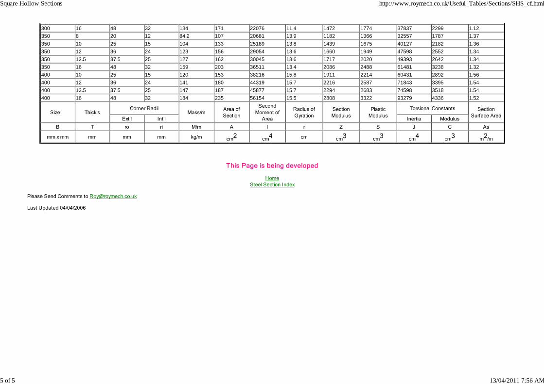
300 16 48 32 134 171 22076 11.4 1472 1774 37837 2299 1.12350 8 20 12 84.2 107 20681 13.9 1182 1366 32557 1787 1.37350 10 25 15 104 133 25189 13.8 1439 1675 40127 2182 1.36350 12 36 24 123 156 29054 13.6 1660 1949 47598 2552 1.34350 12.5 37.5 25 127 162 30045 13.6 1717 2020 49393 2642 1.34350 16 48 32 159 203 36511 13.4 2086 2488 61481 3238 1.32400 10 25 15 120 153 38216 15.8 1911 2214 60431 2892 1.56400 12 36 24 141 180 44319 15.7 2216 2587 71843 3395 1.54400 12.5 37.5 25 147 187 45877 15.7 2294 2683 74598 3518 1.54400 16 48 32 184 235 56154 15.5 2808 3322 93279 4336 1.52
Size Thick'sCorner Radii
Mass/mArea ofSection
SecondMoment of
Area
Radius ofGyration
SectionModulus
PlasticModulus
Torsional Constants SectionSurface Area
Ext'l Int'l Inertia Modulus
B T ro ri M/m A I r Z S J C As
mm x mm mm mm mm kg/m cm2 cm4 cm cm3 cm3 cm4 cm3 m2/m
This Page is being developed
HomeSteel Section Index
Please Send Comments to [email protected]
Last Updated 04/04/2006
Square Hollow Sections http://www.roymech.co.uk/Useful_Tables/Sections/SHS_cf.html
5 of 5 13/04/2011 7:56 AM

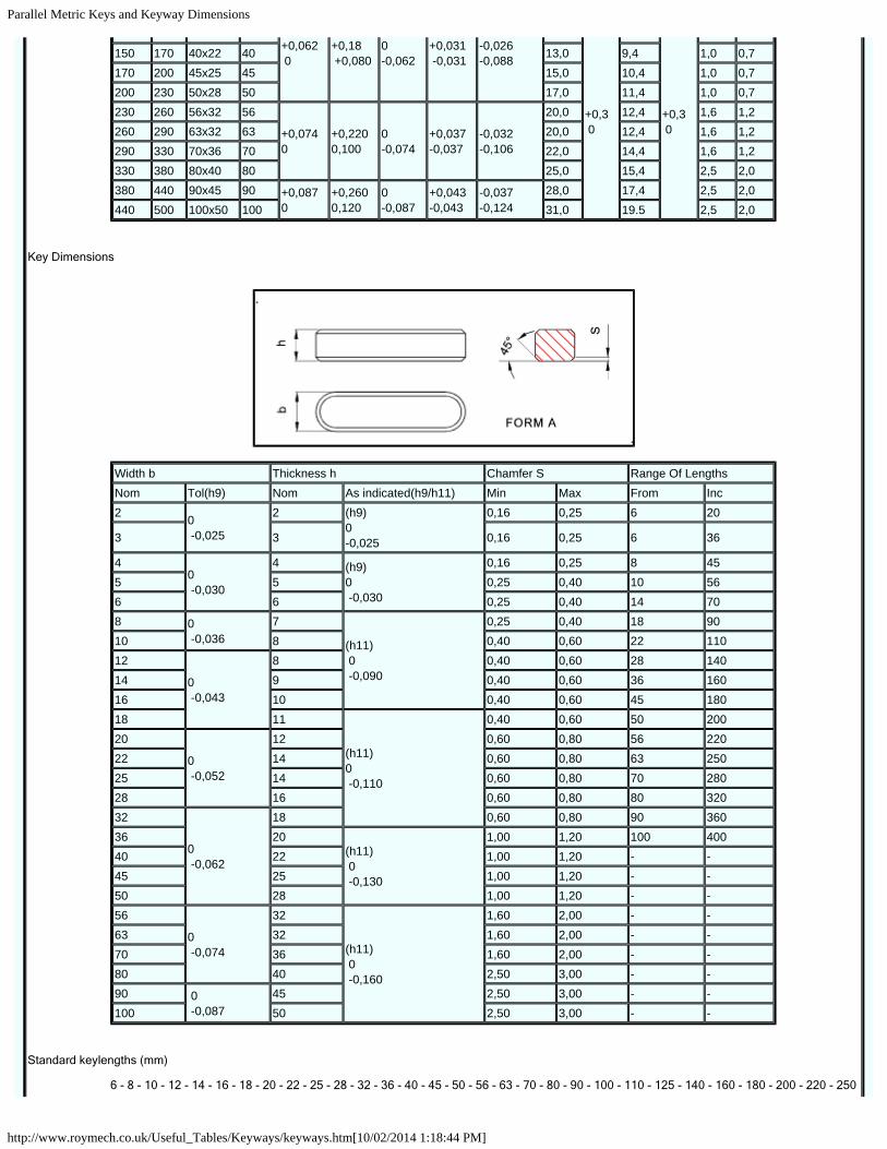
Parallel Metric Keys and Keyway Dimensions
http://www.roymech.co.uk/Useful_Tables/Keyways/keyways.htm[10/02/2014 1:18:44 PM]
Disclaimer: The information on this page has not been checked by an independent person. Use this information at your own risk.ROYMECH
Click arrows to page adverts
These Pages include various standards. To confirm the status of any standard, identify the replacement standard if it is obsolete and/or purchase the standard please use.
BSI Shop It is also possible to become a BSI member and obtain copies of the Standards at much reduced prices.
HomeKeyways Index
Keys and keyway Dimensions
KeyWay /Key Dimensions
keyways /keys dimension in accordance with BS 4235-1:1972: Specification for metric keys and keyways - Parallel and taper keys
Nominal Dia d
Key KeyWay
b x h width x thck
Width b Depth
Radius r
Nom
Tolerance Class Shaft t1 Hub t2
Over InclFree Normal Close/Int - - - -
ShaftH9
HubD10
ShaftN9
HubJs9
Shaft/HubP9 Nom Tol Nom Tol Max min
6 8 2x2 2 +0,025 0
+0,06 +0,02
-0,004-0,029
+0,012-0,012
-0,006 -0,031
1,2
+0,1 0
1,0
+0,1 0
0,16 0,08
8 10 3x3 3 1,8 1,4 0,16 0,08
10 12 4x4 4+0,03 0
+0,078 +0,030
0-0,030
+0,015 -0,015
-0,012-0,042
2,5 1,8 0,16 0,0812 17 5x5 5 3,0 2,3 0,25 0,1617 22 6x6 6 3,5 2,8 0,25 0,1622 30 8x7 8 +0,036
0+0,098 +0,040
0 -0,036
+0,018 -0,018
-0,015 -0,051
4,0 +0,2 0
3,3 +0,2 0
0,25 0,1630 38 10x8 10 5,0 3,3 0,40 0,2538 44 12x8 12
+0,0430
+0,12 +0,050
0 -0,043
+0,021 -0,021
-0,018 -0,061
5,0
+0,2 0
3,3
+0,2 0
0,40 0,2544 50 14x9 14 5,5 3,8 0,40 0,2550 58 16x10 16 6,0 4,3 0,40 0,2558 65 18x11 18 7,0 4,4 0,40 0,2565 75 20x12 20
+0,052 0
+0,149 +0,065
0 -0,052
+0,026 -0,026
-0,022 -0,074
7,5 4,9 0,60 0,4075 85 22x14 22 9,0 5,4 0,60 0,4085 95 25x14 25 9,0 5,4 0,60 0,4095 110 28x16 28 10,0 6,4 0,60 0,40110 130 32x18 32 11,0 7,4 0,6 0,4130 150 36x20 36 12,0 8,4 1,0 0,7
Parallel Metric Keys and Keyway Dimensions
http://www.roymech.co.uk/Useful_Tables/Keyways/keyways.htm[10/02/2014 1:18:44 PM]
+0,062 0
+0,18 +0,080
0 -0,062
+0,031 -0,031
-0,026 -0,088
+0,3 0
+0,3 0
150 170 40x22 40 13,0 9,4 1,0 0,7170 200 45x25 45 15,0 10,4 1,0 0,7200 230 50x28 50 17,0 11,4 1,0 0,7230 260 56x32 56
+0,0740
+0,2200,100
0-0,074
+0,037-0,037
-0,032-0,106
20,0 12,4 1,6 1,2260 290 63x32 63 20,0 12,4 1,6 1,2290 330 70x36 70 22,0 14,4 1,6 1,2330 380 80x40 80 25,0 15,4 2,5 2,0380 440 90x45 90 +0,087
0+0,2600,120
0-0,087
+0,043-0,043
-0,037-0,124
28,0 17,4 2,5 2,0440 500 100x50 100 31,0 19.5 2,5 2,0
Key Dimensions
Width b Thickness h Chamfer S Range Of LengthsNom Tol(h9) Nom As indicated(h9/h11) Min Max From Inc2 0
-0,025
2 (h9)0-0,025
0,16 0,25 6 20
3 3 0,16 0,25 6 36
40 -0,030
4 (h9)0 -0,030
0,16 0,25 8 455 5 0,25 0,40 10 566 6 0,25 0,40 14 708 0
-0,0367
(h11) 0 -0,090
0,25 0,40 18 9010 8 0,40 0,60 22 11012
0 -0,043
8 0,40 0,60 28 14014 9 0,40 0,60 36 16016 10 0,40 0,60 45 18018 11
(h11)0 -0,110
0,40 0,60 50 20020
0 -0,052
12 0,60 0,80 56 22022 14 0,60 0,80 63 25025 14 0,60 0,80 70 28028 16 0,60 0,80 80 32032
0 -0,062
18 0,60 0,80 90 36036 20
(h11) 0 -0,130
1,00 1,20 100 40040 22 1,00 1,20 - -45 25 1,00 1,20 - -50 28 1,00 1,20 - -56
0 -0,074
32
(h11) 0 -0,160
1,60 2,00 - -63 32 1,60 2,00 - -70 36 1,60 2,00 - -80 40 2,50 3,00 - -90 0
-0,08745 2,50 3,00 - -
100 50 2,50 3,00 - -
Standard keylengths (mm)
6 - 8 - 10 - 12 - 14 - 16 - 18 - 20 - 22 - 25 - 28 - 32 - 36 - 40 - 45 - 50 - 56 - 63 - 70 - 80 - 90 - 100 - 110 - 125 - 140 - 160 - 180 - 200 - 220 - 250

Parallel Metric Keys and Keyway Dimensions
http://www.roymech.co.uk/Useful_Tables/Keyways/keyways.htm[10/02/2014 1:18:44 PM]
- 280 - 320 - 360 - 400
b>Links Providing information on Keyways
1. Mitcalc.com...Excel based programme allowing detailed design of shaft connection (19 Eur)2. Hercules -Keyways dimensions ...Download of keyway dimensions3. Specifying Rectangular Keyways ...MDmetric document - useful check information for my tables4. Transeals - Keyways ...Transeals - useful check information for my tables
This Page is being developed
Home Keyways Index
Send Comments to Roy Beardmore
Last Updated 08/04/2012