catia v5 generative drafting · note : in the ..\generative drafting\data directory you can find...
TRANSCRIPT
© 1
997
– 20
01 D
AS
SA
UL
T S
YS
TE
ME
S
Page 1IBM Product Lifecycle Management Solutions / Dassault Systemes
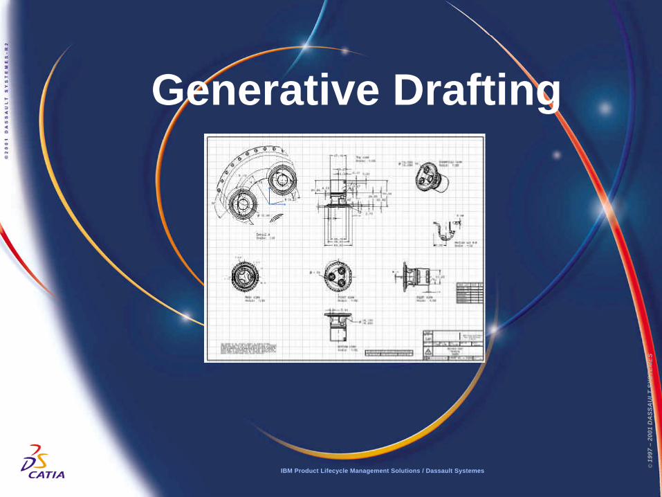
Generative Drafting
IBM Product Lifecycle Management Solutions / Dassault Systemes
© 1
997
– 20
01 D
AS
SA
UL
T S
YS
TE
ME
S
© 1
997
– 20
01 D
AS
SA
UL
T S
YS
TE
ME
S
Page 2IBM Product Lifecycle Management Solutions / Dassault Systemes
Description?This Tutorial is an introduction to Generative Drafting.
Message?To show how CATIA V5 allows the user to automatically generateassociative drafting from 3D mechanical parts produced with CATIA Version5.?To show a higher productive environment for drawings dress-up andannotation
Duration?45 minutes
Product Coverage?Part Design, Generative Drafting
Page 2IBM Product Lifecycle Management Solutions / Dassault Systemes
Tutorial Objectives
© 1
997
– 20
01 D
AS
SA
UL
T S
YS
TE
ME
S
© 1
997
– 20
01 D
AS
SA
UL
T S
YS
TE
ME
S
Page 3IBM Product Lifecycle Management Solutions / Dassault Systemes
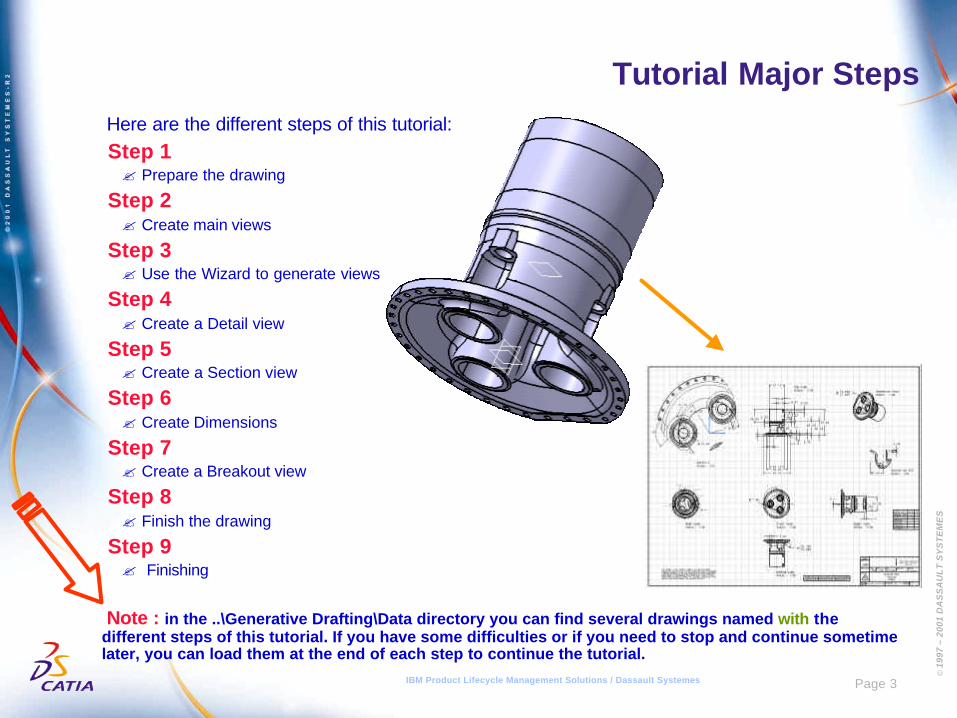
Tutorial Major Steps Here are the different steps of this tutorial: Step 1? Prepare the drawing
Step 2? Create main views
Step 3? Use the Wizard to generate views
Step 4? Create a Detail view
Step 5? Create a Section view
Step 6? Create Dimensions
Step 7? Create a Breakout view
Step 8? Finish the drawing
Step 9? Finishing
Note : in the ..\Generative Drafting\Data directory you can find several drawings named with thedifferent steps of this tutorial. If you have some difficulties or if you need to stop and continue sometimelater, you can load them at the end of each step to continue the tutorial.
© 1
997
– 20
01 D
AS
SA
UL
T S
YS
TE
ME
S
Page 4IBM Product Lifecycle Management Solutions / Dassault Systemes
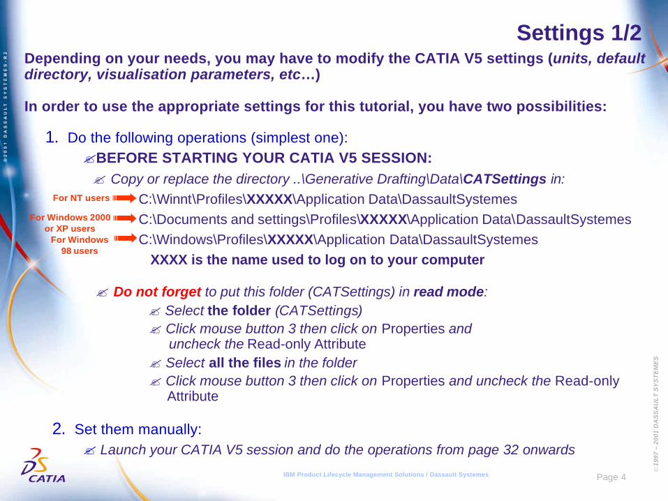
Settings 1/2Depending on your needs, you may have to modify the CATIA V5 settings (units, defaultdirectory, visualisation parameters, etc…)
In order to use the appropriate settings for this tutorial, you have two possibilities:
1. Do the following operations (simplest one):?BEFORE STARTING YOUR CATIA V5 SESSION:? Copy or replace the directory ..\Generative Drafting\Data\CATSettings in:
C:\Winnt\Profiles\XXXXX\Application Data\DassaultSystemesC:\Documents and settings\Profiles\XXXXX\Application Data\DassaultSystemesC:\Windows\Profiles\XXXXX\Application Data\DassaultSystemes XXXX is the name used to log on to your computer
? Do not forget to put this folder (CATSettings) in read mode: ? Select the folder (CATSettings)
? Click mouse button 3 then click on Properties and uncheck the Read-only Attribute? Select all the files in the folder? Click mouse button 3 then click on Properties and uncheck the Read-only
Attribute
2. Set them manually:? Launch your CATIA V5 session and do the operations from page 32 onwards
For NT users
For Windows 2000or XP users
For Windows98 users
© 1
997
– 20
01 D
AS
SA
UL
T S
YS
TE
ME
S
Page 5IBM Product Lifecycle Management Solutions / Dassault Systemes
Settings 2/2
For this tutorial you also need to install a tooling and a material catalogue:? Do not do this step if you have already done it in getting started or in a previous tutorial
? Copy the ..\Getting Started\Catalog.CATMaterial file under ..\ProgramFiles\Dassault Systemes\M07\intel_a\startup\materials\French directory
? Copy the ..\Getting Started\Catalog.CATMaterial file under ..\ProgramFiles\Dassault Systemes\M07\intel_a\startup\materials\German directory
? Copy the ..\Getting Started\Catalog.CATMaterial file under ..\ProgramFiles\Dassault Systemes\M07\intel_a\startup\materials\Japanese directory
? Copy the ..\Getting Started\Catalog.CATMaterial file under ..\ProgramFiles\Dassault Systemes\M07\intel_a\startup\materials directory
? Answer Yes in order to replace the old catalogue
You are now ready to launch your CATIA V5 session
© 1
997
– 20
01 D
AS
SA
UL
T S
YS
TE
ME
S
Page 6IBM Product Lifecycle Management Solutions / Dassault Systemes
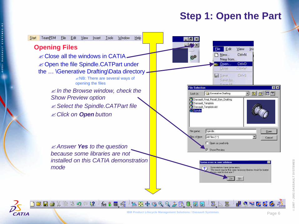
Step 1: Open the Part
Opening Files?Close all the windows in CATIA?Open the file Spindle.CATPart underthe … \Generative Drafting\Data directory
?NB: There are several ways ofopening the files
? In the Browse window, check theShow Preview option?Select the Spindle.CATPart file?Click on Open button
?Answer Yes to the questionbecause some libraries are notinstalled on this CATIA demonstrationmode
© 1
997
– 20
01 D
AS
SA
UL
T S
YS
TE
ME
S
Page 7IBM Product Lifecycle Management Solutions / Dassault Systemes
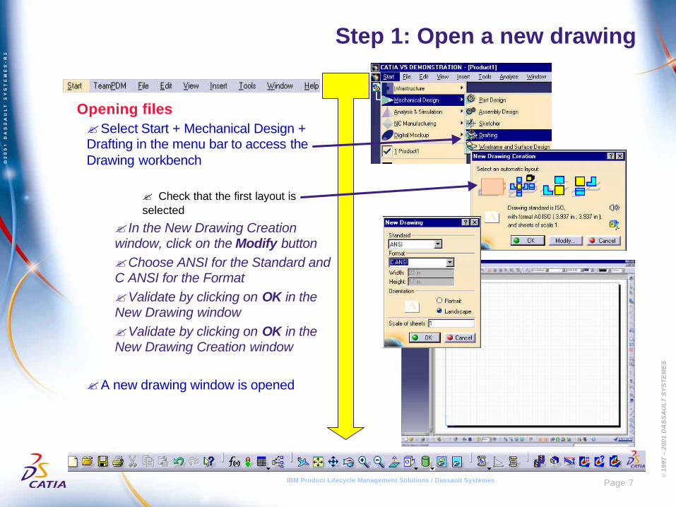
Step 1: Open a new drawing
Opening files?Select Start + Mechanical Design +Drafting in the menu bar to access theDrawing workbench
? Check that the first layout isselected
? In the New Drawing Creationwindow, click on the Modify button?Choose ANSI for the Standard andC ANSI for the Format?Validate by clicking on OK in theNew Drawing window?Validate by clicking on OK in theNew Drawing Creation window
?A new drawing window is opened
© 1
997
– 20
01 D
AS
SA
UL
T S
YS
TE
ME
S
Page 8IBM Product Lifecycle Management Solutions / Dassault Systemes
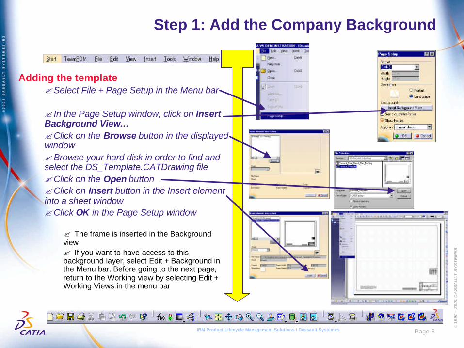
Step 1: Add the Company Background
Adding the template?Select File + Page Setup in the Menu bar
? In the Page Setup window, click on InsertBackground View…?Click on the Browse button in the displayedwindow?Browse your hard disk in order to find andselect the DS_Template.CATDrawing file?Click on the Open button?Click on Insert button in the Insert elementinto a sheet window?Click OK in the Page Setup window
? The frame is inserted in the Backgroundview? If you want to have access to thisbackground layer, select Edit + Background inthe Menu bar. Before going to the next page,return to the Working view by selecting Edit +Working Views in the menu bar
© 1
997
– 20
01 D
AS
SA
UL
T S
YS
TE
ME
S
Page 9IBM Product Lifecycle Management Solutions / Dassault Systemes
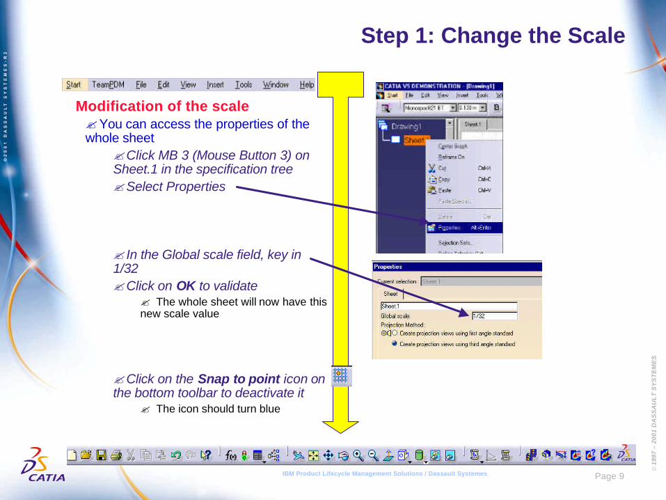
Step 1: Change the Scale
Modification of the scale?You can access the properties of thewhole sheet
?Click MB 3 (Mouse Button 3) onSheet.1 in the specification tree?Select Properties
? In the Global scale field, key in1/32?Click on OK to validate
? The whole sheet will now have thisnew scale value
?Click on the Snap to point icon onthe bottom toolbar to deactivate it
? The icon should turn blue
© 1
997
– 20
01 D
AS
SA
UL
T S
YS
TE
ME
S
Page 10IBM Product Lifecycle Management Solutions / Dassault Systemes
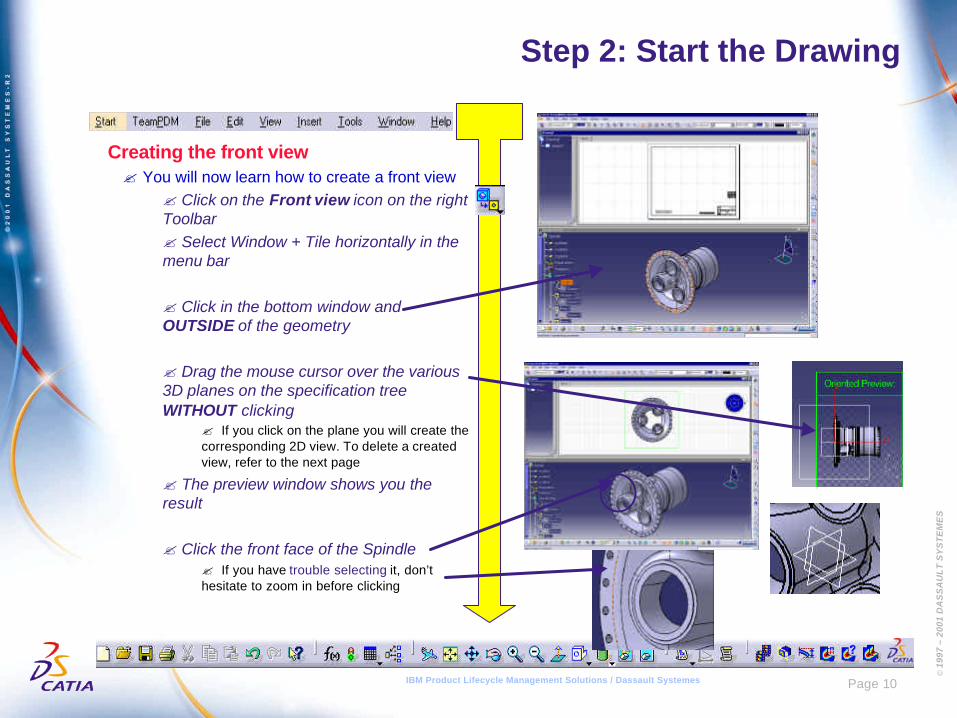
Step 2: Start the Drawing
Creating the front view? You will now learn how to create a front view
? Click on the Front view icon on the rightToolbar? Select Window + Tile horizontally in themenu bar
? Click in the bottom window andOUTSIDE of the geometry
? Drag the mouse cursor over the various3D planes on the specification treeWITHOUT clicking
? If you click on the plane you will create thecorresponding 2D view. To delete a createdview, refer to the next page
? The preview window shows you theresult
? Click the front face of the Spindle? If you have trouble selecting it, don’thesitate to zoom in before clicking
© 1
997
– 20
01 D
AS
SA
UL
T S
YS
TE
ME
S
Page 11IBM Product Lifecycle Management Solutions / Dassault Systemes
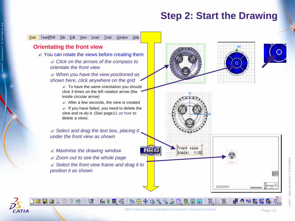
Step 2: Start the Drawing
Orientating the front view? You can rotate the views before creating them
? Click on the arrows of the compass toorientate the front view?When you have the view positioned asshown here, click anywhere on the grid
? To have the same orientation you shouldclick 3 times on the left rotation arrow (theinside circular arrow)? After a few seconds, the view is created? If you have failed, you need to delete theview and re-do it. (See page11 on how todelete a view).
? Select and drag the text box, placing itunder the front view as shown
? Maximise the drawing window? Zoom out to see the whole page? Select the front view frame and drag it toposition it as shown
© 1
997
– 20
01 D
AS
SA
UL
T S
YS
TE
ME
S
Page 12IBM Product Lifecycle Management Solutions / Dassault Systemes
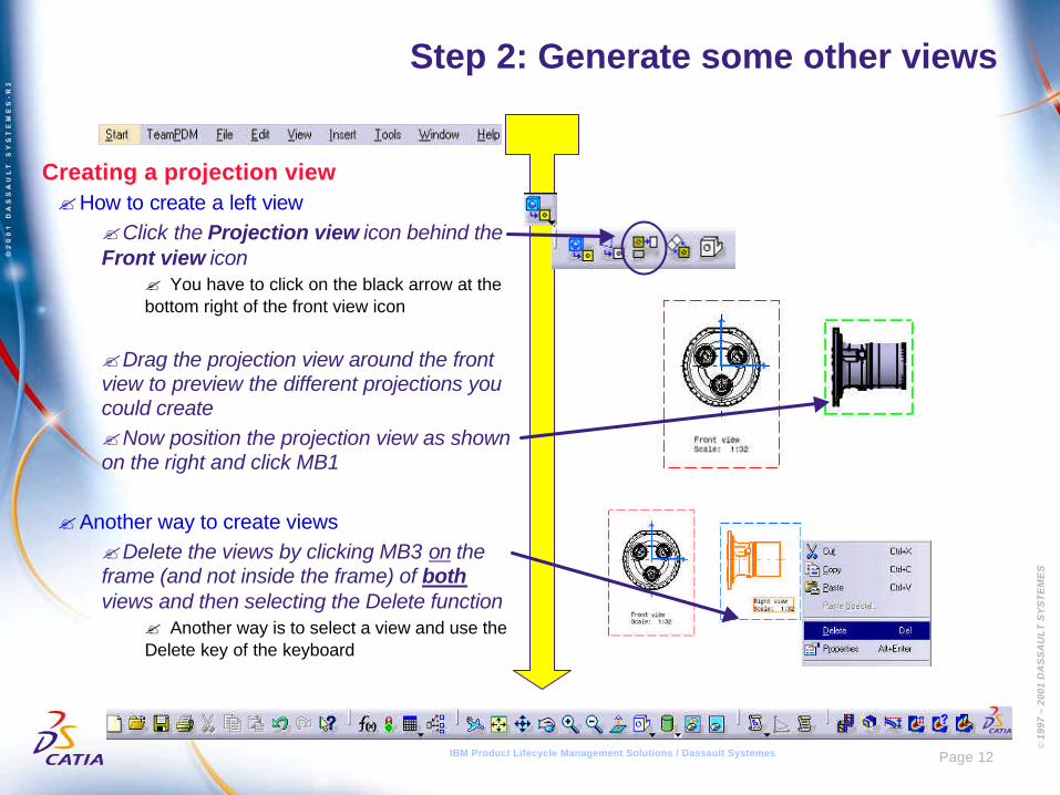
Step 2: Generate some other views
Creating a projection view?How to create a left view
?Click the Projection view icon behind theFront view icon
? You have to click on the black arrow at thebottom right of the front view icon
?Drag the projection view around the frontview to preview the different projections youcould create?Now position the projection view as shownon the right and click MB1
?Another way to create views?Delete the views by clicking MB3 on theframe (and not inside the frame) of bothviews and then selecting the Delete function
? Another way is to select a view and use theDelete key of the keyboard
© 1
997
– 20
01 D
AS
SA
UL
T S
YS
TE
ME
S
Page 13IBM Product Lifecycle Management Solutions / Dassault Systemes
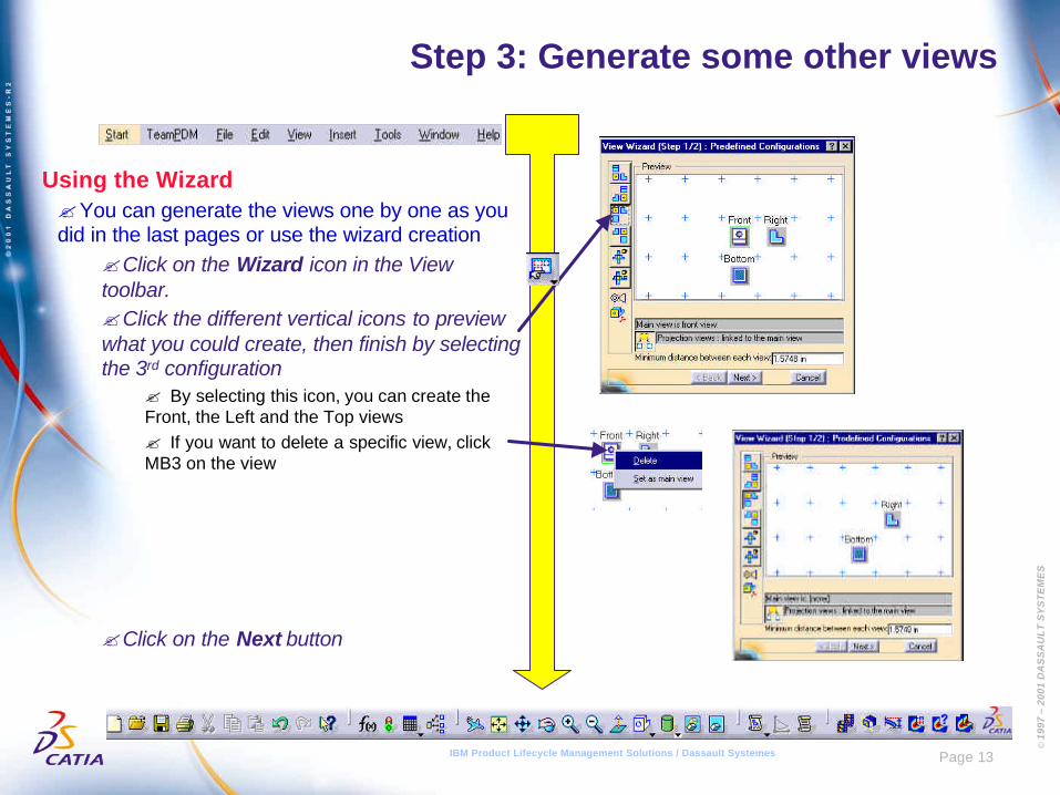
Step 3: Generate some other views
Using the Wizard?You can generate the views one by one as youdid in the last pages or use the wizard creation
?Click on the Wizard icon in the Viewtoolbar.?Click the different vertical icons to previewwhat you could create, then finish by selectingthe 3rd configuration
? By selecting this icon, you can create theFront, the Left and the Top views? If you want to delete a specific view, clickMB3 on the view
?Click on the Next button
© 1
997
– 20
01 D
AS
SA
UL
T S
YS
TE
ME
S
Page 14IBM Product Lifecycle Management Solutions / Dassault Systemes
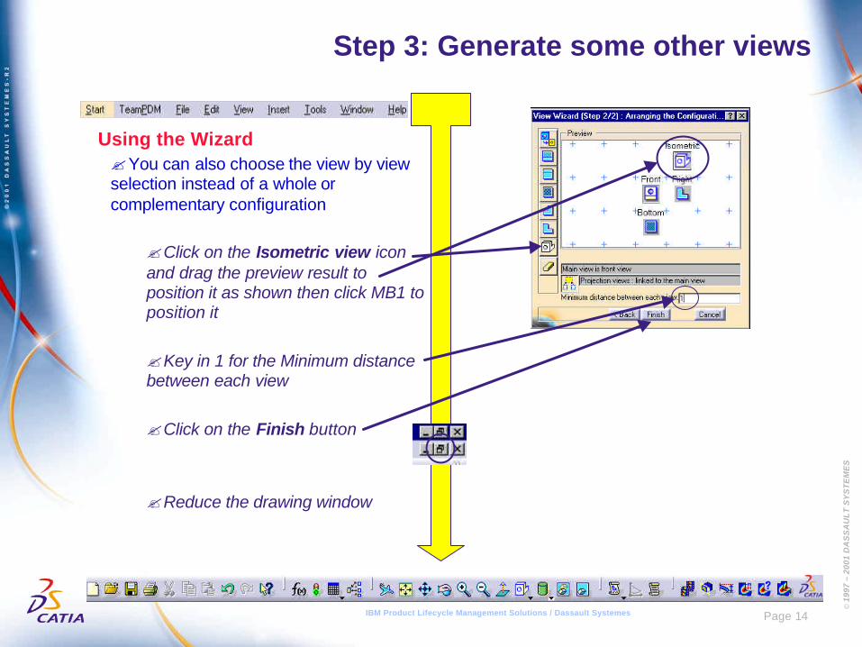
Step 3: Generate some other views
Using the Wizard?You can also choose the view by viewselection instead of a whole orcomplementary configuration
?Click on the Isometric view iconand drag the preview result toposition it as shown then click MB1 toposition it
?Key in 1 for the Minimum distancebetween each view
?Click on the Finish button
?Reduce the drawing window
© 1
997
– 20
01 D
AS
SA
UL
T S
YS
TE
ME
S
Page 15IBM Product Lifecycle Management Solutions / Dassault Systemes
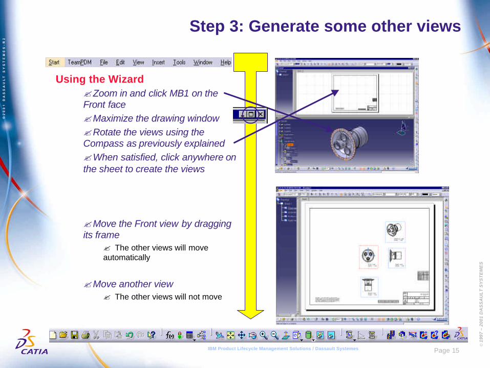
Step 3: Generate some other views
Using the Wizard?Zoom in and click MB1 on theFront face?Maximize the drawing window?Rotate the views using theCompass as previously explained?When satisfied, click anywhere onthe sheet to create the views
?Move the Front view by draggingits frame
? The other views will moveautomatically
?Move another view? The other views will not move
© 1
997
– 20
01 D
AS
SA
UL
T S
YS
TE
ME
S
Page 16IBM Product Lifecycle Management Solutions / Dassault Systemes
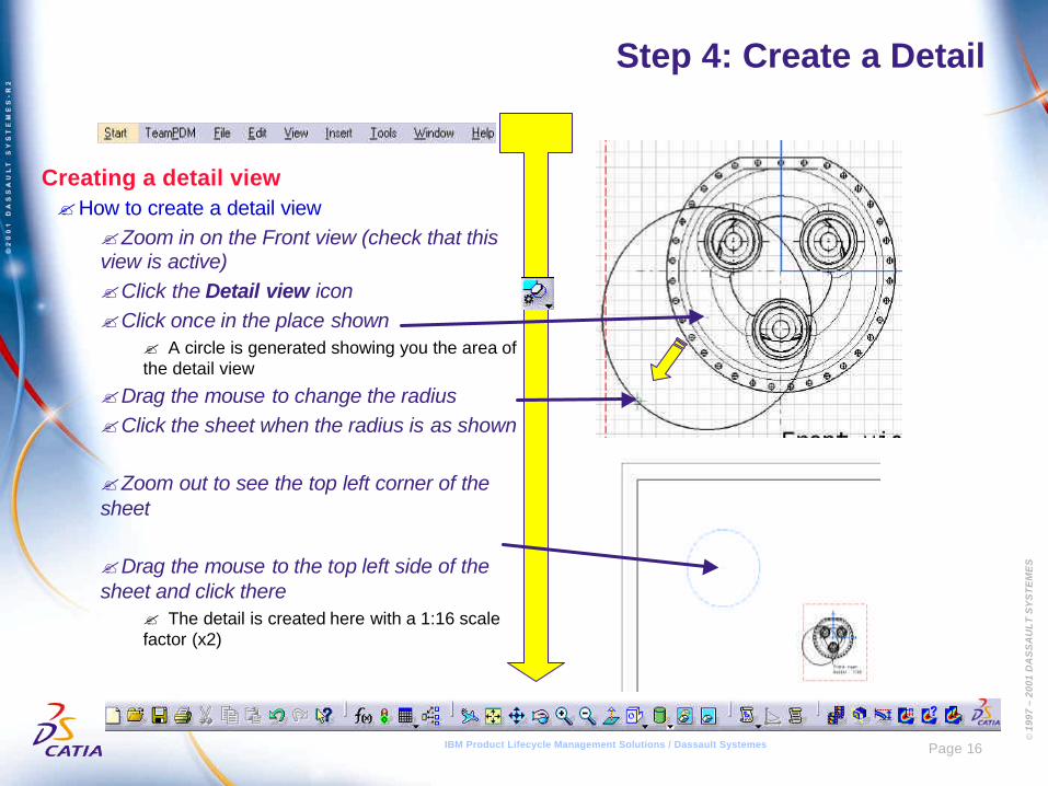
Step 4: Create a Detail
Creating a detail view?How to create a detail view
?Zoom in on the Front view (check that thisview is active)?Click the Detail view icon?Click once in the place shown
? A circle is generated showing you the area ofthe detail view
?Drag the mouse to change the radius?Click the sheet when the radius is as shown
?Zoom out to see the top left corner of thesheet
?Drag the mouse to the top left side of thesheet and click there
? The detail is created here with a 1:16 scalefactor (x2)
© 1
997
– 20
01 D
AS
SA
UL
T S
YS
TE
ME
S
Page 17IBM Product Lifecycle Management Solutions / Dassault Systemes
Step 4: Create a detail
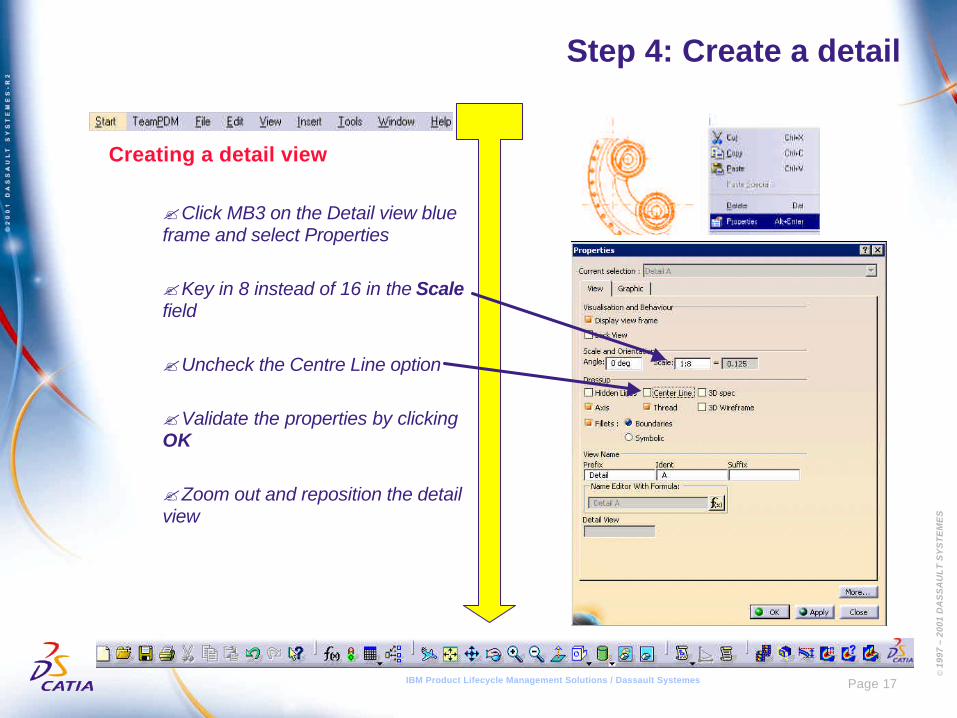
Creating a detail view
?Click MB3 on the Detail view blueframe and select Properties
?Key in 8 instead of 16 in the Scalefield
?Uncheck the Centre Line option
?Validate the properties by clickingOK
?Zoom out and reposition the detailview
© 1
997
– 20
01 D
AS
SA
UL
T S
YS
TE
ME
S
Page 18IBM Product Lifecycle Management Solutions / Dassault Systemes
Step 5: Create a Section
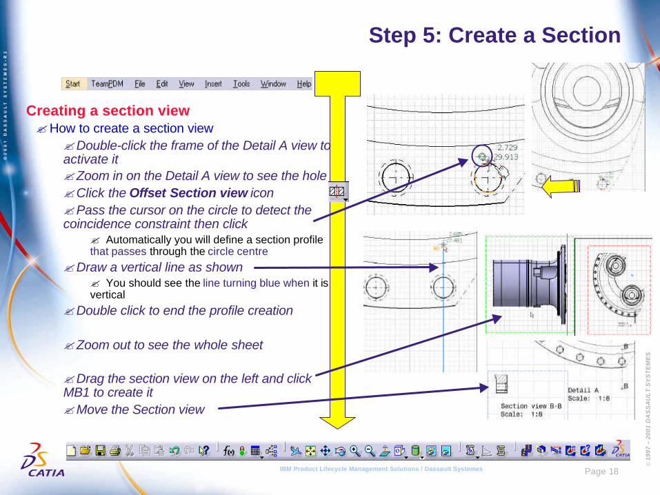
Creating a section view?How to create a section view
?Double-click the frame of the Detail A view toactivate it?Zoom in on the Detail A view to see the hole?Click the Offset Section view icon?Pass the cursor on the circle to detect thecoincidence constraint then click
? Automatically you will define a section profilethat passes through the circle centre
?Draw a vertical line as shown? You should see the line turning blue when it isvertical
?Double click to end the profile creation
?Zoom out to see the whole sheet
?Drag the section view on the left and clickMB1 to create it?Move the Section view
© 1
997
– 20
01 D
AS
SA
UL
T S
YS
TE
ME
S
Page 19IBM Product Lifecycle Management Solutions / Dassault Systemes
Step 6: Create dimensions
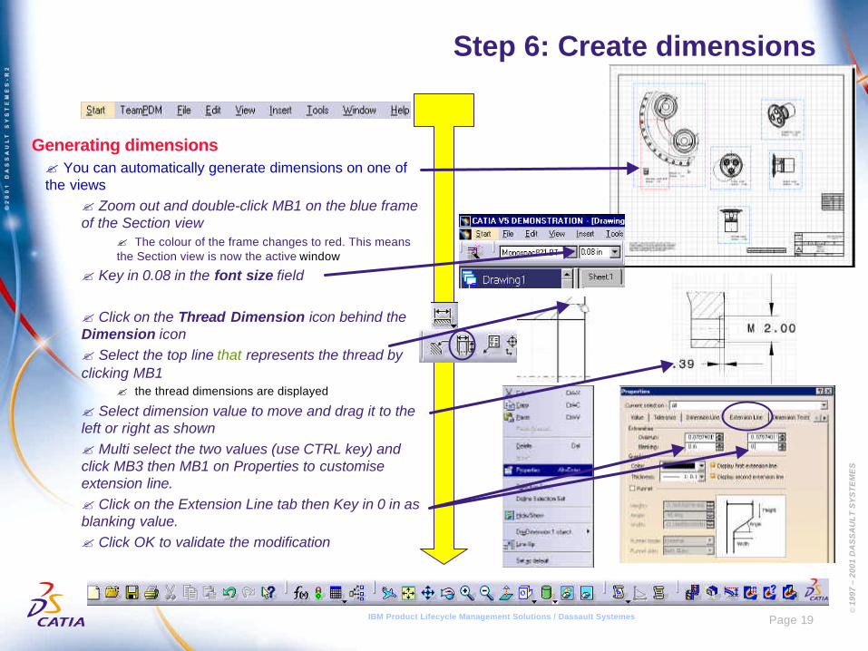
Generating dimensions? You can automatically generate dimensions on one ofthe views
? Zoom out and double-click MB1 on the blue frameof the Section view
? The colour of the frame changes to red. This meansthe Section view is now the active window
? Key in 0.08 in the font size field
? Click on the Thread Dimension icon behind theDimension icon? Select the top line that represents the thread byclicking MB1
? the thread dimensions are displayed
? Select dimension value to move and drag it to theleft or right as shown? Multi select the two values (use CTRL key) andclick MB3 then MB1 on Properties to customiseextension line.? Click on the Extension Line tab then Key in 0 in asblanking value.? Click OK to validate the modification
© 1
997
– 20
01 D
AS
SA
UL
T S
YS
TE
ME
S
Page 20IBM Product Lifecycle Management Solutions / Dassault Systemes
Step 6: Create dimensions
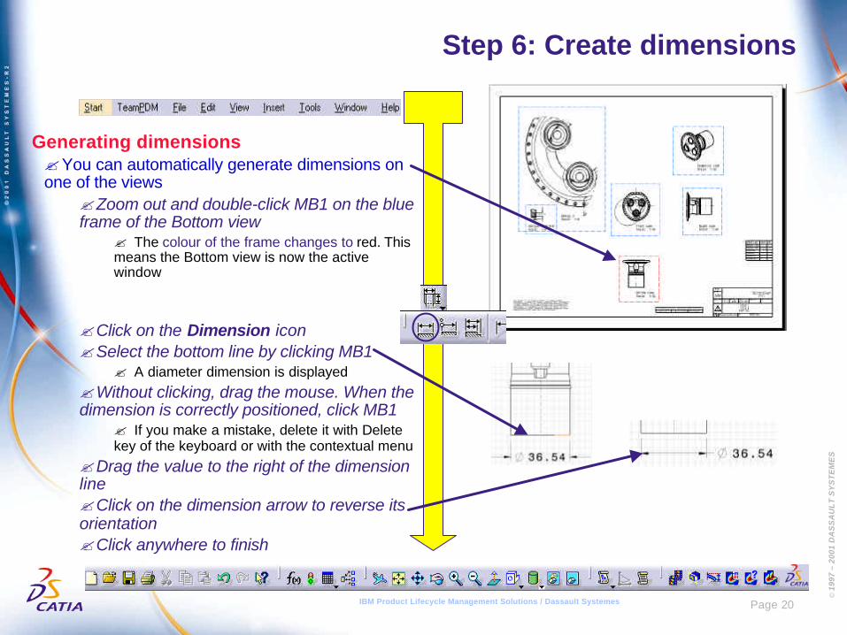
Generating dimensions?You can automatically generate dimensions onone of the views
?Zoom out and double-click MB1 on the blueframe of the Bottom view
? The colour of the frame changes to red. Thismeans the Bottom view is now the activewindow
?Click on the Dimension icon?Select the bottom line by clicking MB1
? A diameter dimension is displayed?Without clicking, drag the mouse. When thedimension is correctly positioned, click MB1
? If you make a mistake, delete it with Deletekey of the keyboard or with the contextual menu
?Drag the value to the right of the dimensionline?Click on the dimension arrow to reverse itsorientation?Click anywhere to finish
© 1
997
– 20
01 D
AS
SA
UL
T S
YS
TE
ME
S
Page 21IBM Product Lifecycle Management Solutions / Dassault Systemes
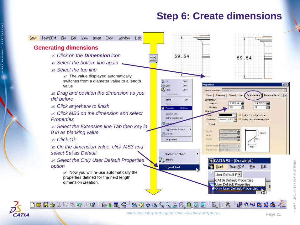
Step 6: Create dimensions
Generating dimensions? Click on the Dimension icon? Select the bottom line again? Select the top line
? The value displayed automaticallyswitches from a diameter value to a lengthvalue
? Drag and position the dimension as youdid before? Click anywhere to finish? Click MB3 on the dimension and selectProperties? Select the Extension line Tab then key in0 in as blanking value? Click Ok? On the dimension value, click MB3 andselect Set as Default? Select the Only User Default Propertiesoption
? Now you will re-use automatically theproperties defined for the next lengthdimension creation.
© 1
997
– 20
01 D
AS
SA
UL
T S
YS
TE
ME
S
Page 22IBM Product Lifecycle Management Solutions / Dassault Systemes
Step 6: Create dimensions
Generating dimensions
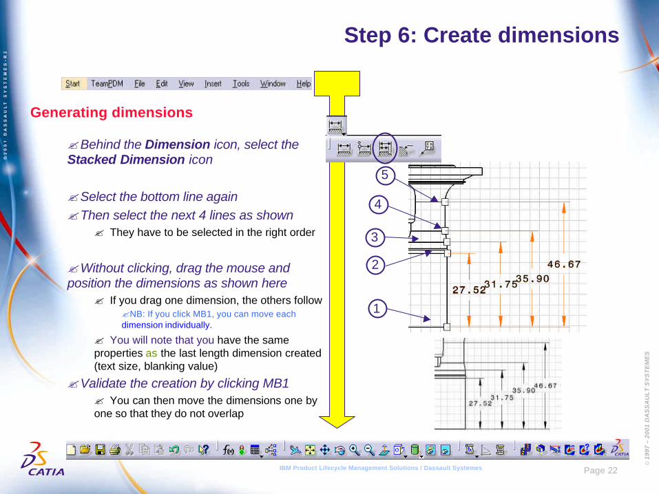
?Behind the Dimension icon, select theStacked Dimension icon
?Select the bottom line again?Then select the next 4 lines as shown
? They have to be selected in the right order
?Without clicking, drag the mouse andposition the dimensions as shown here
? If you drag one dimension, the others follow?NB: If you click MB1, you can move eachdimension individually.
? You will note that you have the sameproperties as the last length dimension created(text size, blanking value)
?Validate the creation by clicking MB1? You can then move the dimensions one byone so that they do not overlap
1
2
3
4
5
© 1
997
– 20
01 D
AS
SA
UL
T S
YS
TE
ME
S
Page 23IBM Product Lifecycle Management Solutions / Dassault Systemes
Step 6: Create dimensions
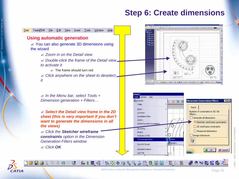
Using automatic generation? You can also generate 3D dimensions usingthe wizard
? Zoom in on the Detail view? Double-click the frame of the Detail viewto activate it
? The frame should turn red
? Click anywhere on the sheet to deselectit
? In the Menu bar, select Tools +Dimension generation + Filters…
? Select the Detail view frame in the 2Dsheet (this is very important if you don’twant to generate the dimensions in allthe views)? Click the Sketcher wireframeconstraints option in the DimensionGeneration Filters window? Click OK
© 1
997
– 20
01 D
AS
SA
UL
T S
YS
TE
ME
S
Page 24IBM Product Lifecycle Management Solutions / Dassault Systemes
Step 6: Create dimensions
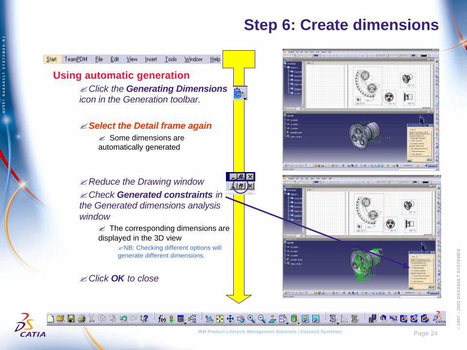
Using automatic generation?Click the Generating Dimensionsicon in the Generation toolbar.
?Select the Detail frame again? Some dimensions areautomatically generated
?Reduce the Drawing window?Check Generated constraints inthe Generated dimensions analysiswindow
? The corresponding dimensions aredisplayed in the 3D view
?NB: Checking different options willgenerate different dimensions.
?Click OK to close
© 1
997
– 20
01 D
AS
SA
UL
T S
YS
TE
ME
S
Page 25IBM Product Lifecycle Management Solutions / Dassault Systemes
Step 6: Create dimensions
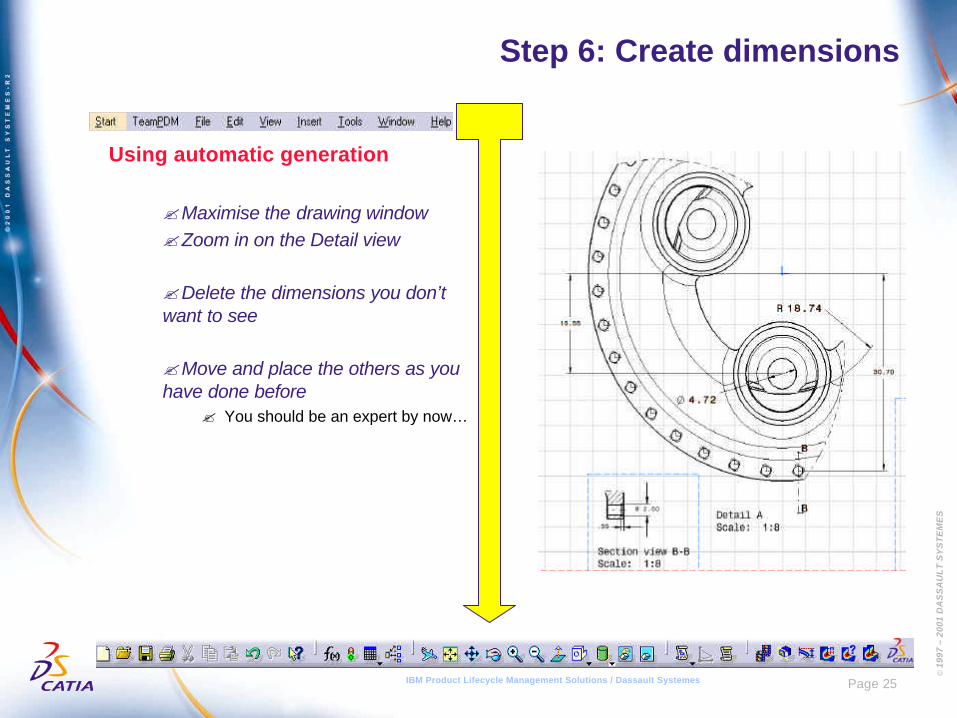
Using automatic generation
?Maximise the drawing window?Zoom in on the Detail view
?Delete the dimensions you don’twant to see
?Move and place the others as youhave done before
? You should be an expert by now…
© 1
997
– 20
01 D
AS
SA
UL
T S
YS
TE
ME
S
Page 26IBM Product Lifecycle Management Solutions / Dassault Systemes
Step 7: Create a Breakout view
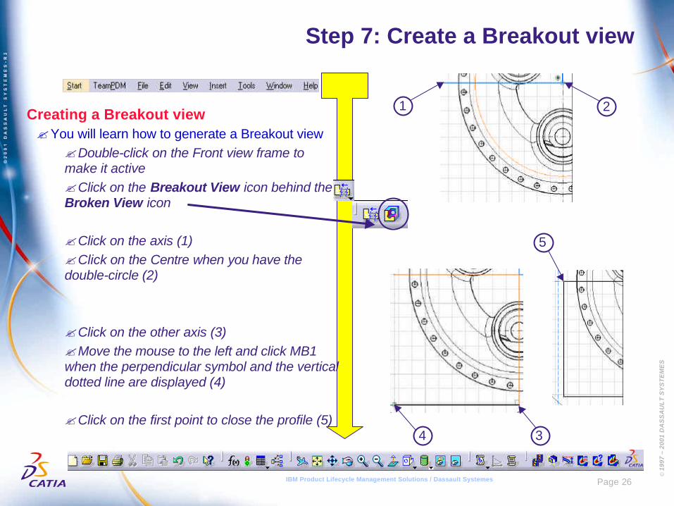
Creating a Breakout view?You will learn how to generate a Breakout view
?Double-click on the Front view frame tomake it active?Click on the Breakout View icon behind theBroken View icon
?Click on the axis (1)?Click on the Centre when you have thedouble-circle (2)
?Click on the other axis (3)?Move the mouse to the left and click MB1when the perpendicular symbol and the verticaldotted line are displayed (4)
?Click on the first point to close the profile (5)
1 2
34
5
© 1
997
– 20
01 D
AS
SA
UL
T S
YS
TE
ME
S
Page 27IBM Product Lifecycle Management Solutions / Dassault Systemes
Step 7: Create a Breakout view
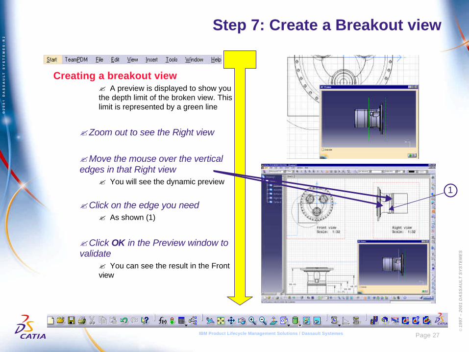
Creating a breakout view? A preview is displayed to show youthe depth limit of the broken view. Thislimit is represented by a green line
?Zoom out to see the Right view
?Move the mouse over the verticaledges in that Right view
? You will see the dynamic preview
?Click on the edge you need? As shown (1)
?Click OK in the Preview window tovalidate
? You can see the result in the Frontview
1
© 1
997
– 20
01 D
AS
SA
UL
T S
YS
TE
ME
S
Page 28IBM Product Lifecycle Management Solutions / Dassault Systemes
Step 7: Create a Breakout view
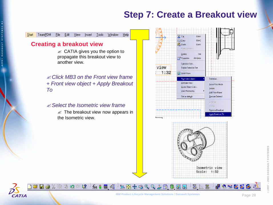
Creating a breakout view? CATIA gives you the option topropagate this breakout view toanother view.
?Click MB3 on the Front view frame+ Front view object + Apply BreakoutTo
?Select the Isometric view frame? The breakout view now appears inthe Isometric view.
© 1
997
– 20
01 D
AS
SA
UL
T S
YS
TE
ME
S
Page 29IBM Product Lifecycle Management Solutions / Dassault Systemes
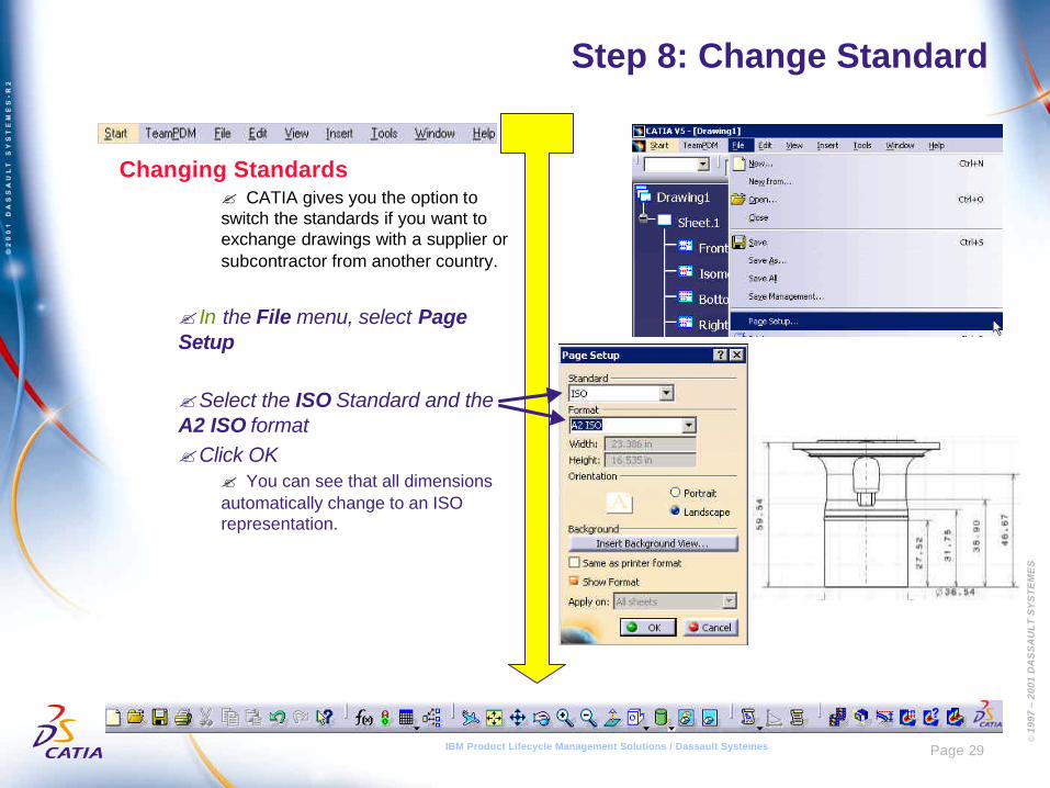
Step 8: Change Standard
Changing Standards? CATIA gives you the option toswitch the standards if you want toexchange drawings with a supplier orsubcontractor from another country.
? In the File menu, select PageSetup
?Select the ISO Standard and theA2 ISO format?Click OK
? You can see that all dimensionsautomatically change to an ISOrepresentation.
© 1
997
– 20
01 D
AS
SA
UL
T S
YS
TE
ME
S
Page 30IBM Product Lifecycle Management Solutions / Dassault Systemes
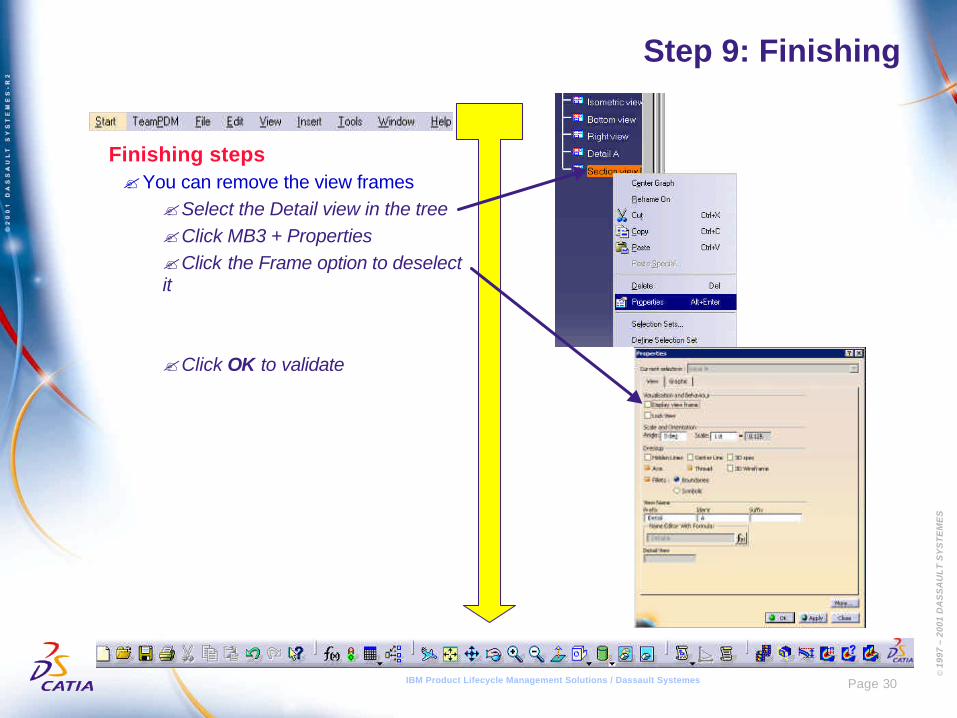
Step 9: Finishing
Finishing steps?You can remove the view frames
?Select the Detail view in the tree?Click MB3 + Properties?Click the Frame option to deselectit
?Click OK to validate
© 1
997
– 20
01 D
AS
SA
UL
T S
YS
TE
ME
S
Page 31IBM Product Lifecycle Management Solutions / Dassault Systemes
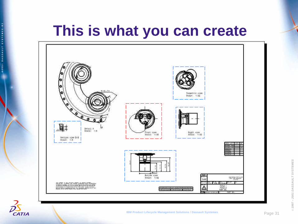
This is what you can create
© 1
997
– 20
01 D
AS
SA
UL
T S
YS
TE
ME
S
Page 32IBM Product Lifecycle Management Solutions / Dassault Systemes
Manual Settings
© 1
997
– 20
01 D
AS
SA
UL
T S
YS
TE
ME
S
Page 33IBM Product Lifecycle Management Solutions / Dassault Systemes
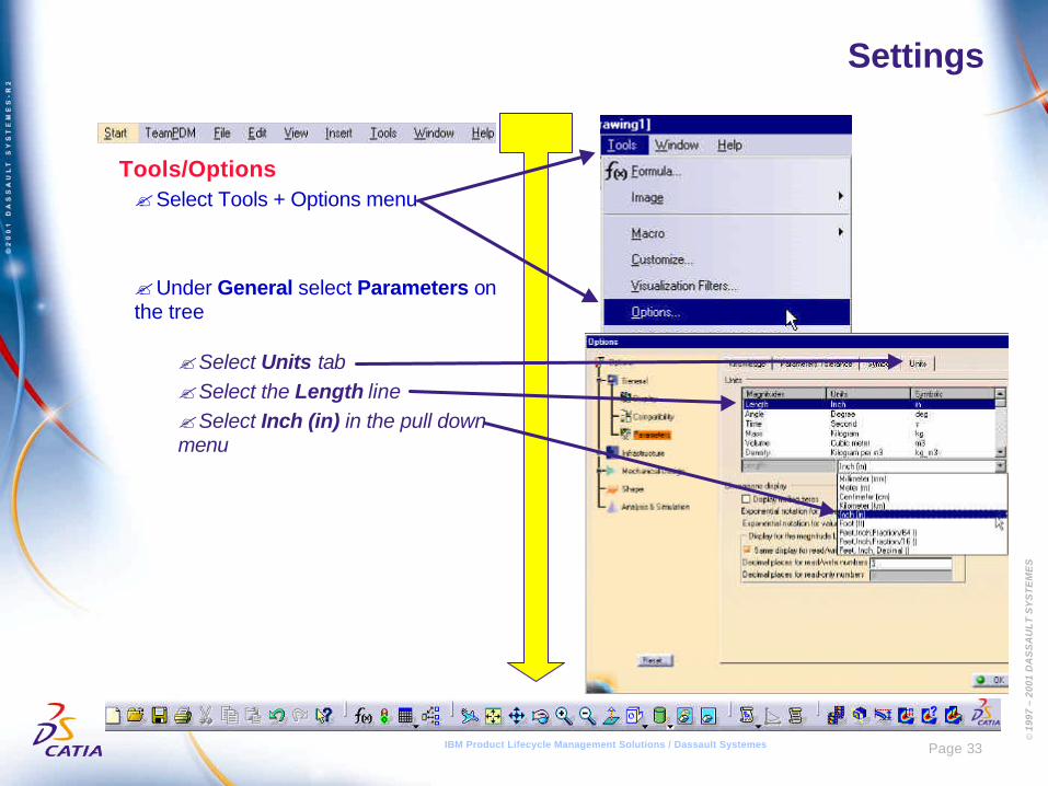
Settings
Tools/Options?Select Tools + Options menu
?Under General select Parameters onthe tree
?Select Units tab?Select the Length line?Select Inch (in) in the pull downmenu
© 1
997
– 20
01 D
AS
SA
UL
T S
YS
TE
ME
S
Page 34IBM Product Lifecycle Management Solutions / Dassault Systemes
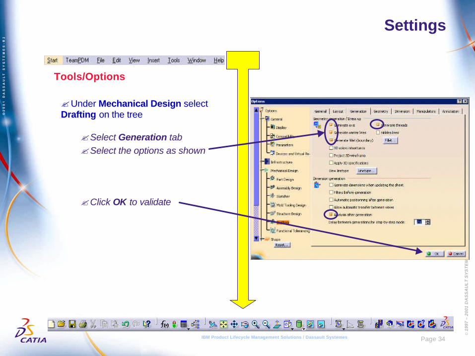
Settings
Tools/Options
?Under Mechanical Design selectDrafting on the tree
?Select Generation tab?Select the options as shown
?Click OK to validate

© 1
997
– 20
01 D
AS
SA
UL
T S
YS
TE
ME
S
Page 35IBM Product Lifecycle Management Solutions / Dassault Systemes
CONGRATULATIONS
IBM Product Lifecycle Management Solutions / Dassault Systemes