catia v5 generative part structural analysis · ?this tutorial is an introduction to generative...
TRANSCRIPT
© 1
997
– 20
01 D
AS
SA
UL
T S
YS
TE
ME
S
IBM Product Lifecycle Management Solutions / Dassault Systemes
Generative Part StructuralAnalysis
IBM Product Lifecycle Management Solutions / Dassault Systemes
© 1
997
– 20
01 D
AS
SA
UL
T S
YS
TE
ME
S
© 1
997
– 20
01 D
AS
SA
UL
T S
YS
TE
ME
S
Page 2IBM Product Lifecycle Management Solutions / Dassault Systemes
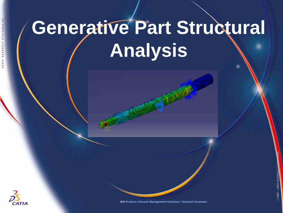
Description?This Tutorial is an introduction to Generative Part Structural Analysis.
Message?To show how Stress Analysis is easy to use - even for the non-analyst?To show how CATIA V5 gives accurate results?To show CATIA V5’s associativity features
Duration?45 minutes
Product Coverage?Assembly Design, Part Design, Generative Part Structural Analysis
Page 2IBM Product Lifecycle Management Solutions / Dassault Systemes
Tutorial Objectives
© 1
997
– 20
01 D
AS
SA
UL
T S
YS
TE
ME
S
© 1
997
– 20
01 D
AS
SA
UL
T S
YS
TE
ME
S
IBM Product Lifecycle Management Solutions / Dassault Systemes
Tutorial Major StepsHere are the major steps of the tutorial:
Step 1? Show the supporting geometry
Step 2? Prepare the part for analysis
Step 3? Assign boundary conditions ( Loads and Restraints)
Step 4? Solve the problem
Step 5? Visualise the results
Step 6? Analyse the results
Step 7? Change the design and resolve
Step 8? Reanalyse the results
IBM Product Lifecycle Management Solutions / Dassault Systemes Page 3
© 1
997
– 20
01 D
AS
SA
UL
T S
YS
TE
ME
S
© 1
997
– 20
01 D
AS
SA
UL
T S
YS
TE
ME
S
IBM Product Lifecycle Management Solutions / Dassault Systemes
© 1
997
– 20
01 D
AS
SA
UL
T S
YS
TE
ME
S
Page 4IBM Product Lifecycle Management Solutions / Dassault Systemes
Settings 1/2Depending on your needs, you may have to modify the CATIA V5 settings (units, defaultdirectory, visualisation parameters, etc…)
In order to use the appropriate settings for this tutorial, you have two possibilities:
1. Do the following operations (simplest one):?BEFORE STARTING YOUR CATIA V5 SESSION:? Copy or replace the directory ..\Generative Part Structural Analysis\Data\CATSettings in:
C:\Winnt\Profiles\XXXXX\Application Data\DassaultSystemesC:\Documents and settings\Profiles\XXXXX\Application Data\DassaultSystemesC:\Windows\Profiles\XXXXX\Application Data\DassaultSystemes XXXX is the name used to log on to your computer
? Do not forget to put this folder (CATSettings) in read mode: ? Select the folder (CATSettings)
? Click mouse button 3 then click on Properties and uncheck the Read-only Attribute? Select all the files in the folder? Click mouse button 3 then click on Properties and uncheck the Read-only
Attribute
2. Set them manually:? Launch your CATIA V5 session and do the operations from page 23 onwards
For NT users
For Windows 2000or XP users
For Windows98 users
© 1
997
– 20
01 D
AS
SA
UL
T S
YS
TE
ME
S
IBM Product Lifecycle Management Solutions / Dassault Systemes
© 1
997
– 20
01 D
AS
SA
UL
T S
YS
TE
ME
S
Page 5IBM Product Lifecycle Management Solutions / Dassault Systemes
Settings 2/2
For this tutorial you also need to install a material catalogue:? Do not do this step if you have already done it in getting started or in a previous tutorial
? Copy the ..\Getting Started\Catalog.CATMaterial file under ..\ProgramFiles\Dassault Systemes\M07\intel_a\startup\materials\French directory
? Copy the ..\Getting Started\Catalog.CATMaterial file under ..\ProgramFiles\Dassault Systemes\M07\intel_a\startup\materials\German directory
? Copy the ..\Getting Started\Catalog.CATMaterial file under ..\ProgramFiles\Dassault Systemes\M07\intel_a\startup\materials\Japanese directory
? Copy the ..\Getting Started\Catalog.CATMaterial file under ..\ProgramFiles\Dassault Systemes\M07\intel_a\startup\materials directory
? Answer Yes in order to replace the old catalogue
You are now ready to launch your CATIA V5 session
© 1
997
– 20
01 D
AS
SA
UL
T S
YS
TE
ME
S
Page 6IBM Product Lifecycle Management Solutions / Dassault Systemes
Step 1: Show the Supporting Geometry
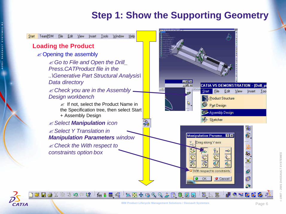
Loading the Product?Opening the assembly
?Go to File and Open the Drill_Press.CATProduct file in the..\Generative Part Structural Analysis\Data directory?Check you are in the AssemblyDesign workbench
? If not, select the Product Name inthe Specification tree, then select Start+ Assembly Design
?Select Manipulation icon?Select Y Translation inManipulation Parameters window?Check the With respect toconstraints option box
© 1
997
– 20
01 D
AS
SA
UL
T S
YS
TE
ME
S
Page 7IBM Product Lifecycle Management Solutions / Dassault Systemes
Step 1: Show the Supporting Assembly
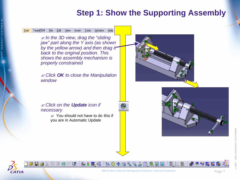
? In the 3D view, drag the “slidingjaw” part along the Y axis (as shownby the yellow arrow) and then drag itback to the original position. Thisshows the assembly mechanism isproperly constrained
?Click OK to close the Manipulationwindow
?Click on the Update icon ifnecessary
? You should not have to do this ifyou are in Automatic Update
© 1
997
– 20
01 D
AS
SA
UL
T S
YS
TE
ME
S
Page 8IBM Product Lifecycle Management Solutions / Dassault Systemes
Step 1: Show the Supporting Assembly
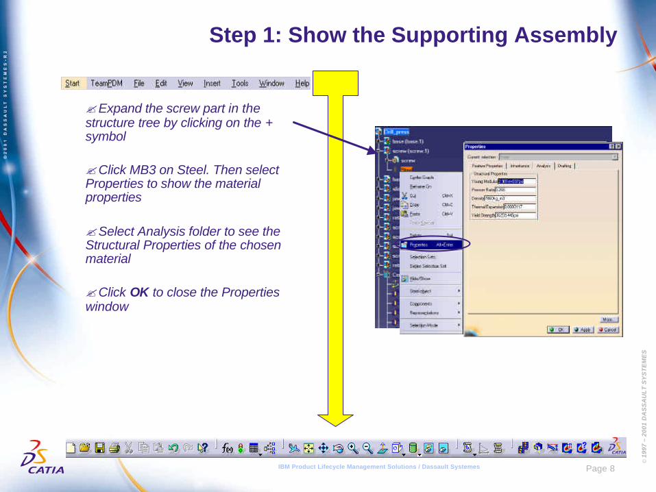
?Expand the screw part in thestructure tree by clicking on the +symbol
?Click MB3 on Steel. Then selectProperties to show the materialproperties
?Select Analysis folder to see theStructural Properties of the chosenmaterial
?Click OK to close the Propertieswindow
© 1
997
– 20
01 D
AS
SA
UL
T S
YS
TE
ME
S
Page 9IBM Product Lifecycle Management Solutions / Dassault Systemes
Step 2: Prepare the part for Analysis
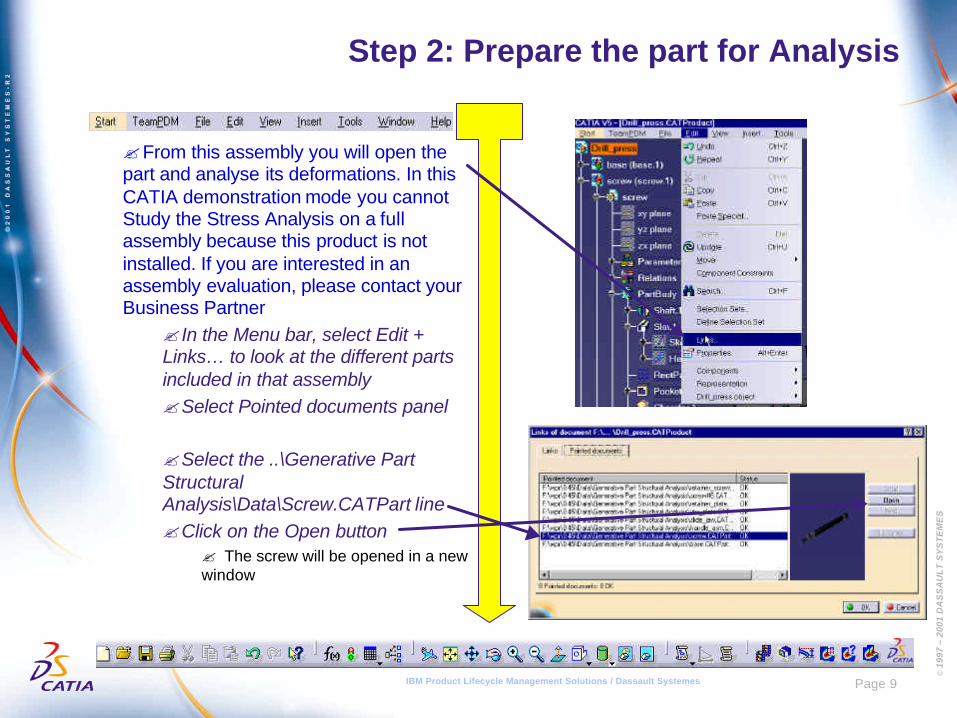
?From this assembly you will open thepart and analyse its deformations. In thisCATIA demonstration mode you cannotStudy the Stress Analysis on a fullassembly because this product is notinstalled. If you are interested in anassembly evaluation, please contact yourBusiness Partner
? In the Menu bar, select Edit +Links… to look at the different partsincluded in that assembly?Select Pointed documents panel
?Select the ..\Generative PartStructuralAnalysis\Data\Screw.CATPart line?Click on the Open button
? The screw will be opened in a newwindow
© 1
997
– 20
01 D
AS
SA
UL
T S
YS
TE
ME
S
Page 10IBM Product Lifecycle Management Solutions / Dassault Systemes
Step 2: Prepare the part for Analysis
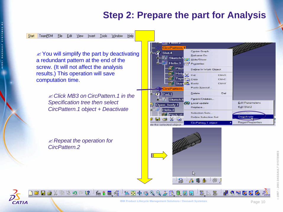
?You will simplify the part by deactivatinga redundant pattern at the end of thescrew. (It will not affect the analysisresults.) This operation will savecomputation time.
?Click MB3 on CircPattern.1 in theSpecification tree then selectCircPattern.1 object + Deactivate
?Repeat the operation forCircPattern.2
© 1
997
– 20
01 D
AS
SA
UL
T S
YS
TE
ME
S
Page 11IBM Product Lifecycle Management Solutions / Dassault Systemes
Step 2: Prepare the part for Analysis
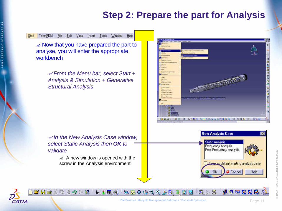
?Now that you have prepared the part toanalyse, you will enter the appropriateworkbench
?From the Menu bar, select Start +Analysis & Simulation + GenerativeStructural Analysis
? In the New Analysis Case window,select Static Analysis then OK tovalidate
? A new window is opened with thescrew in the Analysis environment
© 1
997
– 20
01 D
AS
SA
UL
T S
YS
TE
ME
S
Page 12IBM Product Lifecycle Management Solutions / Dassault Systemes
Step 3: Assign Boundary Conditions
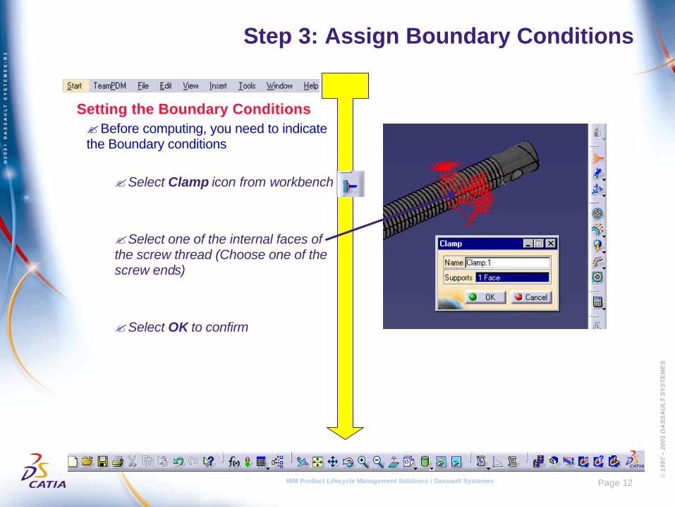
Setting the Boundary Conditions?Before computing, you need to indicatethe Boundary conditions
?Select Clamp icon from workbench
?Select one of the internal faces ofthe screw thread (Choose one of thescrew ends)
?Select OK to confirm
© 1
997
– 20
01 D
AS
SA
UL
T S
YS
TE
ME
S
Page 13IBM Product Lifecycle Management Solutions / Dassault Systemes
Step 3: Assign Boundary Conditions
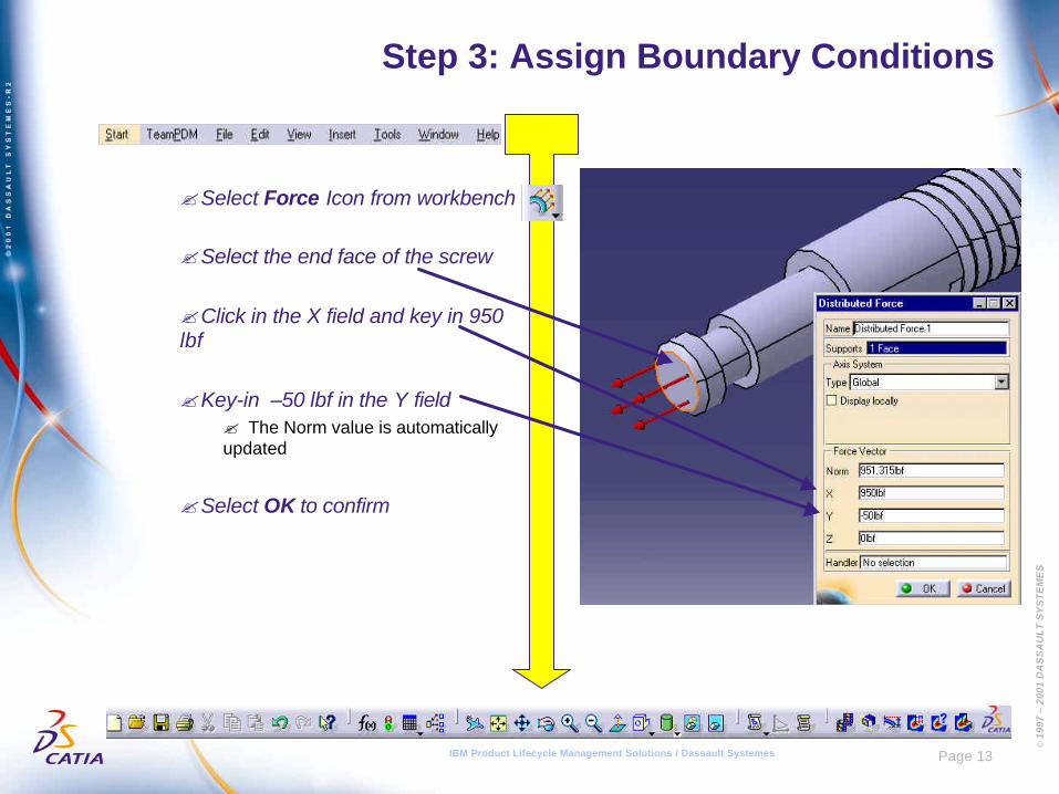
?Select Force Icon from workbench
?Select the end face of the screw
?Click in the X field and key in 950lbf
?Key-in –50 lbf in the Y field? The Norm value is automaticallyupdated
?Select OK to confirm

© 1
997
– 20
01 D
AS
SA
UL
T S
YS
TE
ME
S
Page 14IBM Product Lifecycle Management Solutions / Dassault Systemes
Step 4: Solve the problem
Computing the load problem?Setting the Temporary file calculation
?Click on the Elfini Storage Location icon?Define the corresponding directory E:\Tempusing Modify
? The results will be stored on your hard disk.You should not need more than 50MB. Todelete the results files, you can either manuallydelete them in Windows or click on the Clearbutton
?Select the Compute icon?Check the Preview option
?Click on the OK button to launch thecalculation
?After a few seconds, CATIA will come backwith an estimated time for computation of thisproblem.?Click Yes to continue
© 1
997
– 20
01 D
AS
SA
UL
T S
YS
TE
ME
S
Page 15IBM Product Lifecycle Management Solutions / Dassault Systemes
Step 5: Visualise the Results
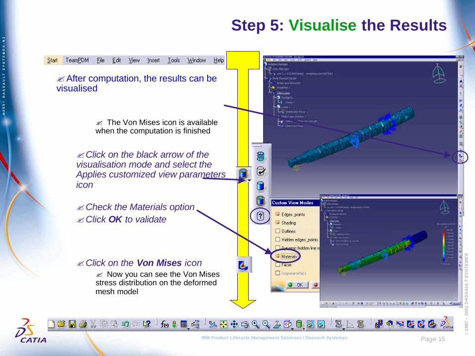
?After computation, the results can bevisualised
? The Von Mises icon is availablewhen the computation is finished
?Click on the black arrow of thevisualisation mode and select theApplies customized view parametersicon
?Check the Materials option?Click OK to validate
?Click on the Von Mises icon? Now you can see the Von Misesstress distribution on the deformedmesh model

© 1
997
– 20
01 D
AS
SA
UL
T S
YS
TE
ME
S
Page 16IBM Product Lifecycle Management Solutions / Dassault Systemes
Step 5: Visualise the Results
?Visualising the Von Mises image? To improve your view, hide Propertiesand Nodes and Elements usinghide/show in their contextual menu
?Multi-select both Nodes andElements and Properties in thespecification tree by holding down theCTRL key?Click MB3 on Properties + Hide/Show
?Move mouse cursor over finite elementsto visualise Von Mises values at eachnode
?You can modify the result display?Double-click on the palette?Enter 20 instead of 10
?Click OK to close the panel
© 1
997
– 20
01 D
AS
SA
UL
T S
YS
TE
ME
S
Page 17IBM Product Lifecycle Management Solutions / Dassault Systemes
Step 6: Analyse the Results
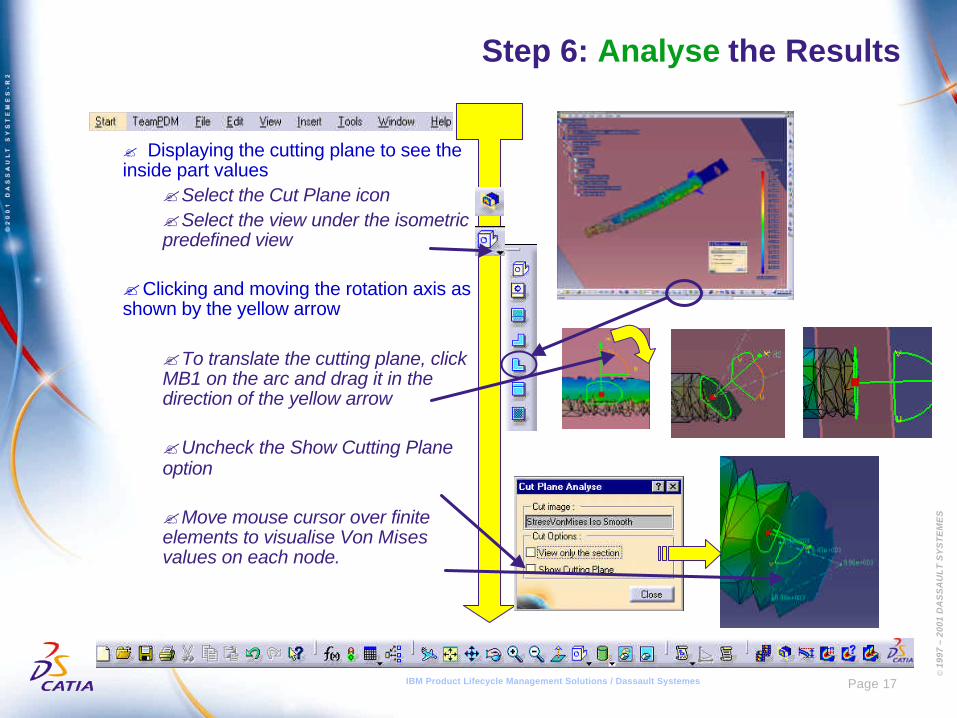
? Displaying the cutting plane to see theinside part values
?Select the Cut Plane icon?Select the view under the isometricpredefined view
?Clicking and moving the rotation axis asshown by the yellow arrow
?To translate the cutting plane, clickMB1 on the arc and drag it in thedirection of the yellow arrow
?Uncheck the Show Cutting Planeoption
?Move mouse cursor over finiteelements to visualise Von Misesvalues on each node.
© 1
997
– 20
01 D
AS
SA
UL
T S
YS
TE
ME
S
Page 18IBM Product Lifecycle Management Solutions / Dassault Systemes
Step 6: Analyse the Results
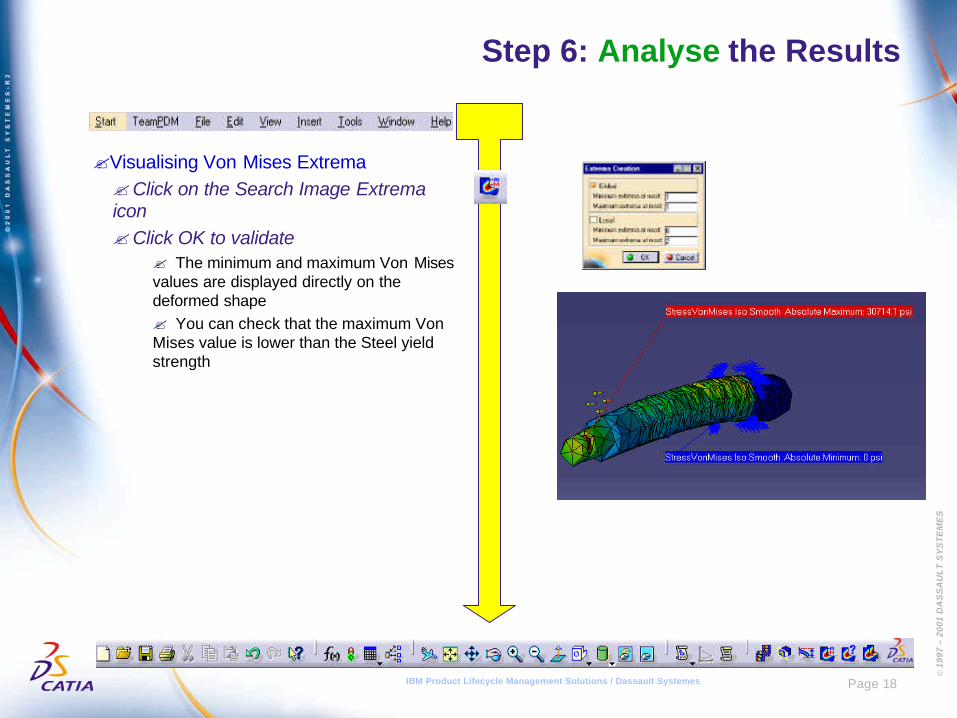
?Visualising Von Mises Extrema?Click on the Search Image Extremaicon?Click OK to validate
? The minimum and maximum Von Misesvalues are displayed directly on thedeformed shape? You can check that the maximum VonMises value is lower than the Steel yieldstrength
© 1
997
– 20
01 D
AS
SA
UL
T S
YS
TE
ME
S
Page 19IBM Product Lifecycle Management Solutions / Dassault Systemes
Step 6: Analyse the Results
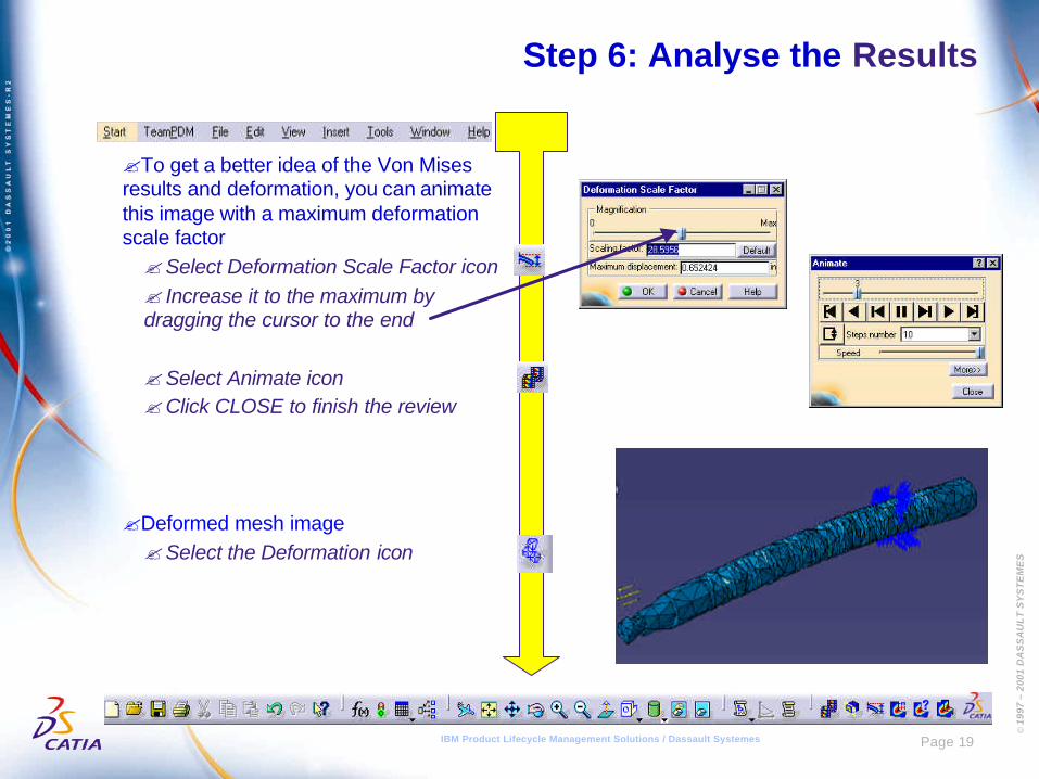
?To get a better idea of the Von Misesresults and deformation, you can animatethis image with a maximum deformationscale factor?Select Deformation Scale Factor icon? Increase it to the maximum bydragging the cursor to the end
?Select Animate icon?Click CLOSE to finish the review
?Deformed mesh image?Select the Deformation icon
© 1
997
– 20
01 D
AS
SA
UL
T S
YS
TE
ME
S
Page 20IBM Product Lifecycle Management Solutions / Dassault Systemes
Step 7: Change the Design and Resolve
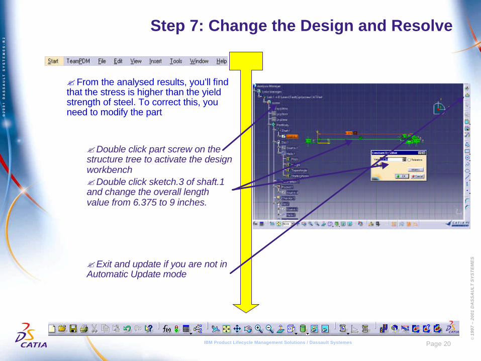
?From the analysed results, you’ll findthat the stress is higher than the yieldstrength of steel. To correct this, youneed to modify the part
?Double click part screw on thestructure tree to activate the designworkbench?Double click sketch.3 of shaft.1and change the overall lengthvalue from 6.375 to 9 inches.
?Exit and update if you are not inAutomatic Update mode
© 1
997
– 20
01 D
AS
SA
UL
T S
YS
TE
ME
S
Page 21IBM Product Lifecycle Management Solutions / Dassault Systemes
Step 8: Reanalyse the results
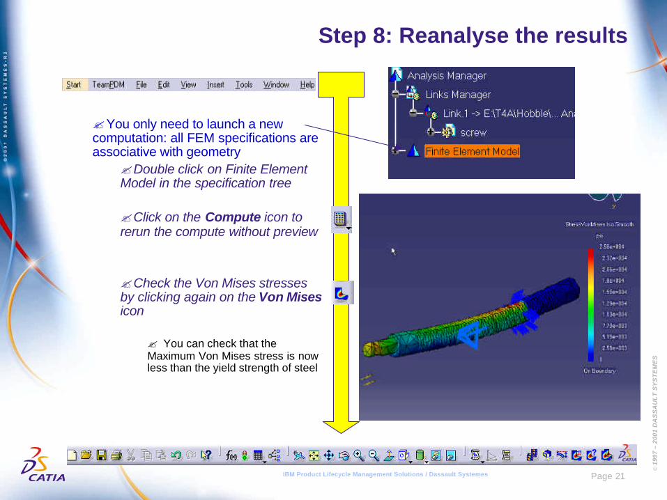
?You only need to launch a newcomputation: all FEM specifications areassociative with geometry
?Double click on Finite ElementModel in the specification tree
?Click on the Compute icon torerun the compute without preview
?Check the Von Mises stressesby clicking again on the Von Misesicon
? You can check that theMaximum Von Mises stress is nowless than the yield strength of steel
© 1
997
– 20
01 D
AS
SA
UL
T S
YS
TE
ME
S
IBM Product Lifecycle Management Solutions / Dassault Systemes
Manual Settings
© 1
997
– 20
01 D
AS
SA
UL
T S
YS
TE
ME
S
IBM Product Lifecycle Management Solutions / Dassault Systemes
© 1
997
– 20
01 D
AS
SA
UL
T S
YS
TE
ME
S
Page 23IBM Product Lifecycle Management Solutions / Dassault Systemes
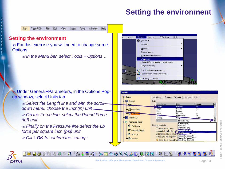
Setting the environment
Setting the environment?For this exercise you will need to change someOptions
? In the Menu bar, select Tools + Options…
?Under General+Parameters, in the Options Pop-up window, select Units tab
?Select the Length line and with the scrolldown menu, choose the Inch(in) unit?On the Force line, select the Pound Force(lbf) unit?Finally on the Pressure line select the Lb.force per square inch (psi) unit?Click OK to confirm the settings
© 1
997
– 20
01 D
AS
SA
UL
T S
YS
TE
ME
S
IBM Product Lifecycle Management Solutions / Dassault Systemes
Congratulations
© 1
997
– 20
01 D
AS
SA
UL
T S
YS
TE
ME
S
IBM Product Lifecycle Management Solutions / Dassault Systemes