generative assembly structural analysis - freeyvonet.florent.free.fr/serveur/cours catia/catia...
TRANSCRIPT

CATIA Training
COPYRIGHT DASSAULT SYSTEMES Version 5 Release 19 September 2008 EDU-CAT-EN-GAS-FS-V5R19
GGeenneerraattiivvee AAsssseemmbbllyy SSttrruuccttuurraall AAnnaallyyssiiss
DDeettaaiilleedd SStteeppss
Generative Assembly Structural Analysis Detailed Steps
COPYRIGHT DASSAULT SYSTEMES 2
TTaabbllee ooff CCoonntteennttss Recap Exercises ..................................................................................................................................... 3�
1. Face Face Connections Property Recap Exercise ......................................................................... 3�2. Distant Connections Recap Exercise ............................................................................................ 11�
Master Exercise: Static Analysis on an Assembly ................................................................................ 19�1. Pre-Processing .............................................................................................................................. 19�2. Computation .................................................................................................................................. 41�3. Results Visualization ..................................................................................................................... 44�4. Publishing Report .......................................................................................................................... 51�
�������������� ������������������� �������������
COPYRIGHT DASSAULT SYSTEMES 3
Recap Exercises
1. Face Face Connections Property Recap Exercise
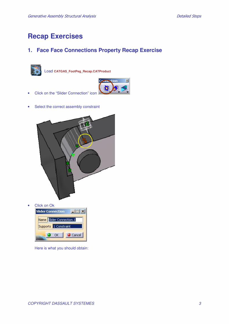
Load CATGAS_FootPeg_Recap.CATProduct
• Click on the “Slider Connection” icon • Select the correct assembly constraint
• Click on Ok
Here is what you should obtain:

�������������� ������������������� �������������
COPYRIGHT DASSAULT SYSTEMES 4
• Click on the “Contact Connection” icon • Select the correct assembly constraint
• Click on Ok
Below is what you should obtain:
�������������� ������������������� �������������
COPYRIGHT DASSAULT SYSTEMES 5
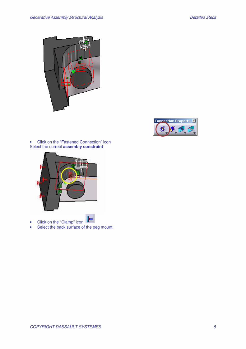
• Click on the “Fastened Connection” icon Select the correct assembly constraint
• Click on the “Clamp” icon • Select the back surface of the peg mount

�������������� ������������������� �������������
COPYRIGHT DASSAULT SYSTEMES 6
• Click on Ok • Apply surface slider on cylindrical surface of foot peg. Click on surface slider Select the inner cylindrical face of peg

�������������� ������������������� �������������
COPYRIGHT DASSAULT SYSTEMES 7
You will get :
Below is what you should finally obtain:
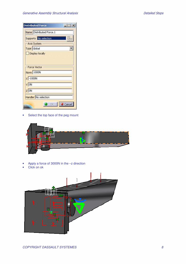
• Click on the “Distributed Force” icon
�������������� ������������������� �������������
COPYRIGHT DASSAULT SYSTEMES 8
• Select the top face of the peg mount
• Apply a force of 3000N in the –z direction • Click on ok
�������������� ������������������� �������������
COPYRIGHT DASSAULT SYSTEMES 9
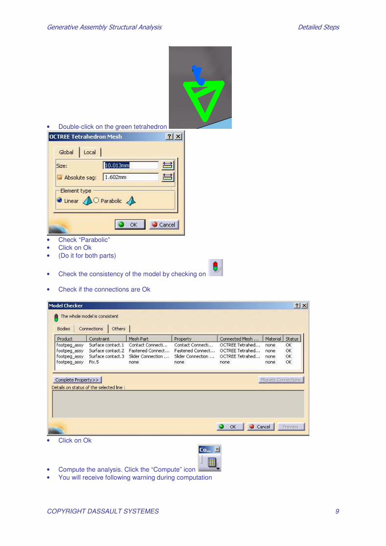
• Double-click on the green tetrahedron
• Check “Parabolic” • Click on Ok • (Do it for both parts)
• Check the consistency of the model by checking on • Check if the connections are Ok
• Click on Ok
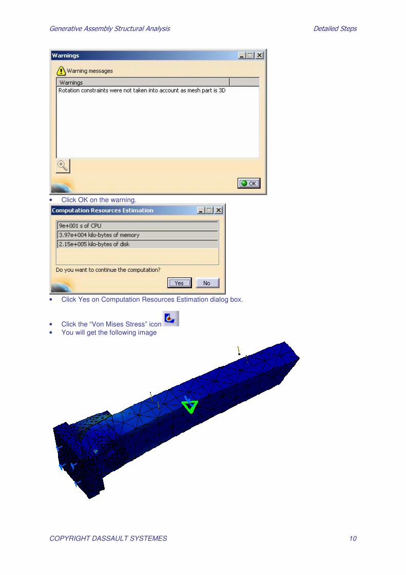
• Compute the analysis. Click the “Compute” icon • You will receive following warning during computation
�������������� ������������������� �������������
COPYRIGHT DASSAULT SYSTEMES 10
• Click OK on the warning.
• Click Yes on Computation Resources Estimation dialog box.
• Click the “Von Mises Stress” icon • You will get the following image
�������������� ������������������� �������������
COPYRIGHT DASSAULT SYSTEMES 11
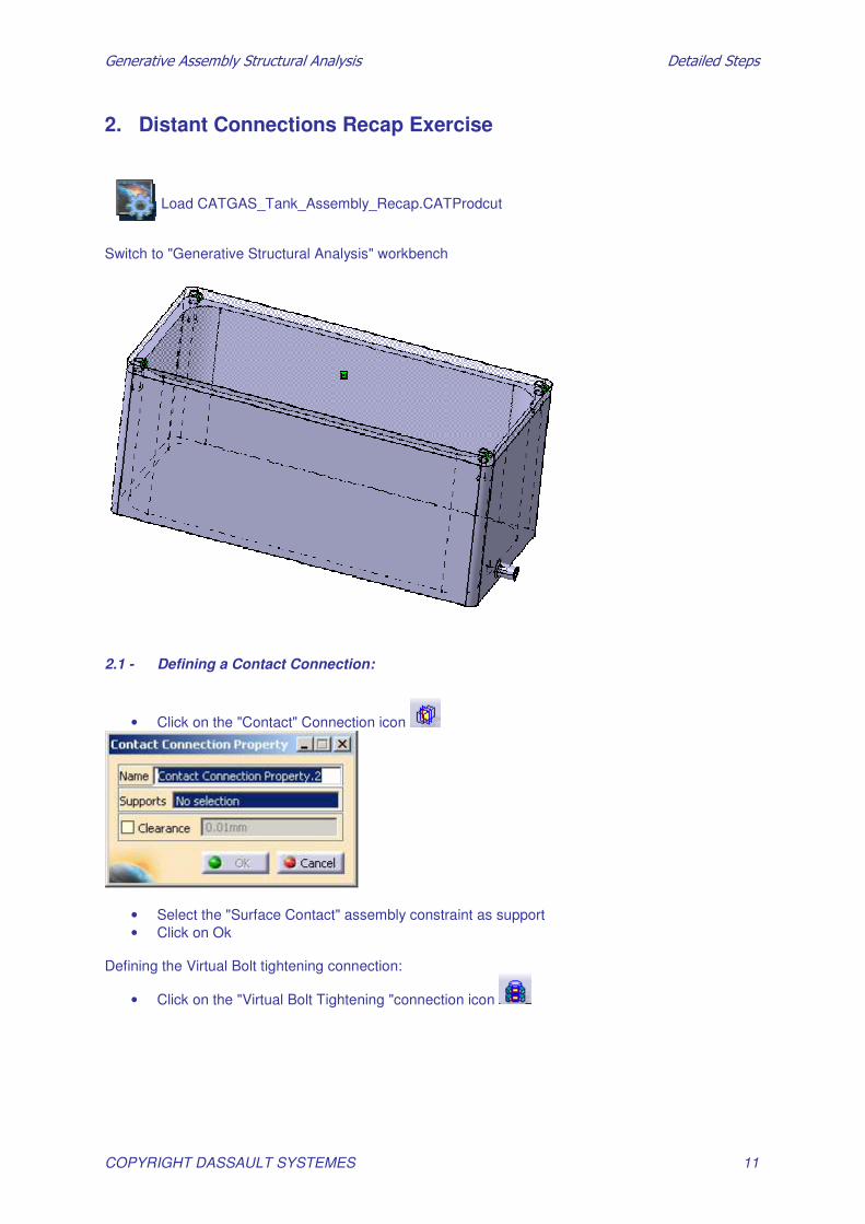
2. Distant Connections Recap Exercise
Load CATGAS_Tank_Assembly_Recap.CATProdcut Switch to "Generative Structural Analysis" workbench
2.1 - Defining a Contact Connection:
• Click on the "Contact" Connection icon
• Select the "Surface Contact" assembly constraint as support • Click on Ok
Defining the Virtual Bolt tightening connection:
• Click on the "Virtual Bolt Tightening "connection icon
�������������� ������������������� �������������
COPYRIGHT DASSAULT SYSTEMES 12
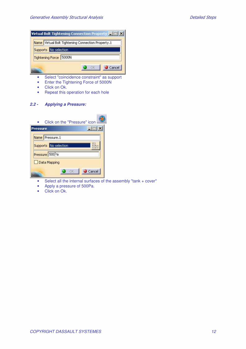
• Select "coincidence constraint" as support • Enter the Tightening Force of 5000N • Click on Ok. • Repeat this operation for each hole
2.2 - Applying a Pressure:
• Click on the "Pressure" icon
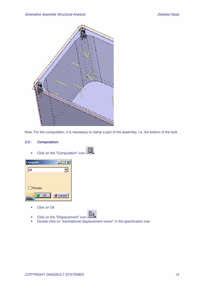
• Select all the internal surfaces of the assembly "tank + cover" • Apply a pressure of 500Pa. • Click on Ok.
�������������� ������������������� �������������
COPYRIGHT DASSAULT SYSTEMES 13
Note: For the computation, it is necessary to clamp a part of the assembly, i.e. the bottom of the tank.
2.3 - Computation
• Click on the "Computation" icon
• Click on Ok
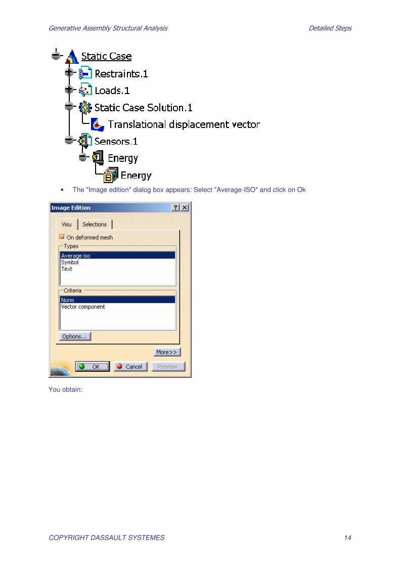
• Click on the "Displacement" icon • Double-click on "translational displacement vector" in the specification tree
�������������� ������������������� �������������
COPYRIGHT DASSAULT SYSTEMES 14
• The "Image edition" dialog box appears: Select "Average-ISO" and click on Ok
You obtain:

�������������� ������������������� �������������
COPYRIGHT DASSAULT SYSTEMES 15
• Change the "deformation scale factor" for a better visualization
• Click on the “Precision” icon.
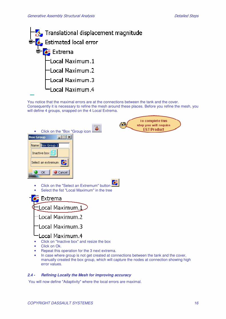
• Click on the "Image Extrema" icon • Ask for 4 "Local Maxima extrema" detection:
• Click on Ok You should get this in the tree:
�������������� ������������������� �������������
COPYRIGHT DASSAULT SYSTEMES 16
You notice that the maximal errors are at the connections between the tank and the cover. Consequently it is necessary to refine the mesh around these places. Before you refine the mesh, you will define 4 groups, snapped on the 4 Local Extrema.
• Click on the "Box "Group icon
• Click on the "Select an Extremum" button • Select the fist "Local Maximum" in the tree
• Click on "Inactive box" and resize the box • Click on Ok. • Repeat this operation for the 3 next extrema. • In case where group is not get created at connections between the tank and the cover,
manually created the box group, which will capture the nodes at connection showing high error values.
2.4 - Refining Locally the Mesh for improving accuracy
You will now define "Adaptivity" where the local errors are maximal.

�������������� ������������������� �������������
COPYRIGHT DASSAULT SYSTEMES 17
• Click on the "Global Adaptivity" icon
• Select the "Mesh Part" as support: • Enter "10%" as objective error • Click on Ok
• Compute the analysis with Adaptivity
• Now you will define 4 "local adaptivity"
• In the tree, right-click on "Global Adaptivity"
• Click on "Local Adaptivity"

�������������� ������������������� �������������
COPYRIGHT DASSAULT SYSTEMES 18
This dialog box appears:
• Select as support one of the "Box" groups you have define above
• Enter an objective error of 5% • Define 3 others "Local adaptivity" using the 3 others groups
• Compute using "adaptivity" Use 3 iterations.

�������������� ������������������� �������������
COPYRIGHT DASSAULT SYSTEMES 19
Master Exercise: Static Analysis on an Assembly
1. Pre-Processing
Load the CATIA document “Assembly.CATProduct”
• Open the Assembly.CATPoduct
The assembly is opened in the Assembly Design Workbench.
1.1 - Material Properties
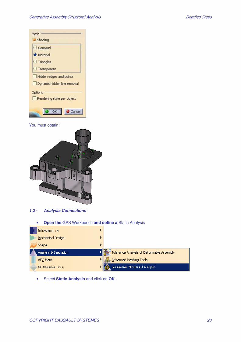
Go to Custom View Modes and check Material option
�������������� ������������������� �������������
COPYRIGHT DASSAULT SYSTEMES 20
You must obtain:
1.2 - Analysis Connections
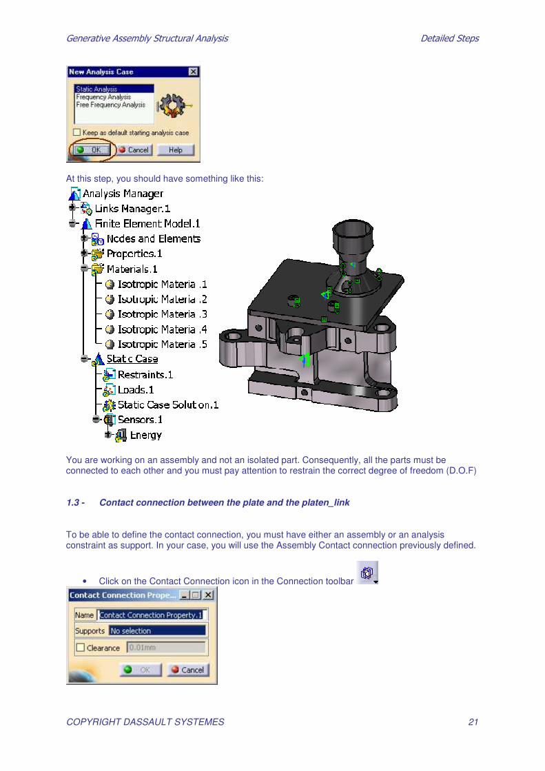
• Open the GPS Workbench and define a Static Analysis
• Select Static Analysis and click on OK.
�������������� ������������������� �������������
COPYRIGHT DASSAULT SYSTEMES 21
At this step, you should have something like this:
You are working on an assembly and not an isolated part. Consequently, all the parts must be connected to each other and you must pay attention to restrain the correct degree of freedom (D.O.F)
1.3 - Contact connection between the plate and the platen_link
To be able to define the contact connection, you must have either an assembly or an analysis constraint as support. In your case, you will use the Assembly Contact connection previously defined.
• Click on the Contact Connection icon in the Connection toolbar

�������������� ������������������� �������������
COPYRIGHT DASSAULT SYSTEMES 22
• Select the contact assembly connection that links the two parts together:
You get this:
• click on Ok
�������������� ������������������� �������������
COPYRIGHT DASSAULT SYSTEMES 23
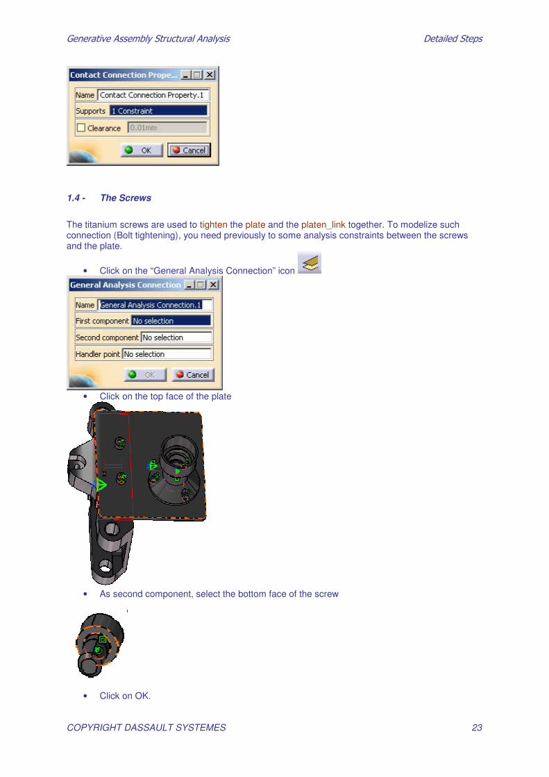
1.4 - The Screws
The titanium screws are used to tighten the plate and the platen_link together. To modelize such connection (Bolt tightening), you need previously to some analysis constraints between the screws and the plate.
• Click on the “General Analysis Connection” icon
• Click on the top face of the plate
• As second component, select the bottom face of the screw
• Click on OK.

�������������� ������������������� �������������
COPYRIGHT DASSAULT SYSTEMES 24
You obtain:
1.5 - Define another “General Analysis Connection” on the second screw
You should obtain:

�������������� ������������������� �������������
COPYRIGHT DASSAULT SYSTEMES 25
Now you have defined 2 “General Analysis” connections, you will use them as support to define a contact connection.
Click on the Contact Connection icon in the Connection toolbar
• Select one of the general connection • Click on Ok • Repeat this operation for the second general connection. You obtain:
�������������� ������������������� �������������
COPYRIGHT DASSAULT SYSTEMES 26
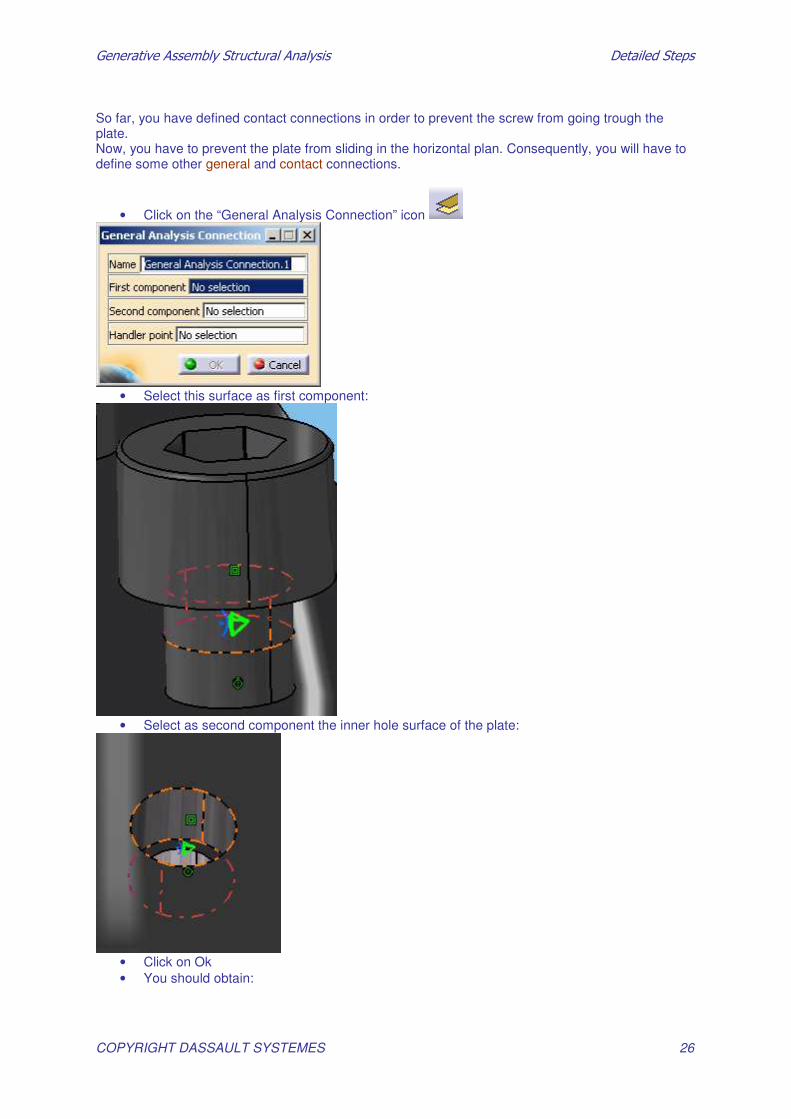
So far, you have defined contact connections in order to prevent the screw from going trough the plate. Now, you have to prevent the plate from sliding in the horizontal plan. Consequently, you will have to define some other general and contact connections.
• Click on the “General Analysis Connection” icon
• Select this surface as first component:
• Select as second component the inner hole surface of the plate:
• Click on Ok • You should obtain:
�������������� ������������������� �������������
COPYRIGHT DASSAULT SYSTEMES 27
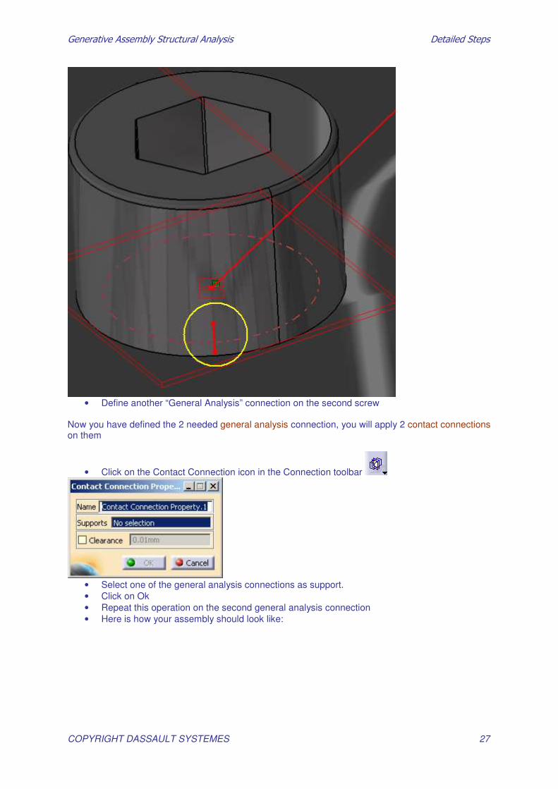
• Define another “General Analysis” connection on the second screw
Now you have defined the 2 needed general analysis connection, you will apply 2 contact connections on them
• Click on the Contact Connection icon in the Connection toolbar
• Select one of the general analysis connections as support. • Click on Ok • Repeat this operation on the second general analysis connection • Here is how your assembly should look like:

�������������� ������������������� �������������
COPYRIGHT DASSAULT SYSTEMES 28
Now that you have restraint the D.O.F of the plate and the screw, you can define the bolt tightening connection
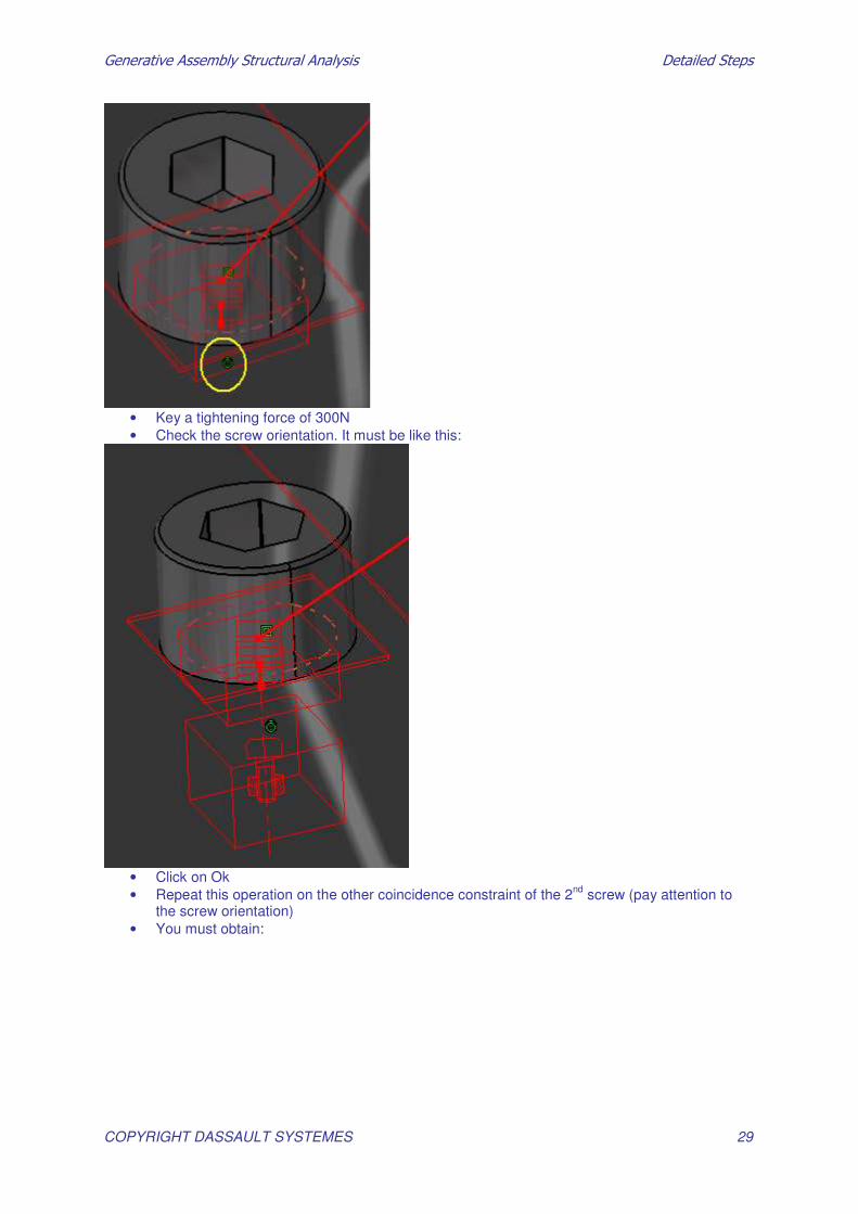
• Click on the “ Bolt tightening” connection icon
• Select as support the assembly coincident constraints
�������������� ������������������� �������������
COPYRIGHT DASSAULT SYSTEMES 29
• Key a tightening force of 300N • Check the screw orientation. It must be like this:
• Click on Ok • Repeat this operation on the other coincidence constraint of the 2nd screw (pay attention to
the screw orientation) • You must obtain:

�������������� ������������������� �������������
COPYRIGHT DASSAULT SYSTEMES 30
You are now done with the screws. You will now fix the shaft on the plate using “virtual Bolt tightening” connection As above, besides of the virtual bolt tightening, you will have to define some general/contact analysis connection to restraint enough the D.O.F of the shaft You will now define a contact connection to prevent the shaft from going trough the plate
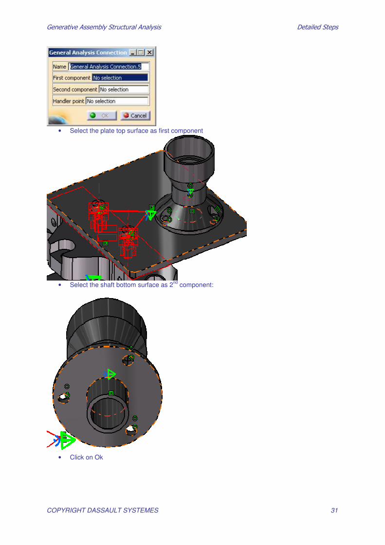
1.6 - Define a general analysis connection between the top surface of the plate and the bottom surface of the shaft:
• Click on the “General Analysis Connection” icon
�������������� ������������������� �������������
COPYRIGHT DASSAULT SYSTEMES 31
• Select the plate top surface as first component
• Select the shaft bottom surface as 2nd component:
• Click on Ok
�������������� ������������������� �������������
COPYRIGHT DASSAULT SYSTEMES 32
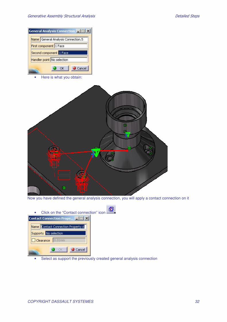
• Here is what you obtain:
Now you have defined the general analysis connection, you will apply a contact connection on it
• Click on the “Contact connection” icon
• Select as support the previously created general analysis connection
�������������� ������������������� �������������
COPYRIGHT DASSAULT SYSTEMES 33
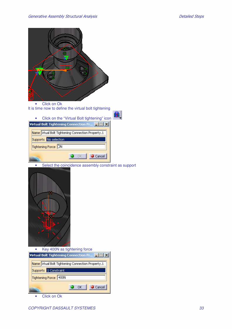
• Click on Ok
It is time now to define the virtual bolt tightening
• Click on the “Virtual Bolt tightening” icon
• Select the coincidence assembly constraint as support
• Key 400N as tightening force
• Click on Ok

�������������� ������������������� �������������
COPYRIGHT DASSAULT SYSTEMES 34
• Repeat this operation for the 2 other holes
• At the end, you should get:
You are now done with the connections between the parts. The 2nd step consist in restraining the platen_link
1.7 - Restraints
• Click on the slider connection icon
• Select the holes inner surfaces:

�������������� ������������������� �������������
COPYRIGHT DASSAULT SYSTEMES 35
• Click on Ok
You will now restrain the X direction
• Click on
• Select the platen_link bottom surface
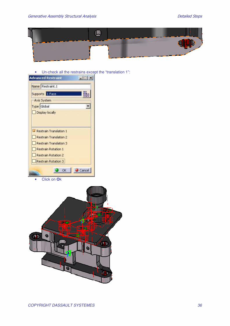
�������������� ������������������� �������������
COPYRIGHT DASSAULT SYSTEMES 36
• Un-check all the restrains except the “translation 1”:
• Click on Ok

�������������� ������������������� �������������
COPYRIGHT DASSAULT SYSTEMES 37
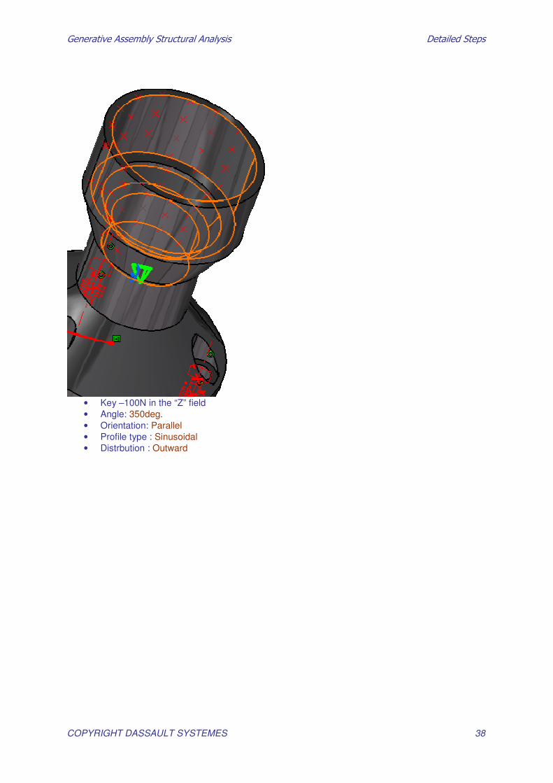
1.8 - Load
You will apply a bearing load
• Click on
• Select these 3 surfaces as support:
�������������� ������������������� �������������
COPYRIGHT DASSAULT SYSTEMES 38
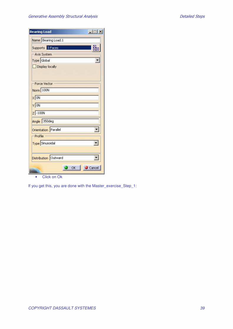
• Key –100N in the “Z” field • Angle: 350deg. • Orientation: Parallel • Profile type : Sinusoidal • Distrbution : Outward
�������������� ������������������� �������������
COPYRIGHT DASSAULT SYSTEMES 39
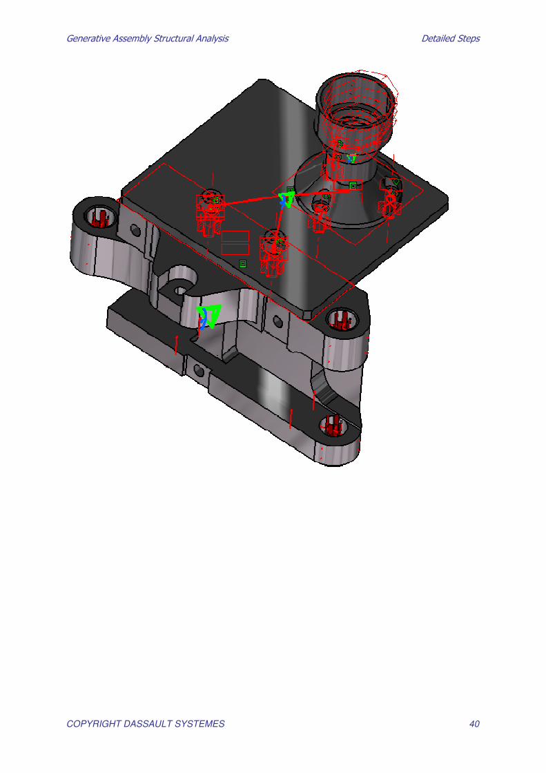
• Click on Ok
If you get this, you are done with the Master_exercise_Step_1:
�������������� ������������������� �������������
COPYRIGHT DASSAULT SYSTEMES 40

�������������� ������������������� �������������
COPYRIGHT DASSAULT SYSTEMES 41
2. Computation
Load the previous CATIA Document "Master_Exercise_Step2" First of all you have to specify an External Storage location. 1.
• Click on Temporary Data Location icon in the Storage Location toolbar. • Select a directory with enough space to make the computation.
• In the features tree, double-click on the Computations link and define a directory where the
computation files will be saved
• Select a path and click on OK to validate.

�������������� ������������������� �������������
COPYRIGHT DASSAULT SYSTEMES 42
• In the specification tree, double-click on the Results link and define a directory where the results files will be saved
• Select a path and click on OK to validate.
2.
�������������� ������������������� �������������
COPYRIGHT DASSAULT SYSTEMES 43
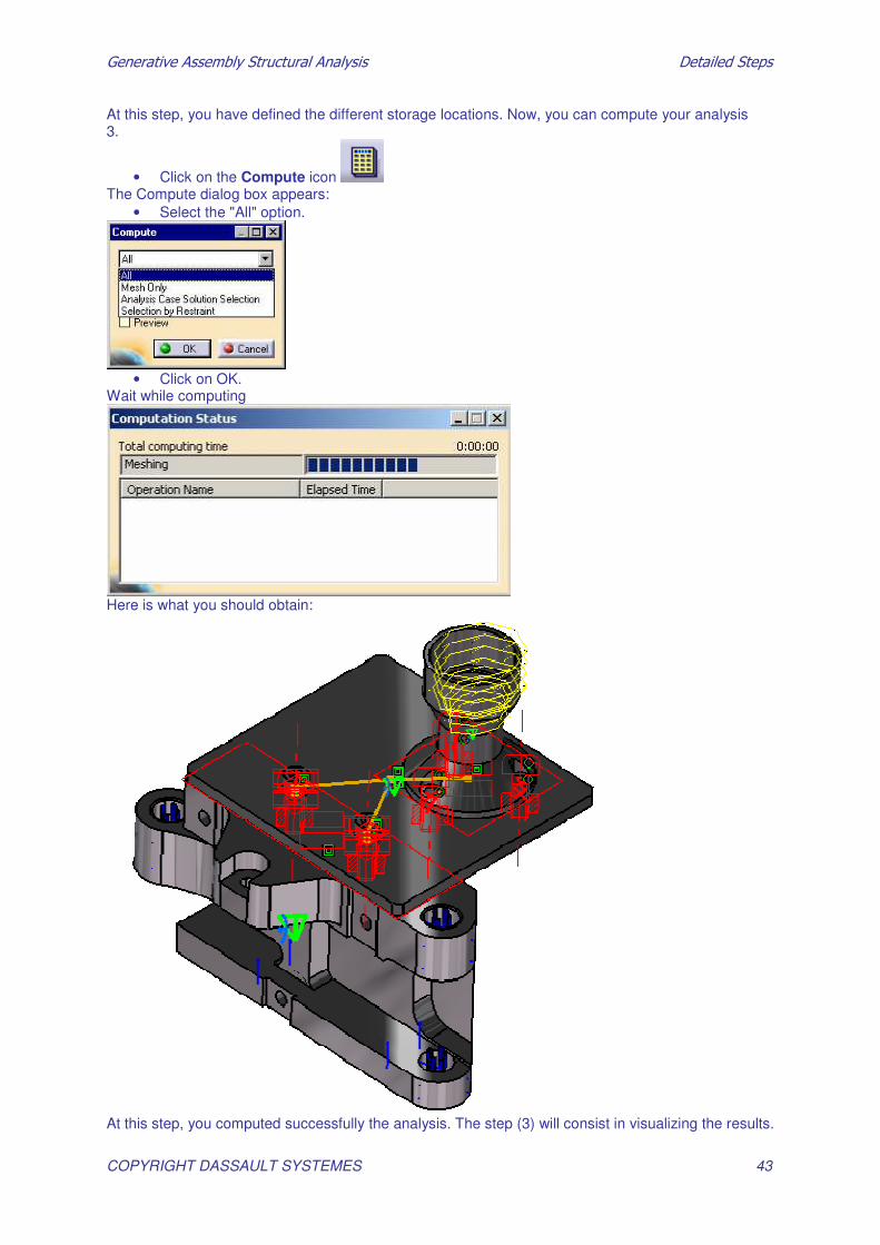
At this step, you have defined the different storage locations. Now, you can compute your analysis 3.
• Click on the Compute icon The Compute dialog box appears:
• Select the "All" option.
• Click on OK.
Wait while computing
Here is what you should obtain:
At this step, you computed successfully the analysis. The step (3) will consist in visualizing the results.

�������������� ������������������� �������������
COPYRIGHT DASSAULT SYSTEMES 44
3. Results Visualization
3.1 - Display the Von Mises Stress
Before you begin, hide all the connections, load, restraints.
1. Click on the Von Mises Stress icon
• Double-click on the Color Map
• Key 20 as number as colors
• Check the “imposed max” option • Impose 4e6
�������������� ������������������� �������������
COPYRIGHT DASSAULT SYSTEMES 45
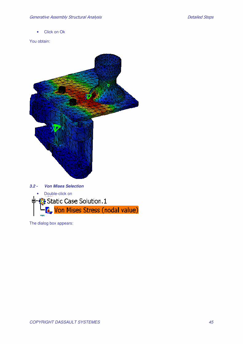
• Click on Ok You obtain:
3.2 - Von Mises Selection
• Double-click on
The dialog box appears:

�������������� ������������������� �������������
COPYRIGHT DASSAULT SYSTEMES 46
• Click on “Selections” tab
• Select these mesh-part:

�������������� ������������������� �������������
COPYRIGHT DASSAULT SYSTEMES 47
• Click on the down arrow button to push selected items in Activated group as shown
• Click on ok You obtain:

�������������� ������������������� �������������
COPYRIGHT DASSAULT SYSTEMES 48
3.3 - Von Mises Cutting plane
• Click on
• Drag the cutting plane using the compass • Un-check “show cutting plane”

�������������� ������������������� �������������
COPYRIGHT DASSAULT SYSTEMES 49
• Click on Close
4.
3.4 - Image Animation
• Click on the “Amplification Magnitude” icon
• Key 2.5 as scaling Factor • Click on Ok
• Click on the “Animate” icon
• Key 20 as number of steps • By clicking the “More” you can access more options.
�������������� ������������������� �������������
COPYRIGHT DASSAULT SYSTEMES 50
• Click on Ok where you are done • See step3_end.CATAnalysis for reference.
�������������� ������������������� �������������
COPYRIGHT DASSAULT SYSTEMES 51
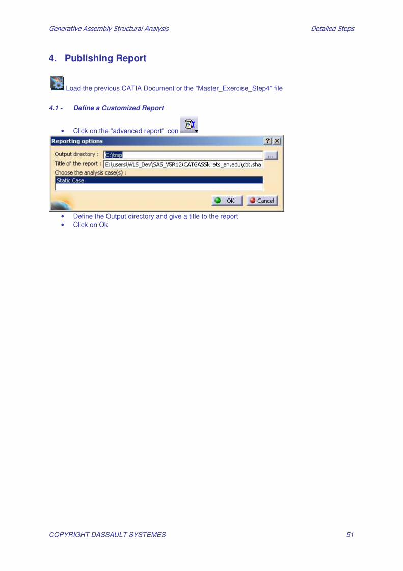
4. Publishing Report
Load the previous CATIA Document or the "Master_Exercise_Step4" file
4.1 - Define a Customized Report
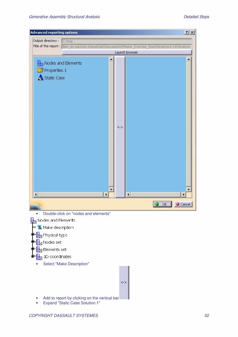
• Click on the "advanced report" icon
• Define the Output directory and give a title to the report • Click on Ok
�������������� ������������������� �������������
COPYRIGHT DASSAULT SYSTEMES 52
• Double-click on "nodes and elements"
• Select "Make Description"
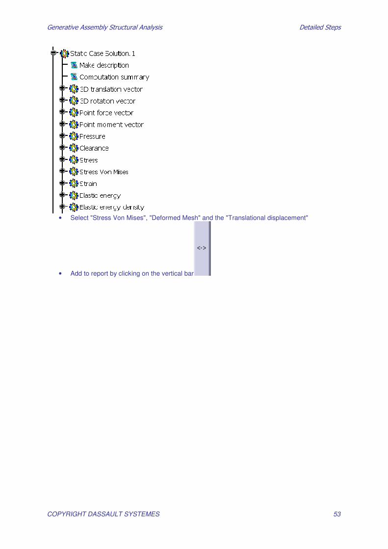
• Add to report by clicking on the vertical bar • Expand "Static Case Solution.1"
�������������� ������������������� �������������
COPYRIGHT DASSAULT SYSTEMES 53
• Select "Stress Von Mises", "Deformed Mesh" and the "Translational displacement"
• Add to report by clicking on the vertical bar

�������������� ������������������� �������������
COPYRIGHT DASSAULT SYSTEMES 54
• Click on Ok