healing assistant - freeyvonet.florent.free.fr/serveur/cours catia/catia...in such situations,...
TRANSCRIPT

Student Notes:
Healing Assistant������������
Copyright DASSAULT SYSTEMES 1
Cop
yrig
ht D
AS
SA
ULT
SY
ST
EM
ES
Healing Assistant
CATIA V5 TrainingFoils
Version 5 Release 19August 2008
EDU_CAT_EN_HA1_FF_V5R19
Student Notes:
Healing Assistant������������
Copyright DASSAULT SYSTEMES 2
Cop
yrig
ht D
AS
SA
ULT
SY
ST
EM
ES
About this courseObjectives of the courseUpon completion of this course you will be able to:- Analyze the imported data- Repair the imported data- Compare two versions of a Part- Customize the workbench
Targeted audienceTooling Designers, Mechanical Designers, Surface Designers.
PrerequisitesStudents attending this course should be familiar with the Wireframe and Surfaces.
1 day
Student Notes:
Healing Assistant������������
Copyright DASSAULT SYSTEMES 3
Cop
yrig
ht D
AS
SA
ULT
SY
ST
EM
ES
Table of Contents (1/2)
Introduction to Healing Assistant 5Why Do You Need Healing? 6Accessing the Workbench 7User Interface: Healing Assistant Editor 8Methodology For Healing 10Information On the Join Operator 11How To Choose a Merging Distance 15
Model Analysis 17Face Checker 18Face Orientation 20Geometrical Display 22Repairing Invalid Surfaces 23Face Smooth 24Surface Connection Checker 26Repairing Topology 28
Closing a Join Surface 29Checking For Free Sides 30Fixing Free Sides 32
Student Notes:
Healing Assistant������������
Copyright DASSAULT SYSTEMES 4
Cop
yrig
ht D
AS
SA
ULT
SY
ST
EM
ES
Table of Contents (2/2)
Local Join 34The Healing Operator 36Local Healing 37
Comparing Models 38Compare Parts 39
Customizing the Workbench 42IGES 3D Import 43CATIA V4 Import 50
Student Notes:
Healing Assistant������������
Copyright DASSAULT SYSTEMES 5
Cop
yrig
ht D
AS
SA
ULT
SY
ST
EM
ES
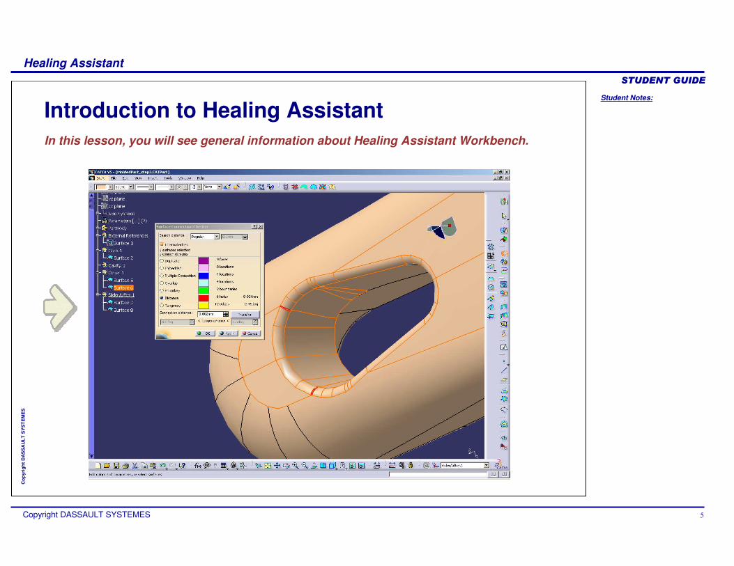
Introduction to Healing AssistantIn this lesson, you will see general information about Healing Assistant Workbench.
Student Notes:
Healing Assistant������������
Copyright DASSAULT SYSTEMES 6
Cop
yrig
ht D
AS
SA
ULT
SY
ST
EM
ES
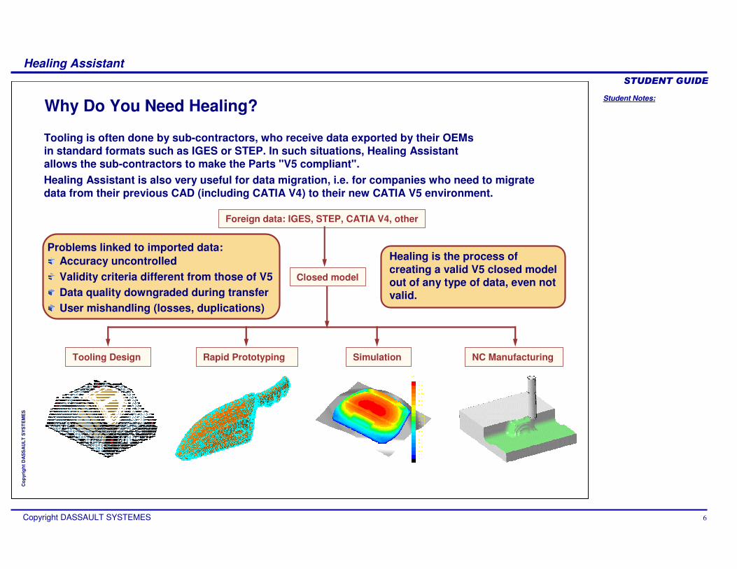
Why Do You Need Healing?
Healing is the process of creating a valid V5 closed model out of any type of data, even not valid.
Foreign data: IGES, STEP, CATIA V4, other
Closed model
Tooling Design NC ManufacturingRapid Prototyping Simulation
Problems linked to imported data:Accuracy uncontrolledValidity criteria different from those of V5Data quality downgraded during transferUser mishandling (losses, duplications)
Tooling is often done by sub-contractors, who receive data exported by their OEMs in standard formats such as IGES or STEP. In such situations, Healing Assistant allows the sub-contractors to make the Parts "V5 compliant".Healing Assistant is also very useful for data migration, i.e. for companies who need to migrate data from their previous CAD (including CATIA V4) to their new CATIA V5 environment.
Student Notes:
Healing Assistant������������
Copyright DASSAULT SYSTEMES 7
Cop
yrig
ht D
AS
SA
ULT
SY
ST
EM
ES
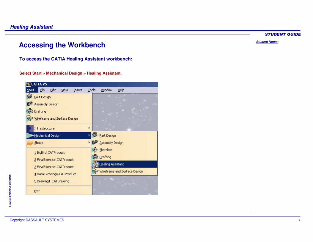
Accessing the Workbench
To access the CATIA Healing Assistant workbench:
Select Start > Mechanical Design > Healing Assistant.
Student Notes:
Healing Assistant������������
Copyright DASSAULT SYSTEMES 8
Cop
yrig
ht D
AS
SA
ULT
SY
ST
EM
ES
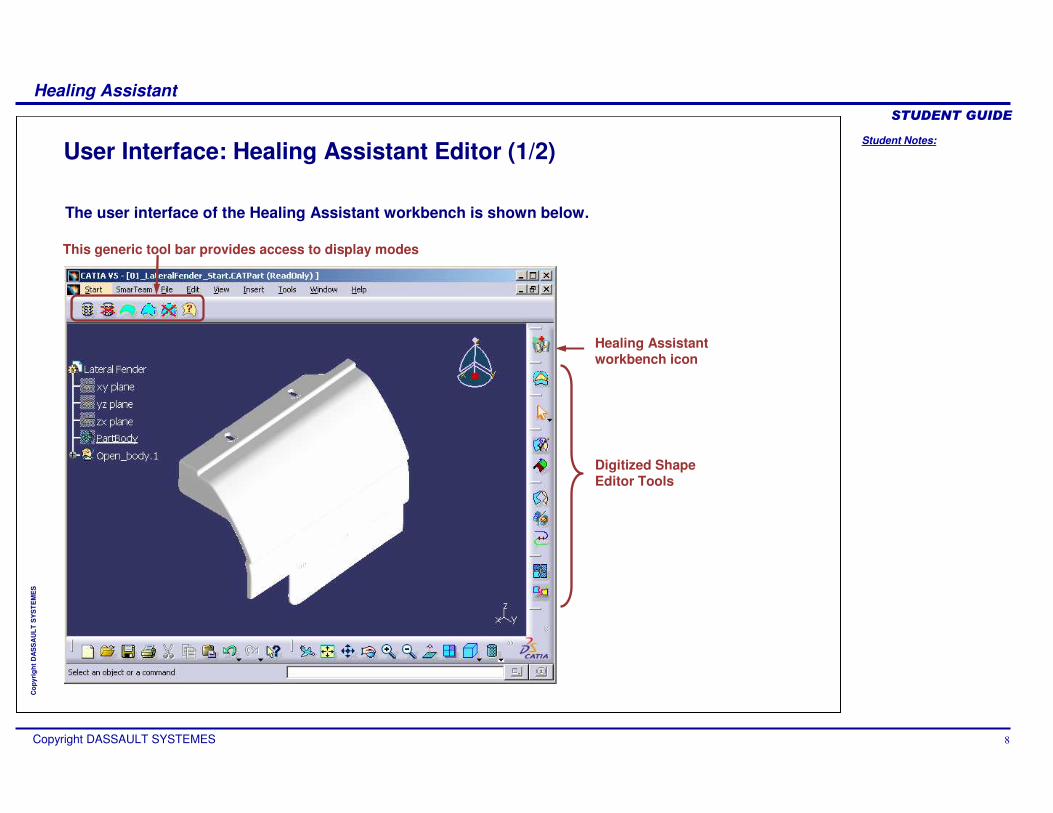
The user interface of the Healing Assistant workbench is shown below.
User Interface: Healing Assistant Editor (1/2)
Digitized Shape Editor Tools
Healing Assistant workbench icon
This generic tool bar provides access to display modes
Student Notes:
Healing Assistant������������
Copyright DASSAULT SYSTEMES 9
Cop
yrig
ht D
AS
SA
ULT
SY
ST
EM
ES
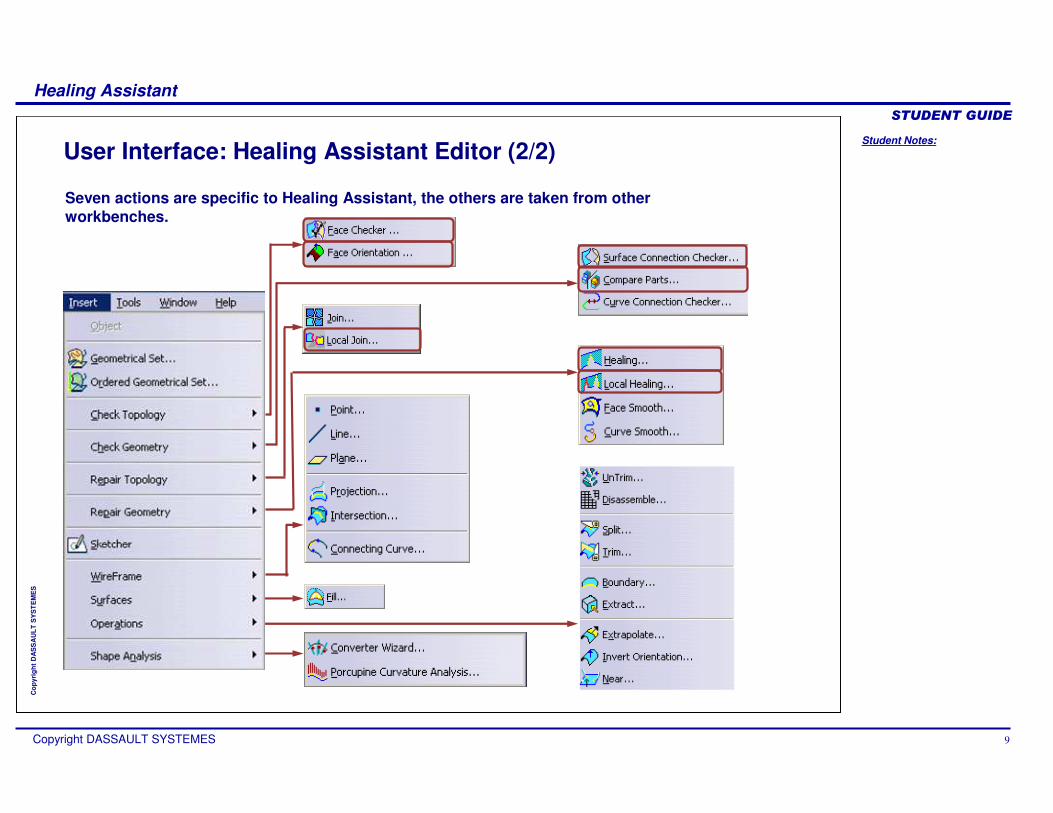
Seven actions are specific to Healing Assistant, the others are taken from other workbenches.
User Interface: Healing Assistant Editor (2/2)

Student Notes:
Healing Assistant������������
Copyright DASSAULT SYSTEMES 10
Cop
yrig
ht D
AS
SA
ULT
SY
ST
EM
ES
Check for bad topology situations
Repair bad topology situations
Repair invalid surfaces
Check all surfaces individually
Optional: clean all surface boundaries at once to simplify
the model.
Optional: measure the gaps between surfaces to evaluate the tolerance of the imported data.
Methodology For Healing
Prepare data: put all surfaces to join in a geometrical set, remove
unnecessary data.
Join all surfaces with a strict tolerance (for example 0.01mm).
Analyze free sides
Close free sides
Create solid
If invalid surfaces If join failure
If OK
General process for healing can be seen in the following flow chart.
Student Notes:
Healing Assistant������������
Copyright DASSAULT SYSTEMES 11
Cop
yrig
ht D
AS
SA
ULT
SY
ST
EM
ES
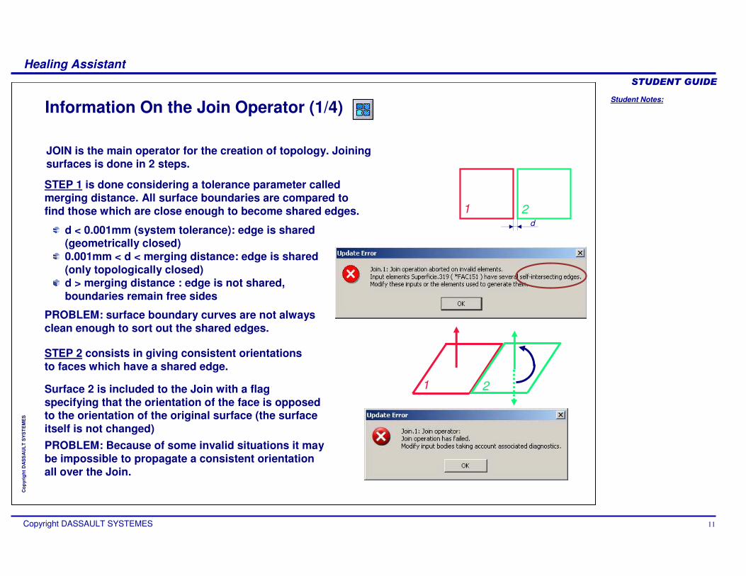
Information On the Join Operator (1/4)
Surface 2 is included to the Join with a flag specifying that the orientation of the face is opposed to the orientation of the original surface (the surface itself is not changed)
1 2
JOIN is the main operator for the creation of topology. Joining surfaces is done in 2 steps.
d < 0.001mm (system tolerance): edge is shared (geometrically closed)0.001mm < d < merging distance: edge is shared (only topologically closed)d > merging distance : edge is not shared, boundaries remain free sides
d
1 2
STEP 1 is done considering a tolerance parameter called merging distance. All surface boundaries are compared to find those which are close enough to become shared edges.
PROBLEM: surface boundary curves are not always clean enough to sort out the shared edges.
STEP 2 consists in giving consistent orientations to faces which have a shared edge.
PROBLEM: Because of some invalid situations it may be impossible to propagate a consistent orientation all over the Join.
Student Notes:
Healing Assistant������������
Copyright DASSAULT SYSTEMES 12
Cop
yrig
ht D
AS
SA
ULT
SY
ST
EM
ES
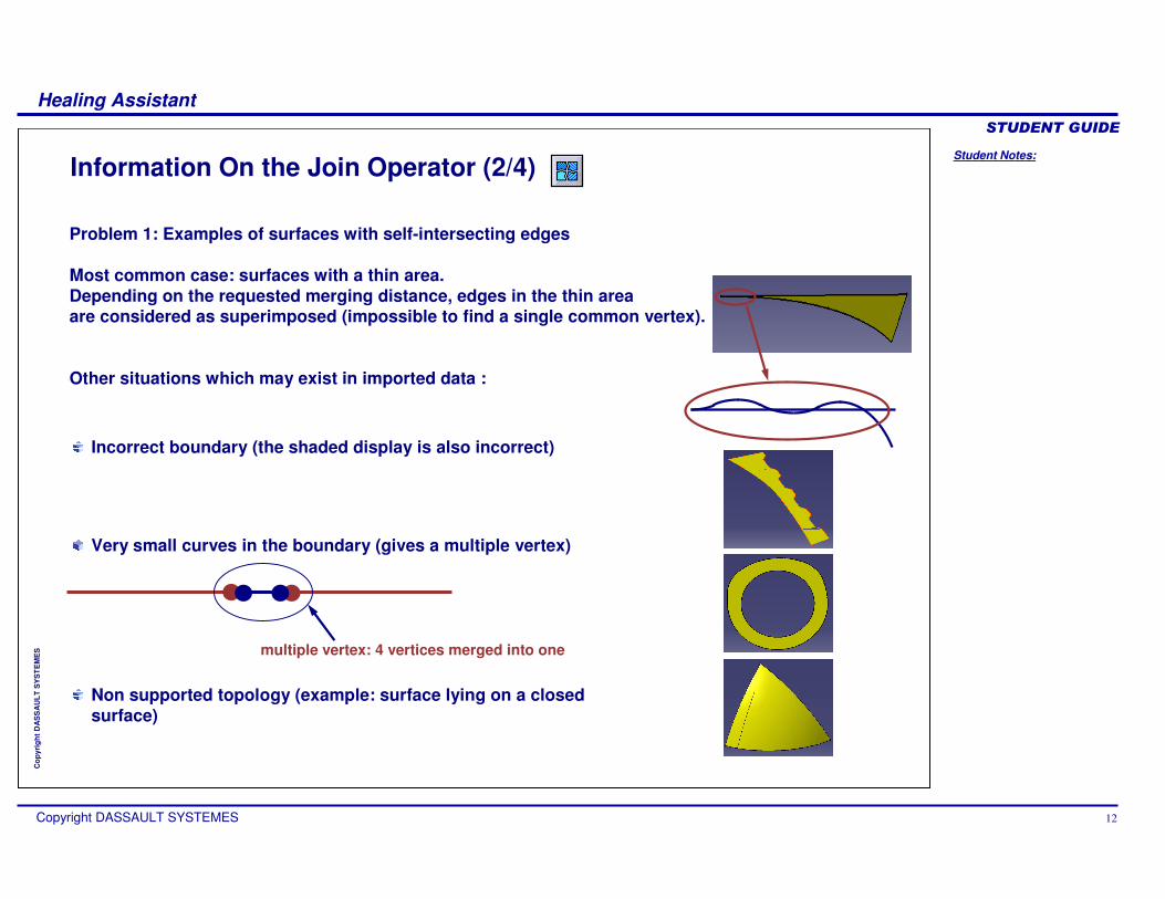
Information On the Join Operator (2/4)
Problem 1: Examples of surfaces with self-intersecting edges
Most common case: surfaces with a thin area.Depending on the requested merging distance, edges in the thin areaare considered as superimposed (impossible to find a single common vertex).
Other situations which may exist in imported data :
Incorrect boundary (the shaded display is also incorrect)
Non supported topology (example: surface lying on a closed surface)
Very small curves in the boundary (gives a multiple vertex)
multiple vertex: 4 vertices merged into one

Student Notes:
Healing Assistant������������
Copyright DASSAULT SYSTEMES 13
Cop
yrig
ht D
AS
SA
ULT
SY
ST
EM
ES
Information On the Join Operator (3/4)
1 2
3
1 2
3
expected orientation
“wrong” orientation
Impossible to find a consistent orientation except if the join operator manages to keep some edges as free sidesIn some cases you can get a result, if the Join operator has been able to keep superimposed edges as free edges (boundaries)
Two possible orientations for surface 2, if the “wrong” one is kept, it will not be possible to add surface 3 to the join.
Expected propagation Incorrect propagation
If possible the Join operator will show the location of orientation inversions; when it is impossible only Healing Assistant can help in finding the defects (usually non manifold edges).
Problem 2: Examples of Join failures
Case of duplicated or embedded surfaces
Case of small overlap

Student Notes:
Healing Assistant������������
Copyright DASSAULT SYSTEMES 14
Cop
yrig
ht D
AS
SA
ULT
SY
ST
EM
ES
Information On the Join Operator (4/4)
12
3
Impossible to find a consistent orientation except if the join operator manages to keep some edges as free sides.
Impossible to define a consistent orientation all over the surface except by keeping a free edge.
Moebius type situation:
No inside/outside definition is possible.
Problem 2: Examples of Join failures
Case of multiple connections:
Standard non manifold edge is edge shared by more than 2 faces.

Student Notes:
Healing Assistant������������
Copyright DASSAULT SYSTEMES 15
Cop
yrig
ht D
AS
SA
ULT
SY
ST
EM
ES
How To Choose a Merging Distance (1/2)
merging dist. = 0.001mm merging dist. = 0.01mm merging dist. = 0.1mm
Finally Join removes all edges which are smaller than the merging distance, which can cause problems if the merging distance is too high.
The suppression of small curves may later produce invalid faces (with self-intersecting edges).
You must take into account the accuracy of the data to Join: if you choose a strict tolerance, the Join has many free sides and it takes time to correct them.
Also sometimes Join does not work with a strict tolerance (Join failure).On the other hand when you relax the tolerance, some gaps are hidden but the geometry still has gaps and may be unusable for later processing .
For example gaps may cause visible marks on the manufactured partremember that a gap may be: or:
Student Notes:
Healing Assistant������������
Copyright DASSAULT SYSTEMES 16
Cop
yrig
ht D
AS
SA
ULT
SY
ST
EM
ES
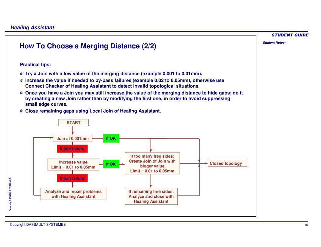
How To Choose a Merging Distance (2/2)
Join at 0.001mm
Increase valueLimit = 0.01 to 0.05mm
Analyze and repair problems with Healing Assistant
If too many free sides:Create Join of Join with
bigger valueLimit = 0.01 to 0.05mm
If remaining free sides:Analyze and close with
Healing Assistant
Closed topology
START
If join failure
If OK
If join failure
If OK
Practical tips:
Try a Join with a low value of the merging distance (example 0.001 to 0.01mm).Increase the value if needed to by-pass failures (example 0.02 to 0.05mm), otherwise use Connect Checker of Healing Assistant to detect invalid topological situations.Once you have a Join you may still increase the value of the merging distance to hide gaps; do it by creating a new Join rather than by modifying the first one, in order to avoid suppressing small edge curves.Close remaining gaps using Local Join of Healing Assistant.
Student Notes:
Healing Assistant������������
Copyright DASSAULT SYSTEMES 17
Cop
yrig
ht D
AS
SA
ULT
SY
ST
EM
ES
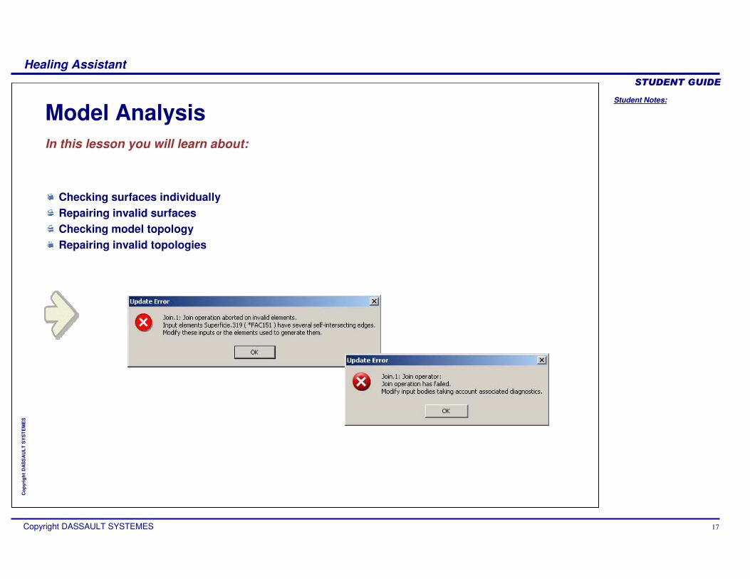
Model AnalysisIn this lesson you will learn about:
Checking surfaces individuallyRepairing invalid surfacesChecking model topologyRepairing invalid topologies

Student Notes:
Healing Assistant������������
Copyright DASSAULT SYSTEMES 18
Cop
yrig
ht D
AS
SA
ULT
SY
ST
EM
ES
Face Checker (1/2)
A. Check internal faces of multi-face surfaces; if the option is not checked only the outside boundaries are analyzed.
B. Tolerance for the detection of self-intersections: use the merging distance that you intend to use in the Join command.
C. Tolerance for the detection of holes (gaps) in surface boundaries: only surfaces with holes larger than the given value will be highlighted.
D. Tolerance for the detection of thin faces: faces are considered thin when their “width” is everywhere smaller than the specified value.
E. Transfer detected surfaces to a new geometrical set (see next page).
F. Color used for highlight of detected surfaces (you can double-click the color slab to change the color).
The purpose of the face checker is:To find surfaces with an invalid boundary for a given merging distance.To find surfaces with holes in their boundaries and thin surfaces. To sort the surfaces by moving the invalid ones to a new geometrical set.
A
C
D
E
F
B
WARNING: checking all surfaces with Face Checker and removing the surfaces detected invalid does not ensure that the Join operator will succeed. New invalidities may appear during the Join process itself.
Student Notes:
Healing Assistant������������
Copyright DASSAULT SYSTEMES 19
Cop
yrig
ht D
AS
SA
ULT
SY
ST
EM
ES
Face Checker (2/2)
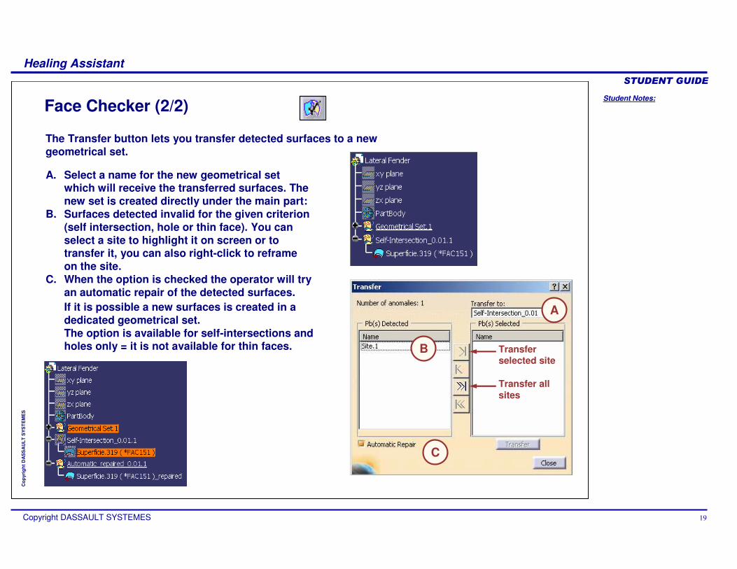
The Transfer button lets you transfer detected surfaces to a newgeometrical set.
A. Select a name for the new geometrical set which will receive the transferred surfaces. The new set is created directly under the main part:
B. Surfaces detected invalid for the given criterion (self intersection, hole or thin face). You can select a site to highlight it on screen or to transfer it, you can also right-click to reframe on the site.
C. When the option is checked the operator will try an automatic repair of the detected surfaces.If it is possible a new surfaces is created in a dedicated geometrical set.The option is available for self-intersections and holes only = it is not available for thin faces.
A
C
B Transfer selected site
Transfer all sites
Student Notes:
Healing Assistant������������
Copyright DASSAULT SYSTEMES 20
Cop
yrig
ht D
AS
SA
ULT
SY
ST
EM
ES
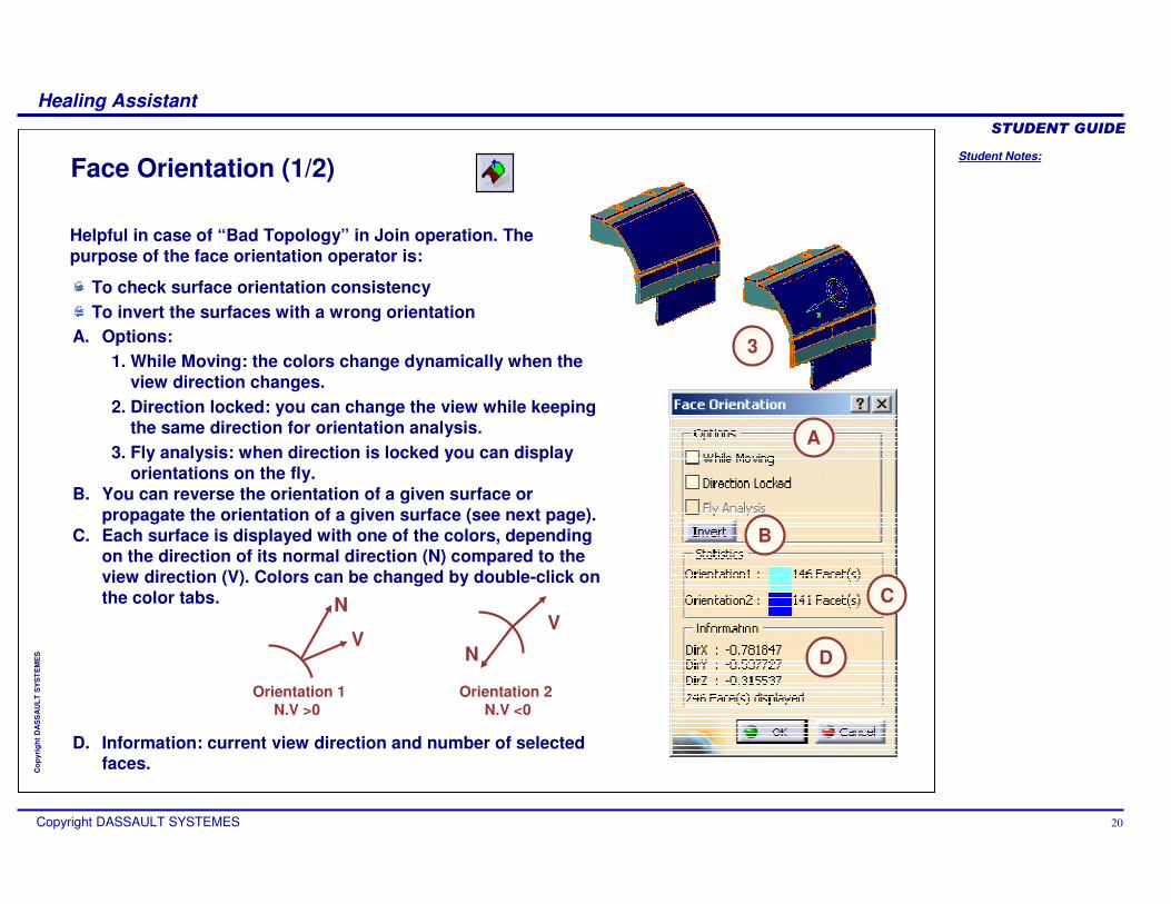
A. Options:1. While Moving: the colors change dynamically when the
view direction changes.2. Direction locked: you can change the view while keeping
the same direction for orientation analysis.3. Fly analysis: when direction is locked you can display
orientations on the fly.B. You can reverse the orientation of a given surface or
propagate the orientation of a given surface (see next page).C. Each surface is displayed with one of the colors, depending
on the direction of its normal direction (N) compared to the view direction (V). Colors can be changed by double-click on the color tabs.
D. Information: current view direction and number of selected faces.
Face Orientation (1/2)
Helpful in case of “Bad Topology” in Join operation. The purpose of the face orientation operator is:
To check surface orientation consistency To invert the surfaces with a wrong orientation
Orientation 1 Orientation 2N.V >0 N.V <0
N
VN
V
3
C
D
B
A

Student Notes:
Healing Assistant������������
Copyright DASSAULT SYSTEMES 21
Cop
yrig
ht D
AS
SA
ULT
SY
ST
EM
ES
Face Orientation (2/2)
A. Manual: Only some selected surfaces are inverted.
B. Automatic: The orientation of a selected surface is propagated to all other surfaces of the selection (consistent orientation).
a. Options: same as Connect Checker.b. Search distance: distance used to pre-select boundary
edges that will be compared (edges candidate for merging).c. Connection distance: distance below which two candidate
edges are actually considered as merged and the orientation is propagated.
Invert surface
The processed surfaces are hidden and the new surfaces (with inverted orientations) are created in a new Geometrical Set.
BA
Student Notes:
Healing Assistant������������
Copyright DASSAULT SYSTEMES 22
Cop
yrig
ht D
AS
SA
ULT
SY
ST
EM
ES
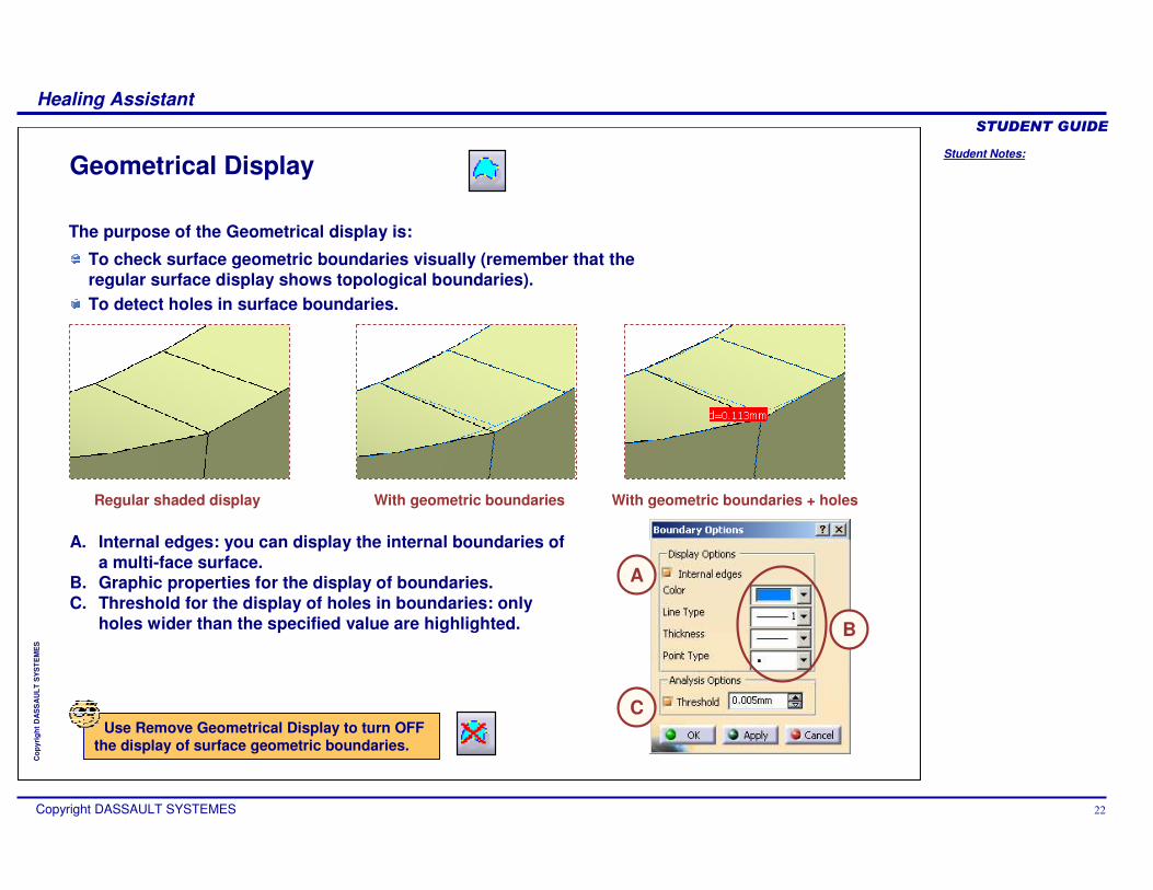
Regular shaded display With geometric boundaries With geometric boundaries + holes
A. Internal edges: you can display the internal boundaries of a multi-face surface.
B. Graphic properties for the display of boundaries.C. Threshold for the display of holes in boundaries: only
holes wider than the specified value are highlighted.
The purpose of the Geometrical display is:
To check surface geometric boundaries visually (remember that the regular surface display shows topological boundaries).To detect holes in surface boundaries.
Use Remove Geometrical Display to turn OFF the display of surface geometric boundaries.
C
B
A
Geometrical Display

Student Notes:
Healing Assistant������������
Copyright DASSAULT SYSTEMES 23
Cop
yrig
ht D
AS
SA
ULT
SY
ST
EM
ES
Simple situations: replace the surface by a new element
FILL
MULTISECTIONS SURFACE or
BLEND (specially for ruled surfaces)
Repairing Invalid Surfaces
General case: recreate the surface by SPLIT
Isolate the invalid elementCreate its full BOUNDARY (as a datum)
If necessary:SMOOTH CURVE to the boundary
DISASSEMBLE the boundary, check and repair the curves and
JOIN them back
UNTRIM the surface
SPLIT the surface back.
You can repair invalid elements by one of these methods: Recreate by Split using the boundary and support surface of the invalid surface. In particular cases, it may be quicker to discard the invalid surface and to create a new one using the standard surface creation tools of CATIA.
Repairing the invalid elements is usually very easy and quick once they have been located.
Student Notes:
Healing Assistant������������
Copyright DASSAULT SYSTEMES 24
Cop
yrig
ht D
AS
SA
ULT
SY
ST
EM
ES
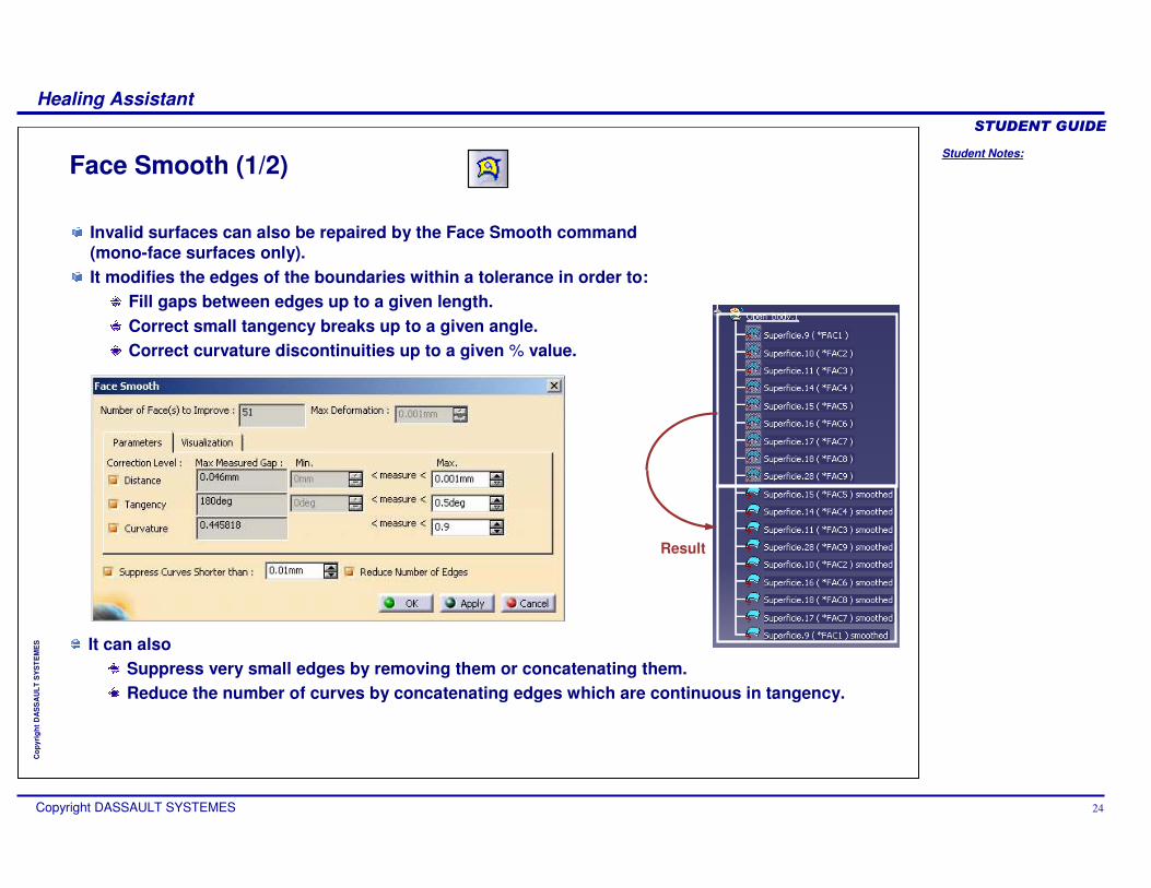
Face Smooth (1/2)
Invalid surfaces can also be repaired by the Face Smooth command(mono-face surfaces only).It modifies the edges of the boundaries within a tolerance in order to:
Fill gaps between edges up to a given length.Correct small tangency breaks up to a given angle.Correct curvature discontinuities up to a given % value.
It can also Suppress very small edges by removing them or concatenating them.Reduce the number of curves by concatenating edges which are continuous in tangency.
Result
Student Notes:
Healing Assistant������������
Copyright DASSAULT SYSTEMES 25
Cop
yrig
ht D
AS
SA
ULT
SY
ST
EM
ES
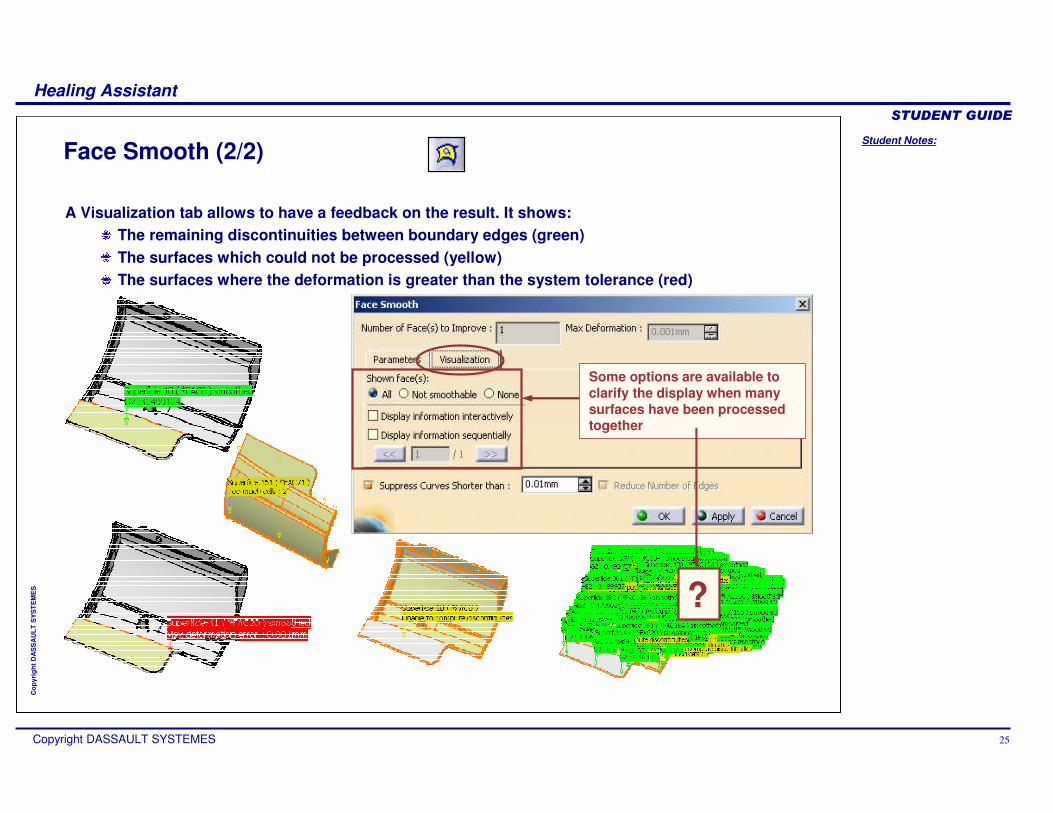
Face Smooth (2/2)
Some options are available to clarify the display when many surfaces have been processed together
?
A Visualization tab allows to have a feedback on the result. It shows:The remaining discontinuities between boundary edges (green)The surfaces which could not be processed (yellow)The surfaces where the deformation is greater than the system tolerance (red)
Student Notes:
Healing Assistant������������
Copyright DASSAULT SYSTEMES 26
Cop
yrig
ht D
AS
SA
ULT
SY
ST
EM
ES
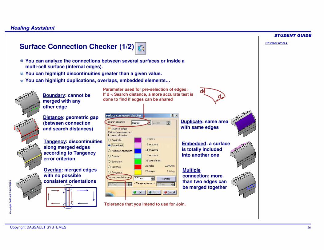
Surface Connection Checker (1/2)
Parameter used for pre-selection of edges:If d < Search distance, a more accurate test is done to find if edges can be shared d
d
Tolerance that you intend to use for Join.
Distance: geometric gap (between connection and search distances)
Multiple connection: more than two edges can be merged together
Embedded: a surface is totally included into another one
Boundary: cannot be merged with any other edge
Overlap: merged edges with no possible consistent orientations
Tangency: discontinuities along merged edges according to Tangency error criterion
Duplicate: same area with same edges
You can analyze the connections between several surfaces or inside a multi-cell surface (internal edges).You can highlight discontinuities greater than a given value. You can highlight duplications, overlaps, embedded elements…

Student Notes:
Healing Assistant������������
Copyright DASSAULT SYSTEMES 27
Cop
yrig
ht D
AS
SA
ULT
SY
ST
EM
ES
Surface Connection Checker (2/2)
A. Domain: domain number for the selected site
B. Value: distance, angle, number of merged edges depending on the type of analysis performed
Discontinuities are identified as sites grouped into connex domains.You can highlight a site and use Reframe to analyze it.You can transfer sites to a new geometrical set for later analysis.
Transfer selected site
Transfer all sites
BA
Student Notes:
Healing Assistant������������
Copyright DASSAULT SYSTEMES 28
Cop
yrig
ht D
AS
SA
ULT
SY
ST
EM
ES
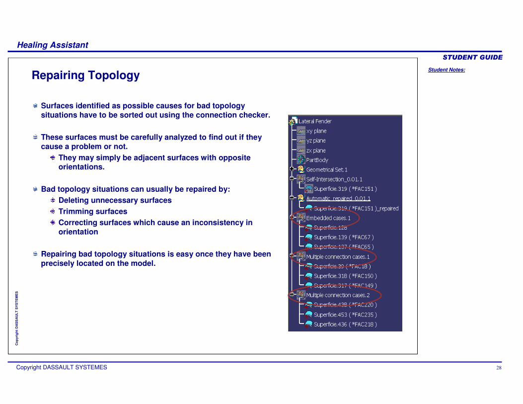
Repairing Topology
Surfaces identified as possible causes for bad topology situations have to be sorted out using the connection checker.
These surfaces must be carefully analyzed to find out if they cause a problem or not.
They may simply be adjacent surfaces with opposite orientations.
Bad topology situations can usually be repaired by: Deleting unnecessary surfacesTrimming surfaces Correcting surfaces which cause an inconsistency in orientation
Repairing bad topology situations is easy once they have been precisely located on the model.

Student Notes:
Healing Assistant������������
Copyright DASSAULT SYSTEMES 29
Cop
yrig
ht D
AS
SA
ULT
SY
ST
EM
ES
Closing a Join SurfaceOnce you have created a topology you have to make it closed (watertight, seamless). For that you need to analyze and suppress all free sides.
Example: molded part
Example: die face
solid created by Close Surface
solid created by Split or Pad/Up to surface
Student Notes:
Healing Assistant������������
Copyright DASSAULT SYSTEMES 30
Cop
yrig
ht D
AS
SA
ULT
SY
ST
EM
ES
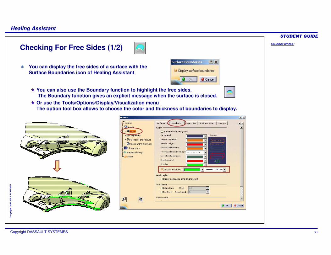
You can also use the Boundary function to highlight the free sides. The Boundary function gives an explicit message when the surface is closed.
Or use the Tools/Options/Display/Visualization menu The option tool box allows to choose the color and thickness of boundaries to display.
Checking For Free Sides (1/2)
You can display the free sides of a surface with the Surface Boundaries icon of Healing Assistant
Student Notes:
Healing Assistant������������
Copyright DASSAULT SYSTEMES 31
Cop
yrig
ht D
AS
SA
ULT
SY
ST
EM
ES
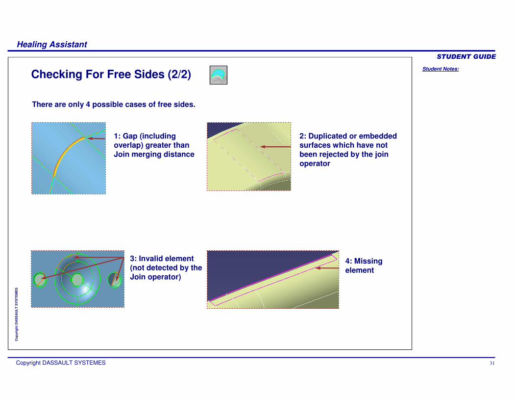
Checking For Free Sides (2/2)
2: Duplicated or embedded surfaces which have not been rejected by the join operator
1: Gap (including overlap) greater than Join merging distance
4: Missing element
3: Invalid element (not detected by the Join operator)
There are only 4 possible cases of free sides.

Student Notes:
Healing Assistant������������
Copyright DASSAULT SYSTEMES 32
Cop
yrig
ht D
AS
SA
ULT
SY
ST
EM
ES
Fixing Free Sides (1/2)
Missing elements, duplications and invalid elements are easy to correct once they are located.
Missing element: you can create missing elements by Fill or any other surface creation tool.
Duplicated or embedded element: just remove the unnecessary element from the topology and delete it. As unnecessary copies of duplicated elements are included to the Join as non connex domain, you can also use the Near operator to eliminate all the unwanted non connex domains in one shot.
Invalid element: remove the invalid element from the topology and recreate it with Fill or any other surface creation tool.
Student Notes:
Healing Assistant������������
Copyright DASSAULT SYSTEMES 33
Cop
yrig
ht D
AS
SA
ULT
SY
ST
EM
ES
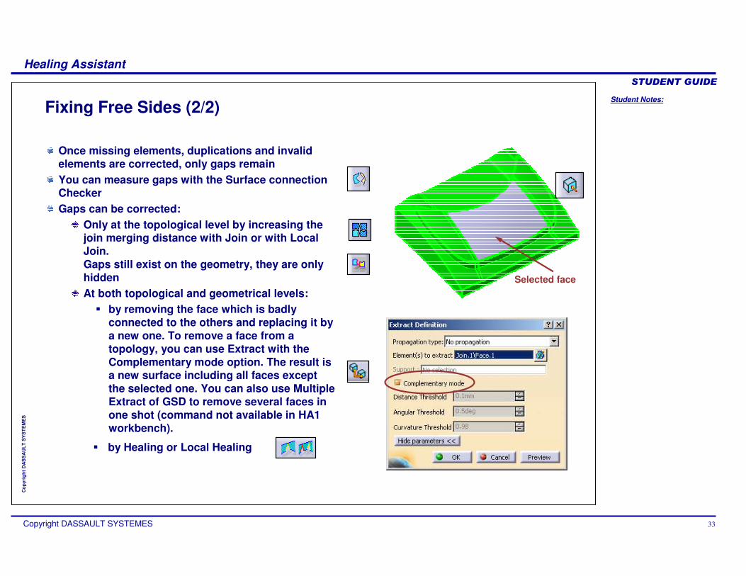
Once missing elements, duplications and invalid elements are corrected, only gaps remainYou can measure gaps with the Surface connection CheckerGaps can be corrected:
Only at the topological level by increasing the join merging distance with Join or with Local Join.Gaps still exist on the geometry, they are only hiddenAt both topological and geometrical levels:
� by removing the face which is badly connected to the others and replacing it by a new one. To remove a face from a topology, you can use Extract with the Complementary mode option. The result is a new surface including all faces except the selected one. You can also use Multiple Extract of GSD to remove several faces in one shot (command not available in HA1 workbench).
Fixing Free Sides (2/2)
Selected face
� by Healing or Local Healing
Student Notes:
Healing Assistant������������
Copyright DASSAULT SYSTEMES 34
Cop
yrig
ht D
AS
SA
ULT
SY
ST
EM
ES
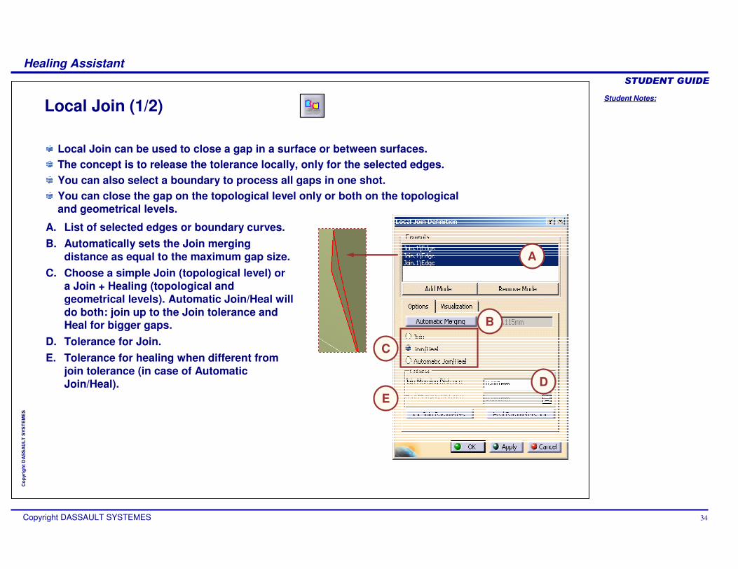
Local Join (1/2)
Local Join can be used to close a gap in a surface or between surfaces.The concept is to release the tolerance locally, only for the selected edges.You can also select a boundary to process all gaps in one shot.You can close the gap on the topological level only or both on the topological and geometrical levels.
A. List of selected edges or boundary curves.B. Automatically sets the Join merging
distance as equal to the maximum gap size.C. Choose a simple Join (topological level) or
a Join + Healing (topological and geometrical levels). Automatic Join/Heal will do both: join up to the Join tolerance and Heal for bigger gaps.
D. Tolerance for Join.E. Tolerance for healing when different from
join tolerance (in case of Automatic Join/Heal).
A
C
DE
B
Student Notes:
Healing Assistant������������
Copyright DASSAULT SYSTEMES 35
Cop
yrig
ht D
AS
SA
ULT
SY
ST
EM
ES
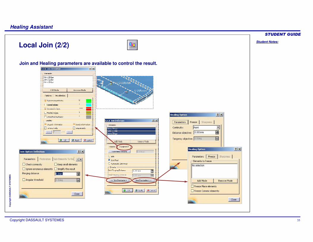
Local Join (2/2)
Join and Healing parameters are available to control the result.

Student Notes:
Healing Assistant������������
Copyright DASSAULT SYSTEMES 36
Cop
yrig
ht D
AS
SA
ULT
SY
ST
EM
ES
The concept of Healing is to measure connections between faces (same as Join) and to modify the faces when the distance is not within a given tolerance (merging distance).The distance is reduced to the user specified Distance Objective.Healing = Join + modification of surfaces to close geometry at shared edges.
The Healing Operator
surfaces with a gap a smart modification is applied to both surfacesa new common edge is computed
The process is totally automatic: the whole surface is processed.HEALING fills gaps but can also make surfaces tangent (G1), this can be useful for offset surfacesThe deformation preserves the shape tendency.Specific faces can be frozen so that they are not deformed (examples: planar faces, canonic shapes).
• d < 0.001mm (system tolerance): both geometry and topology are closed.
• 0.001mm < d < merging distance: the geometry is not closed but the topology is closed => HEALING modifies the surfaces to closethe geometry.
• d > merging distance : the geometry is not closed but HEALING does not modify anything because the topology is also not closed.
d
1 2
Student Notes:
Healing Assistant������������
Copyright DASSAULT SYSTEMES 37
Cop
yrig
ht D
AS
SA
ULT
SY
ST
EM
ES
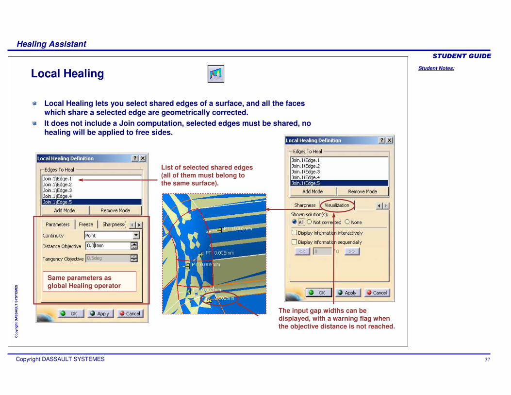
Local Healing
Same parameters as global Healing operator
The input gap widths can be displayed, with a warning flag when the objective distance is not reached.
List of selected shared edges (all of them must belong to the same surface).
Local Healing lets you select shared edges of a surface, and all the faces which share a selected edge are geometrically corrected.It does not include a Join computation, selected edges must be shared, no healing will be applied to free sides.

Student Notes:
Healing Assistant������������
Copyright DASSAULT SYSTEMES 38
Cop
yrig
ht D
AS
SA
ULT
SY
ST
EM
ES
Comparing Models
In this lesson, you will learn about:
Comparing two versions of a part.Finding differences between them.Sorting out the unchanged and the modified areas of the part.
Student Notes:
Healing Assistant������������
Copyright DASSAULT SYSTEMES 39
Cop
yrig
ht D
AS
SA
ULT
SY
ST
EM
ES
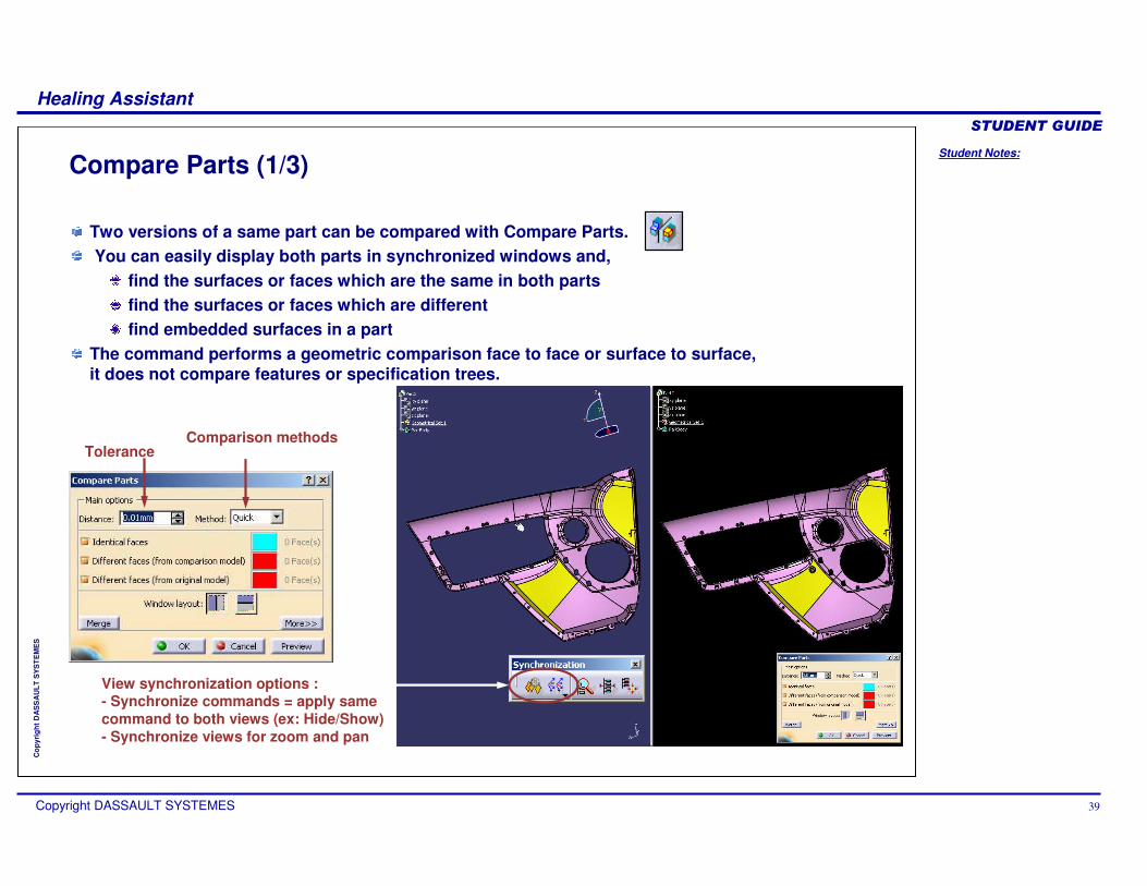
Two versions of a same part can be compared with Compare Parts.You can easily display both parts in synchronized windows and,
find the surfaces or faces which are the same in both partsfind the surfaces or faces which are differentfind embedded surfaces in a part
The command performs a geometric comparison face to face or surface to surface, it does not compare features or specification trees.
Compare Parts (1/3)
Tolerance
View synchronization options :- Synchronize commands = apply same command to both views (ex: Hide/Show)- Synchronize views for zoom and pan
Comparison methods
Student Notes:
Healing Assistant������������
Copyright DASSAULT SYSTEMES 40
Cop
yrig
ht D
AS
SA
ULT
SY
ST
EM
ES
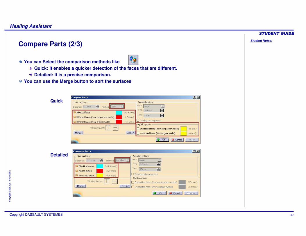
Compare Parts (2/3)
You can Select the comparison methods likeQuick: It enables a quicker detection of the faces that are different. Detailed: It is a precise comparison.
You can use the Merge button to sort the surfaces
Detailed
Quick
Student Notes:
Healing Assistant������������
Copyright DASSAULT SYSTEMES 41
Cop
yrig
ht D
AS
SA
ULT
SY
ST
EM
ES
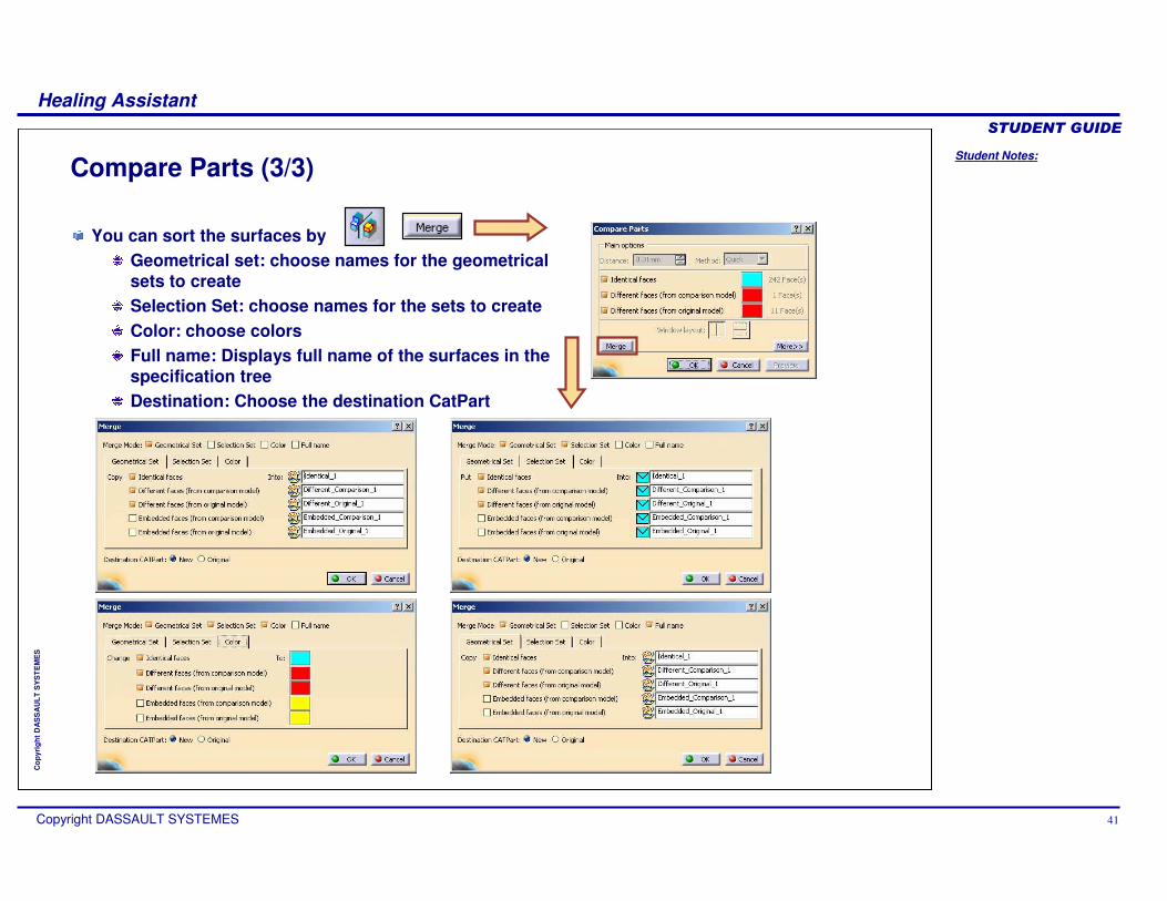
You can sort the surfaces byGeometrical set: choose names for the geometricalsets to createSelection Set: choose names for the sets to createColor: choose colorsFull name: Displays full name of the surfaces in thespecification treeDestination: Choose the destination CatPart
Compare Parts (3/3)
Student Notes:
Healing Assistant������������
Copyright DASSAULT SYSTEMES 42
Cop
yrig
ht D
AS
SA
ULT
SY
ST
EM
ES
Customizing the Workbench
You will learn about:
Controlling and improving the results of IGES 3D import.Controlling and improving the results of CATIA V4 import.
Student Notes:
Healing Assistant������������
Copyright DASSAULT SYSTEMES 43
Cop
yrig
ht D
AS
SA
ULT
SY
ST
EM
ES
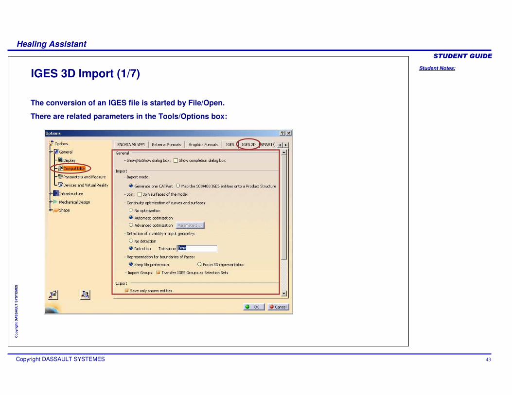
IGES 3D Import (1/7)
The conversion of an IGES file is started by File/Open.
There are related parameters in the Tools/Options box:
Student Notes:
Healing Assistant������������
Copyright DASSAULT SYSTEMES 44
Cop
yrig
ht D
AS
SA
ULT
SY
ST
EM
ES
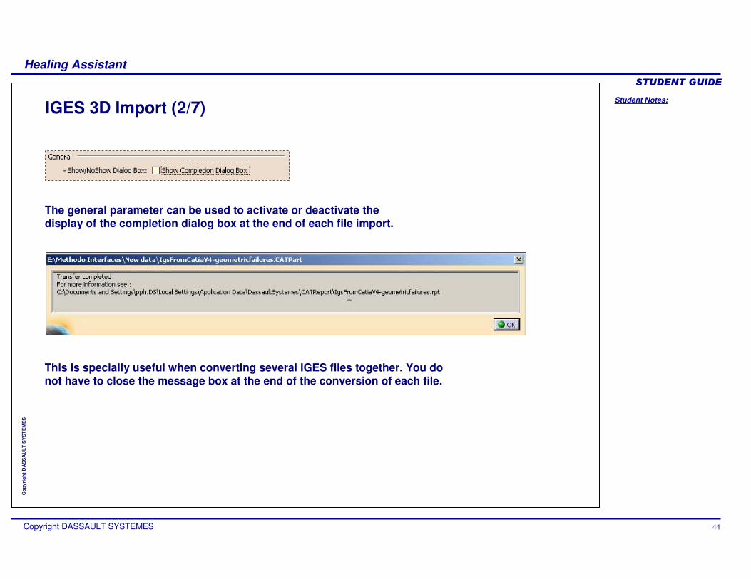
IGES 3D Import (2/7)
This is specially useful when converting several IGES files together. You do not have to close the message box at the end of the conversion of each file.
The general parameter can be used to activate or deactivate the display of the completion dialog box at the end of each file import.
Student Notes:
Healing Assistant������������
Copyright DASSAULT SYSTEMES 45
Cop
yrig
ht D
AS
SA
ULT
SY
ST
EM
ES
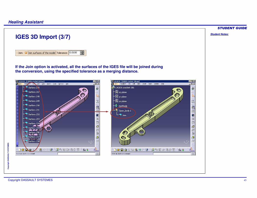
IGES 3D Import (3/7)
If the Join option is activated, all the surfaces of the IGES file will be joined during the conversion, using the specified tolerance as a merging distance.
Student Notes:
Healing Assistant������������
Copyright DASSAULT SYSTEMES 46
Cop
yrig
ht D
AS
SA
ULT
SY
ST
EM
ES
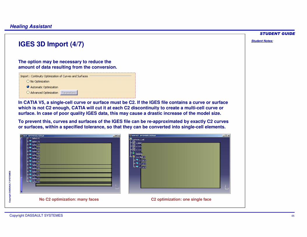
IGES 3D Import (4/7)
The option may be necessary to reduce the amount of data resulting from the conversion.
In CATIA V5, a single-cell curve or surface must be C2. If the IGES file contains a curve or surface which is not C2 enough, CATIA will cut it at each C2 discontinuity to create a multi-cell curve or surface. In case of poor quality IGES data, this may cause a drastic increase of the model size.
To prevent this, curves and surfaces of the IGES file can be re-approximated by exactly C2 curves or surfaces, within a specified tolerance, so that they can be converted into single-cell elements.
No C2 optimization: many faces C2 optimization: one single face
Student Notes:
Healing Assistant������������
Copyright DASSAULT SYSTEMES 47
Cop
yrig
ht D
AS
SA
ULT
SY
ST
EM
ES
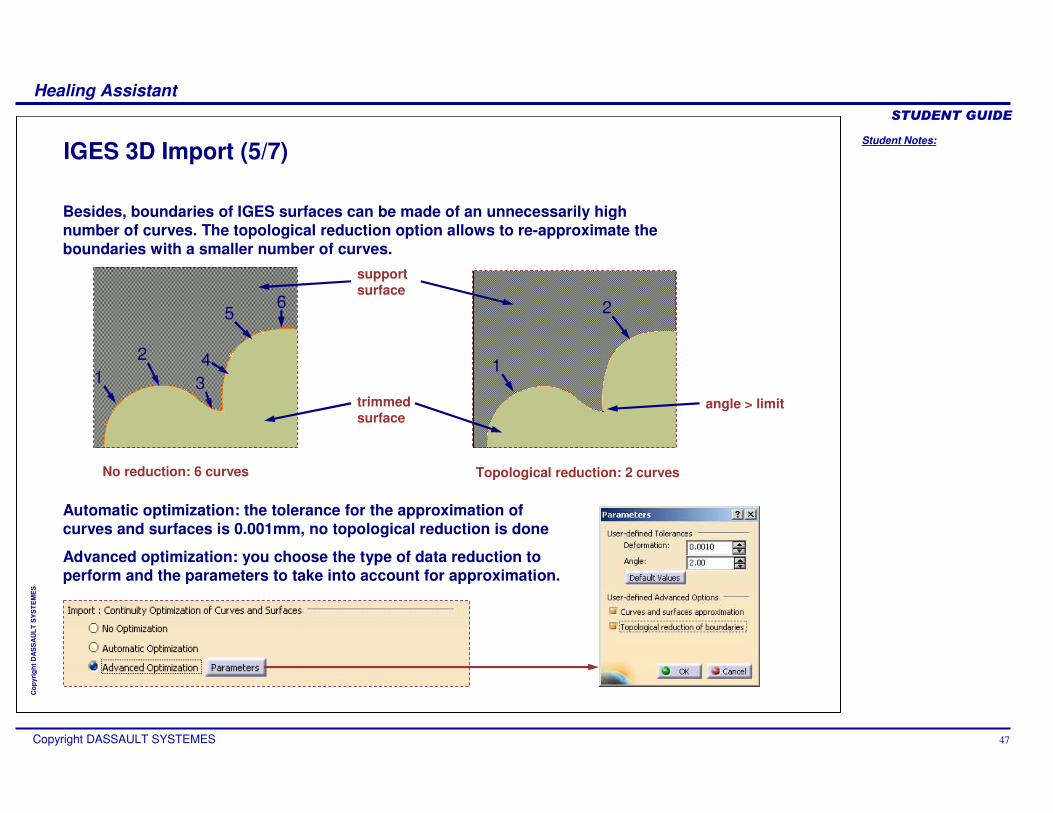
IGES 3D Import (5/7)
Besides, boundaries of IGES surfaces can be made of an unnecessarily high number of curves. The topological reduction option allows to re-approximate the boundaries with a smaller number of curves.
No reduction: 6 curves Topological reduction: 2 curves
12
34
56
1
2
trimmedsurface
supportsurface
angle > limit
Automatic optimization: the tolerance for the approximation of curves and surfaces is 0.001mm, no topological reduction is done
Advanced optimization: you choose the type of data reduction to perform and the parameters to take into account for approximation.
Student Notes:
Healing Assistant������������
Copyright DASSAULT SYSTEMES 48
Cop
yrig
ht D
AS
SA
ULT
SY
ST
EM
ES
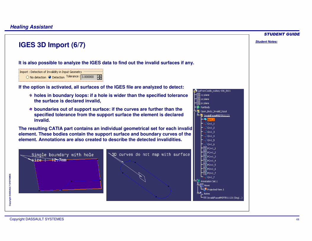
IGES 3D Import (6/7)
If the option is activated, all surfaces of the IGES file are analyzed to detect:
holes in boundary loops: if a hole is wider than the specified tolerance the surface is declared invalid,
boundaries out of support surface: if the curves are further than the specified tolerance from the support surface the element is declared invalid.
The resulting CATIA part contains an individual geometrical set for each invalid element. These bodies contain the support surface and boundary curves of the element. Annotations are also created to describe the detected invalidities.
It is also possible to analyze the IGES data to find out the invalid surfaces if any.
Student Notes:
Healing Assistant������������
Copyright DASSAULT SYSTEMES 49
Cop
yrig
ht D
AS
SA
ULT
SY
ST
EM
ES
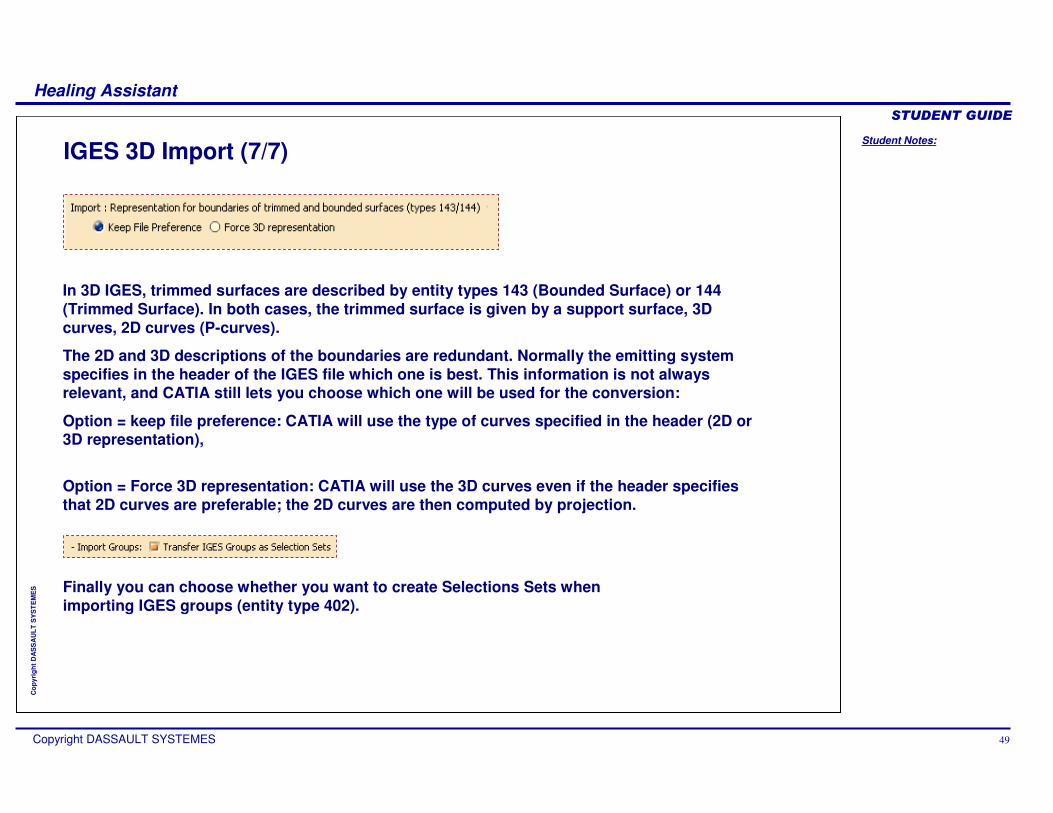
IGES 3D Import (7/7)
In 3D IGES, trimmed surfaces are described by entity types 143 (Bounded Surface) or 144 (Trimmed Surface). In both cases, the trimmed surface is given by a support surface, 3D curves, 2D curves (P-curves).
The 2D and 3D descriptions of the boundaries are redundant. Normally the emitting system specifies in the header of the IGES file which one is best. This information is not always relevant, and CATIA still lets you choose which one will be used for the conversion:
Option = keep file preference: CATIA will use the type of curves specified in the header (2D or 3D representation),
Option = Force 3D representation: CATIA will use the 3D curves even if the header specifies that 2D curves are preferable; the 2D curves are then computed by projection.
Finally you can choose whether you want to create Selections Sets when importing IGES groups (entity type 402).
Student Notes:
Healing Assistant������������
Copyright DASSAULT SYSTEMES 50
Cop
yrig
ht D
AS
SA
ULT
SY
ST
EM
ES
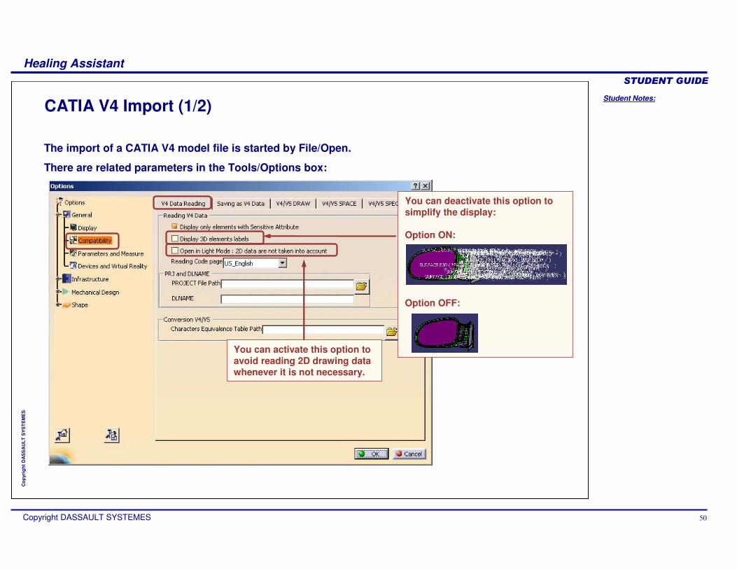
CATIA V4 Import (1/2)
You can deactivate this option to simplify the display:
Option ON:
Option OFF:
You can activate this option to avoid reading 2D drawing data whenever it is not necessary.
The import of a CATIA V4 model file is started by File/Open.
There are related parameters in the Tools/Options box:
Student Notes:
Healing Assistant������������
Copyright DASSAULT SYSTEMES 51
Cop
yrig
ht D
AS
SA
ULT
SY
ST
EM
ES
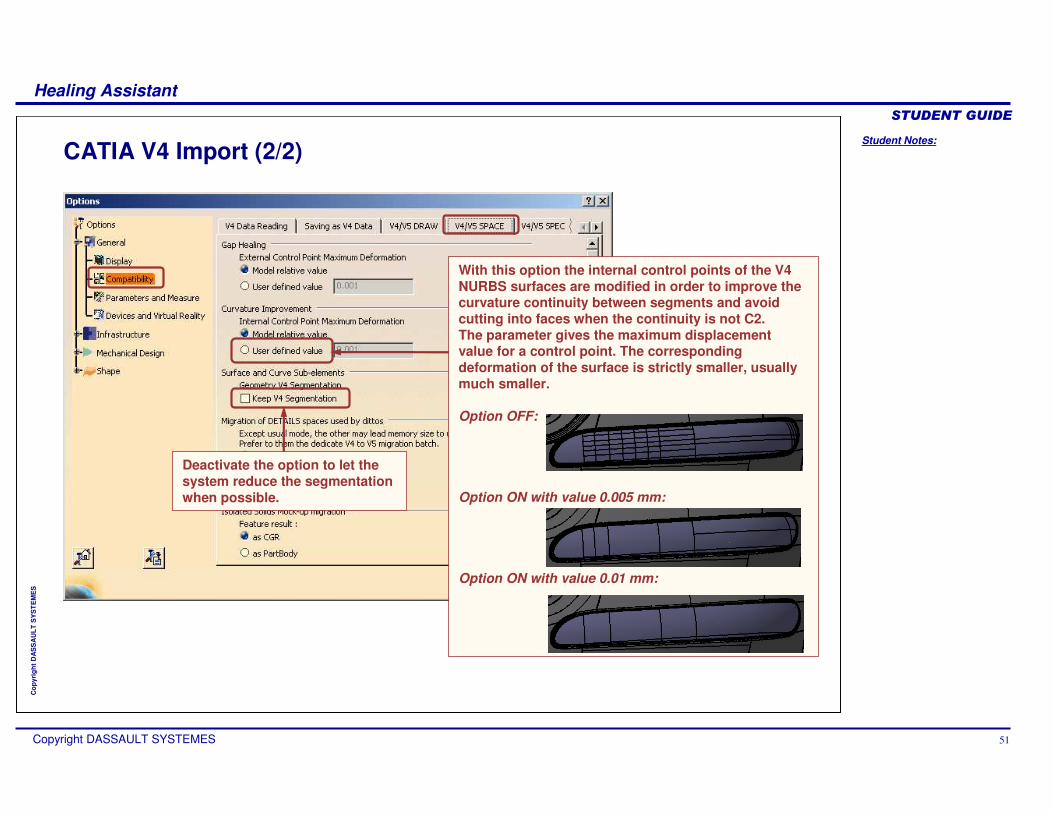
CATIA V4 Import (2/2)
With this option the internal control points of the V4 NURBS surfaces are modified in order to improve the curvature continuity between segments and avoid cutting into faces when the continuity is not C2.The parameter gives the maximum displacement value for a control point. The corresponding deformation of the surface is strictly smaller, usually much smaller.
Option OFF:
Option ON with value 0.005 mm:
Option ON with value 0.01 mm:
Deactivate the option to let the system reduce the segmentation when possible.
Student Notes:
Healing Assistant������������
Copyright DASSAULT SYSTEMES 52
Cop
yrig
ht D
AS
SA
ULT
SY
ST
EM
ES
To Sum Up
How to analyze an imported modelHow to repair invalid dataHow to repair invalid topological configurationsHow to create a valid CATIA V5 topologyHow to analyze the free sides of a surfaceHow to fix free sides topologically and geometricallyHow to compare versions of a same part
In this course you have seen: