catia v5 sketcher
DESCRIPTION
Catia V5 SketcherTRANSCRIPT
Sketcher
Site Map Preface
What's New ?
Getting Started
Basic Tasks Workbench
Description
Customizing
Glossary
Index
© Dassault Systèmes 1994-2000. All rights reserved.

PrefaceVersion 5 Sketcher application makes it possible for designers to sketch precise and rapid2D profiles.
Using This GuideWhere to Find More Information

Using This GuideThis book is intended for the user who needs to become quickly familiar with SketcherVersion 5 product. The user should be familiar with basic Version 5 concepts such asdocument windows, standard and view toolbars.
To get the most out of this guide, we suggest you start reading and performing thestep-by-step tutorial Getting Started. This tutorial will show you how to create a basic profileusing SmartPick.The next sections deal with various types of profiles and associated operations as well asmore details on constraints that can be applied to these profiles. You may also want to takea look at the sections describing the Sketcher menus and toolbars at the end of the guide.

Where to Find More InformationPrior to reading this book, we recommend that you read
the Infrastructure User's guide Version 5the Conventions chapter
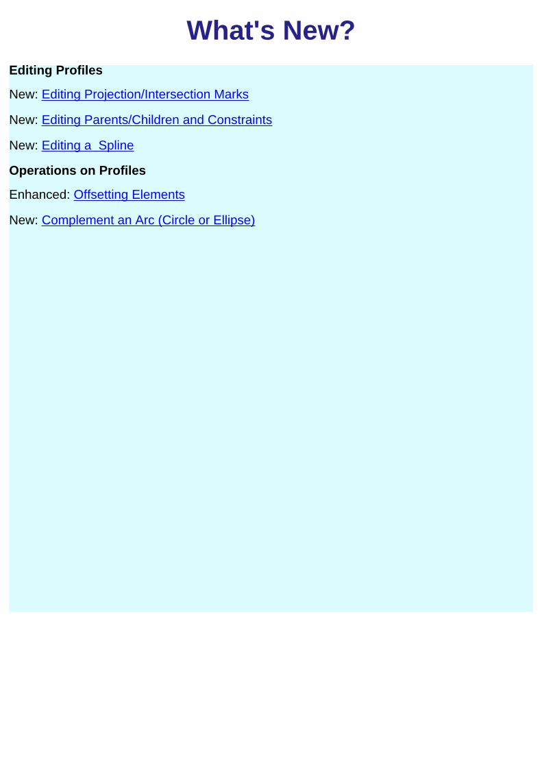
What's New?Editing Profiles
New: Editing Projection/Intersection Marks
New: Editing Parents/Children and Constraints
New: Editing a Spline
Operations on Profiles
Enhanced: Offsetting Elements
New: Complement an Arc (Circle or Ellipse)

Command (and Option) BoardGeneral
Start a Sketch Snap to Point
Leave Sketcher Workbench Standard or Construction Elements
Ctrl Lock currently detected constraintsShift Deactivate a constraint
Geometrical constraint
Dimensional Constraints
Sketched Geometry
Profile
Line
Tangent Arc
Three Point Arc
Predefined Profiles
Oriented Rectangle Cylindrical Elongated Hole
Elongated Hole Keyhole
Hexagon
Circle
Basic Circle Basic Arc
Three Point Circle Arc Three Points
Tri-Tangent Circle Arc Three Point via Limits
Line
Bi-Tangent Line Infinite Line
Bisecting Line Elements

Spline
Connecting Elements
Axis
Conic Point
Ellipse Point (Ctrl P)
Parabola by Focus Point Using Coordinates
Hyperbola by Focus Equidistant Point
Conic Intersection Point
Projection Point
Operations on Sketched Geometry
Corners Trim Both Elem. Trim One No Trim
Chamfers (Ctrl h) Trim Both Elem. Trim One
Trim Elem. Trim Both Elem. Trim One Close Elem. Quick Trim
Break Elements (Ctrl B)
Transformation
Symmetrical Elements (Ctrl S) Scale Elements
Translate Elements Offset Elements
Rotate Elements
3D Geometry
Project 3D Elements Intersect 3D Elements with Sketch Plane

Constraints
Constraints (Dialog Box) (Ctrl o) Autoconstraining
Contact Constraints Animate Constraint
Dimensional/Geometrical (Ctrl C)
Element Colors
Element Color Element Color
Current white Fixed green
Selected red orange Iso-constrained green
Protected yellow Over-constrained violet
No changed brown Inconsistent red
Constraint Visualization
Symbol Type Symbol Type
Perpendicular
Parallel
Coincident symdistrad01.gif(242bytes)
RadiusDistanceLength
symbvert01.gif(106bytes)
Vertical symdistrad02.gif(915bytes)
Diameter
symbhor01.gif(132bytes)
Horizontal Concentric
symbfix01.gif(136bytes)
Fix customize all types

Getting StartedThe Sketcher workbench provides a set of functionalities for creating and modifying sketched elements. Note that you canapply constraints to the sketched elements.
Specification to be used
Final Pad
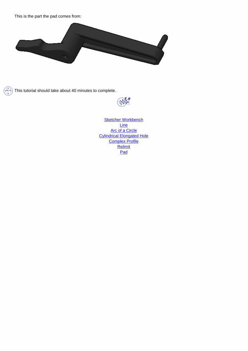
This is the part the pad comes from:
This tutorial should take about 40 minutes to complete.
Sketcher Workbench
LineArc of a Circle
Cylindrical Elongated HoleComplex Profile
RelimitPad
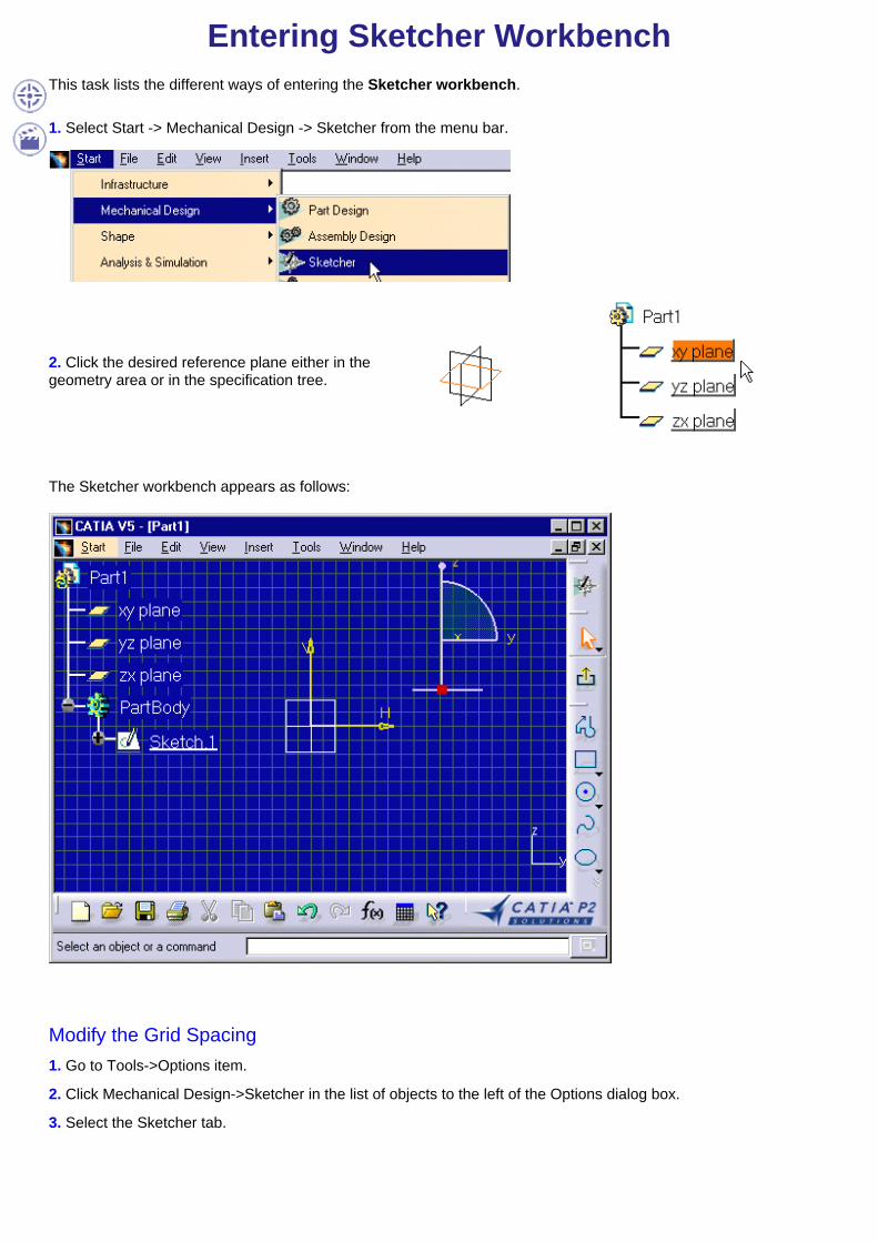
Entering Sketcher WorkbenchThis task lists the different ways of entering the Sketcher workbench.
1. Select Start -> Mechanical Design -> Sketcher from the menu bar.
2. Click the desired reference plane either in thegeometry area or in the specification tree.
The Sketcher workbench appears as follows:
Modify the Grid Spacing1. Go to Tools->Options item.
2. Click Mechanical Design->Sketcher in the list of objects to the left of the Options dialog box.
3. Select the Sketcher tab.

4. Enter 10mm as Primary spacing.
5. If needed, deactivated the Snap to point mode.
Click here to have more information on Grid options.
6. Click OK in the dialog box.
You can now start working in the Sketcher workbench.

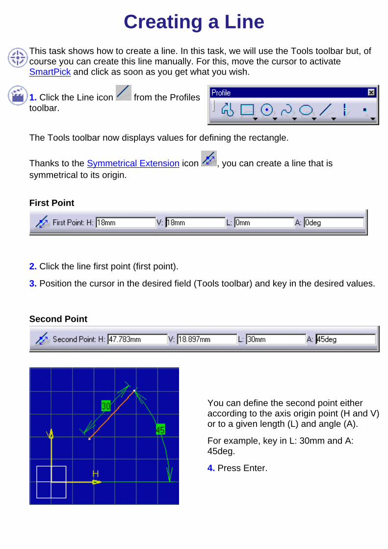
Creating a LineThis task will show you how to create a line in order to define point C (line left extremity).
The Tools toolbar appears.
As you will see all along this tutorial, the Tools toolbar displays not only commandoptions but also given fields and values that appear in accordance with thecommand you select. This toolbar is situated at the bottom right of the softwarescreen.If you cannot see it properly, just undock it.
Snap to Point
Standard or Construction Elements
Geometrical Constraints (this icon is active, by default).
Dimensional Constraints (this icon is active, by default).
1. Activate the Construction Element icon from the Tools toolbar.Construction lines are lines that are internal to, and only visualized by, the sketch. Theselines are used as positioning reference. They are not used to create solid primitives.
2. Click the Line icon .When the cursor goes over the axis origin, a bluesymbol appears (coincidence between the axisorigin point and the line start point).
3. Keep the coincidence symbol active and click theaxis origin point.You created the first extremity point of the line.

The Tools toolbar now displays the following fields and values:
The values that appear in the toolbar (H, V, L, A and so forth) are automaticallyupdated as you move the cursor.The Tools toolbar constantly provides the characteristics of the current element(First Point, as an example) as well as the position of this element.In addition to the toolbar and whenever possible, the element is dynamicallydisplayed as it is created. As a result, you can choose more efficiently the optimumconfiguration for this element.
4. Press the TAB key as many times as necessary to position the cursor in the desiredfield of the Tools toolbar. You can use the cursor to select the desired field.In this particular case, position the cursor in L field (length) and key in L: 20.The value you just keyed in automatically appears in the Tools toolbar, as well as thecorresponding unit.
5. Position the cursor in A field (angle) and key in 188.
The values of the line second extremity point directly appear in the Tools toolbar (L andA).
6. Press Enter.The angle value you keyed in is oriented. As aconsequence, keying in -172 amounts to keying +188degrees. The constraint is represented by a 172 anglevalue because constraint representation system doesnot manage angle symbols.

In fact, symbol representation is issued out by means of angle sector management thatyou can modify by double clicking angle constraint representation.
Note that if the constraint representation overlays some of the geometry, you can movethis constraint representation by dragging it with the cursor.
The line is created. Constraints (Length: 20mm and Angle: 188 degrees) appear on theline.
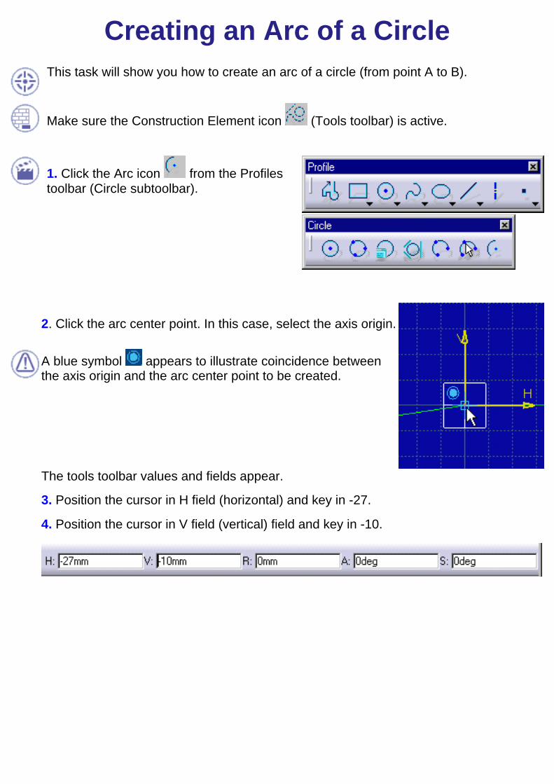
Creating an Arc of a CircleThis task will show you how to create an arc of a circle (from point A to B).
Make sure the Construction Element icon (Tools toolbar) is active.
1. Click the Arc icon from the Profilestoolbar (Circle subtoolbar).
2. Click the arc center point. In this case, select the axis origin.
A blue symbol appears to illustrate coincidence betweenthe axis origin and the arc center point to be created.
The tools toolbar values and fields appear.
3. Position the cursor in H field (horizontal) and key in -27.
4. Position the cursor in V field (vertical) field and key in -10.
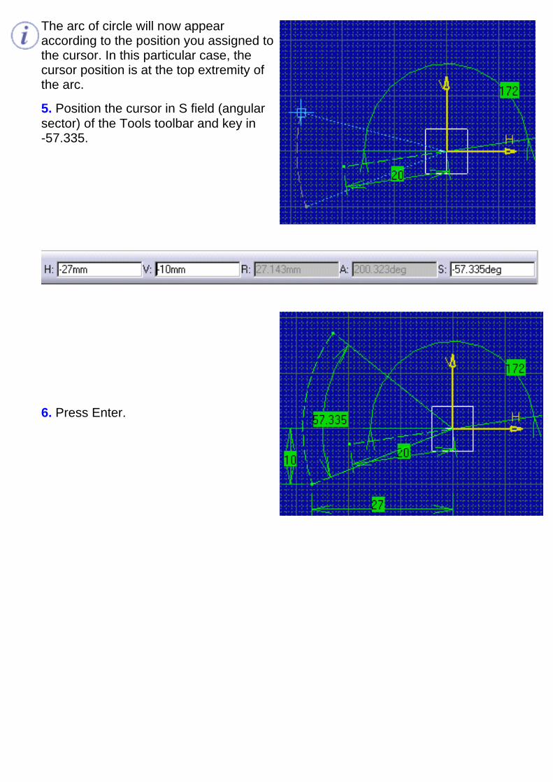
The arc of circle will now appearaccording to the position you assigned tothe cursor. In this particular case, thecursor position is at the top extremity ofthe arc.
5. Position the cursor in S field (angularsector) of the Tools toolbar and key in-57.335.
6. Press Enter.
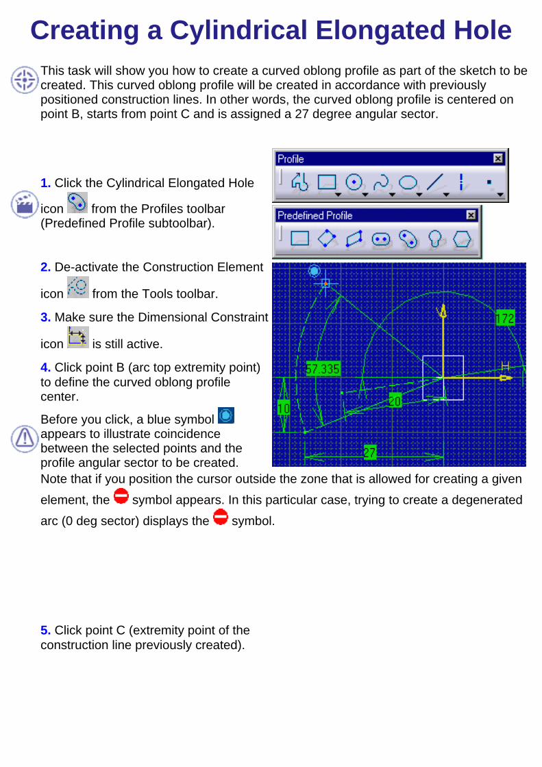
Creating a Cylindrical Elongated HoleThis task will show you how to create a curved oblong profile as part of the sketch to becreated. This curved oblong profile will be created in accordance with previouslypositioned construction lines. In other words, the curved oblong profile is centered onpoint B, starts from point C and is assigned a 27 degree angular sector.
1. Click the Cylindrical Elongated Hole
icon from the Profiles toolbar(Predefined Profile subtoolbar).
2. De-activate the Construction Element
icon from the Tools toolbar.
3. Make sure the Dimensional Constraint
icon is still active.
4. Click point B (arc top extremity point)to define the curved oblong profilecenter.
Before you click, a blue symbol appears to illustrate coincidencebetween the selected points and theprofile angular sector to be created.
Note that if you position the cursor outside the zone that is allowed for creating a givenelement, the symbol appears. In this particular case, trying to create a degeneratedarc (0 deg sector) displays the symbol.
5. Click point C (extremity point of theconstruction line previously created).
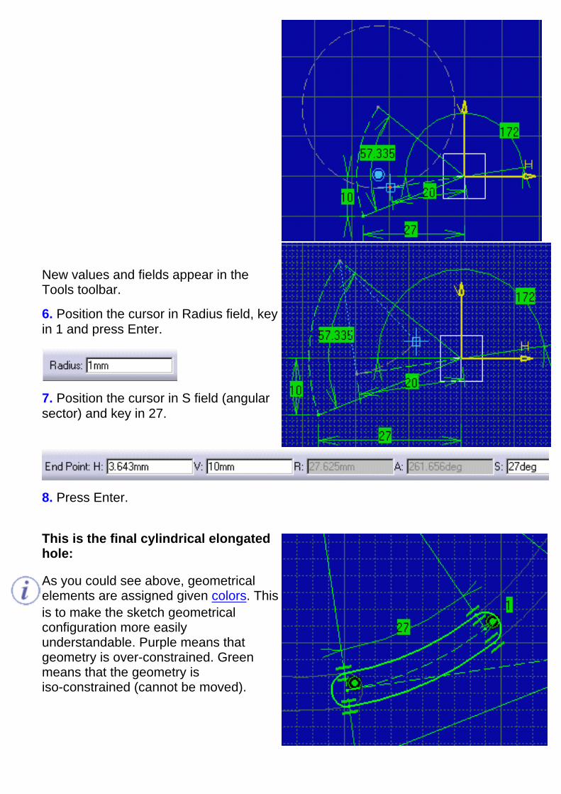
New values and fields appear in theTools toolbar.
6. Position the cursor in Radius field, keyin 1 and press Enter.
7. Position the cursor in S field (angularsector) and key in 27.
8. Press Enter.
This is the final cylindrical elongatedhole:
As you could see above, geometricalelements are assigned given colors. Thisis to make the sketch geometricalconfiguration more easilyunderstandable. Purple means thatgeometry is over-constrained. Greenmeans that the geometry isiso-constrained (cannot be moved).

At this step, we strongly advise that you save the cylindrical elongated hole.

Creating a Complex ProfileThis task shows how to create a more complex profile which is another part of the finalsketch. You are going to create lines and arcs of circles one after the other.
In case you did not save the previously created sketch, you can open theGettingStarted_profile01.CATPart document.
If you are not satisfied with what you create, you can, at any time, use Undo or
Redo icons.
Specification:

1. Click on the Profile icon from the Profiles toolbar.
The Tools toolbar now displays the following option commands and values:
Line Tangent Arc Three Point Arc
Three Point Arc
2. Select the Three Point Arc option command from the Tools toolbar.3. Select a point on the curved oblong profile (arc D).
Coincidence ( ) is applied between arc D on the cylindrical elongated hole and thearc start point.
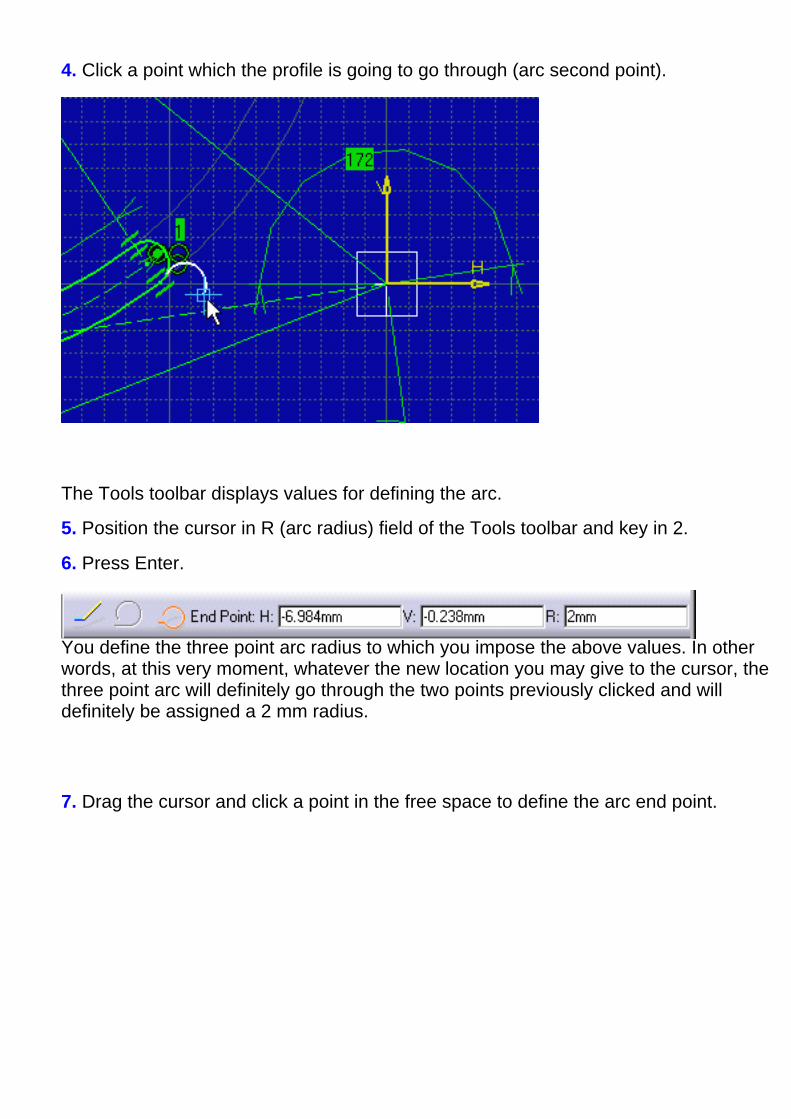
4. Click a point which the profile is going to go through (arc second point).
The Tools toolbar displays values for defining the arc.
5. Position the cursor in R (arc radius) field of the Tools toolbar and key in 2.
6. Press Enter.
You define the three point arc radius to which you impose the above values. In otherwords, at this very moment, whatever the new location you may give to the cursor, thethree point arc will definitely go through the two points previously clicked and willdefinitely be assigned a 2 mm radius.
7. Drag the cursor and click a point in the free space to define the arc end point.

Tangent Line
Make sure the Line option command (Tools toolbar) is now active.
8. Start dragging the line in order to make it tangent to the arc you just created.
To make this line tangent to the arc you just created, SmartPick automatically helpsfixing the cursor position so that tangency may be kept. Autodetection displays the
tangency symbol .
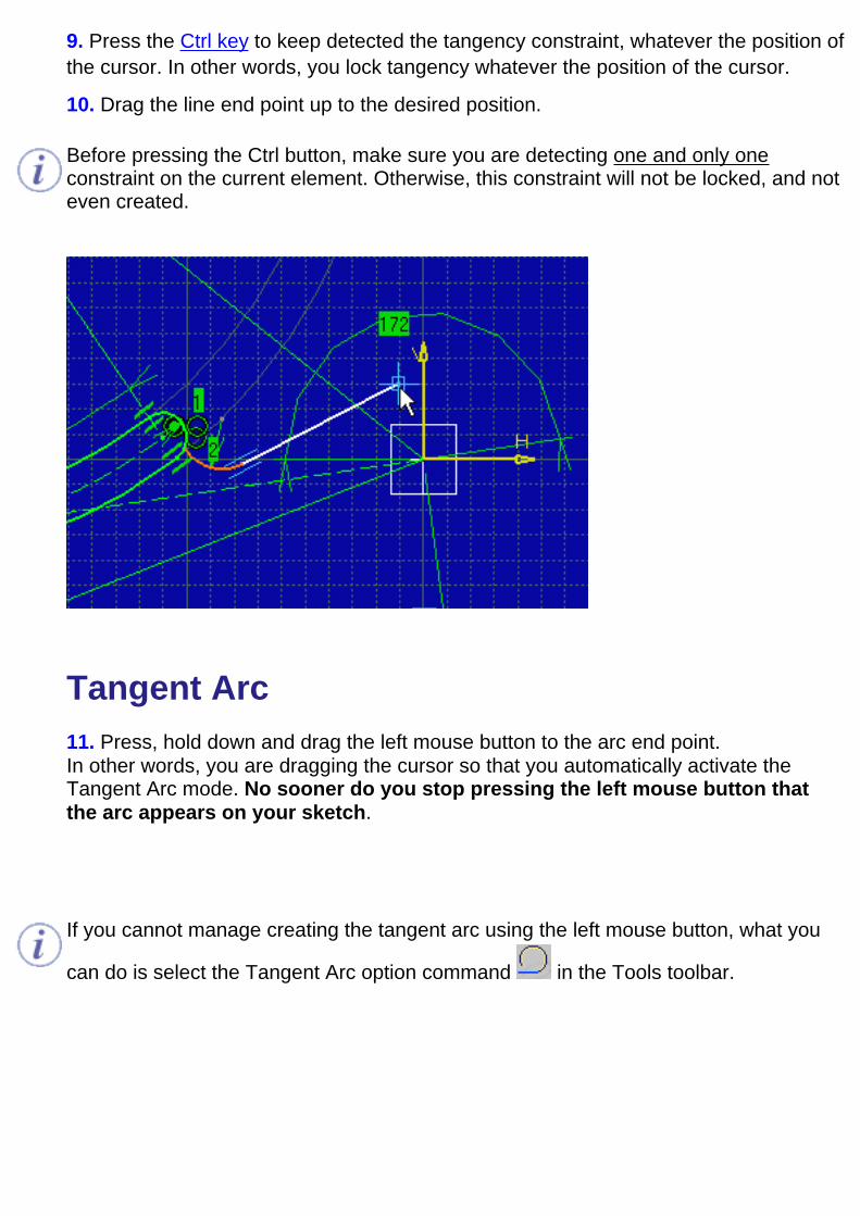
9. Press the Ctrl key to keep detected the tangency constraint, whatever the position ofthe cursor. In other words, you lock tangency whatever the position of the cursor.
10. Drag the line end point up to the desired position.
Before pressing the Ctrl button, make sure you are detecting one and only oneconstraint on the current element. Otherwise, this constraint will not be locked, and noteven created.
Tangent Arc 11. Press, hold down and drag the left mouse button to the arc end point.In other words, you are dragging the cursor so that you automatically activate theTangent Arc mode. No sooner do you stop pressing the left mouse button thatthe arc appears on your sketch.
If you cannot manage creating the tangent arc using the left mouse button, what you
can do is select the Tangent Arc option command in the Tools toolbar.
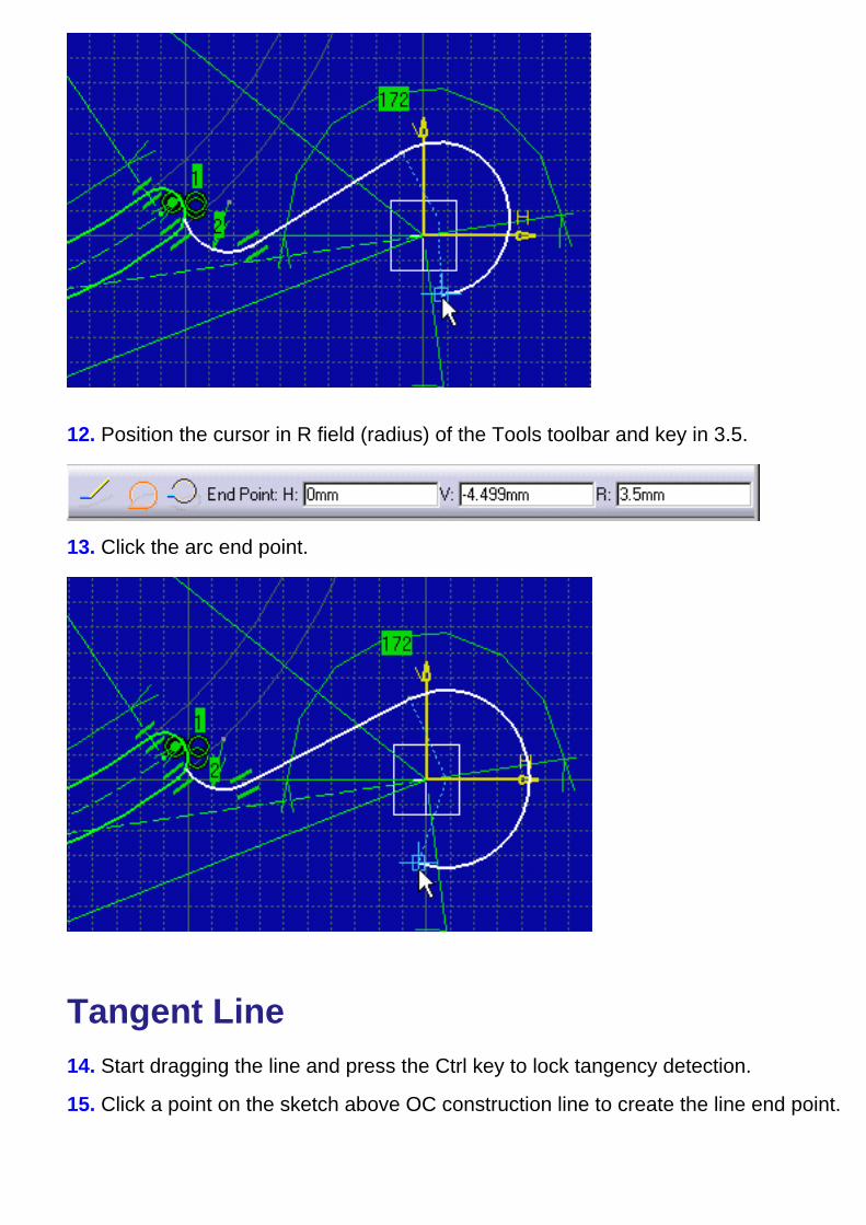
12. Position the cursor in R field (radius) of the Tools toolbar and key in 3.5.
13. Click the arc end point.
Tangent Line 14. Start dragging the line and press the Ctrl key to lock tangency detection.
15. Click a point on the sketch above OC construction line to create the line end point.
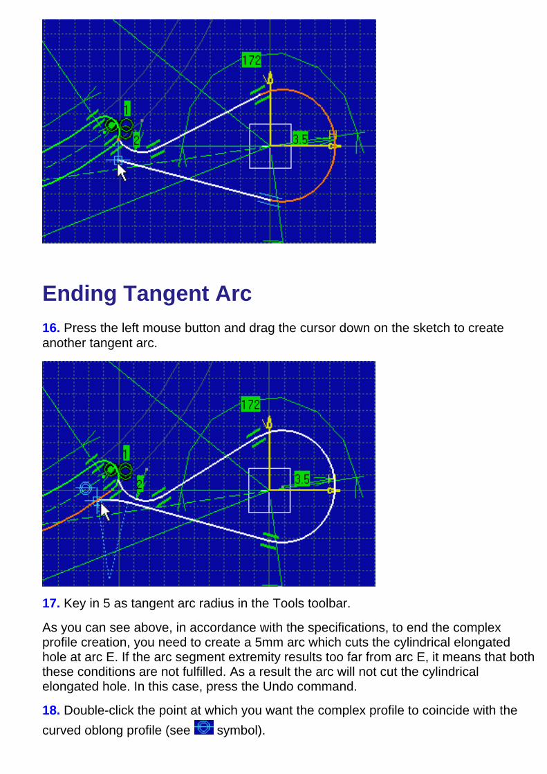
Ending Tangent Arc16. Press the left mouse button and drag the cursor down on the sketch to createanother tangent arc.
17. Key in 5 as tangent arc radius in the Tools toolbar.
As you can see above, in accordance with the specifications, to end the complexprofile creation, you need to create a 5mm arc which cuts the cylindrical elongatedhole at arc E. If the arc segment extremity results too far from arc E, it means that boththese conditions are not fulfilled. As a result the arc will not cut the cylindricalelongated hole. In this case, press the Undo command.
18. Double-click the point at which you want the complex profile to coincide with thecurved oblong profile (see symbol).
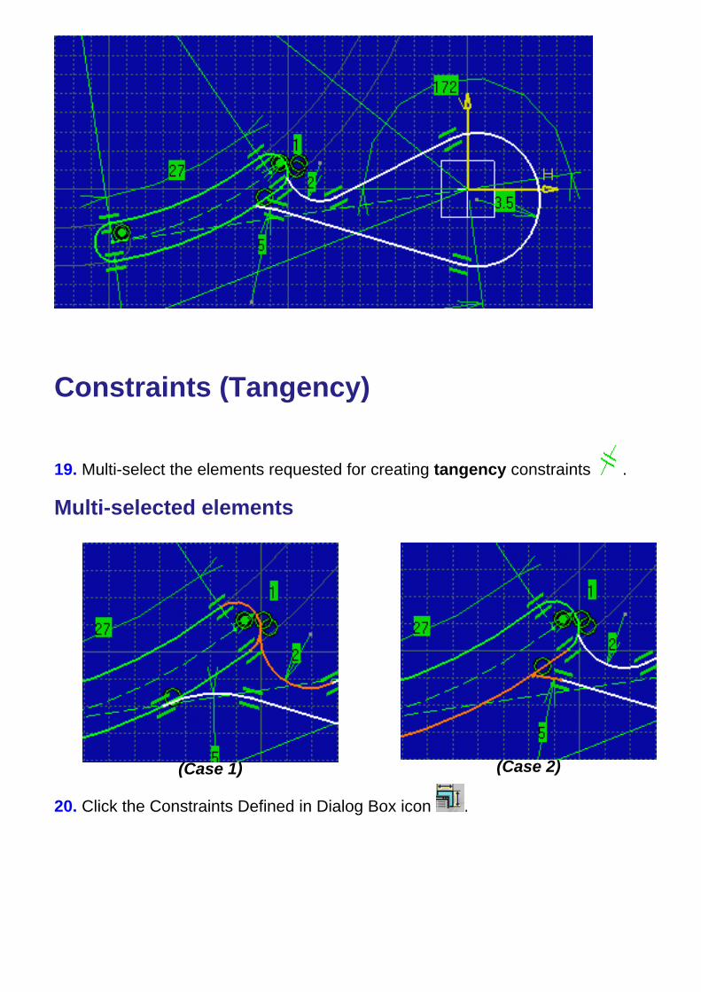
Constraints (Tangency)
19. Multi-select the elements requested for creating tangency constraints .
Multi-selected elements
(Case 1) (Case 2)
20. Click the Constraints Defined in Dialog Box icon .

21. Check the desired options in theConstraint Definition dialog box.
Resulting tangency constraints
(Case 1) (Case 2)
Constraints (Coincidence)
22. Multi-select the arc center point andthe axis origin point for creating a
coincidence constraint .
Multi-selected elements
23. Click the Constraints Defined in Dialog
Box icon and check the desiredoptions in the Constraint Definition dialogbox.
Resulting constraint

Final Complex Profile:
Final Specification Tree:
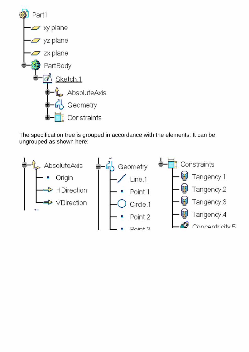
The specification tree is grouped in accordance with the elements. It can beungrouped as shown here:

Relimiting the ProfileThis task shows how to relimit the profile you just created by trimming some elementsin this profile.
1. Double-click the Quick Trim icon from the Operation subtoolbar(Relimitations subtoolbar).
The possible trim option command aredisplayed in the Tools toolbar.
2. Click the Rubber In option command inthe Tools toolbar.
3. Select the elements to be trimmed, one after the other.
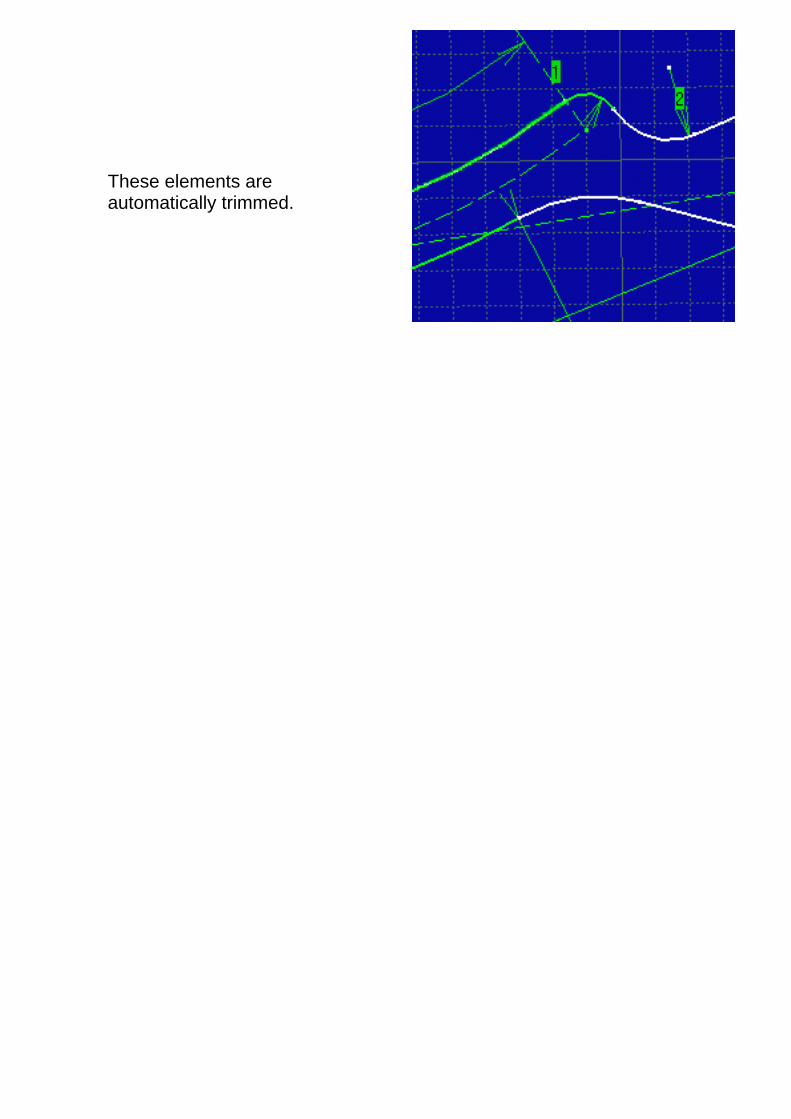
These elements areautomatically trimmed.

Generating a PadThis task shows you how to create a pad from the profile previously created. For this,you will leave the Sketcher workbench and automatically enter Part Design workbench.
1. Click the Exit icon .You are now in Part Design workbench. If this is not the case, select Start ->Mechanical Design -> Part Design from the menu bar.
The sketched profile appears as follows:
2. Click the Pad icon .The Pad Definition dialog boxappears.
3. Enter 5mm as the pad Length.
4. Click OK.

The pad appears as shown here:

Basic TasksThe Sketcher workbench provides a simple method for creating and editing 2D geometry as well as creating relations betweengeometrical elements. Once created, you can set constraints between geometrical elements, if you need more complex sketches.
Command BoardBefore you Begin
Entering Sketcher WorkbenchSmartPick
Simple ProfilesPre-Defined Profiles
Editing ProfilesOperations on Profiles
Constraints

Tools
See Snap to Point See Creating Standard or Construction Elements
See Setting Constraints See Setting Constraints
See Creating Corners See Trimming Elements With Both Elements Trimmed
See Creating Corners (One Element Trimmed) See Trimming Elements With One Element Trimmed
See Creating Corners (No Element Trimmed) See Trimming Multiple Elements
See Creating Chamfers with Both Elements Trimmed See Closing Elements
See Creating Chamfers with One Element Trimmed See Breaking and Trimming Elements
See Creating Chamfers with No Element Trimmed
See Creating Symmetrical Elements
Before You BeginBefore you begin, you should be familiar with the following tools and concepts that will helpyou in:
creating simple or predefined profile with or without using SmartPickingediting or performing operations on these profilesadding constraints on profiles
Using Tools
Use the Tools toolbar displayed in the bottom right part of the softwarescreen which provides helpful options
Using ColorsUse colors to define either graphical properties or constraint diagnostics.
Cutting the Part by the Sketch PlaneHide the portion of part you do not want to see in the Sketcher.
Converting Standard into Construction ElementsAssign a new type of a line to an element for differentiating constructionfrom non construction elements.

Using SmartPickSmartPick allows you working with a higher productivity by using the available SmartPick cursor.
Before you Begin
You should be familiar with important concepts.SmartPicking a Point
Specify a location either for you to create geometry or for SmartPick toreturn information via symbols.
Creating Geometry Using SmartPickPosition geometry to be created according to existing geometry, if needed,and to internal parameters.

Using Tools For SketchingThis task shows how the software can assist you when sketching elements.
The Tools toolbar is displayed in the bottom right part of the software screen andprovides the following options commands:
Snap to Point
Construction/Standard Element
Geometrical Constraints
Dimensional Constraints
Value fields (Tools toolbar)
You do not necessarily visualize the whole Tools toolbar. Just undock it todisplay all the available options and fields.
Snap to PointIf activated, this option makes your sketch begin or end on the points of the grid. As you aresketching the points are snapped to the intersection points of the grid. Note that this optionis also available in the Tools->Options, Mechanical Design -> Sketcher option at the left ofthe dialog box (Sketcher tab). For more information, see Infrastructure user's guide(Customization Settings).
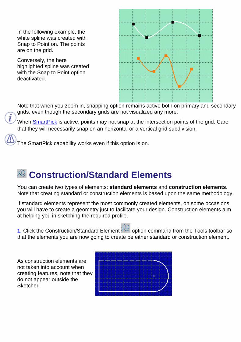
In the following example, thewhite spline was created withSnap to Point on. The pointsare on the grid.
Conversely, the herehighlighted spline was createdwith the Snap to Point optiondeactivated.
Note that when you zoom in, snapping option remains active both on primary and secondarygrids, even though the secondary grids are not visualized any more.
When SmartPick is active, points may not snap at the intersection points of the grid. Carethat they will necessarily snap on an horizontal or a vertical grid subdivision.
The SmartPick capability works even if this option is on.
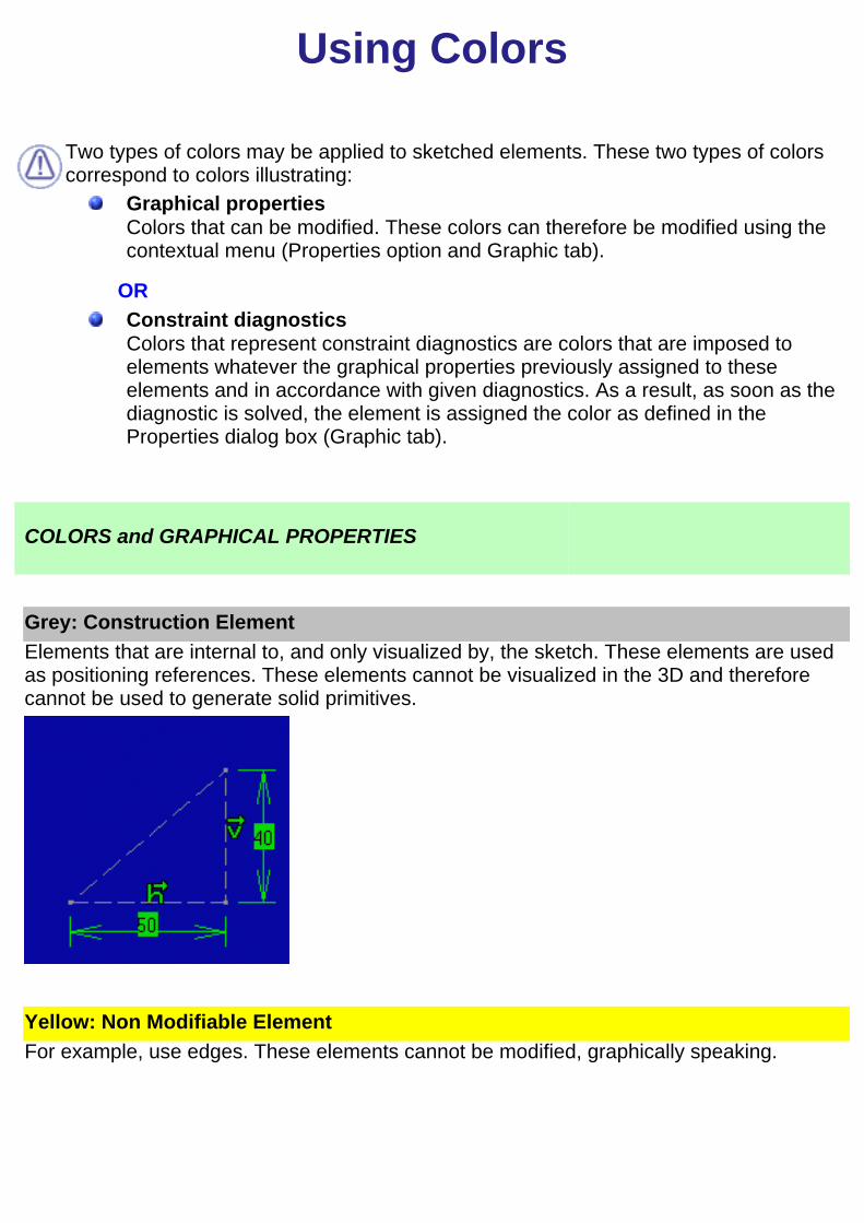
Construction/Standard ElementsYou can create two types of elements: standard elements and construction elements.Note that creating standard or construction elements is based upon the same methodology.
If standard elements represent the most commonly created elements, on some occasions,you will have to create a geometry just to facilitate your design. Construction elements aimat helping you in sketching the required profile.
1. Click the Construction/Standard Element option command from the Tools toolbar sothat the elements you are now going to create be either standard or construction element.
As construction elements arenot taken into account whencreating features, note that theydo not appear outside theSketcher.

Note that in the case of hexagons, construction element type is automatically used forsecondary circles. This type of sketch is interesting in that it simplifies the creation and theways in which it is constrained. Setting a radius constraint on the second circle is enough toconstrain the whole hexagon. Just imagine what you would have to do to constrainhexagons sketched with no construction circles!
Geometrical ConstraintsWhen selected, the Geometrical Constraint option command allows forcing a limitationbetween one or more geometry elements.
Dimensional ConstraintsWhen selected, the Dimensional Constraint option command allows forcing a dimensionallimitation on one or more profile type elements provided you use the value fields in the Toolstoolbar for creating this profile.
To know more about sketcherconstraints, please refer toSetting Constraints, andInfrastructure user's guide(Customization Settings).
Value Fields (Tools Toolbar)

The values of the elements you sketch appear in the Tools toolbar as you move the cursor.In other words, as you are moving the cursor, the Horizontal (H), Vertical (V), Length (L) andAngle (A) fields display the coordinates corresponding to the cursor position.
You can also use these fields for entering the values of your choice. In the followingscenario, you are going to sketch a line by entering values in the appropriate fields.
1. Click the Line icon.
The Tools toolbar displays information in the four value fields.
2. Enter the coordinates of the First Point.
3. Enter the coordinates of the Second Point.
OR
2. Enter the length (L) of the line.
3. Enter the value of the angle (A) between the line to be created and the horizontal axis.
4. Click the first point on the line.
The line is created.Depending on the number of fields available and the way you customize your toolbars, somefields may be truncated. What you need to do is just undock the Tools toolbar.
Using Colors
Two types of colors may be applied to sketched elements. These two types of colorscorrespond to colors illustrating:
Graphical propertiesColors that can be modified. These colors can therefore be modified using thecontextual menu (Properties option and Graphic tab).
ORConstraint diagnosticsColors that represent constraint diagnostics are colors that are imposed toelements whatever the graphical properties previously assigned to theseelements and in accordance with given diagnostics. As a result, as soon as thediagnostic is solved, the element is assigned the color as defined in theProperties dialog box (Graphic tab).
COLORS and GRAPHICAL PROPERTIES
Grey: Construction Element
Elements that are internal to, and only visualized by, the sketch. These elements are usedas positioning references. These elements cannot be visualized in the 3D and thereforecannot be used to generate solid primitives.
Yellow: Non Modifiable Element
For example, use edges. These elements cannot be modified, graphically speaking.
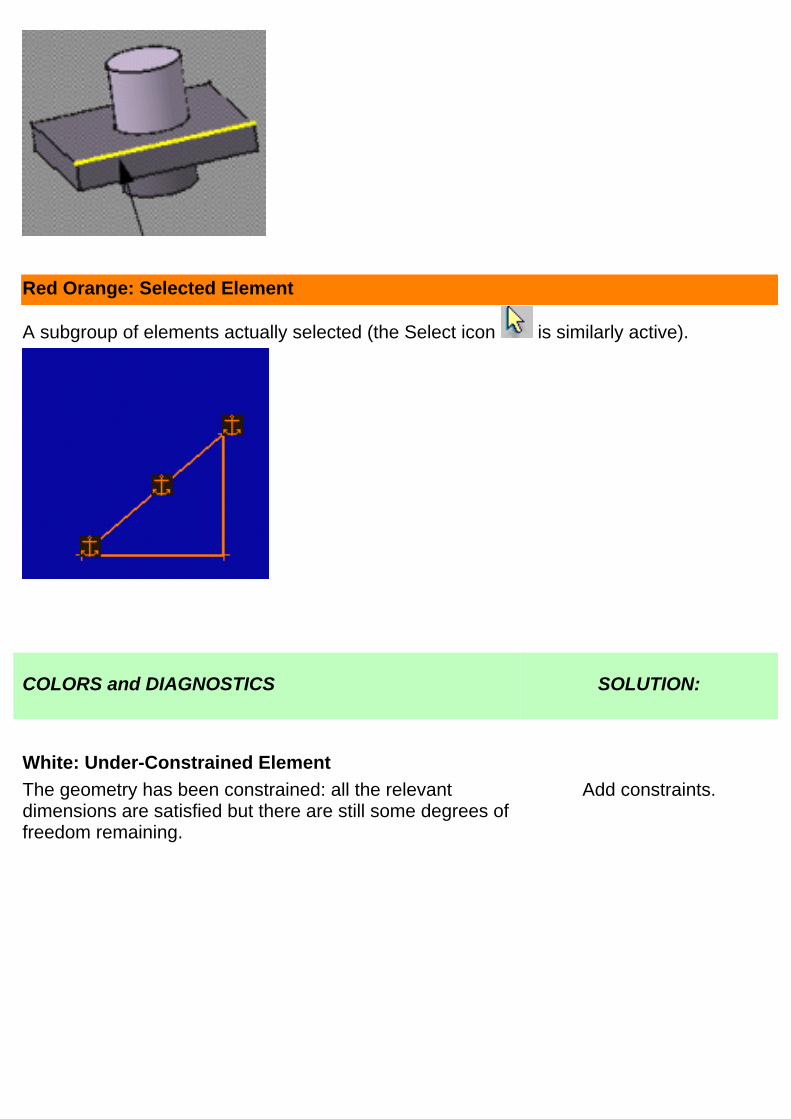
Red Orange: Selected Element
A subgroup of elements actually selected (the Select icon is similarly active).
COLORS and DIAGNOSTICS SOLUTION:
White: Under-Constrained Element
The geometry has been constrained: all the relevantdimensions are satisfied but there are still some degrees offreedom remaining.
Add constraints.
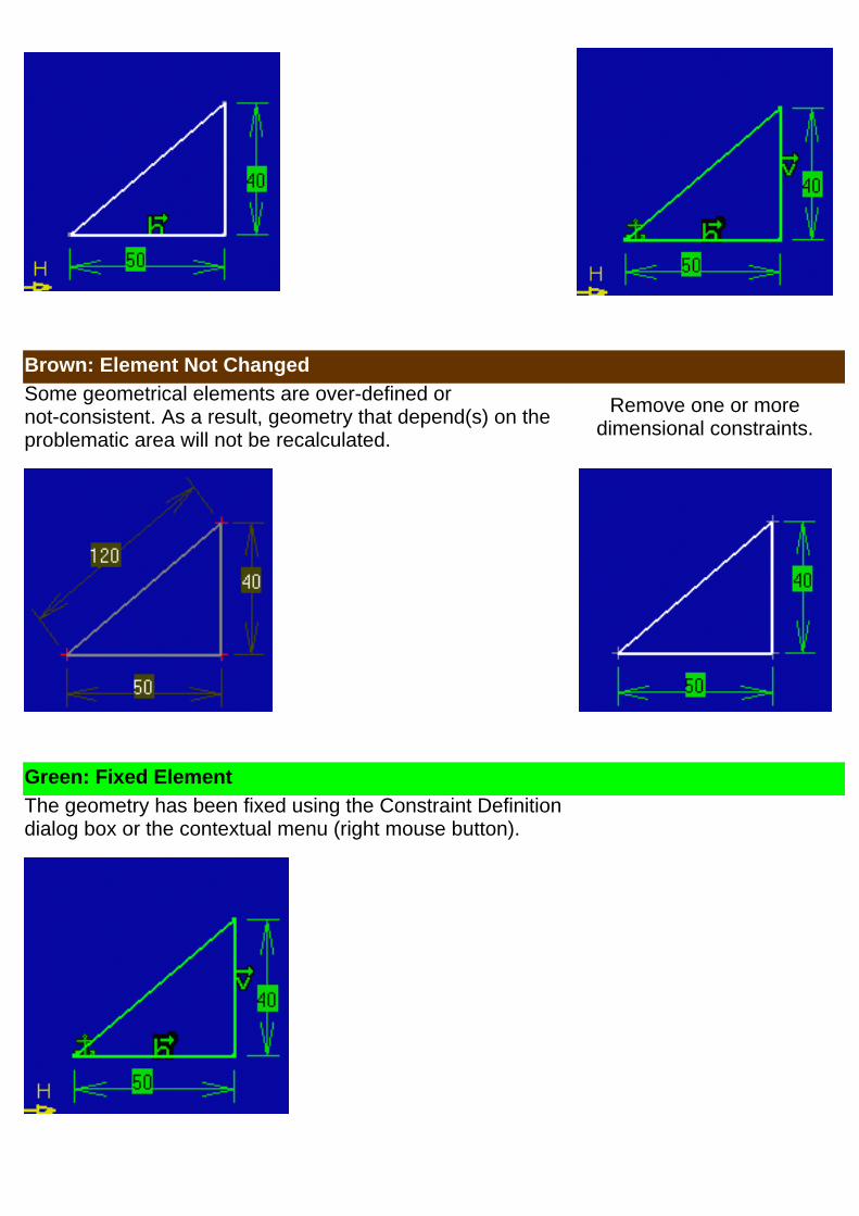
Brown: Element Not Changed
Some geometrical elements are over-defined ornot-consistent. As a result, geometry that depend(s) on theproblematic area will not be recalculated.
Remove one or moredimensional constraints.
Green: Fixed Element
The geometry has been fixed using the Constraint Definitiondialog box or the contextual menu (right mouse button).
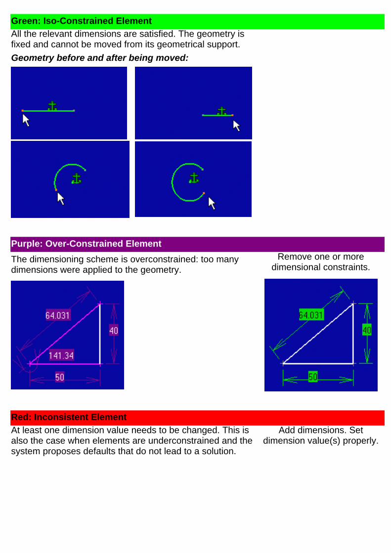
Green: Iso-Constrained Element
All the relevant dimensions are satisfied. The geometry isfixed and cannot be moved from its geometrical support.
Geometry before and after being moved:
Purple: Over-Constrained Element
The dimensioning scheme is overconstrained: too manydimensions were applied to the geometry.
Remove one or moredimensional constraints.
Red: Inconsistent Element
At least one dimension value needs to be changed. This isalso the case when elements are underconstrained and thesystem proposes defaults that do not lead to a solution.
Add dimensions. Setdimension value(s) properly.

Inconsistent and Over-Constrained Elements:
When leaving the sketcher, the software will only generate a warning for inconsistent and over-constrained elements if they belong to asketch issued from the release 5 or releases before. Since release 6, the software generates an error.
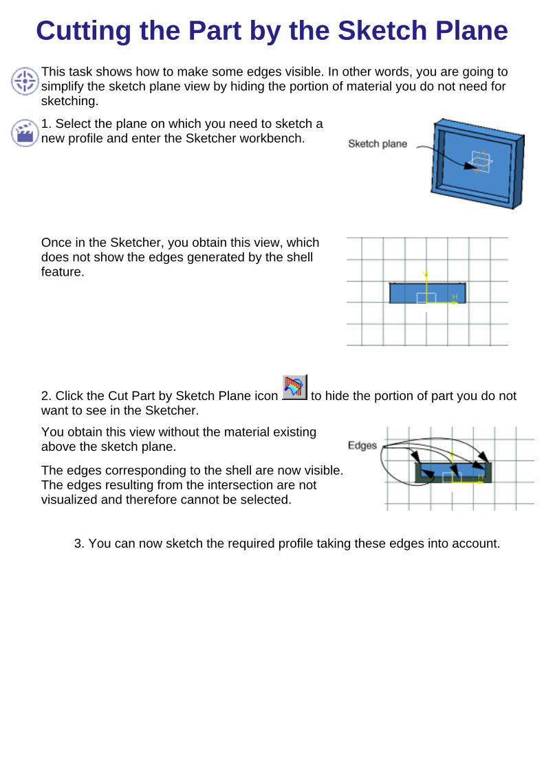
Cutting the Part by the Sketch PlaneThis task shows how to make some edges visible. In other words, you are going tosimplify the sketch plane view by hiding the portion of material you do not need forsketching.
1. Select the plane on which you need to sketch anew profile and enter the Sketcher workbench.
Once in the Sketcher, you obtain this view, whichdoes not show the edges generated by the shellfeature.
2. Click the Cut Part by Sketch Plane icon to hide the portion of part you do notwant to see in the Sketcher.You obtain this view without the material existingabove the sketch plane.
The edges corresponding to the shell are now visible.The edges resulting from the intersection are notvisualized and therefore cannot be selected.
3. You can now sketch the required profile taking these edges into account.

Converting Standard into ConstructionElements
This task shows how to convert standard elements into construction elements andvice versa.Open the Construction_Standard.CATPart document from the\online\samples\Sketcher directory.1. Select the line (standard type) you wish toconvert into a construction line.
2. Click the Construction/Standard Element option
command from the Tools toolbar.
The line you previously selected appears dashed toshow it is a new type of line.
3. Click the Construction/Standard Element option
command again.
The construction line is converted into a standardline.
Double-clicking on the line displays the Line Definition dialog box in which you canun-check the Construction element option if you want to convert the construction lineinto a standard line. For more information, refer to Modifying Element Coordinates.
Construction lines are not taken into account when entering another workbench.
Applying the Construction/Standard Element option on axes has no effect.

Entering Sketcher WorkbenchThis task lists the different ways of entering the Sketcher workbench.
1. Select Start -> Mechanical Design -> Sketcher from the menu bar.
What you can also do is:
Select the Sketcher icon and click the desired reference plane either in thegeometry area or in the specification tree.
Select the Sketcher icon and select one surface (reference plane).
Double-click one sketch element.Multi-select two edges on an opened part (to define h and v - the axis is alignedon these two edges). Select a surface and then select the Sketcher icon .
Select one plane of the local axis. h and v are aligned to the main axes of thisselected plane. Associativity is kept between both the plane and the sketch.
Note that if you select one or two edges, h will be parallel to the projection of the firstedge in the sketch plane.
If the two projected edges appear as two lines that intersect in the sketch plane, theorigin of the sketch axis will correspond to the two lines intersection point. Note thatthis origin point is a construction point used as a positioning assistant and it cannot bemodified. The Sketcher workbench appears as follows:

Add a Grid1. Go to Tools->Options item.2. Click Mechanical Design-> in the list of objects to the left of the Options dialog box.3. Select the Sketcher tab.
4. Enter 10mm as Primary spacing.5. If needed, deactivated the Snap to point mode.
Click here to have more information on Grid options.
6. Click OK in the dialog box.You can now start working in the Sketcher workbench.
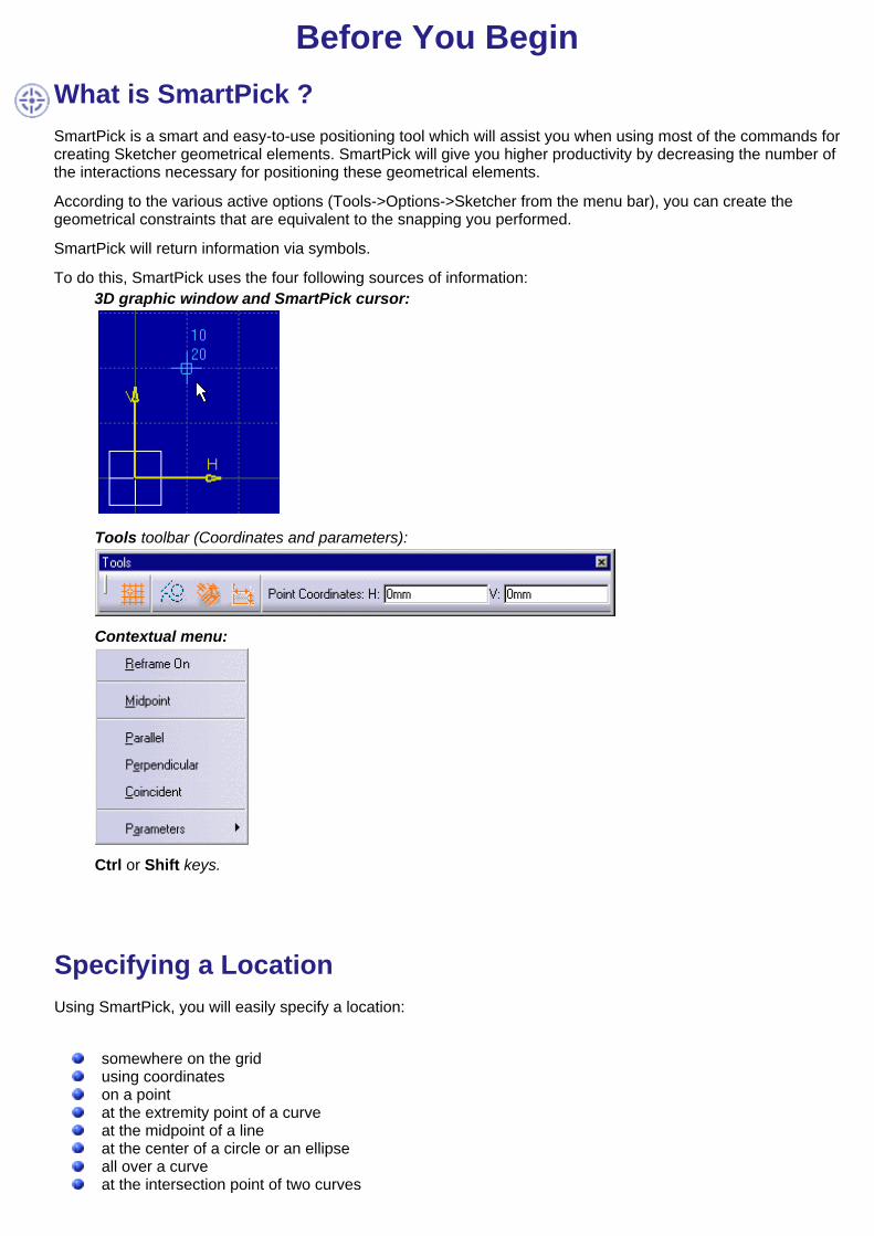
Before You BeginWhat is SmartPick ?SmartPick is a smart and easy-to-use positioning tool which will assist you when using most of the commands forcreating Sketcher geometrical elements. SmartPick will give you higher productivity by decreasing the number ofthe interactions necessary for positioning these geometrical elements.
According to the various active options (Tools->Options->Sketcher from the menu bar), you can create thegeometrical constraints that are equivalent to the snapping you performed.
SmartPick will return information via symbols.
To do this, SmartPick uses the four following sources of information:3D graphic window and SmartPick cursor:
Tools toolbar (Coordinates and parameters):
Contextual menu:
Ctrl or Shift keys.
Specifying a LocationUsing SmartPick, you will easily specify a location:
somewhere on the gridusing coordinateson a pointat the extremity point of a curveat the midpoint of a lineat the center of a circle or an ellipseall over a curveat the intersection point of two curves

aligned at a vertical/horizontal positionon the fictitious perpendicular line through a line end pointany of the above cases possibly combined together, whenever possible.
You will progessively specify this location by providing information using as above mentioned the blue cursor,coordinates, the contextual menu and Shift/Ctrl keys. Of course, as you will specify your needs, you will shorten thescope of the available possibilities for eventually locating the elements as desired.
Note that if you position the cursor outside the zone that is allowed for creating a given element, the symbol appears.
SmartPicking...This task shows you how to specify the location of given geometry thanks to information that SmartPick returnsvia symbols. In other words, SmartPick returns feedback information (highlighted geometry or symbols) which you will or willnot validate.
You will also learn how to progressively specify your needs using the blue cursor, the Tools toolbar, thecontextual menu, Shift key or Ctrl key.
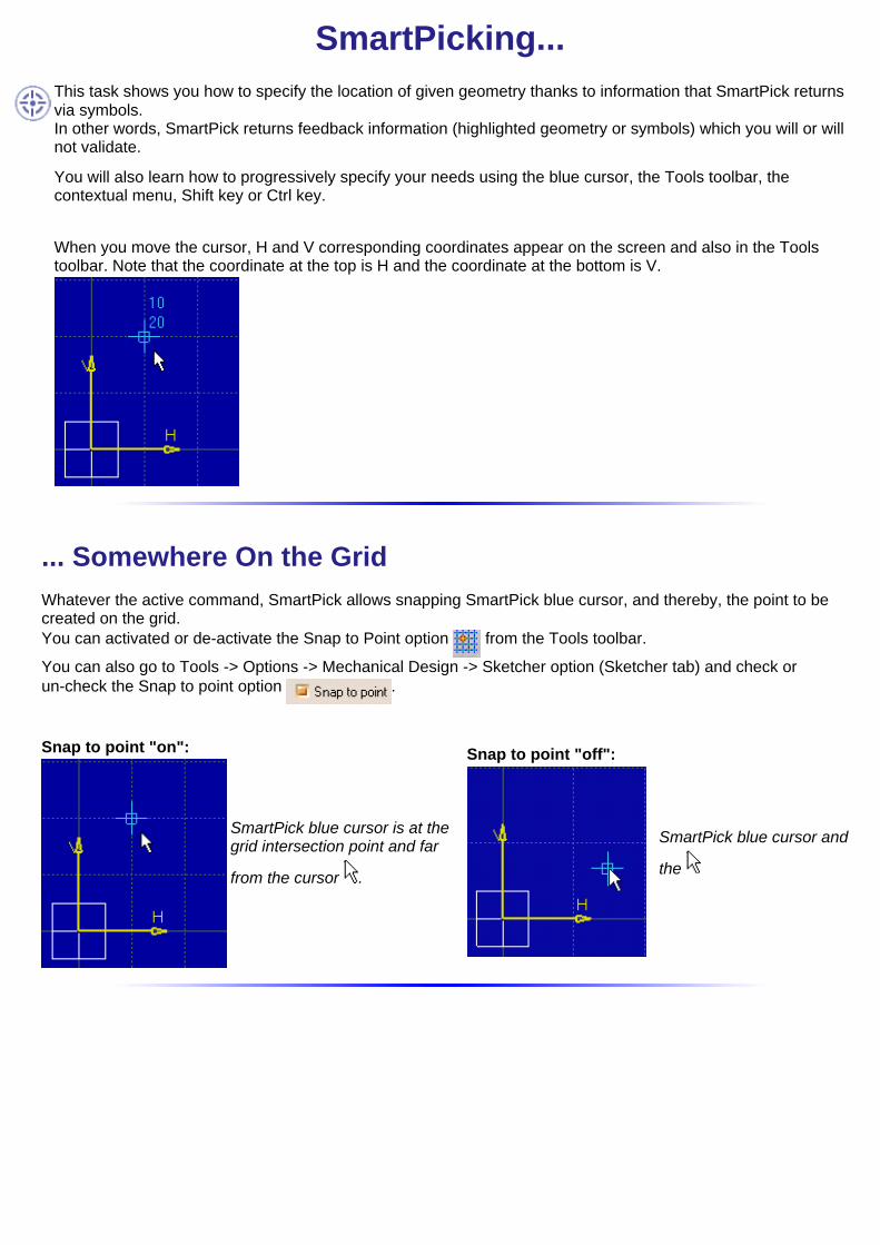
When you move the cursor, H and V corresponding coordinates appear on the screen and also in the Toolstoolbar. Note that the coordinate at the top is H and the coordinate at the bottom is V.
... Somewhere On the GridWhatever the active command, SmartPick allows snapping SmartPick blue cursor, and thereby, the point to becreated on the grid.You can activated or de-activate the Snap to Point option from the Tools toolbar.
You can also go to Tools -> Options -> Mechanical Design -> Sketcher option (Sketcher tab) and check orun-check the Snap to point option .
Snap to point "on":
SmartPick blue cursor is at thegrid intersection point and far
from the cursor .
Snap to point "off":
SmartPick blue cursor and
the

... Using Coordinates
As you move the and try to assign the desired position to the SmartPick cursor, the Tools toolbar similarlydisplays the corresponding horizontal and vertical coordinates of SmartPick blue cursor .
You can use the Tools toolbar fields for defining the point coordinates eitherindependently from each others or not.
For example, enter H: 2mm.
SmartPick is locked on this value. As you move the cursor the V coordinate appearsin the Tools toolbar.
If you want to reset H or V coordinates you just entered in the Tools toolbar, displaythe contextual menu (right-click on the background) and select the Reset option.
... On H and V Axes
As you move the and try to assign the desired position to the SmartPick cursor, ahorizontal fictitious blue dotted line appears when h is equal to zero, a vertical fictitiousblue dotted line appears when v is equal to zero.

... On a PointWhen a point is included in the tolerance zone of SmartPick cursor, SmartPick first snaps to the point and thepoint-to-point coincidence symbol appears . This symbol means that snapping suppresses both degrees offreedom available for a point.
... At a Curve Extremity PointWhen a fictitious curve extremity point is included in the tolerance zone ofsmartPick cursor, SmartPick snaps to the extremity of this curve.
The point-to-point coincidence symbol appears once the point is picked.
Be careful: by default, all the curves are assigned fictitious extremity points. This is why, and as you will probablyexpect, SmartPick detects first point-to-point coincidence with the curve existing end point. Care that in this caseonly the extremity point is highlihted whereas in the previous case the whole line is highligthed.
You can also use the contextual menu (Nearest End Point option) while goingover any curve type element with the cursor, and detect first point-to-pointcoincidence with the curve existing end point.
... At the Midpoint of a Line

When the midpoint of a line is included in the tolerance zone ofSmartPick cursor, SmartPick snaps to the midpoint of this line. Thepoint-to-point coincidence symbol appears once the midpoint ispicked and the line highlights.
For this, you can also use the contextual menu (Midpoint option).
... At the Center of a Circle
When the fictitious center of a circle is included in the tolerance zoneof SmartPick cursor, SmartPick snaps at the center of this circle. Thepoint-to-point coincidence symbol appears once the circle center ispicked and the circle highlights. For this, you can also use thecontextual menu (Concentric option).
Be careful: by default, circles are created with a center point, as defined in Tools -> Options -> MechanicalDesign -> Sketcher option (Sketcher tab). As a result, SmartPick detects first point-to-point coincidence.
... All Over a CurveWhen a curve is included in the tolerance zone of SmartPick cursor, SmartPick automatically snaps to the curve
which highlights. The curve coincidence symbol appears as you go all over the curve with the cursor . Thissymbol means the point is snapped and that there is still one degree of freedom left, except when two curves aredetected at the same time.
This is also true In the case of curves that can be extrapolated, (segments, arcs of circles, re-limited splines orconic curves). SmartPick will snap to these curves on the condition they are included in the tolerance zone ofSmartPick cursor.
Make sure you checked the Support lines and circles option in the Options dialog box. For this, go to Tools ->
Options -> Mechanical Design -> Sketcher option (Sketcher tab).
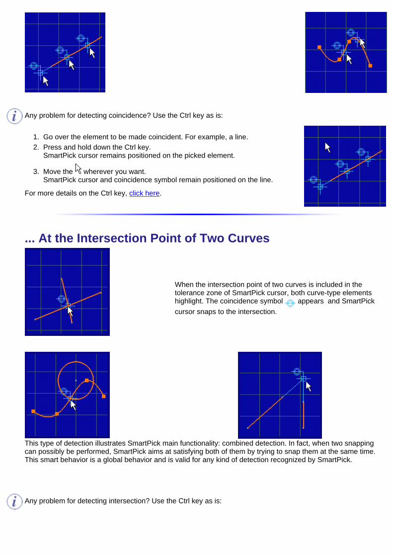
Any problem for detecting coincidence? Use the Ctrl key as is:
Go over the element to be made coincident. For example, a line.1. Press and hold down the Ctrl key.SmartPick cursor remains positioned on the picked element.
2.
Move the wherever you want.SmartPick cursor and coincidence symbol remain positioned on the line.
3.
For more details on the Ctrl key, click here.
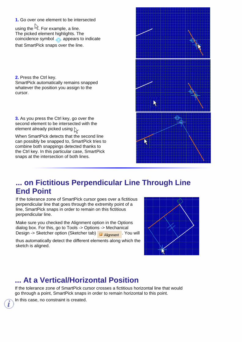
... At the Intersection Point of Two Curves
When the intersection point of two curves is included in thetolerance zone of SmartPick cursor, both curve-type elementshighlight. The coincidence symbol appears and SmartPickcursor snaps to the intersection.
This type of detection illustrates SmartPick main functionality: combined detection. In fact, when two snappingcan possibly be performed, SmartPick aims at satisfying both of them by trying to snap them at the same time.This smart behavior is a global behavior and is valid for any kind of detection recognized by SmartPick.
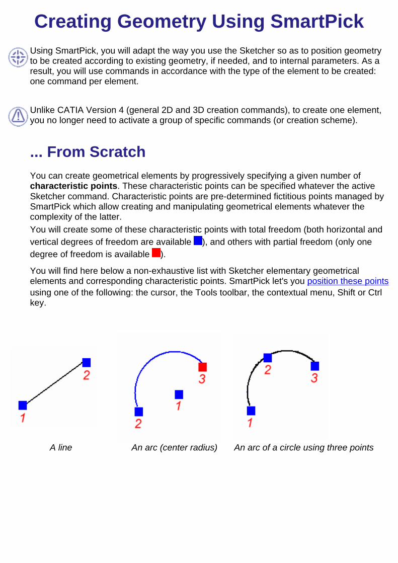
Any problem for detecting intersection? Use the Ctrl key as is:
1. Go over one element to be intersected
using the . For example, a line.The picked element highlights. Thecoincidence symbol appears to indicatethat SmartPick snaps over the line.
2. Press the Ctrl key.SmartPick automatically remains snappedwhatever the position you assign to thecursor.
3. As you press the Ctrl key, go over thesecond element to be intersected with theelement already picked using .When SmartPick detects that the second linecan possibly be snapped to, SmartPick tries tocombine both snappings detected thanks tothe Ctrl key. In this particular case, SmartPicksnaps at the intersection of both lines.
... on Fictitious Perpendicular Line Through Line
End Point
If the tolerance zone of SmartPick cursor goes over a fictitiousperpendicular line that goes through the extremity point of aline, SmartPick snaps in order to remain on this fictitiousperpendicular line.
Make sure you checked the Alignment option in the Optionsdialog box. For this, go to Tools -> Options -> MechanicalDesign -> Sketcher option (Sketcher tab) . You will
thus automatically detect the different elements along which thesketch is aligned.
... At a Vertical/Horizontal PositionIf the tolerance zone of SmartPick cursor crosses a fictitious horizontal line that wouldgo through a point, SmartPick snaps in order to remain horizontal to this point.In this case, no constraint is created.

Make sure you checked the Alignment option in the Options dialog box. For this, go toTools -> Options -> Mechanical Design -> Sketcher option (Sketcher tab) .
You will thus automatically detect the different elements along which the sketch isaligned.
Creating Geometry Using SmartPickUsing SmartPick, you will adapt the way you use the Sketcher so as to position geometryto be created according to existing geometry, if needed, and to internal parameters. As aresult, you will use commands in accordance with the type of the element to be created:one command per element.
Unlike CATIA Version 4 (general 2D and 3D creation commands), to create one element,you no longer need to activate a group of specific commands (or creation scheme).
... From ScratchYou can create geometrical elements by progressively specifying a given number ofcharacteristic points. These characteristic points can be specified whatever the activeSketcher command. Characteristic points are pre-determined fictitious points managed bySmartPick which allow creating and manipulating geometrical elements whatever thecomplexity of the latter.You will create some of these characteristic points with total freedom (both horizontal andvertical degrees of freedom are available ), and others with partial freedom (only onedegree of freedom is available ).
You will find here below a non-exhaustive list with Sketcher elementary geometricalelements and corresponding characteristic points. SmartPick let's you position these pointsusing one of the following: the cursor, the Tools toolbar, the contextual menu, Shift or Ctrlkey.
A line
An arc (center radius)
An arc of a circle using three points
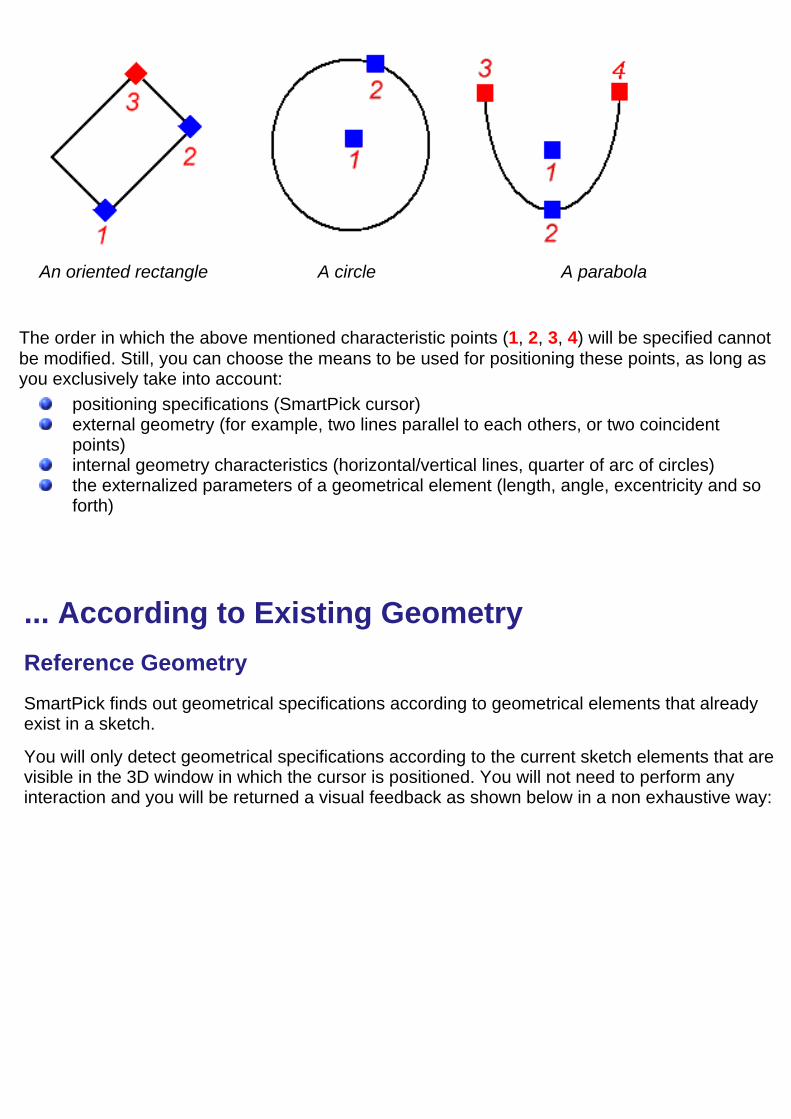
An oriented rectangle
A circle
A parabola
The order in which the above mentioned characteristic points (1, 2, 3, 4) will be specified cannotbe modified. Still, you can choose the means to be used for positioning these points, as long asyou exclusively take into account:
positioning specifications (SmartPick cursor)external geometry (for example, two lines parallel to each others, or two coincidentpoints)internal geometry characteristics (horizontal/vertical lines, quarter of arc of circles)the externalized parameters of a geometrical element (length, angle, excentricity and soforth)
... According to Existing Geometry
Reference Geometry
SmartPick finds out geometrical specifications according to geometrical elements that alreadyexist in a sketch.
You will only detect geometrical specifications according to the current sketch elements that arevisible in the 3D window in which the cursor is positioned. You will not need to perform anyinteraction and you will be returned a visual feedback as shown below in a non exhaustive way:
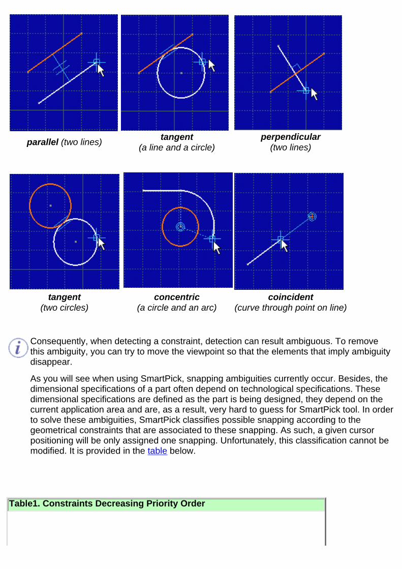
parallel (two lines)
tangent (a line and a circle)
perpendicular(two lines)
tangent
(two circles)concentric
(a circle and an arc)coincident
(curve through point on line)
Consequently, when detecting a constraint, detection can result ambiguous. To removethis ambiguity, you can try to move the viewpoint so that the elements that imply ambiguitydisappear.
As you will see when using SmartPick, snapping ambiguities currently occur. Besides, thedimensional specifications of a part often depend on technological specifications. Thesedimensional specifications are defined as the part is being designed, they depend on thecurrent application area and are, as a result, very hard to guess for SmartPick tool. In orderto solve these ambiguities, SmartPick classifies possible snapping according to thegeometrical constraints that are associated to these snapping. As such, a given cursorpositioning will be only assigned one snapping. Unfortunately, this classification cannot bemodified. It is provided in the table below.
Table1. Constraints Decreasing Priority Order
Point-to-point coincidence1. Point-to-extremity point coincidence2. Point-to-noticeable point coincidence (for example, the midpoint of a line)3. Curve-to-curve tangency4. Horizontal or vertical line, or else a quarter of an arc of a circle5. Parallelism6. Perpendicular curves7. Point-to-curve coincidence8. Curve-to-curve coincidence or point to curve support coincidence9. Point on a perpendicular line through a line end point10. Point at a vertical position11. Point at a horizontal position12.
In addition to this classification, when several snapping are possible for a given type ofgeometrical constraint, SmartPick takes into account the distance between the snapped cursorand the geometrical element according to which the snapping is possible. In this case,SmartPick snaps to the nearest element.
Still, there are some cases when SmartPick does not allow dimensioning as desired withoutadditional interactions. This is why SmartPick therefore manages two means for applying aparticular snapping relatively to the geometrical elements.
Forcing the Snapping
SmartPick allows forcing the snapping on a given geometrical element using either thecontextual menu or the Ctrl key.
Contextual Menu
SmartPick allows forcing the snapping on a given geometrical element using the contextualmenu. You will avoid ambiguities linked to the automatic detection of elements in the current 3Dviewpoint by forcing:
snapping detected at a distance: parallel, perpendicular, concentric, tangency and curve(line/circle) that goes through a point.At a distance means that these constraints are detected even though the cursor is notpositioned on the reference element.snapping at a given position that is relative to a geometrical element: line midpoint, circlecenter.At a given position means that both degrees of freedom are locked.
The contextual menu is therefore available when right-clicking most Sketcher geometricalelements. Of course, the contents of the contextual menu depends of the element that is beingcurrently created. This contextual menu can be made of the below four sub-parts:

Option that belongs to CATIA - Base infrastructure product
Snapping the characteristic point that is being manipulated (see Fromscratch paragraph and table2 below)
Snapping the geometrical element that is being created (see table3below)
Managing the parameters that are associated to the geometrical elementthat is being sketched
Popped Up Geometry: Available Snapping:
Line Line midpoint
Circle Circle center
Table2. Constraints that can be detected when snapping characteristic points currently manipulatedrelatively to existing geometrical elements and thanks to the contextual menu
Point Line Circle Ellipse Conic Spline
Point Midpoint Center No No No
Line No No No

Circle No No No
Table3. Possible snapping for geometrical element currently created relatively to existing geometry and thanksto the contextual menu
Any snapping that is imposed via the contextual menu can be de-activated. For this, right-click inthe 3D window background and select the Reset option from the displayed contextual menu.
Ctrl Key
SmartPick also allows forcing the current snapping on an element using the Ctrl key.You can force SmartPick to remain snapped on an element whatever the position of thecursor. For this, you will press the Ctrl key while the geometrical snapping you want toforce is active (the element may be highlighted and symbols may appear) and keep theCtrl key pressed.This functionality is efficient if once the Ctrl key is pressed you can still move the cursor.In other words, Ctrl has no effect if the current snapping inhibits both degrees of freedom.This is often the case when given snapping combinations are possible (for example at theintersection of two lines) or when the cursor is close to a given point (explicit or implicit asfor example the midpoint of a segment).The Ctrl key is very useful when the sketch includes many geometrical elements becauseSmartPick takes into account the distance between the cursor and the geometricalelement.
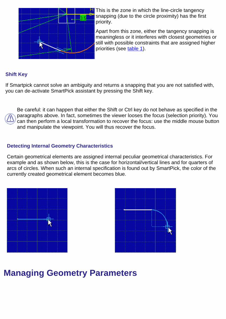
This is the zone in which the line-circle tangencysnapping (due to the circle proximity) has the firstpriority.
Apart from this zone, either the tangency snapping ismeaningless or it interferes with closest geometries orstill with possible constraints that are assigned higherpriorities (see table 1).
Shift Key
If Smartpick cannot solve an ambiguity and returns a snapping that you are not satisfied with,you can de-activate SmartPick assistant by pressing the Shift key.
Be careful: it can happen that either the Shift or Ctrl key do not behave as specified in theparagraphs above. In fact, sometimes the viewer looses the focus (selection priority). Youcan then perform a local transformation to recover the focus: use the middle mouse buttonand manipulate the viewpoint. You will thus recover the focus.
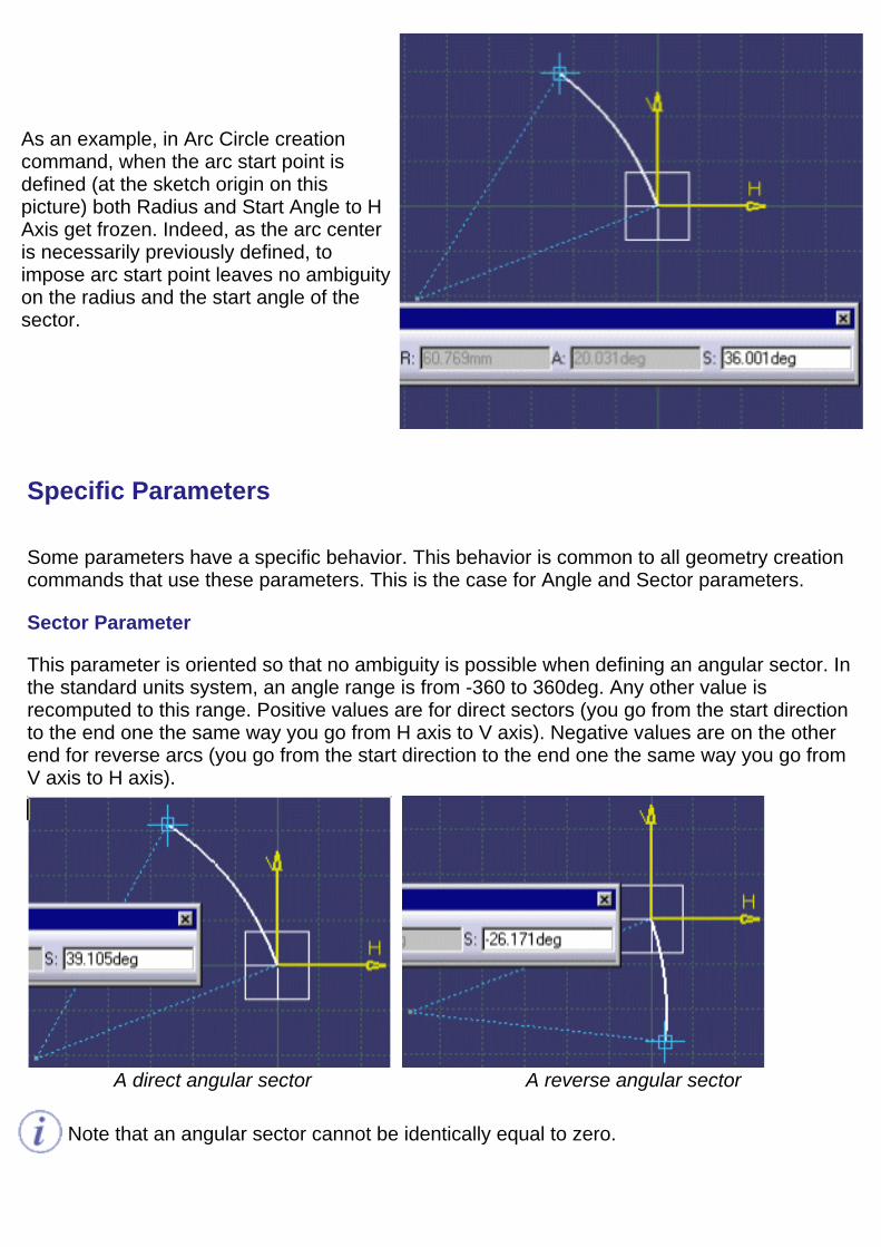
Detecting Internal Geometry Characteristics
Certain geometrical elements are assigned internal peculiar geometrical characteristics. Forexample and as shown below, this is the case for horizontal/vertical lines and for quarters ofarcs of circles. When such an internal specification is found out by SmartPick, the color of thecurrently created geometrical element becomes blue.
Managing Geometry Parameters

SmartPick also manages internal geometrical specifications such as a line length or a circleradius. Indeed, these specifications (further called parameters) decrease available degreesof freedom of a geometry characteristic point (refer to previous From Scratch paragraph).All these parameters are accessed through the Tools Toolbar which gathers all theavailable parameters that can be valuated for a given geometry creation command. Finally,while the SmartPick cursor moves, the Tools toolbar displays the parameters value.
Listed below is a non exhaustive list of the possible looks of Tools toolbar parametersection :
Length and Angle to H axis areavailable for Line creation command.
Radius, Start Angle to H Axis orAngular sector are available for ArcCircle creation command.
Excentricity is available for Hyperbolacreation command.
Note that it is always possible to reset a parameter that have been valuated in the Toolstoolbar. For this, use contextual sub-menu Reset option that is available on 3D viewerbackground.
Relation Between Parameters and Characteristic Points
There exist a strong relation between the characteristic point of a geometrical element and someof the parameters it supports. In fact, if a parameter value is modified by moving the cursor, itmeans that the parameter is linked to the current characteristic point and consequentlyvalidating the point will modify the parameter status.
Indeed, as when valuated a characteristic point can no longer be modified, associatedparameters get frozen which is echoed by a grayed entry in the Tools toolbar.
As an example, in Arc Circle creationcommand, when the arc start point isdefined (at the sketch origin on thispicture) both Radius and Start Angle to HAxis get frozen. Indeed, as the arc centeris necessarily previously defined, toimpose arc start point leaves no ambiguityon the radius and the start angle of thesector.
Specific Parameters
Some parameters have a specific behavior. This behavior is common to all geometry creationcommands that use these parameters. This is the case for Angle and Sector parameters.
Sector Parameter
This parameter is oriented so that no ambiguity is possible when defining an angular sector. Inthe standard units system, an angle range is from -360 to 360deg. Any other value isrecomputed to this range. Positive values are for direct sectors (you go from the start directionto the end one the same way you go from H axis to V axis). Negative values are on the otherend for reverse arcs (you go from the start direction to the end one the same way you go fromV axis to H axis).
A direct angular sector A reverse angular sector
Note that an angular sector cannot be identically equal to zero.
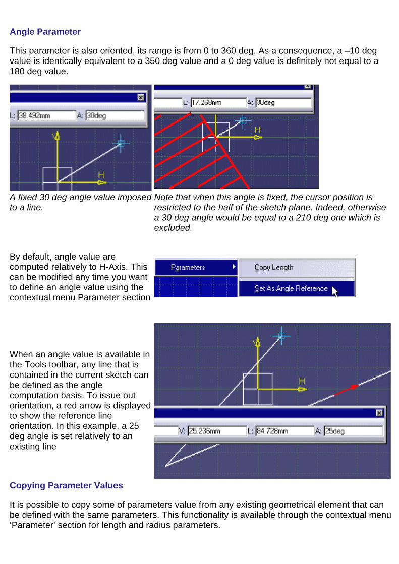
Angle Parameter
This parameter is also oriented, its range is from 0 to 360 deg. As a consequence, a –10 degvalue is identically equivalent to a 350 deg value and a 0 deg value is definitely not equal to a180 deg value.
A fixed 30 deg angle value imposedto a line.
Note that when this angle is fixed, the cursor position isrestricted to the half of the sketch plane. Indeed, otherwisea 30 deg angle would be equal to a 210 deg one which isexcluded.
By default, angle value arecomputed relatively to H-Axis. Thiscan be modified any time you wantto define an angle value using thecontextual menu Parameter section
When an angle value is available inthe Tools toolbar, any line that iscontained in the current sketch canbe defined as the anglecomputation basis. To issue outorientation, a red arrow is displayedto show the reference lineorientation. In this example, a 25deg angle is set relatively to anexisting line
Copying Parameter Values
It is possible to copy some of parameters value from any existing geometrical element that canbe defined with the same parameters. This functionality is available through the contextual menu‘Parameter’ section for length and radius parameters.

Length can be copied from a linewhile radius from a circle or an arc.

Sketching Simple ProfilesThe Sketcher workbench provides a set of functionalities for creating 2D geometryand more precisely pre-defined profiles.
Before you begin, make sure you are familiar with Tools For Sketching.
As soon as a profile is created, it appears in the specification tree.
Note that if you position the cursor outside the zone that is allowed for creating a givenelement, the symbol appears.
Create a profileUse the Tools toolbar or click to define lines and arcs which the profile maybe made of.
Create a rectangleUse the Tools toolbar or click the rectangle extremity points one after theother.
Create a circleUse the Tools toolbar or click to define the circle center and then one pointon the circle.
Create a three point circleUse the Tools toolbar or click to define the circle start point, second pointand end point one after the other.
Create a circle using coordinatesUse the Circle Definition dialog box to define the circle center point andradius.
Create a tri-tangent circleClick three elements one after the other to create a circle made of threetangent constraints.
Create an arcUse the Tools toolbar or click to define the arc center and then the arc startpoint and end point.
Create a three point arcUse the Tools toolbar or click to define the arc start point, second point andend point one after the other.
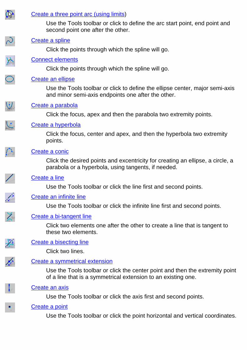
Create a three point arc (using limits)Use the Tools toolbar or click to define the arc start point, end point andsecond point one after the other.
Create a splineClick the points through which the spline will go.
Connect elementsClick the points through which the spline will go.
Create an ellipseUse the Tools toolbar or click to define the ellipse center, major semi-axisand minor semi-axis endpoints one after the other.
Create a parabolaClick the focus, apex and then the parabola two extremity points.
Create a hyperbolaClick the focus, center and apex, and then the hyperbola two extremitypoints.
Create a conicClick the desired points and excentricity for creating an ellipse, a circle, aparabola or a hyperbola, using tangents, if needed.
Create a lineUse the Tools toolbar or click the line first and second points.
Create an infinite lineUse the Tools toolbar or click the infinite line first and second points.
Create a bi-tangent lineClick two elements one after the other to create a line that is tangent tothese two elements.
Create a bisecting lineClick two lines.
Create a symmetrical extensionUse the Tools toolbar or click the center point and then the extremity pointof a line that is a symmetrical extension to an existing one.
Create an axisUse the Tools toolbar or click the axis first and second points.
Create a pointUse the Tools toolbar or click the point horizontal and vertical coordinates.

Create a point using coordinatesEnter in the Point Definition dialog box cartesian or polar coordinates.
Create an equidistant pointEnter in the Equidistant Point Definition dialog box the number and spacingof the points to be equidistantly created on a line or a curve-type element.
Create a point using intersectionCreate one or more points by intersecting curve type elements via selection.
Create a point using projectionCreate one or more points by projecting points onto curve type elements.
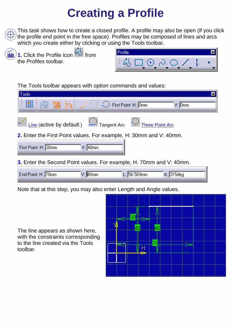
Creating a ProfileThis task shows how to create a closed profile. A profile may also be open (if you clickthe profile end point in the free space). Profiles may be composed of lines and arcswhich you create either by clicking or using the Tools toolbar.
1. Click the Profile icon fromthe Profiles toolbar.
The Tools toolbar appears with option commands and values:
Line (active by default ) Tangent Arc Three Point Arc
2. Enter the First Point values. For example, H: 30mm and V: 40mm.
3. Enter the Second Point values. For example, H: 70mm and V: 40mm.
Note that at this step, you may also enter Length and Angle values.
The line appears as shown here,with the constraints correspondingto the line created via the Toolstoolbar.

4. Press and hold the left mousebutton down.Dragging the cursor allows you toactivate the Tangent Arc modeautomatically.
A rubberbanding arc follows thecursor, showing the tangent arc tobe created.
If you cannot manage creating thetangent arc using the left mousebutton, what you can do is selectthe Tangent Arc option command
in the Tools toolbar.
5. Click the arc end point.
The Line switch is set bydefault.
6. Start dragging another line andpress the Ctrl key to lock tangencydetection.

7. Click a point to end the linecreation.
8. Select the Three Points Arc
option command from the Toolstoolbar.
At this step, in order to have a clearer sketch, we decided not to visualize theconstraints symbols temporarily (Tools->Options-> General->Parameters options atthe left on the dialog box, Symbols tab, Filter switch button).
Tangent arcs are always positionedin the direction of the elementpreviously created.
9. Click a point which the profile isgoing to go through (arc secondpoint).
10. Click a point coincident to thestart point of the line first created.You thus define the three point arcend point.

11. Activate the constraints symbolsvisualization again(Tools->Options->General->Parameters options at theleft on the dialog box, Symbols tab,Filter switch button).
The profile results as shown here:

Creating a RectangleThis task shows how to create a rectangle. In this task, we will use the Tools toolbar but, ofcourse you can create this rectangle manually. For this, move the cursor to activateSmartPick and click as soon as you get what you wish.
1. Click the Rectangle icon from theProfiles toolbar.
The Tools toolbar now displays values for defining the rectangle.
2. Position the cursor in the desired field (Tools toolbar) and key in the desired values.
First Point
For example, key in the coordinates of onecorner of the rectangle (H: 20mm and V:20mm).
Second Point
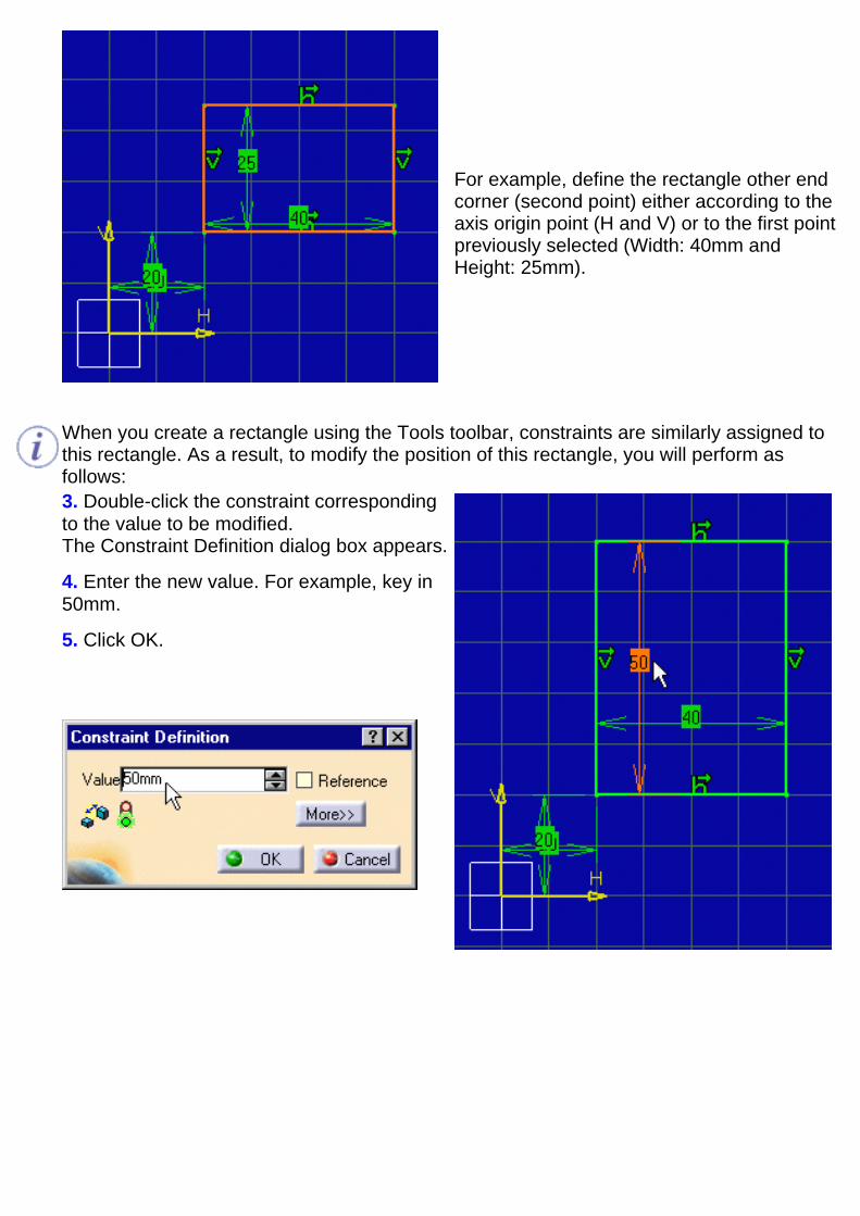
For example, define the rectangle other endcorner (second point) either according to theaxis origin point (H and V) or to the first pointpreviously selected (Width: 40mm andHeight: 25mm).
When you create a rectangle using the Tools toolbar, constraints are similarly assigned tothis rectangle. As a result, to modify the position of this rectangle, you will perform asfollows:3. Double-click the constraint correspondingto the value to be modified.The Constraint Definition dialog box appears.
4. Enter the new value. For example, key in50mm.
5. Click OK.

Creating a CircleThis task shows how to create a circle. In this task, we will use the Tools toolbar but, ofcourse you can create this circle manually. For this, move the cursor to activateSmartPick and click as soon as you get what you wish.By default, circle centers are appear on the sketch. In case you create circles byclicking, if you do not need them you can specify this in the Options dialog box.For this, go to Tools->Options, Mechanical Design -> Sketcher option (Sketcher tab).Uncheck the Create circle and ellipse centers option.
1. Click the Circle icon from the Profilestoolbar (Circle sub-toolbar).
The Tools toolbar now displays values for defining the circle.
2. Position the cursor in the desired field (Tools toolbar) and key in the desired values.
Circle Center
For example, key in values of the pointcorresponding to the circle center (H:30mm and V: 30mm).
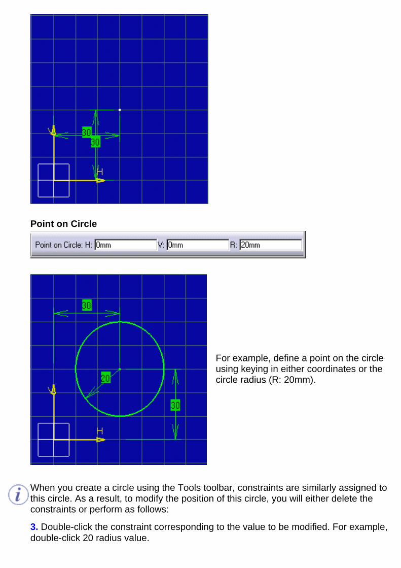
Point on Circle
For example, define a point on the circleusing keying in either coordinates or thecircle radius (R: 20mm).
When you create a circle using the Tools toolbar, constraints are similarly assigned tothis circle. As a result, to modify the position of this circle, you will either delete theconstraints or perform as follows:
3. Double-click the constraint corresponding to the value to be modified. For example,double-click 20 radius value.
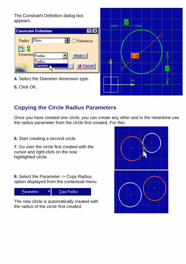
The Constraint Definition dialog boxappears.
4. Select the Diameter dimension type.
5. Click OK.
Copying the Circle Radius Parameters
Once you have created one circle, you can create any other and in the meantime usethe radius parameter from the circle first created. For this:
6. Start creating a second circle.
7. Go over the circle first created with thecursor and right-click on the nowhighlighted circle.
8. Select the Parameter -> Copy Radiusoption displayed from the contextual menu.
The new circle is automatically created withthe radius of the circle first created.
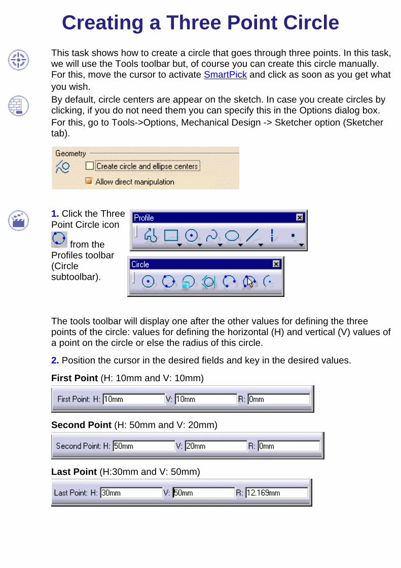
Creating a Three Point CircleThis task shows how to create a circle that goes through three points. In this task,we will use the Tools toolbar but, of course you can create this circle manually.For this, move the cursor to activate SmartPick and click as soon as you get whatyou wish.By default, circle centers are appear on the sketch. In case you create circles byclicking, if you do not need them you can specify this in the Options dialog box.For this, go to Tools->Options, Mechanical Design -> Sketcher option (Sketchertab).
1. Click the ThreePoint Circle icon
from theProfiles toolbar(Circlesubtoolbar).
The tools toolbar will display one after the other values for defining the threepoints of the circle: values for defining the horizontal (H) and vertical (V) values ofa point on the circle or else the radius of this circle.
2. Position the cursor in the desired fields and key in the desired values.
First Point (H: 10mm and V: 10mm)
Second Point (H: 50mm and V: 20mm)
Last Point (H:30mm and V: 50mm)

The three point circle appears as shown here:

Creating a Circle Using CoordinatesThis task shows how to create a circle using center point coordinates. In thisparticular case, we will use cartesian coordinates. Still, you can also use polarcoordinates.By default, circle centers appear on the sketch and are associative. In case youcreate circles by clicking, if you do not need them you can specify this in theOptions dialog box.For this, go to Tools->Options, Mechanical Design -> Sketcher option (Sketchertab).
1. Click the Circle Using
Coordinates icon from theProfiles toolbar (Circlesubtoolbar).
The Circle Definition dialog box is displayed. The default point coordinates thatappear in the Circle Definition dialog box are the origin axis coordinates.
If, before clicking the Circle Using Coordinates icon, you select a point, this pointwill be used as a reference point and the coordinates of this point will appear inthe Circle Definition dialog box.
2. Enter the coordinates of the center point.
3. Enter the desired circle radius value.

4. Press OK.
The circle and its center point are created.

Creating a Tri-Tangent CircleThis task shows how to create a tri-tangent circle by creating three tangents. In thistask, we will create this circle manually but, of course you can use the Tools toolbar.Create two circles and a line.By default, circle centers appear on the sketch and are associative. In case you createcircles by clicking, if you do not need them you can specify this in the Options dialogbox. For this, go to Tools->Options, Mechanical Design -> Sketcher option at the left ofthe dialog box (Sketcher tab).
1. Click the Tri-Tangent Circle icon from the Profiles toolbar (Circle subtoolbar).
2. Click a first element. For example, a circle.
3. Click a second element. For example, another circle.
4. Click a third element. For example, aline.
The tri-tangent circle appears as well as thecorresponding constraints provided you
activated the Internal Constraints icon .
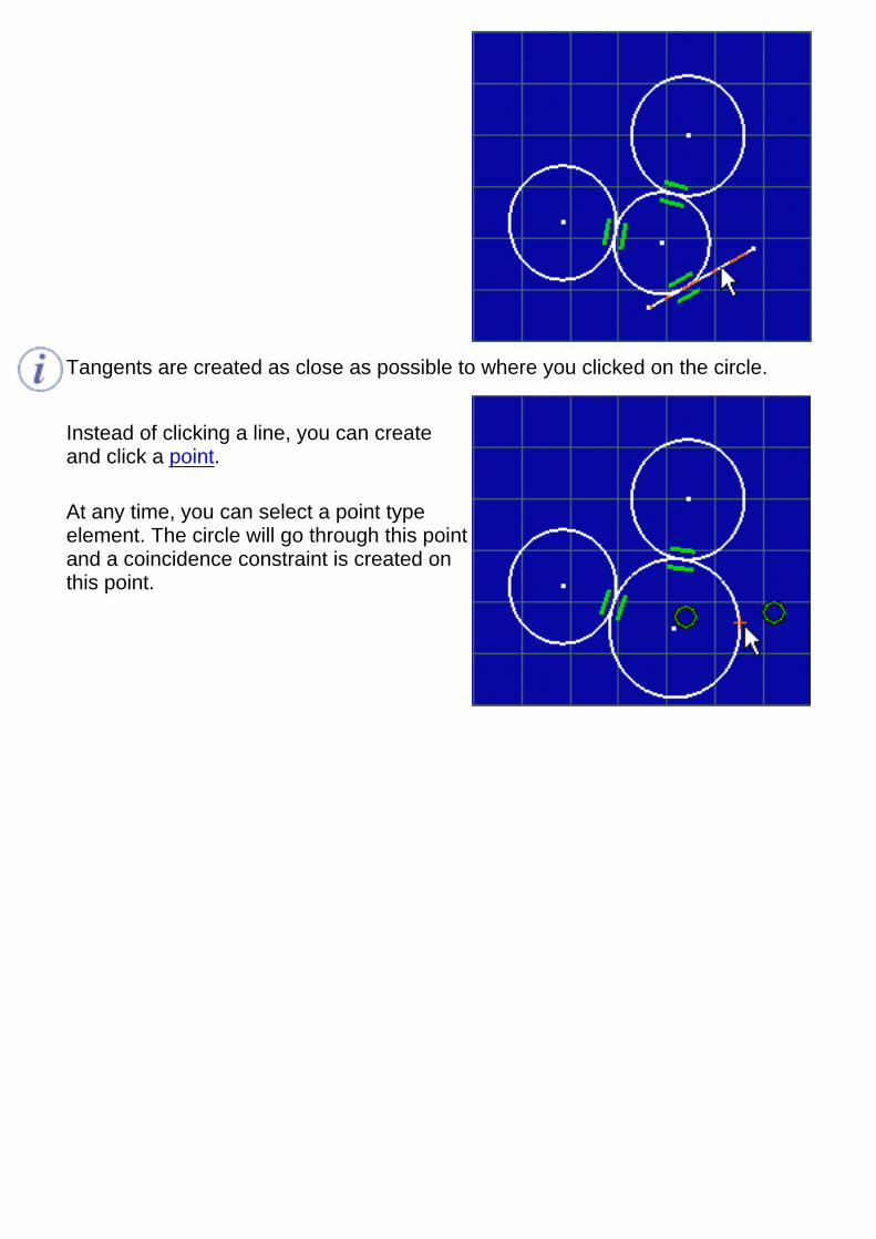
Tangents are created as close as possible to where you clicked on the circle.
Instead of clicking a line, you can createand click a point.
At any time, you can select a point typeelement. The circle will go through this pointand a coincidence constraint is created onthis point.
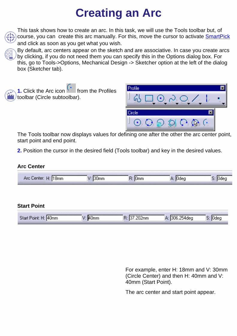
Creating an ArcThis task shows how to create an arc. In this task, we will use the Tools toolbar but, ofcourse, you can create this arc manually. For this, move the cursor to activate SmartPickand click as soon as you get what you wish.By default, arc centers appear on the sketch and are associative. In case you create arcsby clicking, if you do not need them you can specify this in the Options dialog box. Forthis, go to Tools->Options, Mechanical Design -> Sketcher option at the left of the dialogbox (Sketcher tab).
1. Click the Arc icon from the Profilestoolbar (Circle subtoolbar).
The Tools toolbar now displays values for defining one after the other the arc center point,start point and end point.
2. Position the cursor in the desired field (Tools toolbar) and key in the desired values.
Arc Center
Start Point
For example, enter H: 18mm and V: 30mm(Circle Center) and then H: 40mm and V:40mm (Start Point).
The arc center and start point appear.

The arc will now appear according to the position you assign to the cursor. In thisparticular case, the cursor position is at the bottom extremity of the arc.
End Point
For example, enter S: -70deg (AngularSector).
The arc appears as shown here.
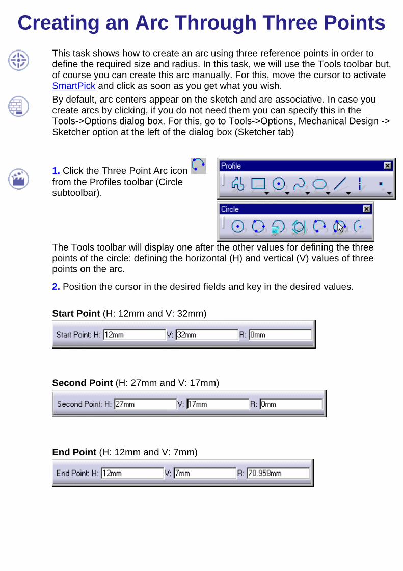
Creating an Arc Through Three PointsThis task shows how to create an arc using three reference points in order todefine the required size and radius. In this task, we will use the Tools toolbar but,of course you can create this arc manually. For this, move the cursor to activateSmartPick and click as soon as you get what you wish.By default, arc centers appear on the sketch and are associative. In case youcreate arcs by clicking, if you do not need them you can specify this in theTools->Options dialog box. For this, go to Tools->Options, Mechanical Design ->Sketcher option at the left of the dialog box (Sketcher tab)
1. Click the Three Point Arc icon from the Profiles toolbar (Circlesubtoolbar).
The Tools toolbar will display one after the other values for defining the threepoints of the circle: defining the horizontal (H) and vertical (V) values of threepoints on the arc.
2. Position the cursor in the desired fields and key in the desired values.
Start Point (H: 12mm and V: 32mm)
Second Point (H: 27mm and V: 17mm)
End Point (H: 12mm and V: 7mm)
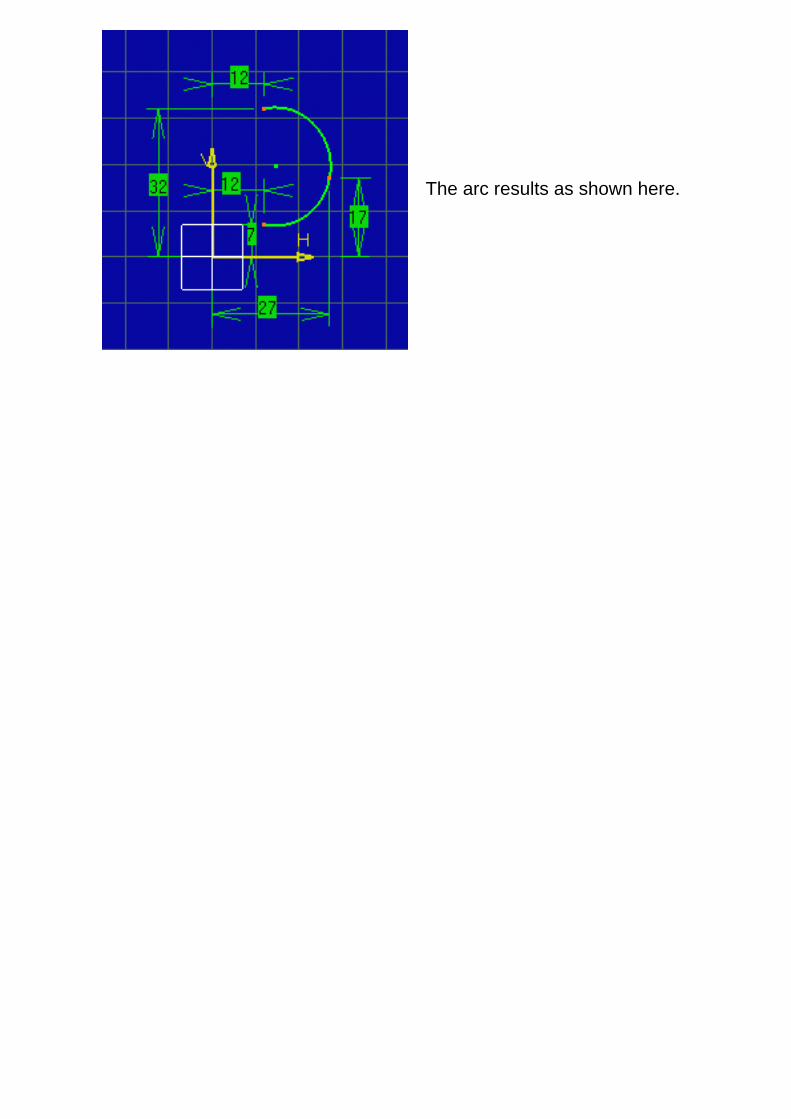
The arc results as shown here.
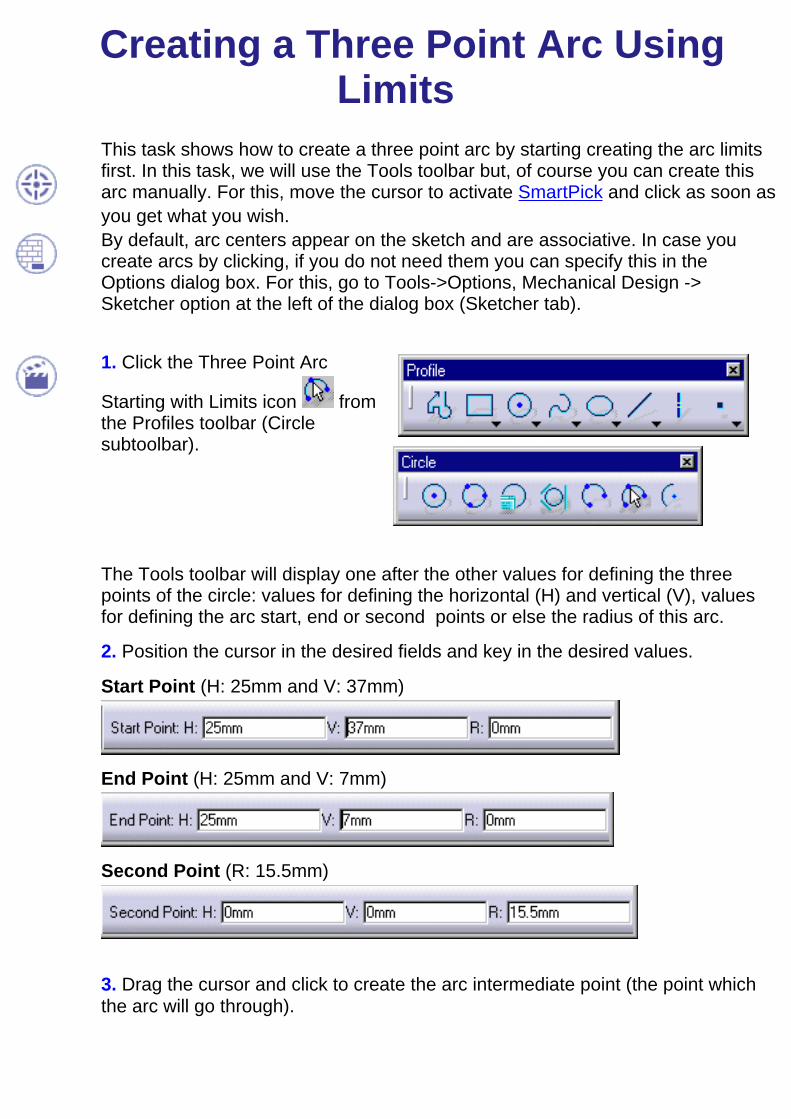
Creating a Three Point Arc UsingLimits
This task shows how to create a three point arc by starting creating the arc limitsfirst. In this task, we will use the Tools toolbar but, of course you can create thisarc manually. For this, move the cursor to activate SmartPick and click as soon asyou get what you wish.By default, arc centers appear on the sketch and are associative. In case youcreate arcs by clicking, if you do not need them you can specify this in theOptions dialog box. For this, go to Tools->Options, Mechanical Design ->Sketcher option at the left of the dialog box (Sketcher tab).
1. Click the Three Point Arc
Starting with Limits icon fromthe Profiles toolbar (Circlesubtoolbar).
The Tools toolbar will display one after the other values for defining the threepoints of the circle: values for defining the horizontal (H) and vertical (V), valuesfor defining the arc start, end or second points or else the radius of this arc.
2. Position the cursor in the desired fields and key in the desired values.
Start Point (H: 25mm and V: 37mm)
End Point (H: 25mm and V: 7mm)
Second Point (R: 15.5mm)
3. Drag the cursor and click to create the arc intermediate point (the point whichthe arc will go through).

The three point arc appears asshown here:
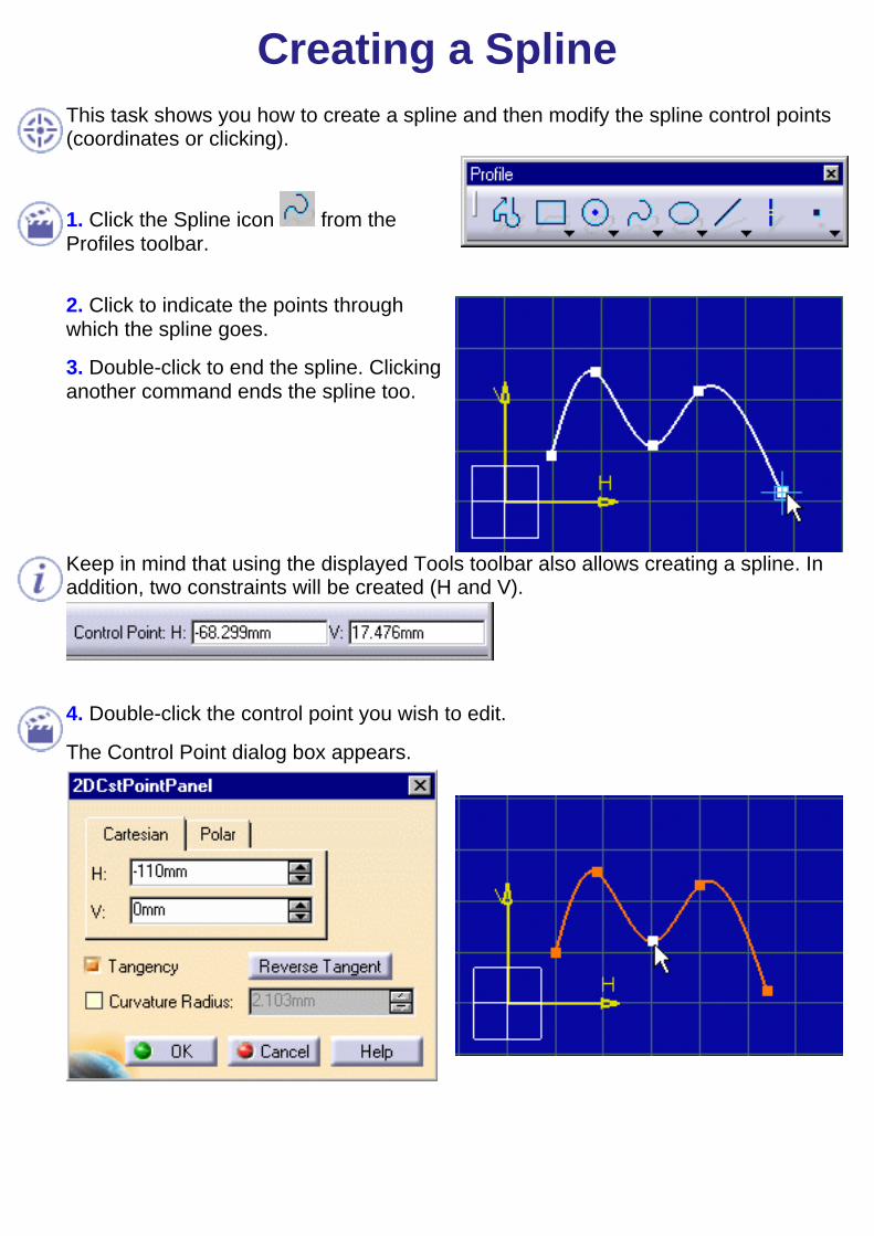
Creating a SplineThis task shows you how to create a spline and then modify the spline control points(coordinates or clicking).
1. Click the Spline icon from theProfiles toolbar.
2. Click to indicate the points throughwhich the spline goes.
3. Double-click to end the spline. Clickinganother command ends the spline too.
Keep in mind that using the displayed Tools toolbar also allows creating a spline. Inaddition, two constraints will be created (H and V).
4. Double-click the control point you wish to edit.
The Control Point dialog box appears.

5. Enter new coordinates. For example, v:9mm (vertical).
6. Check the Tangency option to impose atangency on this control point.You can invert the tangent directionclicking the Reverse tangent button.
7. Click OK.The point is moved and an arrow appearson this point to indicate a tangency.
You can also check the Curvature option to activate the Curvature editor and impose acurvature on the previously selected control point.
Keep in mind that selecting a point then dragging it will modify the spline shape.
Tangents can be constrained.

Connecting ElementsThis task shows you how to connect two curve type elements using either with an arcor a spline.
Open the Connect_Spline.CATPart document.
1. Click the Connect icon from the
Profiles toolbar (Spline subtoolbar).
Two connect option commands appear inthe Tools toolbar.
The Connect With Arc option command isactive by default.
2. Select a first element (starting point).
3. Select a second element (ending point).
A connecting arc appears, tangent to bothselected elements.
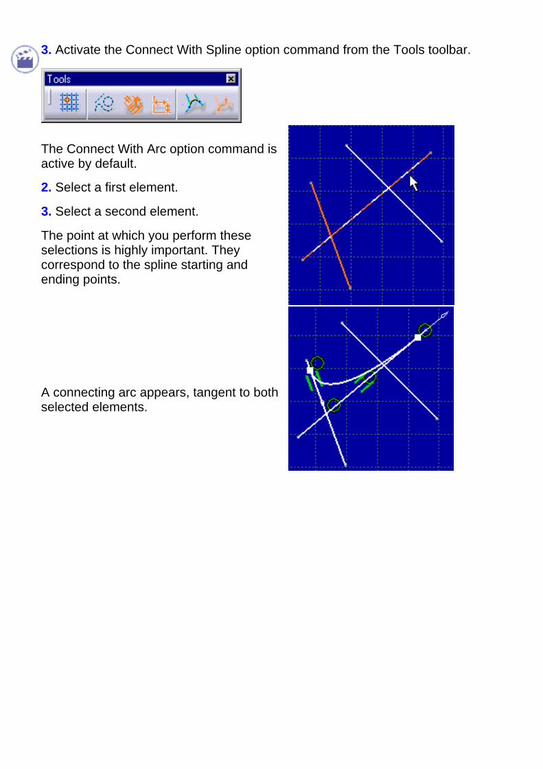
3. Activate the Connect With Spline option command from the Tools toolbar.
The Connect With Arc option command isactive by default.
2. Select a first element.
3. Select a second element.
The point at which you perform theseselections is highly important. Theycorrespond to the spline starting andending points.
A connecting arc appears, tangent to bothselected elements.

Creating an EllipseThis task shows how to create an ellipse (made of two infinite axes). In this task, we willuse both the Tools toolbar and clicking. In other words, you will move the cursor toactivate SmartPick and click as soon as you get what you wish.
1. Click the Ellipse icon from theProfiles toolbar.
The Tools toolbar displays values for defining the ellipse center point, major and thenminor semi-axis endpoint.
2. Position the cursor in the desired fields and key in the desired values.
Center
For example, enter H: 9mm and V: 8mm.
Note that you can also click to create afirst point that corresponds to the ellipsecenter.
Major Semi-Axis Endpoint

For example, enter H: 65mm and V: 8mm.
You just created a point on the ellipse.This point allows defining the majorsemi-axis.
By default, centers are created and associative but if you do not need them you canspecify this in the Tools -> Options dialog box. For more information, see BaseInfrastructure user's guide.
3. Move the cursor and click a point on the ellipse.You just created a point which allows defining both minor semi-axes.
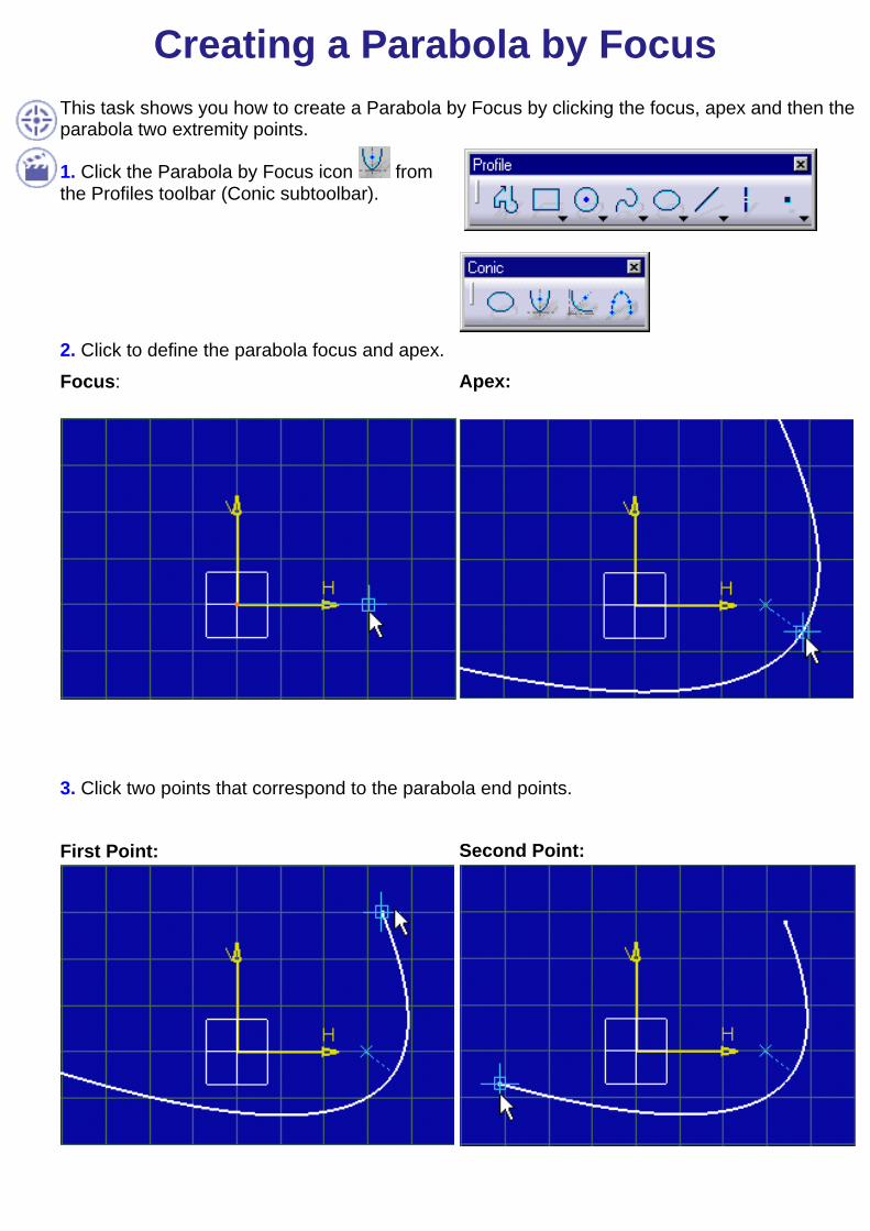
Creating a Parabola by FocusThis task shows you how to create a Parabola by Focus by clicking the focus, apex and then theparabola two extremity points.
1. Click the Parabola by Focus icon fromthe Profiles toolbar (Conic subtoolbar).
2. Click to define the parabola focus and apex.Focus: Apex:
3. Click two points that correspond to the parabola end points.
First Point:
Second Point:
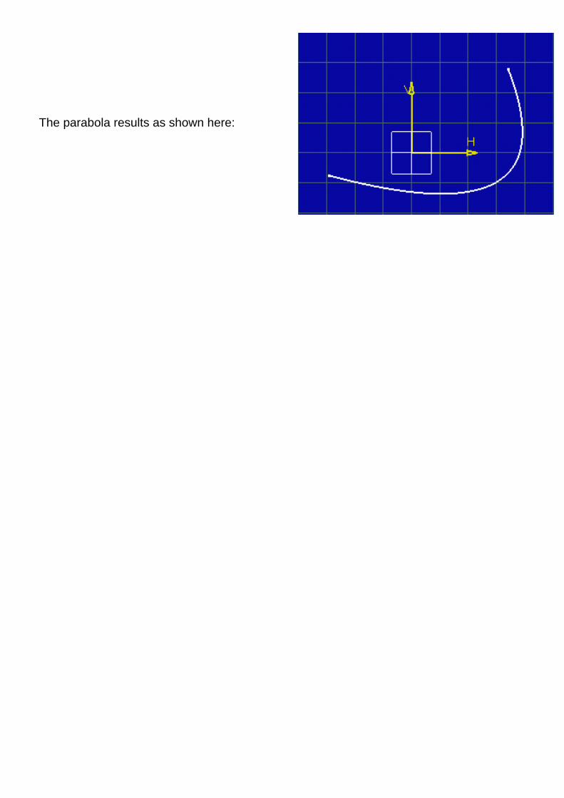
The parabola results as shown here:
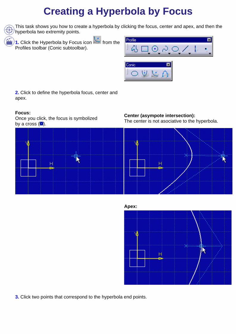
Creating a Hyperbola by FocusThis task shows you how to create a hyperbola by clicking the focus, center and apex, and then thehyperbola two extremity points.
1. Click the Hyperbola by Focus icon from theProfiles toolbar (Conic subtoolbar).
2. Click to define the hyperbola focus, center andapex.
Focus:Once you click, the focus is symbolizedby a cross ( ).
Center (asympote intersection):The center is not asociative to the hyperbola.
Apex:
3. Click two points that correspond to the hyperbola end points.
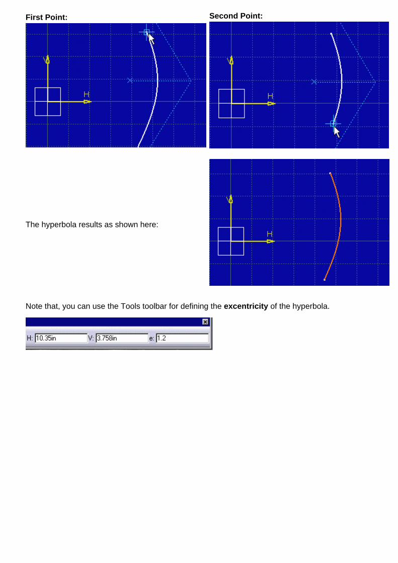
First Point: Second Point:
The hyperbola results as shown here:
Note that, you can use the Tools toolbar for defining the excentricity of the hyperbola.
Creating a ConicThis task shows how to create a conic type element by clicking desired points and, if needed,using tangents or entering the excentricity into the Tools toolbar. As a result, you will create oneof the following: an ellipse, a circle, a parabola or a hyperbola.
You will click/select points at the end and on the curve in one of the following ways:Five points Four points and one tangentThree points and two tangentsThree points, two tangents and keyed in excentricity
1. Click the Conics icon from the
Profiles toolbar (Conic subtoolbar).
The Tools toolbar will display one after the other values for defining the conic end points, otherpoints, if needed, the tangent coordinate points and the excentricity.
2. Click a first end point.
At this step or even at the begin of the task, you can activate the option from the Toolstoolbar and assign a tangent to the point first selected.
3. Click a second end point.
At this step or even at the begin of the task, you can activate the option from the Toolstoolbar and assign a tangent to the point selected.
You can also select the option from the Tools toolbar and assign a tangent to both selected
points.
4. If you assigned at most tangents to both end points, click a point on the conic.
At this step, in case you actually assigned tangents to both end points, this point will correspondto the conic excentricity and can be either clicked or keyed in the Tools toolbar. For this activatethe option from the Tools toolbar.

5. If you assigned at most a tangent to one end point, click a second point on the conic.
6. If you assigned no tangent to the end points, click a third point on the conic.
... Using Five Points 1. Five points (end points and then points on curve)
2. Final conic
... Four Points and One Tangent 1. First end point (tangent) 2. End point
3. Two points on curve
4. Final conic
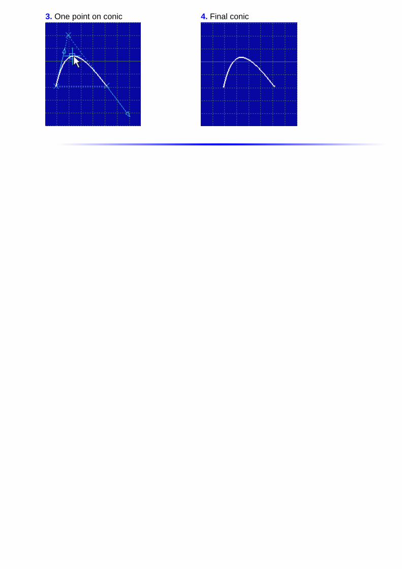
... Three Points and Two Tangents
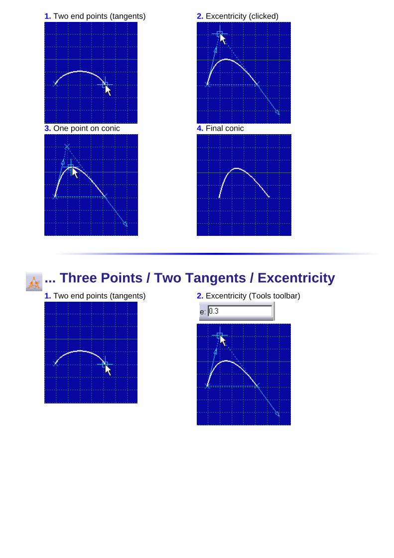
1. Two end points (tangents) 2. Excentricity (clicked)
3. One point on conic 4. Final conic
... Three Points / Two Tangents / Excentricity 1. Two end points (tangents) 2. Excentricity (Tools toolbar)
3. One point on conic 4. Final conic
Creating a LineThis task shows how to create a line. In this task, we will use the Tools toolbar but, ofcourse you can create this line manually. For this, move the cursor to activateSmartPick and click as soon as you get what you wish.
1. Click the Line icon from the Profilestoolbar.
The Tools toolbar now displays values for defining the rectangle.
Thanks to the Symmetrical Extension icon , you can create a line that issymmetrical to its origin.
First Point
2. Click the line first point (first point).
3. Position the cursor in the desired field (Tools toolbar) and key in the desired values.
Second Point
You can define the second point eitheraccording to the axis origin point (H and V)or to a given length (L) and angle (A).
For example, key in L: 30mm and A:45deg.
4. Press Enter.

When you create a line using the Tools toolbar, constraints are similarly assigned to
this line (by default, the Internal Constraints icon is active). As a result, to modifythe position of this line, you will perform as follows:
5. Double-click the constraint corresponding to the value to be modified.
The Constraint Definition dialog box appears.
6. Enter the new value. For example, usethe spinner and assign a 30deg value to theline.
7. Click OK.
Care when you assign graphical attributes to a line (for example, make it thick and red).When you turn this red thick line into a construction line (from the contextual menu:Object.Line -> Definition..., Construction line option in the Line Definition dialog box),the line will become a dotted gray line. Even though you then decide to make it astandard line back again (un-checking the Construction line option), the "red" and"thickness" attributes will not be assigned to the line. The line will be assigned itsoriginal attributes (white).
Defining Line Length/Angle Parameters
Once you have created one line, you can create any other and in the meantime use thelength from the line first created or set this first line as an angle reference. For this:

8. Start creating a new line.
9. Go over the line first created with thecursor and right-click on the nowhighlighted line.
10. Select the Parameters-> Copy Lengthoption displayed in the contextual menu.
The new line is automatically created withthe length of the line first created.
11. Start creating a new line.
12. Go over the line first created with thecursor and right-click on the nowhighlighted line.
13. Select the Set As Angle Reference option displayed in the contextual menu.
14. Enter the desired angle value in the Tools toolbar. For example, 75 degrees.
The new line is automatically created with an angle defined relatively to the lineselected (in this particular case, the second line).
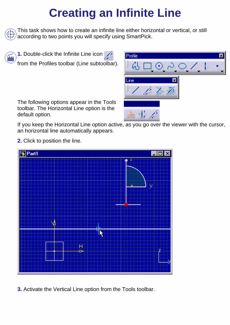
Creating an Infinite LineThis task shows how to create an infinite line either horizontal or vertical, or stillaccording to two points you will specify using SmartPick.
1. Double-click the Infinite Line icon
from the Profiles toolbar (Line subtoolbar).
The following options appear in the Toolstoolbar. The Horizontal Line option is thedefault option.
If you keep the Horizontal Line option active, as you go over the viewer with the cursor,an horizontal line automatically appears.
2. Click to position the line.
3. Activate the Vertical Line option from the Tools toolbar.

As you go over the viewer with the mouse, a vertical line now automatically appears.
4. Click to position the line.
5. Activate the Line Through Two Points option from the Tools toolbar.
Note that the angle (A) now appears in the Tools toolbar and can be valued at any timefor defining the line.
6. Click to position a start point on the infinite line to be created.
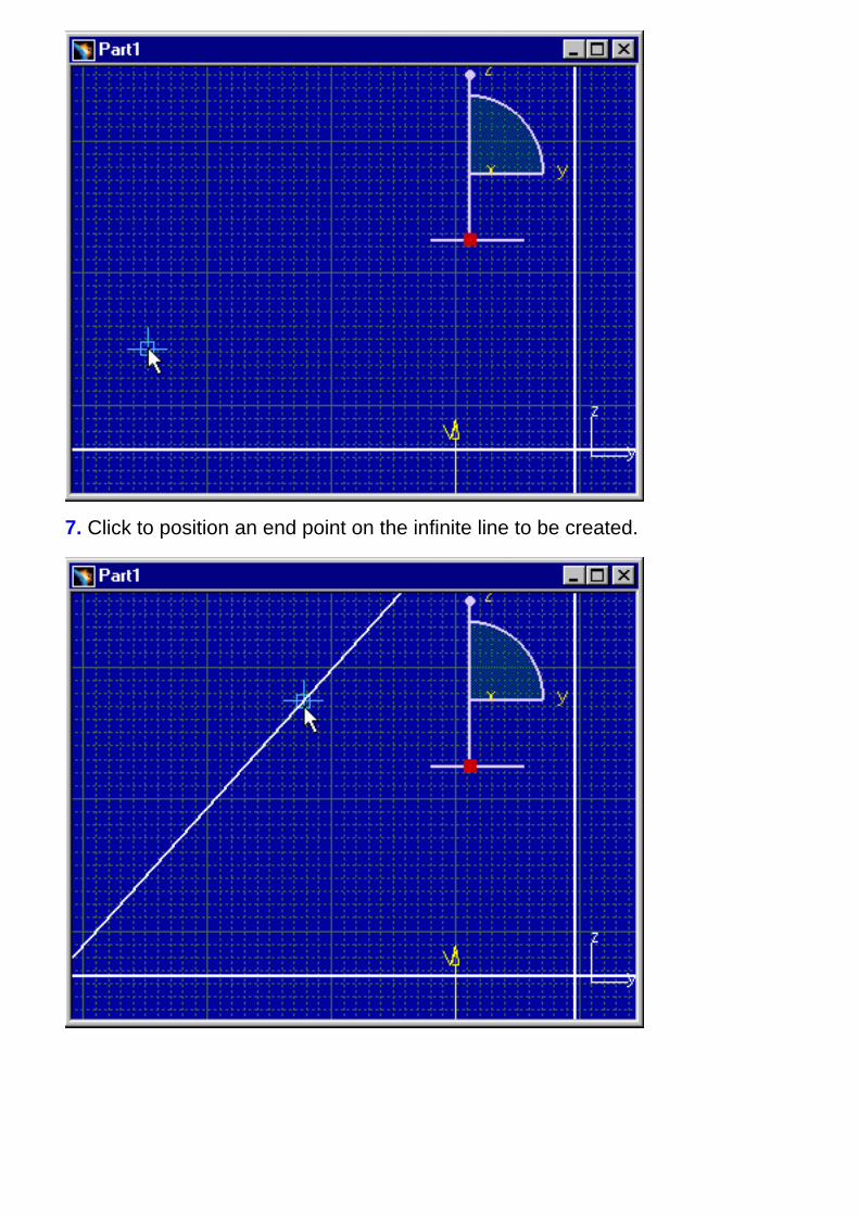
7. Click to position an end point on the infinite line to be created.

Creating a Bi-Tangent LineThis task shows how to create a bi-tangent line by creating two tangents (on twodifferent elements).
Create two circles.
1. Click the Bi-Tangent Line icon fromthe Profiles toolbar (Line subtoolbar).
2. Click a first element (first tangent). Forexample, click a circle.
3. Click a second element (secondtangent). For example, click another circle.
The bi-tangent line appears between bothselected elements.
The bi-tangent line appears as well as thecorresponding constraints provided youactivated the Geometrical Constraints icon
.
Tangents are created as close as possible to where you clicked on the circle.

At this step, create a point.
At any time, you can select a point typeelement. The line will go through this pointand a coincidence constraint is created onthis point.
Creating a Bisecting LineThis task shows how to create an infinite bisecting line by clicking two points on twoexisting lines.
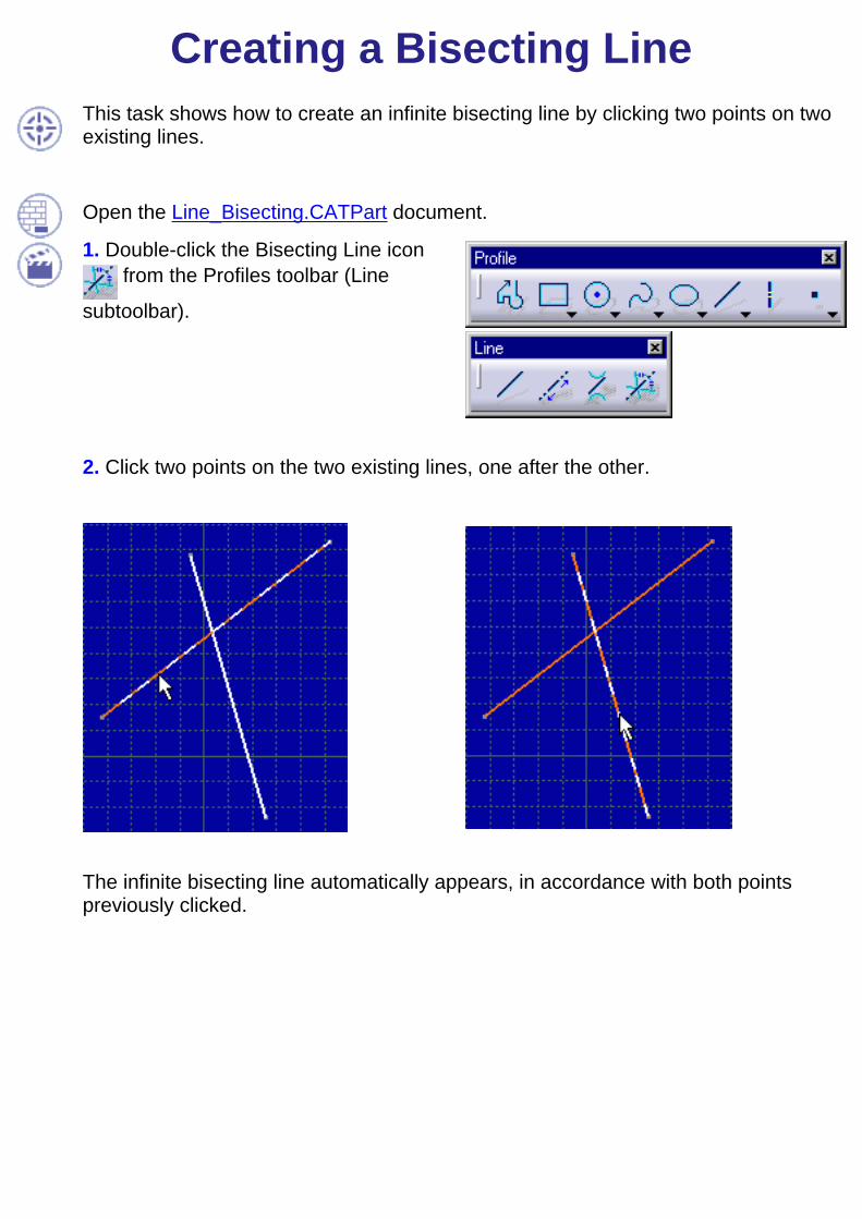
Open the Line_Bisecting.CATPart document.
1. Double-click the Bisecting Line icon from the Profiles toolbar (Line
subtoolbar).
2. Click two points on the two existing lines, one after the other.
The infinite bisecting line automatically appears, in accordance with both pointspreviously clicked.

Note that this bisecting line corresponds to a line symmetrically constrained to twolines (of course on the condition the Geometrical Constraint option command is
active in the Tools toolbar). If both selected lines are parallel to each others, a newline will be created between these lines.

Creating a Symmetrical ExtensionThis task shows how to create a symmetrical extension to a line. In other words, you aregoing to create a median to an existing line by clicking. Still, you can use the Tools toolbar.
Create a line.
1. Click the Line icon from the Profilestoolbar.
2. Click the Symmetrical Extension command option that appears in the Tools toolbar.
3. Click the center point of the line which is to beassigned a symmetrical extension.
4. Drag the cursor to the desired location.
The median appears. It is perpendicular to theline, at the line midpoint.
5. Click to locate the symmetrical extension.
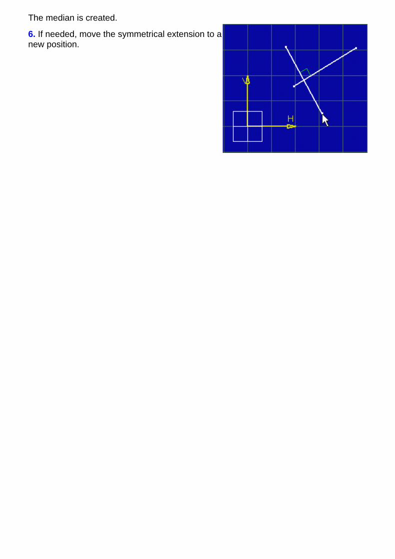
The median is created.
6. If needed, move the symmetrical extension to anew position.
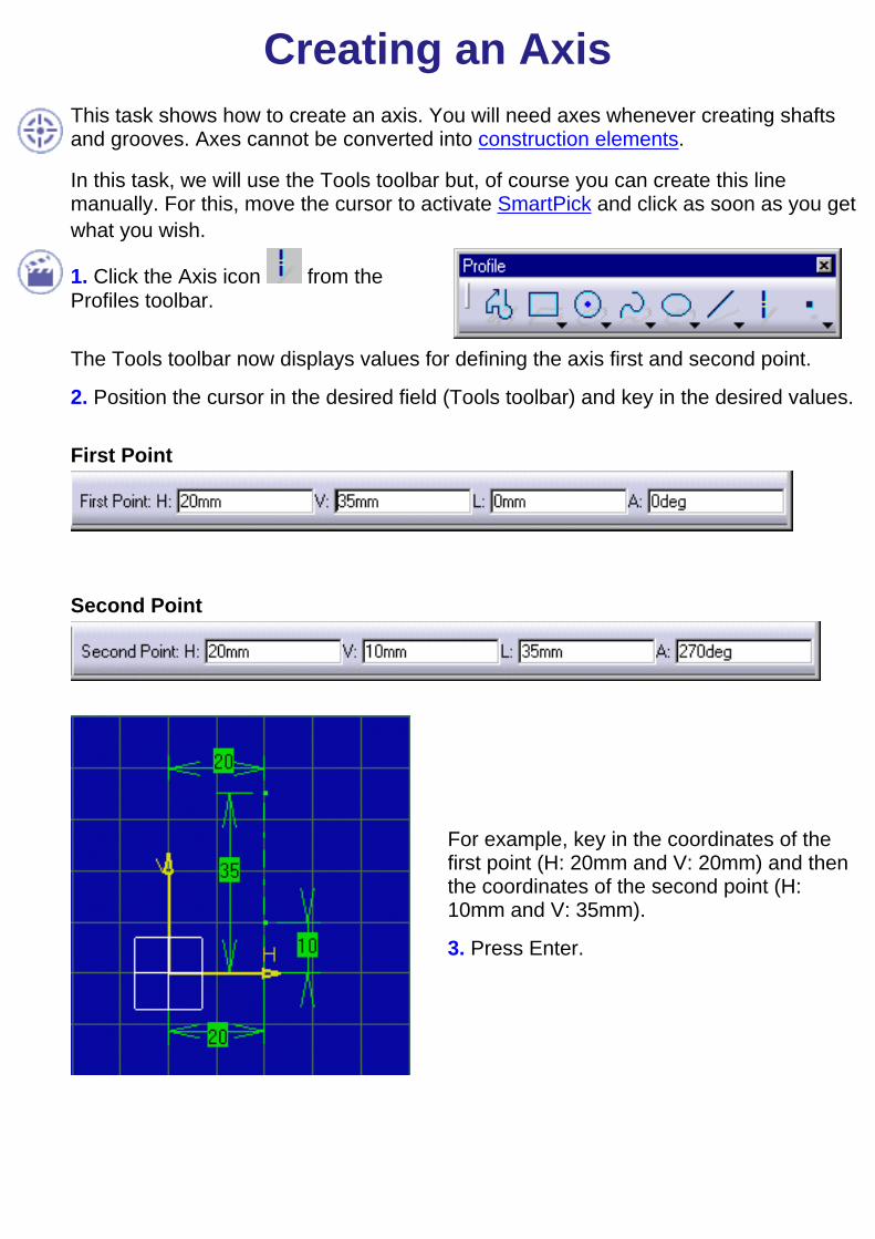
Creating an AxisThis task shows how to create an axis. You will need axes whenever creating shaftsand grooves. Axes cannot be converted into construction elements.
In this task, we will use the Tools toolbar but, of course you can create this linemanually. For this, move the cursor to activate SmartPick and click as soon as you getwhat you wish.
1. Click the Axis icon from theProfiles toolbar.
The Tools toolbar now displays values for defining the axis first and second point.
2. Position the cursor in the desired field (Tools toolbar) and key in the desired values.
First Point
Second Point
For example, key in the coordinates of thefirst point (H: 20mm and V: 20mm) and thenthe coordinates of the second point (H:10mm and V: 35mm).
3. Press Enter.
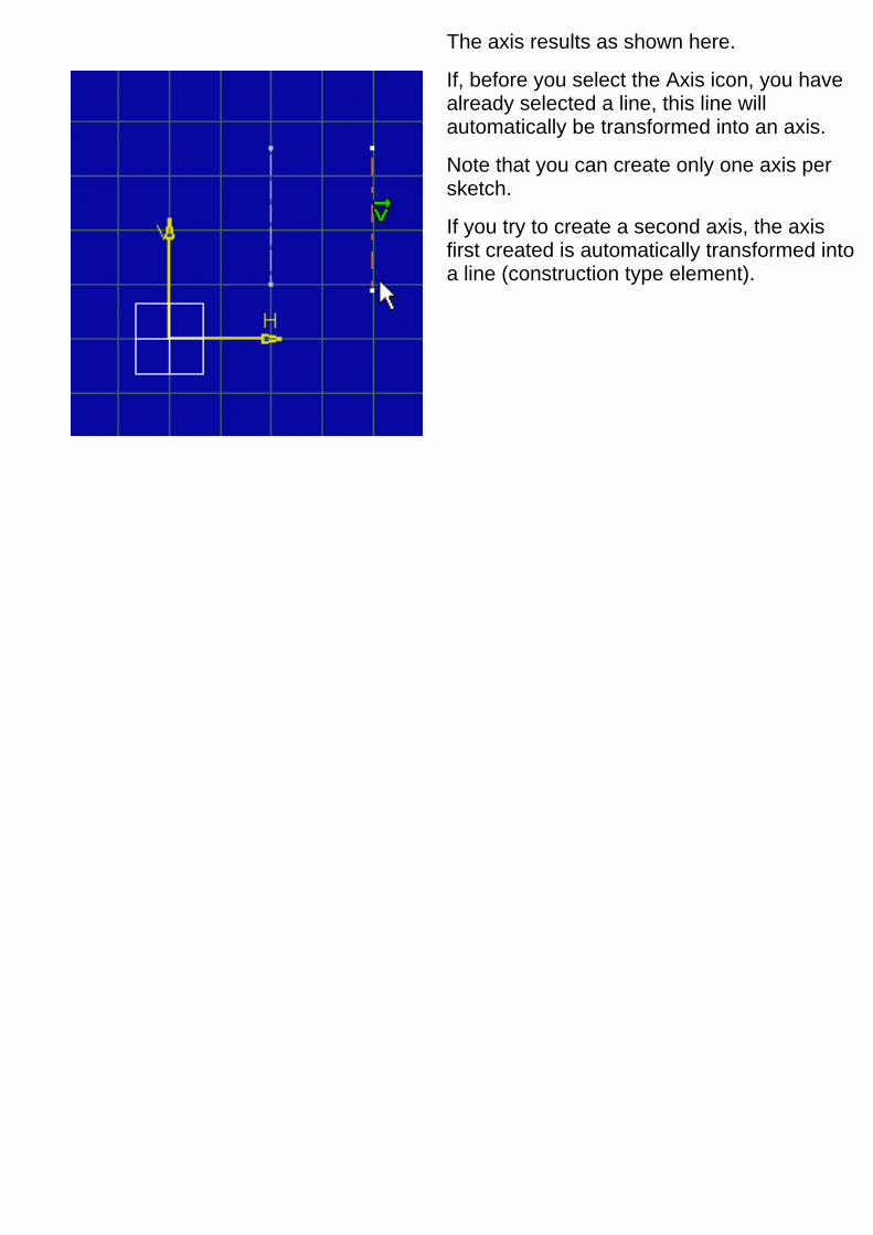
The axis results as shown here.
If, before you select the Axis icon, you havealready selected a line, this line willautomatically be transformed into an axis.
Note that you can create only one axis persketch.
If you try to create a second axis, the axisfirst created is automatically transformed intoa line (construction type element).

Creating a PointThis task shows you how to create a point. In this task, we will use the Tools toolbarbut, of course you can create this point manually. For this, move the cursor to activateSmartPick and click as soon as you get what you wish.
1. Click the Point icon from theProfiles toolbar.
The Tools toolbar displays values for defining the point coordinates: H (horizontal)and V (vertical).
2. Position the cursor in the desired field and key in the desired values.
Point Coordinates
For example, key in H: 19.7mm and V:19.5mm.
The point appears.
When you create a point using the Tools toolbar, constraints are similarly assigned tothis point. As a result, to modify the position of this point, you will either delete theconstraints or perform as follows:
3. Double-click the constraint corresponding to the value to be modified. Forexample,19.7.

The Constraint Definition dialog boxappears.
4. Modify the value in the Constraint Definition dialog box. In this case, enter Value:20mm.
5. Right-click the point and select the Properties option from the contextual menu(Graphic tab).
6. If needed, click a new symbol.
For creating an isobarycenter, click (or multi-select) at least two points before clickingthe Point command. Note that an isobarycenter can only be created between points.In other words, if you multi-select a rectangle, the four points of this rectangle, andonly these four points, will be used for defining the isobarycenter. Associativity is nomore valid.
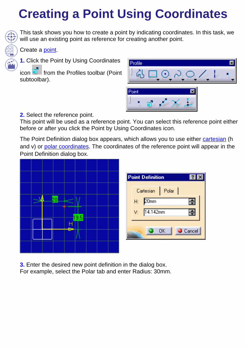
Creating a Point Using CoordinatesThis task shows you how to create a point by indicating coordinates. In this task, wewill use an existing point as reference for creating another point.
Create a point.
1. Click the Point by Using Coordinates
icon from the Profiles toolbar (Pointsubtoolbar).
2. Select the reference point.This point will be used as a reference point. You can select this reference point eitherbefore or after you click the Point by Using Coordinates icon.
The Point Definition dialog box appears, which allows you to use either cartesian (hand v) or polar coordinates. The coordinates of the reference point will appear in thePoint Definition dialog box.
3. Enter the desired new point definition in the dialog box.For example, select the Polar tab and enter Radius: 30mm.
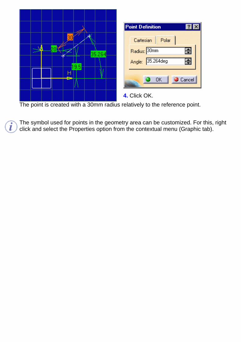
4. Click OK.The point is created with a 30mm radius relatively to the reference point.
The symbol used for points in the geometry area can be customized. For this, rightclick and select the Properties option from the contextual menu (Graphic tab).
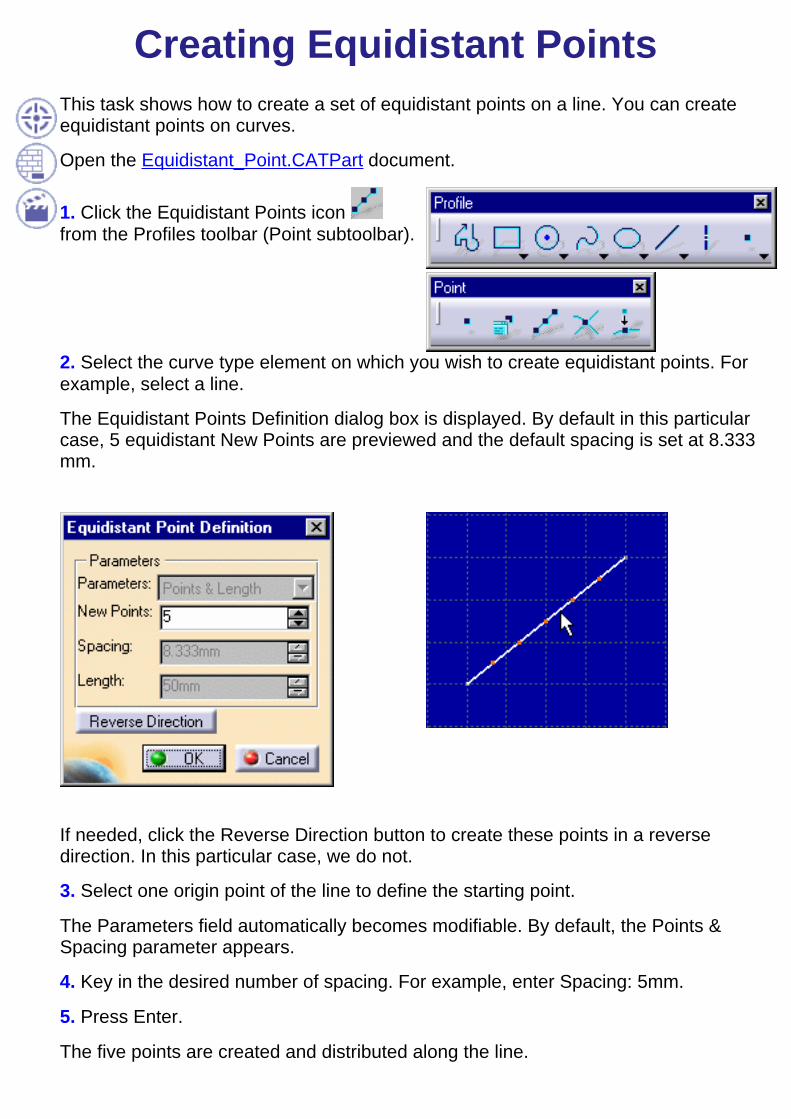
Creating Equidistant PointsThis task shows how to create a set of equidistant points on a line. You can createequidistant points on curves.
Open the Equidistant_Point.CATPart document.
1. Click the Equidistant Points icon from the Profiles toolbar (Point subtoolbar).
2. Select the curve type element on which you wish to create equidistant points. Forexample, select a line.
The Equidistant Points Definition dialog box is displayed. By default in this particularcase, 5 equidistant New Points are previewed and the default spacing is set at 8.333mm.
If needed, click the Reverse Direction button to create these points in a reversedirection. In this particular case, we do not.
3. Select one origin point of the line to define the starting point.
The Parameters field automatically becomes modifiable. By default, the Points &Spacing parameter appears.
4. Key in the desired number of spacing. For example, enter Spacing: 5mm.
5. Press Enter.
The five points are created and distributed along the line.
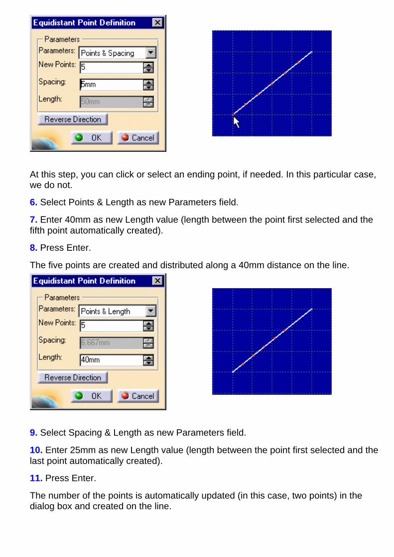
At this step, you can click or select an ending point, if needed. In this particular case,we do not.
6. Select Points & Length as new Parameters field.
7. Enter 40mm as new Length value (length between the point first selected and thefifth point automatically created).
8. Press Enter.
The five points are created and distributed along a 40mm distance on the line.
9. Select Spacing & Length as new Parameters field.
10. Enter 25mm as new Length value (length between the point first selected and thelast point automatically created).
11. Press Enter.
The number of the points is automatically updated (in this case, two points) in thedialog box and created on the line.

12. Select Spacing & Length as new Parameters field.
13. Enter 5mm as new Spacing value (spacing between each point of a distancedefines as 25mm).
14. Press Enter.
The number of the points is automatically updated (in this case, four points) in thedialog box and created on the line.
15. Click Ok to create the points (and the constraint, if needed).

Coincidence constraints will be created between each point and the line on thecondition the Dimensional Constraints command is active. Offset constraints arecreated between the points. The offset between the origin point and the firstpoint is a driving constraint.Note also that formulas are created. For more information about formulas, seeKnowledge Advisor User's guide.You can edit points one after the other. For this, double click one point andredefine either the Cartesian or the polar coordinates from the Point Definitiondialog box that appears.Modifications applied to the supporting element are not applied to points. Thesymbol used for points in the geometry area can be customized using the Edit-> Properties command (Graphic tab).

Creating a Point Using IntersectionThis task shows you how to create one or more points by intersecting curve typeelements.
Open the Intersection_Point.CATPart document.
1. Multi-select the elements to be used for intersecting.
2. Click the Intersection Point icon
from the Profiles toolbar (Point subtoolbar).
3. Select one curve type element with which the elements first selected will intersectand on which intersection points will be created.
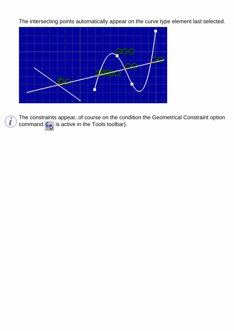
The intersecting points automatically appear on the curve type element last selected.
The constraints appear, of course on the condition the Geometrical Constraint optioncommand is active in the Tools toolbar).

Creating a Point Using ProjectionThis task shows you how to create one or more points by projecting points onto curvetype elements.
Open the Projection_Point.CATPart document.
1. Multi-select the elements to be used for projection.
2. Click the Projection Point icon from
the Profiles toolbar (Point subtoolbar).
3. Select one curve type element on which the element first selected will be projectedand on which projection points will be created.
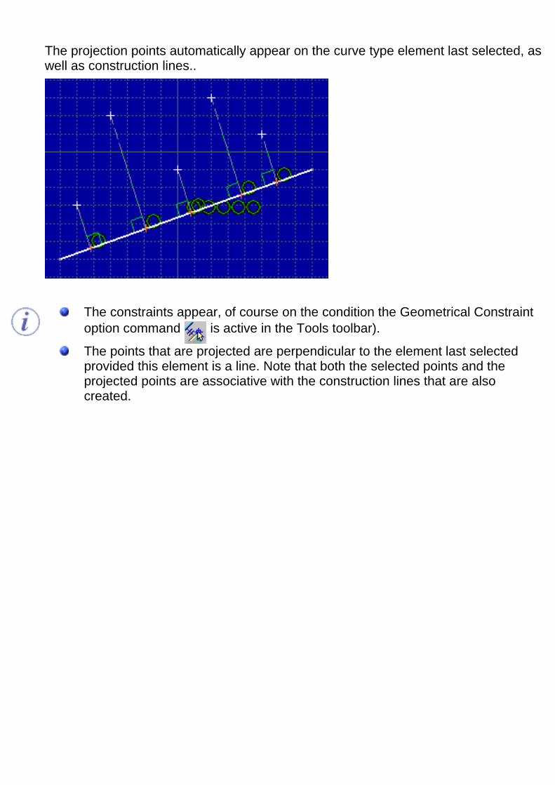
The projection points automatically appear on the curve type element last selected, aswell as construction lines..
The constraints appear, of course on the condition the Geometrical Constraintoption command is active in the Tools toolbar).
The points that are projected are perpendicular to the element last selectedprovided this element is a line. Note that both the selected points and theprojected points are associative with the construction lines that are alsocreated.
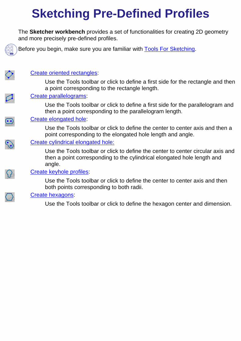
Sketching Pre-Defined ProfilesThe Sketcher workbench provides a set of functionalities for creating 2D geometryand more precisely pre-defined profiles.
Before you begin, make sure you are familiar with Tools For Sketching.
Create oriented rectangles:
Use the Tools toolbar or click to define a first side for the rectangle and thena point corresponding to the rectangle length.
Create parallelograms:Use the Tools toolbar or click to define a first side for the parallelogram andthen a point corresponding to the parallelogram length.
Create elongated hole:Use the Tools toolbar or click to define the center to center axis and then apoint corresponding to the elongated hole length and angle.
Create cylindrical elongated hole:Use the Tools toolbar or click to define the center to center circular axis andthen a point corresponding to the cylindrical elongated hole length andangle.
Create keyhole profiles:Use the Tools toolbar or click to define the center to center axis and thenboth points corresponding to both radii.
Create hexagons:Use the Tools toolbar or click to define the hexagon center and dimension.

Creating an Oriented RectangleThis task shows how to create a rectangle in the direction of your choice by definingthree extemity points of the rectangle. In this task, we will use the Tools toolbar but, ofcourse you can create this oriented rectangle manually. For this, move the cursor toactivate SmartPick and click as soon as you get what you wish.1. Click the Oriented Rectangle icon
from the Profiles toolbar (Predefined
Profile subtoolbar).
The tools toolbar now displays values for defining the first side of the orientedrectangle (both points) and then either one point on the second side or directly theoriented rectangle height.
2. Position the cursor in the desired field (Tools toolbar) and key in the desired values.
First Corner
For example, key in the coordinates of thefirst point on the first rectangle side (H:20mm and V: 20mm) or first corner.
Second Corner
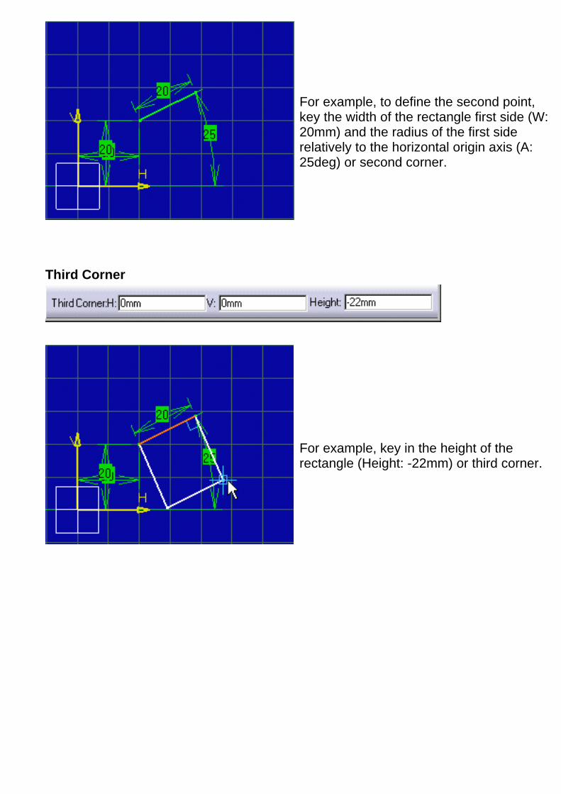
For example, to define the second point,key the width of the rectangle first side (W:20mm) and the radius of the first siderelatively to the horizontal origin axis (A:25deg) or second corner.
Third Corner
For example, key in the height of therectangle (Height: -22mm) or third corner.

3. Click to create the oriented rectangle.
The oriented rectangle and correspondingconstraints appear as shown here.

Creating a ParallelogramThis task shows how to create a parallelogram by clicking. In this task, we will use theTools toolbar but, of course you can create this parallelogram manually. For this, movethe cursor to activate SmartPick and click as soon as you get what you wish.
1. Click the Parallelogram icon from theProfiles toolbar (Predefined Profilesubtoolbar).
The tools toolbar now displays values for defining the parallelogram.
2. Position the cursor in the desired field (Tools toolbar) and key in the desired values.
First Point
For example, key in the coordinates of thefirst point on the parallelogram first side (H:20mm and V: 20mm).
Second Point

For example, key in the coordinates of thesecond point on the parallelogram first side(H: 37mm and V: 10mm).
Third Point
For example, key in the coordinates of thethird point on the parallelogram, in otherwords, on the second side of thisparallelogram (H: 57mm and V: 10mm).
3. Click to create the parallelogram.
The parallelogram and correspondingconstraints appear as shown here.

Creating an Elongated HoleThis task shows how to create an elongated hole by clicking. In this task, we will use the Tools toolbar but,of course you can create this elongated hole manually. For this, move the cursor to activate SmartPickand click as soon as you get what you wish.
1. Click the Elongated Hole icon from the Profilestoolbar (Predefined Profile subtoolbar).
The tools toolbar now displays values for defining the elongated hole center to center axis (first andsecond center point) and then either the elongated hole radius or a point on this elongated hole.
2. Position the cursor in the desired field (Tools toolbar) and key in the desired values.
First Center
Second Center
For example, key in the coordinates of bothcenter points of the elongated hole: a first point (H: 20mm and V: 18mm) and a second point (H:50mm and V: 18mm).
You just defined the profile major axis usingpoints. What you can also do is enter both thelength and angle of this axis.
Point on Oblong Profile

For example, key in the coordinates of a point onthe elongated hole (H: 53mm and V: 10mm).
In other words, you just defined the profile minoraxis or the elongated hole width applying a givenradius to the profile extremity.
At this step, what you can also do is enter theelongated hole radius.
The elongated hole appears as shown here.
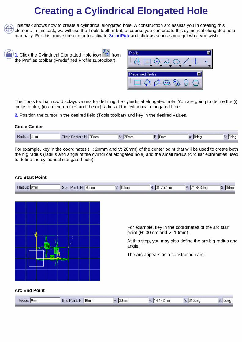
Creating a Cylindrical Elongated HoleThis task shows how to create a cylindrical elongated hole. A construction arc assists you in creating thiselement. In this task, we will use the Tools toolbar but, of course you can create this cylindrical elongated holemanually. For this, move the cursor to activate SmartPick and click as soon as you get what you wish.
1. Click the Cylindrical Elongated Hole icon fromthe Profiles toolbar (Predefined Profile subtoolbar).
The Tools toolbar now displays values for defining the cylindrical elongated hole. You are going to define the (i)circle center, (ii) arc extremities and the (iii) radius of the cylindrical elongated hole.
2. Position the cursor in the desired field (Tools toolbar) and key in the desired values.
Circle Center
For example, key in the coordinates (H: 20mm and V: 20mm) of the center point that will be used to create boththe big radius (radius and angle of the cylindrical elongated hole) and the small radius (circular extremities usedto define the cylindrical elongated hole).
Arc Start Point
For example, key in the coordinates of the arc startpoint (H: 30mm and V: 10mm).
At this step, you may also define the arc big radius andangle.
The arc appears as a construction arc.
Arc End Point

For example, key in the coordinates of the arc endpoint (H: 10mm and V: 30mm).
At this step, you may also define the arc big radius(R) and angle (A).
Point on Cylindrical Elongated Hole
For example, key in the coordinates of a point on thecylindrical elongated hole (H: 20mm and V: 20mm).
In other words, you are defining what we call the smallradius (Radius: 14.142mm). This small radiuscorresponds to the width of the cylindrical elongatedhole, relatively to the circle center.

Creating a Keyhole ProfileThis task shows how to create a keyhole profile. In this task, we will use the Toolstoolbar but, of course you can create this keyhole manually. For this, move the cursorto activate SmartPick and click as soon as you get what you wish.
1. Click the Keyhole Profile icon from the Profiles icon (PredefinedProfile subtoolbar).
The tools toolbar now displays values for defining the keyhole profile.2. Position the cursor in the desired field (Tools toolbar) and key in the desired values.First Center
Second Center
For example, key in the coordinates that willallow to define the center to center axis (Firstcenter point: H: 20mm and V: 20mm, Secondcenter point: H. 20mm and V: 40mm).
2. Click to define the first radius and then the second radius.
First radius Second radius
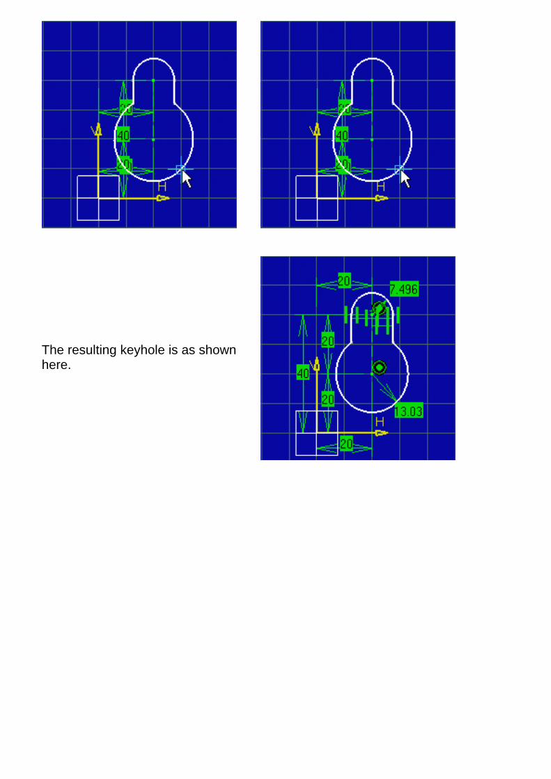
The resulting keyhole is as shownhere.

Creating an HexagonThis task shows you how to create an hexagon. A construction circle assists you in creating thisprofile. In this task, we will use the Tools toolbar but, of course you can create this hexagonmanually. For this, move the cursor to activate SmartPick and click as soon as you get what youwish.
1. Click the Hexagon icon from the Profilesicon (Predefined Profile subtoolbar).
The tools toolbar now displays values for defining the hexagon center and then either a point onthis hexagon or the hexagon dimension and angle.
2. Position the cursor in the desired field (Tools toolbar) and key in the desired values.
Hexagon Center
For example, key in the coordinates of the centerof the hexagon (H: 25mm and V: 25mm).
Point on Hexagon

For example, key in the dimension (35mm) andAngle (10deg) of the hexagon. j
The hexagon is created.
Be careful: if you fix one extremity of the hexagon and try to move the hexagon using anotherextremity point, this hexagon can result twisted. To avoid this, you must drag the hexagon step bystep releasing the mouse button regularly.
Editing ProfilesThe Sketcher workbench provides a set of functionalities for editing 2D geometry.
For information about applying constraints, refer to Setting Constraints.
Modify Element Coordinates
Double-click to modify the sketch coordinates and thereby modify thefeature defined on this sketch.
Edit a Spline:Double-click on the spline to edit it and modify it.
Edit an element Parents/Children and ConstraintsRight-click on the element end select Parents/Children... option in thecontextual menu.
Edit Projection/Intersection MarksEdit Projection/Intersection Marks definition and modify their importproperties.
Transform ProfilesUse selection to edit the profile shape and size, modify the profilelocation (via external constraints).
Perform Auto-Search on a ProfileUse the menu bar to auto-search for the different elements of aprofile.
Replace GeometryReplace geometry in the 2D and visualize it in the 3D.
Delete Sketcher ElementsUse selection to delete elements.

Setting ConstraintsYou can set geometrical and dimensional constraints on various types of elements.
Before you Begin
You should be familiar with important concepts.Create quick dimensional/geometrical constraints
Set constraints on elements or between two or three elements. Theconstraints are in priority dimensional. Use the contextual menu to get othertypes of constraints and to position this constraint as desired.
Define constraint measure directionDefine the measure direction as you create a dimensional constraint.
Create contact constraintsApply a constraint with a relative positioning that can be compared tocontact. You can either select the geometry or the command first. Use thecontextual menu if you want to insert constraints that are not those createdin priority.
Modify constraint definitionDouble-click a constraint a modify the definition using the ConstraintDefinition dialog box.
Create constraints using a dialog boxSet various geometrical constraints between one or more elements using adialog box and if needed, multi-selection.
Modify constraints on/between elementsEdit geometrical constraints defined on elements or between elementseither in the Sketcher or in the 3D area.
Autoconstrain a group of elementsDetects possible constraints between selected elements and imposes theseconstraints once detected.
Animate constraintsAssign a set of values to the same angular constraint and examine how thewhole system is affected.

Modifying Element CoordinatesThis task shows you how to modify a line. Modifying your sketch coordinates will affectthe feature defined on this sketch. In other words, associativity remains valid.
Create a line.
Profiles are not considered as entities when it comes to editing them. To edit a profile,you will need to edit the sub-elements composing it.
Multi-selection is not allowed for editing Sketcher elements.
1. Double-click the line you wish to edit.
The Line Definition dialog box appears indicating the line end point coordinates.
2. Enter new coordinatesfor changing the end pointsand/or the length andangle.
3. Check the ConstructionElements option, if youwish to change the linetype.
4. Press OK.
Remember that the Edit -> Properties command, or Properties option in the contextualmenu lets you access and edit sketch properties (properties dialog box)

Editing a SplineThis task shows you how to edit spline properties and then modify, add or remove thespline control points.Create a spline and a point.
1. Double-click on the spline or go to edit -> Spline.1 object -> Definition....The following dialog box appears:
Adding a point
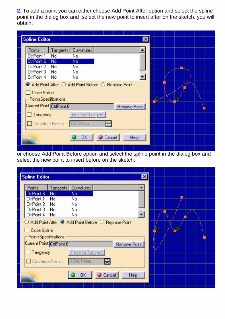
2. To add a point you can either choose Add Point After option and select the splinepoint in the dialog box and select the new point to insert after on the sketch, you willobtain:
or choose Add Point Before option and select the spline point in the dialog box and select the new point to insert before on the sketch:
Replace a point2. To replace a point, select the Replace Point option and select the point you want toreplace on the spline in the dialog box and the point that will replace it on the sketch:
Close spline2. You can also close the spline choosing the Close Spline option:
Remove a point
2. To remove a point select the point you want to remove in the dialog box and click onthe Remove Point button.
Define a tangent
2. Select the point you want to add a tangent in the dialog box.
3. Check the Tangency option.A tangent appears, you can reverse it clicking on the Reverse Tangent button.
4. If needed, check the Curvature Radius option and key in the value.
Editing Parents/Children and ConstraintsThis task shows you how to edit an element Parents/Children and Constraints.
Open the Analyse.CATPart document.
1. Right-click on the element you want to edit Parents, Children and Constraints. As anexample, select the distance constraint.
2. Select Parents/Children... in the contextual menu.The following dialog box appears:
You can double-click to expand Parents or right-click and select the Parents/Children... optionin the contextual menu on this dialog box elements to edit their Parents/Children andconstraints .
Editing Projection/Intersection MarksThis task shows you how to edit an element Parents/Children and Constraints.
Open the Analyse2.CATPart document.
Edit mark definition1. In the Sketcher (choose the sketch.2), double-click on the mark (yellow line) youwant to edit the definition or in the tree go to PartBody -> Sketch.2 -> Use-edges ->Projection.4 and double-click on Mark.1.
2. The following dialog box appears:
It allows you to visualize the mark characteristics and to transform the mark in aconstruction element.
Edit and modify mark import properties1. Expand the Tree and double-click on Projection.4 in PartBody -> Sketch.2 ->Use-edges. The Import Definition dialog box appears.
2. Choose the new reference element, in this example an arc.

A warning informs you that to take in account the modification you must exit andreenter sketcher.
3. After reentering the sketcher, the mark reference and position are changed.

Transforming ProfilesThis task shows you how to
transform profile shape and size using the Selection command.transform a profile position according to a pre-defined solving modetransform a profile position using existing external constraints
Open the Transform_replace01.CATPart document.
Transforming By MovingMinimum Move
You will move as few elements as possible. Go to Tools -> Options -> Sketcher (Solving mode switch button) andmake sure you activated the Minimum move option from the Dragging of the element dialog box.
1. Click the Select icon .
2. Drag the right line of the profile anywhere to the right.
The profile is stretched to the right if you stretch it to theright.
3. Click one corner of the profile and stretch this profilediagonally.
Standard Mode
You will move as many elements as possible. Go to Tools-> Options -> Sketcher (Solving mode switch button) andmake sure you activated the Standard mode option fromthe Dragging of the element dialog box.
1. Click the Select icon .
2. Drag the right line of the profile anywhere to the right.
The profile is stretched both to the right and to the top evenif you stretch it to the right.
Relaxation
Go to Tools -> Options -> Sketcher (Solving mode switch button) and make sure you activated the Relaxationoption from the Dragging of the element dialog box.
You can also edit the profile shape and size using commands such as edit, trim and break .
If you want the profile to revert to its original shape, click the Undo command .
If the Grid option is on (Tools -> Options -> Sketcher), you can also modify the profile using the grid. In thiscase, and for example if the Zoom is on, the point you select will be automatically repositioned at the closestgrid intersection point. The profile new position may result awkward.
Transforming Using Constraints
1. Click the Select icon .
2. Double -click the dimensional constraint.
3. Enter 20mm as new value in the Constraint Definitiondialog box that appears.
The external constraint is re-computed and the geometry is re-positioned.
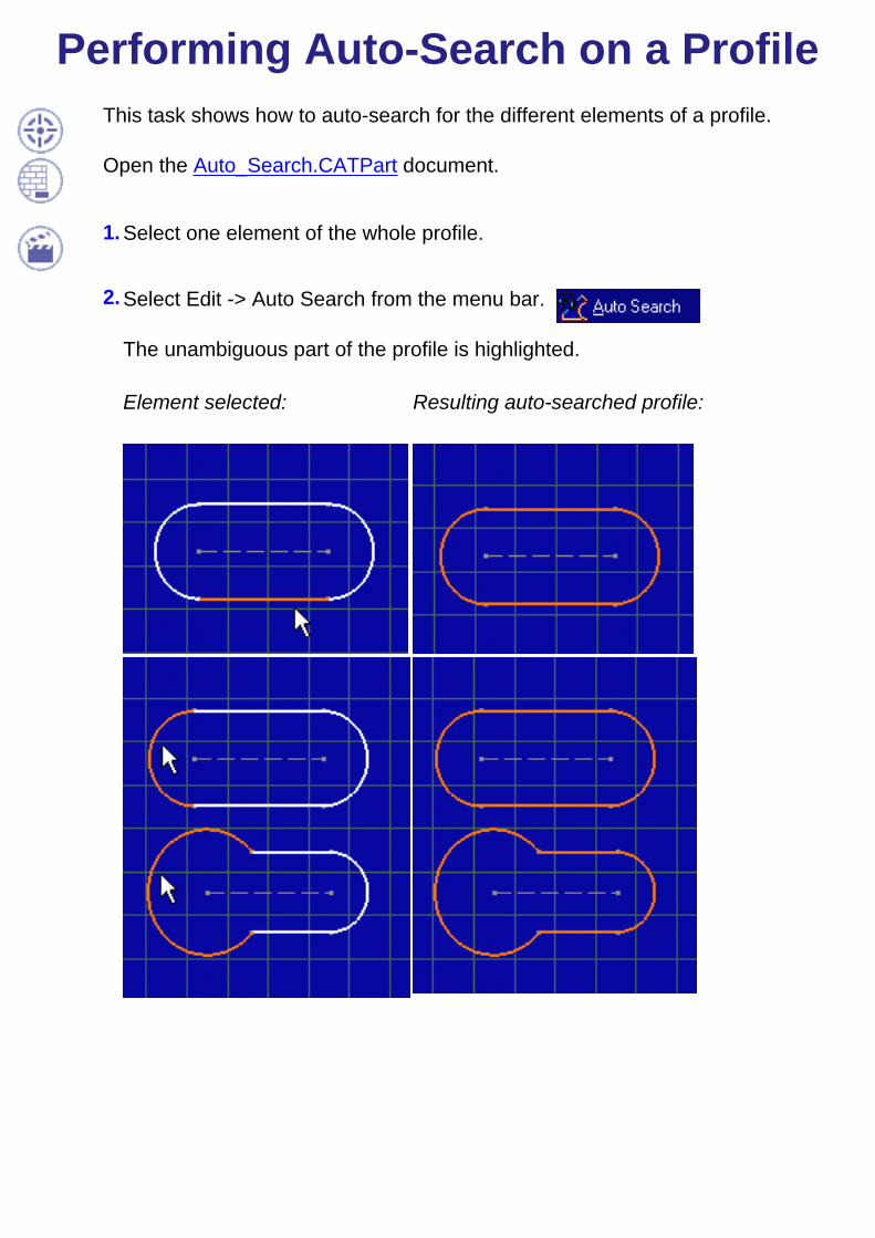
Performing Auto-Search on a ProfileThis task shows how to auto-search for the different elements of a profile.
Open the Auto_Search.CATPart document.
1. Select one element of the whole profile.
2. Select Edit -> Auto Search from the menu bar.
The unambiguous part of the profile is highlighted.
Element selected: Resulting auto-searched profile:
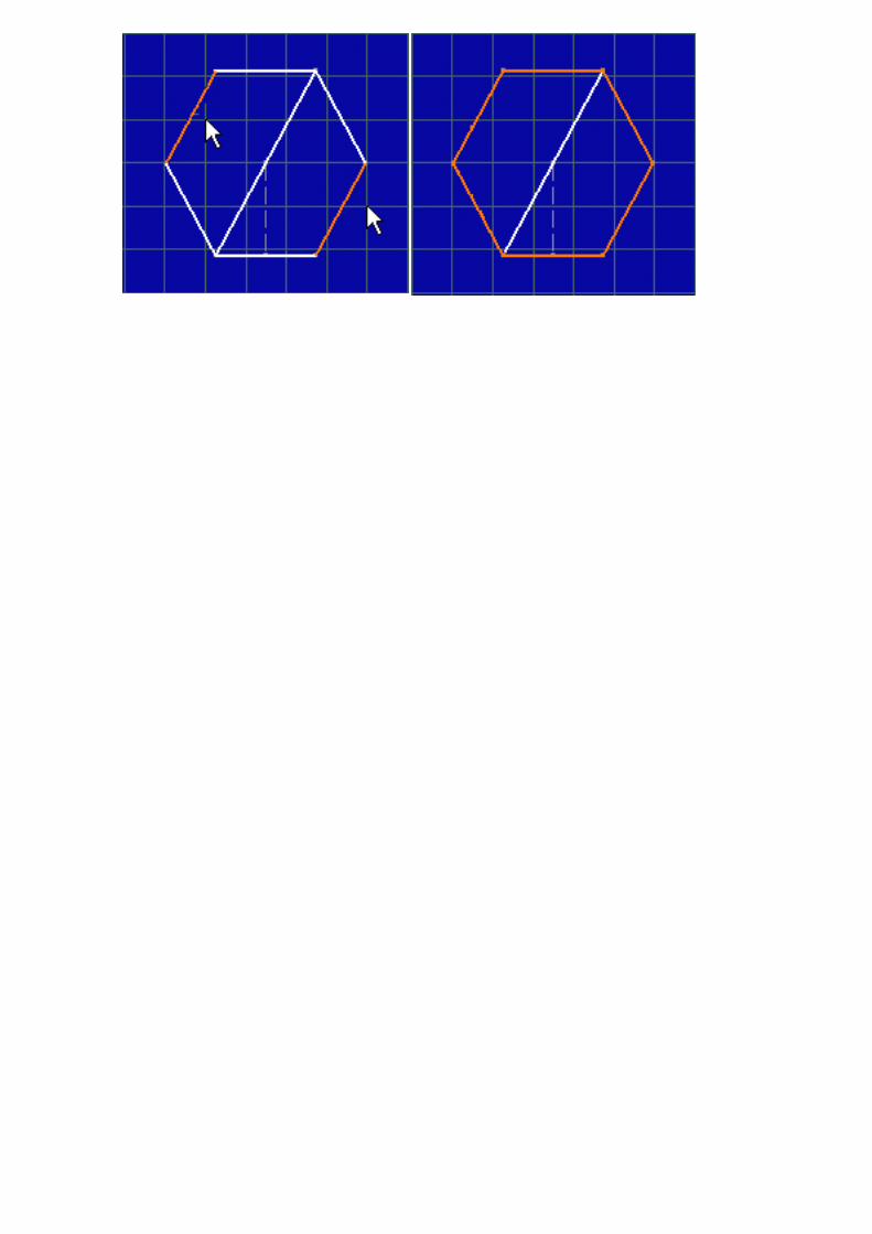
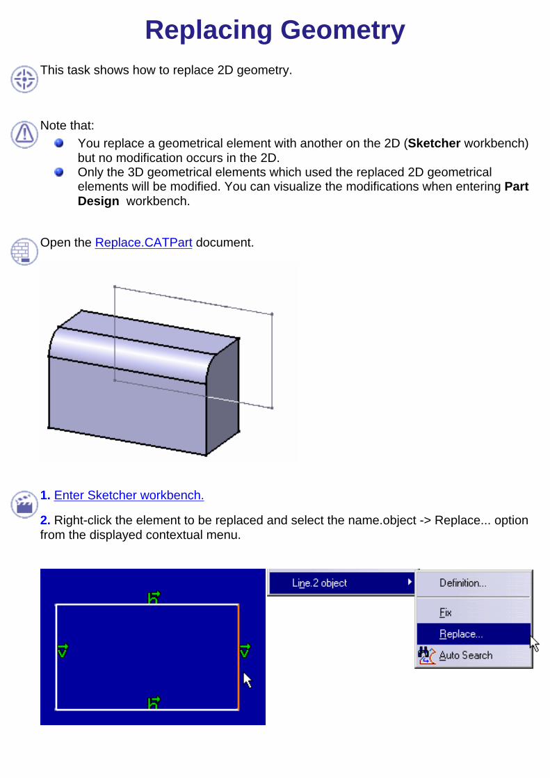
Replacing Geometry
This task shows how to replace 2D geometry.
Note that:You replace a geometrical element with another on the 2D (Sketcher workbench)but no modification occurs in the 2D.Only the 3D geometrical elements which used the replaced 2D geometricalelements will be modified. You can visualize the modifications when entering PartDesign workbench.
Open the Replace.CATPart document.
1. Enter Sketcher workbench.
2. Right-click the element to be replaced and select the name.object -> Replace... optionfrom the displayed contextual menu.

The Replace dialog box appears.
3. Select the element Line2 will be replaced with.
The Replace dialog box now appears as shown here: Line2 will be replaced with Line1.
The geometry is unchanged and appears as shown here:
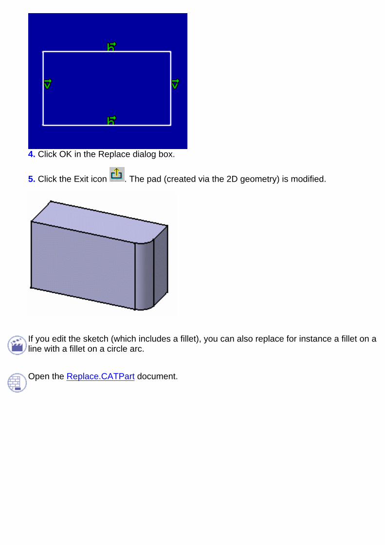
4. Click OK in the Replace dialog box.
5. Click the Exit icon . The pad (created via the 2D geometry) is modified.
If you edit the sketch (which includes a fillet), you can also replace for instance a fillet on aline with a fillet on a circle arc.
Open the Replace.CATPart document.
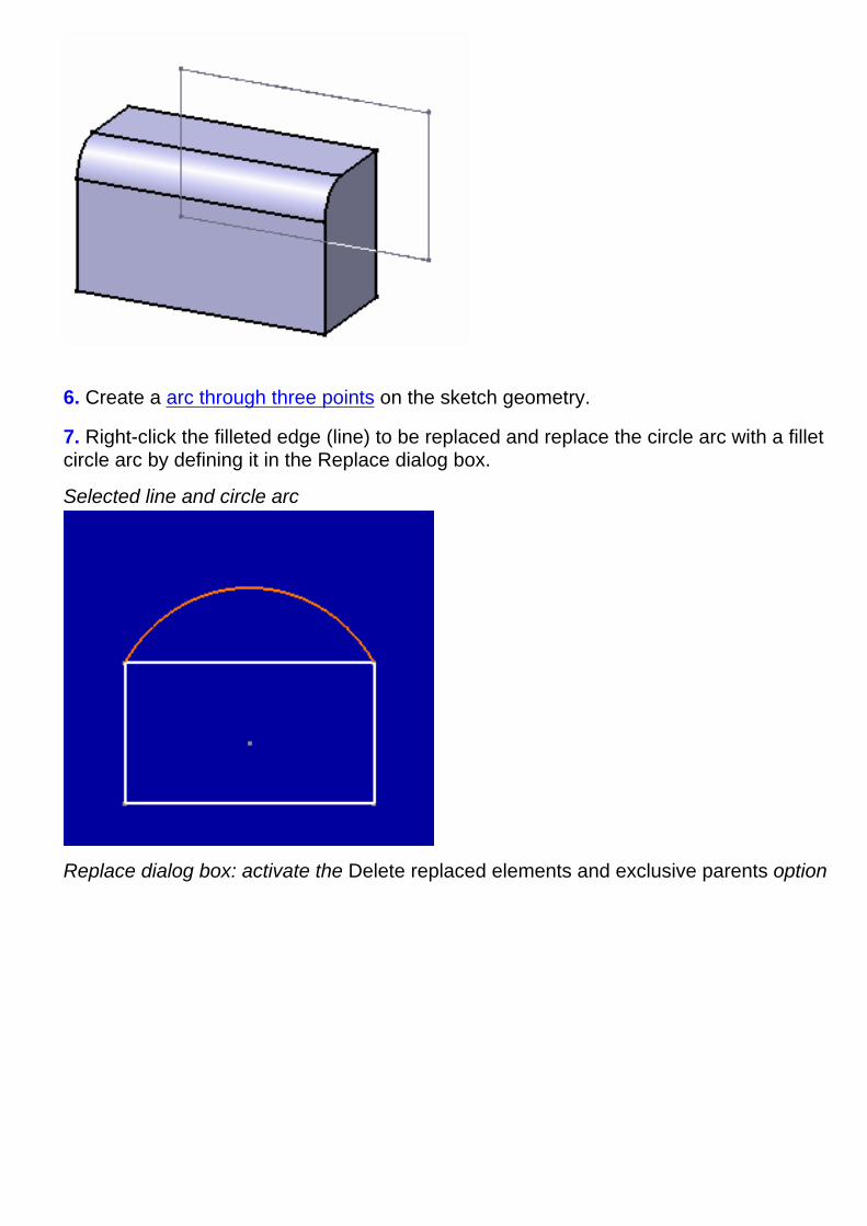
6. Create a arc through three points on the sketch geometry.
7. Right-click the filleted edge (line) to be replaced and replace the circle arc with a filletcircle arc by defining it in the Replace dialog box.
Selected line and circle arc
Replace dialog box: activate the Delete replaced elements and exclusive parents option
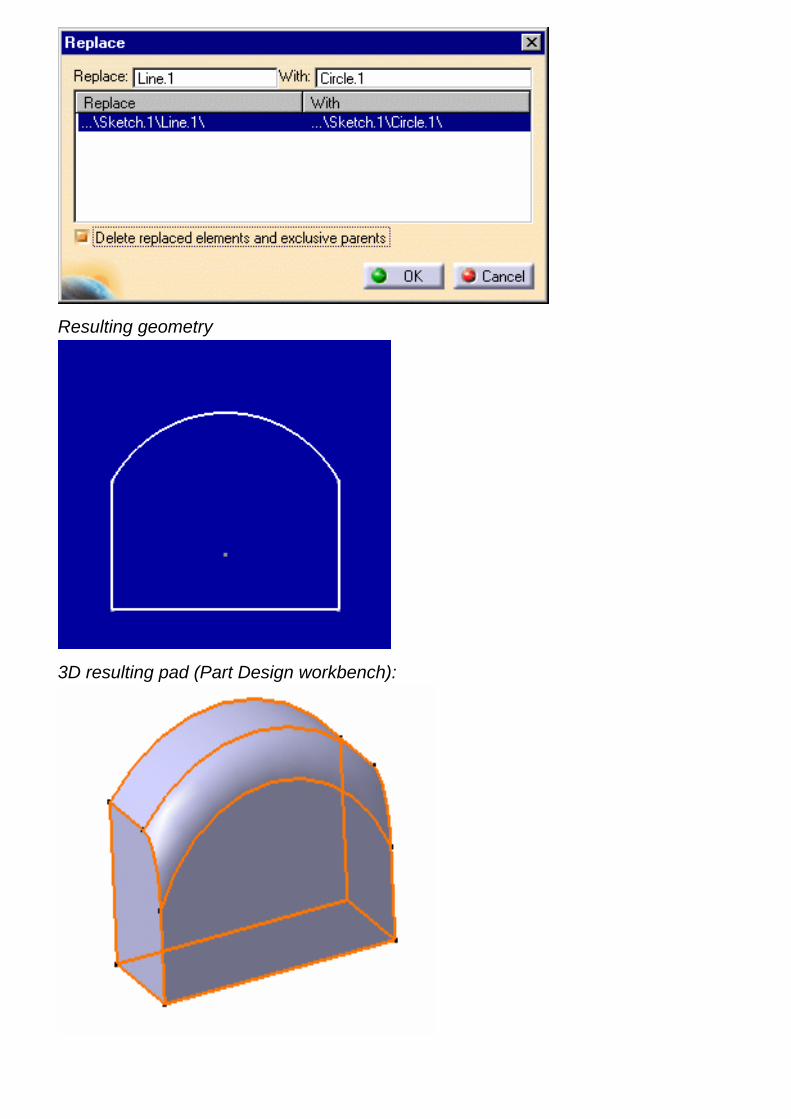
Resulting geometry
3D resulting pad (Part Design workbench):
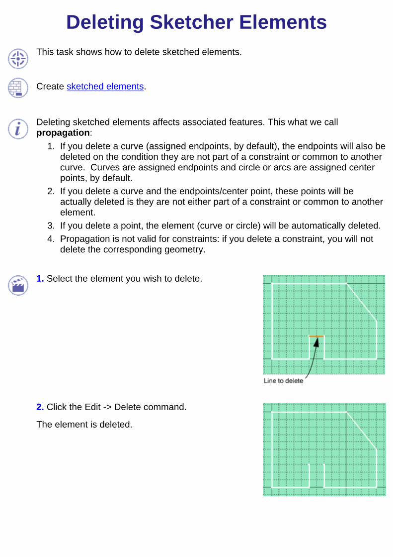
Deleting Sketcher ElementsThis task shows how to delete sketched elements.
Create sketched elements.
Deleting sketched elements affects associated features. This what we callpropagation:
If you delete a curve (assigned endpoints, by default), the endpoints will also bedeleted on the condition they are not part of a constraint or common to anothercurve. Curves are assigned endpoints and circle or arcs are assigned centerpoints, by default.
1.
If you delete a curve and the endpoints/center point, these points will beactually deleted is they are not either part of a constraint or common to anotherelement.
2.
If you delete a point, the element (curve or circle) will be automatically deleted.3. Propagation is not valid for constraints: if you delete a constraint, you will notdelete the corresponding geometry.
4.
1. Select the element you wish to delete.
2. Click the Edit -> Delete command.
The element is deleted.

3. If you wish to delete a set of elements, just multi-select them and apply the Deletecommand.
You can also select the Delete command from the contextual menu. For thisright-click the element to be deleted.In case you created an element using the Tools toolbar, a constraint is appliedto this element. To delete this element, you need to delete the constraint first.To delete constraints, you will follow the same instruction.
You cannot delete elements that are not currently edited sketch elements. This isparticularly true for the reference planes. You can multi-select these elements butthey will not be deleted.

Performing Operations on ProfilesBefore you begin, make sure you are familiar with Tools For Sketching.
The Sketcher workbench provides a set of functionalities for performing operations on profiles. Note that you caneither click on a profile or use the Tools toolbar.
Create cornersCreate a rounded corner (arc tangent to two curves) between two lines using trimming operation.
Create chamfersCreate a chamfer between two lines using trimming operation.
Trim elementsTrim two lines (either one element or all the elements)
Trim multiple elementsTrim a few elements using a curve type element.
Break and trimQuickly delete elements intersected by other Sketcher elements using breaking and trimming operation.
Close elementsClose circles, ellipses or splines using relimiting operation.
Complement an arc (circle or ellipse)Create a complementary arc.
Break elementsBreak a line using a point on the line and then a point that does not belong to the line.
Create symmetrical elementsRepeat existing Sketcher elements using a line, a construction line or an axis.
Translate elementsPerform a translation on 2D elements by defining the duplicate mode and then selecting the element to beduplicated. Multi-selection is not available.
Rotate elementsRotate elements by defining the duplicate mode and then selecting the element to be duplicated.
Scale ElementsScale an entire profile. In other words, you are going to resize a profile to the dimension you specify.
Offset ElementsDuplicate a line, arc or circle type element.
Project 3D elements onto the sketch planeProject edges (elements you select in the Part Design workbench) onto the sketch plane.
Creating Silhouette EdgesCreate silhouette edges to be used in sketches as geometry or reference elements.
Intersect 3D elements with the sketch planeIntersect a face and the sketch plane.
Copy/paste elementsSee how sketched elements behave when copying/pasting elements that were created via projection orintersection.
Isolate projected/intersected elements
Isolate the elements resulting from the use of the Project 3D Elements or Intersect 3D Elementsicons.

Analyze the sketchDisplay a global or individual status on the sketch and correct any problem.
You can sketch pre-defined profiles either via corresponding icons or via the menu bar (Insert/Operation/PredefinedProfiles).
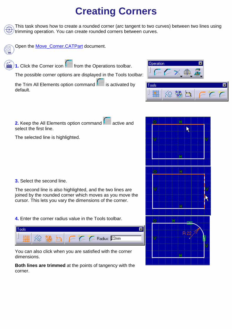
Creating CornersThis task shows how to create a rounded corner (arc tangent to two curves) between two lines usingtrimming operation. You can create rounded corners between curves.
Open the Move_Corner.CATPart document.
1. Click the Corner icon from the Operations toolbar.
The possible corner options are displayed in the Tools toolbar:
the Trim All Elements option command is activated bydefault.
2. Keep the All Elements option command active andselect the first line.
The selected line is highlighted.
3. Select the second line.
The second line is also highlighted, and the two lines arejoined by the rounded corner which moves as you move thecursor. This lets you vary the dimensions of the corner.
4. Enter the corner radius value in the Tools toolbar.
You can also click when you are satisfied with the cornerdimensions.
Both lines are trimmed at the points of tangency with thecorner.
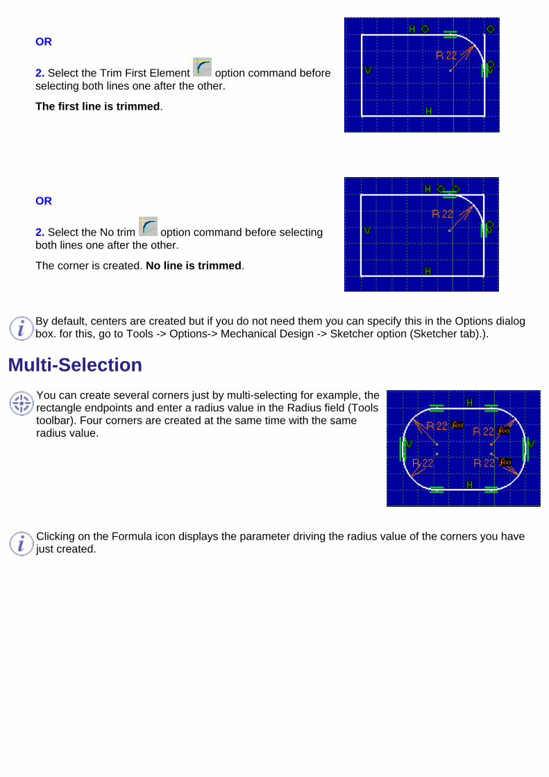
OR
2. Select the Trim First Element option command beforeselecting both lines one after the other.
The first line is trimmed.
OR
2. Select the No trim option command before selectingboth lines one after the other.
The corner is created. No line is trimmed.
By default, centers are created but if you do not need them you can specify this in the Options dialogbox. for this, go to Tools -> Options-> Mechanical Design -> Sketcher option (Sketcher tab).).
Multi-SelectionYou can create several corners just by multi-selecting for example, therectangle endpoints and enter a radius value in the Radius field (Toolstoolbar). Four corners are created at the same time with the sameradius value.
Clicking on the Formula icon displays the parameter driving the radius value of the corners you havejust created.

Creating Chamfers
This task shows how to create a chamfer between two lines trimming either all, the first or none of the elements, and more precisely usingone of the following chamfer definitions:
Angle/HypotenuseLength1/Length2Length1/Angle
You can create chamfers between any type of curves (lines, splines, arcs and so forth). Even if the curves are not consecutive, the chamferwill be created.
Open the Chamfer.CATPart document.
1. Click the Chamfer icon from the Operation toolbar.
The possible chamfer options are displayed in the Tools toolbar.
Trim All / First / No element
Angle-Hypotenuse / Length1-Length2 / Angle-Length1 definition
2. Select the first line.
The selected line is highlighted.3. Select the second line.
The second line is also highlighted, and the two elements are connected by a line representing the chamfer which moves as you move thecursor. This lets you vary the dimensions of the chamfer whose values appear in the Tools toolbar.4. Click when you are satisfied with the dimensions of the chamfer.
The chamfer with both elements trimmed is created.
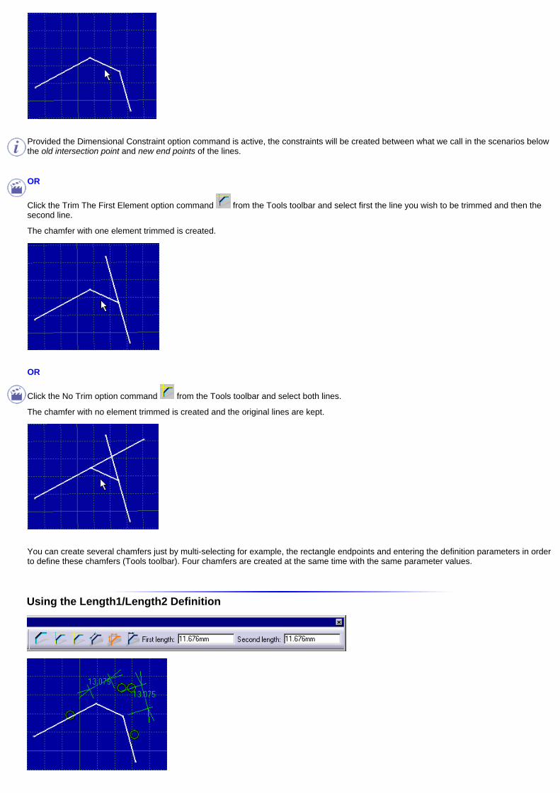
Provided the Dimensional Constraint option command is active, the constraints will be created between what we call in the scenarios belowthe old intersection point and new end points of the lines.
OR
Click the Trim The First Element option command from the Tools toolbar and select first the line you wish to be trimmed and then thesecond line.
The chamfer with one element trimmed is created.
OR
Click the No Trim option command from the Tools toolbar and select both lines.
The chamfer with no element trimmed is created and the original lines are kept.
You can create several chamfers just by multi-selecting for example, the rectangle endpoints and entering the definition parameters in orderto define these chamfers (Tools toolbar). Four chamfers are created at the same time with the same parameter values.
Using the Length1/Length2 Definition

... Between Perpendicular Lines
... Between Non-Perpendicular Lines
... Between Crossing Lines
... Between Non-Intersecting Lines
Note: if the lines are parallels, the extremity points are used to compute the lengths because the virtual intersecting point doesnot exist.
... Between Intersecting Curves
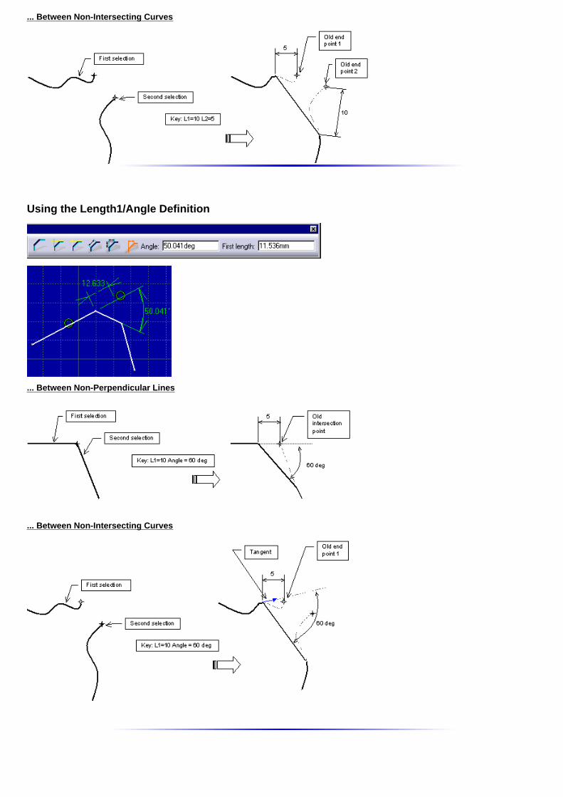
... Between Non-Intersecting Curves
Using the Length1/Angle Definition
... Between Non-Perpendicular Lines
... Between Non-Intersecting Curves

Trimming ElementsThis task shows how to trim two lines (either one element or all the elements). You cancreate rounded corners between consecutive lines, arcs, circles and all types ofcurves.
1. Click the Trim icon from the Operationstoolbar.
The Trim toolbar options display in the Toolstoolbar.
The Trim All option is the command activated bydefault.2. Select the first line.
The selected element is highlighted.
3. Position the cursor on the element to be trimmed.
The second element is highlighted too, and both lines are trimmed.
If you position the cursor on the same first element, it will be trimmed at the location ofthe second position.
The location of the relimitation depends on the location of the cursor.4. Click when you are satisfied with the relimitation of the two lines.
First example Second example
Third example
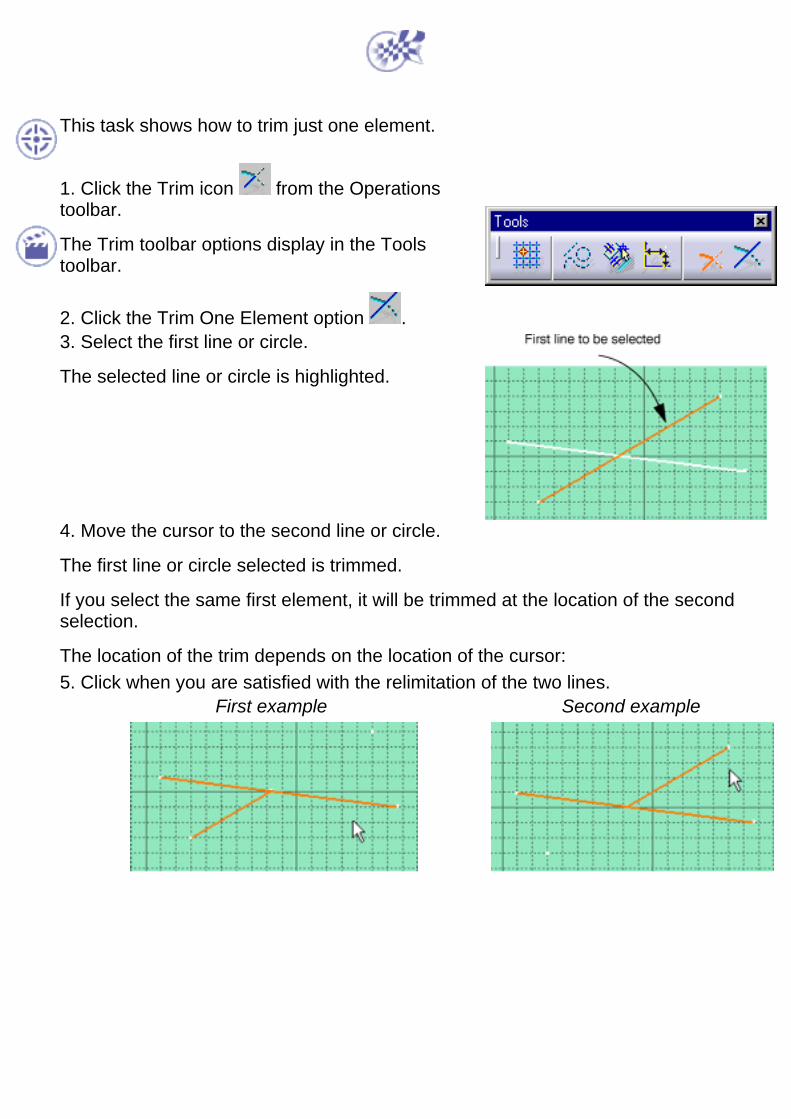
This task shows how to trim just one element.
1. Click the Trim icon from the Operationstoolbar.
The Trim toolbar options display in the Toolstoolbar.
2. Click the Trim One Element option .3. Select the first line or circle.
The selected line or circle is highlighted.
4. Move the cursor to the second line or circle.
The first line or circle selected is trimmed.
If you select the same first element, it will be trimmed at the location of the secondselection.
The location of the trim depends on the location of the cursor:5. Click when you are satisfied with the relimitation of the two lines.
First example Second example
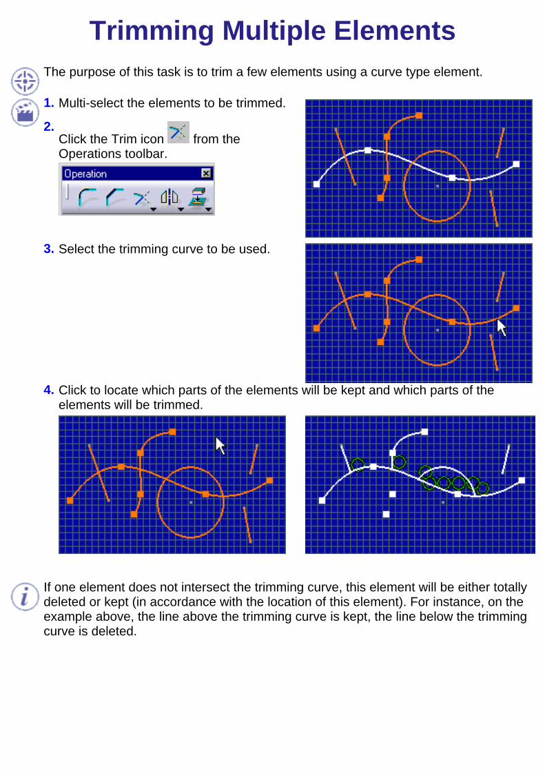
Trimming Multiple ElementsThe purpose of this task is to trim a few elements using a curve type element.
1.
2.
Multi-select the elements to be trimmed.
Click the Trim icon from theOperations toolbar.
3. Select the trimming curve to be used.
4. Click to locate which parts of the elements will be kept and which parts of theelements will be trimmed.
If one element does not intersect the trimming curve, this element will be either totallydeleted or kept (in accordance with the location of this element). For instance, on theexample above, the line above the trimming curve is kept, the line below the trimmingcurve is deleted.
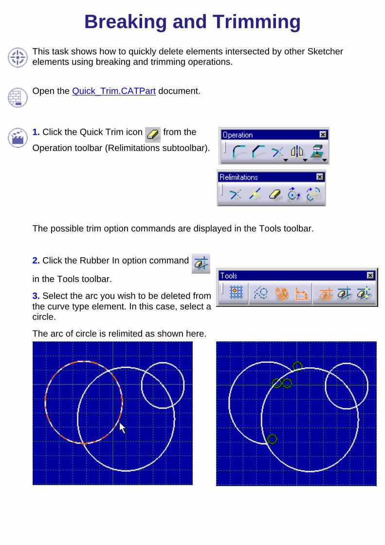
Breaking and Trimming
This task shows how to quickly delete elements intersected by other Sketcherelements using breaking and trimming operations.
Open the Quick_Trim.CATPart document.
1. Click the Quick Trim icon from the
Operation toolbar (Relimitations subtoolbar).
The possible trim option commands are displayed in the Tools toolbar.
2. Click the Rubber In option command
in the Tools toolbar.
3. Select the arc you wish to be deleted fromthe curve type element. In this case, select acircle.
The arc of circle is relimited as shown here.
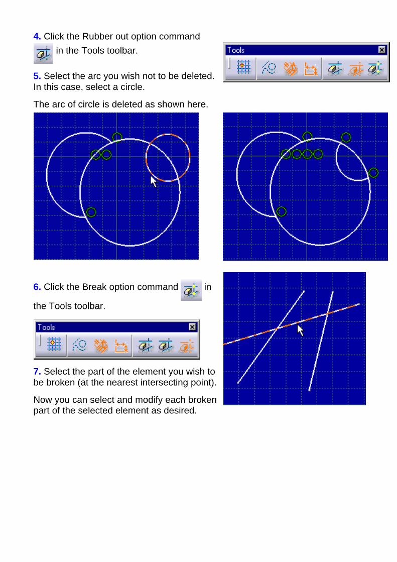
4. Click the Rubber out option command in the Tools toolbar.
5. Select the arc you wish not to be deleted. In this case, select a circle.
The arc of circle is deleted as shown here.
6. Click the Break option command in
the Tools toolbar.
7. Select the part of the element you wish tobe broken (at the nearest intersecting point).
Now you can select and modify each brokenpart of the selected element as desired.

If you need to delete several elements, you can double-click the icon and delete theelements one after the other.
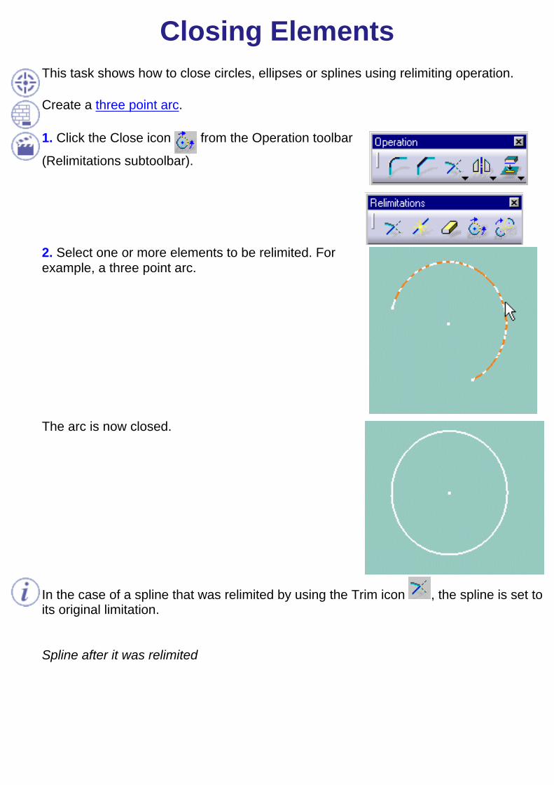
Closing ElementsThis task shows how to close circles, ellipses or splines using relimiting operation.
Create a three point arc.
1. Click the Close icon from the Operation toolbar
(Relimitations subtoolbar).
2. Select one or more elements to be relimited. Forexample, a three point arc.
The arc is now closed.
In the case of a spline that was relimited by using the Trim icon , the spline is set toits original limitation.
Spline after it was relimited
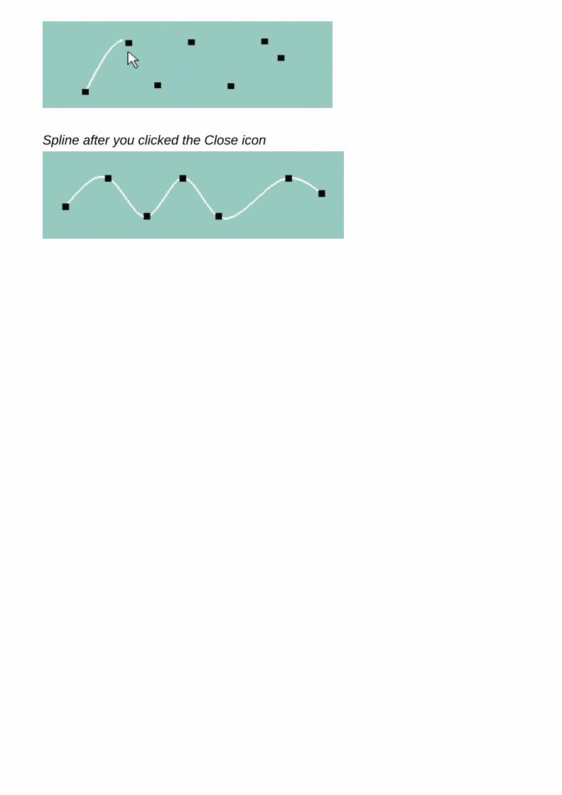
Spline after you clicked the Close icon
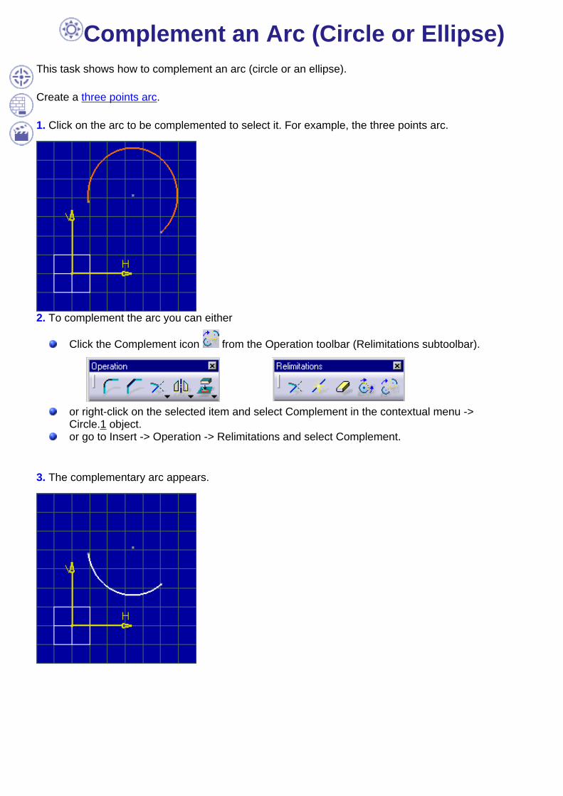
Complement an Arc (Circle or Ellipse)This task shows how to complement an arc (circle or an ellipse).
Create a three points arc.
1. Click on the arc to be complemented to select it. For example, the three points arc.
2. To complement the arc you can either
Click the Complement icon from the Operation toolbar (Relimitations subtoolbar).
or right-click on the selected item and select Complement in the contextual menu ->Circle.1 object.or go to Insert -> Operation -> Relimitations and select Complement.
3. The complementary arc appears.
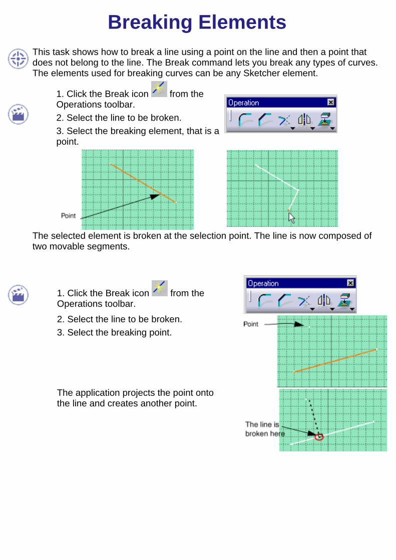
Breaking ElementsThis task shows how to break a line using a point on the line and then a point thatdoes not belong to the line. The Break command lets you break any types of curves.The elements used for breaking curves can be any Sketcher element.
1. Click the Break icon from theOperations toolbar.2. Select the line to be broken.3. Select the breaking element, that is apoint.
The selected element is broken at the selection point. The line is now composed oftwo movable segments.
1. Click the Break icon from theOperations toolbar.2. Select the line to be broken.3. Select the breaking point.
The application projects the point ontothe line and creates another point.
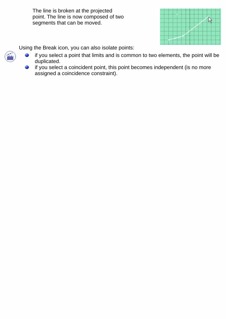
The line is broken at the projectedpoint. The line is now composed of twosegments that can be moved.
Using the Break icon, you can also isolate points:if you select a point that limits and is common to two elements, the point will beduplicated.if you select a coincident point, this point becomes independent (is no moreassigned a coincidence constraint).

Creating Symmetrical ElementsThis task shows you how to repeat existing Sketcher elements using a line, aconstruction line or an axis. In this particular case, we will duplicate a circle.
1. Select the circle to be duplicated by symmetry.
2. Click the Symmetry icon from the Operationstoolbar.
3. Select the axis you previously created.
The selected circle is duplicated and a symmetryconstraint is created on the condition you previously
activated the Dimensional Constraint option fromthe Tools toolbar.
You can also use multi-selection. Drag the cursor andcreate a trap. Then select the symmetry axis.

Translating ElementsThis task will show you how to perform a translation on 2D elements by defining theduplicate mode and then selecting the element to be duplicated. Multi-selection is notavailable.
The application provides a powerful command for translating elements. You mayeither perform a simple translation (by moving elements) or create several copiesof 2D elements.
Translating elements also means re-computing distance, angle and/or lengthconstraint values, if needed. Be careful: only non-fixed elements are updated.
Open the Transform_replace01.CATPart document.
1. Click the Translation icon from theOperation toolbar (Transformationsubtoolbar).
The Translation Definition dialog boxdisplays and will remain displayed all alongyour translation creation.
2. Enter the number of copies you need.The duplicate mode is activated by default.
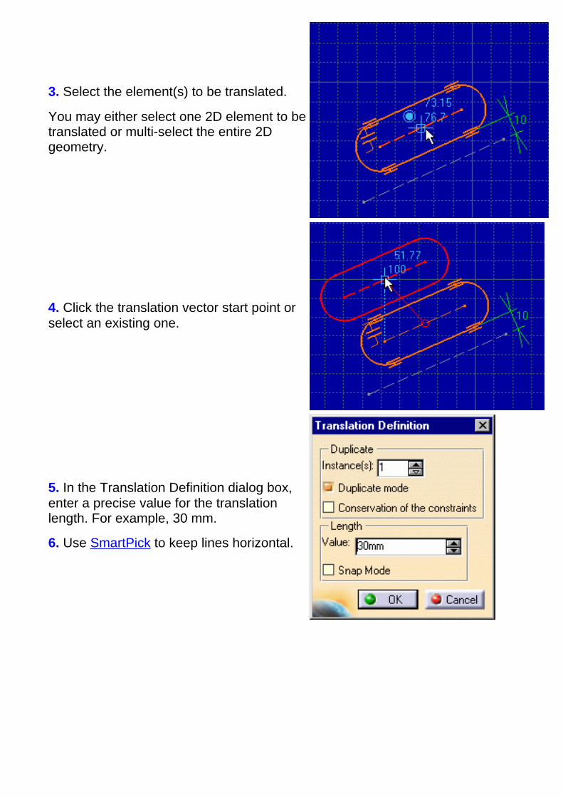
3. Select the element(s) to be translated.
You may either select one 2D element to betranslated or multi-select the entire 2Dgeometry.
4. Click the translation vector start point orselect an existing one.
5. In the Translation Definition dialog box,enter a precise value for the translationlength. For example, 30 mm.
6. Use SmartPick to keep lines horizontal.

7. Click OK in the Translation Definitiondialog box to end the translation.
8. The last translation is always highlighted.You may restart from this one if you needmore copies.
The Undo command is available from the toolbar, while you are translatingelements.
Note that:Internal constraints are preserved External constraints:
geometrical constraints are preserveddimensional constraints are preserved but revalued.

Rotating Elements
This task will show you how to rotate elements by defining the duplicate mode andthen selecting the element to be duplicated.
In this scenario, the geometry is simply moved. But note that, you can also duplicateelements with the Rotation command.
Rotating elements also means re-computing distance values into angle values, ifneeded. Be careful: only non-fixed elements are updated.
Open the Transform_replace01.CATPart document.
1. Click the Rotation icon from theOperations toolbar (Transformation subtoolbar).
The Rotation Definition dialog box appears andwill remain displayed all along the rotation.
2. De-activate the Duplicate mode, if needed.
If you keep it active, you will be allowed todefine the number of the instances you wish tocreate in the meantime.

3. Select the geometry to be rotated. Here,multi-select the entire profile.
4. Select or click the rotation center point.You can also enter a value in the fields displayed (Tools toolbar).
5. Select or click a point to define the reference line that will be used for computingthe angle.
6. Select or click a point to define an angle.You can also enter a value for the rotationangle in the Rotation Definition dialog box
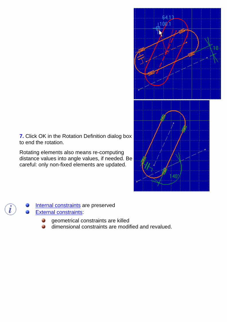
7. Click OK in the Rotation Definition dialog boxto end the rotation.
Rotating elements also means re-computingdistance values into angle values, if needed. Becareful: only non-fixed elements are updated.
Internal constraints are preserved External constraints:
geometrical constraints are killeddimensional constraints are modified and revalued.
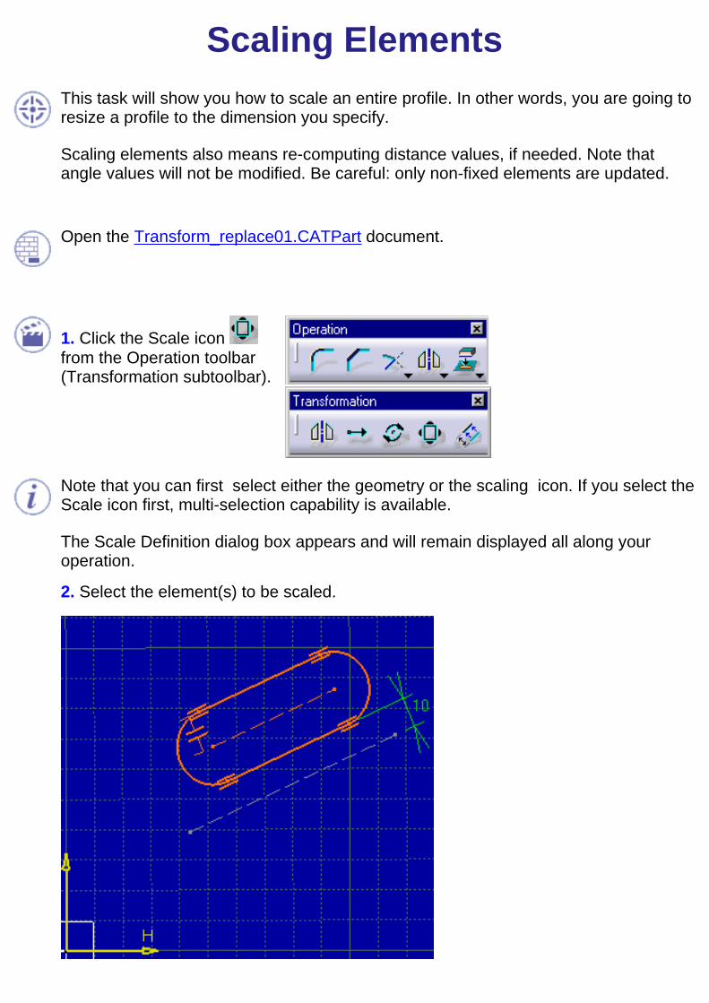
Scaling ElementsThis task will show you how to scale an entire profile. In other words, you are going toresize a profile to the dimension you specify.
Scaling elements also means re-computing distance values, if needed. Note thatangle values will not be modified. Be careful: only non-fixed elements are updated.
Open the Transform_replace01.CATPart document.
1. Click the Scale icon from the Operation toolbar(Transformation subtoolbar).
Note that you can first select either the geometry or the scaling icon. If you select theScale icon first, multi-selection capability is available.
The Scale Definition dialog box appears and will remain displayed all along youroperation.
2. Select the element(s) to be scaled.
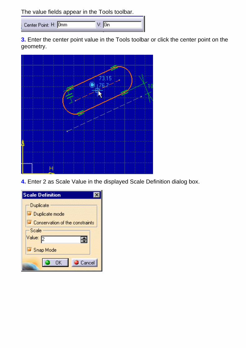
The value fields appear in the Tools toolbar.
3. Enter the center point value in the Tools toolbar or click the center point on thegeometry.
4. Enter 2 as Scale Value in the displayed Scale Definition dialog box.
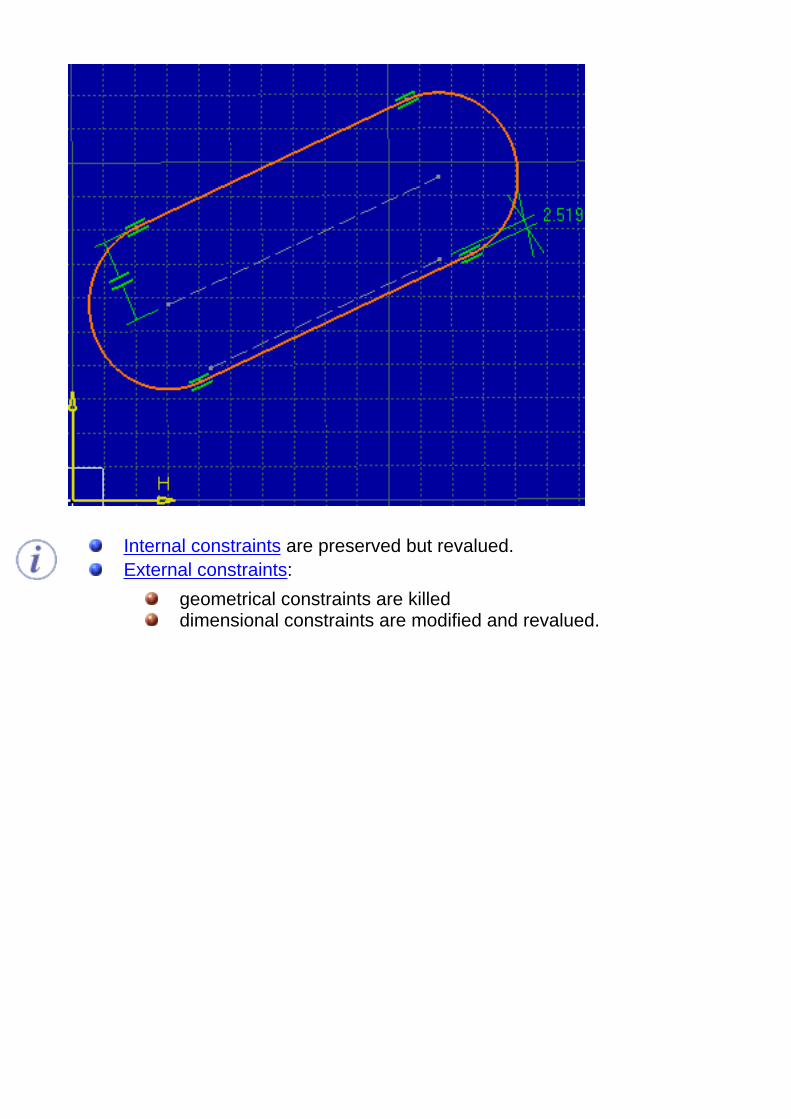
Internal constraints are preserved but revalued.External constraints:
geometrical constraints are killeddimensional constraints are modified and revalued.
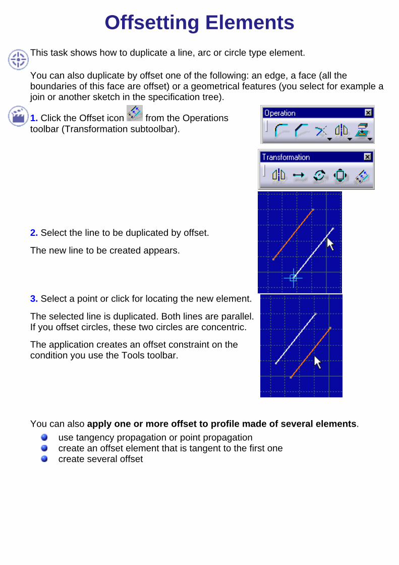
Offsetting ElementsThis task shows how to duplicate a line, arc or circle type element.
You can also duplicate by offset one of the following: an edge, a face (all theboundaries of this face are offset) or a geometrical features (you select for example ajoin or another sketch in the specification tree).
1. Click the Offset icon from the Operationstoolbar (Transformation subtoolbar).
2. Select the line to be duplicated by offset.
The new line to be created appears.
3. Select a point or click for locating the new element.
The selected line is duplicated. Both lines are parallel.If you offset circles, these two circles are concentric.
The application creates an offset constraint on thecondition you use the Tools toolbar.
You can also apply one or more offset to profile made of several elements.
use tangency propagation or point propagation create an offset element that is tangent to the first onecreate several offset
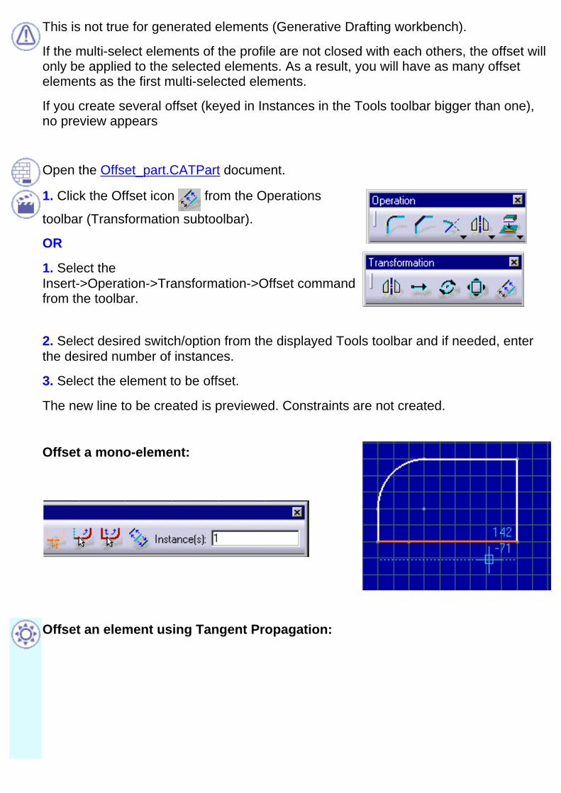
This is not true for generated elements (Generative Drafting workbench).
If the multi-select elements of the profile are not closed with each others, the offset willonly be applied to the selected elements. As a result, you will have as many offsetelements as the first multi-selected elements.
If you create several offset (keyed in Instances in the Tools toolbar bigger than one),no preview appears
Open the Offset_part.CATPart document.
1. Click the Offset icon from the Operations
toolbar (Transformation subtoolbar).
OR
1. Select theInsert->Operation->Transformation->Offset commandfrom the toolbar.
2. Select desired switch/option from the displayed Tools toolbar and if needed, enterthe desired number of instances.
3. Select the element to be offset.
The new line to be created is previewed. Constraints are not created.
Offset a mono-element:
Offset an element using Tangent Propagation:

Offset an element using Point Propagation:
Offset an element symmetrically to another:
Offset and duplicate multiple elements:
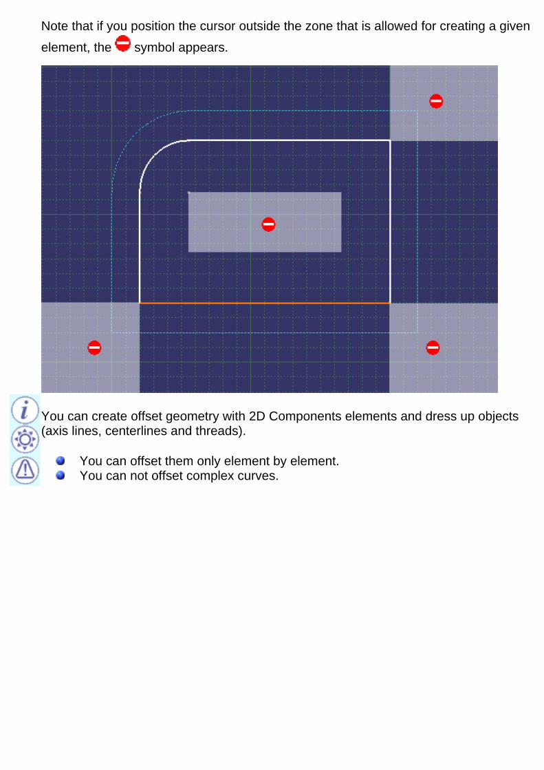
Note that if you position the cursor outside the zone that is allowed for creating a givenelement, the symbol appears.
You can create offset geometry with 2D Components elements and dress up objects(axis lines, centerlines and threads).
You can offset them only element by element.You can not offset complex curves.
Projecting 3D Elements onto the SketchPlane
This task shows how to project edges (elements you select in the Part Designworkbench) onto the sketch plane.
1. Click the Project 3D Elements icon from the Operations toolbar (3D Geometrysubtoolbar).
2. Multi-select the edges you wish to project onto the sketch plane.
The edges are projected onto the sketch plane. These projections are yellow (inothers words, you cannot move them).
You can apply the Relimitation , Corner and Chamfer commands onprojections.If you select a face, the edges areprojected.

When the generated elements have the same geometrical support and thereforeassociative , they are created as marks and yellow colored. You cannot move ormodify them. Otherwise (not the same geometrical support and therefore notassociative), they are created as single curves.

Creating Silhouette EdgesThis task shows how to create silhouette edges to be used in sketches as geometry orreference elements.
Limitations are same as Projection/Intersection command, as far as associativity isconcerned.
You can only create a silhouette edge from a canonical surface whose axis is parallelto the Sketch plane.
Open the Silhouette_Edge.CATPartdocument.
1. Select Plane1 and go into Sketcher workbench.
2. Click the 3D Silhouette Edges icon
from the Operation toolbar (3D Geometrysubtoolbar).
3. Select the canonical surface.
The silhouette edges are created onto the sketch plane. These silhouette edges areyellow if they are associative with the 3D. You cannot move or modify them but youcan delete one of them which means deleting one trace independently from the other.

You can select one of the two intersectionsand set it into the Construction mode:
You can create geometry and constraintsusing this intersection:
You can re-limit this created silhouetteedgeusing the geometry:

The silhouette command generated one or two marks (edges) if one mark is made ofmore that one curves. If those curves do not have the same geometrical support, theresulting silhouette edges will not be associative (as for Projection/Intersectioncommands).
Intersecting 3D Elements with theSketch Plane
This task shows how to intersect a face and the sketch plane.
Open the Intersection_Canonic.CATPart document.
1. Select the face of interest.
2. Click the Intersect 3D Elements icon fromthe Operations toolbar (3D Geometry subtoolbar).
The software computes and displays the intersection between the face and the sketchplane. The intersection is yellow (in others words, you cannot move it).
You can apply the Trim , Corner and Chamfer commands onintersections.
When the generated elements have the same geometrical support and are thereforeassociative , they are created as marks and yellow colored. You cannot move ormodify them. Otherwise (not the same geometrical support and therefore notassociative), they are created as single curves.This is not the case when you intersect a canonical surface. In this case, you maygenerate one or two marks. If one of these mark is made of more than one curve, thismark will only be associative if they have the same geometrical support.
Open the Intersection_Canonic.CATPart document.

Copying/Pasting Projected/IntersectedElements
This task shows how sketched elements behave when copying/pasting elements thatwere created via projection or intersection. For general information on copy/paste, seeInfrastructure User's guide.
1. Perform copy/paste operation. External references are deleted:
Constraints on external geometry are deleted.Projections/Intersections are isolated: each trace is replaced with an equivalentgeometrical element. Projection/intersection cannot be performed any more.There is no associativity either.
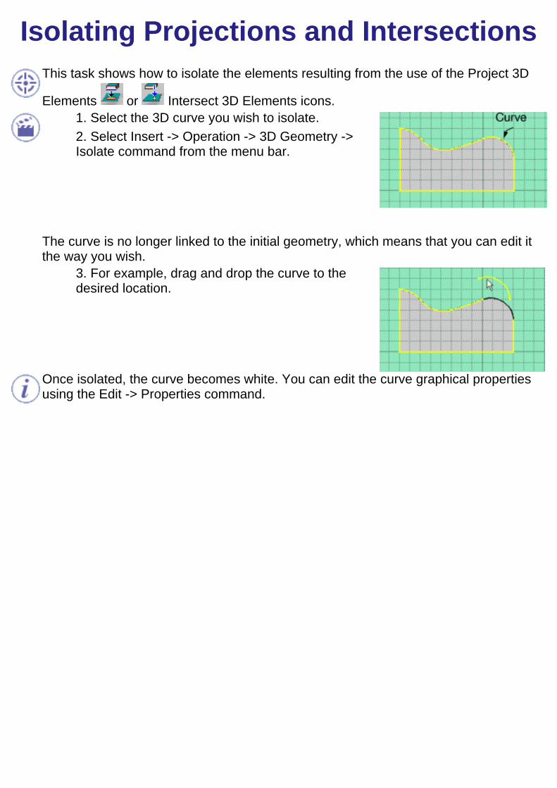
Isolating Projections and IntersectionsThis task shows how to isolate the elements resulting from the use of the Project 3D
Elements or Intersect 3D Elements icons.1. Select the 3D curve you wish to isolate.2. Select Insert -> Operation -> 3D Geometry ->Isolate command from the menu bar.
The curve is no longer linked to the initial geometry, which means that you can edit itthe way you wish.
3. For example, drag and drop the curve to thedesired location.
Once isolated, the curve becomes white. You can edit the curve graphical propertiesusing the Edit -> Properties command.
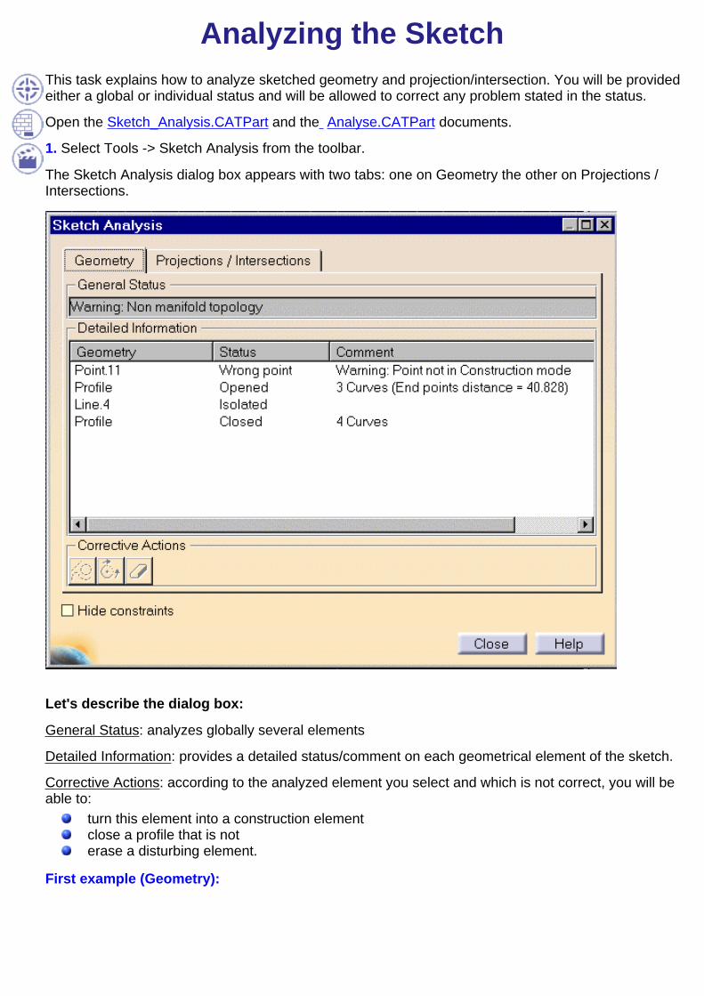
Analyzing the SketchThis task explains how to analyze sketched geometry and projection/intersection. You will be providedeither a global or individual status and will be allowed to correct any problem stated in the status.
Open the Sketch_Analysis.CATPart and the Analyse.CATPart documents.
1. Select Tools -> Sketch Analysis from the toolbar.
The Sketch Analysis dialog box appears with two tabs: one on Geometry the other on Projections /Intersections.
Let's describe the dialog box:
General Status: analyzes globally several elements
Detailed Information: provides a detailed status/comment on each geometrical element of the sketch.
Corrective Actions: according to the analyzed element you select and which is not correct, you will beable to:
turn this element into a construction elementclose a profile that is noterase a disturbing element.
First example (Geometry):

In the case above, you will select the Construction mode option for turning the standard mode point intoa construction mode point.
Second example (Projections / Intersections):
If you click on Sketch2 (specification tree) and then select the Projections / Intersections tab, thefollowing analysis is possibly performed:

Let's describe the dialog box:
Detailed Information: provides a detailed status/comment on each projection or intersection, onconstraints and so forth.
Corrective Actions: according to the analyzed element you select and which is not correct, you will beable to:
isolate geometryactivate/deactivate a constrainterase geometryreplace 3D geometry

Before You Begin
What is SmartPick?
SmartPick is an intuitive, easy-to-use tool designed to make all your Sketcher creation and editiontasks as simple as possible.
SmartPick dynamically detects the following geometrical constraints:support lines and circlesalignmentparallelismperpendicularitytangencyconcentricityhorizontalityverticalitymidpoint
What are Constraints?
There are times when simple sketches are adequate for your design process, but you will oftenneed to work on more complex sketches requiring a rich set of geometrical or dimensionalconstraints. The Sketcher workbench provides constraint commands which will allow you to fullysketch your profiles.
Geometrical Constraints
A geometrical constraint is a relationship that forces a limitation between one or more geometricelements. For example, a geometrical constraint might require that two lines be parallel. If youselect three lines, or two lines and a point, these elements will automatically result parallel to eachothers, as illustrated in the table further down.
You can set a constraint on one element or between two or more elements.
Number of Elements CorrespondingGeometrical Constraints
One Element
FixHorizontalVertical

Two Elements
CoincidenceConcentricityTangencyParallelismMidpointPerpendicularity
Three Elements SymmetryEquidistant Point
When creating your constraint, remember that a green constraint is a valid constraint by default.Conversely, a yellow constraint indicates that the definition is not valid. The software lets youcustomize the colors and more generally the style of the constraints you use. To have detailsabout these capabilities, see Infrastructure User's guide.
When you position the cursor on constraint symbols, the software calls your attention on theelements involved in the constraint system. Here are two examples of what you may get.
Dimensional Constraints
A dimensional constraint is a constraint which value determines geometric object measurement.For example, it might control the length of a line, or the distance between two points.
You will use the Constraint command to finalize your profile. The Constraint command allowsyou setting dimensional or geometrical constraints but you will mainly use it to set dimensionalconstraints.
You can combine dimensional constraints to constrain a feature or sketch.
You can set a dimensional constraint on one element or between two elements.
Number ofElements
Corresponding DimensionalConstraints
One Element
LengthRadius/DiameterSemimajor axisSemiminor axis
Two ElementsDistance
Angle
You can apply a diameter constraint betweentwo lines provided one of these lines is an axisline.
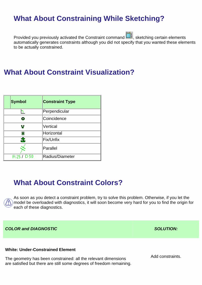
What About Constraining While Sketching?
Provided you previously activated the Constraint command , sketching certain elementsautomatically generates constraints although you did not specify that you wanted these elementsto be actually constrained.
What About Constraint Visualization?
Symbol Constraint Type
Perpendicular
Coincidence
VerticalHorizontalFix/Unfix
Parallel
/ Radius/Diameter
What About Constraint Colors?
As soon as you detect a constraint problem, try to solve this problem. Otherwise, if you let themodel be overloaded with diagnostics, it will soon become very hard for you to find the origin foreach of these diagnostics.
COLOR and DIAGNOSTIC SOLUTION:
White: Under-Constrained Element
The geometry has been constrained: all the relevant dimensionsare satisfied but there are still some degrees of freedom remaining.
Add constraints.

Brown: Element Not Changed
Some geometrical elements are over-defined or not-consistent. Asa result, geometry that depend(s) on the problematic area will notbe recalculated.
Remove one or more dimensionalconstraints.
Green: Fixed Element
The geometry has been fixed using the Constraint Definition dialogbox or the contextual menu (right mouse button).

Green: Iso-Constrained Element
All the relevant dimensions are satisfied. The geometry is fixed andcannot be moved from its geometrical support.
Geometry before and after being moved:
Purple: Over-Constrained Element
The dimensioning scheme is overconstrained: too manydimensions were applied to the geometry.
Remove one or more dimensionalconstraints.
Red: Inconsistent Element
At least one dimension value needs to be changed. This is also thecase when elements are underconstrained and the systemproposes defaults that do not lead to a solution.
Add dimensions. Set dimensionvalue(s) properly.

Creating a Constraint Between a 2D and a 3D ElementWhen you need to create a constraint between a 3D element and a line, for example, this creation mayresult impossible. This is the case when the projection or intersection resulting use-edge does not givea unique solution. In other words, the use-edge (projection of one side of a pad) corresponds to severallimit edges of the side.
As a result, you will not be able to select this 3D element when creating the constraint. You willtherefore have to use manually the projection operators.
Inconsistent and Over-Constrained Elements:When leaving the sketcher, the software will only generate a warning for inconsistent and over-constrained elements if they belong to asketch issued from the release 5 or releases before. Since release 6, the software generates an error.
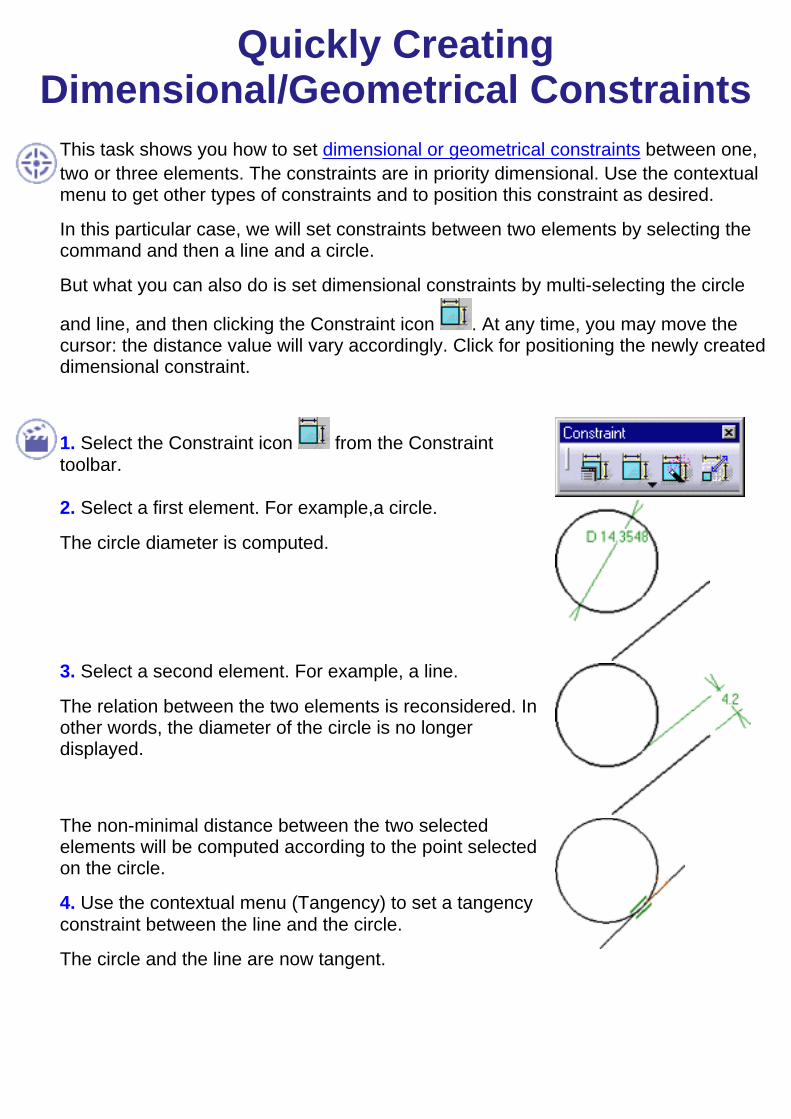
Quickly CreatingDimensional/Geometrical Constraints
This task shows you how to set dimensional or geometrical constraints between one,two or three elements. The constraints are in priority dimensional. Use the contextualmenu to get other types of constraints and to position this constraint as desired.
In this particular case, we will set constraints between two elements by selecting thecommand and then a line and a circle.
But what you can also do is set dimensional constraints by multi-selecting the circle
and line, and then clicking the Constraint icon . At any time, you may move thecursor: the distance value will vary accordingly. Click for positioning the newly createddimensional constraint.
1. Select the Constraint icon from the Constrainttoolbar.
2. Select a first element. For example,a circle.
The circle diameter is computed.
3. Select a second element. For example, a line.
The relation between the two elements is reconsidered. Inother words, the diameter of the circle is no longerdisplayed.
The non-minimal distance between the two selectedelements will be computed according to the point selectedon the circle.
4. Use the contextual menu (Tangency) to set a tangencyconstraint between the line and the circle.
The circle and the line are now tangent.

5. Select the Constraint icon .
6. Select the line and click the Fix contextual command toprevent the line from moving.
The line is fixed and the anchor, that is the fix symbol,appears.
To unfix the line, you can use the Unfix contextual menuitem.
The Shift key key allows deactivating a constraint (auto-detected via SmartPick).
The Ctrl key key allows locking the constraint currently created and creating others.
selecting one element allows creating a dimensional constraintselecting two elements allows creating a distance or an angle constraintIf you want to create a symmetry or equidistance constraints on three elementsyou must select Allow symmetry line in the contextual menu after havingselected the two first elements.
You can also define constraints using the Constraint Definition dialog box, the command, or by means of the contextual command (right-click).
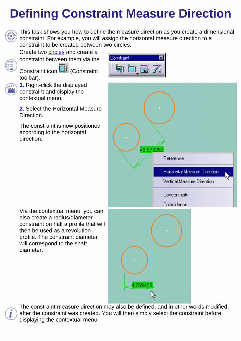
Defining Constraint Measure DirectionThis task shows you how to define the measure direction as you create a dimensionalconstraint. For example, you will assign the horizontal measure direction to aconstraint to be created between two circles.Create two circles and create aconstraint between them via the
Constraint icon (Constrainttoolbar).1. Right-click the displayedconstraint and display thecontextual menu.
2. Select the Horizontal MeasureDirection.
The constraint is now positionedaccording to the horizontaldirection.
Via the contextual menu, you canalso create a radius/diameterconstraint on half a profile that willthen be used as a revolutionprofile. The constraint diameterwill correspond to the shaftdiameter.
The constraint measure direction may also be defined, and in other words modified,after the constraint was created. You will then simply select the constraint beforedisplaying the contextual menu.
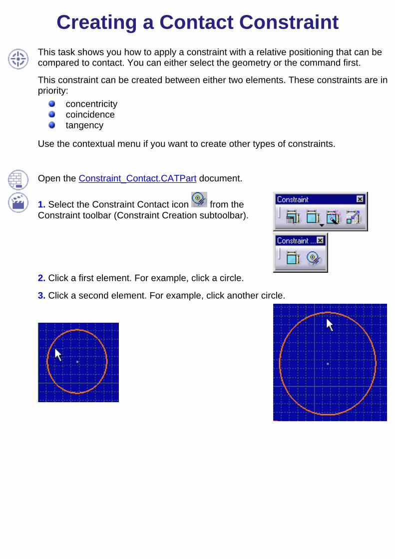
Creating a Contact ConstraintThis task shows you how to apply a constraint with a relative positioning that can becompared to contact. You can either select the geometry or the command first.
This constraint can be created between either two elements. These constraints are inpriority:
concentricitycoincidencetangency
Use the contextual menu if you want to create other types of constraints.
Open the Constraint_Contact.CATPart document.
1. Select the Constraint Contact icon from theConstraint toolbar (Constraint Creation subtoolbar).
2. Click a first element. For example, click a circle.
3. Click a second element. For example, click another circle.
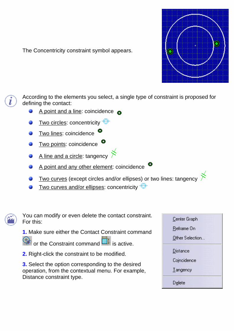
The Concentricity constraint symbol appears.
According to the elements you select, a single type of constraint is proposed fordefining the contact:
A point and a line: coincidence
Two circles: concentricity
Two lines: coincidence
Two points: coincidence
A line and a circle: tangency
A point and any other element: coincidence
Two curves (except circles and/or ellipses) or two lines: tangency Two curves and/or ellipses: concentricity
You can modify or even delete the contact constraint.For this:
1. Make sure either the Contact Constraint command
or the Constraint command is active.
2. Right-click the constraint to be modified.
3. Select the option corresponding to the desiredoperation, from the contextual menu. For example,Distance constraint type.
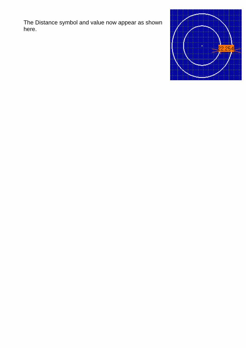
The Distance symbol and value now appear as shownhere.

Modifying Constraint DefinitionThis task shows you how to edit constraints defined in the Sketcher or in the 3D area.
Open the Constraint_Definition.CATPart document and double-click Sketch1 in the specification tree.
1. If needed, double-click the sketch to be edited.
You are now in the Sketcher.
2. Double-click the constraint you wish to edit. In this example,double-click the radius value, that is 35.
You could also use the ConstraintDYS.object -> Definition...contextual menu item.
The Constraint Edition dialog box is displayed.
3. Check the Reference option to make the constraint a reference.The Radius field is deactivated, indicating that the value is nowdriven by modifications to the sketch.
The radius value is displayed in brackets in the geometry area.
If you drag the corner, you can check that the radius value is updated.
4. Double-click the angle value, that is 110. In the dialog box thatappears, enter 125 and click OK.
The new value is displayed in the geometry area. It affects theangle. The sketch shape is also modified due to the radius previouslyconverted into a measure.
5. Now, double-click the offset value between the bottom construction line and the profile bottom line.
6. The Constraint Edition dialog box is displayed. Click the More button to access additional information.
Reference: when un-checked, means that the constraint is driving.
7. Click Line5. Line 5 is highlighted in the geometry area.
8. Click Reconnect to redefine the offset constraint. You are going to choose a new reference.
You can reconnect constraints by means of elements such as planes, edges and so forth.
9. Select Line6, that is the other construction line in the geometry andenter 50 in the Value field.
10. Click OK to apply the modification.
The position of the profile is modified.

11. Quit the Sketcher.
The application has integrated the modifications to the sketch. Thevalue of the 3D measured constraint is updated.
12. Double-click the value of the offset constraint, that is 50.
The Constraint Edition dialog box is displayed.
13. Enter 30 mm in the Value field.
14. Click OK to edit the offset.
In the 3D area, if you select the blue pad, the Edit Parameterscontextual command allows you to display all parameters andconstraints defined for that pad.
When you are in the Repeat mode (you double-clicked on the command for creating a constraint), if you try to edit an existingconstraint while creating another constraint, the edition modification will only be taken into account when you have finishedcreating this other constraint.
About Diameter and Radius ConstraintsYou can obtain a radius constraint by editing a diameter constraint. You just need to double-click the diameter constraint andchoose the radius option in the dialog box that appears.
If you need to create a formula remember that:
- the parameter corresponding to the radius or diameter constraint is referred to as "RadiusX.object"
- this parameter always contains the radius value.
For more information about formulas, refer to Knowledge Advisor User's Guide.
Deactivating or Activating ConstraintsYou can deactivate a constraint by right-clicking it and selecting the XXX.N.object -> Deactivate option from the contextual menu. Inother words, this constraint will still appear on the sketch but will not behave as such.
Deactivated constraints appear preceded by red brackets ( ).
Conversely, to activate a constraint, use the Activate option from the contextual menu.
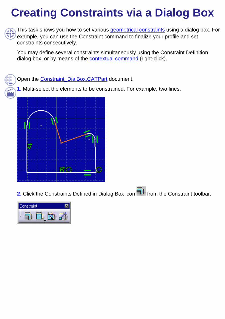
Creating Constraints via a Dialog BoxThis task shows you how to set various geometrical constraints using a dialog box. Forexample, you can use the Constraint command to finalize your profile and setconstraints consecutively.
You may define several constraints simultaneously using the Constraint Definitiondialog box, or by means of the contextual command (right-click).
Open the Constraint_DialBox.CATPart document.
1. Multi-select the elements to be constrained. For example, two lines.
2. Click the Constraints Defined in Dialog Box icon from the Constraint toolbar.
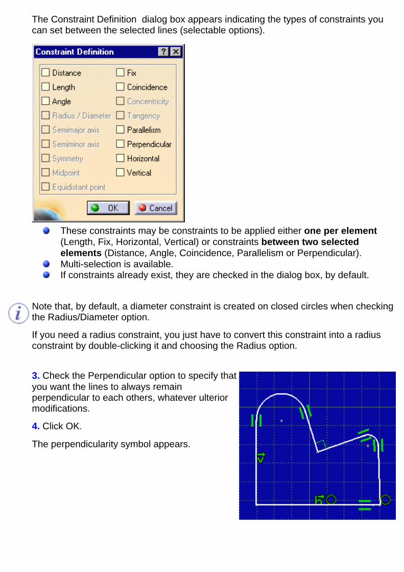
The Constraint Definition dialog box appears indicating the types of constraints youcan set between the selected lines (selectable options).
These constraints may be constraints to be applied either one per element(Length, Fix, Horizontal, Vertical) or constraints between two selectedelements (Distance, Angle, Coincidence, Parallelism or Perpendicular).Multi-selection is available.If constraints already exist, they are checked in the dialog box, by default.
Note that, by default, a diameter constraint is created on closed circles when checkingthe Radius/Diameter option.
If you need a radius constraint, you just have to convert this constraint into a radiusconstraint by double-clicking it and choosing the Radius option.
3. Check the Perpendicular option to specify thatyou want the lines to always remainperpendicular to each others, whatever ulteriormodifications.
4. Click OK.
The perpendicularity symbol appears.

5. Now, select the bottom line and click the
Constraints Defined in Dialog Box icon.
The Constraint Definition dialog box indicatesyou can set the line as a reference.
6. Check the Fix option in the dialog box andclick OK.
The anchor symbol appears indicating that theline is defined as a reference.
7. Select the corner on the left of the profile andclick the Constraints Defined in Dialog Box icon
.
The Constraint Definition dialog box indicatesyou can choose the Radius/Diameter or Fixoption.8. Check the Radius/Diameter option in theConstraint Definition dialog box and click OK.
The radius value appears.
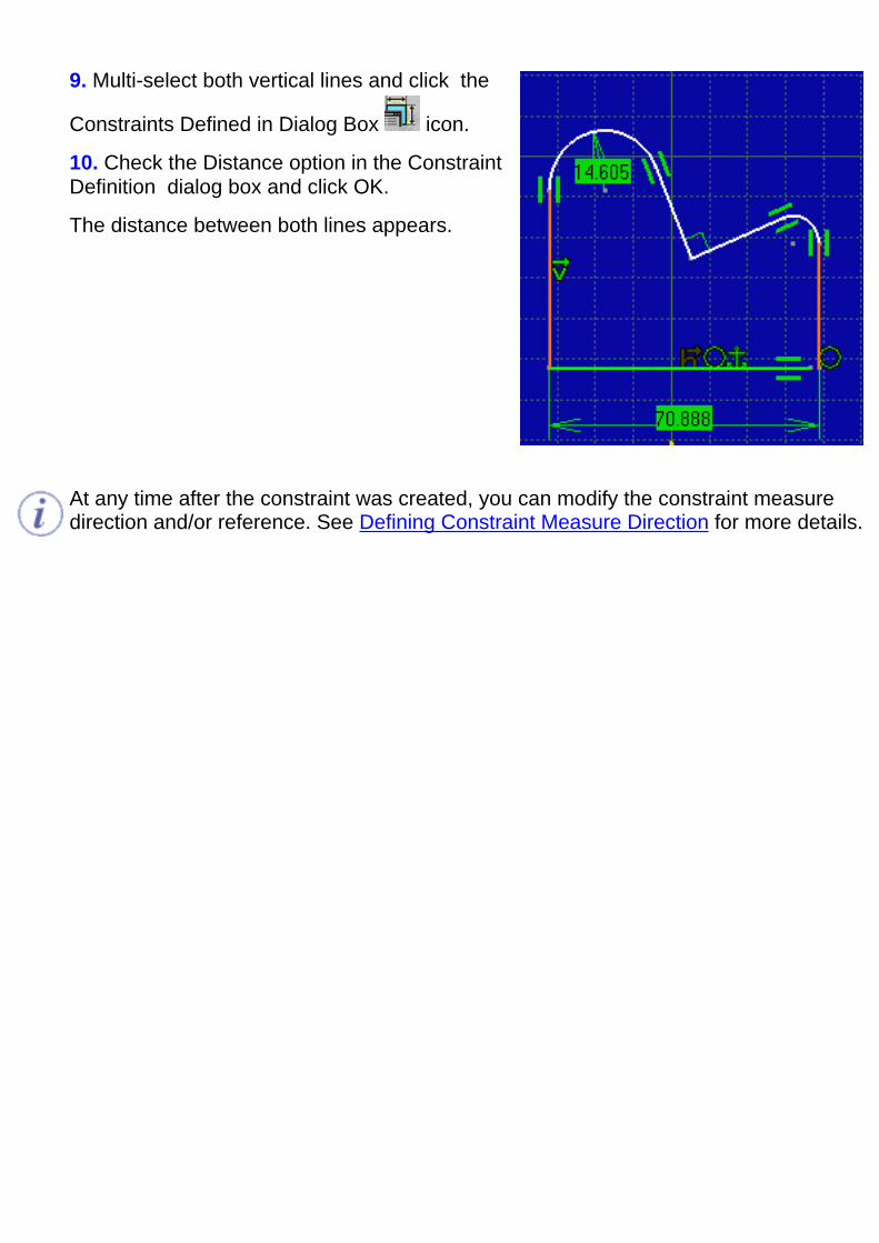
9. Multi-select both vertical lines and click the
Constraints Defined in Dialog Box icon.
10. Check the Distance option in the ConstraintDefinition dialog box and click OK.
The distance between both lines appears.
At any time after the constraint was created, you can modify the constraint measuredirection and/or reference. See Defining Constraint Measure Direction for more details.

Modifying Constraints On/BetweenElements
This task shows you how to edit geometrical constraints defined in the Sketcher or inthe 3D area.Open the Constraint_Definition.CATPart document and double-click Sketch1 in thespecification tree.
1. Select the right vertical line and click the
Constraint command from theConstraint toolbar.The Constraint Definition dialog box appears.
2. Check Length and Verticality.
3. Click OK to apply the modification.
The line is vertical.

4. Select the left vertical line and click the Constraint command .
The Constraint Definition dialog box appears, indicating that a verticality constraint isalready defined for the line.
5. Uncheck Verticality to remove the verticality constraint.
6. Click OK to apply the modification.
The symbol for verticality is removed.The profile now looks like this:
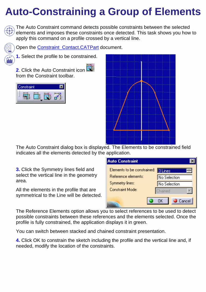
Auto-Constraining a Group of ElementsThe Auto Constraint command detects possible constraints between the selectedelements and imposes these constraints once detected. This task shows you how toapply this command on a profile crossed by a vertical line.
Open the Constraint_Contact.CATPart document.
1. Select the profile to be constrained.
2. Click the Auto Constraint icon from the Constraint toolbar.
The Auto Constraint dialog box is displayed. The Elements to be constrained fieldindicates all the elements detected by the application.
3. Click the Symmetry lines field andselect the vertical line in the geometryarea.
All the elements in the profile that aresymmetrical to the Line will be detected.
The Reference Elements option allows you to select references to be used to detectpossible constraints between these references and the elements selected. Once theprofile is fully constrained, the application displays it in green.
You can switch between stacked and chained constraint presentation.
4. Click OK to constrain the sketch including the profile and the vertical line and, ifneeded, modify the location of the constraints.

The constraints created are:Angle (111.918 and 137.023)Radius (10.721)Length (53.35)HorizontalityTangencyConcentricitySymmetry
The sketch is not displayed in greenbecause it is not constrained in relationto external elements (edges, planes andso on).
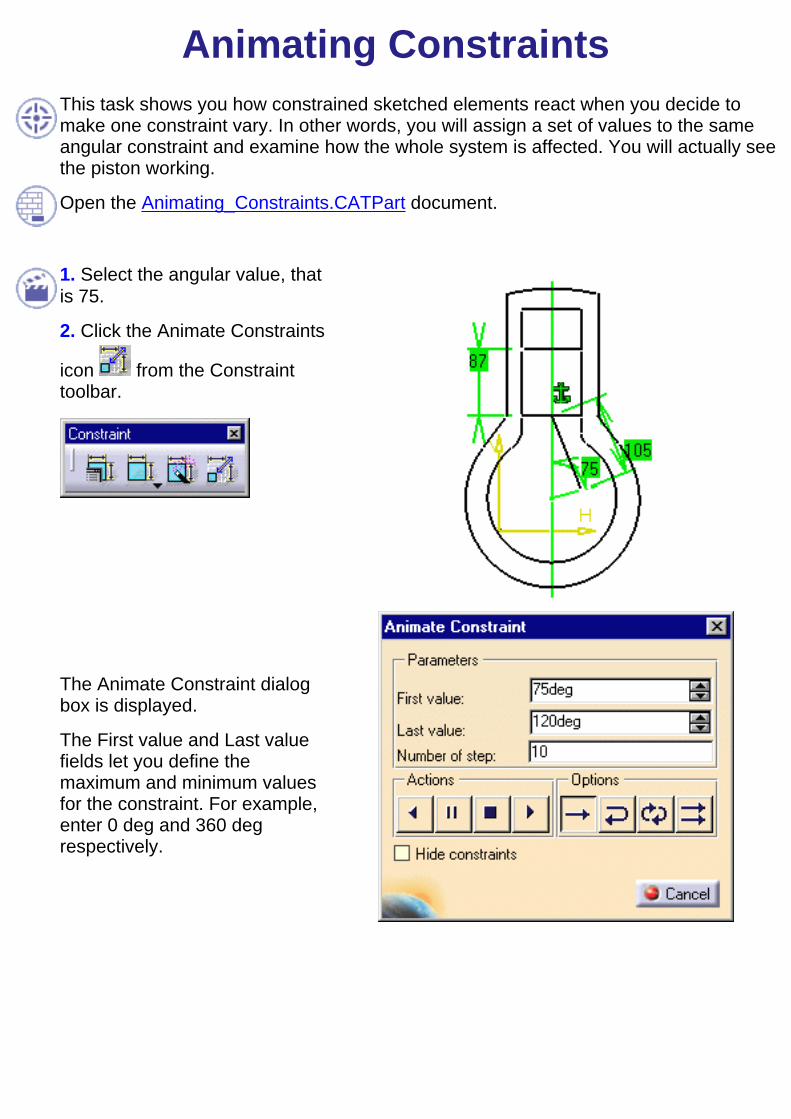
Animating ConstraintsThis task shows you how constrained sketched elements react when you decide tomake one constraint vary. In other words, you will assign a set of values to the sameangular constraint and examine how the whole system is affected. You will actually seethe piston working.
Open the Animating_Constraints.CATPart document.
1. Select the angular value, thatis 75.
2. Click the Animate Constraints
icon from the Constrainttoolbar.
The Animate Constraint dialogbox is displayed.
The First value and Last valuefields let you define themaximum and minimum valuesfor the constraint. For example,enter 0 deg and 360 degrespectively.

The Number of step field defines the number of values you wish to assign to theconstraint between the first and last values.
3. Enter 15 as Number of step value.
4. Click the Run animation button to see how the sketch is affected by thedifferent values assigned to the constraint. The edited sketch displays step by step.
The constrained value is set to115 degrees. The line and therectangle have been moved.
The constrained value is set to 246 degrees. Thecommand induces a clockwise rotation while movingthe rectangle up and down.
6. Check the Hide constraintsbox for hiding constraints. Thiscan be useful when there are alot of elements in the sketch.

7. Uncheck the Hide constraintsoption to display the constraintsagain. Once the maximum valueis reached, that is 360 degrees,the sketch looks like this:
Now, let's have a closer look at the dialog box.
ACTIONS:
run back: shows the different constraint values starting from the last value.In our scenario, we saw a counterclockwise rotation.
pause: stops the animation on the current value
stops: stops the animation and assigns the first value to the constraint
run: starts the command using the option defined (see below)
OPTIONS:
one shot: shows the animation only once
reverse: shows the animation from the first to the last value, then from thelast to the first value
loop: shows the animation from the first to the last value, then from the lastto the first and so on
repeat: repeats the animation many times from the beginning to the end

Workbench DescriptionThis section contains the description of the workbench icons and menus. Many of these commandsare discussed in greater details in other parts of the guide.
Sketcher Menu BarSketcher Toolbar

Sketcher ToolbarsThe table below lists the information you will find in this section:
ToolsSketcher
ConstraintsProfiles
Operations

Sketcher Toolbar
See Starting a Sketch See creating a Pad from "PartDesign" user's guide
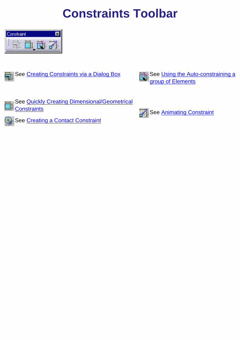
Constraints Toolbar
See Creating Constraints via a Dialog Box See Using the Auto-constraining agroup of Elements
See Quickly Creating Dimensional/GeometricalConstraints See Animating ConstraintSee Creating a Contact Constraint

Profiles Toolbar
See Profiles See Parabola
See Rectangles See Hyperbola
See Conic
See Oriented Rectangles See Basic Arcs
See Parallelograms See Arc Arcs Three Point
See Oblong Profiles See Arcs Three Point via Limits
See Oblong Arcs See Splines
See Keyhole See Connecting Elements
See Hexagons
See Lines See Bi-Tangent Line
See Infinite Line See Bisecting Line
See Axes
See Basic Circles See Points
See Three Point Circles See Points Using Coordinates
See Circles Using Coordinates See Equidistant Points
See Tri-Tangent Circle See Intersection
See Ellipses See Projection Point
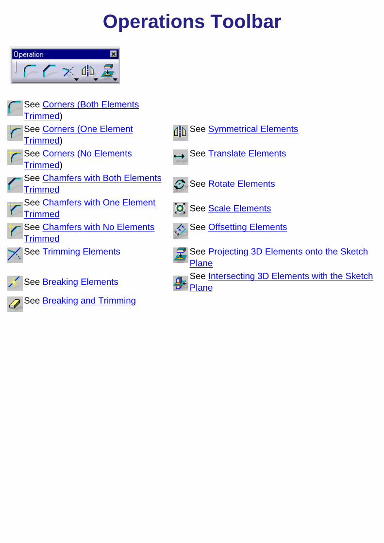
Operations Toolbar
See Corners (Both ElementsTrimmed)See Corners (One ElementTrimmed)
See Symmetrical Elements
See Corners (No ElementsTrimmed)
See Translate Elements
See Chamfers with Both ElementsTrimmed See Rotate Elements
See Chamfers with One ElementTrimmed See Scale Elements
See Chamfers with No ElementsTrimmed
See Offsetting Elements
See Trimming Elements See Projecting 3D Elements onto the SketchPlane
See Breaking Elements See Intersecting 3D Elements with the SketchPlane
See Breaking and Trimming
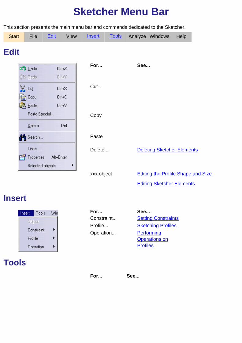
Sketcher Menu BarThis section presents the main menu bar and commands dedicated to the Sketcher.
Start File Edit View Insert Tools Analyze Windows Help
EditFor... See...
Cut...
Copy
Paste
Delete... Deleting Sketcher Elements
xxx.object Editing the Profile Shape and Size
Editing Sketcher Elements
InsertFor... See...Constraint... Setting ConstraintsProfile... Sketching ProfilesOperation... Performing
Operations onProfiles
ToolsFor... See...

Options... Customizing

CustomizingThe different types of setting customization you can perform are:
Sketcher:
Customize given options when creating Sketcher geometrical elements.

GlossaryA
autoconstraint A constraint applied to an iso-element (a group of elements).autodetection An assistant for visualizing and, if needed, creating constraints
between elements using the Sketcher.
Ccartesian coordinate The coordinates of an element defined according to the horizontal
and vertical position of this element. consecutive element An element that does not intersect with another element.constraint A geometric or dimension relation either on one element or between
two or three elements.
construction elementA construction element is an element that is internal to, and onlyvisualized by, the sketch. This element is used as positioningreference. It is not used for creating solid primitives.
control point A control point is a point which a spline (tangent) passes through.chamfer A cut through the thickness of the feature of an angle.
Ddriving constraint A constraint that drives the behaviour of the corresponding geometry.
Eexternal constraints Constraints between a selected element and other elements in the
sketch.
Iinternal constraints Constraints on a selected element or between a group of selected
elements.isobarycenter A center of gravity created between previously selected elements.
Ooffset A distance at which a duplicated line type element or curve type
element can be positioned.
Ppolar coordinate The coordinates of an element defined according to the radius and
the angle of this element.
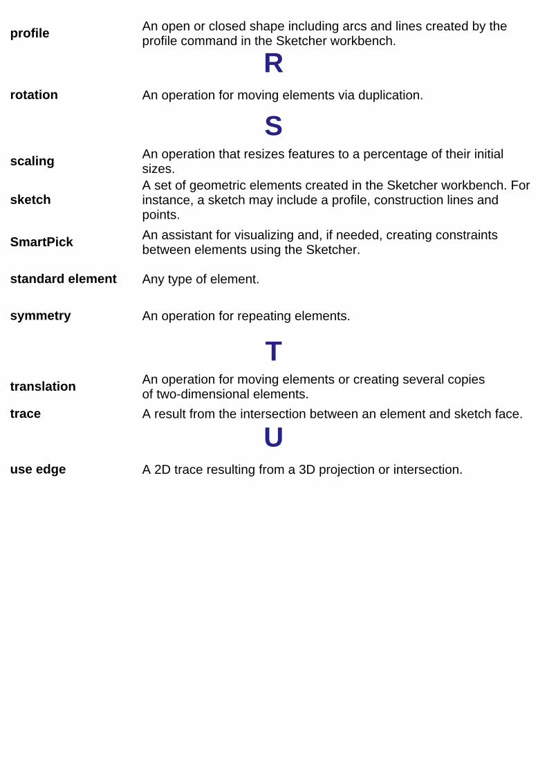
profile An open or closed shape including arcs and lines created by theprofile command in the Sketcher workbench.
Rrotation An operation for moving elements via duplication.
Sscaling An operation that resizes features to a percentage of their initial
sizes.
sketchA set of geometric elements created in the Sketcher workbench. Forinstance, a sketch may include a profile, construction lines andpoints.
SmartPick An assistant for visualizing and, if needed, creating constraintsbetween elements using the Sketcher.
standard element Any type of element.
symmetry An operation for repeating elements.
Ttranslation An operation for moving elements or creating several copies
of two-dimensional elements.trace A result from the intersection between an element and sketch face.
Uuse edge A 2D trace resulting from a 3D projection or intersection.

Index
A
analyzing animate constraint
commands
arc arc
commands
tangent
three points
three points using limits arc (three points using limits)
commands arc (three points)
commands arc(tangent)
commands autoconstraint
commands
autoconstraint
autosearch
axis axis
commands

B
bisecting line bisecting line
commands bi-tangent line
commands
creating
bi-tangent line
brackets
break break
commands
Ccenter point coordinates
circle chamfer
creating
chamfer with both elements trimmed chamfer with both elements trimmed
commands
chamfer with no element trimmed chamfer with no element trimmed
commands
chamfer with one element trimmed chamfer with one element trimmed
commands circle
center point coordinates
commands
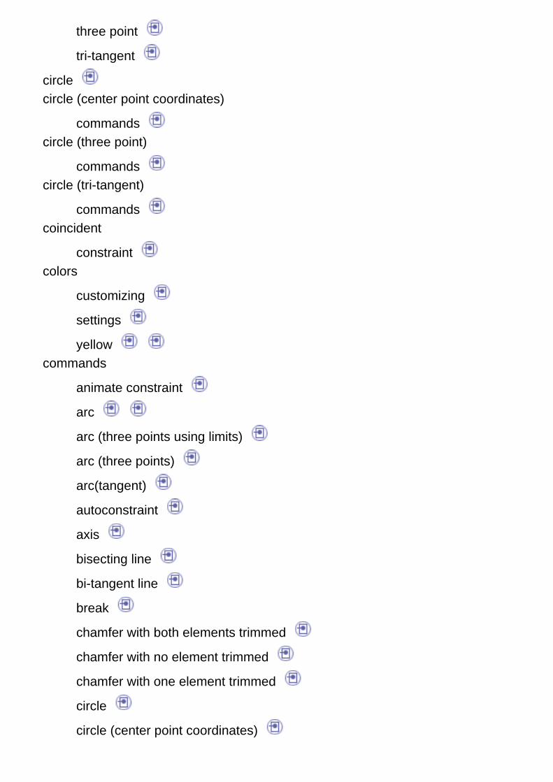
three point
tri-tangent
circle circle (center point coordinates)
commands circle (three point)
commands circle (tri-tangent)
commands coincident
constraint colors
customizing
settings
yellow commands
animate constraint
arc
arc (three points using limits)
arc (three points)
arc(tangent)
autoconstraint
axis
bisecting line
bi-tangent line
break
chamfer with both elements trimmed
chamfer with no element trimmed
chamfer with one element trimmed
circle
circle (center point coordinates)

circle (three point)
circle (tri-tangent)
concentricity
conic
connect
constraints
constraints via a dialog box
corner with no trimmed element
corner with only one line trimmed
curved oblong profile
cut part by sketch plane
ellipse
equidistant points
fix
geometrical constraints
hexagon
hyperbola by focus
infinite line
intersect 3D elements
isolate
keyhole
line
oblong arc
oblong profile
oriented rectangle
parabola by focus
parallelogram
point
point (equidistant)
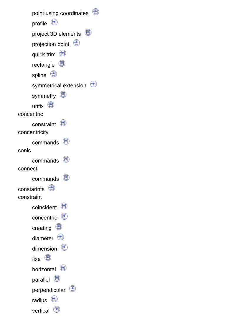
point using coordinates
profile
project 3D elements
projection point
quick trim
rectangle
spline
symmetrical extension
symmetry
unfix concentric
constraint concentricity
commands conic
commands connect
commands
constarints constraint
coincident
concentric
creating
diameter
dimension
fixe
horizontal
parallel
perpendicular
radius
vertical

constraints
commands constraints via a dialog box
commands construction element
creating
coordinates corner with no trimmed element
commands corner with only one line trimmed
commands corners
creating creating
bi-tangent line
chamfer
constraint
construction element
corners
elongated hole
hexagon
hyperbola by focus
infinite line
keyhole
line
oblong profile
oriented rectangle
parabola by focus
parallelogram
point
point using coordinates
profile
projection point
rectangle
settings
sketch plane
spline
symmetrical element
symmetrical extension curved oblong profile
commands customizing
colors cut part by sketch plane
commands
Ddeleting
profile diameter
constraint dimension
constraint
Eedit
spline
edit
edite editing
profile ellipse
commands elongated hole
creating equidistant points
commands
Ffix
commands fixe
constraint
Ggeometrical constraints
commands
geometry
grid
Hhexagon
commands
creating horizontal
constraint hyperbola by focus
commands

creating
Iinfinite line
commands
creating intersect 3D elements
commands
intersection marks isolate
commands
Kkeyhole
commands
creating
Lline
commands
creating
M
menubar
modify

Ooblong arc
commands oblong profile
commands
creating
offsetting oriented rectangle
commands
creating
Pparabola by focus
commands
creating parallel
constraint parallelogram
commands
creating
parents/children perpendicular
constraint point
commands
creating point (equidistant)
commands point using coordinates
commands

creating
profile profile
commands
creating
deleting
editing project 3D elements
commands
projection marks projection point
commands
creating
Qquick trim
commands
Rradius
constraint rectangle
commands
creating
replace
Ssettings
colors
creating sketch plane
creating
sketch plane
smartpick
snap to point spline
commands
creating
edit
starting a sketch symmetrical element
creating symmetrical extension
commands
creating symmetry
commands
Ttangent
arc three point
circle three points
arc three points using limits
arc
toolbar tri-tangent
circle
Uunfix
commands
Vvertical
constraint
W
workbench
Yyellow
colors