cb battery chargers - single phase · cb battery chargers - single phase with the cb battery...
TRANSCRIPT

CB Battery Chargers - Single Phase
With the CB Battery Charger Line, Altech offers a highly reliable battery managementsolution. Operating at single phase Input Voltages of 115-230-277 VAC, the devicessupply an Output of 12VDC and up to 35A or 24VDC and up to 20A.
Equipped with microcontrollers, the CB line offers fully automated multi-stage chargingthat will expand the batterie's life significantly. Several diagnostic and monitoringfeatures ensure easy handling and a high amount of transparency during daily operation.
Altech's CB line battery chargers are based on the switching technology which allowsmuch higher efficiency as well as smaller and lighter devices. Aditionally, severalstandard safety and protection features ensure safe installation and operation.
• Nominal Input Voltage 115-230-277VAC• Output Voltage 12VDC• Output Current 3, 6, 10, 35A• Adjustable Charging Current 20%-100% of Output Current• Working temperature: -25°C to 70°C• EMC standards: IEC/EN 60335-2-29,EN60950/UL1950,Electrical
safety,89/336/EEC,EMCDirective,2006/95/EC(Low Voltage),DIN41773(Charging cycle),Emission:IEC 61000-6-4,Immunity:IEC 61000-6-2.CE
• Nominal Input Voltage 115-230-277VAC• Output Voltage 24VDC• Output Current 3, 5, 10, 20A• Adjustable Charging Current 20%-100% of Output Current• Working temperature: -25°C to 70°C• EMC standards: IEC/EN 60335-2-29,EN60950/UL1950,Electrical
safety,89/336/EEC,EMCDirective,2006/95/EC(Low Voltage),DIN41773(Charging cycle),Emission:IEC 61000-6-4,Immunity: IEC 61000-6-2.CE

Via Luigi Barchi 9/B – Reggio Emilia 42124 – Italy Tel. +39 0522 345518 – Fax +39 0522 345551 – [email protected] www.adelsystem.com Instruction Manual CB120W CB240W CB489W_r0.doc
Pa
ge 1
- C
hapt
er: C
B120
W C
B240
W C
B480
W: S
mar
t Bat
tery
Cha
rger
s
CB120W CB240W CB480W: Smart Battery Chargers Thank you for having chosen one of our products for your work. We are certain that it will give the utmost satisfaction and be a notable help on the job.
General Description The CB series is a “Switching technology” and “Battery Care philosophy” since many years parts of the know-how ADEL system, led to the development of this advanced multi-stage battery charging , completely automatic and suited to meet the most advanced requirements of battery manufacturers. The Battery Care concept is base on algorithms that implement rapid and automatic cycle of battery charging, battery charge optimization during time, flat batteries recovery and real time diagnostic during installation and operation. The Real Time Auto-diagnostic system, monitoring battery faults such as, elements in short circuit, accidental reverse polarity connection, disconnection of the battery, they can easily be detected and removed by help of Blink Code of Diagnosis Led; during the installation
and after sell. Each device is suited for all battery types, jumper selection sets a predefined curves for: Open Lead Acid, Sealed Lead Acid, Gel, Ni-Cd and Ni-Mh. A rugged casing with bracket for DIN rail mounting provide IP20 protection degree.
Main Characteristics • Input: Single-phase 115 – 230 Vac • Output Battery: charging: 24 Vdc 5A – 10A – 20 A
12 Vdc 10 – 35 A; • Suited for the following battery types: Open Lead Acid,
Sealed Lead Acid, Lead Gel, Ni-Cd and Ni-Mh • Automatic diagnostic of battery status. Charging curve
IUoUO, constant voltage and constant current Battery Life Test function (Battery Care)
• Switching technology- • Three charging levels: Boost, Trickle and Recovery • Protected against short circuit, Over Load and inverted
polarity • Signal output (contact free) for discharged or damaged
battery • Signal output (contact free) for Mains or Back-Up • Protection degree IP20 - DIN rail; Space saving
Safety and warning notes WARNING – Explosion Hazard Do not disconnect Equipment unless power has been switched off or the area is
known to be non-hazardous. WARNING – Explosion Hazard. Substitution of components may impair suitability for class I, Division 2. WARNING – Switch off the system before connecting the module. Never work on the machine when it is live. The device must be installed in according with UL508. The device must have a suitable isolating facility outside the power supply unit, via which can be switched to idle. Danger of fatal Injury!
Connection (terminal and wiring): Cable Connection: The following cable cross-sections may be used:
Solid (mm2)
Stranded (mm2) AWG Torque (Nm) Stripping
Length All In One
(Size) 1 Phase L N PE
Input AC 1 Phase L N PE
Input AC 0.2 – 2.5 0.2 – 2.5 24 – 14 0.5 – 0.6 Nm 7 mm Size 1 and 2In: 4.0 6.0 30 – 10 0.8 – 1.0 Nm 7 mm Size 3 0.2 – 2.5 0.2 – 2.5 24 – 14 0.5 – 0.6 Nm 7 mm Size 1 and 2Out: 4.0 6.0 30 – 10 0.8 – 1.0 Nm 7 mm Size 3
Signal: 0.2 – 2.5 0.2 – 2.5 24 – 14 0.5 – 0.6 Nm 7 mm All types
The connection is made by the screw type 2.5 mm2 or 4.0 mm2 (CB2420A – CB1235A) terminal blocks. Use only copper cables that are designed for operating temperatures of > 75 °C. Wiring terminal shall be marked to indicate the proper connection for the power supply.
Pa
ge 3
- C
hapt
er: O
pera
ting
and
Dis
play
Ele
men
t:
(1) For better efficiency of the system, filter relay Mains/Back up with a delay of at least 5 seconds before give alarm Main Lost, example: connection to PLC. (2) See Diagnosis Led
No. 6, 7 and 8 Display Signals No.6: Led Mains/Back Up: Input Mains On/Off No.7: Led Low Battery(capacity less than 30%), Fault connections systems, Battery replacement. No.8: Led Battery charge mode, Led Diagnosis. Diagnosis of the system through “blinking code” signal
Monitoring Control
Chart: State LED Diagnosis
(No.8) LED Battery Fault (No.7)
Trickle 1 Blink/sec OFF Boost 2 Blink/sec OFF
Charging Type
Recovery 5 Blink/sec OFF Reverse polarity or high battery Voltage (over 32.5Vdc for CB24xx) 1 Blink/pause ON
Battery No connected 2 Blink/pause ON Element in Short Circuit 3 Blink/pause ON Bad battery; Internal impedance Bad or Bad battery wire connection. 5 Blink/pause ON
Life test not possible 6 Blink/pause ON Bad thermal sensor 7 Blink/pause ON Internal fault 9 Blink/pause ON CAN bus error 11 Blink/pause Life test not possible; Parallel mode on Slave Device 12 Blink/pause Bad battery wire connection; Parallel mode on Slave Device 13 Blink/pause
Auto diagnosis of the system
No. 12: Battery Management Configurations Preliminary Operations: One device for all battery types. Completely automatic, all devices are suitable to charge most batteries types thank to User Selectable charging curves. They can charge open lead acid, sealed lead acid, Gel and Ni-Cd, Ni-MH batteries. It is possible to change or add other charging curves connecting the device to a portable PC. Caution: Switch off the system before Setting the jumper.
Battery Type Selection
Jumper Position (Size 1 and Size 3)
Jumper Position (Size 2)
Trickle/Float charge (Volt/Cell)
Fast/Bulk charge (Volt/Cell)
Open Lead 2.23 2.40
Sealed Lead Low 2.25 2.40
Sealed Lead High 2.27 2.40
Gel Battery 2.30 2.40
Gel Battery (1) 2.30 2.40
NiCd – NiMh (1) 10% Imax Trimmer 1.70–(12V);1.5–(24V)
Functional Setting Function
Battery Life test ON Jumper present: Life test enabled.
Fast Charge Enable Jumper present: fast charge enabled.
Fast Recovery Charge (2) Not available
Jumper present: Fast Recovery Charge, enabled only for Size 3. Possibility to recharge the battery also when the voltage is close to Zero with the maximum power of the device.
Notice: 1 Be care full, in NiCd-NiMh Option, the Sealed Lead High charging curve is deleted.
NiCd-NiMh (Options to be defined by Order). End-of-charge determined by negative ∆V detection of battery voltage (-5mV/cell). If no negative ∆V but only a “flat” profile is detected fast charge is terminated after 10 min.
Pa
ge 5
- C
hapt
er: P
rote
ctio
n Fe
atur
es
Charging Curve Automatic multi-stage operation and real time diagnostic allows fast recharge and recovery of deep discharged batteries, adding value and reliability to the system hosting the CBxxyy device. The type of charging is Voltages stabilized and Current stabilized IUoUo. Three charging modes are identified by a flashing code on a Diagnosis LED.
State Diagnosis LED Battery Fault LED Trickle 1 Blink/sec OFF Boost 2 Blink/sec OFF Charging Type Recovery 5 Blink/sec OFF
Compensation Recharges in temperature (For SIZE 2: CB2410 require /ARJ code)
Connecting to RJ45 Auxiliary Output the cable RJTEMP (supplied separately), the CB will vary the voltage of battery charging in depending of the temperature:
CBI Model Fast Charge Trickle charge CBI12xx (12Vdc) -2.5mV/°C -1.5mV/°C CBI24xx (24Vdc) -5mV/°C -3mV/°C CBI48xx (48Vdc) -10mV/°C -6mV/°C
The sensor place on cable RJTEMP must be applied on the battery. If the sensor is not connected or if the sensor is defective, the led Low Batt is on and the led Diagnosis continues to show the status of the battery: trickle charge, fast charge or recovery charge.
Protection Features On the primary side: the device is equipped whit an internal fuse. If the internal fuse is activated, it is most probable that there is a fault in the device. If happen, the device must be checked in the factory. On the secondary side Battery: The device is electrically protected against short circuits and overload. Inversion polarity: the module it is automatically protected against inversion of battery polarity. Deep discharge : not possible. The unit disconnects the battery when a minimum voltage level is reached.
Pa
ge 2
- C
hapt
er: O
utpu
t Pow
er c
onne
ctio
ns:
Size 1 Size 2 Size 3
Output Power connections:
Normal connection
Typical application for CBxxyy device: N°1 battery (12 Vdc) for CB12yy; N°2 battery (12 Vdc) connected in Series for CB24yy;
Operating and Display Element:
No. 10: Input AC Port pin. L – N: 1 Phase Switching Power Supplies L, N, PE . Size 2 and Size 3 BRIDGE ONLY for input 115 Vac, and connect L, N, PE .
No. 3: Battery Connection Port: Connect the battery between pin. 3 (–) and 4 (+) One battery (12 Vdc) for CB12yy; Two battery (12 Vdc) connected in Series for CB24yy;
No. 1, 2 Signal Ports (output Isolated): Connections for, No. 2: Mains/Back Up: Input Mains On/Off. Contact: 5,6,7 No. 1: Low Battery, Fault connections systems, Battery replacement. Contact: 8,9,10 Relay Contact Rating: Max.DC1: 30 Vdc 1 A; AC1: 60 Vac 1A : Resistive load (EN 60947-4-1)
Min.1mA at 5 Vdc: Min. permissive load Signal Output port true table:
Port N°2 - Led N°6 Mains/Back-Up Port N°1 - Led N°7 Fault Battery
5-6 Closed 5-7 Closed 8-9 Closed (OK)
8-10 Closed
ON ■ - led off ■ - led off Mains Input Vac OFF ■ - led On (1) ■ - led off YES ■ - led On ■ - led On The battery in
BackUP it is less than 30% cap?
NO ■ - led On ■ - led off
YES ■ - led off ■ - led On (2) Battery or system Fault? NO ■ - led off ■ - led off
Note:
3
5
6
7
8
10
11
2 1 11
12 10 10 3
3
11
1 2 2 1
6 7 8 6 7 8 12
12
14
Pa
ge 4
- C
hapt
er: B
atte
ry C
are
General end-of-charge timeout set to 16 hours. Trickle charge current is regulated at 10% of max current corresponding to trimmer position. In order to detect end-of-charge negative ∆V, charging current must be set at least at 30% of nominal battery capacity (0,3 C); with lower values of charging current negative ∆V detection is not guaranteed.
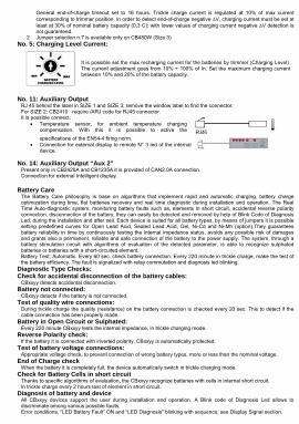
2 Jumper selection n.7 is available only on CB480W (Size 3) No. 5: Charging Level Current:
It is possible set the max recharging current for the batteries by trimmer (Charging Level). The current adjustment goes from 10% ÷ 100% of In. Set the maximum charging current between 10% and 20% of the battery capacity.
No. 11: Auxiliary Output
RJ 45 behind the label in SIZE 1 and SIZE 3; remove the window label to find the connector, For SIZE 2: CB2410 require /ARJ code for RJ45 connector. It is possible connect:
• Temperature sensor, for ambient temperature charging compensation. With this it is possible to active the specifications of the EN54-4 firing norm.
• Connection for external display to remote N° 3 led of the internal device.
No. 14: Auxiliary Output “Aux 2”
Present only in CB2420A and CB1235A it is provided of CAN2.0A connection. Connection for external Intelligent display.
Battery Care The Battery Care philosophy is base on algorithms that implement rapid and automatic charging, battery charge optimization during time, flat batteries recovery and real time diagnostic during installation and operation. The Real Time Auto-diagnostic system, monitoring battery faults such as, elements in short circuit, accidental reverse polarity connection, disconnection of the battery, they can easily be detected and removed by help of Blink Code of Diagnosis Led; during the installation and after sell. Each device is suited for all battery types, by means of jumpers it is possible setting predefined curves for Open Lead Acid, Sealed Lead Acid, Gel, Ni-Cd and Ni-Mh (option).They guarantees battery reliability in time by continuously testing the internal impedance status, avoids any possible risk of damages and grants also a permanent, reliable and safe connection of the battery to the power supply. The system, through a battery stimulation circuit with algorithms of evaluation of the detected parameter, is able to recognize sulphated batteries or batteries with a short-circuited element. Battery Test: Automatic. Every 60 sec. check battery connection. Every 220 minute in trickle charge, make the test of the battery efficiency. The fault is signalized with relay commutation and diagnosis led blinking.
Diagnostic Type Checks: Check for accidental disconnection of the battery cables:
CBxxyy detects accidental disconnection. Battery not connected:
CBxxyy detects if the battery is not connected. Test of quality wire connections:
During trickle charge the quality (resistance) on the battery connection is checked every 20 sec. This to detect if the cable connection has been properly made.
Battery in Open Circuit or Sulphated: Every 220 minute CBxxyy tests the internal impedance, in trickle charging mode.
Reverse Polarity check: If the battery it is connected with inverted polarity, CBxxyy is automatically protected.
Test of battery voltage connections: Appropriate voltage check, to prevent connection of wrong battery types, more or less than the nominal voltage.
End of Charge check
When the battery it is completely full, the device automatically switch in trickle charging mode. Check for Battery Cells in short circuit
Thanks to specific algorithms of evaluation, the CBxxyy recognize batteries with cells in internal short circuit. In trickle charge every 2 hours test of element in short circuit.
Diagnosis of battery and device All CBxxyy devices support the user during installation and operation. A Blink code of Diagnosis Led allows to discriminate among various possible faults. Error conditions, “LED Battery Fault” ON and “LED Diagnosis” blinking with sequence; see Display Signal section.
Pa
ge 6
- C
hapt
er: T
herm
al b
ehav
iour
Thermal behaviour
Surrounding air temperature 50°C. For ambient temperature of over 50°C, the output current must be reduced by 2.5% per °C. Max 70°C At the temperature of 70°C the output current will be 50% of In. The equipment does not switch off in case of ambient temperature above 70°C or thermal overload. The devices are protected for Over temperature conditions “worst case”; in this situations the device Shut-down the output and automatic restart when temperature inside fall.
Standards and Certification Electrical Safety: Assembling device: UL508, IEC/EN 60950 (VDE 0805) and EN 50178 (VDE 0160). Installation according: IEC/EN 60950. Input / Output separation: SELV EN 60950-1 and PELV EN 60204-1. Double or reinforced insulation. EMC Standards Immunity: EN 61000-4-2, EN 61000-4-3, EN 61000-4-4, EN 61000-4-5. EMC Standards Emission: EN 61000-6-4, EN 61000-6-3, EN 61000-3-2 (see data sheet for each device) Standards Conformity: Safety of Electrical Equipment Machines: EN 60204-1.
The CE mark in According to EMC 2004/108/EC and Low voltage directive 2006/95/EEC
Norms and Certifications In Conformity to: IEC/EN 60335-2-29 Battery chargers; EN60950 / UL1950; Electrical safety EN54-4 Fire Detection and fire alarm systems; 89/336/EEC EMC Directive; 2006/95/EC (Low Voltage); DIN41773 (Charging cycle); Emission: IEC 61000-6-4; Immunity: IEC 61000-6-2. CE.
Rail Mounting:
All modules must have a minimum vertical and horizontal distance of 10 cm to this power supply in order to guarantee sufficient auto convection. Depending on the ambient temperature and load of the device, the temperature of the housing can become very high!

Via Luigi Barchi 9/B – Reggio Emilia 42124 – Italy Tel. +39 0522 345518 – Fax +39 0522 345551 – [email protected] www.adelsystem.com Instruction Manual CB120W CB240W CB489W_r0.doc
Pa
ge 1
- C
hapt
er: C
B120
W C
B240
W C
B480
W: S
mar
t Bat
tery
Cha
rger
s
CB120W CB240W CB480W: Smart Battery Chargers Thank you for having chosen one of our products for your work. We are certain that it will give the utmost satisfaction and be a notable help on the job.
General Description The CB series is a “Switching technology” and “Battery Care philosophy” since many years parts of the know-how ADEL system, led to the development of this advanced multi-stage battery charging , completely automatic and suited to meet the most advanced requirements of battery manufacturers. The Battery Care concept is base on algorithms that implement rapid and automatic cycle of battery charging, battery charge optimization during time, flat batteries recovery and real time diagnostic during installation and operation. The Real Time Auto-diagnostic system, monitoring battery faults such as, elements in short circuit, accidental reverse polarity connection, disconnection of the battery, they can easily be detected and removed by help of Blink Code of Diagnosis Led; during the installation
and after sell. Each device is suited for all battery types, jumper selection sets a predefined curves for: Open Lead Acid, Sealed Lead Acid, Gel, Ni-Cd and Ni-Mh. A rugged casing with bracket for DIN rail mounting provide IP20 protection degree.
Main Characteristics • Input: Single-phase 115 – 230 Vac • Output Battery: charging: 24 Vdc 5A – 10A – 20 A
12 Vdc 10 – 35 A; • Suited for the following battery types: Open Lead Acid,
Sealed Lead Acid, Lead Gel, Ni-Cd and Ni-Mh • Automatic diagnostic of battery status. Charging curve
IUoUO, constant voltage and constant current Battery Life Test function (Battery Care)
• Switching technology- • Three charging levels: Boost, Trickle and Recovery • Protected against short circuit, Over Load and inverted
polarity • Signal output (contact free) for discharged or damaged
battery • Signal output (contact free) for Mains or Back-Up • Protection degree IP20 - DIN rail; Space saving
Safety and warning notes WARNING – Explosion Hazard Do not disconnect Equipment unless power has been switched off or the area is
known to be non-hazardous. WARNING – Explosion Hazard. Substitution of components may impair suitability for class I, Division 2. WARNING – Switch off the system before connecting the module. Never work on the machine when it is live. The device must be installed in according with UL508. The device must have a suitable isolating facility outside the power supply unit, via which can be switched to idle. Danger of fatal Injury!
Connection (terminal and wiring): Cable Connection: The following cable cross-sections may be used:
Solid (mm2)
Stranded (mm2) AWG Torque (Nm) Stripping
Length All In One
(Size) 1 Phase L N PE
Input AC 1 Phase L N PE
Input AC 0.2 – 2.5 0.2 – 2.5 24 – 14 0.5 – 0.6 Nm 7 mm Size 1 and 2In: 4.0 6.0 30 – 10 0.8 – 1.0 Nm 7 mm Size 3 0.2 – 2.5 0.2 – 2.5 24 – 14 0.5 – 0.6 Nm 7 mm Size 1 and 2Out: 4.0 6.0 30 – 10 0.8 – 1.0 Nm 7 mm Size 3
Signal: 0.2 – 2.5 0.2 – 2.5 24 – 14 0.5 – 0.6 Nm 7 mm All types
The connection is made by the screw type 2.5 mm2 or 4.0 mm2 (CB2420A – CB1235A) terminal blocks. Use only copper cables that are designed for operating temperatures of > 75 °C. Wiring terminal shall be marked to indicate the proper connection for the power supply.
Pa
ge 3
- C
hapt
er: O
pera
ting
and
Dis
play
Ele
men
t:
(1) For better efficiency of the system, filter relay Mains/Back up with a delay of at least 5 seconds before give alarm Main Lost, example: connection to PLC. (2) See Diagnosis Led
No. 6, 7 and 8 Display Signals No.6: Led Mains/Back Up: Input Mains On/Off No.7: Led Low Battery(capacity less than 30%), Fault connections systems, Battery replacement. No.8: Led Battery charge mode, Led Diagnosis. Diagnosis of the system through “blinking code” signal
Monitoring Control
Chart: State LED Diagnosis
(No.8) LED Battery Fault (No.7)
Trickle 1 Blink/sec OFF Boost 2 Blink/sec OFF
Charging Type
Recovery 5 Blink/sec OFF Reverse polarity or high battery Voltage (over 32.5Vdc for CB24xx) 1 Blink/pause ON
Battery No connected 2 Blink/pause ON Element in Short Circuit 3 Blink/pause ON Bad battery; Internal impedance Bad or Bad battery wire connection. 5 Blink/pause ON
Life test not possible 6 Blink/pause ON Bad thermal sensor 7 Blink/pause ON Internal fault 9 Blink/pause ON CAN bus error 11 Blink/pause Life test not possible; Parallel mode on Slave Device 12 Blink/pause Bad battery wire connection; Parallel mode on Slave Device 13 Blink/pause
Auto diagnosis of the system
No. 12: Battery Management Configurations Preliminary Operations: One device for all battery types. Completely automatic, all devices are suitable to charge most batteries types thank to User Selectable charging curves. They can charge open lead acid, sealed lead acid, Gel and Ni-Cd, Ni-MH batteries. It is possible to change or add other charging curves connecting the device to a portable PC. Caution: Switch off the system before Setting the jumper.
Battery Type Selection
Jumper Position (Size 1 and Size 3)
Jumper Position (Size 2)
Trickle/Float charge (Volt/Cell)
Fast/Bulk charge (Volt/Cell)
Open Lead 2.23 2.40
Sealed Lead Low 2.25 2.40
Sealed Lead High 2.27 2.40
Gel Battery 2.30 2.40
Gel Battery (1) 2.30 2.40
NiCd – NiMh (1) 10% Imax Trimmer 1.70–(12V);1.5–(24V)
Functional Setting Function
Battery Life test ON Jumper present: Life test enabled.
Fast Charge Enable Jumper present: fast charge enabled.
Fast Recovery Charge (2) Not available
Jumper present: Fast Recovery Charge, enabled only for Size 3. Possibility to recharge the battery also when the voltage is close to Zero with the maximum power of the device.
Notice: 1 Be care full, in NiCd-NiMh Option, the Sealed Lead High charging curve is deleted.
NiCd-NiMh (Options to be defined by Order). End-of-charge determined by negative ∆V detection of battery voltage (-5mV/cell). If no negative ∆V but only a “flat” profile is detected fast charge is terminated after 10 min.
Pa
ge 5
- C
hapt
er: P
rote
ctio
n Fe
atur
es
Charging Curve Automatic multi-stage operation and real time diagnostic allows fast recharge and recovery of deep discharged batteries, adding value and reliability to the system hosting the CBxxyy device. The type of charging is Voltages stabilized and Current stabilized IUoUo. Three charging modes are identified by a flashing code on a Diagnosis LED.
State Diagnosis LED Battery Fault LED Trickle 1 Blink/sec OFF Boost 2 Blink/sec OFF Charging Type Recovery 5 Blink/sec OFF
Compensation Recharges in temperature (For SIZE 2: CB2410 require /ARJ code)
Connecting to RJ45 Auxiliary Output the cable RJTEMP (supplied separately), the CB will vary the voltage of battery charging in depending of the temperature:
CBI Model Fast Charge Trickle charge CBI12xx (12Vdc) -2.5mV/°C -1.5mV/°C CBI24xx (24Vdc) -5mV/°C -3mV/°C CBI48xx (48Vdc) -10mV/°C -6mV/°C
The sensor place on cable RJTEMP must be applied on the battery. If the sensor is not connected or if the sensor is defective, the led Low Batt is on and the led Diagnosis continues to show the status of the battery: trickle charge, fast charge or recovery charge.
Protection Features On the primary side: the device is equipped whit an internal fuse. If the internal fuse is activated, it is most probable that there is a fault in the device. If happen, the device must be checked in the factory. On the secondary side Battery: The device is electrically protected against short circuits and overload. Inversion polarity: the module it is automatically protected against inversion of battery polarity. Deep discharge : not possible. The unit disconnects the battery when a minimum voltage level is reached.
Pa
ge 2
- C
hapt
er: O
utpu
t Pow
er c
onne
ctio
ns:
Size 1 Size 2 Size 3
Output Power connections:
Normal connection
Typical application for CBxxyy device: N°1 battery (12 Vdc) for CB12yy; N°2 battery (12 Vdc) connected in Series for CB24yy;
Operating and Display Element:
No. 10: Input AC Port pin. L – N: 1 Phase Switching Power Supplies L, N, PE . Size 2 and Size 3 BRIDGE ONLY for input 115 Vac, and connect L, N, PE .
No. 3: Battery Connection Port: Connect the battery between pin. 3 (–) and 4 (+) One battery (12 Vdc) for CB12yy; Two battery (12 Vdc) connected in Series for CB24yy;
No. 1, 2 Signal Ports (output Isolated): Connections for, No. 2: Mains/Back Up: Input Mains On/Off. Contact: 5,6,7 No. 1: Low Battery, Fault connections systems, Battery replacement. Contact: 8,9,10 Relay Contact Rating: Max.DC1: 30 Vdc 1 A; AC1: 60 Vac 1A : Resistive load (EN 60947-4-1)
Min.1mA at 5 Vdc: Min. permissive load Signal Output port true table:
Port N°2 - Led N°6 Mains/Back-Up Port N°1 - Led N°7 Fault Battery
5-6 Closed 5-7 Closed 8-9 Closed (OK)
8-10 Closed
ON ■ - led off ■ - led off Mains Input Vac OFF ■ - led On (1) ■ - led off YES ■ - led On ■ - led On The battery in
BackUP it is less than 30% cap?
NO ■ - led On ■ - led off
YES ■ - led off ■ - led On (2) Battery or system Fault? NO ■ - led off ■ - led off
Note:
3
5
6
7
8
10
11
2 1 11
12 10 10 3
3
11
1 2 2 1
6 7 8 6 7 8 12
12
14
Pa
ge 4
- C
hapt
er: B
atte
ry C
are
General end-of-charge timeout set to 16 hours. Trickle charge current is regulated at 10% of max current corresponding to trimmer position. In order to detect end-of-charge negative ∆V, charging current must be set at least at 30% of nominal battery capacity (0,3 C); with lower values of charging current negative ∆V detection is not guaranteed.
2 Jumper selection n.7 is available only on CB480W (Size 3) No. 5: Charging Level Current:
It is possible set the max recharging current for the batteries by trimmer (Charging Level). The current adjustment goes from 10% ÷ 100% of In. Set the maximum charging current between 10% and 20% of the battery capacity.
No. 11: Auxiliary Output
RJ 45 behind the label in SIZE 1 and SIZE 3; remove the window label to find the connector, For SIZE 2: CB2410 require /ARJ code for RJ45 connector. It is possible connect:
• Temperature sensor, for ambient temperature charging compensation. With this it is possible to active the specifications of the EN54-4 firing norm.
• Connection for external display to remote N° 3 led of the internal device.
No. 14: Auxiliary Output “Aux 2”
Present only in CB2420A and CB1235A it is provided of CAN2.0A connection. Connection for external Intelligent display.
Battery Care The Battery Care philosophy is base on algorithms that implement rapid and automatic charging, battery charge optimization during time, flat batteries recovery and real time diagnostic during installation and operation. The Real Time Auto-diagnostic system, monitoring battery faults such as, elements in short circuit, accidental reverse polarity connection, disconnection of the battery, they can easily be detected and removed by help of Blink Code of Diagnosis Led; during the installation and after sell. Each device is suited for all battery types, by means of jumpers it is possible setting predefined curves for Open Lead Acid, Sealed Lead Acid, Gel, Ni-Cd and Ni-Mh (option).They guarantees battery reliability in time by continuously testing the internal impedance status, avoids any possible risk of damages and grants also a permanent, reliable and safe connection of the battery to the power supply. The system, through a battery stimulation circuit with algorithms of evaluation of the detected parameter, is able to recognize sulphated batteries or batteries with a short-circuited element. Battery Test: Automatic. Every 60 sec. check battery connection. Every 220 minute in trickle charge, make the test of the battery efficiency. The fault is signalized with relay commutation and diagnosis led blinking.
Diagnostic Type Checks: Check for accidental disconnection of the battery cables:
CBxxyy detects accidental disconnection. Battery not connected:
CBxxyy detects if the battery is not connected. Test of quality wire connections:
During trickle charge the quality (resistance) on the battery connection is checked every 20 sec. This to detect if the cable connection has been properly made.
Battery in Open Circuit or Sulphated: Every 220 minute CBxxyy tests the internal impedance, in trickle charging mode.
Reverse Polarity check: If the battery it is connected with inverted polarity, CBxxyy is automatically protected.
Test of battery voltage connections: Appropriate voltage check, to prevent connection of wrong battery types, more or less than the nominal voltage.
End of Charge check
When the battery it is completely full, the device automatically switch in trickle charging mode. Check for Battery Cells in short circuit
Thanks to specific algorithms of evaluation, the CBxxyy recognize batteries with cells in internal short circuit. In trickle charge every 2 hours test of element in short circuit.
Diagnosis of battery and device All CBxxyy devices support the user during installation and operation. A Blink code of Diagnosis Led allows to discriminate among various possible faults. Error conditions, “LED Battery Fault” ON and “LED Diagnosis” blinking with sequence; see Display Signal section.
Pa
ge 6
- C
hapt
er: T
herm
al b
ehav
iour
Thermal behaviour
Surrounding air temperature 50°C. For ambient temperature of over 50°C, the output current must be reduced by 2.5% per °C. Max 70°C At the temperature of 70°C the output current will be 50% of In. The equipment does not switch off in case of ambient temperature above 70°C or thermal overload. The devices are protected for Over temperature conditions “worst case”; in this situations the device Shut-down the output and automatic restart when temperature inside fall.
Standards and Certification Electrical Safety: Assembling device: UL508, IEC/EN 60950 (VDE 0805) and EN 50178 (VDE 0160). Installation according: IEC/EN 60950. Input / Output separation: SELV EN 60950-1 and PELV EN 60204-1. Double or reinforced insulation. EMC Standards Immunity: EN 61000-4-2, EN 61000-4-3, EN 61000-4-4, EN 61000-4-5. EMC Standards Emission: EN 61000-6-4, EN 61000-6-3, EN 61000-3-2 (see data sheet for each device) Standards Conformity: Safety of Electrical Equipment Machines: EN 60204-1.
The CE mark in According to EMC 2004/108/EC and Low voltage directive 2006/95/EEC
Norms and Certifications In Conformity to: IEC/EN 60335-2-29 Battery chargers; EN60950 / UL1950; Electrical safety EN54-4 Fire Detection and fire alarm systems; 89/336/EEC EMC Directive; 2006/95/EC (Low Voltage); DIN41773 (Charging cycle); Emission: IEC 61000-6-4; Immunity: IEC 61000-6-2. CE.
Rail Mounting:
All modules must have a minimum vertical and horizontal distance of 10 cm to this power supply in order to guarantee sufficient auto convection. Depending on the ambient temperature and load of the device, the temperature of the housing can become very high!

www.adesystem.com
CB Battery Charger
Input (Volt) 115 – 230Vac 115 – 230Vac 115 – 230Vac 115 – 230Vac 115 – 230Vac
Output (Vdc – A – W) 12Vdc – 10A – 120W 12Vdc – 35A – 480W 24Vdc – 5A – 120W 24Vdc – 10A – 240W 24Vdc – 20A – 480W
Model CB1210A CB1235A CB245A CB2410AC CB2420A
INPUT DATANominal Input Voltage / Tensione d’ingresso nominale 115 – 230Vac 115 – 230Vac 115 – 230Vac 115 – 230Vac 115 – 230Vac
Input Voltage Range / Campo di funzionamento 90 – 264Vac 90 – 135Vac180 – 264Vac
90 – 264Vac 90 – 135Vac180 – 264Vac
90 – 135Vac180 – 264Vac
Inrush Current (Vn and In Load) I2t / Corrente di Inserzione ≤ 16 A ≤ 5msec ≤ 35 A ≤ 5msec ≤ 16 A ≤ 5msec ≤ 16 A ≤ 5msec ≤ 35 A ≤ 5msec
Frequency /Frequenza di Ingresso 47 – 63 Hz ±6% 47 – 63 Hz ±6% 47 – 63 Hz ±6% 47 – 63 Hz ±6% 47 – 63 Hz ±6%
Input Current (115 – 230Vac) / Assorbimento 2.4 – 1.2A 8.0 – 4.2A 2.4 – 1.2A 3.3 – 2.2A 8.0 – 4.2A
Internal Fuse / Fusibile Interno (non sostituibile) 4A 10A 4A 6.3A 10A
External Fuse (recommended)/ Fusibile Esterno raccomandato 10A 16A 10A 16A 16A
OUTPUT DATA
Output Vdc / IN / Tensione di uscita Vdc / IN 12Vdc – 10A 12Vdc – 35A 24Vdc – 5A 24Vdc – 10A 24Vdc – 20A
Minimum load / Carico minimo No No No No No
Efficiency (50% of In) / Rendimento tipico ≥ 89% ≥ 91% ≥ 89% ≥ 88% ≥ 91%
Short-circuit protection / Protezione contro il corto circuito Yes Yes Yes Yes Yes
Over Load protection / Protezione sovraccarico Yes Yes Yes Yes Yes
Over Voltage Output protection / Protezione sovratensione in uscita Yes Yes Yes Yes Yes
Reverse battery protection / Protezione inversione batteria Yes Yes Yes Yes Yes
Detection of element in short circuit / Relevazione elemento in corto circuito Yes Yes Yes Yes Yes
BATTERY CHARGER OUTPUT / USCITA CARICA BATTERIA
Boost – Bulk charge (Typ. at IN) / Carica Veloce (1) 14.4Vdc 14.4Vdc 28.8Vdc 28.8Vdc 28.8Vdc
Max.Time Boost–Bulk charge (Typ. at IN) / Tempo massimo Carica Veloce 15h 15h 15h 15h 15h
Min.Time Boost–Bulk charge (Typ. at IN) / Tempo minimo Carica Veloce 1min. 1min. 1min. 1min. 1min.
Trickle-Float charge (Typ. at IN) / Carica di mantenimento (1) 13.75Vdc 13.75Vdc 27.5Vdc 27.5Vdc 27.5Vdc
Recovery Charge / Carica di recupero 2 – 9Vdc 2 – 9Vdc 2 – 18Vdc 2 – 18Vdc 2 – 18Vdc
Switching on after applying mains voltage 2.5sec. 2.5sec. 2.5sec.
End of charging current Bulk - Absorption to Float - Trickle 0.3A 0.3A 0.3A
Start up with capacitive load / Start up con carichi capacitivi ≤ 30.000µF ≤ 30.000µF ≤ 30.000µF
Residual Ripple / Ripple Residuo ≤ 60 mVpp ≤ 60 mVpp ≤ 60 mVpp
Charging max Ibatt / Corrente max. di Carica 10A ± 5% 35A ± 5% 5A ± 5% 10A ± 5% 20A ± 5%
Charging current Limiting IN (Iadj) / Limitazione Corrente di Carica Yes Yes Yes Yes Yes
Quieshent Current / Consumo da batteria max. ≤5mA ≤5mA ≤5mA ≤5mA ≤5mA
SIGNAL OUTPUT (RELAY) / SEGNALAZIONE RELÈ USCITAMain or Backup Power Yes Yes Yes Yes Yes
Low Battery and Fault Battery Yes Yes Yes Yes Yes
Main or Backup - Fault Battery No No No No No
AUXILIARY OUTPUT (RJ 45 CONNECTION) FOR:Temp. Charging probe / Carica Compensata in Temperatura Yes Yes Yes Yes Yes
Voltage drop compensation / Comp. Tensione di ricarica Yes Yes Yes Yes Yes
Remote monitoring display / Display Esterno Yes Yes Yes Yes Yes
CLIMATIC DATAAmbient Temperature operation / Temperatura Ambiente di Lavoro -25 – +70°C -25 – +70°C -25 – +70°C -25 – +70°C -25 – +70°C
De rating Tª > (In) / De rating Tª > (In) > 50° 2.5% °C > 50° 2.5% °C > 50° 2.5% °C > 50° 2.5% °C > 50° 2.5% °C
Automatic De rating / De rating Automatico No No No No No
De rating at 115Vac / De rating a 115Vac
Ambient Temperature Storage / Temperatura max. Magazzino -40 – +85°C -40 – +85°C -40 – +85°C -40 – +85°C -40 – +85°C
Humidity at 25 °C / Umidità 95% to 25°C 95% to 25°C 95% to 25°C 95% to 25°C 95% to 25°C
Cooling / Raffreddamento
GENERAL DATAIsolation Voltage (IN / OUT) / Tensione di Isolamento (IN / OUT) 3000Vac 3000Vac 3000Vac 3000Vac 3000Vac
Isolation Voltage(IN / PE) / Tensione di Isolamento(IN / TERRA) 1605Vac 1605Vac 1605Vac 1605Vac 1605Vac
Isolation Voltage(OUT / PE) / Tensione di Isolamento(OUT/TERRA) 500Vac 500Vac 500Vac 500Vac 500Vac
Protection Class (EN/IEC 60529) / Protezione Classe IP 20 IP 20 IP 20 IP 20 IP 20
Reliability (MTBF IEC 61709) / Affidabilità > 300 000 h > 300 000 h > 300 000 h > 300 000 h > 300 000 h
Pollution Degree Environment / Grado d'inquinamento ambientale 2 2 2 2 2
Connection Terminal Blocks Screw Type / Dimensione morsetti 2,5mm 4mm 2,5mm 2,5mm 4mmProtection class (with PE connected) / Grado di protezione (con cavo di terra collegato)
I I I I I
Dimension (w-h-d)/Dimensioni (l-h-p) mm 65x115x135 mm 150x115x135 mm 65x115x135 mm 100x115x135 mm 150x115x135 mm
Weight / Peso 0.65 kg approx 1.5 kg approx 0.65 kg approx 0.85 kg approx 1.5 kg approx
Safety Standard Approval / Conformità ed Approvazioni CE CE CE CE CE
CONNECTION DIAGRAM / SCHEMA DI CONNESSIONE
(1) - Depend on jumper selection
All specification are subject to change without notice Instruction Manual CB120W CB240W CB480W-Page 2_r0.xls