cc 7101 - finite element applications … sem… · · 2017-09-27cc 7101 - finite element...
TRANSCRIPT
CC7101- FLAME QB_VEC_MECH_2017
VALLIAMMAI ENGINEERING COLLEGE
SRM- NAGAR, KATTANKULATHUR-603203
DEPARTMENT OF MECHANICAL ENGINEERING
CC 7101 - FINITE ELEMENT APPLICATIONS INMANUFACTURING
ENGINEERING
QUESTION BANK- ME (CAD / CAM)
First semester
UNIT I – INTEODUCTION
FINITE ELEMENT FORMULATION OF BOUNDARY VALUE PROBLEMS
PART-A
1. What is meant by weak formulation? Why is it called so? BT-1
2. Relate structural and non-structural problem. BT-3
3. Distinguish between 1D bar element & 1D beam element. BT-2
4. Deduce equilibrium equation for an element volume in 3D including the body force. BT-5
5. Formulate the equilibrium equation for a finite element. BT-6
6. Differentiate between initial value problem and boundary value problem. BT-2
7. List out the different types of boundary conditions. Give examples. BT-1
8. List the various methods of solving boundary value problems. BT-1
9. Describe the principle of minimum potential energy. BT-2
10. Prepare the total potential energy of a structural system. BT-6
11. Show the potential energy function for a three dimensional deformable body in terms of
strain and displacements. BT-3
12. Differentiate between natural and essential boundary conditions. BT-5
13. Extend the use of Ritz method. BT-2
14. Explain the basic steps of Rayleigh-Ritz method. BT-4
15. Analyze the equivalence and the difference between Rayleigh Ritz method and the finite
element method. BT-4
16. Distinguish between Rayleigh Ritz method and finite element method with regard to
choosing displacement function. BT-4
17. Why are polynomial types of interpolation function preferred over trigonometric function?
BT-4
18. Describe weak formulation. BT-1
19. Define weighted residual method. BT-1
20. Give two sketches of structures that have both discrete elements and continuum. BT-2
CC7101- FLAME QB_VEC_MECH_2017
VALLIAMMAI ENGINEERING COLLEGE
SRM- NAGAR, KATTANKULATHUR-603203
DEPARTMENT OF MECHANICAL ENGINEERING
PART-B
1. A simply supported beam carries uniformly distributed load over the entire span. Calculate
the bending moment and deflection. Assume EI is constant and compare the results with
other solution. BT-5
2. Determine the expression for deflection and bending moment in a simply supported beam
subjected to uniformly distributed load over entire span. Find the deflection and moment at
mid span and compare with exact solution Rayleigh-Ritz method. BT-5
y = a1sin (πx/L) + a2 sin (3πx/L)
3. If a displacement field is described by : u = (-x2 + 2y
2 + 6xy) 10
-4 , v = (3x + 6y –y
2) 10
-4
Determine the direct strains in x and y directions as well the shear strain at the point x =1,
y = 0. BT-5
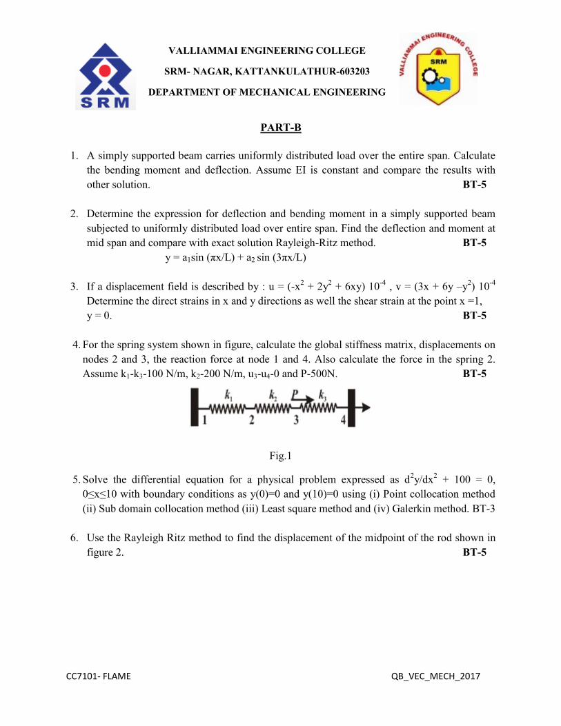
4. For the spring system shown in figure, calculate the global stiffness matrix, displacements on
nodes 2 and 3, the reaction force at node 1 and 4. Also calculate the force in the spring 2.
Assume k1-k3-100 N/m, k2-200 N/m, u3-u4-0 and P-500N. BT-5
Fig.1
5. Solve the differential equation for a physical problem expressed as d2y/dx
2 + 100 = 0,
0≤x≤10 with boundary conditions as y(0)=0 and y(10)=0 using (i) Point collocation method
(ii) Sub domain collocation method (iii) Least square method and (iv) Galerkin method. BT-3
6. Use the Rayleigh Ritz method to find the displacement of the midpoint of the rod shown in
figure 2. BT-5

CC7101- FLAME QB_VEC_MECH_2017
VALLIAMMAI ENGINEERING COLLEGE
SRM- NAGAR, KATTANKULATHUR-603203
DEPARTMENT OF MECHANICAL ENGINEERING
Fig.2
7. A simply supported beam subjected to uniformly distributed load over entire span and it is
subjected to a point load at the centre of the span. Calculate the deflection using Rayleigh-
Ritz method and compare with exact solutions. BT-5
8. A uniform rod subjected to a uniform axial load is illustrated in figure 3. The deformation of
the bar is governed by the differential equation given below. Determine the displacement
using weighted residual method. BT-5
Fig.3
9. Solve the differential equation for a physical problem expressed as d2y/dx
2 + 50 = 0, 0≤x≤10
with boundary conditions as y (0) = 0 and y (10) = 0 using the trial function y = a1x (10-x)
find the value of the parameters a1 by the following methods. (i) Point collocation method
(ii) Sub domain collocation method (iii) Least squares method and (iv) Galerkin method.
BT-3
10. A Plysical phenomenon is governed by the differentital equation
22
210 = 5
wx
x
for 0≤x≤1.
The boundary conditions are given by w(0) = w(1) = 0. By taking two-term trial solutions as

CC7101- FLAME QB_VEC_MECH_2017
VALLIAMMAI ENGINEERING COLLEGE
SRM- NAGAR, KATTANKULATHUR-603203
DEPARTMENT OF MECHANICAL ENGINEERING
w(x) = c1f1 + c2f2(x) with, f1(x) = x(x-1) and f2 = x2(x-1) find the solution of the problem
using the Galerkin method. BT-3
11. Consider the differential equation d2Φ/dx
2 + 400 x
2 = 0, for 0≤x≤1, subject to boundary
conditions y(0) = 0; y(1) = 0. Find the solution of the problem using Rayleigh-Ritz method.
Take two-term solution as y(x) = c1 x(1-x) + c2 x2 (1-x). BT-5
12. Using any weighted residual methods, find and compare the approximate solutions for the
boundary value problem -(d2u/dx
2) = cos(πx) = 0, for 0≤x≤1 with the boundary conditions
u(0) = 0, and u(1) = 1. BT-5
13. A beam AB of span ‘L’ simply supported at ends and carrying a concentrated load W at the
centre ‘C’. Determine the deflection at mid span by using Rayleigh-Ritz method and compare
with exact solutions. BT-5
14. The following differential equation is available for a physical phenomenon
AE(d2y/dx
2 )+ qo=0 with the boundary conditions y(0)=0, (dy/dx)x=L = 0. Find the value of
f(x) using the weighted residual method. BT-5
PART-C
1. The shape functions for the three noded quadratic element are
N1 = 2/l2 (X-x2) (X-x3), N2 = - 4/l
2 (X-x1) (X-x3) and N3 = 2/l
2 (X-x1) (X-x2)
a) Analysis that these shape functions equal one at their own node and are zero at the
other two nodes. Also show that the shape functions sum to one.
b) Show that the derivatives of N1, N2, and N3 with respect to x sum to zero. BT-4
2. Consider a one-dimensional element (e) represented by 3 nodes 1, 2 and 3 such that node 2
is mid-way of 1 and 3. Assuming a quadratic interpolation for the function, T, Evaluate the 3
shape functions N1, N2 and N3 such that, T = N1T1 + N2T2 + N3T3. Assume the coordinates
X1 = 0, X2 = ½ and X3 = 1 for simplicity. BT-5
3. Compute the value of central deflection for a beam as shown in figure 4. by assuming
y= a sin(πx / L). The beam is uniform throughout and carries a central point load P. BT-5

CC7101- FLAME QB_VEC_MECH_2017
VALLIAMMAI ENGINEERING COLLEGE
SRM- NAGAR, KATTANKULATHUR-603203
DEPARTMENT OF MECHANICAL ENGINEERING
Fig.4
4. Analysis for the tapered bar as shown in Figure 5. subjected to its own self weight,
determine the deflection at the free end using Ritz Technique. Assume E = 200 GPa, and ρ
= 77KN/m3. BT-3
Fig.5
100 x 100
Sq.
40 x 40
Sq.
1000
mm
100
mm

CC7101- FLAME QB_VEC_MECH_2017
VALLIAMMAI ENGINEERING COLLEGE
SRM- NAGAR, KATTANKULATHUR-603203
DEPARTMENT OF MECHANICAL ENGINEERING
UNIT II ONE DIMENSIONAL FINITE ELEMENT ANALYSIS
PART-A
1. Define Shape Function and write down the shape function for one dimensional element?
BT-1
2. Show the shape function of a two noded line element. BT-3
3. Sketch the shape function of a two noded line element with one degree of freedom at each
node. BT-3
4. Plan the shape function for one dimensional line element with three nodes. BT-6
5. State the properties of stiffness matrix. BT-4
6. List out the stiffness matrix properties. BT-1
7. Point out properties of shape functions. BT-4
8. When does the stiffness matrix of a structure become singular? BT-1
9. Name the properties of global stiffness matrix. BT-1
10. Define the term discretization. BT-1
11. Why polynomial terms preferred for shape functions in finite element method? BT-5
12. Distinguish between pane stress and plane strain problems. BT-2
13. Differentiate global and local coordinates. BT-2
14. Write the element stiffness matrix of a truss element. BT-4
15. Solve the load vector for the beam element in figure 6. BT-3
Fig.6
16. Explain sub parametric, isoperimetric and super parametric elements. BT-5
17. State Fourier’s law of heat conduction used in FFA. BT-1
18. Rewrite the role of Jacobian matrix in FEM. BT-6
19. Discuss aspect ratio of elements. What are its effects? BT-2
20. Describe plane stress problem with a suitable example. BT-2
PART-B
1. A steel rod of length 1m is subjected to an axial load of 5kN as shown in Figure 7. Area of
cross section of the rod is 250mm2. Using 1D element equation solve for the deflection of
the bar E = 2 x 10⁵ N/mm
2. Use four elements. BT-3

CC7101- FLAME QB_VEC_MECH_2017
VALLIAMMAI ENGINEERING COLLEGE
SRM- NAGAR, KATTANKULATHUR-603203
DEPARTMENT OF MECHANICAL ENGINEERING
Fig.7 Fig.8
2. Consider a bar as shown in Figure 8. Young’s Modulus E = 2 x 10⁵ N/mm
2. A1 = 2cm
2, A2 =
1cm2 and force of 100N. Determine the nodal displacement. BT-5
3. Consider the bar shown in figure Axial force P =30 KN is applied as shown figure 9.
Determine the nodal displacement, stresses in each element and reaction forces. BT-5
Fig.9
4. Axial load of 500N is applied to a stepped shaft, at the interface of two bars. The ends are
fixed. Evaluate the nodal displacement and stress when the element is subjected to all in
temperature of 100ºC. Take E1 = 70 x 103 N/mm2, E2 = 200 x 103 N/mm
2, A1 = 900mm
2, A2
= 1200mm2, α1 = 23 x 10
-6 / ºC, α2 = 11.7 x 10
-6 / ºC L1 = 200mm, L2 = 300mm. BT-5
5. For the beam and loading as shown in figure 10. Determine the slopes at the two ends of the
distributed load and the vertical deflection at the mid-point of the distributed load. Take
E=200 GPa. And I=4X106 mm
4. BT-5
Fig.10
12KN/m
1 m 1 m

CC7101- FLAME QB_VEC_MECH_2017
VALLIAMMAI ENGINEERING COLLEGE
SRM- NAGAR, KATTANKULATHUR-603203
DEPARTMENT OF MECHANICAL ENGINEERING
6. Determine the displacements and slopes at the nodes for the beam shown in figure. Find the
moment at the midpoint of element 1. BT-5
Fig.11
7. Determine the force in the members of the truss as shown in figure 12. Take E=200GPa.
BT-5
Fig.12
8. The loading and other parameters for a two bar truss element is shown in figure 13.
Determine (i) The element stiffness matrix for each element (ii) Global stiffness matrix (ii)
Nodal displacements (iv) Reaction Force (v) The stresses induced in the elements. Assume
E=200GPa. BT-5
Fig.13
CC7101- FLAME QB_VEC_MECH_2017
VALLIAMMAI ENGINEERING COLLEGE
SRM- NAGAR, KATTANKULATHUR-603203
DEPARTMENT OF MECHANICAL ENGINEERING
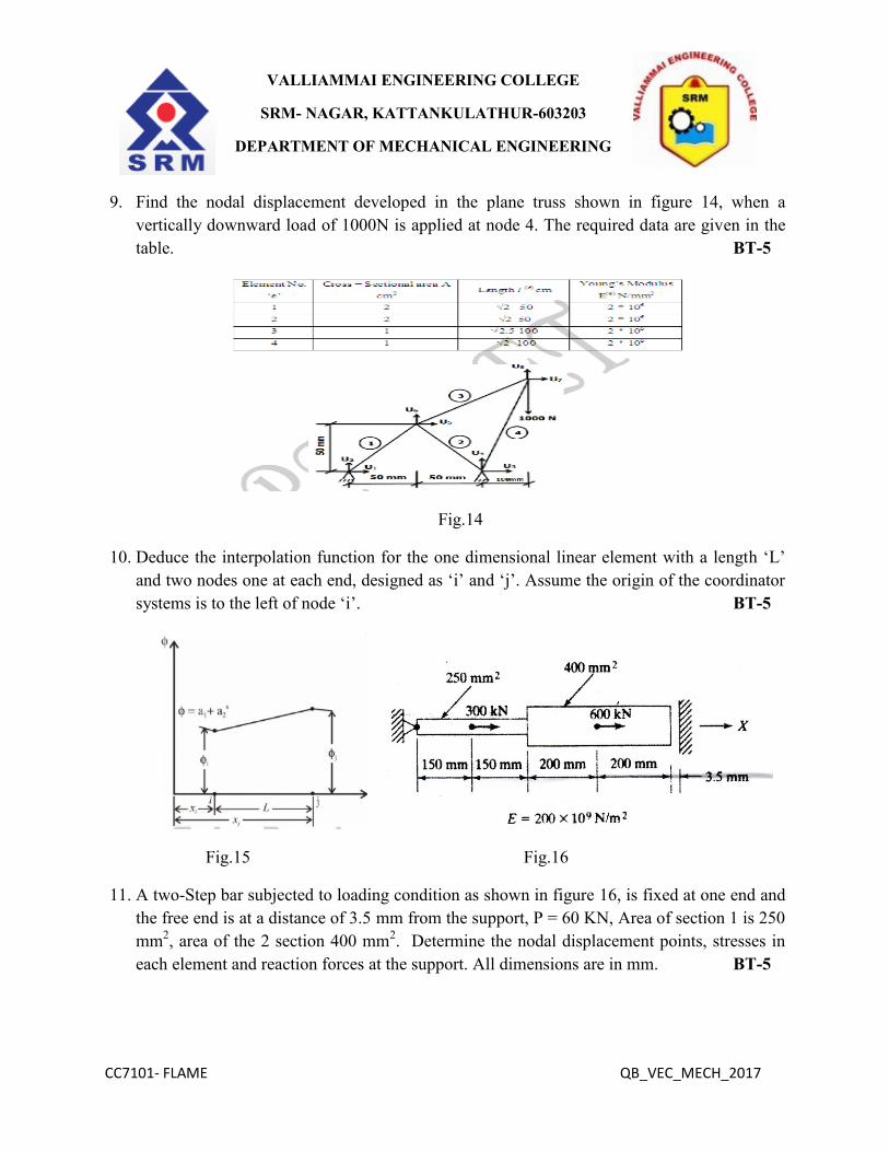
9. Find the nodal displacement developed in the plane truss shown in figure 14, when a
vertically downward load of 1000N is applied at node 4. The required data are given in the
table. BT-5
Fig.14
10. Deduce the interpolation function for the one dimensional linear element with a length ‘L’
and two nodes one at each end, designed as ‘i’ and ‘j’. Assume the origin of the coordinator
systems is to the left of node ‘i’. BT-5
Fig.15 Fig.16
11. A two-Step bar subjected to loading condition as shown in figure 16, is fixed at one end and
the free end is at a distance of 3.5 mm from the support, P = 60 KN, Area of section 1 is 250
mm2, area of the 2 section 400 mm
2. Determine the nodal displacement points, stresses in
each element and reaction forces at the support. All dimensions are in mm. BT-5

CC7101- FLAME QB_VEC_MECH_2017
VALLIAMMAI ENGINEERING COLLEGE
SRM- NAGAR, KATTANKULATHUR-603203
DEPARTMENT OF MECHANICAL ENGINEERING
12. A wall of 0.6 m thickness having thermal conductivity of 1.2 W/m-K. The wall is to be
insulated with a material of thickness 0.06 m having an average thermal conductivity of 0.3
W/m-K. The inner surface temperature is 1000˚C and outside of the insulation is exposed to
atmospheric air at 30˚C with heat transfer coefficient of 35 W/m2K. Calculate the nodal
temperatures. BT-5
13. A steel rod of diameter d = 2 cm, length L = 5 cm and thermal conductivity k = 50 W/m˚C is
exposed at one end to a constant temperature of 320˚C. The other end is in ambient air of
temperature 20˚C with a convection coefficient of h = 100 W/m2C. Determine the
temperature at the midpoint of the rod. BT-5
14. Calculate the temperature distribution in a one dimension fin with physical properties. The
fin is rectangular in shape and is 120 mm long, 40 mm wide and 10 mm thick. Assume that
convection heat loss occurs from the end of the fin. Use two elements Take k= 0.3W/mm˚C;
h = 1 x 10⁻³
W/mm2˚C; Wall Temperature Tw = 120˚C; Tα = 20˚C. BT-5
PART – C
1. Analyze the frame problems as shown in Figure 17. give (a) the transformed element
matrices; (b) the assembled element matrices; and (c) the condensed matrix equations for the
unknown generalized displacements and forces. Use the sign conventions shown in the
figure below for global and element displacement (and force) degrees of freedom. BT-4
Fig.17

CC7101- FLAME QB_VEC_MECH_2017
VALLIAMMAI ENGINEERING COLLEGE
SRM- NAGAR, KATTANKULATHUR-603203
DEPARTMENT OF MECHANICAL ENGINEERING
2. A steel rod of diameter D = 0.02 mm, length L = 0.05 m and thermal conductivity K = 50
W/m C) is exposed to ambient air at T = 20C with a heat transfer coefficient β = 100 W/m2
C). The left end of the rod is maintained at temperature T0 320 C and the other end insulated.
We wish to evaluate the temperature distribution and the heat input at the left end of the rod.
The governing equation of the problem is the same as
Fig.17 BT-5
3. Analysis the element stiffness matrix for a triangular element shown in figure 18. under
plane strain condition. Assume the following data: E = 150 GPa, µ = 0.3 and t = 1 mm.
BT-4
Fig.18 Fig.19

CC7101- FLAME QB_VEC_MECH_2017
VALLIAMMAI ENGINEERING COLLEGE
SRM- NAGAR, KATTANKULATHUR-603203
DEPARTMENT OF MECHANICAL ENGINEERING
4. A Composite wall, made up of different materials, is shown in the Figure 19. The
temperature on the left and right faces are maintained at constant values of 100˚F and 70˚F,
respectively. Find the temperature distribution in the wall using a linear finite element for
each of the two materials. BT-5
Unit III -TWO DIMENSIONAL FINITE ELEMENT ANALYSIS
PART-A
1. State geometric Isotropy. BT-1
2. Rewrite the Lagrange shape functions for a 1D, 2 noded elements. BT-6
3. Discuss 3 noded triangular elements called as a CST element? BT-2
4. List out the interpolation function of a field variable for three-node triangular element.
BT-1
5. Define CST element. BT-1
6. Sketch the shape functions of a CST element. BT-3
7. Explain CST and LST elements. BT-5
8. Differentiate CST and LST elements. BT-4
9. Evaluate the following area integral for the three node triangular element.
∫NiNj2Nk
3 dA BT-5
10. A triangular element is shown in figure 20 and the nodal coordinates are expressed in mm.
Calculate the strain displacement matrix. BT-3
Fig.20
11. Express the nodal displacement equations for a two dimensional triangular elasticity
element. BT-2
12. Formulate the strain displacement relation. BT-6

CC7101- FLAME QB_VEC_MECH_2017
VALLIAMMAI ENGINEERING COLLEGE
SRM- NAGAR, KATTANKULATHUR-603203
DEPARTMENT OF MECHANICAL ENGINEERING
13. State whether plane stress or plane strain elements can be used to model the following
structures. Justify you answer. BT-1
a. A wall subjected to wind load.
b. A wrench subjected to a force in the plane of the wrench.
14. Deduce a 3D problem into a 2D problem. BT-5
15. Derive the jacobian for the one dimensional 2 noded linear element. BT-2
16. Explain the situations where the axisymmetric formulation can be applied. BT-4
17. Express the shape function of four node quadrilateral elements. BT-2
18. Show the transformation for mapping x-coordinate system into a natural coordinate system
for a linear spar element and for a quadratic spar element. BT-3
19. Define Isoparametric elements with suitable examples. BT-1
20. Point out the significance of Jacobian transformation. BT-4
PART-B
1. Develop the element strain displacement matrix and element stiffness matrix of a CST
element. BT-6
2. A two noded line element with one translational degree of freedom is subjected to uniformly
varying load of intensity P1 at node 1 and P2 at node 2. Evaluate the nodal load vector using
numerical integration. BT-5
3. The (x,y) coordinates of nodes i, j and k of a triangular elements are given by (0,0), (3,0) and
(1.5,4) mm respectively. Evaluate the shape functions N1, N2 and N3 at an interior point P (2,
2.5) mm for the element. For the same triangular element, obtain the strain-displacement
relation matrix B. BT-5
4. Consider the triangular element show in figure 21. The element is extracted from a thin plate
of thickness 0.5 cm. the material is hot rolled low carbon steel. The Nodal coordinates are xi
= 0, yi = 0, xj = 0, yj = -1 and xk = 0, yk = -1cm. determine the elemental stiffness matrix.
Assuming plane stress analysis. Take μ=0.3 and E= 2.1 x 10⁷ N/cm
2. BT-5

CC7101- FLAME QB_VEC_MECH_2017
VALLIAMMAI ENGINEERING COLLEGE
SRM- NAGAR, KATTANKULATHUR-603203
DEPARTMENT OF MECHANICAL ENGINEERING
Fig.21 Fig.22
5. Deduce the global stiffness matrix for the plate shown in figure 22. Taking two triangular
elements. Assume plane stress condition. BT-5
6. Develop the element force vector when linearly varying pressure acts on the side joining
nodes jk of triangular element shown in figure 23 and body force of 25N/mm2 acts
downwards. Thickness = 5mm. BT-6
Fig.23 Fig.24
7. Calculate nodal displacement and elemental stresses for the truss shown in figure 24.
E=70GPa cross-sectional area A=2cm2 for all truss members. BT-3
8. Develop the stress-strain relationship matrix (D) for the axisymmetric triangular element.
BT-6

CC7101- FLAME QB_VEC_MECH_2017
VALLIAMMAI ENGINEERING COLLEGE
SRM- NAGAR, KATTANKULATHUR-603203
DEPARTMENT OF MECHANICAL ENGINEERING
9. Evaluate the stiffness matrix for the axisymmetric element shown in figure 25, take E as 2.1
x 106 N/mm
2 and Poisson’s ratio as 0.3. BT-5
Fig.25
10. Deduce the shape function of a nine node quadrilateral Isoparametric element. BT-5
11. The Cartesian coordinates of the nodes of an axi-symmetric triangular element are 1(0,0),
2(50,0) and 3(0. 50). Determine strain displacement matrix. If the nodal displacement are
u1 = 0.05 mm w1 = 0.03, u2 = 0.02mm w2 = 0.02mm, u3 = 0.00 mm w3 = 0.00 mm.
Determine the element stresses. Take E = 210 GPa and Poisson’s ratio = 0.25. BT-5
12. Evaluate the shape functions N1, N2 and N3 at the interior point ‘P’ for the triangular
element shown in the Figure 26. BT-5
Fig.26 Fig.27
13. The nodal coordinators for an axisymmetric triangular element shown in Figure 27 are given
above. Calculate the strain-displacement matrix for that element. BT-5
5, 8
8, 5 3, 4
4.5, 6
CC7101- FLAME QB_VEC_MECH_2017
VALLIAMMAI ENGINEERING COLLEGE
SRM- NAGAR, KATTANKULATHUR-603203
DEPARTMENT OF MECHANICAL ENGINEERING
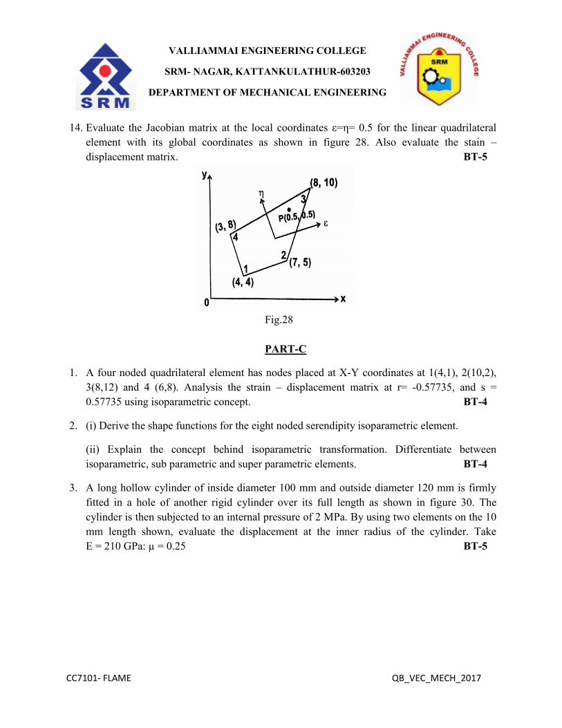
14. Evaluate the Jacobian matrix at the local coordinates ε=η= 0.5 for the linear quadrilateral
element with its global coordinates as shown in figure 28. Also evaluate the stain –
displacement matrix. BT-5
Fig.28
PART-C
1. A four noded quadrilateral element has nodes placed at X-Y coordinates at 1(4,1), 2(10,2),
3(8,12) and 4 (6,8). Analysis the strain – displacement matrix at r= -0.57735, and s =
0.57735 using isoparametric concept. BT-4
2. (i) Derive the shape functions for the eight noded serendipity isoparametric element.
(ii) Explain the concept behind isoparametric transformation. Differentiate between
isoparametric, sub parametric and super parametric elements. BT-4
3. A long hollow cylinder of inside diameter 100 mm and outside diameter 120 mm is firmly
fitted in a hole of another rigid cylinder over its full length as shown in figure 30. The
cylinder is then subjected to an internal pressure of 2 MPa. By using two elements on the 10
mm length shown, evaluate the displacement at the inner radius of the cylinder. Take
E = 210 GPa: µ = 0.25 BT-5

CC7101- FLAME QB_VEC_MECH_2017
VALLIAMMAI ENGINEERING COLLEGE
SRM- NAGAR, KATTANKULATHUR-603203
DEPARTMENT OF MECHANICAL ENGINEERING
Fig.30
4. Evaluate the eigenvalues and eigenvectors of a problem BT-5
1 -2 2 0
X = λ X
-2 1 0 2
Use generalized Jacobi method. Take E = 200GPa, weight density 7850 Kg/ m3,I = 400 mm
4
and A = 300 mm2.
Unit IV ANALYSIS OF PRODUCTION PROCESSES
PART - A
1. Define incrementation. BT-1
2. Discuss time stepping process. BT-2
3. Specify the different methods of generation of mesh. BT-3
4. Explain chip separation. BT-4
5. Sketch some 1D, 2D and 3D finite elements. BT-1
6. Define the team flow formulation. BT-1
7. State the various types of non-linearity. BT-1
8. Explain discrete model. BT-5
9. Distinguish between solid formulation and flow formulation. BT-2
10. Define gap element. BT-1
11. Summarize gap element techniques. BT-2
12. Illustrate the types of dynamic analysis problems. BT-3
13. Define normal modes. BT-1
14. Point out Coulomb function. BT-5
15. Prepare constant Shear stress function. BT-6
16. Differentiate shear in stricking Zone and Sliding Zone. BT-4

CC7101- FLAME QB_VEC_MECH_2017
VALLIAMMAI ENGINEERING COLLEGE
SRM- NAGAR, KATTANKULATHUR-603203
DEPARTMENT OF MECHANICAL ENGINEERING
17. Describe Finite element software packages. BT-2
18. Name application of Software packages. BT-1
19. Formulate the steps followed in Nicholson algorithm. BT-6
20. Explain work bench modeling. BT-4
PART-B
1. Develop the equilibrium equations governing the behavior of the stress components in a
solid when the point is in the interior of the body. BT-6
2. Explain how the Nicholson algorithm is used in the prediction of grain structure. BT-5
3. Explain the finite element analysis procedural steps pertaining to metal casting of a
cylindrical body incorporating the necessary boundary conditions. BT-5
4. Explain the concepts of plasticity in manufacturing engineering. BT-5
5. Develop Lagrangian and Eulerian formulation of solid mechanics problems. BT-6
6. Examine in details adaptive mesh generation procedure. BT-3
7. Explain the grains structure and explain methods of grains formation methods. BT-5
8. Illustrate in details time stepping procedure for metal cutting operation. BT-3
9. How the chip separation criteria are fixed? Detail below. BT-4
10. Describe how to model and simulate the process of metal cutting process and discuss the
potential benefits of FEA for reducing the number of iterations and results in a substantial
cost savings. BT-2
11. Describe finite element analysis of metal casting to obtain temperature distribution and
stress distribution. BT-2
12. Connect finite element modelling and analysis of metal cutting process with appropriate
sketch. BT-4
13. With neat sketch briefly explain mechanism of chip formation in machining of brittle
materials. BT-3
14. Explain the various solution technique for non-linear analysis and list the relative merits and
demerits of each technique. BT-3
PART-C
1. Consider the cantilever beam (E = 30 x 106 psi, V = 0.25, a = 10 in, b = 2 in, h = 1 in) as
shown in Figure 31. We wish to evaluate using the elasticity equations, the maximum
deflection and bending stress in the beam when it is subjected to a uniformly distributed
shear stress τo = 150 psi. The boundary conditions of the problems are BT-5

CC7101- FLAME QB_VEC_MECH_2017
VALLIAMMAI ENGINEERING COLLEGE
SRM- NAGAR, KATTANKULATHUR-603203
DEPARTMENT OF MECHANICAL ENGINEERING
Fig.31
2. Analyze the SDT (shear deformation plate theory) in a rectangular plate. BT-4
3. To analysis FEA of the metal cutting process in lathe machine with suitable examples BT-4
4. Evaluate the grain structure in metal casting process with neat sketch. BT-5
Unit V - COMPUTER IMPLEMENTATION
PART-A
1. List some of the requirement to produce a valid mesh. BT-1
2. Explain node and elements in details. BT-5
3. Select material section in Ansys. BT-5
4. Discuss types of boundary condition. BT-2
5. Name the few finite element packages. BT-1
6. Estimate how to develop codes in Ansys. BT-2
7. Define grid generation. BT-1
8. List out list of grid generation methods. BT-1
9. Explain how to give input condition of materials in ANSYS. BT-5
10. List out types of work bench. BT-1
11. Discuss why the tools are included in work bench. BT-2
12. List the source of nonlinearity in welding problem. BT-1
13. Specify how the following boundary conditions are treated in finite element analysis of
forming process. 1) Die work piece interface, 2) Rigid work piece. BT-4
14. Distinguish between pre-processor and post-processor in finite element computations.
BT-2
15. Prepare the steps followed in ANSYS software for finite element analysis. BT-6

CC7101- FLAME QB_VEC_MECH_2017
VALLIAMMAI ENGINEERING COLLEGE
SRM- NAGAR, KATTANKULATHUR-603203
DEPARTMENT OF MECHANICAL ENGINEERING
16. Discover how the Plasticity of the material defined in any FEA commercial preprocessor
can. BT-3
17. Define the stream function for a one-dimensional incompressible flow. BT-1
18. Classify the method of describing the motion of fluid. BT-3
19. State the relation between the velocity of fluid flow and the hydraulic gradient according to
Darcy’s law, explaining the terms involved. BT-2
20. Explain the stream function for a two dimensional incompressible flow. BT-5
PART-B
1. Explain the following:
a. Mesh generation process (6)
b. Application on ANSYS in fluid flow analysis. (7) BT-4
2. Grade the method of code generation for a one dimensional heat transfer problem. BT-5
3. Define is element connectivity? And explain in details. BT-1
4. Describe how mesh generation is done using Delaunay’s triangulation technique. BT-4
5. Briefly explain pre-processing of ANSYS fluent software. BT-2
6. How to extract the result from ANSYS software with post processing explains in details.
BT-2
7. Develop the methods of coding in one dimensional analysis and two dimensional analyses.
BT-6
8. Explain in details boundary condition implementation on ANSYS software package. BT-4
9. Describe in detail, how mesh generation is done using Region based approach. BT-2
10. Illustrate how many methods involved in transferring work in the finite element analysis
packages? Explain any five in details. BT-3
11. Discuss the following with the help of ANSYS package. BT-2
(i) Meshing of a plate with hole.
(ii) p-refinement and h-refinement
(iii) Applying boundary condition
12. Write down the pre-processing and post-processing stages in ANSYS for solving a
cantilever beam with a point load at the end. BT-3
13. Write a finite element code in the programming language of your choice to find out the
circumference of a circle. BT-3
14. Discuss the following with suitable examples: BT-2
a. Geometric Nonlinearity
b. Material Nonlinearity
c. Problems of Gaps and Contact.

CC7101- FLAME QB_VEC_MECH_2017
VALLIAMMAI ENGINEERING COLLEGE
SRM- NAGAR, KATTANKULATHUR-603203
DEPARTMENT OF MECHANICAL ENGINEERING
PART.C
1. Evaluate the heat transfer in a rod. The problem is governed be where θ is the non-
dimensional temperature and L, m2 , θo , k, and β are give L = 0.05 m, m
2 = 400 m
2 ,
θo=300 ˚C , β = 100 W/cm2, k = 50 W/m˚C. BT-5
2. We consider the three-member plane truss as shown in fig. A plane truss problem falls into
MODEL = 4 and NTYPE = 0. To obtain the solution in no dimensional from, we take E= 1,
A = 1, P=1 and L =1. The data are discontinuous (ICONT = 0). The input and partial output
are presented. BT-5
3. To develop code of one dimensional analysis in metal cutting process. BT-6
4. To analysis the Preprocess, processor and post processor of DEFORM software in details.
BT-4