cclliippppe err oiillsseeaallss innttrroodduuccttiioonn cclliippppe err®oiillsseeaallss catalog eps...
TRANSCRIPT

5
CClliippppeerr®® OOiill SSeeaallssCatalog EPS 5350/USA
5-1 Parker Hannifin CorporationEPS Division
Toll Free: (800) 233-3900www.parkerseals.com
IInnttrroodduuccttiioonnContentsEngineering . . . . . . . . . . . . . . . . . 5-3Materials . . . . . . . . . . . . . . . . . . . 5-6Product Offering . . . . . . . . . . . . . 5-9
Part NumberingNomenclature . . . . . . . . . . . . . 5-9
Solid Clipper Oil SealsLUP, LPD, LDS Profiles. . . . . . 5-14LUPW, LPDW, LDSWProfiles . . . . . . . . . . . . . . . . . . 5-15HP, MP Profiles. . . . . . . . . . . . 5-16OL Profile . . . . . . . . . . . . . . . . 5-17ST-LUP, ST-LPD Profiles . . . . . 5-18TSS Profile . . . . . . . . . . . . . . . 5-19DL Profile . . . . . . . . . . . . . . . . 5-20RPDT Profile . . . . . . . . . . . . . 5-21P, H Profiles . . . . . . . . . . . . . . 5-22SS, SDS Profiles . . . . . . . . . . 5-23Clipper Sliptite Profile . . . . . . . 5-24TMAL, TMAS Profiles . . . . . . . 5-25MIST, LifeLine Profile . . . . . . . 5-26RUP, RPD Profiles . . . . . . . . . 5-27
Split Clipper Oil Seals . . . . . . . . . 5-28
Clipper Oil Seal
OEMs worldwide know Clipper Oil Seals for their ability toprovide superior performance in the most demanding andcritical applications. A one-piece molded construction and theability to provide application-specific designs, if needed, arejust a few of the reasons Clipper seals are specified forcritical applications. These applications include as aircraftlanding gear, military vehicles, underground mining equip-ment and roll chocks used in the steel industry.
Clipper seals are available for shaft diameters from0.250" (6.35 mm) to over 65" (1651 mm) in both standard andhigh performance elastomer compounds. With over 10,000tooled sizes, Clipper seals are readily available for mostapplications in either a solid or split design.
The most unique feature of the Clipper oil seal isnonmetallic construction. The metal case that is common withtraditional lip seals is replaced with an aramid fiber andelastomer composite material.
A wide range of lip profiles are available with the aramidcomposite OD to suit virtually any application need. Forstandard profiles, see Table 5-7 on Page 5-10.
Stainless Steel Springs Are Standard on all Clipper OilSeals where the industry standard is a lower quality carbonsteel. Clipper’s spring material provides improved lip loadingat higher temperatures and resists the rust and corrosionthat is common with lower quality materials. The upgradedspring ensures consistent lip loading over the life of the seal.
03/28/06
Clipper Oil Seals provide superiorperformance in the mostdemanding and criticalapplications.
BleedsPg72to122.indd 1 4/10/2006 1:28:01 PM
www.comoso.com

5
Introduction Clipper® Oil Seals
5-2 Parker Hannifin CorporationEPS Division
Toll Free: (800) 233-3900www.parkerseals.com
Catalog EPS 5350/USA
ApplicationsClipper Oil Seals are used in a wide range of
industries including light industrial, mining, paper,steel, food processing, marine, aerospace andpetrochemical.
Application equipment includes:
• Pumps• Motors• Gearboxes• Crushers• Fans• Pillow blocks• Runout tables• Paper rolls• Work rolls• Mixers• Compressors• Overhead cranes• Drag lines• Hoists• Elevators• Mine cart wheels• Flywheels• Idler wheels• Tapered bearings• Custom equipment
Features, Advantages and BenefitsThe Clipper Oil Seal can be used as a direct
replacement for metal case seals and provides thefollowing benefits:
1. Composite OD provides gasket-type seal atOD for improved sealing in worn housings.Compression plates are not required for sealretention or lip loading. The tight press fiteliminates the need for a cover plate.
2. Will not rust or corrode.
3. Consists of a seal lip and seal OD to form aone-piece molded construction across entire sizerange and a more robust design compared togluing or crimping the seal lip to a metal case.
4. Resists problems caused by thermalexpansion when seal case and housing aredifferent materials.
5. Eliminates seal damage during installation.The Clipper seal is known for its user-friendlyinstallation.
6. Nonmetallic construction allows splitabledesign.
7. Composite material provides unique designcapabilities; i.e. flange, buttons, mounting holes.
8. Allows for faster delivery of non-stock itemswith no manufacturing delays caused by waiting onmetal components. Seals 14" and over ship inunder 10 days and typically less than four weeks for small diameter.
03/03/06
BleedsPg72to122.indd 2 4/10/2006 1:28:02 PM
www.comoso.com

5
CClliippppeerr®® OOiill SSeeaallssCatalog EPS 5350/USA
5-3 Parker Hannifin CorporationEPS Division
Toll Free: (800) 233-3900www.parkerseals.com
EEnnggiinneeeerriinnggShaft Recommendations
Material — Parker recommends ashaft material of carbon steel with aminimum hardness of Rockwell C30(30 Rc). Soft materials such as bronze,aluminum or plastic should be avoidedbecause they are susceptible togrooving and will cause premature sealfailure. If a soft shaft material must beused, a Parker Quick Sleeve or ParkerWear Sleeve can be installed over thesoft shaft material to provide a durablesealing surface. See Section 7 for details.
Shaft Finish — Parker recommendsa plunge ground finish of 8 to 17 μin Ra(0.20 to 0.43 μm Ra) with zero lead. Ashaft finish significantly smoother orrougher will shorten the service life ofthe seal. For additional information onshaft finish refer to Page 2-6.
Shaft Profile — The shaft profileshould include a lead-in chamfer perthe following example. The leadingedge helps prevent lip roll-back andspring dumping. The leading edge andtrailing edges should be free of burrs orsharp edges that could cut the contactpoint of the seal lip. See Table 2-2aon Page 2-8 for recommended minimum chamfer length.
Figure 5-1. Shaft Profile
Shaft Tolerance — To ensure the proper lip-to-shaftinterference is maintained, shaft diameters should fall withinthe tolerances specified in Tables 5-1 and 5-2. Shaftssignificantly over the tolerance will increase the underliptemperatures and lead to premature failure. An undersizedshaft compromises the amount of lip interference availableto maintain a positive seal.
Table 5-1. Shaft Tolerance for Inch/Fractional
Shaft Diameter ToleranceUp to 4.000" ±.003"
4.001 – 6.000" ±.004"
6.001 – 10.000" ±.005"
Over 10.000" ±.006"
Table 5-2. Shaft Tolerance for Metric*
Shaft Diameter ToleranceUp to 10 mm +0 to -.09 mm
Over 10 – 18 +0 to -.11 mm
Over 18 – 30 +0 to -.13 mm
Over 30 – 50 +0 to -.16 mm
Over 50 – 80 +0 to -.19 mm
Over 80 – 120 +0 to -.22 mm
Over 120 – 180 +0 to -.25 mm
Over 180 – 250 +0 to -.29 mm
Over 250 – 315 +0 to -.32 mm
Over 315 – 400 +0 to -.36 mm
Over 400 – 500 +0 to -.40 mm
*ISO Standard 286-2, h11
03/28/06
30°
At 30°
w See Table 2-2a, Page 2-8 for chamfer length
BleedsPg72to122.indd 3 4/10/2006 1:28:03 PM
www.comoso.com

5
reppilCgnireenignE ® Oil Seals
5-4 Parker Hannifin CorporationEPS Division
Toll Free: (800) 233-3900www.parkerseals.com
Catalog EPS 5350/USA
Housing RecommendationsMaterial — The most commonly used
materials for seal housings are steel and cast iron.Care must be taken when softer housing materialssuch as aluminum, bronze or plastic are used.
Housing Finish — A finish range of 40 to100 μin Ra (1.0 to 2.5 μm Ra) is recommended. TheClipper seal is more tolerant of housing finishesthat are toward the upper limit than metal ODseals.
Housing Profile — A lead-in chamfer per thefollowing example is highly recommended for allseal housings. The chamfer aligns the seal duringinstallation and helps prevent the seal fromcocking. Both corners of the chamfer should befree of burrs and sharp edges to eliminate ODdamage during installation.
Figure 5-2. Housing Profile
Housing Tolerance — The diametricaltolerance of the housing for Clipper Oil Sealsshould be within the limits specified below.
15 to 30°
Bore Chamfer
0.060 to 0.090" (1.5 to 2.2 mm)
Table 5-3. Housing Tolerance for Inch/Fractional
BoreDiameter
DiameterTolerance
H1
DiameterTolerance
STH1
DepthTolerance
(-0/+)Up to 5.9 ±.002 ±.002 +.031
6.0 – 15.9 ±.005 ±.002 +.062
16.0 – 30.9 ±.008 ±.005 +.062
Over 31.0 ±.010 ±.005 +.062
Table 5-4. Housing Tolerance for Metric
BoreDiameter
DiameterTolerance
H1
DiameterTolerance
STH1
DepthTolerance
(-0/+)Up to 150.0 ±.05 ±.05 +.8
151 – 403 ±.13 ±.05 +1.5
404 – 785 ±.20 ±.13 +1.5
Over 786 ±.25 ±.13 +1.5
03/28/06
BleedsPg72to122.indd 4 4/10/2006 1:28:03 PM
www.comoso.com

5
Clipper® gnireenignEslaeSliOCatalog EPS 5350/USA
5-5 Parker Hannifin CorporationEPS Division
Toll Free: (800) 233-3900www.parkerseals.com
Solid Clipper Seal Installation
1. Clean seal bore and shaft. Remove allburrs and nicks.
2. Pre-lubricate theseal ID and shaft beforeinstalling the seal into thecavity. Use a pre-lube thatis compatible with thesystem lubricant. The pre-lube will make the sealeasier to install and prevent dry running duringinitial start-up. (Do not lubricate the seal OD orhousing.)
3. Protect seal lipagainst damage from sharpkeyways, splines and screwthreads. This can be doneby either taping the keyway,inserting an element intothe keyway or using anassembly sleeve that fits over the shaft.
4. Point seal lip incorrect direction and pushto edge of the counterbore.
5. Start seal into cavityby finger pressure. Afterstarting seal in housing,tap evenly with a soft-faced mallet all around untilseated.
6. Finish installation byusing a flat plate tool todrive seal in final position.The plate diameter shouldbe large enough so itcontacts the face of sealhousing. This will ensureseal is positioned straight and perpendicular to theshaft.
Split (R Series) Clipper Seal Installation
1. Clean the equipmentcavity recess areathoroughly. Remove allburrs and sharp corners.Provide adequate lead-inchamfers.
2. Apply light grease or oil coating to the shaftarea where the lip will engage. Do not apply grease or oil to seal OD or equipment bore surface.
3. Separate the cutends of the seal sidewaysso that seal forms a helix.Do not try to form the sealinto a “U” shape. Separateends far enough so that theseal can be slipped overthe shaft.
4. Insert the garterspring over the shaft,between the seal and thebore cavity, connecting theends of the spring with thehook-and-eye connectors.Insert the garter spring intothe lip carrier groove with the connection at least45° from the split juncture. Push the seal towardthe bore cavity until it touches, making sure that the split ends are well aligned and positioned at 12 o’clock.
5. Start inserting theseal into the cavity with thesplit juncture at top,compressing the ODslightly, until the splitjuncture has been insertedto about one-third of itswidth. Continue pressing the balance of the sealinto the cavity, working away from the split, untilthe entire seal has been started into the cavityrecess. Tap evenly around the back face of theseal with a soft-faced mallet until it is completelyseated.
6. Use a flat plate tool that will drive the sealflush with the housing to ensure seal is installedsquare and perpendicular to the shaft.
03/28/06
BleedsPg72to122.indd 5 4/10/2006 1:28:04 PM
www.comoso.com

5
CClliippppeerr®® OOiill SSeeaallssCatalog EPS 5350/USA
5-6 Parker Hannifin CorporationEPS Division
Toll Free: (800) 233-3900www.parkerseals.com
MMaatteerriiaallssCommon Materials Used inthis Product
Clipper Oil Seals are available in awide range of materials. The followinggeneral material descriptions are forthe OD material “H” and correspondinglip material “L”.
OD and Lip Materials
H1L5 & H1L7 — Nitrile (NBR)
Standard Nitrile is the most commonly used polymer in therotary shaft seal industry. NBR has very good resistance tooil, fuel and alkali solutions. Nitrile offers excellent resistanceto petroleum-based hydraulic fluids and is resistant tohydrocarbon solvents. Standard Nitrile has poor resistance toozone, ketones, automotive or aircraft brake fluid, and steamor hot water. Standard Nitrile is recommended for operating intemperatures ranging from -20 to +250 °F (-29 to +121 °C)and offers good mechanical properties and abrasionresistance.
H1L50 & H1L70 — Low Temp Nitrile (NBR)
Nitrile compounds can be formulated for applications inextreme cold weather environments. These specialformulations of Nitrile allow for operation at minimumtemperatures ranging down to -70 °F (-57 °C), whilemaintaining good chemical and abrasion resistance, but theupper temperature limit is lowered to 212 °F (100 °C).
H1L20 — Carboxylated Nitrile (XNBR)
XNBR is formulated to greatly enhance tear and abrasionresistance over standard Nitrile, while maintaining similarchemical compatibility. It is used in applications whereabrasive materials may collect at the point of shaft contact.XNBR is less resilient and flexible at low temperature, andoffers poorer compression set resistance than standardNitrile. Carboxylated Nitriles are recommended for operationat temperatures ranging from -30 to +250 °F (-34 to +121°C).
H1L30 — Hydrogenated Nitrile (HNBR)
Hydrogenated Nitriles offer improved abrasion resistance,excellent chemical resistance and higher operatingtemperatures than standard NBR. Ozone and weatherresistance, as well as resistance to hot water are alsoincreased. HNBR compounds are recommended foroperating temperatures ranging from -40 to +300 °F (-40 to+149 °C).
03/28/06
BleedsPg72to122.indd 6 4/10/2006 1:28:05 PM
www.comoso.com

5
Clipper® slairetaMslaeSliOCatalog EPS 5350/USA
5-7 Parker Hannifin CorporationEPS Division
Toll Free: (800) 233-3900www.parkerseals.com
H1L8 — Neoprene (CR)
Neoprene offers very good resistance to weather,ozone and natural aging as well as good flameresistance while maintaining moderate resistanceto oil and gasoline. Good abrasion, flex andcracking resistance is available with the Neoprenematerial. Neoprene is recommended for operatingtemperatures ranging from -45 to +250 °F (-43 to+121 °C).
H1L21 — Ethylene Propylene (EPDM)
EPDM offers excellent heat, ozone and sunlightresistance. EPDM offers very good lowtemperature flexibility, good resistance to alkalis,acids (such as acetic), and oxygenated solvents(such as MEK). Provides improved resistance towater and steam in applications where NBR andFKM exhibit poor service life. Good replacementfor FKM where solvents are a problem. It is notrecommended for petroleum oil. EPDM isrecommended for operating temperatures of -60 to+300 °F (-51 to +149°C).
H5L16 — Fluoroelastomer (FKM)
FKM provides excellent resistance to oils, fuelsand hydraulic fluids at temperatures that farexceed standard Nitrile. It also has very goodresistance to flame and excellent impermeability togases and vapors. FKM is recommended foroperating temperatures that range from -40 to+400 °F (-40 to +204 °C).
Case Materials
H1, H3 — Neoprene/Aramid Composite
The aramid fiber-reinforced composite shell will fita wide range of bore tolerances and provides arustproof gasket-type seal at the OD. Thecomposite case also will fill slight imperfections inthe bore housing, reducing machining cost.Usually combined with a Nitrile lip material.
H5 — Fluoroelastomer/Aramid Composite
Offers the same construction benefits mentionedabove. Usually combined with a Fluoroelastomerlip material.
Spring MaterialsSprings are available in a wide range of
materials from Parker. Clipper Oil Seal designs arefurnished with 302 stainless steel springs asstandard. Other spring materials are available atan additional cost. Table 5-5 shows generaloperating parameters for the most common springmaterials.
Spring Type
For lip loading, the Clipper Oil seal uses a coilwire spring (garter spring).
Garter spring benefits:
• Provides a more uniform load to sealing lip
• Heat treated — stress relieved
• Constant load with minimum load variations
• Able to adjust the spring in the field toincrease load
Two types of spring connections are used:
1. Threaded type is used on most solid seals.
2. Hook and eye type are used on splits sealsbecause they are easier for the end user toconnect during installation.
Table 5-5. Spring Material Parameters
Wire Type
MaximumService
Temperature Application
°C °F
Carbon Steel 120 250 General purpose
Monel 400 230 450 Saltwater
Inconel 750 675 1250 Extreme temperature
Phosphor Bronze 95 200 Saltwater
302/304 StainlessSteel
260 500 Corrosion resistance
316 StainlessSteel
315 600 Hi-temp corrosionresistance
03/28/06
Hook and Eye
Threaded
BleedsPg72to122.indd 7 4/10/2006 1:28:06 PM
www.comoso.com

5
reppilCslairetaM ® Oil SealsCatalog EPS 5350/USA
5-8 Parker Hannifin CorporationEPS Division
Toll Free: (800) 233-3900www.parkerseals.com
Table 5-6. Clipper Oil Seal Standard MaterialMatl.Code
Case/LipMaterial Description Abrasion
ResistanceMin.
TempCont.Temp
Peak.Temp
F°052F°212F°02-dooGyreV) Standard NBR offering.RBNoruD57(elirtiN5L1H
The NBR lip material has very good resistance to oil and gasoline. Superior resistanceto petroleum based hydraulic fluids. Good resistance to hydrocarbon solvents. Verygood resistance to alkalis and solvents. Poor resistance to oxygenated solvents.
-29 °C 100 °C 121 °C
F°052F°212F°03-dooGyreV)RBNoruD58(elirtiN7L1H
The L7 lip material has a lower minimum temperature capability than the L5 material. -34 °C 100 °C 121 °C
F°052F°212F°03-gnidnatstuO)RBNXoruD38(elirtiNdetalyxobraC02L1H
The XNBR lip material is generally tougher and more resistant to tear and abrasion thanstandard NBR.
-34 °C 100 °C 121 °C
H1L30 Hydrogenated Nitrile (75 Duro F°003F°052F°04-gnidnatstuO)RBNH
The HNBR lip material offers improved abrasion resistance, chemical resistance,higher operating temperature and better ozone resistance than standardNBR.
-40 °C 121 °C 149 °C
F°052F°212F°02-dooGyreV)RBNoruD57(elirtiN5LLLA
Homogenous NBR material without aramid fiber OD provides a very pliable seal that canbe stretched over flanges or other obstructions on the shaft. A cover plate isrecommended to keep the seal retained in the housing bore.
-29 °C 100 °C 121 °C
F°212F°002F°05-dooGyreV)RBNpmeTwoLoruD58(elirtiNcitcrA05L1H
Low temperature Nitrile lip material allows for lower minimumtemperatures while providing good chemical and abrasion resistance.
-46 °C 93 °C 100 °C
F°212F°002F°07-dooGyreV)RBNpmeTwoLoruD57(elirtiNaksalA07L1H
Same characteristics as L50, but softer wit C°001C°39C°75-r minimum temperature range.ewolh
F°004F°523F°04-dooG)MKForuD09(remotsaleoroulF61L5H
FKM lip material offers outstanding resistance to high heat. Excellent resistance to oil,gasoline, petroleum hydraulic fluids and hydrocarbon solvents. Very goodimpermeability to gases and vapors. Very good resistance to flame, weather, oxygen,ozone and sunlight. Very little resistance to oxygenated solvents. Poor tearresistance.
-40 °C 163 °C 204 °C
F°004F°523F°04-dooG)MKForuD09(remotsaleoroulF98L5H
Improved steam resistance. -40 °C 163 °C 204 °C
N/P PTFE bonded to NBR lip — PTFE layer provides improved dry running capability,chemical resistance, and reduces torque consumption.
Very Good -20 °F-29 °C
212 °F100 °C
250 °F121 °C
F°04dooGyreVpilMKFotdednobEFTPP/F-40 °C
325 °F163 °C
400 °F204 °C
H1L21 Ethylene Propylene (75 Duro F°003F°052F°06-dooGyreV)MDPE
Excellent heat, ozone and sunlight resistance. Very good low temperature flexibility,good resistance to alkalis, acids (such as acetic) and oxygenated solvents (such asMEK). Provides improved resistance to water and steam in applications where NBR andFKM exhibit poor service life. Good replacement for FKM where solvents are a problem.
-51 °C 121 °C 149 °C
03/28/06
Not recommended for petroleum oil.
BleedsPg72to122.indd 8 4/10/2006 1:28:06 PM
www.comoso.com

5
CClliippppeerr®® OOiill SSeeaallssCatalog EPS 5350/USA
5-9 Parker Hannifin CorporationEPS Division
Toll Free: (800) 233-3900www.parkerseals.com
PPrroodduucctt OOffffeerriinnggPart Number Nomenclature — Clipper Oil Seals
Solid Seals
English
Metric
Split Seals
English
Metric
03/28/06
H 1 L1 7 6 4 3 5
Mold Number Material Code
H 1 L1 7 6 4 3 5
Mold Number Material Code
M
MetricDimensions
9 8 51 3 2 5 6
Mold NumberShaft SizeExample:1325 = 13.250" Lip Material
Leave blank if NBR V = FKM
1 4 2 8 2
Mold Number
0 2 0 0
Shaft SizeExample:0200 = 200 mm
M
MetricDimensions
Lip Material Leave blank if NBR V = FKM
BleedsPg72to122.indd 9 4/10/2006 1:28:06 PM
www.comoso.com

5
reppilCgnireffOtcudorP ® Oil SealsCatalog EPS 5350/USA
5-10 Parker Hannifin CorporationEPS Division
Toll Free: (800) 233-3900www.parkerseals.com
ProfilesThe following standard Clipper Oil Seal profiles can be used in a wide range of applications for both
MRO and OEM requirements. Parker’s experienced design and engineering teams are available to assistwith standard and custom designs that meet both cost and performance objectives. For traditional metalclad designs, refer to Parker Oil Seals in Section 6..
Table 5-7. Product Profiles
StandardProfiles Features Applications
LUP LPD General purpose spring-loaded single lip seal. Features nonmetallic composite OD for damage-free installation.LPD can be furnished with/without spring retainerfeature.
For oil retention or grease retention. Typicalapplications: electric motors, gearboxes, pumps, fans,runout tables, paper rolls, work rolls, mixers and customequipment.
RUP RPD General purpose spring-loaded single lip seal.Features nonmetallic OD for damage-free installation.Available in solid or split. Splits feature a positive boreretention and require no cover plate.
Splits — for grease retention — with oil, some seepagemay occur. Typical applications: electric motors,gearboxes, pumps, fans, runout tables, paper rolls,mixers, and custom equipment. Split seals are designedfor applications where equipment is unable to bedisassembled due to time constraints.
LUPW LPDW Spring-loaded single lip. Features nonmetalliccomposite OD for damage-free installation.
High runout conditions for applications up to 1"(25.4 mm) total eccentricity. For oil retention and lowspeeds.
LDS General purpose double lip features nonmetalliccomposite OD for damage-free installation. LDS profilehas a primary spring-loaded lip with a non-spring-loaded secondary lip for exclusion of light dust orcontamination.
For oil retention. Excludes light dust and fluid.Typical applications: electric motors, gearboxes,pumps, fans, runout tables, paper rolls, mixers, andcustom equipment.
LDSW High runout conditions up to 0.125" (3.175 mm) totaleccentricity. For oil or grease retention and low speeds.Typical applications: electric motors, gearboxes,pumps, fans, runout tables, paper rolls, mixers, andcustom equipment.
SDS General purpose springless dual lip. Featuresnonmetallic composite OD for damage-free installation.
For grease retention and exclusion of light dust andfluids. Typical light duty applications.
SS General purpose springless single lip seal. Featuresnonmetallic composite OD for damage-free installation.
For grease retention and exclusion of light dust andfluid. Typical light duty applications.
OL Generally used in grease applications where borerotates. Agriculture and ground-engaging equipment.
MIST STMISTw/Buttons
Heavy duty spring-loaded single lip. MIST featuresnonmetallic composite OD for damage-free installation.STMIST features composite OD metal band reinforcedconstruction for absorbing shock load and greater boreretention. Both feature molded-in spring to eliminatespring dumping.
For heavy duty applications. Work rolls, paper rolls,backup rolls and custom equipment.
STLUP STLUPw/Buttons
Spring-loaded single lip with heavy duty metal bandinserted in composite OD. ST design features metalbands for absorbing shock load and greater boreretention. Spacer buttons are available for greasepurging in applications requiring back-to-back sealing.
For heavy duty applications. Work rolls, paper rolls,backup rolls and custom equipment.
03/28/06
Spring-loaded outside lip. Nonmetallic composite ID for tight press fit on shaft. Easy to install.
Specialized double lip features non-metallic composite OD for damage-free installation. Primary lip features molded in spring for lubricant retention. Springless secondary lip for excluding light dust. Floating lip accommodates high misalignment conditions.
BleedsPg72to122.indd 10 4/10/2006 1:28:07 PM
www.comoso.com

5
Clipper® gnireffOtcudorPslaeSliOCatalog EPS 5350/USA
5-11 Parker Hannifin CorporationEPS Division
Toll Free: (800) 233-3900www.parkerseals.com
OperatingTemperature
Range
ShaftSurface Speed
fpm (m/s)
ShaftSize RangeInches (mm)
Maximum ShaftDynamic
Runout (TIR)
Maximum(STBM)
Misalignment
MaximumPressurepsi (bar)
Page
NBR -20 °F to 250 °F-29 °C to 121 °C
FKM -40 °F to 400 °F-40 °C to 204 °C
Up to 3200(16.3)
1/4 – 62.5(6.4 – 1587)
0.010"(0.254 mm)
0.010"(0.254 mm)
0 – 7(0 – 0.48)
Depending onShaft Speed
5-14
NBR -20 °F to 250 °F-29 °C to 121 °C
FKM -40 °F to 400 °F-40 °C to 204 °C
Up to 2000(10.2)
1/2 – 65(13 – 1651)
0.010"(0.254 mm)
0.010"(0.254 mm)
0 – 3(0 – 0.20)
Depending onShaft Speed
5-27
NBR -20 °F to 250 °F-29 °C to 121 °C
FKM -40 °F to 400 °F-40 °C to 204 °C
Up to 1000(5.1)
Speed Depends onRunout
1 – 50(41 – 1270)
0.020 – 1.125"(0.508 – 28.58 mm)
0.020 – 1.125"(0.508 – 28.58 mm)
0 – 7(0 – 0.48)
Depending onShaft Speed
5-15
NBR -20 °F to 250 °F-29 °C to 121 °C
FKM -40 °F to 400 °F-40 °C to 204 °C
Up to 2500(12.7)
3/4 – 25(19 – 635)
0.010"(0.254 mm)
0.010"(0.254 mm)
0 – 7(0 – 0.48)
Depending onShaft Speed
5-14
NBR -20 °F to 250 °F-29 °C to 121 °C
FKM -40 °F to 400 °F-40 °C to 204 °C
Up to 2500(12.7)
Speed Depends onRunout
3/4 – 25(19 – 635)
0.020 – 0.125"(0.508 – 3.175 mm)
0.020 – 0.125"(0.508 – 3.175 mm)
0 – 3(0 – 0.20)
Depending onShaft Speed
5-15
NBR -20 °F to 250 °F-29 °C to 121 °C
FKM -40 °F to 400 °F-40 °C to 204 °C
Up to 2000(10.2)
1/2 – 12.835(12.7 – 326)
0.010"(0.254 mm)
0.010"(0.254 mm)
0 – 7(0 – 0.48)
Depending onShaft Speed
5-23
NBR -20 °F to 250 °F-29 °C to 121 °C
FKM -40 °F to 400 °F-40 °C to 204 °C
Up to 2000(10.2)
1/4 – 6(6.4 – 152)
0.010"(0.254 mm)
0.010"(0.254 mm)
0 – 7(0 – 0.48)
Depending onShaft Speed
5-23
NBR -20 °F to 250 °F-29 °C to 121 °C
FKM -40 °F to 400 °F-40 °C to 204 °C
Up to 1000(5.1)
1 – 65(25 – 1651)
0.010"(0.254 mm)
0.010"(0.254 mm)
0 – 7(0 – 0.48)
Depending onShaft Speed
5-17
NBR -20 °F to 250 °F-29 °C to 121 °C
FKM -40 °F to 400 °F-40 °C to 204 °C
Up to 3200(16.3)
6 – 48(152 – 1219)
0.010"(0.254 mm)
0.010"(0.254 mm)
0 – 7(0 – 0.48)
Depending onShaft Speed
5-26
NBR -20 °F to 250 °F-29 °C to 121 °C
FKM -40 °F to 400 °F-40 °C to 204 °C
Up to 3200(16.3)
5 – 57.875(127 – 1470)
0.010"(0.254 mm)
0.010"(0.254 mm)
0 – 7(0 – 0.48)
Depending onShaft Speed
5-18
03/28/06
BleedsPg72to122.indd 11 4/10/2006 1:28:08 PM
www.comoso.com

5
reppilCgnireffOtcudorP ® Oil SealsCatalog EPS 5350/USA
5-12 Parker Hannifin CorporationEPS Division
Toll Free: (800) 233-3900www.parkerseals.com
Table 5-7. Product Profiles (Continued)
StandardProfiles Features Applications
LifeLine Spring-loaded single lip features heavy duty rubbercovered metal insert. LifeLine features metal insert forabsorbing shock load and greater bore retention.LifeLine features molded-in spring to eliminate springdumping.
For heavy duty applications. Work rolls, paper rolls,backup rolls and custom equipment.
P Features nonmetallic composite OD for damage-freeinstallation. The P wiper scraper lip extends outside thebore face.
Applications for reciprocating service and low speed.
H Features nonmetallic composite OD for damage-freeinstallation. Shallow cavity rod wiper designed forexcluding dust and contamination.
Applications for rotary and reciprocating service.Reciprocating applications may require bore plate.
HP High pressure with a fluoroelastomer sealing element,outer metal case, and a PTFE backup element forpressure. Standard with carbon steel case. Stainlesssteel and other alloys available.
The high pressure (HP) seal is designed to handlerotary and reciprocating motions at high speeds andtemperatures. Typical applications: pumps,compressors and custom equipment.
MP The standard MP is a rubber covered metal design,spring-loaded. Standard profile material FKM, othermaterials available upon request.
MP is typically used in grease and oil retentionapplications. Typical applications: electric motors,gearboxes, pumps, fans, mixers and customequipment.
DL Spring-loaded dual lip seal. Features nonmetalliccomposite OD for damage-free installation.
Dual spring-loaded lips are used when the separation oftwo fluids is required. The design is also used for highcontamination applications in keeping out a dirtyenvironment.
Clipper Sliptite The Clipper Sliptite utilizes a layer of PTFE bonded tothe sealing lip to reduce excessive wearing on the shaftand seal. Features nonmetallic composite OD.
With the PTFE lip the seal can be used in dry runningapplications, at higher speeds, and accepts a broaderrange of chemical compatibility. Typical applications:electric motors, gearboxes, pumps, fans and customequipment.
TMAL TMAS Features a stainless steel outer case. TMAL contains amachined PTFE spring-loaded sealing element. TMAScontains a machined PTFE non-spring-loaded sealingelement.
TMAL & TMAS seals are designed for corrosivechemical service and FDA application.
RPDT Spring-loaded single lip seal. Features tapered heel.Available in splits only.
Pillow blocks.
TSS Features nonmetallic composite OD for damage-freeinstallation. Soft flexible lip provides low friction sealingcontact to give extended service life.
Typical applications: overhead cranes in steel mills,rotary drilling crown and travel blocks, draglines, hoistsand elevators. Also used on mine cart wheels,flywheels, idler wheels and tapered bearings.
03/28/06
BleedsPg72to122.indd 12 4/10/2006 1:28:08 PM
www.comoso.com

5
Clipper® gnireffOtcudorPslaeSliOCatalog EPS 5350/USA
5-13 Parker Hannifin CorporationEPS Division
Toll Free: (800) 233-3900www.parkerseals.com
OperatingTemperature
Range
ShaftSurface Speed
fpm (m/s)
ShaftSize RangeInches (mm)
Maximum ShaftDynamic
Runout (TIR)
Maximum(STBM)
Misalignment
MaximumPressurepsi (bar)
Page
NBR -20 °F to 250 °F-29 °C to 121 °C
FKM -40 °F to 400 °F-40 °C to 204 °C
Up to 3200(16.3)
6 – 48(152 – 1219)
0.010"(0.254 mm)
0.010"(0.254 mm)
0 – 7(0 – 0.48)
Depending onShaft Speed
5-26
NBR -20 °F to 250 °F-29 °C to 121 °C
FKM -40 °F to 400 °F-40 °C to 204 °C
Reciprocating:Up to 300
(1.5)
3/8 – 30(10 – 762)
N/A 0.008"(0.20 mm)
0 5-22
NBR -20 °F to 250 °F-29 °C to 121 °C
FKM -40 °F to 400 °F-40 °C to 204 °C
Rotary:Up to 2000
(10.2)Reciprocating:
Up to 300(1.5)
3/8 – 30(10 – 762)
N/A 0.008"(0.20 mm)
0 5-22
NBR -20 °F to 250 °F-29 °C to 121 °C
FKM -40 °F to 400 °F-40 °C to 204 °C
Up to 4000(20.3)
1/4 – 8(6.4 – 203)
0.003"(0.076 mm)
0.003"(0.076 mm)
300(20)
5-16
NBR -20 °F to 250 °F-29 °C to 121 °C
FKM -40 °F to 400 °F-40 °C to 204 °C
Up to 4000(20.3)
1/4 – 12.500(6.4 – 317)
0.005"(0.127 mm)
0.005"(0.127 mm)
100(7)
5-16
NBR -20 °F to 250 °F-29 °C to 121 °C
FKM -40 °F to 400 °F-40 °C to 204 °C
Up to 2000(10.2)
1/4 – 4(6.4 – 101)
0.010"(0.254 mm)
0.010"(0.254 mm)
0 – 7(0 – 0.48)
Depending onShaft Speed
5-20
NBR -20 °F to 250 °F-29 °C to 121 °C
FKM -40 °F to 400 °F-40 °C to 204 °C
Up to 5000(25.4)
1/2 – 10(12.7 – 254)
0.010"(0.254)
0.010"(0.254 mm)
0 – 7(0 – 0.48)
Depending onShaft Speed
5-24
PTFE -40 °F to 500 °F-40 °C to 260 °C
Up to 2500(12.7)
1/2 – 14(12.7 – 355)
0.006"(0.152 mm)
0.006"(0.152 mm)
0 – 7(0 – 0.48)
Depending onShaft Speed
5-25
NBR -20 °F to 250 °F-29 °C to 121 °C
FKM -40 °F to 400 °F-40 °C to 204 °C
Up to 2000(10.2)
3.375 – 16(85.73 – 406)
0.010"(0.254 mm)
0.010"(0.254 mm)
0 5-21
NBR -20 °F to 250 °F-29 °C to 121 °C
FKM -40 °F to 400 °F-40 °C to 204 °C
Up to 2000(10.2)
1.274 – 17.500(32.36 – 445)
0.010"(0.254 mm)
0.010"(0.254 mm)
0 5-19
03/28/06
BleedsPg72to122.indd 13 4/10/2006 1:28:09 PM
www.comoso.com

5
CClliippppeerr®® OOiill SSeeaallssCatalog EPS 5350/USA
5-14 Parker Hannifin CorporationEPS Division
Toll Free: (800) 233-3900www.parkerseals.com
LLUUPP,, LLPPDD,, LLDDSS PPrrooffiilleess
LUP
LPD
LPD — Spring Retainer
LDS
General Purpose ProfilesLUP/LPD — General purpose spring-loaded single lip
seal. Features nonmetallic composite OD for damage-freeinstallation. LPD can be furnished with/without spring retainerfeature.
LDS — General purpose double lip features nonmetalliccomposite OD for damage-free installation. LDS profile has aprimary spring-loaded lip with a non-spring-loaded secondarylip for exclusion of light dust or contamination.
ApplicationFor oil and grease applications.
Typical applications: electric motors, gearboxes, pumps,fans, runout table, work rolls, paper rolls, mixers and customequipment.
Technical Data
Operating Temperature Range
NBR: -20 to 250 °F (-29 to 121 °C)FKM: -40 to 400 °F (-40 to 204 °C)
Common Materials
NBR – H1L5HNBR – H1L20XNBR – H1L30FKM – H5L16
Shaft Surface Speed
LUP/LPD — Up to 3200 fpm (16.25 m/s)LDS — Up to 2500 fpm (12.7 m/s)
Maximum Pressure
0 to 7 psi (0 to 0.48 bar), depending on shaft speed
Size Range
Available shaft diameter range is 0.375 to 65 inches (10 to1651 mm).
Important: For full listings of standard sizes, see AppendicesB and C.
03/28/06
BleedsPg72to122.indd 14 4/10/2006 1:28:09 PM
www.comoso.com

5
CClliippppeerr®® OOiill SSeeaallssCatalog EPS 5350/USA
5-15 Parker Hannifin CorporationEPS Division
Toll Free: (800) 233-3900www.parkerseals.com
LLUUPPWW,, LLPPDDWW,, LLDDSSWWPPrrooffiilleess
LUPW
LPDW
LDSW
LUPW, LPDW and LDSW ProfilesLUPW/LPDW — Spring-loaded single lip. Features
nonmetallic composite OD for damage-free installation.
LDSW — Specialized double lip features nonmetallic composite OD for damage-free installation. Primary lip featuresmolded-in springs for lubrication retention. Springless secondary lip for excluding light dust. Floating lip accommodates high misalignment conditions.
ApplicationMost commonly used for oil or grease retention where
high shaft misalignment is present. LUPW and LPDWaccommodate misalignment by use of extended lip profileand may require a wider than normal bore depth to avoidinterference of the lip.
Type LDSW accommodates misalignment using ageometry that allows the lip to float with the shaft.
Technical Data
Operating Temperature Range
NBR: -20 to 250 °F (-29 to 121 °C)FKM: -40 to 400 °F (-40 to 204 °C)
Common Materials
NBR – H1L5HNBR – H1L20XNBR – H1L30FKM – H5L16
Shaft Surface Speed
LUPW/LPDW — Up to 1000 fpm (5.1 m/s)LDSW — 2500 fpm (12.7 m/s)
Maximum PressureLUPW/LPDW— 0 to 7 psi (0 to 0.48 bar), depending on shaftand runoutLDSW— 0 to 3 psi (0 to 0.21 bar), depending on shaft speedand runout
Size Range
Available shaft diameter range is 0.1 to 65 inches (25 to1651 mm).
Important: For full listings of standard sizes, see Page B-86.
03/28/06
BleedsPg72to122.indd 15 4/10/2006 1:28:09 PM
www.comoso.com

5
CClliippppeerr®® OOiill SSeeaallssCatalog EPS 5350/USA
5-16 Parker Hannifin CorporationEPS Division
Toll Free: (800) 233-3900www.parkerseals.com
HHPP,, MMPP PPrrooffiilleess
HP
MP
HP and MP ProfilesHP — High pressure with a fluoroelastomer sealing
element, outer metal case, and a PTFE backup element forpressure. Standard with carbon steel case. Stainless steeland other alloys available.
MP — The standard MP is a rubber covered metal design, spring-loaded. Standard profile material FKM, other materials available upon request.
ApplicationHP — Typical applications: oil retention in rotary and
oscillating pumps, compressors and custom equipment.
MP — Typical applications: for oil pumps, compressorsand custom equipment.
Technical Data
Operating Temperature Range
FKM: -40 to 400 °F (-40 to 204 °C)
Shaft Surface Speed
HP — Up to 4000 fpm (20.3 m/s)MP — Up to 4000 fpm (20.3 m/s)
Maximum Pressure
HP — 100 to 300 psi (7 to 20 bar)PV Limit (pressure * velocity) — 300,000
MP — 0 to 100 psi (0 to 7 bar)PV Limit (pressure * velocity) — 100,000
Size Range
HP — 1/4 to 8 inches (6.4 to 203 mm)MP — 1/4 to 12.500 inches (6.4 to 317 mm)
Important: For full listings of standard sizes, see AppendicesB and C.
03/28/06
BleedsPg72to122.indd 16 4/10/2006 1:28:10 PM
www.comoso.com

5
CClliippppeerr®® OOiill SSeeaallssCatalog EPS 5350/USA
5-17 Parker Hannifin CorporationEPS Division
Toll Free: (800) 233-3900www.parkerseals.com
OOLL PPrrooffiillee
OL
OL ProfileOutside Lip (OL) — Spring-loaded outside lip. Non-metallic
composite ID for tight press fit on shaft. Easy to install.
ApplicationFor positive retention of grease or oil in applications where
where shaft is stationary and the seal housing rotates, such as as conveyors and agricultural and ground engaging equipment.Bore finish is critical since it serves as the dynamic sealing surface.
Technical Data
Operating Temperature Range
NBR: -20 to 250 °F (-29 to 121 °C)FKM: -40 to 400 °F (-40 to 204 °C)
Shaft Surface Speed
Up to 1000 fpm (5.1 m/s)
Maximum Pressure
0 to 7 psi (0 to 0.48 bar)
Size Range
Available shaft diameter range is 1 to 65 inches (25 to1651 mm).
Important: For full listings of standard sizes, see AppendicesB and C.
03/28/06
BleedsPg72to122.indd 17 4/10/2006 1:28:10 PM
www.comoso.com

5
CClliippppeerr®® OOiill SSeeaallssCatalog EPS 5350/USA
5-18 Parker Hannifin CorporationEPS Division
Toll Free: (800) 233-3900www.parkerseals.com
SSTT--LLUUPP,, SSTT--LLPPDD PPrrooffiilleess
ST-LUP / ST-LPD
ST-LUP with Button Profile
ST-LUP and ST-LPD ProfilesST-LUP/ST-LPD — Spring-loaded single lip with heavy
duty metal band inserted in composite OD. ST designfeatures metal bands for absorbing shock load and greaterbore retention. Spacer buttons are available for greasepurging in applications requiring back-to-back sealing.
Application For heavy duty applications, work rolls, paper rolls, backup rolls and custom equipment.
Technical Data
Operating Temperature Range
NBR: -20 to 250 °F (-29 to 121 °C)
Shaft Surface Speed
Up to 3200 fpm (16.3 m/s)
Maximum Pressure
0 to 7 psi (0 to 0.48 bar), depending on shaft speed
Size Range
Available shaft diameter range is 4 to 65 inches (101 to1270 mm).
Part Numbering
Part number is mold-specific with material used as the suffix.
14872 STHIL5
Important: For full listings of standard sizes, see AppendicesB and C.
03/28/06
BleedsPg72to122.indd 18 4/10/2006 1:28:10 PM
www.comoso.com
5
CClliippppeerr®® OOiill SSeeaallssCatalog EPS 5350/USA
5-19 Parker Hannifin CorporationEPS Division
Toll Free: (800) 233-3900www.parkerseals.com
TTSSSS PPrrooffiillee
TSS
Typical TSS Installation
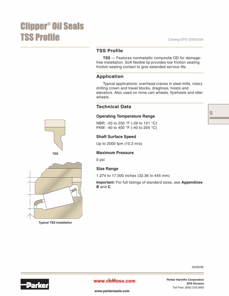
TSS ProfileTSS — Features nonmetallic composite OD for damage-
free installation. Soft flexible lip provides low friction sealingfriction sealing contact to give extended service life.
ApplicationTypical applications: overhead cranes in steel mills, rotary
drilling crown and travel blocks, draglines, hoists andelevators. Also used on mine cart wheels, flywheels and idlerwheels.
Technical Data
Operating Temperature Range
NBR: -20 to 250 °F (-29 to 121 °C)FKM: -40 to 400 °F (-40 to 204 °C)
Shaft Surface Speed
Up to 2000 fpm (10.2 m/s)
Maximum Pressure
0 psi
Size Range
1.274 to 17.500 inches (32.36 to 445 mm)
Important: For full listings of standard sizes, see AppendicesB and C.
03/28/06
BleedsPg72to122.indd 19 4/10/2006 1:28:10 PM
www.comoso.com

5
CClliippppeerr®® OOiill SSeeaallssCatalog EPS 5350/USA
5-20 Parker Hannifin CorporationEPS Division
Toll Free: (800) 233-3900www.parkerseals.com
DDLL PPrrooffiillee
DL
DL ProfilesDL — Spring-loaded dual lip seal. Features nonmetallic
composite OD for damage-free installation.
ApplicationDual spring-loaded lips are used when the separation of
two fluids is required. The design is also used for highcontamination applications in keeping out a dirtyenvironment.
Technical Data
Operating Temperature Range
NBR: -20 to 250 °F (-29 to 121 °C)FKM: -40 to 400 °F (-40 to 204 °C)
Common Materials
NBR – H1L5HNBR – H1L20XNBR – H1L30FKM – H5L16
Shaft Surface Speed
Up to 2000 fpm (10.2 m/s)
Maximum Pressure
0 to 7 psi (0 to 0.48 bar), depending on shaft speed
Important: Contact Customer Service for information on sizeavailability.
03/28/06
BleedsPg72to122.indd 20 4/10/2006 1:28:11 PM
www.comoso.com

CClliippppeerr®® OOiill SSeeaallssCatalog EPS 5350/USA
5-21 Parker Hannifin CorporationEPS Division
Toll Free: (800) 233-3900www.parkerseals.com
RRPPDDTT PPrrooffiillee
RPDT
RPDT ProfileSpring-loaded single lip seal. Features tapered heel.
Available in splits only.
ApplicationTypical applications: pillow blocks.
Technical Data
Operating Temperature Range
NBR: -20 to 250 °F (-29 to 121 °C)
Common Materials
NBR – ALLL5
Shaft Surface Speed
Up to 2000 fpm (10.16 m/s)
Maximum Pressure
0 psi
Important: For full listings of standard sizes, see Appendix D.
03/28/06
5
BleedsPg72to122.indd 21 4/10/2006 1:28:11 PM
www.comoso.com

5
CClliippppeerr®® OOiill SSeeaallssCatalog EPS 5350/USA
5-22 Parker Hannifin CorporationEPS Division
Toll Free: (800) 233-3900www.parkerseals.com
PP,, HH PPrrooffiilleess
P
H
P and H ProfilesP — Features nonmetallic composite OD for damage-free
installation. The P wiper scraper lip extends outside the boreface.
H — Features nonmetallic composite OD for damage-freeinstallation. Shallow cavity rod wiper designed for excludingdust and contamination.
ApplicationP Wiper — Used in reciprocating applications.
H Wiper — Used in reciprocating and rotary applications.
Technical Data
Operating Temperature Range
NBR: -20 to 250 °F (-29 to 121 °C)FKM: -40 to 400 °F (-40 to 204 °C)
Shaft Surface Speed
P Wiper — Up to 300 fpm reciprocating (1.5 m/s)
H Wiper — Up to 300 fpm reciprocating (1.5 m/s), 2000 fpmrotary (10.2 m/s)
Maximum Pressure
0 psi
Size Range
P Wiper — 3/8 to 30 inches (9.5 to 762 mm)H Wiper — 3/8 to 30 inches (9.5 to 762 mm)
Important: For full listings of standard sizes, see AppendicesB and C.
03/28/06
Note: Reciprocating application may require bore plate.
BleedsPg72to122.indd 22 4/10/2006 1:28:11 PM
www.comoso.com

5
CClliippppeerr®® OOiill SSeeaallssCatalog EPS 5350/USA
5-23 Parker Hannifin CorporationEPS Division
Toll Free: (800) 233-3900www.parkerseals.com
SSSS,, SSDDSS PPrrooffiilleess
SS
SDS
SS and SDS ProfilesSS — General purpose springless single lip seal.
Features nonmetallic composite OD for damage-freeinstallation.
SDS — General purpose springless dual lip. Featuresnonmetallic composite OD for damage-free installation.
ApplicationFor grease retention and exclusion of light dust and fluids.
Typical light duty applications.
Technical Data
Operating Temperature Range
NBR: -20 to 250 °F (-29 to 121 °C)FKM: -40 to 400 °F (-40 to 204 °C)
Common Materials
Shaft Surface Speed
Up to 2000 fpm (10.2 m/s)
Maximum Pressure
0 to 7 psi (0 to 0.48 bar), depending on shaft speed
Size Range
SS — 1/4 to 6 inches (6.4 to 152 mm)SDS — 1/2 to 12.835 inches (12.7 to 326 mm)
Important: For full listings of standard sizes, see AppendicesB and C.
03/28/06
Common Materials
NBR – H1L5HNBR – H1L20XNBR – H1L30FKM – H5L16
BleedsPg72to122.indd 23 4/10/2006 1:28:12 PM
www.comoso.com

5
CClliippppeerr®® OOiill SSeeaallssCatalog EPS 5350/USA
5-24 Parker Hannifin CorporationEPS Division
Toll Free: (800) 233-3900www.parkerseals.com
CClliippppeerr SSlliippttiittee PPrrooffiillee
Clipper Sliptite
Clipper Sliptite ProfilesClipper Sliptite — The Clipper Sliptite utilizes a layer of
PTFE bonded to the sealing lip to reduce excessive wearingon the shaft and seal. Features nonmetallic composite OD.
ApplicationWith the PTFE lip, the seal can be utilized in dry running
applications, at higher speeds, and exhibits a broaderrange of chemical compatibility: electric motors, gearboxes,pumps, fans and custom equipment.
Technical Data
Operating Temperature Range
NBR: -20 to 250 °F (-29 to 121 °C)FKM: -40 to 400 °F (-40 to 204 °C)
Common Materials
NBR – H1L5HNBR – H1L20XNBR – H1L30FKM – H5L16
Shaft Surface Speed
Up to 5000 fpm (25.4 m/s)
Maximum Pressure
0 to 7 psi (0 to 0.48 bar), depending on shaft speed
Important: For full listings of standard sizes, see AppendicesB and C.
03/28/06
BleedsPg72to122.indd 24 4/10/2006 1:28:12 PM
www.comoso.com

5
CClliippppeerr®® OOiill SSeeaallssCatalog EPS 5350/USA
5-25 Parker Hannifin CorporationEPS Division
Toll Free: (800) 233-3900www.parkerseals.com
TTMMAALL,, TTMMAASS PPrrooffiilleess
TMAL
TMAS
TMAL and TMAS ProfilesTMAL — Features a stainless steel outer case containing
a machined PTFE spring-loaded sealing element.
TMAS — Features a stainless steel outer case containinga machined PTFE non-spring-loaded sealing element.
ApplicationTMAL and TMAS seals are designed for corrosive
chemical service and FDA application.
Technical Data
Operating Temperature Range
PTFE: -40 to 500 °F (-40 to 260 °C)
Common Materials
Outer Case — Stainless SteelSealing Element — PTFE
Shaft Surface Speed
Up to 2500 fpm (12.7 m/s)
Maximum Pressure
0 to 7 psi (0 to 0.48 bar), depending on shaft speed
Important: For full listings of standard sizes, see AppendicesB and C.
03/28/06
BleedsPg72to122.indd 25 4/10/2006 1:28:12 PM
www.comoso.com

5
CClliippppeerr®® OOiill SSeeaallssCatalog EPS 5350/USA
5-26 Parker Hannifin CorporationEPS Division
Toll Free: (800) 233-3900www.parkerseals.com
MMIISSTT PPrrooffiillee,, LLiiffeeLLiinnee
MIST
MIST ST with Button
LifeLine
The above profiles available with spacerbuttons for grease purging in applicationsrequiring back-to-back sealing.
MIST, MIST ST and LifeLine ProfilesMIST — Heavy duty spring-loaded single lip. Features
nonmetallic composite OD for damage-free installation. MISTfeatures molded-in spring to eliminate spring dumping.
STMIST— Heavy duty spring-loaded single lip. Featurescomposite OD metal band reinforced construction forabsorbing shock load and greater bore retention. STMISTfeatures molded-in spring to eliminate spring dumping.
LifeLine — Spring-loaded single lip features heavy dutyrubber covered metal insert. LifeLine features metal insert for absorbing shock load and greater bore retention.LifeLine features molded-in spring to eliminate spring dumping.
ApplicationFor heavy duty applications, work rolls, paper mills,
backup rolls and custom equipment.
Technical Data
Operating Temperature Range
NBR: -20 to 250 °F (-29 to 121 °C)
Common Materials
NBR – H1L5HNBR – H1L20XNBR – H1L30FKM – H5L16
Shaft Surface Speed
Up to 3200 fpm (16.3 m/s)
Maximum Pressure
0 to 7 psi (0 to 0.48 bar), depending on shaft speed
Size Range
Available shaft diameter range is 5 to 65 inches (127 to1651 mm).
Important: For full listings of standard sizes, see AppendicesB and C.
03/28/06
BleedsPg72to122.indd 26 4/10/2006 1:28:13 PM
www.comoso.com

5
CClliippppeerr®® OOiill SSeeaallssCatalog EPS 5350/USA
5-27 Parker Hannifin CorporationEPS Division
Toll Free: (800) 233-3900www.parkerseals.com
RRUUPP,, RRPPDD PPrrooffiilleess
RUP
RPD
RUP/RPD and RPD ProfilesRUP/RPD — General purpose spring-loaded, single lip
Features nonmetallic OD for damage-free installation.Available in solid or split.
Splits — Feature a positive bore retention and require nocover plate.
ApplicationTypical applications: motors, gearboxes, pumps, fans,
industrial rolls and custom equipment. Split seals aredesigned for applications where equipment is unable to bedisassembled due to time constraints.
Technical DataOperating Temperature RangeNBR: -20 to 250 °F (-29 to 121 °C)FKM: -40 to 400 °F (-40 to 204 °C)
Common MaterialsNBR – H1L5HNBR – H1L30XNBR – H1L20FKM – H5L16
Shaft Surface SpeedUp to 2000 fpm (10.2 m/s)
Maximum Pressure0 to 3 psi (0 to 0.20 bar), designed for vented applications(solid design), 0 psi on split designs
Size RangeSplit seal available shaft diameter range is 0.500 to
65 inches (13 to 1651 mm).
Part NumberingWhen ordering, use the shaft diameter of the split seal as
the prefix to the mold number.
4673 H1L5 is the part number for a solid 4673 seal in NBR.
1100 4673 is the part number for a 4673 seal split downfor 11" shaft in NBR.
1100 4673 V is the part number for a 4673 seal split downfor 11" shaft in FKM.
Important: For full listings of standard sizes, see AppendicesB, C and D.
03/28/06
BleedsPg72to122.indd 27 4/10/2006 1:28:13 PM
www.comoso.com

5
CClliippppeerr®® OOiill SSeeaallssCatalog EPS 5350/USA
5-28 Parker Hannifin CorporationEPS Division
Toll Free: (800) 233-3900www.parkerseals.com
SSpplliitt CClliippppeerr OOiill SSeeaallssDescription
Split Clipper Oil Seals have the same superiorcharacteristics as solid, Clipper Oil Seals, but arefactory-split at one place in the circumference.This permits installation over the side of a shaft,rather than over the end, and often can savedismantling the equipment in order to replacethe existing seals.
Solid Clipper Oil Seals should be usedwhenever practical to provide maximum bearingprotection in rotating shaft applications. However,installing a solid seal in a failed application can becostly and time consuming. In such cases, SplitClipper Oil Seals can be used to minimizeunscheduled downtime, specifically whereequipment cannot be uncoupled. These seals willprovide long and efficient service until major orscheduled machine overhaul permits convenientinstallation of a regular non-split seal.
Split Clipper Oil Seals are available in Series R, RPD and RUP profiles, depending upon shaftdiameter (see Page 5-27). They are widely used as replacement seals because they providesuperior bearing protection and embody a uniqueprinciple of design. The tough, dense outer caseand a soft, flexible lip are concentrically moldedas a single unit. The seal’s nonmetallic outer caseforms a leak-free, press fit in the housing, conforming to minor surface irregularities.
Split Clipper seals provide excellent retentionof grease and light oil splash. Some weepage in oilsplash applications may occur.
Advantages• Saves costly downtime. Speed repairs.
• Easy installation with no special tools required.
• No backup plates required.
• Corrosion-resistant. Reduce bore surfaceseizing.
• Stainless steel coil garter spring helps keepsplit junction tight and compensates for minorshaft irregularities.
• Flat lip contact design compensates for minorsplit-end misalignment.
03/28/06
BleedsPg72to122.indd 28 4/10/2006 1:28:14 PM
www.comoso.com

5
Clipper® slaeSliOreppilCtilpSslaeSliOCatalog EPS 5350/USA
5-29 Parker Hannifin CorporationEPS Division
Toll Free: (800) 233-3900www.parkerseals.com
Important NotesFor Split Clipper Oil Seals to work with
reasonable efficiency, the seals must be split atthe factory. A precisely calculated wedge-shapedsegment must be removed from a pre-molded,oversized seal to assure proper bore cavity andshaft fit. It is not a simple knife-cut. DO NOTATTEMPT TO ALTER THE RECEIVED SIZEON THE JOB SITE.
Split Clipper Oil Seals are made for use inhorizontal shaft applications for grease and oil.The seals are not recommended for bottominstallation on vertical shafts where oil is used.The seals can be used for top installation onvertical shafts.
Parker does not recommended Split ClipperOil Seals for use in pressure service, as theunsupported split junction area will separate,causing leakage.
Split Clipper Oil Seals are not recommendedfor abnormal shaft runouts or misalignments.
Converting to Split Clipper Oil Seals
To convert existing equipment from solid oilseals to Split Clipper Oil Seals, the followingprocedure should be followed:
1. Establish the nominal shaft diameter borediameter and housing depth of existing seal orequipment. The original equipment drawings aremost helpful. Note that no backup plate is requiredwith Split Clipper Oil Seals.
2. Refer to engineering and design data andthe size listings. Determine equipment operatingconditions for shaft speed, runout, temperature,etc., to verify they are within recommendedapplication limits.
Manufacturers of equipment who wish toprovide field service interchangeability with solidoil seal, should consider the following:
1. Design equipment to provide adequate axialspacing, a minimum 2" (5.08 cm), between theoutside bore cavity face and adjacent equipmentcomponents. This is needed to provide room forremoval of the old seal and installation of the newseal.
2. Select a nonmetallic Clipper Seal fororiginal installation having the same shaft, boreand width sizes as the appropriate Split Oil Seallisted. A Clipper Oil Seal should be used for original installation because removal of a conventionalmetallic-cased oil seal and splitting it to get it offthe shaft, would be extremely difficult in theconfined space usually encountered.
3. Split Clipper Oil Seals are sized for a press-fit engagement when installed in the bore. It ismost important that all equipment dimensions,tolerances, entrance chamfer and mating metalfinishes be maintained within limitations specified.
03/28/06
Retrofitting Existing Equipment
New Equipment Design
BleedsPg72to122.indd 29 4/10/2006 1:28:14 PM
www.comoso.com

5
reppilCslaeSliOreppilCtilpS ® Oil Seals
5-30 Parker Hannifin CorporationEPS Division
Toll Free: (800) 233-3900www.parkerseals.com
Catalog EPS 5350/USA
How to Calculate Solid to Split Oil Seals
Important: For full listings of standard sizes andsplitable solid seals, see Appendix D.
(OD - ID = Column C)
Example: 2.813 - 2.000 = 0.813
OD ID Column C
Table 5-8. Split Seal Guide
Column A Column B Column C Column DShaft
Diameter MoldNo.
Add toShaft Dia.
for Seal ODSeal
WidthMin. Max.1.875 – 2.000 3625 1.000 0.4381.875 – 2.000 7081 0.813 0.375
1.875 – 2.000 7131 0.750 0.375
1.875 – 2.000 18759 1.000 0.500
2.000 – 2.125 3930 1.250 0.500
2.000 – 2.125 4868 1.000 0.375
2.000 – 2.125 6207 1.184 0.500
2.000 – 2.125 19359 1.375 0.500
03/28/06
As an example, assume the current equip-ment has the following dimensions:
Shaft Diameter = 2.000”Housing Diameter = 2.813”Housing Width = .375”
To see if a split seal size is available, first check the listing in Appendix B. Find the dimen-sion matching the size requirement which has “SPLIT” listed as seal type. For the dimensions above, Part number 0200 7081 is the correct size and can be found in Appendix B.
If the split seal size is not listed in Appendix Bthe method below can be used for less popular sizes.
Using Conversion Chart In Appendix D
The solid to split seal calculation chart (Appendix D) consists of the following columns. See Table 5-8for example.
Column A = Shaft Diameter Range ( Min & Max)Column B = Mold NumberColumn C = Dimension added to shaft diameter, (Column A) to determine Split OD dimensionColumn D = Width of the seal
Step 1. To determine if shaft size is available find a matching shaft diameter range in column A. In this example all sizes in Table 5.8 can be spilt for a 2.000” shaft.
Step 2. Subtract the housing O.D. by the shaft diameter. If result is listed in Column C, a seal with the correct O.D. can be supplied. In the example this dimension is .813”.
Step 3. Locate a Mold number in column B that matches BOTH the shaft diameter range and and the Column C number from the formula. In this example Mold Number 7081 matches both columns and can be split to the required size.
Step 4. Use dimension in Column D for available seal width.
To order the 7081 split for a 2” shaft, a prefix is added to the solid seal mold number to form the part number. See example below:
Split Part No. Dimensions0200 7081 2.000” x 2.813” x .375”
Additional examples:Split Part No. Dimensions0618 4548 6.188” x 7.437” x .615”1087 3553 10.875” x 12.875” x .812”M 0130 3788 130 mm x 150 mm x 9.5 mm
Contact customer service for assistance if needed.
BleedsPg72to122.indd 30 4/10/2006 1:28:15 PM
www.comoso.com