ccn 1 ppt
DESCRIPTION
CCN 1 pptTRANSCRIPT
CCN-10EC71 Computer Communication Networks
TEXT BOOK:Data Communication and Networking, B Forouzan, 4th Ed, TMH2006

PART – A UNIT - 1 Layered tasks, OSI Model, Layers in OSI model, TCP?IP Suite, Addressing, Telephone and cable networks for data transmission, Telephone networks, Dial up modem, DSL, Cable TV for data transmission. 7 Hours
UNIT - 2 DATA LINK CONTROL: Framing, Flow and error control, Protocols, Noiseless channels and noisy channels, HDLC. 6 Hours
UNIT - 3 MULTIPLE ACCESSES: Random access, Controlled access, Channelisation. 6 Hours
UNIT - 4 Wired LAN, Ethernet, IEEE standards, Standard Ethernet. Changes in the standards, Fast Ethernet, Gigabit Ethernet, Wireless LAN IEEE 802.11 7 Hours
PART – B UNIT - 5 Connecting LANs, Backbone and Virtual LANs, Connecting devices, Back bone Networks, Virtual LANs 7 Hours
UNIT - 6 Network Layer, Logical addressing, Ipv4 addresses, Ipv6 addresses, Ipv4 and Ipv6 Transition from Ipv4 to Ipv6. 6 Hours
UNIT - 7 Delivery, Forwarding, Unicast Routing Protocols, Multicast Routing protocols. 6 Hours
UNIT - 8 Transport layer Process to process Delivery, UDP, TCP, Domain name system, Resolution. 7 Hours

Basic Concepts
When we communicate, we are sharing information.
This sharing can be local or remote.
The term telecommunication, which includes telephony, telegraphy, and television, means communication at a distance.
Data Communication: The exchange of data between two devices via some form of transmission medium such as a wire cable.

For data communications to occur, the communicating devices must be part of a communication system
Combination of hardware (physical equipment) and software (programs).
Delivery, accuracy, timeliness, and jitter.
Delivery. The system must deliver data to the correct destination.
Accuracy. The system must deliver the data accurately. Data that have been altered in transmission and left uncorrected are unusable.
Timeliness. The system must deliver data in a timely manner. Data delivered late are useless.
Real-time transmission- tele conference , video conference
Jitter. Jitter refers to the variation in the packet arrival time.
It is the uneven delay in the delivery of audio or video packets.

5 Components of Data Communication

Message: The message is the information (data) to be communicated. Popular forms of information include text, numbers, pictures, audio, and video.
Sender: The sender is the device that sends the data message. It can be a computer, workstation, telephone handset, video camera.
Receiver. The receiver is the device that receives the message.
Transmission medium: It is the physical path by which a message travels from sender to receiver. Wire, fiber-optic cable, and radio waves.
Protocol: It is a set of rules that control data communications. It represents an agreement between the communicating devices. Without a protocol, two devices may be connected but not communicating
Bluetooth protocol
Fibre Channel network protocols
Internet Protocol Suite
OSI protocols
Routing protocols
FTP File Transfer Protocol
SMTP Simple Mail Transfer Protocol
TCP Transmission Control Protocol

Data Flow
Communication between two devices can be simplex, half-duplex, or full-duplex.

Types of connection
Point-to-point
A point-to-point connection provides a dedicated link between two devices.
Most point-to-point connections use an actual length of wire or cable to connect the two ends, but other options, such as microwave or satellite links, are also possible.
Point-to-point connection between the remote control and the television's control system.

Multipoint A multipoint connection is one in which more than two specific devices share a single link.
In a multipoint environment, the capacity of the channel is shared, either spatially
or temporally.
If several devices can use the link simultaneously, it is a spatially shared connection.
If users must take turns, it is a timeshared connection.
Categories of network
LAN: Usually privately owned and links the devices in a single office, building, or campus. LAN size is limited to a few kilometers.
WAN:A wide area network (WAN) provides long-distance transmission of data, image, audio, and video information over large geographic areas that may comprise a country, a continent, or even the whole world
MAN:A metropolitan area network (MAN) is a network with a size between a LAN and a WAN. It normally covers the area inside a town or a city

UNIT 1
Layered tasks,OSI ModelLayers in OSI modelTCP/IP protocol Addressing,Telephone and cable networks for data transmission Telephone networksDial up modem,DSL Cable TV for data transmission. 7 Hrs

A network is a combination of hardware and software that sends data from one location to another.
The hardware consists of the physical equipment that carries signals from one point of the network to another.
The software consists of instruction sets that make possible the services that we expect from a network.

Layered Tasks

At the Sender Site:
Higher layer. The sender writes the letter, inserts the letter in an envelope, writes the sender and receiver addresses, and drops the letter in a mailbox.
Middle layer. The letter is picked up by a letter carrier and delivered to the post office.
Lower layer. The letter is sorted at the post office; a carrier transports the letter.
On the Way On the way to the recipient's local post office, the letter may actually go through a
central office. It may be transported by truck, train, airplane, boat, or a combination of these.
At the Receiver Site o Lower layer. The carrier transports the letter to the post office.
o Middle layer. The letter is sorted and delivered to the recipient's mailbox.
o Higher layer. The receiver picks up the letter, opens the envelope, and reads it.

There are three different activities at the sender site and another three activities at the receiver site.
The task of transporting the letter between the sender and the receiver is done by the “carrier”
Each layer at the sending site uses the services of the layer immediately below it.
The sender at the higher layer uses the services of the middle layer.
The middle layer uses the services of the lower layer.
The lower layer uses the services of the carrier.
Conclusion

17
THE OSI MODEL
• Open Systems Interconnection model.
• It is a 7 layers model
• It was first introduced in the late 1970s
• OSI developed by International Standards Organization (ISO).
• It is a multinational body dedicated to worldwide agreement on
international standards.

18
The purpose of the OSI model:
• To show how to establish communication between different systems without
changing to the logic of the underlying hardware and software.
• The OSI model is not a protocol; it is a model for understanding and
designing a network architecture that is flexible and robust.
ISO is the organization. OSI is the model.

19
Layered Architecture
Fig: 2.1 Seven layers of the OSI model

Categories of network

As the message travels from A to B, it may pass through many intermediate nodes.
These intermediate nodes usually involve only the first three layers of the OSI model.
Each layer defines a family of functions distinct from those of the other layers.
Within a single machine, each layer calls upon the services of the layer just below.
Ex: Layer 3 uses the services provided by layer 2 and provides services for layer 4.

Peer-to-peer process
Between machines, layer x on one machine communicates with layer x on another machine.
This communication is governed by series of rules
called protocols.
The processes on each machine that communicate at a given layer are called peer-to-peer processes.

Device A sends a stream of bits to device B (through intermediate nodes).
Each layer in the sending device adds its own information to the message it receives from the layer just above it and passes the whole package to the layer just below it.
At layer 1 the entire package is converted to a form that can be transmitted to the
receiving device.
At the receiving machine, the message is unwrapped layer by layer, with removing the data meant for it.
Ex: layer 2 removes the data meant for it, then passes the rest to layer 3. Layer 3 then removes the data meant for it and passes the rest to layer 4, and so on.

Interfaces between layers
The passing of the data and network information 7-1 and 1-7 is made possible by an interface between each pair of adjacent layers.
Each interface defines the information and services a layer must provide for the layer above it.
Well-defined interfaces and layer functions provide modularity to a network.
Modularity is the degree to which a system's components may be separated and recombined

Organization of the layers
3 sub groups
1,2 and 3 : network support layers
5,6 and 7: user support layers
4

1,2,3: deal with physical aspects of moving data- physical connections, physical addressing, transport timing.
Combination of hardware and software, except physical layer, which is mostly hardware.
5,6,7: they allow interoperability among software systems.
Interoperability is the ability of a system or a product to work with other systems or products without special effort.
Software
4: links the two subgroups and ensures that what the lower layers have transmitted is in a form that the upper layers can use and vice versa.

D7 means the data unit at layer 7, D6 means the data unit at layer 6, and so on.
The process starts at layer 7 (the application layer), then moves from layer to layer in descending, sequential
order.
At each layer, a header, or possibly a trailer, can be added to the data unit.
Headers are information structures which identifies the information that follows.
Trailers contain error-checking data which is useful for confirming the accuracy and status of the transmission.

Commonly, the trailer is added only at layer 2.
When the formatted data unit passes through the physical layer (layer 1), it is changed into an electromagnetic signal and transported along a physical link.
Upon reaching its destination, the signal passes into layer 1 and is transformed back into digital form.
The data units then move back up through the OSI layers.
As each block of data reaches the next higher layer, the headers and trailers attached to it at the corresponding sending layer are removed.
By the time it reaches layer 7, the message is again in a form appropriate to the application and is made available to the recipient.

Encapsulation
A packet (header and data) at level 7 is encapsulated in a packet at level 6.
The whole packet at level 6 is encapsulated in a packet at level 5, and so on.
In other words, the data portion of a packet at level N - 1 carries the whole packet (data and header and maybe trailer) from level N.
The concept is called encapsulation;
level N - 1 is not aware of which part of the encapsulated packet is data and which part is the header or trailer.
For level N - 1, the whole packet coming from level N is treated as one integral unit.
Encapsulation is the packing of data and functions into a single component.

1. Physical layer
The physical layer coordinates the functions required to carry a bit stream over a physical medium.
It deals with the mechanical and electrical specifications of the transmission medium.
It also defines the procedures and functions that physical devices and interfaces have to perform for transmission to occur.
The physical layer is responsible for movements of individual bits from one hop (node) to the next.

Physical layer is also concerned with the following
1. Physical characteristics of interfaces and medium between the devices and the transmission medium.
It also defines the type of transmission medium.
2. Representation of bits.
The physical layer data consists of a stream of bits.
To be transmitted, bits must be encoded into signals(electrical or optical)
The physical layer defines the type of encoding.


3. Data rate
The transmission rate-the number of bits sent each second-is also defined by the physical layer.
4. Synchronization of bits.
The sender and receiver not only must use the same bit rate but also must be synchronized at the bit level.
5. Line configuration.
The physical layer is concerned with the connection of devices to the media.
point-to-point configuration or multipoint configuration.
6. Physical topology.
The physical topology defines how devices are connected to make a network.
Devices can be connected by using a mesh topology (every device is connected to every other device)
star topology (devices are connected through a central device)
ring topology (each device is connected to the next, forming a ring)
bus topology (every device is on a common link)
a hybrid topology (this is a combination of two or more topologies).

7. Transmission mode.
The physical layer also defines the direction of transmission between two devices: simplex, half-duplex, or full-duplex.
In simplex mode, only one device can send; the other can only receive. The simplex mode is a one-way
communication.
In the half-duplex mode, two devices can send and receive, but not at the same time.
In a full-duplex (or simply duplex) mode, two devices can send and receive at the same time.

Data Link Layer
The data link layer is responsible for moving frames from one hop (node) to the next.
1. Framing. The data link layer divides the stream of bits received from the
network layer into manageable data units called frames.
2. Physical addressing. If frames are to be distributed to different systems on the network, the
data link layer adds a header to the frame to define the sender and/or receiver of the frame.
3. Flow control. If the rate at which the data are absorbed by the receiver is less than
the rate at which data are produced in the sender, the data link layer imposes a flow control mechanism to avoid overloading the receiver.


4. Error control.
The data link layer adds reliability to the physical layer by adding mechanisms to detect and retransmit damaged or lost frames.
It also uses a mechanism to recognize duplicate frames. Error control is normally achieved through a trailer added to the end of the frame.
5. Access control.
When two or more devices are connected to the same link, data link layer protocols are necessary to determine which device has control over the link at any given time.

Hop to Hop Delivery of frames- nodes

Network Layer
The network layer is responsible for the source-to-destination delivery of a packet.
The network layer is responsible for the delivery of individual packets from the source to the destination
1. Logical addressing: The network layer adds a header to the packet coming from the upper layer that includes the logical addresses of the sender and receiver.

2. Routing. When independent networks are connected to create internetworks or a large network, the connecting devices (called routers or switches) route or switch the packets to their final destination.
As the figure shows source-to-destination delivery.
The network layer at A sends the packet to the network layer at B.
When the packet arrives at router B, the router makes a decision based on the final destination (F) of the packet.
Router B finds the next hop i.e. router E.
The network layer at B, therefore, sends the packet to the network layer at E.
The network layer at E, in turn, sends the packet to the network layer at F.

Transport Layer
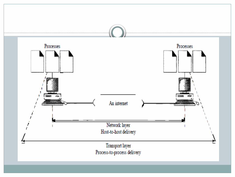
The transport layer is responsible for process-to-process delivery of the entire message.
Whereas the network layer manages source-to-destination delivery of individual packets.
A process is an application program running on a host.
The transport layer is responsible for the delivery of a message from one process to another.

1. Service-point addressing:
Computers often run several programs at the same time.
For this reason, source-to-destination delivery means delivery not only from one computer to the next but also from a specific process (running program) on one computer to a specific process (running program) on the other.
The transport layer header include a type of address called a service-point address.
The network layer gets each packet to the correct computer; the transport layer gets the entire message to the correct process on that computer.

2. Segmentation and reassembly:
A message is divided into transmittable segments(messages) , with each segment containing a sequence number.
These numbers enable the transport layer to reassemble the message correctly upon arriving at the destination .
It helps in to identifying and replace packets that were lost in transmission.
3. Flow control:
Like the data link layer, the transport layer is responsible for flow control. However, flow control at this layer is performed end to end rather than across a single link.
4. Error control: Like the data link layer, the transport layer is responsible for error
control. However, error control at this layer is performed process-to-process rather than across a single link.
The sending transport layer makes sure that the entire message arrives at the receiving transport layer without error.
Error correction is usually achieved through retransmission.

Session layer
The session layer is responsible for dialog control and synchronization.
1. Dialog control: The session layer allows two systems to enter into a dialog.
It allows the communication between two processes to take place in either simplex, half duplex or full-duplex mode.
1. Simplex dialogs : one way transfers,.example: computer to printer ( computer will send data to printer and printer will receive the data ). 2. Half-Duplex Dialogs - Two-way transfers, Each device must take their turn. Both cannot transfer at the same time. Example:walkies-talkie 3. Full-Duplex Dialogs - Two-way simultaneous data transfers. Each device has it's own channel. for example: telephone.

2. Synchronization. The session layer allows a process to add checkpoints, or synchronization points, to a stream of data.
For example, if a system is sending a file of 2000 pages, it is advisable to insert checkpoints after every 100 pages to ensure that each 100-page unit is received and acknowledged independently.
Presentation layer
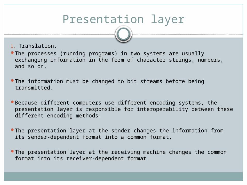
1. Translation. The processes (running programs) in two systems are usually exchanging
information in the form of character strings, numbers, and so on.
The information must be changed to bit streams before being transmitted.
Because different computers use different encoding systems, the presentation layer is responsible for interoperability between these different encoding methods.
The presentation layer at the sender changes the information from its sender-dependent format into a common format.
The presentation layer at the receiving machine changes the common format into its receiver-dependent format.

2. Encryption:
To carry sensitive information, a system must be able to ensure privacy.
Encryption means that the sender transforms the original information to another form and sends the resulting message out over the network.
Decryption reverses the original process to transform the message back to its original form.
3. Compression:
Data compression reduces the number of bits contained in the information.
Data compression becomes particularly important in the transmission of multimedia such as text, audio, and video.
Application layer
The application layer enables the user, whether human or software, to access the network.
It provides user interfaces and support for services such as electronic mail, file access and transfer, shared database management and so on.

Figure shows the relationship of the application layer to the user and the presentation layer.
Of the many application services available, the figure shows only three:
X.4OO (message-handling services), X.500 (directory services), and file transfer, access, and management (FTAM). The user in this example employs X.4OO to send an e-mail message.

Services provided by Application layer
1. File transfer, access, and management:This application allows a user to exchange the files,
creation, modification and deletion of files.
2. Mail services:This application provides the basis for e-mail forwarding
and storage.
3. Directory services:This application provides access for global information
about various objects and services.
55
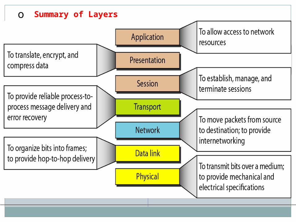
o Summary of Layers

TCP/IP Protocol (Transmission Control Protocol/ Internet Protocol
The layers in the TCP/IP protocol suite do not exactly match those in the OSI model.
The original TCP/IP protocol suite was defined as having four layers: host-to-network, internet, transport, and application.
host-to-network layer is equivalent to the combination of the physical and data link layers.

The internet layer is equivalent to the network layer.
Transport layer in TCP/IP taking care of part of the duties of the session layer.
Application layer is roughly doing the job of the session, presentation, and application layers.


Physical and Data Link Layers
TCP/IP does not define any specific protocol.
It supports all the standard and proprietary protocols.
A network in a TCP/IP internetwork can be a local-area network or a wide-area network.

Network Layer
At the network layer TCP/IP supports the Internetworking Protocol.
IP, in turn, uses four supporting protocols: ARP, RARP, ICMP, and IGMP.
The Internetworking Protocol (IP) is the transmission mechanism used by the TCP/IP protocols.
It is unreliable as IP provides no error checking or tracking.
IP transports data in packets called datagrams, each of which is transported separately.
Datagrams can travel along different routes and can arrive out of sequence or be duplicated.
IP does not keep track of the routes and has no facility for reordering datagrams once they arrive at their destination.

Address Resolution Protocol
The Address Resolution Protocol (ARP) is used to associate a logical address with a physical address.
ARP is used to find the physical address of the node when its logical address(IP address) is known.
On a physical network, such as a LAN, each device on a link is identified by a physical address, usually imprinted on the network interface card (NIC).
A NIC is computer circuit board that is installed in a computer so that it can be connected to a network.

Reverse Address Resolution Protocol
The Reverse Address Resolution Protocol (RARP) allows a host to discover its Internet address when it knows only its physical address.
It is used when a computer is connected to a network for the first time.

Internet Control Message Protocol
The Internet Control Message Protocol (ICMP) is a mechanism used by hosts and gateways to send notification of datagram problems back to the sender.
ICMP sends query and error reporting messages.

Internet Group Message Protocol
The Internet Group Message Protocol (IGMP) is used to facilitate the simultaneous transmission of a message to a group of recipients.

Transport Layer
TCP and UDP.
IP is a host-to-host protocol, meaning that it can deliver a packet from one physical device to another.
UDP and TCP are transport level protocols responsible for delivery of a message from a process (running program) to another process.
A new transport layer protocol, SCTP, has been developed to meet the needs of some newer applications.

Transmission control protocol
It is a process-to-process protocol that adds only port addresses, checksum error control, and length information to the data from the upper layer.
The Transmission Control Protocol (TCP) provides full transport-layer services to applications.
At the sending end of each transmission, TCP divides a stream of data into smaller units called segments.
Each segment includes a sequence number for reordering after receipt, together with an acknowledgment number for the segments received.
User Datagram Protocol
Stream Control Transmission Protocol
The Stream Control Transmission Protocol (SCTP) provides support for newer applications such as voice over the Internet.
It is a transport layer protocol that combines the best features of UDP and TCP.

Application Layer
The application layer in TCP/IP is equivalent to the combined session, presentation, and application layers in the OSI model.
SMTPFTPHTTPDNSSNMPTELNET

Addressing


Physical address
The physical addresses have authority over the network (LAN or WAN).
The size and format of these addresses vary depending on the network.
For example, a 6-byte (48-bit) physical address that is imprinted on the network interface card (NIC)

Most local-area networks use a 48-bit (6-byte) physical address.
Written as 12 hexadecimal digits, every byte (2 hexadecimal digits) is separated by a colons
07:01:02:01 :2C:4B

Logical address
Logical addresses are necessary for universal communications.
A logical address in the Internet is currently a 32-bit address.
The physical addresses will change from hop to hop, but the logical addresses usually remain the same.

Port address
Today, computers are devices that can run multiple processes at the same time.
The end objective of Internet communication is a process communicating with another process.
For example, computer A can communicate with computer C by using TELNET.
At the same time, computer A communicates with computer B by using the File Transfer Protocol (FTP).
For these processes to receive data simultaneously, we need a method to label the different processes.
In other words, they need addresses. In the TCPIIP architecture, the label assigned to a process is called a port address.
A port address in TCP/IP is 16 bits in length.


The sending computer is running three processes at this time with port addresses a, b, and c.
The receiving computer is running two processes at this time with port addresses j and k.
Process a in the sending computer needs to communicate with process j in the receiving computer.
Although both computers are using the same application, the port addresses are different because one is a client program and the other is a server program.

Specific address
Some applications have user-friendly addresses that are designed for that specific address.
Examples include the e-mail address (for example, [email protected]) and the Universal Resource Locator (URL) (for example, www.mhhe.com).
The first defines the recipient of an e-mail , the second is used to find a document on the World Wide Web
Telephone networks
Telephone networks use circuit switching.
The telephone network had its beginnings in the late 1800s.
Plain old telephone system (POTS), was originally an analog system using analog signals to transmit voice.
With the advent of the computer era, in the 1980s, began to carry data in addition to voice.
During the last decade, The network is now digital as well as analog.

Components of telephone network
It is made of three major components:
local loops, trunks, and switching offices.
The telephone network has several levels of switching offices such as end offices, tandem offices, and regional offices.


Local Loops: A twisted-pair cable that connects the
subscriber telephone to the nearest end office or local central office.
The local loop, when used for voice, has a bandwidth of 4000 Hz (4 kHz).
The first three digits of a local telephone number define the office, and the next four digits define the local loop number.

Trunks: Trunks are transmission media that handle the communication
between offices.
A trunk normally handles hundreds or thousands of connections.
Transmission is usually through optical fibers or satellite links.
Switching Offices To avoid having a permanent physical link between any two
subscribers, the telephone company has switches located in a switching office.
A switch connects several local loops or trunks and allows a connection between different subscribers.

LATAs
Local access and transport areas.
LATA is a term used in USA that refers to a geographical area assigned to one or more telephone companies for providing communication services.
Intra LATA & Inter LATA

Intra LATA Services
1. Intra-LATA Services:
The services offered by the common carriers (telephone companies) inside a LATA are called intra-LATA services.
The carrier that handles these services is called a local exchange carrier (LEC).
Before the Telecommunications Act of 1996 intra-LATA services were granted to one single carrier.
After 1996,more than one carrier could provide services inside a LATA.
The carrier that provided services before 1996 are called the Incumbent Local Exchange Carrier (ILEC).

The new carriers that can provide services are called Competitive Local Exchange Carriers
(CLECs).
Figure below shows a LATA and switching offices.
Inter LATA Services
The services between LATAs called Inter-LATA Services
These services handled by Interexchange Carriers (IXCs).
IXCs sometimes called long-distance companies, provide communication
services between two customers in different LATAs.
Major companies providing inter-LATA services include AT&T,MCI,
WorldCom, Sprint, Verizon etc..
The IXCs are long-distance carriers that provide general data
communications services including telephone service.
A telephone call going through an IXC is normally digitized.

Points Of Presence (POP)
Point of presence (POP) connect several LECs and IXCs.
Each IXC that wants to provide inter LATA services in a LATA must have a POP in that
LATA.
The LECs that provide services inside the LATA must provide connections so that every
subscriber can have access to all POPs.
Figure : Point of presences (POPs)

Signaling
In telephony, signaling is the exchange of information between two points in the network.
When the data and control signals are transmitted within the same channel the signaling is said to be "in-band”.
When control signals channel is separate from the data, they are "out-of-band" signals.
The SS7 telephone system uses an entirely separate network for control signals

As telephone networks evolved functionality of the signaling system increased.
The signaling system was required to perform other tasks such as
1. Providing dial tone, ring tone, and busy tone2. Transferring telephone numbers between offices3. Maintaining and monitoring the call4. Keeping billing information5. Providing other functions such as voice mail

Signaling System Seven -SS7

MTP Level 1 : The physical layer in SS7 called message transport part (MTP) level I uses several physical layer specifications.
MTP Level 2: It provides typical data link layer services such as packetizing, using source and destination address in the packet header, and does error checking.
MTP Level 3: It provides end-to-end connectivity (Network layer) Routers and switches route the signal packets from the source to the destination.
Transport Layer: SCCP The signaling connection control point (SCCP) is used for special services such as 800-call processing.
Upper Layers: TUP, TCAP, and ISUP There are three protocols at the upper layers.
Telephone user port (TUP) is responsible for setting up voice calls. It receives the dialed digits and routes the calls.
Transaction capabilities application port (TCAP) let an application program on a computer invoke a procedure on another computer.
ISDN user port (ISUP) can replace TUP to provide services similar to those of an ISDN network.

DIAL UP MODEMS
The term modem is a composite word that refers to the two functional entities that make up the device:
a signal modulator and a signal demodulator.
A modulator creates an analog signal from binary data.
A demodulator recovers the binary data from the modulated signal.
Modem Standards: V.32 ,V.32bis , V.34bis, V.90, V.92

DIGITAL SUBSCRIBER LINE
Digital subscriber line (DSL) technology is one of the most promising for supporting high-speed digital communication
DSL technology is a set of technologies, each differing in the first letter (ADSL, VDSL, HDSL, and SDSL).
The set is often referred to as xDSL, where x can be replaced by A, V, H, or S.

In telecommunications , transmission from information server toward an end user is referred to as downstream
transmission toward the server from the end user is referred to as upstream.
In DSL, the rates of data transfer upstream and downstream are not the same.
In DSL, downstream data rates are higher since the kind of information that needs to get to the user (including still and video images and sound) requires a higher data rate.
User responses back to the computer on the upstream path can be smaller.


Cable TV networks
Traditional Cable TV network: coaxial cables
Hybrid fiber-coaxial network: fiber-optic + co axial cable
Cable for data transfer
CM(cable modem) and CMTS(cable modem transmission system) are 2 key devices .
CM is installed on the subscriber premises
CMTS is installed inside the distribution hub by the cable company.
Data transmission scheme used is DOCSIS- data over cable system interface specification