ccna exam 640-607 certification guideindex-of.co.uk/cisco/ccna 640-607 certification guide.pdf ·...
TRANSCRIPT

CCNA Exam 640-607Certification Guide
Wendell Odom, CCIE #1624
Cisco Press
201 West 103rd Street
Indianapolis, IN 46290 USA
00 CCNA Exam_FM.fm Page i Thursday, March 7, 2002 11:43 AM

ii
CCNA Exam 640-607 Certification Guide
Wendell OdomCopyright© 2002 Lacidar Unlimited, Inc.
Cisco Press logo is a trademark of Cisco Systems, Inc.
Published by:Cisco Press201 West 103rd StreetIndianapolis, IN 46290 USA
All rights reserved. No part of this book may be reproduced or transmitted in any form or by any means, electronic or mechanical, including photocopying or recording, or by any information storage and retrieval system, without written permission from the publisher, except for the inclusion of brief quotations in a review.
Printed in the United States of America 1 2 3 4 5 6 7 8 9 0
First Printing March 2002
Library of Congress Cataloging-in-Publication Number: 2001098200
ISBN: 1-58720-055-4
Warning and Disclaimer
This book is designed to provide information about CCNA Exam 640-607. Every effort has been made to make this book as complete and accurate as possible, but no warranty or fitness is implied.
The information is provided on an “as is” basis. The authors, Cisco Press, and Cisco Systems, Inc. shall have neither liability nor responsibility to any person or entity with respect to any loss or damages arising from the information contained in this book or from the use of the discs or programs that may accompany it.
The opinions expressed in this book belong to the author and are not necessarily those of Cisco Systems, Inc.
Trademark Acknowledgments
All terms mentioned in this book that are known to be trademarks or service marks have been appropriately capitalized. Cisco Press or Cisco Systems, Inc. cannot attest to the accuracy of this information. Use of a term in this book should not be regarded as affecting the validity of any trademark or service mark.
Feedback Information
At Cisco Press, our goal is to create in-depth technical books of the highest quality and value. Each book is crafted with care and precision, undergoing rigorous development that involves the unique expertise of members of the professional technical community.
00 CCNA Exam_FM.fm Page ii Thursday, March 7, 2002 11:43 AM

iii
Reader feedback is a natural continuation of this process. If you have any comments regarding how we could improve the quality of this book, or otherwise alter it to better suit your needs, you can contact us through e-mail at [email protected]. Please be sure to include the book title and ISBN in your message.
We greatly appreciate your assistance.
Publisher John WaitEditor-In-Chief John KaneCisco Systems Program Manager Michael HackertExecutive Editor Brett BartowManaging Editor Patrick KanouseDevelopment Editor Christopher ClevelandProject Editor Marc FowlerCopy Editors Gayle Johnson
Krista HansingTechnical Editors David Barnes
Tim FaulkSteven KalmanBarb Nolley
Team Coordinator Tammi RossBook Designer Gina RexrodeCover Designer Louisa KlucznikProduction Team Scan Communications Group, Inc.Indexer Tim Wright
Corporate HeadquartersCisco Systems, Inc.170 West Tasman DriveSan Jose, CA 95134-1706USAhttp://www.cisco.comTel: 408 526-4000
800 553-NETS (6387)Fax: 408 526-4100
European HeadquartersCisco Systems Europe11 Rue Camille Desmoulins92782 Issy-les-Moulineaux Cedex 9Francehttp://www-europe.cisco.comTel: 33 1 58 04 60 00Fax: 33 1 58 04 61 00
Americas HeadquartersCisco Systems, Inc.170 West Tasman DriveSan Jose, CA 95134-1706USAhttp://www.cisco.comTel: 408 526-7660Fax: 408 527-0883
Asia Pacific HeadquartersCisco Systems Australia, Pty., LtdLevel 17, 99 Walker StreetNorth SydneyNSW 2059 Australiahttp://www.cisco.comTel: +61 2 8448 7100Fax: +61 2 9957 4350
Copyright © 2000, Cisco Systems, Inc. All rights reserved. Access Registrar, AccessPath, Are You Ready, ATM Director, Browse with Me, CCDA, CCDE, CCDP, CCIE, CCNA,CCNP, CCSI, CD-PAC, CiscoLink, the Cisco NetWorks logo, the Cisco Powered Network logo, Cisco Systems Networking Academy, Fast Step, FireRunner, Follow Me Browsing,FormShare, GigaStack, IGX, Intelligence in the Optical Core, Internet Quotient, IP/VC, iQ Breakthrough, iQ Expertise, iQ FastTrack, iQuick Study, iQ Readiness Scorecard, TheiQ Logo, Kernel Proxy, MGX, Natural Network Viewer, Network Registrar, the Networkers logo, Packet, PIX, Point and Click Internetworking, Policy Builder, RateMUX,ReyMaster, ReyView, ScriptShare, Secure Script, Shop with Me, SlideCast, SMARTnet, SVX, TrafficDirector, TransPath, VlanDirector, Voice LAN, Wavelength Router,Workgroup Director, and Workgroup Stack are trademarks of Cisco Systems, Inc.; Changing the Way We Work, Live, Play, and Learn, Empowering the Internet Generation, areservice marks of Cisco Systems, Inc.; and Aironet, ASIST, BPX, Catalyst, Cisco, the Cisco Certified Internetwork Expert Logo, Cisco IOS, the Cisco IOS logo, Cisco Press, CiscoSystems, Cisco Systems Capital, the Cisco Systems logo, Collision Free, Enterprise/Solver, EtherChannel, EtherSwitch, FastHub, FastLink, FastPAD, IOS, IP/TV, IPX, LightStream,LightSwitch, MICA, NetRanger, Post-Routing, Pre-Routing, Registrar, StrataView Plus, Stratm, SwitchProbe, TeleRouter, are registered trademarks of Cisco Systems, Inc. or itsaffiliates in the U.S. and certain other countries.
All other brands, names, or trademarks mentioned in this document or Web site are the property of their respective owners. The use of the word partner does not imply a partnershiprelationship between Cisco and any other company. (0010R)
Cisco Systems has more than 200 offices in the following countries. Addresses, phone numbers, and fax numbers are listed on the Cisco Web site at www.cisco.com/go/offices
Argentina • Australia • Austria • Belgium • Brazil • Bulgaria • Canada • Chile • China • Colombia • CostaRica • Croatia • Czech Republic • Denmark • Dubai, UAE • Finland • France • Germany • Greece • HongKong • Hungary • India • Indonesia • Ireland Israel • Italy • Japan • Korea • Luxembourg • Malaysia •Mexico • The Netherlands • New Zealand • Norway • Peru • Philippines Poland • Portugal • Puerto Rico •Romania • Russia • Saudi Arabia • Scotland • Singapore • Slovakia • Slovenia • South Africa • Spain Sweden• Switzerland • Taiwan • Thailand • Turkey • Ukraine • United Kingdom • United States • Venezuela • Vietnam• Zimbabwe
00 CCNA Exam_FM.fm Page iii Thursday, March 7, 2002 11:43 AM

iv
About the Author
Wendell Odom, CCIE #1624,
is a senior instructor with Skyline Computer. Currently, he is project leader for Skylabs, a service offering access to lab gear and exercises for Cisco Certification Exam practice (http://www.skylinecomputer.com/skylabs.htm). Wendell has worked in the networking arena for 19 years, working in pre- and post-sales technical consulting, teaching, and course development. He has authored portions of over 12 courses, including topics such as IP routing, MPLS, Cisco WAN switches, SNA protocols, andLAN troubleshooting.
About the Technical Reviewers
David Barnes
manages Cisco’s Advanced Services Team in Richardson, Texas. He is CCIE #6563, CCDP, MCSE+I, Master CNE, and a Certified Technical Trainer. The organization he manages specializes in network consulting for many of Cisco’s largest customers. He designed, implemented, and managed networks for numerous Fortune 500 companies in the 10 years before he joined Cisco Systems, Inc. in 1999.
Tim Faulk
is a professor and curriculum developer in the networks department of American Intercontinental University in Atlanta, GA. He holds a master’s degree in education and a Cisco Certified Network Professional certification. He teaches Cisco technology, TCP/IP-related courses, and security courses. He is presently developing a master’s program in network security.
Steven Kalman
is the principal officer at Esquire Micro Consultants, which performs lecturing, writing, and consulting. He has more than 30 years of experience in data processing, with strengths in network design and implementation. He is an instructor and author for Learning Tree International and has written and reviewed many networking-related titles. He holds CCNA, CCDA, ECNE, CNE, CISSP, and CNI certifications.
Barb Nolley
is the president and principal consultant for BJ Consulting, Inc., a small consulting firm that specializes in networking education. Since starting BJ Consulting, she has developed and taught training courses for Novell’s Master CNE certification, as well as several courses for Cisco Systems’ Engineering Education group and a CCNA track for the University of California-Riverside Extension. Her certifications include CCNA, CNE, and CNI. She lives in and works out of an RV with her husband, Joe.
00 CCNA Exam_FM.fm Page iv Thursday, March 7, 2002 11:43 AM
v
Dedications
To the little boys and girls of our Cisco Press team who missed seeing their daddies for the final month it took to plow through the updates for this edition: I pray a blessing of more time with your daddies the next time we change the book! For my precious Hannah Grace, and for Matthew Christopher Cleveland, I thank you for your sacrifices!
Acknowledgments
I can write a 1000-page book, but I can’t find enough words to describe the credit Chris Cleveland deserves for what is good about this book. Michael Jordan, Wayne Gretsky, Chris Cleveland—a list of the absolutely best at what they do! Chris, thanks for putting up with the hand-drawn figures, for meeting my schedule requirements, and for working hard during the holidays. Your ability to edit my style of writing and revising makes my job a breeze. I still refuse to write a book unless you develop it!
Brett Bartow steered the project as executive editor. In his usual unflappable way, he dealt with all the planning and changes with content issues, business issues, and the flow of information to us from Cisco—without ever getting rattled. In the process of hurry up and wait, and then really hurry up, Brett provided calm. Thanks for that, Brett!
For Tammi Ross, who handles a lot of the administrative tasks, thanks for handling things quickly and correctly. It’s great to ask for something at a moment’s notice, and things happen, no problems!
Behind the scenes at Cisco Press is a vast array of talented people—all of whom are shielded from us authors by the development editor, who was Chris Cleveland again in my case. These are people who take figure changes with scribbled notes and make something meaningful and nice-looking out of them. People who fix my English—I never made an A in an English class in high school or college! People who do the meticulous tasks that make the whole book come together—making sure figures fit on the same page as the text that refers to them, making sure the index is complete and accurate, and the like. I have the easy job in this arrangement. Many thanks to you all for the hard and good work!
The technical editors deserve most of the credit for making the content of this book robust and complete. Even with this third edition of the book, I am constantly amazed at what happens when talented technical editors take the time to really read through the material. Brett lined up the “first team” again, with three editors returning from the last edition—David Barnes, Steve Kalman, and Barb Nolley. Tim Faulk joined us for the first time, bringing his perspective from teaching CCNA classes at a university. All the credit for technical errors in this book lies with me, and all credit for the reduction of technical errors lies with these technical editors. But more importantly, they get credit for their input on improving sections, rewording phrases to clarify information, for finding better ways to describe how the technical pieces fit together, for fixing errors when there was a disconnection between my brain and what I wrote, and yes, even for finding errors in subnetting examples—and so much more. Without you, this book simply wouldn’t be nearly as good or as accurate. Many thanks to you for that.
00 CCNA Exam_FM.fm Page v Thursday, March 7, 2002 11:43 AM

vi
Finally, my boss at Skyline Computer, Mike Zanotto (a.k.a. Mike Z), Managing Director, helped this project by letting me schedule the new CCIE Skylabs remote lab offering to go live the same day I had to have this book’s manuscript completed! Seriously, Z always helped by finding a way to give me the time I needed to work on this book and by making sure the job was fun. Thanks, Mike!
Finally, no acknowledgments section could be complete without acknowledging my wife, Kris, who took on all the duties at home with our 7-month-old child during the last month of getting this edition written. She was a trouper, sacrificing without being asked. Thank you so much, my love! Finally, to Jesus Christ, who gives us strength when things are tough, and peace beyond belief—thank you.
00 CCNA Exam_FM.fm Page vi Thursday, March 7, 2002 11:43 AM

vii
Contents at a Glance
Chapter 1
All About the Cisco Certified Network Associate Certification 3
Chapter 2
Cisco IOS Software Fundamentals 27
Chapter 3
OSI Reference Model and Layered Communication 79
Chapter 4
LANs, Bridges, and Switches 145
Chapter 5
Intermediate LANs: Spanning Tree, VLANs, and Trunking 215
Chapter 6
TCP/IP and IP Routing 267
Chapter 7
Routing and Routing Protocols 407
Chapter 8
Understanding Access List Security 489
Chapter 9
WAN Protocols and Design 533
Chapter 10
Frame Relay Concepts and Configuration 605
Chapter 11
Novell IPX 677
Chapter 12
Scenarios for Final Preparation 759
Chapter 13
Hands-on Lab Exercises 823
Appendix A
Answers to the “Do I Know This Already?” Quizzes and Q&A Sections 851
Appendix B
Decimal to Hexadecimal and Binary Conversion Table 933
Appendix C
Subnetting Practice: 25 Subnetting Questions 943
Appendix D
Hands-on Lab Exercises: Solutions (included in PDF format on the CD forthis book)
Index
991
00 CCNA Exam_FM.fm Page vii Thursday, March 7, 2002 11:43 AM

viii
Table of Contents
Chapter 1
All About the Cisco Certified Network Associate Certification 3
Overview of Cisco Certifications 4Exams Required for Certification 6Other Cisco Certifications 7
What’s on the CCNA Exam 8
Cross-Reference Between Exam Topics andBook Chapters 16
Cross-Reference Between Chapter and Exam Topics 17
Recommended Training Paths for CCNA 17
How to Use This Book to Pass the Exam 19I’ve Taken ICND—Now What? 22I’ve Taken the Cisco Networking Academy Courses—Now What? 22I’m New to Internetworking with Cisco, I Will Not Be Taking the ICND Course, and This Book Is My Only Reference—Now What? 23
I’m New to Internetworking with Cisco, I Will Not Be Taking the ICND Course, and I Bought the Interconnecting Cisco Network Devices Book as Well—Now What? 24
I’ve Learned a Lot About CCNA Topics Through Experience, but I Will Not Be Taking the ICND Course—Now What? 24
Conclusion 24
Chapter 2
Cisco IOS Software Fundamentals 27
How to Best Use This Chapter 27
“Do I Know This Already?” Quiz 28
The Cisco IOS Software Command-Line Interface 32Access to the CLI 32CLI Help Features 35Syslog and debug 37
Configuring Cisco IOS Software 39Example Configuration Process 40Router Memory, Processors, and Interfaces 43Managing Configuration Files 44
00 CCNA Exam_FM.fm Page viii Thursday, March 7, 2002 11:43 AM

ix
Upgrading Cisco IOS Software and the Cisco IOS Software Boot Process 50Upgrading an IOS Image into Flash Memory 50The Cisco IOS Software Boot Sequence 53
Scenario 2-1 70Questions on Scenario 2-1 71
Scenario 2-2 72Questions on Scenario 2-2 72
Scenario 2-1 Answers 75
Scenario 2-2 Answers 76
Chapter 3
OSI Reference Model and Layered Communication 79
How to Best Use This Chapter 79
“Do I Know This Already?” Quiz 80
OSI: Concepts, Layers, and Encapsulation 84OSI Reference Model: Origin and Evolution 84OSI Layers 85Layering Concepts and Benefits 89Interaction Between OSI Layers 90Data Encapsulation 94The TCP/IP and NetWare Protocols 97
OSI Transport Layer Functions 98Connection-Oriented Versus Connectionless Protocols 98Error Recovery 99Flow Control 102
OSI Data Link Layer Functions 105Data Link Function 1: Arbitration 106Data Link Function 2: Addressing 107Data Link Function 3: Error Detection 109Data Link Function 4: Identifying the Encapsulated Data 109Summary: Data Link Functions 113
OSI Network Layer Functions 114Routing 114Network Layer (Layer 3) Addressing 118
Scenario 3-1 136Task 1 for Scenario 3-1 137Task 2 for Scenario 3-1 138Task 3 for Scenario 3-1 138
00 CCNA Exam_FM.fm Page ix Thursday, March 7, 2002 11:43 AM

x
Answers to Task 1 for Scenario 3-1 139
Answers to Task 2 for Scenario 3-1 139
Answers to Task 3 for Scenario 3-1 141
Chapter 4
LANs, Bridges, and Switches 145
How to Best Use This Chapter 145
“Do I Know This Already?” Quiz 146
LAN Overview 15010-Mbps Ethernet 151LAN Addressing 157LAN Framing 158Fast Ethernet and Gigabit Ethernet 161LAN Standards 162Bridging and Switching 164Transparent Bridging 165LAN Switching 170Comparison of LAN Segmentation Using Bridges, Switches,and Routers 175
LAN Switch Configuration 178Basic 1900 Switch Configuration 179
Scenario 4-1: LAN Switch Configuration 203
Scenario 4-2: LAN Switch Concepts 204
Answers to Scenario 4-1: LAN Switch Configuration 206
Answers to Scenario 4-2: LAN Switch Concepts 210
Chapter 5
Intermediate LANs: Spanning Tree, VLANs, and Trunking 215
How to Best Use This Chapter 216
“Do I Know This Already?” Quiz 216
Spanning-Tree Protocol 220What Spanning Tree Does 222How Spanning Tree Works 223Spanning-Tree Protocol Summary 229
Virtual LANs 230VLAN Trunking Protocol (VTP) 237
00 CCNA Exam_FM.fm Page x Thursday, March 7, 2002 11:43 AM

xi
VLAN and Trunking Configuration 240Basic VLAN Configuration 241
Scenario 5-1: LAN Switch Configuration 257
Answers to Scenario 5-1: LAN Switch Configuration 257
Chapter 6
TCP/IP and IP Routing 267
How to Best Use This Chapter 267
“Do I Know This Already?” Quiz 268
TCP/IP Protocols 272Overview of a Sample TCP/IP Network 272Transmission Control Protocol 277User Datagram Protocol 284Address Resolution Protocol 286Internet Control Message Protocol 287FTP and TFTP 294
IP Addressing and Subnetting 296IP Addressing and Subnetting 297Four Steps to Answering IP Addressing Questions 309CIDR, Private Addressing, and NAT 337
IP Configuration 342Using Secondary Addresses 355IP Addressing with Frame Relay Subinterfaces 357MTU and Fragmentation 360IP Naming Commands and Telnet 361Default Routes and the ip classless Command 365Cisco Discovery Protocol 370
Scenario 6-1: IP Addressing and Subnet Calculation 393
Scenario 6-2: IP Subnet Design with a Class B Network 396
Scenario 6-3: IP Subnet Design with a Class C Network 397
Answers to Scenario 6-1: IP Addressing and Subnet Calculation 398
Answers to Scenario 6-2: IP Subnet Design with a Class B Network 399Answers to Task 1 for Scenario 6-2 399Answers to Task 2 for Scenario 6-2 400Answers to Task 3 for Scenario 6-2 401
00 CCNA Exam_FM.fm Page xi Thursday, March 7, 2002 11:43 AM

xii
Answers to Scenario 6-3: IP Subnet Design with a Class C Network 402Answers to Task 1 for Scenario 6-3 402Answers to Task 2 for Scenario 6-3 403Answers to Task 3 for Scenario 6-3 404
Chapter 7
Routing and Routing Protocols 407
How to Best Use This Chapter 407
“Do I Know This Already?” Quiz 408
Distance Vector Routing Protocols 412Overview of Routing Protocols 413Distance Vector Routing Protocol Behavior 416
Configuring RIP and IGRP 429Basic RIP and IGRP Configuration 430Advanced RIP and IGRP Configuration 439Troubleshooting Routing and Routing Protocols 453
Scenario 7-1: IP Configuration 1 471
Scenario 7-2: IP Configuration 2 472
Scenario 7-3: IP Addressing and Subnet Derivation 474
Answers to Scenario 7-1: IP Configuration 1 480Answers to Task 1 for Scenario 7-1 480Answers to Task 2 for Scenario 7-1 481Answers to Task 3 for Scenario 7-1 481Answers to Task 4 for Scenario 7-1 482Answers to Task 5 for Scenario 7-1 482
Answers to Scenario 7-2: IP Configuration 2 483Answers to Task 1 for Scenario 7-2 483Answers to Task 2 for Scenario 7-2 484Answers to Task 3 for Scenario 7-2 484Answers to Task 4 for Scenario 7-2 485
Answers to Scenario 7-3: IP Addressing and Subnet Derivation 485Answers to Task 1 for Scenario 7-3 485Answers to Task 2 for Scenario 7-3 486Answers to Task 3 for Scenario 7-3 486
Chapter 8
Understanding Access List Security 489
How to Best Use This Chapter 489
“Do I Know This Already?” Quiz 490
00 CCNA Exam_FM.fm Page xii Thursday, March 7, 2002 11:43 AM

xiii
Standard IP Access Lists 494Standard IP Access List Configuration 498
Extended IP Access Lists 503Extended IP Access Lists: Example 1 506Extended IP Access Lists: Example 2 508Extended IP Access Lists: Example 3 508
Named IP Access Lists 512Controlling vty Access with IP Access Lists 515IP Access List Summary 516
Scenario 8-1: IP Filtering Sample 1 527
Scenario 8-2: IP Filtering Sample 2 528
Scenario 8-3: IP Filtering Sample 3 528
Answers to Scenario 8-1: IP Filtering Sample 1 529
Answers to Scenario 8-2: IP Filtering Sample 2 529
Answers to Scenario 8-3: IP Filtering Sample 3 530
Exam Topics in This Chapter 532
Chapter 9
WAN Protocols and Design 533
How to Best Use This Chapter 533
“Do I Know This Already?” Quiz 534
Point-to-Point Leased Lines 538HDLC and PPP Configuration 541WAN Cabling Standards 546
ISDN Protocols and Design 548ISDN Channels 548ISDN Protocols 549ISDN Function Groups and Reference Points 551
Typical ISDN Configurations 555PAP and CHAP 557Multilink PPP 558Dial-on-Demand Routing 560
Comparison of WAN Options 571
Scenario 9-1: Point-to-Point Verification 591
Scenario 9-2: Point-to-Point Configuration 597
00 CCNA Exam_FM.fm Page xiii Thursday, March 7, 2002 11:43 AM

xiv
Answers to Scenario 9-1: Point-to-Point Verification 600
Answers to Scenario 9-2: Point-to-Point Configuration 601
Chapter 10
Frame Relay Concepts and Configuration 605
How to Best Use This Chapter 605
“Do I Know This Already?” Quiz 606
Frame Relay Protocols 609Virtual Circuits 612LMI and Encapsulation Types 614DLCI Addressing Details 616Network Layer Concerns with Frame Relay 621
Frame Relay Configuration 627Fully-Meshed Network with One IP Subnet/IPX Network 629Partially-Meshed Network with One IP Subnet/IPX Network Per VC 637Partially-Meshed Network with Some Fully-Meshed Parts 641
Scenario 10-1: Frame Relay Verification 656
Scenario 10-2: Frame Relay Configuration 662
Scenario 10-3: Frame Relay Configuration Dissection 664
Answers to Scenario 10-1: Frame Relay Verification 667
Answers to Scenario 10-2: Frame Relay Configuration 669
Answers to Scenario 10-3: Frame Relay Configuration Dissection 674
Chapter 11
Novell IPX 677
How to Best Use This Chapter 677
“Do I Know This Already?” Quiz 678
Novell IPX Concepts 682IPX Addressing 683Encapsulation 687RIP and SAP 690
IPX Configuration 693
Filtering IPX Traffic and SAPs 707IPX Packet Filters (Access Lists) 709Standard IPX Access Lists 711Extended IPX Access Lists 715
00 CCNA Exam_FM.fm Page xiv Thursday, March 7, 2002 11:43 AM
xv
SAP Filters 718Named IPX Access Lists 721
Scenario 11-1: IPX Examination 741
Scenario 11-2: IPX Configuration 747
Scenario 11-3: IPX Filtering 748
Answers to Scenario 11-1: IPX Examination 751
Answers to Scenario 11-2: IPX Configuration 752Answers to Task 1 for Scenario 11-2 752Answers to Task 2 for Scenario 11-2 753
Answers to Scenario 11-4: IPX Filtering 754Answers to Task 1 for Scenario 11-4 754Answers to Task 2 for Scenario 11-4 755Answers to Task 3 for Scenario 11-4 756
Chapter 12
Scenarios for Final Preparation 759
How to Best Use This Chapter 760
Scenario 12-1 761Scenario 12-1, Part A: Planning 762Solutions to Scenario 12-1, Part A: Planning 765Scenario 12-1, Part B: Configuration 766Solutions to Scenario 12-1, Part B: Configuration 767Scenario 12-1, Part C: Verification and Questions 768Solutions to Scenario 12-1, Part C: Verification and Questions 777
Scenario 12-2 779Scenario 12-2, Part A: Planning 780Solutions to Scenario 12-2, Part A: Planning 782Scenario 12-2, Part B: Configuration 783Solutions to Scenario 12-2, Part B: Configuration 783Scenario 12-2, Part C: Verification and Questions 785Solutions to Scenario 12-2, Part C: Verification and Questions 795
Scenario 12-3 797Scenario 12-3, Part A: Planning 797Solutions to Scenario 12-3, Part A: Planning 800Scenario 12-3, Part B: Configuration 802Solutions to Scenario 12-3, Part B: Configuration 803Scenario 12-3, Part C: Verification and Questions 806Solutions to Scenario 12-3, Part C: Verification and Questions 818
00 CCNA Exam_FM.fm Page xv Thursday, March 7, 2002 11:43 AM

xvi
Chapter 13
Hands-on Lab Exercises 823
Options for Gaining Hands-on Skills 824
About the Labs in This Chapter 824
Equipment List 825
List of Labs 826
Lab 1: Router Command-Line Interface Familiarization 827Lab 1: Objectives 827Lab 1: Step-by-Step Instructions 828Lab 1: Hints 830
Lab 2: 1900 Series Switch Command-Line Interface Familiarization 831Lab 2: Objectives 831Lab 2: Step-by-Step Instructions 832Lab 2: Hints 835
Lab 3: 1900 Series Switch VLANs, Trunks, and Spanning Tree 836Lab 3: Objectives 836Lab 3: Step-by-Step Instructions 837
Lab 4: Basic Router IP Configuration and Management Navigation 838Lab 4: Objectives 838Lab 4: Step-by-Step Instructions 838
Lab 5: IP Routing Configuration 840Lab 5: Objectives 841Lab 5: Step-by-Step Instructions 841
Lab 6: IP Access List Configuration 842Lab 6: Objectives 843Lab 6: Step-by-Step Instructions 843
Lab 7: WAN Configuration 844Lab 7: Objectives 844Lab 7: Step-by-Step Instructions 845
Lab 8: Novell IPX Configuration 848Lab 8: Objectives 848Lab 8: Step-by-Step Instructions 848
00 CCNA Exam_FM.fm Page xvi Thursday, March 7, 2002 11:43 AM
xvii
Appendix A
Answers to the “Do I Know This Already?” Quizzes and Q&A Sections 851
Answers to the Chapter 2 “Do I Know This Already?” Quiz 851
Answers to the Chapter 2 Q&A Section 853
Answers to the Chapter 3 “Do I Know This Already?” Quiz 858
Answers to the Chapter 3 Q&A Section 860
Answers to the Chapter 4 “Do I Know This Already?” Quiz 865
Answers to the Chapter 4 Q&A Section 867
Answers to the Chapter 5 “Do I Know This Already?” Quiz 872
Answers to the Chapter 5 Q&A Section 873
Answers to the Chapter 6 “Do I Know This Already?” Quiz 877
Answers to the Chapter 6 Q&A Section 880
Answers to the Chapter 7 “Do I Know This Already?” Quiz 897
Answers to the Chapter 7 Q&A Section 899
Answers to the Chapter 8 “Do I Know This Already?” Quiz 903
Answers to the Chapter 8 Q&A Section 906
Answers to the Chapter 9 “Do I Know This Already?” Quiz 912
Answers to the Chapter 9 Q&A Section 913
Answers to the Chapter 10 “Do I Know This Already?” Quiz 918
Answers to the Chapter 10 Q&A Section 920
Answers to the Chapter 11 “Do I Know This Already?” Quiz 923
Answers to the Chapter 11 Q&A Section 925
Appendix B
Decimal to Hexadecimal and Binary Conversion Table 933
Appendix C
Subnetting Practice: 25 Subnetting Questions 943
25 Subnetting Questions 943Suggestions on How to Attack the Problem 944Question 1: Answer 946Question 2: Answer 948
00 CCNA Exam_FM.fm Page xvii Thursday, March 7, 2002 11:43 AM

xviii
Question 3: Answer 950Question 4: Answer 952Question 5: Answer 954Question 6: Answer 956Question 7: Answer 957Question 8: Answer 959Question 9: Answer 961Question 10: Answer 962Question 11: Answer 964Question 12: Answer 965Question 13: Answer 967Question 14: Answer 969Question 15: Answer 970Question 16: Answer 972Question 17: Answer 973Question 18: Answer 975Question 19: Answer 976Question 20: Answer 978Question 21: Answer 980Question 22: Answer 981Question 23: Answer 983Question 24: Answer 985Question 25: Answer 987
Appendix D
Hands-on Lab Exercises: Solutions (included in PDF format on the CD forthis book)
Lab 1: Router Command Line Interface Familiarization
Lab 2: 1900 Series Switch Command Line Interface FamiliarizationLab 3: 1900 Series Switch VLANs, trunks, and Spanning Tree
Lab 4: Basic Router IP Configuration and Management NavigationLab 5: IP Routing ConfigurationLab 6: IP Access List ConfigurationLab 7: WAN ConfigurationLab 8: IPX Configuration
Index
991
00 CCNA Exam_FM.fm Page xviii Thursday, March 7, 2002 11:43 AM

xix
Icons Used in This Book
Throughout this book, you will see the following icons used for networking devices:
The following icons are used for peripherals and other devices:
DSU/CSU
Router Bridge Hub DSU/CSU
CatalystSwitch
MultilayerSwitch
ATMSwitch
ISDN/Frame RelaySwitch
CommunicationServer
Gateway AccessServer
PC PC withSoftware
SunWorkstation
Macintosh
Terminal File Server
WebServer
Cisco WorksWorkstation
Printer Laptop IBMMainframe
Front EndProcessor
ClusterController
00 CCNA Exam_FM.fm Page xix Thursday, March 7, 2002 11:43 AM

xx
The following icons are used for networks and network connections:
Command Syntax Conventions
The conventions used to present command syntax in this book are the same conventions used in the IOS Command Reference. The Command Reference describes these conventions as follows:
•
Vertical bars (|) separate alternative, mutually exclusive elements.
•
Square brackets ([ ]) indicate optional elements.
•
Braces ({ }) indicate a required choice.
•
Braces within brackets ([{ }]) indicate a required choice within an optional element.
•
Boldface
indicates commands and keywords that are entered exactly as shown. In configuration examples and output (not general command syntax), boldface indicates commands that are manually input by the user (such as a
show
command).
•
Italic
indicates arguments for which you supply values.
Introduction: Overview of Certification and Howto Succeed
Professional certifications have been an important part of the computing industry for many years and will continue to become more important. Many reasons exist for these certifications, but the most popularly cited reason is that of credibility. All other
Network Cloud
TokenRing
Token Ring
Line: Ethernet
FDDI
FDDI
Line: Serial
Line: Switched Serial
00 CCNA Exam_FM.fm Page xx Thursday, March 7, 2002 11:43 AM
xxi
considerations held equal, the certified employee/consultant/job candidate is considered more valuable than one who is not.
Objectives and Methods
The most important and somewhat obvious objective of this book is to help you pass the CCNA exam (640-607). In fact, if the primary objective of this book were different, the book’s title would be misleading. However, the methods used in this book to help you pass the CCNA exam are also designed to make you much more knowledgeable about how to do your job. Although this book and the accompanying CD together have more than 500 questions, the method in which they are used is not to simply make you memorize as many questions and answers as you possibly can.
Key methodologies used in this book are to help you discover the exam topics on which you need more review, to help you fully understand and remember those details, andto help you prove to yourself that you have retained your knowledge of those topics.So, this book does not try to help you pass by memorization, but by truly learning and understanding the topics. The CCNA exam is the foundation for many of the Cisco professional certifications, and it would be a disservice to you if this book did not help you truly learn the material. Therefore, this book helps you pass the CCNA exam by using the following methods:
•
Helping you discover which test topics you have not mastered
•
Providing explanations and information to fill in your knowledge gaps
•
Supplying exercises and scenarios that enhance your ability to recall and deduce the answers to test questions
• Providing practice exercises on the topics and the testing process via test questions on the CD
Who Should Read This Book?This book is not designed to be a general networking topics book, although it can be used for that purpose. This book is intended to tremendously increase your chances of passing the CCNA exam. Although other objectives can be achieved from using this book, it was written with one goal in mind: to help you pass the exam.
So why should you want to pass the CCNA exam? To get a raise. To show your manager you are working hard to increase your skills. To fulfill a requirement from your manager before he or she will spend money on another course. To enhance your resume. To please your reseller-employer, who needs more certified employees for a higher discount from Cisco. To prove that you know the topic, if you learned through on-the-job training (OJT) rather than from taking the prerequisite classes. Or one of many other reasons.
00 CCNA Exam_FM.fm Page xxi Thursday, March 7, 2002 11:43 AM

xxii
Others who might want to read this book are those considering skipping Cisco’s Interconnecting Cisco Network Devices (ICND) course to take Cisco’s Building Scalable Cisco Networks (BSCN) or Building Cisco Multilayer Switched Networks (BCMSN) courses. If you can answer a high percentage of the questions in this book, you should be ready for those courses.
Strategies for Exam PreparationThe strategy you use for CCNA preparation might vary from strategies used by other readers, mainly based on the skills, knowledge, and experience you already have obtained. For instance, if you have attended Cisco’s ICND course, you need to take a slightly different approach compared to someone who has gained Cisco knowledge through on-the-job training. Chapter 1, “All About the Cisco Certified Network Associate Certification,” includes a strategy that should closely match your background. Regardless of the strategy you use or your background, this book is designed to help you get to the point where you can pass the exam with the least amount of time required. For instance, there is no need for you to practice or read about IP addressing and subnetting if you fully understand it. However, many people like to make sure that they truly know a topic and thus read over material they already know. Several of this book’s features help you gain the confidence you need to be convinced that you know some material already. The features also help you know which topics you need to study more.
How This Book Is OrganizedThis book contains 10 core chapters—Chapters 2 through 11. Each chapter covers a subset of the topics on the exam. Along with these core chapters, three other chapters help you succeed on the CCNA exam. Chapter 1 helps you understand how to use this book to efficiently and effectively study for the CCNA exam. Chapter 12 is full of lab scenarios that force you to think about all the topics in the book, which helps you with final preparation. And, if you can get access to some lab gear, read Chapter 13—it’s full of topical lab exercises.
The core chapters cover the following topics:
• Chapter 2, “Cisco IOS Software Fundamentals”
The Cisco IOS™ Software runs on a variety of Cisco products, particularly in routers and in some LAN switches. This chapter covers many of the features and functions of the Cisco IOS Software, as well as its command-line interface (CLI). Also included in this chapter are details about router hardware.
• Chapter 3, “OSI Reference Model and Layered Communication”
The OSI reference model is mainly used today for comparison to other protocol architectures. This chapter discusses the purposes and meanings behind the use of a layered model. The features typically implemented at the various layers are covered,
00 CCNA Exam_FM.fm Page xxii Thursday, March 7, 2002 11:43 AM

xxiii
and sample protocols for each layer are given. Much of this information is conceptual and is not necessarily needed in order to implement networks, but it is covered on the exam. Also covered in Chapter 3 are the concepts involved in the typical operation of the OSI network and data link layers. This conceptual discussion is vital to a complete understanding of OSI Layer 2 and Layer 3 operation.
• Chapter 4, “LANs, Bridges, and Switches”
LANs, particularly the various forms of Ethernet, are covered in this chapter. It also covers the concepts behind LAN segmentation using bridges, switches, and routers—a popular set of exam topics, according to the list of exam topics posted on Cisco’s Web site. Basic bridge and switch operation is also covered, along with the concepts of collision domains and broadcast domains. The chapter ends with coverage of the Cisco 1900 series LAN switch CLI.
• Chapter 5, “Intermediate LANs: Spanning Tree, VLANs, and Trunking”
Most LANs with multiple interconnected switches have redundant Ethernets between the switches. For such a LAN to be usable, Spanning-Tree Protocol (STP) must be used. The first topic in this chapter describes how STP prevents loops while allowing the redundancy to be used for backup purposes. EtherChannel, a feature that helps optimize STP, is also covered.
The second section in this chapter covers virtual LANs (VLANs). VLANs allow the engineer to create multiple broadcast domains in a single switch, or spanning multiple interconnected switches. When you use VLANs, interconnected switches need to use VLAN trunking, which is also covered in this chapter. The chapter ends with coverage of configuration details for all these features.
• Chapter 6, “TCP/IP and IP Routing”
This chapter begins by describing TCP and UDP, the two main options for OSI Layer 4 protocols in TCP/IP. After TCP and UDP, a couple other short topics, ARP and ICMP, are covered. The TCP/IP protocols require ARP and ICMP in order to work. You also need solid skills with IP addressing and subnetting to succeed as a network engineer, or on the CCNA exam. The second section of this chapter details IP addressing and subnetting, including some tricks that make the math required to answer test questions a bit easier.
Finally, you need to be able to configure TCP/IP in a Cisco router. Actually, that part of the chapter is a bit anticlimactic, because configuring IP is pretty easy. Includedin that section are some additional features about how to troubleshoot and manage an IP network.
00 CCNA Exam_FM.fm Page xxiii Thursday, March 7, 2002 11:43 AM

xxiv
• Chapter 7, “Routing and Routing Protocols”
This chapter deals with the concepts and configuration required to fill a router’s routing table. Cisco expects CCNAs to demonstrate a comfortable understanding of the logic behind the routing of packets and the different-but-related logic behind a routing protocol. This chapter focuses on routing protocols—the protocols used to discover routes.
The CCNA exam covers the details of distance vector logic, so this topic is covered in the first section of this chapter. This is the logic used by the Routing Information Protocol (RIP) and Interior Gateway Routing Protocol (IGRP), as well as IP RIP. Along the way, alternative routing protocol algorithms (link-state and Diffusing Update Algorithm [DUAL]) are mentioned briefly. Implementation details of RIP (Version 1 and Version 2) and IGRP are covered next. Because EIGRP configuration is similar to IGRP, it is also covered briefly.
• Chapter 8, “Understanding Access List Security”
Cisco expects CCNAs to understand security from the perspective of filtering traffic using access lists. Access lists are important to CCNA candidates because practically every network uses them. If you do more than basic filtering, access lists can become very tricky. Access lists are likely to remain a core competency issue for router support personnel for a long time. Also, several other IOS features call on access list logic to perform packet-matching features.
This chapter covers standard and extended IP access lists, as well as named IPaccess lists.
• Chapter 9, “WAN Protocols and Design”
This chapter covers the two popular data link protocols used on point-to-point links—HDLC and PPP. HDLC is pretty simple, but PPP has a few more interesting features. ISDN concepts and configuration are also covered, with a fair number of samples covering dial-on-demand routing, which is one way of causing a dialed ISDN connection to be established between routers.
• Chapter 10, “Frame Relay Concepts and Configuration”
Engineers deploy Frame Relay more than any other WAN protocol today, so it is no surprise that Frame Relay is an important topic for the CCNA exam. This chapter reviews the details of how Frame Relay accomplishes its goal of delivering frames to multiple WAN-connected sites. This chapter covers all the terminology and concepts of Frame Relay that are covered on the exam. This chapter also describes Frame Relay configuration, with its many options.
00 CCNA Exam_FM.fm Page xxiv Thursday, March 7, 2002 11:43 AM

xxv
• Chapter 11, “Novell IPX”
Routing for IP and IPX is similar, so if you understand IP routing, you probably will find IPX routing easy to grasp. Routing protocols for IP and IPX are also similar. However, unlike TCP/IP, Novell relies on the ability for clients to find their servers, so Novell uses protocols such as Service Advertisement Protocol (SAP) to advertise information about servers. This chapter briefly reviews the concepts that are similar to TCP/IP, details the concepts that are specific to Novell, and helps you refine your retention and recall of the configuration with questions and scenarios. This chapter also describes Novell access lists.
When you are finished with the core chapters, you have several options as to how to finish your exam preparation. Additional scenarios in Chapter 12 provide a method of final preparation with more questions and exercises. If you have access to lab equipment, Chapter 13 provides some lab exercises that can guide you through the hands-on learning experience. You can review the questions at the end of each chapter, and you can use the CD’s testing software to practice the exam.
The core chapters have several features that help you make the best use of your time:
• “Do I Know This Already?” Quiz and Quizlets—Each chapter begins with a quiz that helps you determine the amount of time you need to spend studying that chapter. The quiz is broken into smaller sections called “quizlets,” which correspond to a section of the chapter. If you follow the directions at the beginning of the chapter, the “Do I Know This Already?” quiz directs you to study all or particular parts of the chapter.
• Foundation Topics—These are the core sections of each chapter. They explain the protocols, concepts, and configuration for the topics in that chapter.
• Foundation Summary—Near the end of each chapter, a summary collects the most important tables and figures from the chapter. The “Foundation Summary” section is designed to help you review the key concepts in the chapter if you scored well on the “Do I Know This Already?” quiz. This section is an excellent tool for last-minute review.
• Q&A—Each chapter ends with a Q&A section that forces you to exercise your recall of the facts and processes described inside that chapter. The questions are generally harder than the actual exam, partly because the questions are in “short answer” format, instead of multiple choice. These questions are a great way to increase the accuracy of your recollection of the facts.
• Extra Credit—Network engineers need to know more than the CCNA exam covers to build networks. Most chapters contain a few more advanced topics that are not on the CCNA exam, but that are very important when building networks with the technologies described in that chapter. The book denotes these short sections as “extra credit”—ignore them if you are focusing only on the exam, but read them if you are preparing to use this knowledge in your job soon.
00 CCNA Exam_FM.fm Page xxv Thursday, March 7, 2002 11:43 AM
xxvi
• Scenarios—Located at the end of most chapters, the scenarios allow a much more in-depth examination of a network implementation. Rather than posing a simple question asking for a single fact, the scenarios let you design and build networks (at least on paper) without the clues inherent in a multiple-choice quiz format.
• CD-based practice exam—The companion CD contains a large number of questions not included in the book. You can answer these questions by using the simulated exam feature or the topical review feature. This is the best tool for helping you prepare for the test-taking process.
ApproachRetention and recall are the two features of human memory most closely related to performance on tests. This exam preparation guide focuses on increasing both retention and recall of the exam topics. The other human characteristic involved in successfully passing the exam is intelligence, but this book does not address that issue!
Adults’ retention is typically less than that of children. For example, it is common for 4-year-olds to pick up basic language skills in a new country faster than their parents. Children retain facts as an end unto itself; adults typically either need a stronger reason to remember a fact or must have a reason to think about that fact several times to retain it in memory. For these reasons, a student who attends a typical Cisco course and retains 50 percent of the material is actually quite an amazing student.
Memory recall is based on connectors to the information that needs to be recalled. The greater the number of connectors to a piece of information, the better the chance and speed of recall. For example, if the exam asks what ARP stands for, you automatically add information to the question. You know the topic is networking because of the nature of the test. You might recall the term “ARP broadcast,” which implies that ARP is the name of something that flows in a network. Maybe you do not recall all three words in the acronym, but you recall that it has something to do with addressing. Of course, because the test is multiple-choice, if only one answer begins with “address,” you have a pretty good guess. Having read the answer “Address Resolution Protocol,” you might even have the infamous “aha” experience, in which you are then sure that your answer is correct (and possibly a brightly lit lightbulb is hovering over your head). All these added facts and assumptions are the connectors that eventually lead your brain to the fact that needs to be recalled. Of course, recall and retention work together. If you do not retain the knowledge, it will be difficult to recall it.
00 CCNA Exam_FM.fm Page xxvi Thursday, March 7, 2002 11:43 AM

xxvii
This book is designed with features to help you increase retention and recall. It does this in the following ways:
• By providing succinct and complete methods of helping you decide what you recall easily and what you do not recall at all.
• By giving references to the exact passages in the book that review the concepts you did not recall so that you can quickly be reminded of a fact or concept. Repeating information that connects to another concept helps retention, and describing the same concept in several ways throughout a chapter increases the number of connectors to the same piece of information.
• By including exercise questions that supply fewer connectors than multiple-choice questions. This helps you exercise recall and avoids giving you a false sense of confidence, as an exercise with only multiple-choice questions might do. For example, fill-in-the-blank questions require you to have better recall than a multiple-choice question.
• By pulling the entire breadth of subject matter together. Chapter 12 contains scenarios and several related questions that cover every topic on the exam. It gives you a chance to prove that you have mastered the subject matter. This reduces the connectors implied by questions residing in a particular chapter and requires you to exercise other connectors to remember the details.
• Finally, accompanying this book is a CD-ROM that has exam-like multiple-choice questions. These help you practice taking the exam and let you get accustomed to the time restrictions imposed during the exam.
00 CCNA Exam_FM.fm Page xxvii Thursday, March 7, 2002 11:43 AM

01 CCNA Exam_Ch 01.fm Page 2 Thursday, March 7, 2002 11:43 AM

C
H
A
P
T
E
R
1
All About the Cisco Certified Network Associate Certification
Congratulations! You have taken your first step toward becoming a member of the group of network professionals who are Cisco Career Certified. The credibility you gain by becoming a Cisco Certified Network Associate (CCNA) is the first important key stepto opening doors for career advancement in networking.
In case you have already heard some things about the exam, be forewarned—the exam format has changed, as compared with the other Cisco exams, including the old CCNA exam. The latest CCNA exam (test number 640-607) includes the usual types of questions—multiple-choice, single-answer; multiple-choice, multiple-answer; fill-in-the-blank; and drag-and-drop questions. However, for the first time,
Cisco is including router and switch simulations on the exam
. So, your ability to not just remember command syntax but also know what commands to use will be very important. This book is filled with lots of extensive examples as well as complete topical lab scenarios at the end of the chapters designed to help you prepare for the hands-on portions of the exam, even if you do not have lab equipment. If you can get access to some equipment, this book includes a specific lab exercise chapter in addition to more than 20 lab scenarios throughout Chapters 2 through 11. So, you have lots of different scenarios and lab exercises that you can perform on your own gear or using a lab rental service.
You can take the exam either from Vue (www.vue.com) or from Sylvan Prometric (www.2test.com). In the past, Cisco has changed the number of questions and passing score without notice, so, over time, the duration and number of questions per exam will vary. The older version of the test, 640-507, used a point-scoring system in which your score was between 300 and 1000, with a passing score being 849 or better.
Cisco generally succeeds in making the exam truly prove that you know the topic. The exam questions are painstakingly formulated to reduce the number of clues to giving away the correct answer. The test adapts to you—if you answer a question wrong, you will get more questions on that topic. Currently, there are 65 questions and 75 minutes in which to answer them—not a lot of time. And you cannot go back and change earlier answers—when you click on the Next button, you’re done with that question!
Be aware that when you register for the exam, you might be notified of a specific length of time; when you actually log in to the testing software at the testing center, you might find that the testing time is 15 minutes shorter. That’s because the testing company expects some time to be required for getting settled and taking the tutorial on the testing engine or for taking a survey.
01 CCNA Exam_Ch 01.fm Page 3 Thursday, March 7, 2002 11:43 AM

4
Chapter 1: All About the Cisco Certified Network Associate Certification
The “read the book and pass the test” method of certification does not typically work with CCNA. So much of networking relates to how the concepts, protocols, and configurations interact, soit is easy for Cisco to create questions that test your understanding more than just asking for a simple fact. Every vendor, including Cisco, hopes to create certification tests that do not become too easy and, therefore, meaningless. Cisco’s philosophy is that, by passing the exam, you fully understand the concepts. More important, Cisco wants to be sure that passing the exam proves that you have the skills to actually implement the features, not just talk about them—that’swhy simulations are included. From a statistical perspective, those of you who use routers and switches every day have a better chance of passing because more of you will easily remember the commands needed for the simulation questions. But do not despair—CCNA certification canbe achieved through study, plus some hands-on experience. In the end, if Cisco succeeds in maintaining the difficulty of the CCNA exam, your CCNA certification will remain valuable.
Overview of Cisco Certifications
Cisco measures the technical readiness of channel partners (resellers) and professional services partners partially by requiring specific numbers of certified employees. For instance, Premier, Silver, and Gold Channel Partners are required to have either two or four CCNAs on staff, along with Cisco professional- and expert-level certified individuals. (see http://www.cisco.com/warp/public/765/partner_programs/certification/requirements.shtml for details). Cisco fulfills only a small portion of its orders through direct sale from Cisco; most often, a Cisco reseller is involved. Also, Cisco has not attempted to become the primary source for consulting and implementation services for network deployment using Cisco products; instead, the company prefers to use partners as much as possible. With that business model, a great need arose to certify the skill levels of the partner companies.
The Cisco Certified Internetworking Expert (CCIE) program was Cisco’s first foray into certifications. Introduced in 1994, the CCIE was designed to be one of the most respected, difficult-to-achieve certifications. To certify, a person must pass a written test (also given at Sylvan Prometric centers) and then pass a one-day, hands-on lab test administered by Cisco. Cisco does not publish numbers on pass/fail rates for CCIE or the other certifications, but rumors have it that the failure rate on all lab test takers is more than 50 percent, with failure rate for first-time lab takers at more than 80 percent; a typical CCIE reportedly takes the lab test three times before passing.
Cisco requires a partner to accumulate points, based on the number of employees with certain certifications, to become a Premier, Silver, or Gold Channel Partner. The status, in turn, dictates the discount received by the reseller when buying from Cisco. This practice continues to be a good way for Cisco to judge the commitment of resellers to hire people with proven Cisco skills, which then improves customer satisfaction—and customer satisfaction is tied to every Cisco executive’s bonus plan.
01 CCNA Exam_Ch 01.fm Page 4 Thursday, March 7, 2002 11:43 AM

Overview of Cisco Certifications
5
Historically, CCIE was the first and only Cisco certification for about four years (1994 to 1998). As Cisco’s base of channel partners grew, The CCIE certification did not provide enough flexibility toward the goal of certifying resellers. For instance, there are around 6,909 CCIEs worldwide (as of January 2002) and about 3,000 resellers—and not all the CCIEs work for resellers, of course. More important, some resellers did not need a CCIE on staff, except to get a better discount. Thus, Cisco needed certifications that were less rigorous than CCIE, which would allow Cisco more granularity in judging the skills of the staff at a partner company. So, Cisco created several additional certifications, with CCNA included. Figure 1-1 shows the CCIE and career certifications for routing and switching.
Figure 1-1
Cisco Routing and Switching Certifications
Instead of instituting just one level of certification besides CCIE, Cisco created two additional levels: an associate level and a professional level. CCNA is the more basic, and CCNP is the intermediate level between CCNA and CCIE. CCDA, CCDP, and CCIP are a few of the more closely related certifications. You can view these details at Cisco’s Web site:
www.cisco.com/warp/public/10/wwtraining/certprog/lan/course.htmlwww.cisco.com/warp/customer/10/wwtraining/certprog/c_and_s/ccip/www.cisco.com/warp/customer/10/wwtraining/certprog/lan2/course.html.
Cisco created two categories of certifications: one to certify implementation skills and the other to certify design skills. Resellers working in a presale environment need more design skills, whereas services companies need more implementation skills. So, the CCNA and CCNP certifications provide implementation-oriented certifications, whereas the CCDA and CCDP certifications provide design-oriented certifications.
Several of the certifications require other certifications as a prerequisite. For instance, CCNP certification requires CCNA as a prerequisite. Also, CCDP requires both CCDA and CCNA certification. CCIE, however, does not require any other certification before the written and lab tests, mainly for historical reasons.
CCNA proves implementation skills for simple networks
CCDA proves design skills for simple networks
CCNP proves implementation skills for intermediate networks
CCDP proves design skills for intermediate networks
CCIE proves implementation skills for complex networks
CCIP proves implementation skills for infrastructure access solutions
Network Support
Cisco CertifiedInternetwork Expert
Cisco CertifiedNetwork Professional
Cisco CertifiedNetwork Associate
Network Design
Cisco CertifiedDesign Professional
Cisco CertifiedNetwork Associate
Cisco CertifiedDesign Associate
Internetwork Support
Cisco CertifiedInternetworkProfessional
01 CCNA Exam_Ch 01.fm Page 5 Thursday, March 7, 2002 11:43 AM

6
Chapter 1: All About the Cisco Certified Network Associate Certification
The Cisco Certified Internetworking Professional (CCIP) is a more recent addition to the Cisco series of certifications. Cisco’s customers fall into several categories, the largest two being what Cisco terms “enterprise” and “service provider.” The CCIP certification is a professional-level certification, like CCNP, that is more oriented toward service provider personnel. Although CCIP does not require CCNA certification first, it is strongly recommended.
Cisco certifications have taken on a much larger role in the networking industry. From a career standpoint, Cisco certification certainly can be used to help you get a new job. Or, you can add certification to your performance-evaluation plan and justify a raise based on passing an exam. If you are looking for a new job, not only might certification help you land the job, but it actually might help you make more money!
Exams Required for Certification
To certify for CCNA, a single exam is required: Cisco exam number 640-607. For CCDA,a single exam is required as well. Multiple exams are required for the professional-level certifications—CCNP, CCIP, and CCDP. The exams generally match the same topics that are covered in one of the official Cisco courses. Table 1-1 outlines the exams and the courses with which they are most closely matched.
Table 1-1
Exam-to-Course Mappings
CertificationExam Number Name
Course Most Closely Matching Exam Requirements
CCNA 640-607 CCNA Exam Interconnecting Cisco Network Devices (ICND).
CCDA 640-441 DCN Exam Designing Cisco Networks.
CCNP 640-503 Routing Exam Building Scalable CiscoNetworks (BSCN).
640-504 Switching Exam Building Cisco Multilayer Switched Networks (BCMSN).
640-505 Remote Access Exam Building Cisco Remote Access Networks (BCRAN).
640-509* Foundation Exam BSCN, BCMSN, and BCRAN.
640-506 Support Exam Cisco Internetwork Troubleshooting (CIT).
CCDP 640-503 Routing Exam Building Scalable CiscoNetworks (BSCN).
640-504 Switching Exam Building Cisco Multilayer Switched Networks (BCMSN).
640-505 Remote Access Exam Building Cisco Remote Access Networks (BCRAN).
01 CCNA Exam_Ch 01.fm Page 6 Thursday, March 7, 2002 11:43 AM

Overview of Cisco Certifications
7
*Exam 640-509 meets the same requirements as passing these three exams: 640-503, 640-504, and 640-505.
Other Cisco Certifications
Cisco has many other certifications as well, as summarized in Table 1-2. Refer to Cisco’s Web site at www.cisco.com/warp/public/10/wwtraining/certprog for the latest information.
CertificationExam Number Name
Course Most Closely Matching Exam Requirements
640-509* Foundation Exam BSCN, BCMSN, and BCRAN.
640-025 CID Exam Cisco Internetwork Design (CID).
CCIP 640-900 BSCI Building Scalable Cisco Internetworks.
640-905 Mcast+Qos Exam Implementing Cisco Multicast.
Implementing Cisco QoS.
Various Elective exam(s). Topics include MPLS, CDN, cable, DSL, metro, packet telephony, and security.
Table 1-2
Additional Cisco Certifications
Certification Purpose, Prerequisites
CCIE Routing & Switching The granddaddy of them all! CCIE focusedon routing and switching, and is the logical conclusion after getting CCNA and then CCNP.
CCIP Cisco Certified Internetworking Professional is in concept like CCNP, with a focus on service provider–oriented technologies.
CCIE Communications and Services CCIE, with a focus on service provider–oriented technologies. Replaces the old CCIE WAN.
CCIE Security CCIE, requiring IP and IP routing knowledge as well as security.
CCNA WAN CCNA-level coverage of Cisco WAN switches.
CCNP-WAN Intermediate certification for Cisco WAN switches. Requires CCNA-WAN.
CCDP-WAN Design certification for Cisco WAN switches. Requires CCNP-WAN.
Cisco Qualified Specialists Several specialized certifications are available; these are used as part of the points calculation for channel partners. See http://www.cisco.com/warp/public/10/wwtraining/certprog/ for more details.
Table 1-1
Exam-to-Course Mappings (Continued)
01 CCNA Exam_Ch 01.fm Page 7 Thursday, March 7, 2002 11:43 AM

8
Chapter 1: All About the Cisco Certified Network Associate Certification
What’s on the CCNA Exam
Every test taker would like to know exactly what is on the CCNA exam as well as the other Cisco certification exams. Well, to be honest,
exactly
what is on the exam is a very closely guarded secret. Only those who write the questions for Cisco and who have access to the entire question database truly know what is really on the exam.
Cisco makes fairly general CCNA exam content available to the public at the Web site www.cisco.com/warp/public/10/wwtraining/certprog/testing/current_exams/640-507.html.
In fact, this direct quote from the Cisco Web site summarizes the exam:
CCNA certified professionals can install, configure, and operate LAN, WAN, and dial access services for small networks (100 nodes or fewer), including but not limited to use of these protocols: IP, IGRP, IPX, Serial, AppleTalk, Frame Relay, IP RIP, VLANs, RIP, Ethernet, Access Lists.
Well, a lawyer might have been involved in crafting that message. “Including but not limited to” is a telling phrase—technically, anything is fair game. All of us would like to study and understand exactly the topics that are on the test. I strive to meet that goal, but keep the following perspective in mind—the exam that you take will not include questions on every topic in Cisco’s CCNA question database. Someone else may get topics that you will not. Many topics are covered on each exam, but with far fewer than 100 questions, it would be impossible to cover all the topics.
So what did we do to help? Well, in this book, we err on the side of covering everything that is fair game on the exam. So, we operate under the following self-imposed rules:
•
If we at Cisco Press believe that a topic is definitely on the exam, it is covered in Chapters 2 through 11. If it’s in the exam question database, even though you might not get it on your individual test, it’s covered in these chapters!
•
If we at Cisco Press believe that a topic is simply not in the Cisco CCNA question database, it is not covered in this book.
•
If the topic is in the exam question database, but it has a low likelihood of being on the exam, the book notes the corresponding section with an “extra credit” icon.
Start Extra Credit
Studying these sections might help, but spend time on these topics only after you have mastered the most important topics.
End Extra Credit
01 CCNA Exam_Ch 01.fm Page 8 Thursday, March 7, 2002 11:43 AM

What’s on the CCNA Exam
9
Cisco posts the list of exam topics on its Web site, www.cisco.com/warp/public/10/wwtraining/certprog/testing/current_exams/640-507.html.
These topics provide the greatest insight into what is covered on the exam. The topics are listed in bullet format on the Cisco Web site. To refer to the topics more easily in the book, I have numbered the exam topics. Table 1-3 lists the exam topics, their respective numbers, andan interpretation.
Table 1-3
CCNA Exam Topics and Comments
Exam TopicReference Number Exam Topic Comments
1 Name and describe two switching methods.
Cut-through and store-and-forward are the two types referred to, with a third type being FragmentFree. Chapter 4, “LANs, Bridges, and Switches,” covers the details.
2 Distinguish between cut-through and store-and-forward LAN switching.
Deal with differences in internal processing by a LAN switch. Details are found in Chapter 4.
3 Describe the operation of the Spanning Tree Protocol and its benefits.
STP prevents frames from looping around LANs when physically redundant links exist. Chapter 5, “Intermediate LANs: Spanning Tree, VLANs, and Trunking,” covers the details.
4 Describe the benefits of virtual LANs. Also in Chapter 5, VLANs allow one switch to create multiple broadcast domains instead of requiring a different switch for each different broadcast domain.
5 Describe data link and network addresses and identify key differences between them.
This topic relates more to the concepts behind addressing, as defined in the OSI reference model. Network addresses are (typically) not correlated to a particular type of physical network, whereas data-link addresses are. Details appear in Chapter 3, “OSI Reference Model & Layered Communication.”
6 Define and describe the function of a MAC address.
Media Access Control (MAC) addresses are used to address LAN network interface cards. These addresses include unicast (addressing a single card), broadcast, and multicast.
7 List the key internetworking functions of the OSI Network layer.
Too much to list here—see Chapter 3 for a complete long list and another shorter, easy-to-memorize list.
continues
01 CCNA Exam_Ch 01.fm Page 9 Thursday, March 7, 2002 11:43 AM

10
Chapter 1: All About the Cisco Certified Network Associate Certification
Exam TopicReference Number Exam Topic Comments
8 Identify at least three reasons why the industry uses a layered model.
Chapter 3 once again covers most of the pure conceptual materials on networking protocols, including layering. Making the software easier to write, making it easier for different vendors to interface with other products, and ensuring that two computers can communicate with each other are just some of the reasons.
9 Describe the two parts of network addressing, then identify the parts in specific protocol address examples.
The first part of several network layer addresses identifies a group, with the second part identifying a single member of the group. For instance, IP has a network or subnet part, followed by the host part of an address. Chapter 3 covers the basics for IP, IPX, and AppleTalk. Chapter 6, “TCP/IP and IP Routing,” and Chapter 11, “Novell IPX,” cover the details for IP and IPX, respectively.
10 Define and explain the five conversion steps of data encapsulation.
Using the TCP/IP protocol stack as an example, Cisco has described the process of data encapsulation. This explanation has been a part of Cisco’s intro courses for many years. The full explanation is in Chapter 3.
11 Describe connection-oriented network service and connectionless network service, and identify their key differences.
Chapter 3 defines and contrasts these two terms. Briefly,
connection-oriented
means that the protocol communicates between the endpoints before any data is passed, and
connectionless
protocols do not.
12 Identify the parts in specific protocol address examples.
IP, IPX, and AppleTalk examples are included in Chapter 3. The formats are actually pretty easy, and IP and IPX are covered in more detail in later chapters, so address formats for IP and IPX will become second nature.
13 Describe the advantages of LAN segmentation.
Segmentation deals with the concept of separating devices that were previously on a single LAN into multiple LANs. Chapter 4 covers the details and benefits.
14 Describe LAN segmentation using bridges.
Segmentation using bridges is the same as segmentation using switches. The main advantage is to split the LANs into different collision domains.
Table 1-3
CCNA Exam Topics and Comments (Continued)
01 CCNA Exam_Ch 01.fm Page 10 Thursday, March 7, 2002 11:43 AM

What’s on the CCNA Exam
11
Exam TopicReference Number Exam Topic Comments
15 Describe LAN segmentation using routers.
The main advantage is to split the LANs into different collision and different broadcast domains.
16 Describe LAN segmentation using switches.
Segmentation using switches is the same as segmentation using bridges. The main advantage is to split the LANs into different collision domains.
17 Describe the benefits of network segmentation with bridges.
This exam topic and the next two are really simply reworded versions of the previous three topics. All are covered in Chapter 4.
18 Describe the benefits of network segmentation with routers.
This exam topic, like the one before and afterit, is really a simply reworded version of the previous three topics. All are covered inChapter 4.
19 Describe the benefits of network segmentation with switches.
This exam topic, like the two before it, is really simply a reworded version of the previous three topics. All are covered in Chapter 4.
20 Describe the different classes of IP addresses [and subnetting].
This topic covers all details of IP addressing. If you want to work in networking, you need to know this well. Chapter 6 describes the details.
21 Identify the functions of the TCP/IP network-layer protocols.
There are many parts of the TCP/IP protocol suite, including IP. This topic implies that you need to know the various components and their functions—such as TCP, UDP, ICMP, and ARP. Chapter 6 discusses all these protocols.
22 Identify the functions performedby ICMP.
ICMP has many functions, including theICMP echo and echo reply messages sentwhen the
ping
command is used. Chapter 6 covers the details.
23 Configure IP addresses. Configuration of IP addresses is straightforward when you know the format of IP addresses. Configuration is covered in Chapter 6.
24 Verify IP addresses. Several
show
commands list information about the configured IP addresses and whether the corresponding interfaces are up and working. Chapter 6 lists the commands.
Table 1-3
CCNA Exam Topics and Comments (Continued)
continues
01 CCNA Exam_Ch 01.fm Page 11 Thursday, March 7, 2002 11:43 AM

12
Chapter 1: All About the Cisco Certified Network Associate Certification
Exam TopicReference Number Exam Topic Comments
25 List the required IPX address and encapsulation type.
Chapter 11 covers all the details of IPX, including encapsulation types. When a router forwards a packet, it creates a new data-link header. On LANs, there are several alternative types of headers or encapsulation types. Be sure to memorize these types.
26 Define flow control and describethe three basic methods used in networking.
Flow control is normally performed by OSI Layer 4 protocols, but, in some cases, it is performed by protocols from other layers. The basic methods are all covered in Chapter 3.
27 Add the RIP routing protocol to your configuration.
RIP configuration and the concepts behind this distance vector protocol are covered in Chapter 7, “Routing and Routing Protocols.” RIP is a routing protocol that fills the IP routing table with routes.
28 Add the IGRP routing protocol to your configuration.
Likewise, IGRP configuration and concepts are covered in Chapter 7. IGRP is an alternative routing protocol.
29 Recognize key Frame Relay termsand features.
Chapter 10, “Frame Relay Concepts and Configuration,” is devoted to all Frame Relay concepts and configuration. The terms and features are covered in the first section of the chapter.
30 List commands to configure Frame Relay LMIs, maps, and subinterfaces.
Frame Relay can be configured in several different ways, depending on the network design and the Frame Relay provider. Cisco expects CCNAs to be able to configure all the options.
31 List commands to monitor Frame Relay operation in the router.
The commands are listed, with examples, in Chapter 10. Cisco will test you on these commands with multiple-choice questions as well as with the simulations on the exam.
32 State a relevant use and context for ISDN networking.
Chapter 9, “WAN Protocols and Design,” covers the details of ISDN concepts and configuration. ISDN is used as a dial technology, both for occasional access and for dial backup.
33 Identify ISDN protocols, function groups, reference points, and channels.
ISDN includes many options, all defined by a myriad of ITU specifications. Chapter 9 lists the specifications and explains the core concepts.
Table 1-3
CCNA Exam Topics and Comments (Continued)
01 CCNA Exam_Ch 01.fm Page 12 Thursday, March 7, 2002 11:43 AM

What’s on the CCNA Exam
13
Exam TopicReference Number Exam Topic Comments
34 Identify PPP operations to encapsulate WAN data on Cisco routers.
Also in Chapter 9, PPP is a serial data-link protocol used on point-to-point serial links.
35 Configure standard access lists to figure IP traffic.
Chapter 8, “Understanding Access List Security,” covers the details of all IP access lists. Access lists are used to filter packets as well as filter routing updates and classify traffic for QoS features.
36 Configure extended access lists to filter IP traffic.
Extended IP access lists do the same thing as standard access lists, but with many more options for matching the packets.
37 Monitor and verify selected access list operations on the router.
Regardless of whether standard or extended access lists are used, the same commands, covered in Chapter 8, list the details of what is configured.
38 Describe full- and half-duplex Ethernet operation.
Covered in Chapter 4, Ethernet can operate at full duplex as long as only two devices exist in the same collision domain. This is typical when a single device is cabled to a LAN switch.
39 Describe network congestion problem in Ethernet networks.
Ironically, I first heard of the “Ethernet congestion problem” graphed when researching my senior project in college 18 years ago. Covered in Chapter 4, the problem is that Ethernet collisions and wait times increase as load increases, reducing performance.
40 Describe the features and benefits of Fast Ethernet.
Also covered in Chapter 4, Fast Ethernet is—faster. And it uses the same framingas 10-Mbps Ethernet, which allows foreasy migration.
41 Describe the guidelines and distance limitations of Fast Ethernet.
The details are listed in tables in Chapter 4.
42 Examine router elements (RAM, ROM, CDP,
show
).Cisco IOS Software and configuration files are stored in routers, and you will need to know the commands used to examine them. Also, CDP reveals details about neighboring routers, and you will need to be able to display CDP information as well. Chapter 2, “Cisco IOS Software Fundamentals,” covers the router memory, and Chapter 6 covers CDP.
Table 1-3
CCNA Exam Topics and Comments (Continued)
continues
01 CCNA Exam_Ch 01.fm Page 13 Thursday, March 7, 2002 11:43 AM

14
Chapter 1: All About the Cisco Certified Network Associate Certification
Exam TopicReference Number Exam Topic Comments
43 Manage configuration files from the privileged exec mode.
Managing configuration files includes manipulating the configuration, as well as manipulating and choosing which IOS version to use in the router. Chapter 2 covers the details.
44 Control router passwords, identification, and banner.
Again, in Chapter 2, there are many basic commands that are both useful and covered on the exam. If you see a command in Chapter 2 specifically, you should memorize it—it is surely in the exam question database.
45 Identify the main Cisco IOS software commands for router startup.
All basic commands, router configuration details, and Cisco IOS Software commands are covered in Chapter 2.
46 Log in to a router in both user and privileged modes.
The Cisco IOS Software command-line interface (CLI) allows you to log in usinguser and privileged modes. Look to Chapter 2 for details.
47 Check an initial configuration using the
setup
command.If you turn on or reboot your router when there is no configuration stored in NVRAM, the router allows you to enter setup mode. You can also enter setup mode using the
setup
command. Regardless, setup is a way to easily configure the basic information needed for a router configuration, without knowing the syntax of router commands.
Table 1-3
CCNA Exam Topics and Comments (Continued)
01 CCNA Exam_Ch 01.fm Page 14 Thursday, March 7, 2002 11:43 AM

What’s on the CCNA Exam
15
Exam TopicReference Number Exam Topic Comments
48 Use the context-sensitive help facility. You can always get help by simply typing a
?
. There are a few variations on what you get, depending on when you type the
?
. See Chapter 2 for details.
49 Use the command history and editing features.
Chapter 2 lists the picky details, which you should memorize!
50 List the commands to load Cisco IOS software from: flash memory, a TFTP server, or ROM.
These commands are very important to network engineers because the commands let you migrate from one IOS to another.
51 Prepare to backup, upgrade, and load a backup Cisco IOS software image.
The process of upgrading the IOS is as important as the commands used to perform the upgrade, as mentioned in the previous exam topic. The process and the configuration are covered in Chapter 2.
52 List problems that each routing type encounters when dealing with topology changes, and describe techniques to reduce the number of these problems.
Chapter 7 covers IP routing protocols, including the theory and concepts behind routing protocols. Distance vector and link-state routing protocols are the two main categories.
53 Prepare the initial configuration of your router and enable IP.
You should be able to use setup mode, as well as configure the router using configuration mode. Both are covered in detail in Chapter 2.
Table 1-3
CCNA Exam Topics and Comments (Continued)
01 CCNA Exam_Ch 01.fm Page 15 Thursday, March 7, 2002 11:43 AM

16
Chapter 1: All About the Cisco Certified Network Associate Certification
Cross-Reference Between Exam Topics andBook Chapters
Table 1-4 lists each exam topic, along with the chapter of the book in which the topic’s concepts are covered.
Table 1-4
CCNA Exam Topics Cross-Reference to Chapters
Exam Topic Chapter Exam Topic Chapter
1 4 28 7
2 4 29 10
3 5 30 10
4 5 31 10
5 3 32 9
6 3 33 9
7 3 34 9
8 3 35 8
9 3 36 8
10 3 37 8
11 3 38 4
12 3 39 4
13 4 40 4
14 4 41 4
15 4 42 2
16 4 43 2
17 4 44 2
18 4 45 2
19 4 46 2
20 6 47 2
21 6 48 2
22 6 49 2
23 6 50 2
24 11 51 2
25 6 52 7
26 3 53 2
27 7
01 CCNA Exam_Ch 01.fm Page 16 Thursday, March 7, 2002 11:43 AM

Recommended Training Paths for CCNA
17
Cross-Reference Between Chapter and Exam Topics
Table 1-5 lists each chapter, along with the exam topics covered in that chapter.
Recommended Training Paths for CCNA
Cisco recommends that you take two courses before you take the CCNA exam. The first, CCNA Basics (CCNAB), is a Web-based introductory course that you can order directly from most any learning partner, my company included. This course covers the basic protocol information needed for CCNA, with an emphasis on the OSI reference model.
The other suggested course is the instructor-led Interconnecting Cisco Network Devices (ICND) course, which is available from almost every Cisco training partner (for a list of training partners, go to www.cisco.com/warp/public/10/wwtraining/listAllTP.html).
So, if you have taken or will take the ICND, that’s the best way to prepare for the CCNA exam. But what if you took the Cisco Networking Academy curriculum? Or what if you simply choose not to spend the money on an introductory course? The final section of this chapter suggests a strategy for people from each background.
First, an outline of the ICND course, shown in Table 1-6, should be helpful. Remember, although the CCNA exam is not a test on the ICND course, the ICND is the course that most closely matches the CCNA topics.
Table 1-5
CCNA Chapters Cross-Reference to Exam Topics
Chapter Exam Topics
2 42–51, 53
3 5–12, 26
4 1–2, 13–19, 38–41
5 3–4
6 20–24
7 27–28, 52
8 35–37
9 32–34
10 29–31
11 25
01 CCNA Exam_Ch 01.fm Page 17 Thursday, March 7, 2002 11:43 AM

18
Chapter 1: All About the Cisco Certified Network Associate Certification
Table 1-6
ICND Course Summary
Module Title Topics in This Module
Interconnecting CiscoNetworking DevicesIntroduction
Typical administrative details.
Internetworking Concepts Overview
OSI model details; common physical and data-link specifications; MAC address definition; description of Ethernet, Token Ring, and FDDI operation; a brief explanation of WAN data links.
Assembling and CablingCisco Devices
Basic physical setup and cabling.
Operating and Configuring aCisco IOS Device
Logging in, initialization, modes of operation, passwords, help, command editing, and various
show
commands.
Managing Your Network Environment
Telnet, CDP, and managing the IOS and config files.
Catalyst 1900 Switch Operations
LAN switching concepts, spanning tree, and 1900 switch configuration.
Extending Switched Networks with Virtual LANs
Virtual LANs, VLAN trunking, and VLAN configuration on 1900 switches.
Interconnecting Networkswith TCP/IP
Protocol stack versus OSI; application layer examples; TCP error recovery; TCP and UDP ports; TCP, UDP, and IP headers; and ICMP. For Class A, B, and C networks: IP addresses, mask subnetting, and planning; configuring IP addresses; configuring host names; configuring DNS; and verifying operation with
ping
,
trace
, and
show
commands.
Determining IP Routes Configuring static routes, configuring default routes, interior versus exterior routing protocols, configuring RIP, debugging RIP, IGRP configuration, and IGRP
debug
and
show
commands.
Basic IP Traffic Management with Access Lists
The purpose of using access lists, logic diagrams, standard and extended access lists, and TCP/IP access lists; wildcard masks; configuring standard IP access lists; configuring extended access lists; monitoring IP access lists.
Configuring Novell IPX Protocol versus OSI, IPX addresses, Novell encapsulation options, RIP, SAP, GNS, configuring IPX, displaying IPX, debugging IPX, and IPX access lists.
Establishing Serial Point-to-Point Connections
Telephone company service basics, survey of data-link protocols for WANs, SDLC/HDLC/PPP/LAPB framing, PPP functions, PAP and CHAP authentication, and PAP and CHAP configuration.
Completing an ISDNBRI Call
ISDN protocol basics and dial-on-demand routing (DDR).
Establishing a Frame RelayPVC Connection
Terminology, LMI messages, Inverse ARP, addressing, configuration, monitoring, configuration using subinterfaces, NBMA, and full and partial mesh issues.
01 CCNA Exam_Ch 01.fm Page 18 Thursday, March 7, 2002 11:43 AM
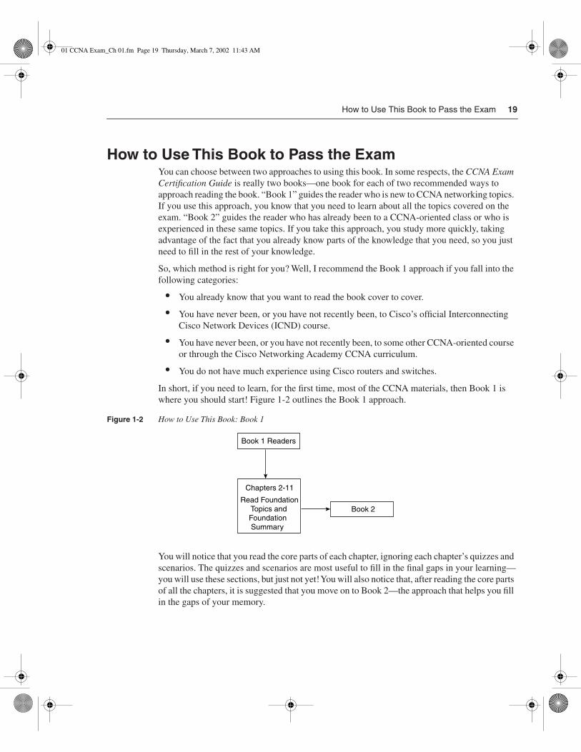
How to Use This Book to Pass the Exam
19
How to Use This Book to Pass the Exam
You can choose between two approaches to using this book. In some respects, the
CCNA Exam Certification Guide
is really two books—one book for each of two recommended ways to approach reading the book. “Book 1” guides the reader who is new to CCNA networking topics. If you use this approach, you know that you need to learn about all the topics covered on the exam. “Book 2” guides the reader who has already been to a CCNA-oriented class or who is experienced in these same topics. If you take this approach, you study more quickly, taking advantage of the fact that you already know parts of the knowledge that you need, so you just need to fill in the rest of your knowledge.
So, which method is right for you? Well, I recommend the Book 1 approach if you fall into the following categories:
•
You already know that you want to read the book cover to cover.
•
You have never been, or you have not recently been, to Cisco’s official Interconnecting Cisco Network Devices (ICND) course.
•
You have never been, or you have not recently been, to some other CCNA-oriented course or through the Cisco Networking Academy CCNA curriculum.
•
You do not have much experience using Cisco routers and switches.
In short, if you need to learn, for the first time, most of the CCNA materials, then Book 1 is where you should start! Figure 1-2 outlines the Book 1 approach.
Figure 1-2
How to Use This Book: Book 1
You will notice that you read the core parts of each chapter, ignoring each chapter’s quizzes and scenarios. The quizzes and scenarios are most useful to fill in the final gaps in your learning—you will use these sections, but just not yet! You will also notice that, after reading the core parts of all the chapters, it is suggested that you move on to Book 2—the approach that helps you fill in the gaps of your memory.
Chapters 2-11
Book 2
Book 1 Readers
Read Foundation Topics and Foundation Summary
01 CCNA Exam_Ch 01.fm Page 19 Thursday, March 7, 2002 11:43 AM

20
Chapter 1: All About the Cisco Certified Network Associate Certification
Book 2 helps you fill in the gaps in your knowledge and skills. Using the Book 2 approach, you will discover what you know and what you do not know, to focus your study on the topics that you have not mastered. Whether you read Book 1 first, or whether you already knew something about networking when you bought this book, Book 2 will help you with the final steps of preparation. You might not realize which topics you need to study and which topics you really already know, but Book 2 guides you through the process. Figure 1-3 outlines the process that I call Book 2.
Figure 1-3
How to Use This Book: Book 2
Chapters 2 through 11 begin with a quiz, which is broken into subdivisions called “quizlets.” If you get a high score, you might simply review the “Foundation Summary” section at the end of the chapter because you already remember a lot. If you score well on one quizlet but low on another, you are directed to the section of the chapter corresponding to the quizlet on which your score was low. If you score less than 50 percent on the overall quiz, you should read the whole chapter. Of course, these are simply guidelines—if you score well but want more review on that topic, read away!
After completing the core chapters (Chapters 2 through 11), you have several options for your next study activity. Because Chapter 12, “Scenarios for Final Preparation,” is the next chapter in succession, it outlines the directions on what to do at the end of your study, right before the test. These same directions are repeated here as well. Figure 1-4 outlines your options for final study for the exam.
"Do I Know This Already?" Quiz
ReadFoundationTopics
LowScore
Read RelatedFoundation TopicsSubsection
ReadFoundationSummary
Q&A Scenarios
Go to NextChapter
MediumScore
HighScore
High Score,Want More
Review
Low QuizletScore
Labs
Book 2 Readers(for Chapters 2-11)
01 CCNA Exam_Ch 01.fm Page 20 Thursday, March 7, 2002 11:43 AM

How to Use This Book to Pass the Exam
21
Figure 1-4
How to Use This Book: Final CCNA Exam Preparation Strategy
As shown, if you want even more final preparation, you can go over the many practice questions located in each chapter and on the CD. All prechapter quiz and chapter-ending questions, with answers, are in Appendix A, “Answers to the ‘Do I Know This Already?’ Quizzes and Q&A Sections.” You can read and review these conveniently located questions and explanations quickly. The CD includes testing software as well as many additional questions in the format of the CCNA exam. These questions should be a valuable resource when performing final preparations.
You should also strongly consider getting some hands-on experience with real routers and switches. I imagine that most of you will want to do that, and those of you who have access to equipment at work can easily do that. For the rest of you, you might have to buy your own gear, use simulators, or rent lab time from companies such as my company, Skyline Computer. Although this book gives a large number of examples, lab scenarios, and lab exercises, there is no substitute for exercising your memory by actually doing real commands on real devices.
Anyone preparing for the CCNA exam can use the guidelines at the beginning of each chapter as a study aid. However, for some additional guidance, the final parts of this chapter give a few strategies for study, based on how you have prepared before buying this book. So, find the section that most closely matches your background in the next few pages, and read about some additional ideas to help you prepare. There is a section for people who have taken ICND, one for those from the Cisco Networking Academies, one for those who will not be taking any classes and have not had much experience, and a final set of strategies for those who will not be taking any classes but who have some experience.
Review, with focus on core CCNA topics andcommands
Review, with focus on breadth of CCNA topics
Review, with focus on hands-on skills
Review particular topic using typical test questions
Take a practice test
Chapter 12scenarios
Read each chapter'sFoundationSummary
DoChapter 13 labs
CD-basedpractice
tests
CD-basedtopicalexam
questions
01 CCNA Exam_Ch 01.fm Page 21 Thursday, March 7, 2002 11:43 AM

22
Chapter 1: All About the Cisco Certified Network Associate Certification
I’ve Taken ICND—Now What?
For starters, you’ve taken the best path to prepare yourself. But let me temper that with the fact that, if you retain more than 50 percent of what you heard in class, you are an extraordinary person! That said, you need the following two strategies:
Strategy 1:
Begin by using the Book 2 approach because you already have learned a lot about the topics on the exam. Each of the core chapters of the book, Chapters 2 through 11, begins with a quiz that helps you assess what you need to study. The chapter then directs you to the appropriate sections in the chapter rather than requiring you to read all of each chapter.
Strategy 2:
Use the directions at the beginning of Chapter 12 to direct your final study before the exam. Chapter 12 is designed to review many concepts, and it outlines a good process for study in the days leading up to your exam.
I’ve Taken the Cisco Networking Academy Courses—Now What?
First of all, congratulations on having the foresight to get into the Cisco Networking Academy program—we need more people who can make this stuff work! (Those of you who didn’t take the Cisco Networking Academy track and are wondering what it’s all about can check outhttp://www.cisco.com/warp/public/779/edu/academy/.) Thankfully, the Networking Academy curriculum actually does a great job of preparing you with the skills and knowledge you need to pass the exam. Unfortunately, your study was probably spread over several semesters, and possibly over a couple of years. So, the details that you do not use frequently might have been forgotten. Now, on to the strategies for success on CCNA:
Strategy 1:
Pull out your Networking Academy curriculum and notes, and reread them. Most people’s memory is exercised better by seeing familiar material—even more so when you wrote it down yourself. If you have ever taken a test and pictured in your mind where the answer was on your page of notes, you can relate.
Strategy 2:
Use the Book 2 approach exactly as described here in Chapter 1. Each of the core chapters of the book, Chapters 2 through 11, begins with a quiz that helps you assess what you need to study. It then directs you to the appropriate sections in the chapter rather than requiring you to read all of each chapter.
Strategy 3:
Make it a point to read the sections of this book that cover some of the theory behind networking and some of the standards. The biggest reason for that is that the Networking Academy is oriented more toward building practical skills than using theoretical knowledge. The suggested sections are listed here:
—
Chapter 5—“Spanning-Tree Protocol”
—
Chapter 7—“Distance Vector Routing Protocols”
Strategy 4: Use the directions at the beginning of Chapter 12 to direct your final study before the exam. Chapter 12 is designed to review many concepts, and it outlines a good process for study in the days leading up to your exam.
01 CCNA Exam_Ch 01.fm Page 22 Thursday, March 7, 2002 11:43 AM

How to Use This Book to Pass the Exam 23
This book should help you sift through the topics and choose the right areas for study, and it also should help you to not waste your time. Congratulations on your Networking Academy work—now add the CCNA certification to take away any doubt in the minds of prospective employers that you know Cisco!
I’m New to Internetworking with Cisco, I Will Not Be Taking the ICND Course, and This Book Is My Only Reference—Now What?
You can pass the CCNA exam without taking any courses. Of course, Cisco wants you to take the recommended courses for all the exams. Its motivation is not to make more money because Cisco does not actually deliver the training; the training partners do. Instead, Cisco truly believes that the more people understand its products, ultimately the happier its customers will be and the more products Cisco will sell. Cisco also believes that the official training is the right way to teach people about Cisco products, so you’re encouraged to take the classes.
Of course, if you use only one reference and it is this one, thank you! However, no single book or course will provide every reader with everything they need, so a second source is usually very beneficial. If you are looking to save money but can afford one more book, the Cisco Press Interconnecting Cisco Network Devices (ICND) book is definitely the best companion. The CCNA exam lists ICND as the main prerequisite course before taking the exam. The Cisco Press ICND book contains the actual ICND course materials, which were given to Cisco Press by Cisco and then converted into book format. The same figures used in the presentations by ICND instructors are used as the figures in the ICND book, with explanations matching what a senior instructor might say when teaching the course. So, if you use one other reference, this is the one!
But, under the assumptions that you are new to Cisco and have only this book, here’s what you should do:
Strategy 1: Start with the Book 1 approach to this book. Resist the temptation to read the quiz questions—they will actually help you more if you wait until later.Strategy 2: After reading Book 1, use the Book 2 approach. Each of the core chapters of the book, Chapters 2 through 11, begins with a quiz that helps you assess what you need to study. It then directs you to the appropriate sections in the chapter rather than requiring you to read all of each chapter.Strategy 3: Use the directions at the beginning of Chapter 12 to direct your final study before the exam. Chapter 12 is designed to review many concepts, and it outlines a good process for study in the days leading up to your exam.Strategy 4: Find any and every opportunity to get your hands on some Cisco routers and switches. You will learn the user interface and command structures much more easily by doing rather than by reading!
01 CCNA Exam_Ch 01.fm Page 23 Thursday, March 7, 2002 11:43 AM

24 Chapter 1: All About the Cisco Certified Network Associate Certification
I’m New to Internetworking with Cisco, I Will Not Be Taking the ICND Course, and I Bought the Interconnecting Cisco Network Devices Book as Well—Now What?
If you have no networking experience at all, start with the ICND book. The CCNA exam lists ICND as the main prerequisite course before taking the exam. The Cisco Press ICND book contains the actual ICND course materials, handed over by Cisco to Cisco Press, and then converted into book format. The same figures used in the presentations by instructors are used as the figures in the book, with explanations matching what a senior instructor might say when teaching the course. So, if you use one other reference, this is the one!
Use the Cisco Press book, Internetworking Technologies Handbook, 3rd Edition, as a reference—it’s got great 4–5 page synopses of what a particular technology is all about. If you want some quick review, and want to get a different perspective on it, use ITH.
After using ICND, you should take the Book 2 approach to using this book.
I’ve Learned a Lot About CCNA Topics Through Experience, but I Will Not Be Taking the ICND Course—Now What?
If you feel that you know a fair amount about CCNA topics already, but you are worried about the topics you simply just have not worked with, this strategy is for you. This book is designed to help you figure out what CCNA topics you need some help with and then help you learn about them. Here’s the simple strategy for you:
Strategy 1: Use the Book 2 approach exactly as described in this chapter. Each of the core chapters of the book, Chapters 2 through 11, begins with a quiz that helps you assess what you need to study. It then directs you to the appropriate sections in the chapter rather than requiring you to read all of each chapter.Strategy 2: Use the directions at the beginning of Chapter 12 to direct your final study before the exam. Chapter 12 is designed to review many concepts, and it outlines a good process for study in the days leading up to your exam.
You should be able to fill in the gaps in your knowledge this way and not risk being bored in the ICND class when it covers the topics you already know.
ConclusionThe CCNA certification is arguably the most important Cisco certification. It certainly is the most popular, is required for several other certifications, and is the first step in distinguishing yourself as someone who has proven knowledge of Cisco.
The CCNA Exam 640-607 Certification Guide is designed to help you attain CCNA certification. This is the CCNA certification book from the only Cisco-authorized publisher.We at Cisco Press believe that this book certainly can help you achieve CCNA certification—but the real work is up to you! I trust that your time will be well spent.
01 CCNA Exam_Ch 01.fm Page 24 Thursday, March 7, 2002 11:43 AM

01 CCNA Exam_Ch 01.fm Page 25 Thursday, March 7, 2002 11:43 AM

Exam Topics in This Chapter
42
Examine router elements (RAM, ROM, CDP,
show
).
43
Manage configuration files from the privileged exec mode.
44
Control router passwords, identification, and banner.
45
Identify the main Cisco IOS Software commands for router startup.
46
Log in to a router in both user and privileged modes.
47
Check an initial configuration using the
setup
command.
48
Use the context-sensitive help facility.
49
Use the command history and editing features.
50
List the commands to load Cisco IOS Software from: Flash memory, a TFTP server, or ROM.
51
Prepare to back up, upgrade, and load a backup Cisco IOS Software image.
52
Prepare the initial configuration of your router and enable IP.
02 CCNA Exam_Ch 02.fm Page 26 Thursday, March 7, 2002 11:44 AM

C
H
A
P
T
E
R
2
Cisco IOS Software Fundamentals
Cisco routers run the Cisco Internetworking Operating System (IOS). So, as you would probably guess, all the questions about implementing something on a router require youto know all about the IOS. Although many topics on the CCNA exam do not relate to the actual implementation on Cisco gear, you probably will not pass the test if you do not know the details of how IOS works.
But do not despair! You need to know about the three main topics of the IOS, and most of this is basic. First, you must know about the IOS command-line interface (CLI)—how to access the interface and how to use it. Next, you need to know how configure the router, even though you might not know what you want to configure yet! Finally, you need to know about upgrading IOS Software; this requires a reboot of the router, so you also need to know what happens during the boot process. By the time you are finished with your CCNA study, the CLI and configuration topics in this chapter will be second nature, for the most part.
The IOS also runs on some Cisco switch models, and it uses CLI. However, in some cases, the IOS CLI on a switch is slightly different than on a router. In fact, the IOS on the 1900 series switches, on which the exam questions are based, is slightly different than on some other Cisco IOS-based switches. This chapter covers the IOS CLI on a router, and Chapter 4, “LANs, Bridges, and Switches,” covers some details of the IOS CLI on LAN switches. Chapter 4 outlines the key differences between the IOS on routers and the IOS on 1900 series switches.
How to Best Use This Chapter
You can choose from two main approaches for using this book, which are described in Chapter 1, “All About the Cisco Certified Network Associate Certification,” and are called “Book 1” and “Book 2.” Book 1 is for readers who need a through background before their final study time; Book 2 is intended for readers who are reviewing and filling in the missing parts of their CCNA knowledge. Using Figure 2-1 as a guide, you should either read the Foundation sections of this chapter or begin with the “Do I Know This Already?” quiz.
02 CCNA Exam_Ch 02.fm Page 27 Thursday, March 7, 2002 11:44 AM

28
Chapter 2: Cisco IOS Software Fundamentals
Figure 2-1
How to Use This Chapter
“Do I Know This Already?” Quiz
The purpose of the “Do I Know This Already?” quiz is to help you decide what parts of this chapter to use. If you already intend to read the entire chapter, you do not necessarily need to answer these questions now.
This 12-question quiz helps you determine how to spend your limited study time. The quiz is sectioned into three smaller four-question “quizlets,” which correspond to the three major topic headings in the chapter. Figure 2-1 outlines suggestions on how to spend your time in this chapter based on your quiz score. Use Table 2-1 to record your scores.
Table 2-1
Scoresheet for Quiz and Quizlets
Quizlet NumberFoundation Topics Section CoveringThese Questions Questions Score
1 Cisco IOS Software and Its User Interface 1 to 4
2 Configuration Processes and the Configuration File 5 to 8
3 Managing Cisco IOS Software Images 9 to 12
All questions 1 to 12
“Do I Know This Already?” Quiz
ReadFoundationTopics
LowScore
Read RelatedFoundation TopicsSubsection
ReadFoundationSummary
Q&A Scenarios
Go to NextChapter
MediumScore
HighScore
High Score,Want More
Review
Low QuizletScore
Labs
Book 2 Readers
Book 1 Readers
Read Foundation Topics and Foundation Summary
Go to Next Chapter
02 CCNA Exam_Ch 02.fm Page 28 Thursday, March 7, 2002 11:44 AM

“Do I Know This Already?” Quiz
29
1
What are the two different names for the router’s mode of operation that, when accessed, enables you to issue commands that could be disruptive to router operations?
____________________________________________________________________
____________________________________________________________________
____________________________________________________________________
2
What command would you use to receive command help if you knew that a
show
command option begins with a
c
but you could not recall the option?
____________________________________________________________________
____________________________________________________________________
____________________________________________________________________
3
After typing
show ip route,
which is the only command that you issued since logging in to the router, you now want to issue the
show ip arp
command. What steps would you take to execute this command by using command-recall keystrokes?
____________________________________________________________________
____________________________________________________________________
____________________________________________________________________
4
What is the name of the user interface mode of operation used when you cannot issue disruptive commands?
____________________________________________________________________
____________________________________________________________________
____________________________________________________________________
5
What configuration command causes the router to require a password from a user at the console? What configuration mode context must you be in? (That is, what command(s) must be typed before this command after entering configuration mode?) List the commands in the order in which they must be typed while in config mode.
____________________________________________________________________
____________________________________________________________________
____________________________________________________________________
6
What does the “NV” stand for in NVRAM?
____________________________________________________________________
____________________________________________________________________
____________________________________________________________________
02 CCNA Exam_Ch 02.fm Page 29 Thursday, March 7, 2002 11:44 AM

30
Chapter 2: Cisco IOS Software Fundamentals
7
Name two commands used to view the configuration that is currently used in a router. Which one is a more recent addition to the IOS?
___________________________________________________________________
___________________________________________________________________
___________________________________________________________________
8
Name two commands used to view the configuration to be used at the next reload of the router. Which one is a more recent addition to the IOS?
___________________________________________________________________
___________________________________________________________________
___________________________________________________________________
9
What two methods could a router administrator use to cause a router to load the IOS stored in ROM?
___________________________________________________________________
___________________________________________________________________
___________________________________________________________________
10
What is the process used to update the contents of Flash memory so that a new IOS in a file called c4500-d-mz.120-5.bin, on TFTP server 128.1.1.1, is copied into Flash memory?
___________________________________________________________________
___________________________________________________________________
___________________________________________________________________
11
Two different IOS files are in a router’s Flash memory: one called c2500-j-l.111-3.bin and one called c2500-j-l.112-14.bin. Which one does the router use when it boots up? How could you force the other IOS file to be used? Without looking at the router configuration, what command could be used to discover which file was used for the latest boot ofthe router?
___________________________________________________________________
___________________________________________________________________
___________________________________________________________________
12
What are the primary purposes of Flash memory in a Cisco router?
___________________________________________________________________
___________________________________________________________________
___________________________________________________________________
02 CCNA Exam_Ch 02.fm Page 30 Thursday, March 7, 2002 11:44 AM

“Do I Know This Already?” Quiz
31
The answers to the “Do I Know This Already?” quiz are found in Appendix A, “Answers to the ‘Do I Know This Already?’ Quizzes and Q&A Sections.” The suggested choices for your next step are as follows:
•
6 or less overall score
—Read the entire chapter. This includes the “Foundation Topics” and “Foundation Summary” sections, the Q&A section, and the scenarios at the end ofthe chapter.
•
2 or less on any quizlet
—Review the subsection(s) of the “Foundation Topics” part of this chapter, based on Table 2-1. Then move on to the “Foundation Summary” section, the Q&A section, and the scenarios at the end of the chapter.
•
7, 8, or 9 overall score
—Begin with the “Foundation Summary” section and then go to the Q&A section and the scenarios at the end of the chapter.
•
10 or more overall score
—If you want more review on these topics, skip to the “Foundation Summary” section and then go to the Q&A section and the scenarios at the end of the chapter. Otherwise, move to the next chapter.
02 CCNA Exam_Ch 02.fm Page 31 Thursday, March 7, 2002 11:44 AM

32
Chapter 2: Cisco IOS Software Fundamentals
Foundation Topics
The Cisco IOS Software Command-Line Interface
42
Examine router elements (RAM, ROM, CDP,
show
).
44
Control router passwords, identification, and banner.
45
Identify the main Cisco IOS Software commands for router startup.
46
Log in to a router in both user and privileged modes.
48
Use the context-sensitive help facility.
49
Use the command history and editing features.
The majority of Cisco routers run Cisco IOS Software, with its familiar command-line interface (CLI). Some routing cards in other devices also run Cisco IOS Software. For example, the Multilayer Switch Feature Card (MSFC) daughter card for the Catalyst 6000 series LAN switches performs routing functions and executes IOS. Understanding the Cisco IOS Software CLI is as fundamental to supporting routers as understanding addition is to being able to do math problems!
The exam topics covered in this section will become second nature to you as you work with Cisco routers and switches more often. In fact, because this book purposefully was written for an audience that already has some training and experience with Cisco routers, several of the details in this chapter might already be ingrained in your memory. If you would like more review, or if you are still new to the IOS, read on—the details in this section are important to using Cisco routers and switches. This chapter reviews such topics as the CLI and how to navigate the IOS command set using help and key sequences for command editing and recall.
Access to the CLI
Cisco uses the acronym CLI to refer to the terminal user command-line interface to the IOS. The term
CLI
implies that the user is typing commands at a terminal, a terminal emulator, or a Telnet connection. Although you can pass the CCNA exam without ever having used the CLI, actually using the CLI will greatly enhance your chances.
02 CCNA Exam_Ch 02.fm Page 32 Thursday, March 7, 2002 11:44 AM

The Cisco IOS Software Command-Line Interface
33
To access the CLI, use one of three methods, as illustrated in Figure 2-2.
Figure 2-2
CLI Access
You access the router through the console, through a dialup device through a modem attached to the auxiliary port, or by using Telnet. In any case, you enter
user exec mode
first. User exec mode, also sometimes called user mode, allows you to look but not break anything. The passwords shown in Figure 2-2 are not defaults—those passwords would be required if the configuration used in Table 2-2 were used. The console, auxiliary, and Telnet passwords are all set separately.
Table 2-2
CLI Password Configuration
Access from . . . Password Type Configuration
Console Console password
line console
0
login
password
faith
Auxiliary Auxiliary password
line aux
0
login
password
hope
Telnet vty password
line vty
0 4
login
password
love
User Mode
Console
Aux
IP net
Telnet
Interfaces
Password: faith
Password: hope
(Short) console cable
Phone line
Password: love
02 CCNA Exam_Ch 02.fm Page 33 Thursday, March 7, 2002 11:44 AM

34
Chapter 2: Cisco IOS Software Fundamentals
Passwords are required for Telnet and auxiliary access as of Cisco IOS Software Release 12.
x
, and the exam is based on Cisco IOS Software Release 12.2. However, there are no preconfigured passwords—therefore, you must configure passwords for Telnet and auxiliary access from the console first.
All Cisco routers have a console port, and most have an auxiliary port. The console port is intended for local administrative access from an ASCII terminal or a computer using a terminal emulator. The auxiliary port, which is missing on a few models of Cisco routers, is intended for asynchronous dial access from an ASCII terminal or terminal emulator; the auxiliary port is often used for dial backup.
This chapter focuses on the process of using the CLI. However, if you see a command in this chapter, you probably should remember it. In this case, the first command in each configuration is a context-setting command, as described later in this chapter. But, as you see, the second and third commands would be ambiguous if we did not supply some additional information, such as whether the
password
command was for the console, aux, or Telnet. The
login
command actually tells the router to display a password prompt. The
password
commands specify the text password to be typed by the user to gain access. Typically, all three passwords have the same value because they all let you get into user mode.
Several concurrent Telnet connections to a router are allowed. The
line vty
0 4
command signifies that this configuration applies to vtys (virtual teletypes/terminals) 0 through 4. Only these five vtys are allowed by the IOS, unless it is an IOS for a dial access server, such as a Cisco AS5300. All five vtys typically have the same password, which is handy because users connecting to the router through Telnet cannot choose which vty they get.
User exec mode is one of two command exec modes in the IOS user interface.
Enable
mode (also known as
privileged
mode or
privileged
exec mode) is the other. Enable mode is so named because the
enable
command is used to reach this mode, as shown in Figure 2-3; privileged mode earns its name because powerful, or privileged, commands can be executed there.
Figure 2-3
User and Privileged Modes
Usermode
Privilegedmode*
router>enablepassword: zzzzz router#
router#disablerouter>
*Also calledenable mode
Console
Aux
Telnet
02 CCNA Exam_Ch 02.fm Page 34 Thursday, March 7, 2002 11:44 AM

The Cisco IOS Software Command-Line Interface
35
CLI Help Features
If you printed the IOS Command Reference documents, you would end up with a stack of paper several feet tall. No one should expect to memorize all the commands—and no one does in real life, either. Several very easy, convenient tools can be used to help you remember commands and then also save you time typing. As you progress through your Cisco certifications, the exam will cover progressively more commands. However, the only Cisco exam that covers the methods of getting command help is the CCNA exam. So, the following details are important in real life as well as for cramming for the exam.
Table 2-3 summarizes command-recall help options available at the CLI. Note that in the first column, “Command” represents any command. Likewise, “parm” represents a command’s parameter. For instance, the third row lists “command ?,” which means that commands such as
show ?
and
copy ?
would list help for the
show
and
copy
commands, respectively.
When you type the
?
, IOS’s CLI reacts immediately; that is, you don’t need to press the Enter key or any other keys. The router also redisplays what you typed before the
?
, to save you some keystrokes. If you press Enter immediately after the
?
, IOS tries to execute the command with only the parameters that you have typed so far.
“Command” represents any command, not the word
command
. Likewise, “parm” represents a command’s parameter, not the word
parameter
.
The information supplied by using help depends on the CLI mode. For example, when
?
is typed in user mode, the commands allowed only in privileged exec mode are not displayed. Also, help is available in configuration mode; only configuration commands are displayed in that mode of operation.
Table 2-3
Cisco IOS Software Command Help
What You Type The Help You Get
? Help for all commands available in this mode.
Help Text describing how to get help. No actual command help is given.
Command ? Text help describing all the first parameter options for the command.
com? A list of commands that start with “com.”
Command parm? This style of help lists all parameters beginning with “parm.” (Notice that no spaces exist between “parm” and the ?.)
command parm<Tab> If you press the Tab key midword, the CLI will either spell the rest of this parameter at the command line or do nothing. If the CLI does nothing, it means that this string of characters represents more than one possible next parameter, so the CLI does not know which to spell out.
command parm1 ? If a space is inserted before the question mark, the CLI lists all the next parameters and gives a brief explanation of each.
02 CCNA Exam_Ch 02.fm Page 35 Thursday, March 7, 2002 11:44 AM

36 Chapter 2: Cisco IOS Software Fundamentals
IOS stores the commands that you type in a history buffer, storing ten commands by default. You can change the history size with the terminal history size x command, where x is the number of commands for the CLI to recall; this can be set to a value between 0 and 256. You can then retrieve commands so that you do not have to retype the commands. Table 2-4 lists the commands used to manipulate previously typed commands.
Table 2-4 Key Sequences for Command Edit and Recall
Keyboard Command What You Get
Up arrow or Ctrl-p This displays the most recently used command. If it is pressed again, the next most recent command appears until the history buffer is exhausted. (The p stands for previous.)
Down arrow or Ctrl-n If you have gone too far back into the history buffer, these keys will go forward, in order, to the more recently typed commands. (The n is for next.)
Left arrow or Ctrl-b This moves the cursor backward in the currently displayed command without deleting characters. (The b stands for back.)
Right arrow or Ctrl-f This moves the cursor forward in the currently displayed command without deleting characters. (The f stands for forward.)
Backspace This moves the cursor backward in the currently displayed command, deleting characters.
Ctrl-a This moves the cursor directly to the first character of the currently displayed command.
Ctrl-e This moves the cursor directly to the end of the currently displayed command.
Esc-b This moves the cursor back one word in the currently displayed command.
Esc-f This moves the cursor forward one word in the currently displayed command.
Ctrl-r This creates a new command prompt, followed by all the characters typed since the last command prompt was written. This is particularly useful if system messages confuse the screen and it is unclear what you have typed so far.
02 CCNA Exam_Ch 02.fm Page 36 Thursday, March 7, 2002 11:44 AM

The Cisco IOS Software Command-Line Interface 37
Syslog and debug
Start Extra Credit
IOS creates messages when different events occur and, by default, sends them to the console. These messages are called syslog messages. If you have used the console of a router for any length of time, you likely have noticed these messages—and when they are frequent, you probably became a little frustrated.
The router also generates messages that are treated like syslog messages in response to some troubleshooting tasks that you might perform. The debug command is one of the key diagnostic tools for troubleshooting difficult problems on a router. debug enables monitoring points in the IOS and generates messages that describe what the IOS is doing and seeing. When any debug command option is enabled, the router processes the messages with the same logic as other syslog messages. Beware: Some debug options create so many messages that the IOS cannot process them all, possibly crashing the IOS.
End Extra Credit
NOTE The no debug all command disables all debugs. Before enabling an unfamiliar debug command option, issue a no debug all and then issue the debug that you want to use; then quickly retrieve the no debug all command. If the messages are voluminous, press Enter immediately, executing the no debug all command to try to prevent the router from crashing by immediately disabling all debugs.
You might or might not be interested in seeing the messages as they occur. The console port always receives syslog messages. When you Telnet to the router, however, no syslog messages are seen unless you issue the terminal monitor command. This command simply means that this terminal is monitoring syslog messages. Another alternative for viewing syslog messages is to have the IOS record the syslog messages in a buffer in RAM and then use the show logging command to display the messages. For Telnet users, having the messages buffered using the global config command logging buffered is particularly useful. Because Telnet users do not get syslog messages by default anyway, these users can wait and look at syslog messages when desired. Finally, the logging synchronous line-configuration subcommand can be used for the console and vtys to tell the router to wait until the last command output is displayed before showing any syslog messages onscreen. That provides a little less interruption.
02 CCNA Exam_Ch 02.fm Page 37 Thursday, March 7, 2002 11:44 AM

38 Chapter 2: Cisco IOS Software Fundamentals
Syslog messages also can be sent to another device. Two alternatives exist: sending the messages to a syslog server, and sending the messages as SNMP traps to a management station. The logging host command, where host is the IP address or host name of the syslog server,is used to enable sending messages to the external server. After SNMP is configured, thesnmp-server enable traps tells the IOS to forward traps, including syslog messages.
Figure 2-4 summarizes the flow of syslog messages, including debug messages. For a more detailed view of syslog messages, including restricting messages based on message severity, refer to the Cisco IOS Software documentation CD manual called “Troubleshooting Commands.”
Figure 2-4 Syslog Message Flows
Usertyped
terminalmonitor?
Yes
To console
Console
To each
telnet user
Isloggingbuffered
configured?
Yes
Islogging
hostnameconfigured?
Yes
Issnmp-serverenable trapconfigured?
Yes
IOS sends messages tosyslog server; Server IPaddress or hostname Isdefined with logging command
IOS sends messages toSNMP manager using traps
IOS copies messagesinto RAM: can be seenUsing show logging
Systemgeneratesmessage
Telnet
02 CCNA Exam_Ch 02.fm Page 38 Thursday, March 7, 2002 11:44 AM

Configuring Cisco IOS Software 39
Configuring Cisco IOS Software
43 Manage configuration files from the privileged exec mode.
47 Check an initial configuration using the setup command.
53 Prepare the initial configuration of your router and enable IP.
You must understand how to configure a Cisco router to succeed on the exam—or to succeed in supporting Cisco routers. This section covers the basic configuration processes, including the concept of a configuration file and the locations in which the configuration files can be stored.
As mentioned in Chapter 1, configuration mode is another mode for the Cisco CLI, similar to user mode and privileged mode. User mode allows commands that are not disruptive to be issued, with some information being displayed to the user. Privileged mode supports a superset of commands compared to user mode, including commands that might harm the router. However, none of the commands in user or privileged mode changes the configuration of the router. Configuration mode is another mode in which configuration commands are typed. Figure 2-5 illustrates the relationships among configuration mode, user exec mode, and privileged exec mode.
Figure 2-5 CLI Configuration Mode versus Exec Modes
Commands typed in configuration mode update the active configuration file. These changes to the configuration occur immediately each time you press the Enter key at the end of a command. Be careful when you type in a configuration command!
Configuration mode itself contains a multitude of subcommand modes. Context-setting commands move you from one configuration subcommand mode to another. These context-setting commands tell the router the topic about which you will type the next few configuration commands. More importantly, they tell the router what commands to list when you ask for help.
User exec mode Privileged execmode
Configurationmode
RAM(Active config)
Each command
enable
in succession
Ctrl-Zor exit
config t
02 CCNA Exam_Ch 02.fm Page 39 Thursday, March 7, 2002 11:44 AM

40 Chapter 2: Cisco IOS Software Fundamentals
After all, the whole reason for these contexts is to make online help more convenient and clear for you. So, if you are confused now, hang on—the next sample will clarify what I mean.
NOTE Context setting is not a Cisco term—it’s just a term used here to help make sense of configuration mode.
The interface command is the most commonly used context-setting configuration command. As an example, the CLI user could enter interface configuration mode after typing the interface ethernet 0 configuration command. Command help in Ethernet interface configuration mode displays only commands that are useful when configuring Ethernet interfaces. Commands used in this context are called subcommands—or, in this specific case, interface subcommands. If you have significant experience using the CLI in configuration mode, much of this will be second nature. From a CCNA exam perspective, recalling whether popular commands are global commands or subcommands will be useful, but you should really focus on the particular commands covered here. As a side effect, you will learn whether the commands are global configuration commands or subcommands.
No set rules exist for what commands are global commands or subcommands. Generally, however, when multiple instances of a parameter can be set in a single router, the command used to set the parameter is likely a configuration subcommand. Items that are set once for the entire router are likely global commands. For instance, the hostname command is a global command because there is only one host name per router. The interface ethernet 0 command is a global configuration command because there is only one such interface in this router. Finally, the ip address command is an interface subcommand that sets the IP address on the interface; each interface will have a different IP address.
Use Ctrl-z from any part of configuration mode (or use the exit command from global configuration mode) to exit configuration mode and return to privileged exec mode. The configuration mode end command also exits from any point in the configuration mode back to privileged exec mode. The exit commands from submodes or contexts of configuration mode back up one level toward global configuration mode.
Example Configuration ProcessExample 2-1 illustrates how the console password is defined; provides banner, host name, prompt, and interface descriptions; and shows the finished configuration. The lines beginning with “!” are comment lines that highlight significant processes or command lines within the example. The show running-config command output also includes comment lines with just a “!” to make the output more readable—many comment lines in the examples in this book were added to explain the meaning of the configuration. You should remember the process as well as these particular commands for the CCNA exam.
02 CCNA Exam_Ch 02.fm Page 40 Thursday, March 7, 2002 11:44 AM

Configuring Cisco IOS Software 41
Example 2-1 Configuration Process Example
User Access Verification
Password: Router>enablePassword: Router #configure terminalRouter(config)#enable password luRouter(config)#line console 0Router(config-line)#loginRouter(config-line)#password ciscoRouter(config-line)#hostname CritterCritter(config)#prompt EmmaEmma(config)#interface serial 1Emma(config-if)#description this is the link to AlbuquerqueEmma(config-if)#exitEmma(config)#exitEmma#Emma#show running-configBuilding configuration...
Current configuration:!version 12.2 934 bytes ! Version of IOS on router, automatic command
service timestamps debug uptimeservice timestamps log uptimeno service password-encryption!hostname Critterprompt Emma!enable password lu !ip subnet-zerono ip domain-lookup !interface Serial0!interface Serial1 description this is the link to Albuquerque!interface Ethernet0!ip classlessno ip http serverline con 0 password cisco
continues
02 CCNA Exam_Ch 02.fm Page 41 Thursday, March 7, 2002 11:44 AM

42 Chapter 2: Cisco IOS Software Fundamentals
Several differences exist between user and privileged mode, compared to configuration mode. The configure terminal command is used to move into configuration mode. The command prompt changes based on the configuration subcommand mode that you are in. Plus, typing a ? in configuration mode gives you help just on configuration commands.
When you change from one configuration mode to another, the prompt changes. Example 2-2 repeats the same example as in Example 2-1, but with annotations for what is happening.
login!line aux 0line vty 0 4!end
Example 2-2 Configuration Process with Annotations
User Access Verification
Password: Router>enable !In user mode, then you type the enable commandPassword: Router #configure terminal!In privileged mode, using the configure terminal command to enter globalRouter(config)#enable password lu!The enable password command is a global command – so the prompt stays as a global command promptRouter(config)#line console 0!line console changes the context to console line configuration modeRouter(config-line)#login!login is a console subcommand, so the prompt remains the sameRouter(config-line)#password cisco!password is also a console sub-commandRouter(config-line)#hostname Critter!hostname is a global command, so it is used, and the mode changes back to global config mode Critter(config)#prompt Emma!prompt is a global command, so the prompt stays as a global command mode promptEmma(config)#interface serial 1!interface changes contexts to interface subcommand modeEmma(config-if)#description link to Albuquerque!description is a sub-command in interface config mode, so prompt stays the sameEmma(config-if)#exit!exit backs up one mode towards globalEmma(config)#exit!exit in global mode exits back to privileged mode
Example 2-1 Configuration Process Example (Continued)
02 CCNA Exam_Ch 02.fm Page 42 Thursday, March 7, 2002 11:44 AM

Configuring Cisco IOS Software 43
Router Memory, Processors, and InterfacesThe configuration file contains the configuration commands that you have typed, as well as some configuration commands entered by default by the router. The configuration file can be stored in a variety of places, including two inside a router. The router has a couple of other types of memory as well:
• RAM—Sometimes called DRAM for dynamic random-access memory, RAM is used by the router just as it is used by any other computer: for working storage. The running or active configuration file is stored here.
• ROM—This type of memory (read-only memory) stores a bootable IOS image, which is not typically used for normal operation. ROM contains the code that is used to boot the router until the router knows where to get the full IOS image, or as a backup bootable image in case there are problems.
• Flash memory—Either an EEPROM or a PCMCIA card, Flash memory stores fully functional IOS images and is the default location where the router gets its IOS at boot time. Flash memory also can be used to store configuration files on some Cisco routers.
• NVRAM—Nonvolatile RAM stores the initial or startup configuration file.
All these types of memory, except RAM, are permanent memory. No hard disk or diskette storage exists on Cisco routers. Figure 2-6 summarizes the use of memory in Cisco routers.
Figure 2-6 Cisco Router Memory Types
The processors in the routers vary from model to model. Although knowledge of them is not specifically listed as a requirement for the CCNA exam, some reference to terminology is useful. In most routers, only one processor option is available; thus, you would not order a specific processor type or card. The exception to this is the 7200 and 7500 families of routers. For instance, on the 7500 series, you choose either a Route Switch Processor 1 (RSP-1), RSP-2, or RSP-4 processor. In any case, all 7200 and 7500 routers, as well as most of the other Cisco router families, run IOS. This commonality enables Cisco to formulate exams, such as CCNA, that cover the IOS features without having to cover many hardware details.
The terminology used to describe the physical interfaces used for routing packets and bridging frames varies based on the model of router. Also, the types of interfaces available change over time because of new technology. For example, Packet over SONET and voice interfaces are relatively recent additions to the product line. However, some confusion exists about what to call the actual cards that house the physical interfaces. Table 2-5 summarizes the terminology that might be referred to on the test.
RAM
(Workingmemory andrunningconfiguration)
Flash
(Cisco IOSSoftware)
ROM
(Basic CiscoIOS Software)
NVRAM
(Startupconfiguration)
02 CCNA Exam_Ch 02.fm Page 43 Thursday, March 7, 2002 11:44 AM

44 Chapter 2: Cisco IOS Software Fundamentals
But there is hope! Cisco IOS Software always uses the term interfaces rather than any of the other terms, so IOS commands familiar on one platform will be familiar on another. Some nuances are involved in numbering the interfaces, however. In some smaller routers, the interface number is a single number. However, with some other families of routers, the interface is numbered first with the slot in which the card resides, followed by a slash and then the port number on that card. For example, port 3 on the card in slot 2 would be interface 2/3. Numbering starts with 0 for card slots and 0 for ports on any card. In some cases, the interface is defined by three numbers: first the card slot, then the daughter card (typically called a port adapter), and then a number for the physical interface on the port adapter. The 2600 and 3600 families also use a slot/port numbering scheme.
In this book, the single-digit interface numbers are used simply for consistency and readability.
If you want to dig deeper, you might want to read about processors and interfaces in the Cisco Product Catalog (http://www.cisco.com/univercd/cc/td/doc/pcat/).
Managing Configuration FilesThe CCNA exam requires that you be able to distinguish between the configuration file used at startup and the active, running configuration file. The startup configuration file is in NVRAM; the other file, which is in RAM, is the one that the router uses during operation. When the router first comes up, the router copies the stored configuration file from NVRAM into RAM, so the running and startup configuration files are identical at that point. Also, exterior to the router, configuration files can be stored as ASCII text files anywhere using TFTP or FTP.
Example 2-3 demonstrates the basic interaction between the two files. In this example, the show running-config and show startup-config commands are used. These commands display the currently used, active, running configuration, and the stored, startup configuration used when the router boots, respectively. The full command output is not shown; instead, you can see only a brief excerpt including the host command, which will be changed several times. (Notes are included inside the example that would not appear if doing these commands on a real router.)
Table 2-5 Samples of Router Interface Terminology
Model Series
What Cisco IOS Software Calls Interfaces
What the Product Catalog Calls the Cards with the Interfaces on Them
2500 Interface Modules and WAN interface cards
2600/3600 Interface Network modules and WAN interface cards
4500 Interface Network processor modules
7200 Interface Port adapters and service adapters
7500 Interface Interface processors and versatile interface processors with port adapters
02 CCNA Exam_Ch 02.fm Page 44 Thursday, March 7, 2002 11:44 AM

Configuring Cisco IOS Software 45
If you reload the router now, the host name would revert back to hannah. However, if you want to keep the changed host name of jessie, you would use the command copy running-config startup-config, which overwrites the current startup-config file with what is currently in the running configuration file.
The copy command can be used to copy files in a router, most typically a configuration file, or a new version of the IOS Software. The most basic method for moving configuration files in and out of a router is by using a TFTP server. The copy command is used to move configuration files among RAM, NVRAM, and a TFTP server. The files can be copied between any pair, as Figure 2-7 illustrates.
Figure 2-7 Locations for Copying and Results from Copy Operations
Example 2-3 Configuration Process Example
hannah#show running-config… (lines omitted)hostname hannah… (rest of lines omitted)
hannah#show startup-config… (lines omitted)hostname hannah… (rest of lines omitted)hannah#configure terminalhannah(config)#hostname jessiejessie(config)#exitjessie#show running-config… (lines omitted)hostname jessie… (rest of lines omitted – notice that the running configuration reflects the changed hostname)jessie# show startup-config… (lines omitted)hostname hannah… (rest of lines omitted – notice that the changed configuration is not shown in the startup config)
RAM NVRAMcopy tftp running-config copy running-config startup-config
copy startup-config running-configcopy running-config tftp
copy tftp startup-config
copy startup-config tftp
TFTP
02 CCNA Exam_Ch 02.fm Page 45 Thursday, March 7, 2002 11:44 AM

46 Chapter 2: Cisco IOS Software Fundamentals
The commands can be summarized as follows:
copy {tftp | running-config | startup-config} {tftp | running-config | startup-config}
The first parameter is the “from” location; the next one is the “to” location. (Of course, choosing the same option for both parameters is not allowed.)
The copy command does not always replace the existing file that it is copying. Any copy command option moving a file into NVRAM or a TFTP server replaces the existing file—that’s the easy, straightforward action. Effectively, any copy into RAM works just as if you typed the commands in the “from” configuration file in the order listed in the config file.
So, who cares? Well, we do. If you change the running config and then decide that you want to revert to what’s in the startup-config file, the only way to guarantee that is to issue the reload command, which reloads, or reboots, the router.
Two key commands can be used to erase the contents of NVRAM. The write erase command is the older command, and the erase startup-config command is the newer command. Both simply erase the contents of the NVRAM configuration file. Of course, if the router is reloaded at this point, there will be no initial configuration.
Viewing the Configuration and Old-Style Configuration CommandsOnce upon a time, commands that were used to display and move configuration files among RAM, NVRAM, and TFTP did not use easy-to-recall parameters such as startup-configand running-config. In fact, most people could not remember the commands or got the different ones confused. Figure 2-8 shows both the old and the new commands used toview configurations.
Figure 2-8 Configuration show Commands
Initial Configuration (Setup Mode)Setup mode leads a router administrator to a basic router configuration by using questions that prompt the administrator for basic configuration parameters. Instead of using setup mode, a Cisco router can be configured using the CLI in configuration mode. In fact, most networking personnel do not use setup at all, but new users sometimes like to use setup mode, particularly until they become more familiar with the CLI configuration mode.
RAM(active)
NVRAM
write term
show config show startup-config
show running-config
old new
02 CCNA Exam_Ch 02.fm Page 46 Thursday, March 7, 2002 11:44 AM

Configuring Cisco IOS Software 47
NOTE If you plan to work with Cisco routers much, you should become accustomed with the CLI configuration mode discussed earlier. Setup mode allows only basic configuration. Both topics are covered on the CCNA exam.
Figure 2-9 and Example 2-4 describe the process used by setup mode. Setup mode is most frequently used when the router boots, and it has no configuration in NVRAM. Setup mode also can be entered by using the setup command from privileged mode.
Figure 2-9 Getting into Setup Mode
Example 2-4 shows a screen capture of using setup mode after booting a router with no configuration in NVRAM.
Example 2-4 Router Setup Configuration Mode
--- System Configuration Dialog ---
Would you like to enter the initial configuration dialog? [yes/no]: yesAt any point you may enter a question mark '?' for help.Use ctrl-c to abort configuration dialog at any prompt.Default settings are in square brackets '[]'.Basic management setup configures only enough connectivity
Turn on router
Move newconfigurationinto NVRAM
Complete IOSinitialization
Is NVRAMempty?
Do youwant to
enter setupmode?
Yes
Yes
No
No
Answer the questionsin setup mode
Copy startup-config torunning-config
continues
02 CCNA Exam_Ch 02.fm Page 47 Thursday, March 7, 2002 11:44 AM
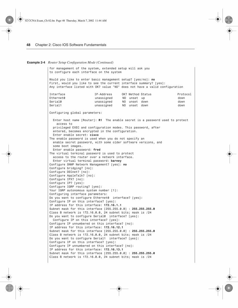
48 Chapter 2: Cisco IOS Software Fundamentals
for management of the system, extended setup will ask youto configure each interface on the system
Would you like to enter basic management setup? [yes/no]: noFirst, would you like to see the current interface summary? [yes]: Any interface listed with OK? value "NO" does not have a valid configuration
Interface IP-Address OK? Method Status ProtocolEthernet0 unassigned NO unset up down Serial0 unassigned NO unset down down Serial1 unassigned NO unset down down
Configuring global parameters:
Enter host name [Router]: R1 The enable secret is a password used to protect access to privileged EXEC and configuration modes. This password, after entered, becomes encrypted in the configuration. Enter enable secret: cisco The enable password is used when you do not specify an enable secret password, with some older software versions, and some boot images. Enter enable password: fred The virtual terminal password is used to protect access to the router over a network interface. Enter virtual terminal password: barney Configure SNMP Network Management? [yes]: no Configure bridging? [no]: Configure DECnet? [no]: Configure AppleTalk? [no]: Configure IPX? [no]: Configure IP? [yes]: Configure IGRP routing? [yes]: Your IGRP autonomous system number [1]: Configuring interface parameters:Do you want to configure Ethernet0 interface? [yes]: Configure IP on this interface? [yes]: IP address for this interface: 172.16.1.1 Subnet mask for this interface [255.255.0.0] : 255.255.255.0 Class B network is 172.16.0.0, 24 subnet bits; mask is /24Do you want to configure Serial0 interface? [yes]: Configure IP on this interface? [yes]: Configure IP unnumbered on this interface? [no]: IP address for this interface: 172.16.12.1 Subnet mask for this interface [255.255.0.0] : 255.255.255.0 Class B network is 172.16.0.0, 24 subnet bits; mask is /24Do you want to configure Serial1 interface? [yes]: Configure IP on this interface? [yes]: Configure IP unnumbered on this interface? [no]: IP address for this interface: 172.16.13.1 Subnet mask for this interface [255.255.0.0] : 255.255.255.0 Class B network is 172.16.0.0, 24 subnet bits; mask is /24
Example 2-4 Router Setup Configuration Mode (Continued)
02 CCNA Exam_Ch 02.fm Page 48 Thursday, March 7, 2002 11:44 AM

Configuring Cisco IOS Software 49
Setup behaves like Example 2-2 illustrates, whether setup was reached by booting with an empty NVRAM or whether the setup privileged exec command was used. First, the router asks whether you want to enter the “initial configuration dialog.” Answering y or yes puts you in setup mode.
The following configuration command script was created:
hostname R1enable secret 5 $1$VOLh$pkIe0Xjx2sgjgZ/Y6Gt1s.enable password fredline vty 0 4password barneyno snmp-server!no bridge 1no decnet routingno appletalk routingno ipx routingip routing !interface Ethernet0ip address 172.16.1.1 255.255.255.0no mop enabled!interface Serial0ip address 172.16.12.1 255.255.255.0no mop enabled!interface Serial1ip address 172.16.13.1 255.255.255.0no mop enableddialer-list 1 protocol ip permitdialer-list 1 protocol ipx permit!router igrp 1redistribute connectednetwork 172.16.0.0!end
[0] Go to the IOS command prompt without saving this config.[1] Return back to the setup without saving this config.[2] Save this configuration to nvram and exit.
Enter your selection [2]: 2Building configuration...[OK]Use the enabled mode 'configure' command to modify this configuration.Press RETURN to get started!
Example 2-4 Router Setup Configuration Mode (Continued)
02 CCNA Exam_Ch 02.fm Page 49 Thursday, March 7, 2002 11:44 AM

50 Chapter 2: Cisco IOS Software Fundamentals
When you are finished with setup, you select one of three options for what to do next. Option 2 tells the router to save the configuration to NVRAM and exit; this option is used in Example 2-4. The router places the config in both NVRAM and RAM. This is the only operation in the IOS that changes both configuration files to include the same contents based on a single action by the user. Options 0 and 1 tell the router to ignore the configuration that you just entered and to either exit to the command prompt (option 1) or start over gain with setup (option 1).
Upgrading Cisco IOS Software and the Cisco IOS Software Boot Process
50 List the commands to load Cisco IOS Software from: Flash memory, a TFTP server, or ROM.
51 Prepare to back up, upgrade, and load a backup Cisco IOS Software image.
Engineers need to know how to upgrade the IOS to move to a later release. Typically, a router has one IOS image in Flash memory, and that is the IOS that is used. (The term IOS image simply refers to a file containing the IOS.) The upgrade process might include steps such as copying a newer IOS image into Flash memory, configuring the router to tell it which IOS image to use, and deleting the old one when you are confident that the new release works well.
A router decides what IOS image to use when the router boots. Also, to upgrade to a new IOS or back out to an older IOS, you must reload the router. So, it’s a convenient time to cover the boot sequence and some of the related issues.
Finally, password recovery is covered in this section. Password recovery is less likely to be on the CCNA exam than some other topics, but, guess what—it requires a reboot of the router, so now is a good time to cover it.
Upgrading an IOS Image into Flash MemoryIOS files typically are stored in Flash memory. Flash memory is rewriteable, permanent storage, which is ideal for storing files that need to be retained when the router loses power. Also, because there are no moving parts, there is a smaller chance of failure as compared with disk drives, which provides better availability. As you will read soon, IOS can be placed on an external TFTP server, but using an external server typically is done for testing—in production, practically every Cisco router loads an IOS stored in the only type of large, permanent memory, and that is Flash memory.
02 CCNA Exam_Ch 02.fm Page 50 Thursday, March 7, 2002 11:44 AM
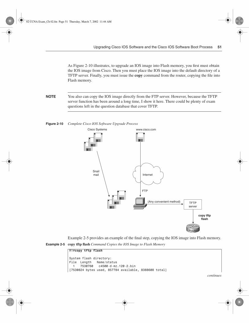
Upgrading Cisco IOS Software and the Cisco IOS Software Boot Process 51
continues
As Figure 2-10 illustrates, to upgrade an IOS image into Flash memory, you first must obtain the IOS image from Cisco. Then you must place the IOS image into the default directory of a TFTP server. Finally, you must issue the copy command from the router, copying the file into Flash memory.
NOTE You also can copy the IOS image directly from the FTP server. However, because the TFTP server function has been around a long time, I show it here. There could be plenty of exam questions left in the question database that cover TFTP.
Figure 2-10 Complete Cisco IOS Software Upgrade Process
Example 2-5 provides an example of the final step, copying the IOS image into Flash memory.
Example 2-5 copy tftp flash Command Copies the IOS Image to Flash Memory
R1#copy tftp flash
System flash directory:File Length Name/status 1 7530760 c4500-d-mz.120-2.bin [7530824 bytes used, 857784 available, 8388608 total]
Internet
FTP
Router
copy tftpflash
Snailmail
(Any convenient method) TFTPserver
Cisco Systems www.cisco.com
02 CCNA Exam_Ch 02.fm Page 51 Thursday, March 7, 2002 11:44 AM

52 Chapter 2: Cisco IOS Software Fundamentals
During this process of copying the IOS image into Flash memory, the router will need to discover several important facts:
1 What is the IP address or host name of the TFTP server?
2 What is the name of the file?
3 Is space available for this file in Flash memory?
4 Do you want the router to erase the old files?
The router will prompt you for answers, as necessary. Afterward, the router erases Flash memory as needed, copies the file, and then verifies that the checksum for the file shows that no errors occurred in transmission. The show flash command then can be used to verify the contents of Flash memory (see Example 2-6). (The show flash output can vary among router families.) Before the new IOS is used, however, the router must be reloaded.
Address or name of remote host [255.255.255.255]? 134.141.3.33Source file name? c4500-d-mz.120-5.binDestination file name [c4500-d-mz.120-5.bin]? Accessing file c4500-d-mz.120-5.bin ' on 134.141.3.33...Loading c4500-d-mz.120-5.bin from 134.141.3.33 (via TokenRing0): ! [OK]
Erase flash device before writing? [confirm]Flash contains files. Are you sure you want to erase? [confirm]
Copy 'c4500-d-mz.120-5.bin ' from server as 'c4500-d-mz.120-5.bin ' into Flash WITH erase? [yes/no]yErasing device... eeeeeeeeeeeeeeeeeeeeeeeeeeeeeeee ...erasedLoading c4500-d-mz.120-5.bin from 134.141.3.33 (via TokenRing0): !!!!!!!!!!!!!!!!!!!!!!!!!!!!!!!!!!!!!!!!!!!!!!!!!!!!!!!!!!!!!!!!!!!!!!!!!!!!!!!! !!!!!!!!!!!!!!!!!!!!!!!!!!!!!!!!!!!!!!!!!!!!!!!!!!!!!!!!!!!!!!!!!! (leaving out lots of exclamation points…)[OK – 7530760/8388608 bytes]
Verifying checksum... OK (0xA93E)Flash copy took 0:04:26 [hh:mm:ss]R1#
Example 2-6 Verifying Flash Memory Contents with the show flash Command
fred#show flash
System flash directory:File Length Name/status 1 6181132 c4500-d-mz.120-5.bin[4181196 bytes used, 4207412 available, 8388608 total]8192K bytes of processor board System flash (Read ONLY)
Example 2-5 copy tftp flash Command Copies the IOS Image to Flash Memory (Continued)
02 CCNA Exam_Ch 02.fm Page 52 Thursday, March 7, 2002 11:44 AM
Upgrading Cisco IOS Software and the Cisco IOS Software Boot Process 53
In some cases, Flash memory could be in read-only mode. That is the case when a router loads only part of the IOS into RAM, to conserve RAM. Other parts of the IOS file are kept in Flash memory (Flash memory access time is much slower than RAM’s). In this case, if Flash memory must be erased to make room for a new image, the IOS could not continue to run. So, if the router is running from a portion of IOS in Flash memory, the router first must be booted using IOS in ROM. Then the Flash memory will be in read/write mode and the erase and copy processes can be accomplished. The copy tftp flash command in later releases of the IOS actually performs the entire process for you. In earlier releases, you had to boot the router from ROM and then issue the copy tftp flash command.
The Cisco IOS Software Boot SequenceCisco routers perform the same types of tasks that a typical computer performs when you power it on or reboot (reload) it. Of course, most of us do not think about these details very often. The router performs some somewhat obvious steps, with one of those being tricky—namely, the process of choosing the location of the software to load and use in the router. And that software might not be IOS!
The boot process follows this basic litany:
1 The router performs a power-on self-test (POST) to discover and verify the hardware.
2 The router loads and runs bootstrap code from ROM.
3 The router finds the IOS or other software and loads it.
4 The router finds the configuration file and loads it into running config.
All routers attempt all four steps each time that the router is powered on or reloaded. The POST code and functions cannot be changed by the router administrator. The location of the bootstrap code, the IOS to load, and the configuration file can be changed by the administrator—but you almost always use the default location for the bootstrap code (ROM) and for the initial configuration (NVRAM). So, the location of IOS or other software is the only part that typically is changed.
Three categories of operating systems can be loaded into the router:
• The full-function IOS image that you have been introduced to in this chapter.
• A limited-function IOS that resides in ROM.
• A different non-IOS operating system that is also stored in ROM, and this can be loaded. This operating system, called ROM Monitor, is used for two purposes—for low-level debugging and for password recovery. Unless you are performing password recovery, you would seldom use ROMMON mode.
02 CCNA Exam_Ch 02.fm Page 53 Thursday, March 7, 2002 11:44 AM

54 Chapter 2: Cisco IOS Software Fundamentals
Table 2-6 lists the three operating system categories and their main functions.
So, you need to tell the router whether to use ROMMON, the limited-function IOS, or the full-featured IOS. Of course, most of the time you use the full-featured IOS in Flash memory. However, you might want to use IOS that resides on a TFTP server, or there could be multiple IOS images in Flash memory—and all of these options are configurable.
Two configuration tools tell the router what OS to load. First, the configuration register tells the router whether to use a full-featured IOS, ROMMON, or the limited-feature IOS, which is also called RXBOOT mode. The configuration register is a 16-bit software register in the router, and its value is set using the config-register global configuration command. (Some older routers had a hardware configuration register with jumpers on the processor card, to set bits to a value of 0 or 1.) Figure 2-11 shows an example binary breakdown of the default value for the configuration register, which is hexadecimal 2102.
Figure 2-11 Binary Version of Configuration Register, Value Hex 2102
The boot field is the name of the low-order 4 bits of the configuration register. This field can be considered a 4-bit value, represented as a single hexadecimal digit. (Cisco represents hexadecimal values by preceding the hex digit(s) with 0x—for example, 0xA would mean a single hex digit A.) If the boot field is hex 0, ROMMON is loaded. If the boot field is hex 1, RXBOOT mode is used. For anything else, it loads a full-featured IOS. But which one?
Table 2-6 Three OS Categories for Routers
Operating System Location Where It Is Stored Purpose
Full-featured IOS Typically in Flash memory; can be on TFTP server
Full-featured, normal IOS used in production.
Limited-function IOS ROM Basic IP connectivity, used when Flash memory is broken and you need IP connectivity to copy a new IOS into Flash memory. Called RXBOOT mode.
ROMMON ROM Low-level debugging, usually by the Cisco TAC and for password recovery. Called ROM Monitor mode.
15 14 13 120 0 1 0
11 10 9 80 0 0 1
7 6 5 40 0 0 0
3 2 1 00 0 1 0
02 CCNA Exam_Ch 02.fm Page 54 Thursday, March 7, 2002 11:44 AM

Upgrading Cisco IOS Software and the Cisco IOS Software Boot Process 55
The second method used to determine where the router tries to obtain an IOS image is through the use of the boot system configuration command. If the configuration register calls for a full-featured IOS (boot field 2-F), the router reads the configuration file for boot system commands. If there are no boot system commands, the router takes the default action, which is to load the first file in Flash memory. Table 2-7 summarizes the use of the configuration register and the boot system command at initialization time.
Table 2-7 boot system Command
Value of Boot Field Boot System Commands Result
0x0 Ignored if present ROMMON is loaded.
0x1 Ignored if present IOS from ROM is loaded, also known as RXBOOT mode.
0x2-0xF No boot command The first IOS file in Flash memory is loaded; if that fails, the router broadcasts looking for an IOS on a TFTP server. If that fails, IOS from ROM is loaded.
0x2-0xF boot system ROM IOS from ROM is loaded.
0x2-0xF boot system flash The first file from Flash memory is loaded.
0x2-0xF boot system flash filename IOS with the name filename is loaded from Flash memory.
0x2-0xF boot system tftp filename 10.1.1.1 IOS with the name filename is loaded from the TFTP server.
0x2-0xF Multiple boot system commands, any variety
An attempt occurs to load IOS based on the first boot command in configuration. If that fails, the second boot command is used, and so on, until one is successful.
02 CCNA Exam_Ch 02.fm Page 55 Thursday, March 7, 2002 11:44 AM

56 Chapter 2: Cisco IOS Software Fundamentals
Password Recovery
Start Extra Credit
The password-recovery process relies on the fact that the configuration register can be used to make the router ignore the NVRAM configuration when the router is reloaded. The router will be up, but with a default configuration; this allows a console user to log in, enter privileged mode, and change any encrypted passwords or view any unencrypted passwords. However, there is a “chicken and the egg” problem—to cause the router to ignore NVRAM at boot time, the configuration register must be changed. To do that, you must be in privileged mode—and if you were already there, you could reset any encrypted passwords or view any unencrypted ones. It seems to be a vicious circle.
ROMMON will allow you to change the configuration register without knowing any passwords or even booting the IOS. To enter ROMMON mode, press the Break key during the first 60 seconds after power-on of the router. Then you must set bit 6 in the configuration register to binary 1, which is done by setting the entire config register with a four-digit hexadecimal value. For example, hex 2142 is identical to hex 2102, except that bit 6 is binary 1. Knowing how to reset the config register enables you to boot the router (ignoring NVRAM), allowing the console user to see or change the unencrypted or encrypted passwords, respectively.
The process is slightly different for different models of routers, although the concepts are identical. Table 2-8 outlines the process for each type of router. For more information, seehttp://www.cisco.com/warp/public/474/.
End Extra Credit
Table 2-8 Password Recovery
Step Function
How to Do This for 1600, 2600, 3600, 4500, 7200, 7500
How to Do This for 2000, 2500, 3000, 4000, 7000
1 Turn the router off and then back on again.
Use the power switch. Same as other routers.
2 Press the Break key within the first 60 seconds.
Find the Break key on your console device’s keyboard.
Same as other routers.
3 Change the configuration register so that bit 6 is 1.
Use the ROMMON command confreg, and answer the prompts.
Use the ROMMON command o/r 0x2142.
4 Cause the router to load IOS.
Use the ROMMON reload command or, if unavailable, power off and on.
Use the ROMMON command initialize.
02 CCNA Exam_Ch 02.fm Page 56 Thursday, March 7, 2002 11:44 AM

Upgrading Cisco IOS Software and the Cisco IOS Software Boot Process 57
A few nuances need further explanation. First, the confreg ROMMON command prompts you with questions that correspond to the functions of the bits in the configuration register. When the prompt asks, “Ignore system config info[y/n]?”, it is asking you about bit 6. Entering yes sets the bit to 1. The rest of the questions can be defaulted. The last confreg question asks, “Change boot characteristics[y/n]?”, which asks whether you want to change the boot field of the config register. You don’t really need to change it, but the published password-recovery algorithm lists that step, which is the only reason that it is mentioned here. Just changing bit 6 to 1 is enough to get the router booted and you into privileged mode to find or change the passwords.
Step Function
How to Do This for 1600, 2600, 3600, 4500, 7200, 7500
How to Do This for 2000, 2500, 3000, 4000, 7000
5 Avoid using setup mode, which will be prompted for at the console.
Just say no. Same as other routers.
6 Enter privileged mode at console.
Press Enter and use the enable command (no password required).
Same as other routers.
7 Assuming that you still want to use the configuration in NVRAM, copy it to the running config.
copy startup-config running-config
copy startup-config running-config
8 View startup config to see unencrypted passwords.
Use the exec command show startup-config.
Same as other routers.
9 Use the appropriate config commands to reset encrypted commands.
For example, use enable secret xyz123 command to set the enable secret password.
Same as other routers.
10 Change the config register back to its original value.
Use the config command config-reg 0x2102.
Same as other routers.
11 Reload the router after saving the configuration.
Use the copy running-config startup-config and reload commands.
Same as other routers.
Table 2-8 Password Recovery (Continued)
02 CCNA Exam_Ch 02.fm Page 57 Thursday, March 7, 2002 11:44 AM

58 Chapter 2: Cisco IOS Software Fundamentals
Foundation Summary
The “Foundation Summary” is a collection of tables and figures that provide a convenient review of many key concepts in this chapter. For those of you already comfortable with the topics in this chapter, this summary could help you recall a few details. For those of you who just read this chapter, this review should help solidify some key facts. For any of you doing your final preparation before the exam, these tables and figures will be a convenient way to review the day before the exam.
The console, auxiliary, and Telnet passwords are all set separately, as shown in Table 2-9.
Table 2-10 lists the commands used to manipulate previously typed commands.
Table 2-9 CLI Password Configuration
Access from . . . Password Type Configuration
Console Console password line console 0
login
password faith
Auxiliary Auxiliary password line aux 0
login
password hope
Telnet vty password line vty 0 4
login
password love
Table 2-10 Key Sequences for Command Edit and Recall
Keyboard Command What the User Gets
Up arrow or Ctrl-p This displays the most recently used command. If it is pressed again, the next most recent command appears until the history buffer is exhausted. (The p stands for previous.)
Down arrow or Ctrl-n If you have gone too far back into the history buffer, these keys willgo forward, in order, to the more recently typed commands. (The nis for next.)
Left arrow or Ctrl-b This moves the cursor backward in the currently displayed command without deleting characters. (The b stands for back.)
Right arrow or Ctrl-f This moves the cursor forward in the currently displayed command without deleting characters. (The f stands for forward.)
02 CCNA Exam_Ch 02.fm Page 58 Thursday, March 7, 2002 11:44 AM

Foundation Summary 59
Figure 2-12 illustrates the relationships among configuration mode, user exec mode, and privileged exec mode.
Figure 2-12 CLI Configuration Mode versus Exec Modes
Routers have four types of memory:
• RAM—Sometimes called DRAM for dynamic random-access memory, RAM is used by the router just as it is used by any other computer: for working storage. The running or active configuration file is stored here.
• ROM—This type of memory (read-only memory) stores a bootable IOS image, which is not typically used for normal operation. ROM contains the code that is used to boot the router until the router knows where to get the full IOS image, or as a backup bootable image in case there are problems.
Keyboard Command What the User Gets
Backspace This moves the cursor backward in the currently displayed command, deleting characters.
Ctrl-a This moves the cursor directly to the first character of the currently displayed command.
Ctrl-e This moves the cursor directly to the end of the currently displayed command.
Esc-b This moves the cursor back one word in the currently displayed command.
Esc-f This moves the cursor forward one word in the currently displayed command.
Ctrl-r This creates a new command prompt, followed by all the characters typed since the last command prompt was written. This is particularly useful if system messages confuse the screen and it is unclear what you have typed so far.
Table 2-10 Key Sequences for Command Edit and Recall (Continued)
User exec mode Privileged exec mode
Configurationmode
RAM(Active config)
Each command
enable
in succession
Ctrl-Zor exit
config t
02 CCNA Exam_Ch 02.fm Page 59 Thursday, March 7, 2002 11:44 AM

60 Chapter 2: Cisco IOS Software Fundamentals
• Flash memory—Either an EEPROM or a PCMCIA card, Flash memory stores fully functional IOS images and is the default location where the router gets its IOS at boot time. Flash memory also can be used to store configuration files on some Cisco routers.
• NVRAM—Nonvolatile RAM stores the initial or startup configuration file.
All these types of memory, except RAM, are permanent memory. No hard disk or diskette storage exists on Cisco routers. Figure 2-13 summarizes the use of memory in Cisco routers.
Figure 2-13 Cisco Router Memory Types
The copy command is used to move configuration files among RAM, NVRAM, and a TFTP server. The files can be copied between any pair, as Figure 2-14 illustrates.
Figure 2-14 Locations for Copying and Results from Copy Operations
The commands can be summarized as follows:
copy {tftp | running-config | startup-config} {tftp | running-config | startup-config}
The first parameter is the “from” location; the next one is the “to” location. (Of course, choosing the same option for both parameters is not allowed.)
Figure 2-15 shows both the old and the new commands used to view configurations.
RAM
(Workingmemory andrunningconfiguration)
Flash
(Cisco IOSSoftware)
ROM
(Basic CiscoIOS Software)
NVRAM
(Startupconfiguration)
RAM NVRAMcopy tftp running-config copy running-config startup-config
copy startup-config running-configcopy running-config tftp
copy tftp startup-config
copy startup-config tftp
TFTP
02 CCNA Exam_Ch 02.fm Page 60 Thursday, March 7, 2002 11:44 AM
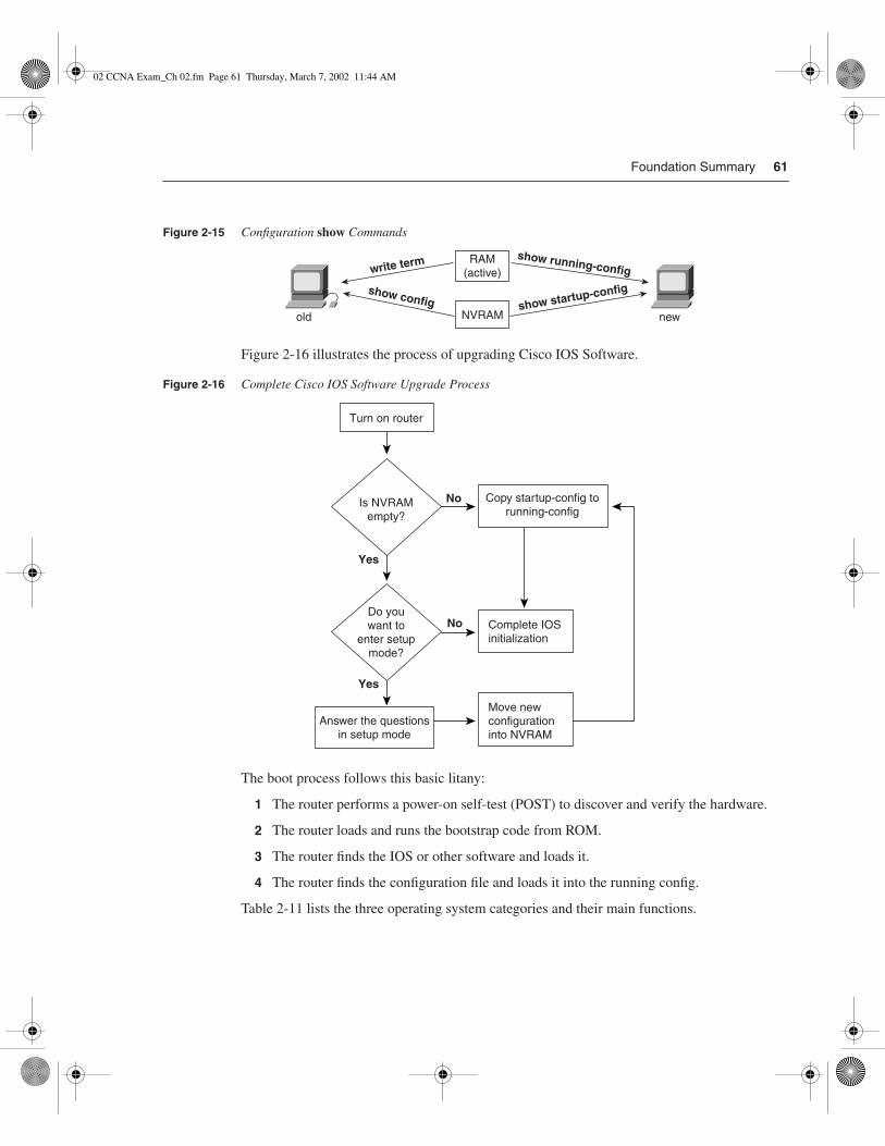
Foundation Summary 61
Figure 2-15 Configuration show Commands
Figure 2-16 illustrates the process of upgrading Cisco IOS Software.
Figure 2-16 Complete Cisco IOS Software Upgrade Process
The boot process follows this basic litany:
1 The router performs a power-on self-test (POST) to discover and verify the hardware.
2 The router loads and runs the bootstrap code from ROM.
3 The router finds the IOS or other software and loads it.
4 The router finds the configuration file and loads it into the running config.
Table 2-11 lists the three operating system categories and their main functions.
RAM(active)
NVRAM
write term
show config show startup-config
show running-config
old new
Turn on router
Move newconfigurationinto NVRAM
Complete IOSinitialization
Is NVRAMempty?
Do youwant to
enter setupmode?
Yes
Yes
No
No
Answer the questionsin setup mode
Copy startup-config torunning-config
02 CCNA Exam_Ch 02.fm Page 61 Thursday, March 7, 2002 11:44 AM

62 Chapter 2: Cisco IOS Software Fundamentals
Figure 2-17 shows an example binary breakdown of the default value for the configuration register, which is hexadecimal 2102.
Figure 2-17 Binary Version of Configuration Register, Value Hex 2102
Table 2-12 summarizes the use of the configuration register and the boot system command at initialization time.
Table 2-11 Three OS Categories for Routers
Operating System Location Where It Is Stored Purpose
Full-featured IOS Typically in Flash memory, can be on TFTP server
Full-featured, normal IOS used in production
Limited-function IOS ROM Basic IP connectivity, used when Flash memory is broken and you need IP connectivity to copy a new IOS into Flash memory. Called RXBOOT mode.
ROMMON ROM Low-level debugging, usually by the Cisco TAC and for password recovery. Called ROM Monitor mode.
15 14 13 120 0 1 0
11 10 9 80 0 0 1
7 6 5 40 0 0 0
3 2 1 00 0 1 0
02 CCNA Exam_Ch 02.fm Page 62 Thursday, March 7, 2002 11:44 AM

Foundation Summary 63
Table 2-12 boot system Command
Value of Boot Field Boot System Commands Result
0x0 Ignored if present ROMMON is loaded.
0x1 Ignored if present IOS from ROM is loaded, also known as RXBOOT mode.
0x2-0xF No boot command The first IOS file in Flash memory is loaded; if that fails, the router broadcasts looking for an IOS on a TFTP server. If that fails, IOS from ROM is loaded.
0x2-0xF boot system ROM IOS from ROM is loaded.
0x2-0xF boot system flash The first file from Flash memory is loaded.
0x2-0xF boot system flash filename IOS with the name filename is loaded from Flash memory.
0x2-0xF boot system tftp filename 10.1.1.1 IOS with the name filename is loaded from the TFTP server.
0x2-0xF Multiple boot system commands, any variety
An attempt occurs to load the IOS based on the first boot command in configuration. If that fails, the second boot command is used, and so on, until one is successful.
02 CCNA Exam_Ch 02.fm Page 63 Thursday, March 7, 2002 11:44 AM

64 Chapter 2: Cisco IOS Software Fundamentals
Q&A
As mentioned in Chapter 1, the questions and scenarios in this book are more difficult than what you should experience on the actual exam. The questions do not attempt to cover more breadth or depth than the exam; however, they are designed to make sure that you know the answer. Rather than allowing you to derive the answer from clues hidden inside the question itself, the questions challenge your understanding and recall of the subject. Questions from the “Do I Know This Already?” quiz from the beginning of the chapter are repeated here to ensure that you have mastered the chapter’s topic areas. Hopefully, these questions will help limit the number of exam questions on which you narrow your choices to two options and then guess. Make sure to use the CD and take the simulated exams.
The answers to these questions can be found in Appendix A.
1 What are the two names for the router’s mode of operation that, when accessed, enables you to issue commands that could be disruptive to router operations?
______________________________________________________________________
______________________________________________________________________
______________________________________________________________________
2 What are three methods of logging on to a router?
______________________________________________________________________
______________________________________________________________________
______________________________________________________________________
3 What is the name of the user interface mode of operation used when you cannot issue disruptive commands?
______________________________________________________________________
______________________________________________________________________
______________________________________________________________________
4 Can the auxiliary port be used for anything besides remote modem user access to a router? If so, what other purpose can it serve?
______________________________________________________________________
______________________________________________________________________
______________________________________________________________________
02 CCNA Exam_Ch 02.fm Page 64 Thursday, March 7, 2002 11:44 AM

Q&A 65
5 How many console ports can be installed on a Cisco 7500 router?
_______________________________________________________________________
_______________________________________________________________________
_______________________________________________________________________
6 What command would you use to receive command help if you knew that a show command option begins with a c but you cannot recall the option?
_______________________________________________________________________
_______________________________________________________________________
_______________________________________________________________________
7 While you are logged in to a router, you issue the command copy ? and get a response of “Unknown command, computer name, or host.” Offer an explanation for why this error message appears.
_______________________________________________________________________
_______________________________________________________________________
_______________________________________________________________________
8 Is the number of retrievable commands based on the number of characters in each command, or is it simply a number of commands, regardless of their size?
_______________________________________________________________________
_______________________________________________________________________
_______________________________________________________________________
9 How can you retrieve a previously used command? (Name two ways.)
_______________________________________________________________________
_______________________________________________________________________
_______________________________________________________________________
10 After typing show ip route, which is the only command that you typed since logging in to the router, you now want to issue the show ip arp command. What steps would you take to execute this command by using command-recall keystrokes?
_______________________________________________________________________
_______________________________________________________________________
_______________________________________________________________________
02 CCNA Exam_Ch 02.fm Page 65 Thursday, March 7, 2002 11:44 AM

66 Chapter 2: Cisco IOS Software Fundamentals
11 After typing show ip route 128.1.1.0, you now want to issue the command show ip route 128.1.4.0. What steps would you take to do so, using command-recall and command-editing keystrokes?
______________________________________________________________________
______________________________________________________________________
______________________________________________________________________
12 What configuration command causes the router to require a password from a user at the console? What configuration mode context must you be in? (That is, what command(s) must be typed before this command after entering configuration mode?) List the commands in the order in which they must be typed while in config mode.
______________________________________________________________________
______________________________________________________________________
______________________________________________________________________
13 What configuration command is used to tell the router the password that is required at the console? What configuration mode context must you be in? (That is, what command(s) must you type before this command after entering configuration mode?) List the commands in the order in which they must be typed while in config mode.
______________________________________________________________________
______________________________________________________________________
______________________________________________________________________
14 What are the primary purposes of Flash memory in a Cisco router?
______________________________________________________________________
______________________________________________________________________
______________________________________________________________________
15 What is the intended purpose of NVRAM memory in a Cisco router?
______________________________________________________________________
______________________________________________________________________
______________________________________________________________________
16 What does the “NV” stand for in NVRAM?
______________________________________________________________________
______________________________________________________________________
______________________________________________________________________
02 CCNA Exam_Ch 02.fm Page 66 Thursday, March 7, 2002 11:44 AM

Q&A 67
17 What is the intended purpose of RAM in a Cisco router?
_______________________________________________________________________
_______________________________________________________________________
_______________________________________________________________________
18 What is the main purpose of ROM in a Cisco router?
_______________________________________________________________________
_______________________________________________________________________
_______________________________________________________________________
19 What configuration command would be needed to cause a router to use an IOS image named c2500- j-l.112-14.bin on TFTP server 128.1.1.1 when the router is reloaded? If you forgot the first parameter of this command, what steps must you take to learn the correct parameters and add the command to the configuration? (Assume that you are not logged in to the router when you start.)
_______________________________________________________________________
_______________________________________________________________________
_______________________________________________________________________
20 What command sets the password that would be required after typing the enable command? Is that password encrypted by default?
_______________________________________________________________________
_______________________________________________________________________
_______________________________________________________________________
21 To have the correct syntax, what must you add to the following configuration command:
_______________________________________________________________________
_______________________________________________________________________
_______________________________________________________________________
22 Name two commands that affect the text used as the command prompt.
_______________________________________________________________________
_______________________________________________________________________
_______________________________________________________________________
02 CCNA Exam_Ch 02.fm Page 67 Thursday, March 7, 2002 11:44 AM

68 Chapter 2: Cisco IOS Software Fundamentals
23 When using setup mode, you are prompted at the end of the process for whether you want to use the configuration parameters that you just typed in. Which type of memory is this configuration stored in if you type yes?
______________________________________________________________________
______________________________________________________________________
______________________________________________________________________
24 What two methods could a router administrator use to cause a router to load IOS storedin ROM?
______________________________________________________________________
______________________________________________________________________
______________________________________________________________________
25 What could a router administrator do to cause a router to load file xyz123.bin from TFTP server 128.1.1.1 upon the next reload? Is there more than one way to accomplish this?
______________________________________________________________________
______________________________________________________________________
______________________________________________________________________
26 What is the process used to update the contents of Flash memory so that a new IOS in a file called c4500-d-mz.120-5.bin on TFTP server 128.1.1.1 is copied into Flash memory?
______________________________________________________________________
______________________________________________________________________
______________________________________________________________________
27 Name three possible problems that could prevent the command boot system tftp c2500-j-l.112- 14.bin 128.1.1.1 from succeeding.
______________________________________________________________________
______________________________________________________________________
______________________________________________________________________
02 CCNA Exam_Ch 02.fm Page 68 Thursday, March 7, 2002 11:44 AM

Q&A 69
28 Two different IOS files are in a router’s Flash memory: one called c2500-j-l.111-3.bin and one called c2500-j-l.112-14.bin. Which one does the router use when it boots up? How could you force the other IOS file to be used? Without looking at the router configuration, what command could be used to discover which file was used for the latest boot of the router?
_______________________________________________________________________
_______________________________________________________________________
_______________________________________________________________________
29 Is the password required at the console the same one that is required when Telnet is used to access a router?
_______________________________________________________________________
_______________________________________________________________________
_______________________________________________________________________
30 Which IP routing protocols could be enabled using setup?
_______________________________________________________________________
_______________________________________________________________________
_______________________________________________________________________
31 Name two commands used to view the configuration to be used at the next reload of the router. Which one is a more recent addition to the IOS?
_______________________________________________________________________
_______________________________________________________________________
_______________________________________________________________________
32 Name two commands used to view the configuration that is currently used in a router. Which one is a more recent addition to IOS?
_______________________________________________________________________
_______________________________________________________________________
_______________________________________________________________________
33 True or false: The copy startup-config running-config command always changes the currently used configuration for this router to exactly match what is in the startup configuration file. Explain.\
_______________________________________________________________________
_______________________________________________________________________
_______________________________________________________________________
02 CCNA Exam_Ch 02.fm Page 69 Thursday, March 7, 2002 11:44 AM

70 Chapter 2: Cisco IOS Software Fundamentals
Scenarios
Scenario 2-1Compare the following output in Example 2-7 and Example 2-8. Example 2-7 was gathered at 11:00 a.m., 30 minutes earlier than in Example 2-8. What can you definitively say happened to this router during the intervening half hour?
Example 2-7 1:00 a.m. show running-config
hostname Gorno!enable password cisco!interface Serial0 ip address 134.141.12.1 255.255.255.0!interface Serial1 ip address 134.141.13.1 255.255.255.0!interface Ethernet0 ip address 134.141.1.1 255.255.255.0!router rip network 134.141.0.0!line con 0 password cisco loginline aux 0line vty 0 4 password cisco login
Example 2-8 11:30 a.m. show running-config
hostname SouthernSiberiaprompt Gorno!enable secret $8df003j56ske92enable password cisco!interface Serial0 ip address 134.141.12.1 255.255.255.0!interface Serial1 ip address 134.141.13.1 255.255.255.0!interface Ethernet0 ip address 134.141.1.1 255.255.255.0
02 CCNA Exam_Ch 02.fm Page 70 Thursday, March 7, 2002 11:44 AM

Scenario 2-1 71
Questions on Scenario 2-11 During the process of changing the configuration in Scenario 2-1, the command prompt
temporarily was SouthernSiberia(config)#. What configuration commands, and in what order, could have changed the configuration as shown and allowed the prompt to temporarily be SouthernSiberia(config)#?
2 Assuming that Figure 2-18 is complete, what effect does the no cdp enable command have?
Figure 2- 18 Siberian Enterprises’ Sample Network
3 What effect would the no enable password cisco command have at this point?
no cdp enable!router rip network 134.141.0.0!line con 0 password cisco loginline aux 0line vty 0 4 password cisco login
Example 2-8 11:30 a.m. show running-config (Continued)
Gorno Nova
Barnaul
S0S0
S0
S1S1
S1
02 CCNA Exam_Ch 02.fm Page 71 Thursday, March 7, 2002 11:44 AM

72 Chapter 2: Cisco IOS Software Fundamentals
Scenario 2-2Example 2-9 shows that the running-config command was executed on the Nova router.
Questions on Scenario 2-21 If this is all the information that you have, what IOS do you expect will be loaded when
the user reloads Nova?
2 Examine the following command output in Example 2-10, taken immediately before the user is going to type the reload command. What IOS do you expect will be loaded?
Example 2-9 Configuration of Router Nova
hostname Novabanner # This is the router in Nova Sibiersk; Dress warmly before entering! #!boot system tftp c2500-js-113.bin 134.141.88.3boot system flash c2500-j-l.111-9.binboot system rom!enable password cisco!interface Serial0 ip address 134.141.12.2 255.255.255.0!interface Serial1 ip address 134.141.23.2 255.255.255.0!interface TokenRing0 ip address 134.141.2.2 255.255.255.0!router rip network 134.141.0.0!line con 0 password cisco loginline aux 0line vty 0 4 password cisco login
02 CCNA Exam_Ch 02.fm Page 72 Thursday, March 7, 2002 11:44 AM

Scenario 2-2 73
3 Now examine the following show flash command in Example 2-11, which was issued immediately after the show ip route command in Example 2-10 but before the user issued the reload command. What IOS do you think would be loaded in this case?
4 Now examine the configuration in Example 2-12. Assume that there is now a route to 134.141.88.0 and that the file c2500-j-l.111-9.bin is an IOS image in Flash memory. What IOS do you expect will be loaded now?
Example 2-10 show ip route Command Output for Nova
Nova#show ip routeCodes: C - connected, S - static, I - IGRP, R - RIP, M - mobile, B - BGP D - EIGRP, EX - EIGRP external, O - OSPF, IA - OSPF inter area N1 - OSPF NSSA external type 1, N2 - OSPF NSSA external type 2 E1 - OSPF external type 1, E2 - OSPF external type 2, E - EGP i - IS-IS, L1 - IS-IS level-1, L2 - IS-IS level-2, ia - IS-IS inter area * - candidate default, U - per-user static route, o - ODR P - periodic downloaded static route
Gateway of last resort is not set
134.141.0.0/24 is subnetted, 6 subnetsC 134.141.2.0 is directly connected, TokenRing0R 134.141.3.0 [120/1] via 134.141.23.3, 00:00:15, Serial1R 134.141.1.0 [120/1] via 134.141.12.1, 00:00:20, Serial0C 134.141.12.0 is directly connected, Serial0R 134.141.13.0 [120/1] via 134.141.12.1, 00:00:20, Serial0 [120/1] via 134.141.23.3, 00:00:15, Serial1C 134.141.23.0 is directly connected, Serial1
Example 2-11 show flash Command Output for Nova
Nova#show flash4096K bytes of flash memory sized on embedded flash.File name/status 0 c2500-j-l.111-3.bin[682680/4194304 bytes free/total]
02 CCNA Exam_Ch 02.fm Page 73 Thursday, March 7, 2002 11:44 AM

74 Chapter 2: Cisco IOS Software Fundamentals
Example 2-12 show running-config Command Output for Router Nova
hostname Novabanner # This is the router in Nova Sibiersk; Dress warmly before entering! #!boot system tftp c2500-js-113.bin 134.141.88.3boot system flash c2500-j-l.111-9.bin!enable password cisco!interface Serial0 ip address 134.141.12.2 255.255.255.0!interface Serial1 ip address 134.141.23.2 255.255.255.0!interface Ethernet0 ip address 134.141.2.2 255.255.255.0!router rip network 134.141.0.0!line con 0 password cisco loginline aux 0line vty 0 4 password cisco login!config-register 0x2101
02 CCNA Exam_Ch 02.fm Page 74 Thursday, March 7, 2002 11:44 AM

Scenario 2-1 Answers 75
Answers to Scenarios
Scenario 2-1 AnswersIn Scenario 2-1, the following commands were added to the configuration:
• enable secret as a global command.
• prompt as a global command.
• no cdp enable as an Ethernet0 subcommand.
• The hostname command also was changed.
The scenario questions’ answers are as follows:
1 If the host name was changed to SouthSiberia first and the prompt command was added next, the prompt would have temporarily been SouthSiberia. Configuration commands are added to the RAM configuration file immediately and are used. In this case, when the prompt command was added, it caused the router to use Gorno, not the then-current host name SouthernSiberia, as the prompt.
2 No practical effect takes place. Because no other Cisco CDP–enabled devices are on that Ethernet, CDP messages from Gorno are useless. So, the only effect is to lessen the overhead on that Ethernet in a very small way.
3 No effect takes place, other than cleaning up the configuration file. The enable password is not used if an enable secret is configured.
02 CCNA Exam_Ch 02.fm Page 75 Thursday, March 7, 2002 11:44 AM

76 Chapter 2: Cisco IOS Software Fundamentals
Scenario 2-2 AnswersThe answers to the questions in Scenario 2-2 are as follows:
1 The first boot system statement would be used: boot system tftp c2500-js-113.bin 134.141.88.3.
2 The boot system flash command would be used. The TFTP boot presumably would fail because there is not currently a route to the subnet of which the TFTP server is a part. It is reasonable to assume that a route would not be learned 2 minutes later when the router had reloaded. So, the next boot system command (flash) would be used.
3 The boot system ROM command would be used. Because there is no file in Flash memory called c2500-j- l.111-9.bin, the boot from Flash memory would fail as well, leaving only one boot command.
4 IOS from ROM would be loaded because of the configuration register. If the configuration register boot field is set to 0x1, boot system commands are ignored. So, having a route to the 134.141.88.0/ 24 subnet and having c2500-j-l.111-9.bin in Flash memory does not help.
02 CCNA Exam_Ch 02.fm Page 76 Thursday, March 7, 2002 11:44 AM

02 CCNA Exam_Ch 02.fm Page 77 Thursday, March 7, 2002 11:44 AM

Exam Topics in This Chapter
5
Describe data-link and network addresses, and identify key differences between them.
6
Define and describe the function of a MAC address.
7
List the key internetworking functions of the OSI network layer.
8
Identify at least three reasons why the industry uses alayered model.
9
Describe the two parts of network addressing, and then identify the parts in specific protocol address examples.
10
Define and explain the five conversion steps of data encapsulation.
11
Describe connection-oriented network service and connectionless network service, and identify theirkey differences.
12
Identify the parts in specific protocol address examples.
03 CCNA Exam_Ch 03.fm Page 78 Thursday, March 7, 2002 11:46 AM

C
H
A
P
T
E
R
3
OSI Reference Model and Layered Communication
In years past, the need to understand the Open System Interconnection (OSI) reference model for networking grew rapidly. The U.S. government passed laws requiring vendors to support OSI software on their systems; if vendors did not offer this support, the government would no longer buy the systems. Several vendors even predicted that the global Internet would evolve toward using the OSI protocols instead of TCP/IP. As the century turns, however, OSI has been implemented on a much smaller scale than predicted. Today, no one even sells a full-complement OSI software suite. However, some components of the OSI model are popularly implemented today. For example, OSI network service access point (NSAP) network layer addresses often are used for signaling in Asynchronous Transfer Mode (ATM) networks. In short, OSI was a great idea that never fully made it to market.
So, why have a whole chapter on OSI? As a CCNA, you’ll be expected to learn and interpret new technologies and protocols. The OSI seven-layer reference model is an excellent point of reference for describing the concepts and functions behind these new technologies and protocols. References to Layer 2 switching and Layer 3 switching, which are popular topics today, refer to the comparison between Layers 2 and 3 of the OSI model. Cisco courses make generous use of the OSI model as a reference for comparison with other network protocol implementations. So, this chapter will not actually help you understand OSI fully, but it will discuss OSI functions in comparison with popularly implemented protocols.
How to Best Use This Chapter
By taking the following steps, you can make better use of your study time:
•
Keep your notes and the answers for all your work with this book in one place, for easy reference.
•
Take the “Do I Know This Already?” quiz, and write down your answers. Studies show that retention is significantly increased through writing down facts and concepts, even if you never look at the information again.
•
Use the diagram in Figure 3-1 to guide you to the next step.
03 CCNA Exam_Ch 03.fm Page 79 Thursday, March 7, 2002 11:46 AM

80
Chapter 3: OSI Reference Model and Layered Communication
Figure 3-1
How to Use This Chapter
“Do I Know This Already?” Quiz
The purpose of the “Do I Know This Already?” quiz is to help you decide what parts of this chapter to use. If you already intend to read the entire chapter, you do not necessarily need to answer these questions now.
This 16-question quiz helps you determine how to spend your limited study time. The quiz is sectioned into four smaller four-question “quizlets,” which correspond to the four major headings in the “Foundation Topics” section of the chapter. Figure 3-1 outlines suggestions on how to spend your time in this chapter. Use Table 3-1 to record your score.
Table 3-1
Scoresheet for Quiz and Quizlets
Quizlet Number
Foundation Topics Section CoveringThese Questions Questions Score
1 The OSI, TCP/IP, and NetWare Protocol Architectures 1 to 4
2 OSI Transport Layer Functions 5 to 8
3 OSI Data Link Layer Functions 9 to 12
4 OSI Network Layer Functions 13 to 16
All questions 1 to 16
“Do I Know This Already?” Quiz
ReadFoundationTopics
LowScore
Read RelatedFoundation TopicsSubsection
ReadFoundationSummary
Q&A Scenarios
Go to NextChapter
MediumScore
HighScore
High Score,Want More
Review
Low QuizletScore
Labs
Book 2 Readers Book 1 Readers
Read FoundationTopics andFoundationSummary
Go to NextChapter
03 CCNA Exam_Ch 03.fm Page 80 Thursday, March 7, 2002 11:46 AM

“Do I Know This Already?” Quiz
81
1
Name the seven layers of the OSI model.
_______________________________________________________________________
_______________________________________________________________________
_______________________________________________________________________
2
What is the main purpose(s) of Layer 3?
_______________________________________________________________________
_______________________________________________________________________
_______________________________________________________________________
3
What is the main purpose(s) of Layer 2?
_______________________________________________________________________
_______________________________________________________________________
_______________________________________________________________________
4
What OSI layer typically encapsulates using both a header and a trailer?
_______________________________________________________________________
_______________________________________________________________________
_______________________________________________________________________
5
Describe the features required for a protocol to be considered connectionless.
_______________________________________________________________________
_______________________________________________________________________
_______________________________________________________________________
6
Describe the features required for a protocol to be considered connection-oriented.
_______________________________________________________________________
_______________________________________________________________________
_______________________________________________________________________
7
In a particular error-recovering (reliable) protocol, the sender sends three frames, labeled 2, 3, and 4. On its next sent frame, the receiver of these frames sets an acknowledgment field to 4. What does this typically imply?
_______________________________________________________________________
_______________________________________________________________________
_______________________________________________________________________
03 CCNA Exam_Ch 03.fm Page 81 Thursday, March 7, 2002 11:46 AM

82
Chapter 3: OSI Reference Model and Layered Communication
8
Name three connection-oriented protocols.
______________________________________________________________________
______________________________________________________________________
______________________________________________________________________
9
Name three terms popularly used as synonyms for
MAC address.
______________________________________________________________________
______________________________________________________________________
______________________________________________________________________
10
What portion of a MAC address encodes an identifier representing the manufacturer ofthe card?
______________________________________________________________________
______________________________________________________________________
______________________________________________________________________
11
Are DLCI addresses defined by a Layer 2 or a Layer 3 protocol?
______________________________________________________________________
______________________________________________________________________
______________________________________________________________________
12
How many bits are present in a MAC address?
______________________________________________________________________
______________________________________________________________________
______________________________________________________________________
13
How many bits are present in an IPX address?
______________________________________________________________________
______________________________________________________________________
______________________________________________________________________
03 CCNA Exam_Ch 03.fm Page 82 Thursday, March 7, 2002 11:46 AM
“Do I Know This Already?” Quiz
83
14
Name the two main parts of an IP address. Which part identifies the “group” of which this address is a member?
_______________________________________________________________________
_______________________________________________________________________
_______________________________________________________________________
15
Describe the differences between a routed protocol and a routing protocol.
_______________________________________________________________________
_______________________________________________________________________
_______________________________________________________________________
16
Name at least three routed protocols.
_______________________________________________________________________
_______________________________________________________________________
_______________________________________________________________________
The answers to the “Do I Know This Already?” quiz are found in Appendix A, “Answers to the ‘Do I Know This Already?’ Quizzes and Q&A Sections.” The suggested choices for your next step are as follows:
•
8 or less overall score
—Read the entire chapter. This includes the “Foundation Topics” and “Foundation Summary” sections, the Q&A section, and the scenarios at the end ofthe chapter.
•
2 or less on any quizlet
—Review the subsection(s) of the “Foundation Topics” part of this chapter, based on Table 3-1. Then move into the “Foundation Summary” section, the quiz, and the scenarios at the end of the chapter.
•
9 to 12 overall score
—Begin with the “Foundation Summary” section, and then go to the Q&A section and the scenarios at the end of the chapter.
•
13 or more overall score
—If you want more review on these topics, skip to the “Foundation Summary” section and then go to the Q&A section and the scenarios at the end of the chapter. Otherwise, move to the next chapter.
03 CCNA Exam_Ch 03.fm Page 83 Thursday, March 7, 2002 11:46 AM
84
Chapter 3: OSI Reference Model and Layered Communication
Foundation Topics
OSI: Concepts, Layers, and Encapsulation
7
List the key internetworking functions of the OSI network layer.
8
Identify at least three reasons why the industry uses a layered model.
10
Define and explain the five conversion steps of data encapsulation.
Four topics of particular importance for the CCNA exam are covered in this chapter:
•
The OSI reference model
—Expect questions on the functions of each layer and examples at each layer in the CCNA exam.
•
Transport layer protocols
—This section on Layer 4 of the OSI reference model is important to properly understand end-to-end transport.
•
Network layer protocols
—This section on Layer 3 of the OSI reference model is important to properly understand routing.
•
Data link protocols
—This section on Layer 2 of the OSI reference model is important to properly understand LAN switching.
The last three sections all use the terminology discussed in the first section.
OSI Reference Model: Origin and Evolution
To pass the CCNA exam, you must be conversant in a protocol specification with which you are very unlikely to ever have any hands-on experience. The difficulty these days when using the OSI protocol specifications as a point of reference is that almost no one uses those specifications. You cannot typically walk down the hall and see a computer whose main,or even optional, networking protocols are defined by OSI.
OSI is the Open System Interconnection reference model for communications. OSI is a rather well-defined set of protocol specifications with many options for accomplishing similar tasks. Some participants in OSI’s creation and development wanted it to become
the
networking protocol used by all applications. The U.S. government went so far as to require OSI support on every computer that it would buy (as of a certain date in the early 1990s) with an edict called the
03 CCNA Exam_Ch 03.fm Page 84 Thursday, March 7, 2002 11:46 AM
OSI: Concepts, Layers, and Encapsulation
85
Government OSI Profile (GOSIP), which certainly gave vendors some incentive to write OSI code. In fact, in my old IBM days, the company even had charts showing how the TCP/IP–installed base would start declining by 1994, how OSI installations would take off, and how OSI would be
the
protocol from which the 21st century Internet was built. (In IBM’s defense, moving the world to OSI might have been yet another case of “You just can’t get there from here.”)
What is OSI today? Well, the protocols are still in existence and are used around the world, to some degree. The U.S. government reversed its GOSIP directive officially in May 1994, which was probably the final blow to the possibility of pervasive OSI implementations. Cisco routers will route OSI. OSI NSAP addresses are used in Cisco ATM devices for signaling. Digital Equipment’s DECnet Phase V uses several portions of OSI, including the network layer (Layer 3) addressing and routing concepts. More often than not, however, the OSI model now is mainly used as a point of reference for discussing other protocol specifications.
OSI Layers
The OSI reference model consists of seven layers, each of which can (and typically does) have several sublayers. Cisco requires that CCNAs demonstrate an understanding of each layer as well as the protocols that correspond to each OSI layer. The names of the OSI reference model layers and their main functions are simply good things to memorize. And frankly, if you want to pursue your Cisco certifications beyond CCNA, these names and functional areas will come up continually. You also will need to know some example protocols and the OSI layers that they most closely match.
The upper layers of the OSI reference model (application, presentation, session, and transport—Layers 7, 6, 5, and 4) define functions focused on the application. The lower three layers (network, data link, and physical—Layers 3, 2, and 1) define functions focused on end-to-end delivery of the data. CCNAs work mostly with issues in the lower layers, in particular with Layer 2, upon which switching is based, and Layer 3, upon which routing is based. Table 3-2 diagrams the seven OSI layers, with a thorough description and a list of example protocols.
Table 3-2
OSI Reference Model
Layer Name Functional Description Examples
Application (Layer 7)
An application that communicates with other computers is implementing OSI application layer concepts. The application layer refers to communications services to applications. For example, a word processor that lacks communications capabilities would not implement code for communications, and word processor programmers would not be concerned about OSI Layer 7. However, if an option for transferring a file were added, the word processor would need to implement OSI Layer 7 (or the equivalent layer in another protocol specification).
Telnet, HTTP, FTP, WWW browsers,NFS, SMTP gateways (Eudora, CC:mail), SNMP, X.400mail, FTAM
continues
03 CCNA Exam_Ch 03.fm Page 85 Thursday, March 7, 2002 11:46 AM

86
Chapter 3: OSI Reference Model and Layered Communication
Layer Name Functional Description Examples
Presentation (Layer 6)
This layer’s main purpose is defining data formats, such as ASCII text, EBCDIC text, binary, BCD, and JPEG. Encryption also is defined by OSI as a presentation layer service. For example, FTP enables you to choose binary or ASCII transfer. If binary is selected, the sender and receiver do not modify the contents of the file. If ASCII is chosen, the sender translates the text from the sender’s character set to a standard ASCII and sends the data. The receiver translates back from the standard ASCII to the character set used on the receiving computer.
JPEG, ASCII, EBCDIC, TIFF, GIF, PICT, encryption, MPEG, MIDI
Session (Layer 5)
The session layer defines how to start, control, and end conversations (called sessions). This includes the control and management of multiple bidirectional messages so that the application can be notified if only some of a series of messages are completed. This allows the presentation layer to have a seamless view of an incoming stream of data. The presentation layer can be presented with data if all flows occur in some cases. For example, an automated teller machine transaction in which you withdraw cash from your checking account should not debit your account and then fail before handing you the cash, recording the transaction even though you did not receive money. The session layer creates ways to imply which flows are part of the same session and which flows must complete before any are considered complete.
RPC, SQL, NFS, NetBios names, AppleTalk ASP, DECnet SCP
Transport (Layer 4)
Layer 4 includes the choice of protocols that either do or do not provide error recovery. Multiplexing of incoming data for different flows to applications on the same host (for example, TCP sockets) is also performed. Reordering of the incoming data stream when packets arrive out of order is included.
TCP, UDP, SPX
Table 3-2
OSI Reference Model (Continued)
03 CCNA Exam_Ch 03.fm Page 86 Thursday, March 7, 2002 11:46 AM
OSI: Concepts, Layers, and Encapsulation
87
Layer Name Functional Description Examples
Network (Layer 3)
This layer defines end-to-end delivery of packets. To accomplish this, the network layer defines logical addressing so that any endpoint can be identified. It also defines how routing works and how routes are learned so that the packets can be delivered. The network layer also defines how to fragment a packet into smaller packets to accommodate media with smaller maximum transmission unit sizes. (
Note:
Not all Layer 3 protocols use fragmentation.) The network layer of OSI defines most of the details that a Cisco router considers when routing. For example, IP running in a Cisco router is responsible for examining the destination IP address of a packet, comparing that address to the IP routing table, fragmenting the packet if the outgoing interface requires smaller packets, and queuing the packet to be sent out to the interface.
IP, IPX, AppleTalk DDP, ICMP
Data link (Layer 2)
The data link (Layer 2) specifications are concerned with getting data across one particular link or medium. The data link protocols define delivery across an individual link. These protocols are necessarily concerned with the typeof media in question; for example, 802.3 and 802.2 are specifications from the IEEE, which are referenced by OSI as valid data link (Layer 2) protocols. These specifications define how Ethernet works. Other protocols, such as High-Level Data Link Control (HDLC) for a point-to-point WAN link, deal with the different details of a WAN link. As with other protocol specifications, OSI often does not create any original specification for the data link layer but instead relies on other standards bodies such as IEEE to create new standards for the data link layer and the physical layer.
IEEE 802.3/802.2, HDLC, Frame Relay, PPP, FDDI, ATM, IEEE 802.5/802.2
Table 3-2
OSI Reference Model (Continued)
continues
03 CCNA Exam_Ch 03.fm Page 87 Thursday, March 7, 2002 11:46 AM

88
Chapter 3: OSI Reference Model and Layered Communication
Some protocols define details of multiple layers. For example, because the TCP/IP application layer correlates to OSI Layers 5 through 7, the Network File System (NFS) implements elements matching all three upper OSI layers. Likewise, the 802.3, 802.5, and Ethernet standards define details for the data link and physical layers.
CCNAs deal with many aspects of Layers 1 through 4 on a daily basis, but the upper layers are not as important to CCNAs. In addition, most networking people know about the OSI model, but there is no need to memorize everything about it. Table 3-2 shows plenty of detail and explanation for a more in-depth idea of the OSI model components. If you are daunted by the task of memorizing all the examples in Table 3-2, you can refer to Table 3-3, which offers a more condensed description of the layer characteristics and examples. This table is taken directly from Cisco’s ICND course, so if you are just not willing to try to remember all of Table 3-2, the information in Table 3-3 is a good compromise. (ICND is the instructor-led course in the official CCNA training path.)
Layer Name Functional Description Examples
Physical (Layer 1)
These physical layer (Layer 1) specifications, which are also typically standards from other organizations that are referred to by OSI, deal with the physical characteristics of the transmission medium. Connectors, pins, use of pins, electrical currents, encoding, and light modulation are all part of different physical layer specifications. Multiple specifications are sometimes used to complete all details of the physical layer. For example, RJ-45 defines the shape of the connector and the number of wires or pins in the cable. Ethernet and 802.3 define the use of wires or pins 1, 2, 3, and 6. So, to use a Category 5 cable with an RJ-45 connector for an Ethernet connection, Ethernet and RJ-45 physical layer specifications are used.
EIA/TIA-232, V.35, EIA/TIA-449, V.24, RJ45, Ethernet, 802.3, 802.5, FDDI, NRZI, NRZ, B8ZS
Table 3-3
OSI Reference Model (Condensed Information)
OSI Layer Name Functional Description Examples
Application (Layer 7) Interface between network and applicationsoftware
Telnet, HTTP
Presentation (Layer 6) How data is presented
Special processing, such as encryption
JPEG, ASCII, EBCDIC
Session (Layer 5) Keeping data separate from different applications
Operating systemsand application access scheduling
Table 3-2
OSI Reference Model (Continued)
03 CCNA Exam_Ch 03.fm Page 88 Thursday, March 7, 2002 11:46 AM
OSI: Concepts, Layers, and Encapsulation
89
Layering Concepts and Benefits
Many benefits can be gained from the process of breaking up the functions or tasks of networking into smaller chunks, called
layers,
and defining standard interfaces between these layers. The layers break a large, complex set of concepts and protocols into smaller pieces, making it easier to talk about, to implement with hardware and software, and to troubleshoot. The following list summarizes the benefits of layered protocol specifications:
•
Humans can more easily discuss and learn about the many details of a protocol specification.
•
Standardized interfaces among layers facilitate modular engineering. Different products can provide functions of only some layers (such as a router with Layers 1 to 3), or some products could supply parts of the functions of the protocol (such as Microsoft TCP/IP built into Win95, or the Eudora e-mail application providing TCP/IP application layer support).
•
A better environment for interoperability is created. One vendor can write software that implements higher layers—for example, a Web browser—and another can write software that implements the lower layers—for example, Microsoft’s built-in TCP/IP software in its operating systems.
•
Reduced complexity allows easier program changes and faster product evolution.
•
One layer uses the services of the layer immediately below it. Therefore, remembering what each layer does is easier. (For example, the network layer needs to deliver data from end to end. To do this, it uses data links to forward data to the next successive device along that end-to-end path.)
OSI Layer Name Functional Description Examples
Transport (Layer 4) Reliable or unreliable delivery
Multiplexing
TCP, UDP, SPX
Network (Layer 3) Logical addressing, which routers use for path determination
IP, IPX
Data link (Layer 2) Combination of bits into bytes, and bytes into frames
Access to the media using MAC address
Error detection and error recovery
802.3/802.2, HDLC
Physical (Layer 1) Moving of bits between devices
Specification of voltage, wire speed, and cable pinouts
EIA/TIA-232, V.35
Table 3-3
OSI Reference Model (Condensed Information) (Continued)
03 CCNA Exam_Ch 03.fm Page 89 Thursday, March 7, 2002 11:46 AM

90
Chapter 3: OSI Reference Model and Layered Communication
An analogy between the U.S. Postal Service and protocol layers might help. If I write a letter to my boss, Mike Z, at Skyline Computer in Campbell, California, I write the letter on a piece of paper. I then put it in an envelope and write the address on the front. After I put it in the mailbox, I assume that the USPS will deliver it. I don’t have to know anything about where my letter goes after the postman picks up the letter. It would be irritating if I had to tell the postman to send my letter to some series of post office sorting centers to deliver the letter. Likewise, layering lets one software package or hardware device perform some of the functions, assuming that other software/hardware will perform the others.
Interaction Between OSI Layers
Imagine a Web browser displaying a Web page that it received from a Web server. Before that happened, the browser somehow interacted with the software implementing other layers of TCP/IP on the client computer, causing a request to flow to the server. Likewise, the broswer application somehow communicated with the Web server application, telling the server what Web page the browser wanted to display. A fancy way to describe these two ideas that is “interaction between OSI layers.” The process of how layers interact on the same computer, as well as how the same layer processes on different computers communicate with each other, is all interrelated. The software or hardware products implementing the logic of some of the OSI protocol layers provide two general functions:
•
Each layer provides a service to the layer above it in the protocol specification.
•
Each layer communicates some information with the same layer’s software or hardware on other computers. In some cases, the other computer is connected to the same media; in other cases, the other computer is on the other end of the network.
Interactions Between Adjacent Layers on the Same Computer
The post office analogy provides an easy comparison to networking and interactions between adjacent layers. The words in my letter to Mike Z are the application data. While still at my office, I put the letter in an envelope because the USPS will not just deliver the paper; it requires me to provide an envelope. On that envelope, I provide an address that meets USPS specifications for addresses. Having done that, and after putting on the correct postage stamp, I expect the USPS to deliver the letter. That’s exactly the same concept of the interactions between layers on the same computer. When sending data, the higher layers expect the lower layers to help deliver the data. However, the lower layers expect the higher layers to give them the data in a certain format, with certain header and address information attached. (The header acts like the envelope in the analogy.)
So, to provide services to the next higher layer, the layer must know about the standard interfaces defined between itself and the next higher layer. These interfaces include definitions of what Layer
N
+1 must provide to Layer
N
to get services, as well as what information Layer
N
must provide back to Layer
N
+1 when data has been received. And these details are all part of the protocol specifications.
03 CCNA Exam_Ch 03.fm Page 90 Thursday, March 7, 2002 11:46 AM

OSI: Concepts, Layers, and Encapsulation
91
Figure 3-2 presents a graphical representation of two computers and provides an excellent backdrop for a discussion of interactions between layers on the same computer.
Figure 3-2 Example for Discussion of Adjacent-Layer Interactions
The data is created by some application on Host A. For example, an e-mail message is typed by the user. Each layer creates a header and passes the data down to the next layer. (The arrows in Figure 3-2, Step 1, denote the passing of data between layers.) Just as I had to put an envelope around my letter to Mike, a layer typically has to put some header around its data before giving it to the next lower layer that is providing service. Passing the data down to the next layer implies that the lower layer needs to perform some services for the higher layer; to perform these services, the lower layer adds some information in a header or trailer. For example, the transport layer hands off its data and header; the network layer adds a header with the correct destination network layer address so that the packet can be delivered to the other computer.
From each layer’s perspective, the bits after that layer’s header are considered to be data. For instance, Layer 4 considers the Layer 5, 6, and 7 headers, along with the original user data, to be one large data field.
After the application creates the data, the software and hardware implementing each layer perform their work, adding the appropriate header and trailer. The physical layer can use the media to send a signal for physical transmission, as shown in Step 2 in Figure 3-2.
Upon receipt (Step 3), Host B begins the adjacent layer interactions on Host B. The right side of Figure 3-2 shows an arrow pointing next to the computer (Step 4), signifying that the
Application L7 Data
Presentation L6 L7 Data
Session L5 L6 L7 Data
Transport L4 L5 L6 L7 Data
Network L3 L4 L5 L6 L7 Data
Data Link L2H L3 L4 L5 L6 L7 Data L2T
Physical
Application L7 Data
Presentation L6 L7 Data
Session L5 L6 L7 Data
Transport L4 L5 L6 L7 Data
Network L3 L4 L5 L6 L7 Data
Data Link L2H L3 L4 L5 L6 L7 Data L2T
Physical
2 3
1 4
L# – Layer # header L#H – Layer # header L#T – Layer # trailer
Send bits Receive bits
03 CCNA Exam_Ch 03.fm Page 91 Thursday, March 7, 2002 11:46 AM

92 Chapter 3: OSI Reference Model and Layered Communication
received data is being processed as it goes up the protocol stack. In fact, thinking about what each layer does in the OSI model can help you decide what information could be in each header.
The following sequence outlines the basics of processing at each layer and shows how each lower layer provides a service to the next higher layer. Consider the receipt of data by the host on the right side of Figure 3-2:
Step 1 The physical layer (Layer 1) ensures bit synchronization and places the received binary pattern into a buffer. It notifies the data link layer that a frame has been received after decoding the incoming signal into a bit stream. Therefore, Layer 1 has provided delivery of a stream of bits across the medium.
Step 2 The data link layer examines the frame check sequence (FCS) in the trailer to determine whether errors occurred in transmission (error detection). If an error has occurred, the frame is discarded. (Some data link protocols perform error recovery, and some do not.) The data link address(es) are examined so that Host B can decide whether to process the data further. If the data is addressed to host B, the data between the Layer 2 header and trailer is given to the Layer 3 software. The data link has delivered the data across that link.
Step 3 The network layer (Layer 3) destination address is examined. If the address is Host B’s address, processing continues (logical addressing) and the data after the Layer 3 header is given to the transport layer (Layer 4) software. Layer 3 has provided the service of end-to-end delivery.
Step 4 If error recovery was an option chosen for the transport layer (Layer 4), the counters identifying this piece of data are encoded in the Layer 4 header along with acknowledgment information (error recovery). After error recovery and reordering of the incoming data, the data is given to the session layer.
Step 5 The session layer (Layer 5) can be used to ensure that a series of messages is completed. For example, this data could be meaningless if the next four exchanges are not completed. The Layer 5 header could include fields signifying that this is a middle flow in a chain, not an ending flow. After the session layer ensures that all flows are completed, it passes the data afterthe Layer 5 header to the Layer 6 software.
Step 6 The presentation layer (Layer 6) defines and manipulates data formats. For example, if the data is binary instead of character data, the header denotes that fact. The receiver does not attempt to convert the data using the default ASCII character set of Host B. Typically, this type of header is included only
03 CCNA Exam_Ch 03.fm Page 92 Thursday, March 7, 2002 11:46 AM

OSI: Concepts, Layers, and Encapsulation 93
for initialization flows, not with every message being transmitted (data formats). After the data formats have been converted, the data (after the Layer 6 header) is then passed to the application layer (Layer 7) software.
Step 7 The application layer (Layer 7) processes the final header and then can examine the true end-user data. This header signifies agreement to operating parameters by the applications on Host A and Host B. The headers are used to signal the values for all parameters; therefore, the header typically is sent and received at application initialization time only. For example, for file transfer, the size of the file to be transferred and the file formats used would be communicated (application parameters).
Interactions Between the Same Layers on Different ComputersLayer N must interact with Layer N on another computer to successfully implement its functions. For example, the transport layer (Layer 4) can send data, but if another computer does not acknowledge that the data was received, the sender will not know when to perform error recovery. Likewise, the sending computer encodes a destination network layer address (Layer 3) in the network layer header. If the intervening routers do not cooperate by performing their network layer tasks, the packet will not be delivered to the true destination.
The post office analogy can help in this case as well. If I write the letter to Mike and put the address but not his name on the envelope, the letter gets to the office because I gave the USPS enough information to deliver the letter. No one knows to whom to give the letter, though. In real life, someone would open the letter and see that it’s addressed to Mike—but, of course, the office might have more than one Mike! With real networking, the sending application needs to put some header around the data so that the receiving computer knows what application should receive the data.
To interact with the same layer on another computer, each layer defines a header and, in some cases, a trailer. Headers and trailers are additional data bits, created by the sending computer’s software or hardware, that are placed before or after the data given to Layer N by Layer N+1. The information needed for this layer to communicate with the same layer process on the other computer is encoded in the header and trailer. The receiving computer’s Layer N software or hardware interprets the headers and trailers created by the sending computer’s Layer N, learning how Layer N’s processing is being handled, in this case.
Figure 3-3 provides a conceptual perspective on the same-layer interactions. The application layer on Host A communicates with the application layer on Host B. Likewise, the transport, session, and presentation layers on Host A and Host B also communicate. The bottom three layers of the OSI model have to do with delivery of the data; Router 1 is involved in that process.
03 CCNA Exam_Ch 03.fm Page 93 Thursday, March 7, 2002 11:46 AM

94 Chapter 3: OSI Reference Model and Layered Communication
Host A’s network, physical, and data link layers communicate with Router 1; likewise, Router 1 communicates with Host B’s physical, data link, and network layers. Figure 3-3 provides a visual representation of the same-layer interaction concepts.
Figure 3-3 Same-Layer Interactions on Different Computers
The post office analogy again helps. I, Wendell, the letter writer, is the equivalent of Host A. I write the letter, put it in the envelope, address and stamp the envelope, and drop it off at the local post office. The post office forwards the letter through many other mail-sorting centers because our home office, where Mike is, is 2,000 miles away. The mailing centers look at only the address—in fact, only at the ZIP code—until the letter makes it to Campbell, California. So I, the sender (Host A), put the address on the letter, which is used by many mailing centers (routers) who deliver the letter to our home office (host B), where the letter is given to the correct individual (correct application).
Data EncapsulationThe term encapsulation describes the process of putting headers and trailers around some data. Encapsulation puts the data in the correct, expected format so that another adjacent layer can provide a service or so that the same layer on another computer knows what needs to be done. For example, I put an envelope around my letter to Mike because that was required by the USPS, which provided me a service. I put Mike’s name on the envelope so that the people in our home office would know to whom to give the letter—the equivalent of the “same” layer on another computer.
As seen previously in Figure 3-2, when each layer creates its header, it places the data given to it by the next-higher layer behind its own header, thereby encapsulating the higher layer’s data. In the case of a data link (Layer 2) protocol, the Layer 3 header and data are placed between the Layer 2 header and the Layer 2 trailer. The physical layer does not use encapsulation because it does not use headers or trailers.
Host A
Application
Presentation
Session
Transport
Network
Data link
Physical
Network
Data link
Physical
Router 1 Host B
Application
Presentation
Session
Transport
Network
Data link
Physical
03 CCNA Exam_Ch 03.fm Page 94 Thursday, March 7, 2002 11:46 AM

OSI: Concepts, Layers, and Encapsulation 95
Again referring to Figure 3-2, Step 1, the following list describes the encapsulation process for sending data by Host A:
Step 1 The application has already created the data. The application layer creates the application header and places the data behind it. This data structure is passed to the presentation layer.
Step 2 The presentation layer creates the presentation header and places the data behind it. This data structure is passed to the session layer.
Step 3 The session layer creates the session header and places the data behind it. This data structure is passed to the transport layer.
Step 4 The transport layer creates the transport header and places the data behind it. This data structure is passed to the network layer.
Step 5 The network layer creates the network header and places the data behind it. This data structure is passed to the data link layer.
Step 6 The data link layer creates the data link header and places the data behind it. The data link trailer is added to the end of the structure. This data structure is passed to the physical layer.
Step 7 The physical layer encodes a signal onto the medium to transmit the frame.
This seven-step process accurately describes what happens for the seven-layer OSI model. However, encapsulation by each layer does not typically happen for each transmission of data by the application. Normally, Layers 5 through 7 use headers during initialization—and occasionally after initialization—but, in most flows, there is no Layer 5, 6, or 7 header. This is because there is no new information to exchange for every flow of data.
An analogy can help in this case. A friend of mine from church spent several summers teaching English in a communist country. When I wrote to her, she assumed that I would write in English, but I could not write about “church” without the sensors tossing the letter. So, we agreed on encryption before she left. Under our code, God was called “Phil,” and I could write things such as, “I saw Fred at Phil’s house yesterday, and he said hi.” I still had to address the letters before I mailed them, just like the lower OSI layers need to exchange some information for every piece of data sent. I didn’t need to repeat what “Phil” really meant in each letter, just like the upper layers do not need to repeat encryption rules.
Previous CCNA exams referred to a five-step process for encapsulation. This included the typical encapsulation by the transport, network, and data link layers as steps 2 through 4 in the seven-step process. The first step in the five-step process was the application’s creationof the data, and the fifth step was the physical layer’s transmission of the bit stream. In case any questions remain in the CCNA question database referring to a five-step encapsulation process, the following list provides the details and explanation.
03 CCNA Exam_Ch 03.fm Page 95 Thursday, March 7, 2002 11:46 AM
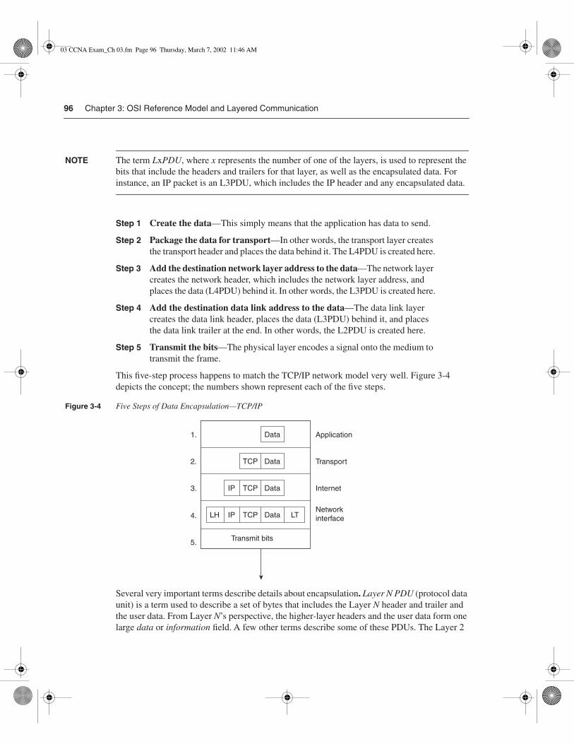
96 Chapter 3: OSI Reference Model and Layered Communication
NOTE The term LxPDU, where x represents the number of one of the layers, is used to represent the bits that include the headers and trailers for that layer, as well as the encapsulated data. For instance, an IP packet is an L3PDU, which includes the IP header and any encapsulated data.
Step 1 Create the data—This simply means that the application has data to send.
Step 2 Package the data for transport—In other words, the transport layer creates the transport header and places the data behind it. The L4PDU is created here.
Step 3 Add the destination network layer address to the data—The network layer creates the network header, which includes the network layer address, and places the data (L4PDU) behind it. In other words, the L3PDU is created here.
Step 4 Add the destination data link address to the data—The data link layer creates the data link header, places the data (L3PDU) behind it, and places the data link trailer at the end. In other words, the L2PDU is created here.
Step 5 Transmit the bits—The physical layer encodes a signal onto the medium to transmit the frame.
This five-step process happens to match the TCP/IP network model very well. Figure 3-4 depicts the concept; the numbers shown represent each of the five steps.
Figure 3-4 Five Steps of Data Encapsulation—TCP/IP
Several very important terms describe details about encapsulation. Layer N PDU (protocol data unit) is a term used to describe a set of bytes that includes the Layer N header and trailer and the user data. From Layer N’s perspective, the higher-layer headers and the user data form one large data or information field. A few other terms describe some of these PDUs. The Layer 2
LH IP TCP Data LT
IP TCP Data
TCP Data
Data Application
Transport
Internet
Networkinterface
1.
2.
3.
4.
5. Transmit bits
03 CCNA Exam_Ch 03.fm Page 96 Thursday, March 7, 2002 11:46 AM

OSI: Concepts, Layers, and Encapsulation 97
PDU (including the data link header and trailer) is called a frame. Similarly, the Layer 3 PDU is called a packet, or sometimes a datagram. Finally, the Layer 4 PDU is called a segment. Figure 3-5 illustrates the construction of frames, packets, and segments and the different layers’ perspectives on what is considered to be data.
Figure 3-5 Frames, Packets, and Segments
The TCP/IP and NetWare ProtocolsTwo of the most pervasively deployed protocols are TCP/IP and Novell NetWare; these also are the two key protocol architectures covered on the CCNA exam. TCP/IP and NetWare are covered in much more detail in the upcoming chapters.
This short section compares TCP/IP, Novell, and OSI. The goal is to provide some insight into what some popularly used terminology really means. In particular, routing is defined as a Layer 3 process; this section reviews how that term relates to TCP/IP and NetWare.
For perspective, Figure 3-6 shows the layers of these two protocols as compared with OSI.
Figure 3-6 OSI, TCP/IP, and NetWare Protocols
As Figure 3-6 illustrates, the IP and IPX protocols most closely match the OSI network layer—Layer 3. Many times, even on the CCNA exam, IP and IPX will be called Layer 3 protocols. Clearly, IP is in TCP/IP’s Layer 2, but for consistent use of terminology, it is commonly called a
TCP Data
IP Data
LH Data LTFrame
(L2 PDU)
Packet
(L3 PDU)
Segment
(L4 PDU)
Application
OSI
Presentation
Session
Transport
Network
Data link
Physical
TCP/IP
Application
TCP UDP
IP, ARP, ICMP
Network
interface
NetWare
SAP, NCP
SPX
IPX
MAC
protocols
03 CCNA Exam_Ch 03.fm Page 97 Thursday, March 7, 2002 11:46 AM

98 Chapter 3: OSI Reference Model and Layered Communication
Layer 3 protocol because its functions most closely match OSI’s Layer 3. Both IP and IPX define logical addressing, routing, the learning of routing information, and end-to-end delivery rules.
As with OSI Layers 1 and 2 (physical and data link, respectively), the lower layers of each stack simply refer to other well-known specifications. For example, the lower layers all support the IEEE standards for Ethernet and Token Ring, the ANSI standard for FDDI, the ITU standard for ISDN, and the Frame Relay protocols specified by the Frame Relay Forum, ANSI, and the ITU. The protocol stacks can accommodate other evolving Layer 1 and Layer 2 specifications more easily by referring to emerging international standards rather than trying to evolve these standards themselves.
OSI Transport Layer Functions
1 Describe connection-oriented network service and connectionless network service, and identify their key differences.
The transport layer (Layer 4) defines several functions, the most important of which are error recovery and flow control. Routers discard packets for many reasons, including bit errors, congestion that has caused a lack of buffer space, and instances in which no correct routes are known. The transport layer may provide for retransmission (error recovery) and can help avoid congestion (flow control), or it might not. When you compare similar protocols, you typically want to know whether they perform error recovery or flow control.
Connection-Oriented Versus Connectionless ProtocolsThe terms connection-oriented and connectionless have some relatively well-known connotations inside the world of networking protocols. The meaniing of the terms is intertwined with error recovery and flow control, but they are not the same. So, first, some basic definitions are in order:
Connection-oriented protocol—A protocol either that requires an exchange of mes-sages before data transfer begins or that has a required pre-established correlation between two endpoints
Connectionless protocol—A protocol that does not require an exchange of messages and that does not require a pre-established correlation between two endpoints
The definitions are sufficiently general so that all cases can be covered. TCP is connection-oriented because a set of three messages must be completed before data is exchanged. Likewise, SPX is connection-oriented. When using PVCs, Frame Relay does not require any
03 CCNA Exam_Ch 03.fm Page 98 Thursday, March 7, 2002 11:46 AM

OSI Transport Layer Functions 99
messages be sent ahead of time, but it does require predefinition in the Frame Relay switches, establishing a connection between two Frame Relay–attached devices. ATM PVCs are also connection-oriented, for similar reasons.
NOTE Some documentation refers to the terms connected or connection-oriented. These terms are used synonymously. You will most likely see the use of the term connection-oriented in Cisco documentation.
Many people confuse the real meaning of connection-oriented with the definition of a reliable, or error-recovering, protocol. A great example that you will learn more about in this book is Frame Relay. Frame Relay requires that some connection be established before any data can flow between two endpoints. However, there is no error receovery. Table 3-4 lists some popular protocols and tells whether they are connected or reliable.
Error RecoveryCisco expects CCNAs to be able to distinguish between error detection and error recovery. Any header or trailer with a frame check sequence (FCS) or similar field can be used to detect bit errors in the PDU. The FCS uses some magic math against the contents of the frame, with the result recorded in the FCS field. If the receiving device repeats the same math but gets a different value than what is in the FCS field, there were bit errors in transmission. Error detection uses the FCS to detect the error, which results in discarding the PDU. However, error recovery implies that the protocol reacts to the lost data and somehow causes the data to be retransmitted.
Many protocols offer error recovery, and these protocols accomplish the task in the same general way. Generically, the transmitted data is labeled or numbered. After receipt, the receiver signals back to the sender that the data was received, using the same label or number to identify the data. Figure 3-7 summarizes the operation.
Table 3-4 Protocol Characteristics: Recovery and Connections
Connected? Reliable? Examples
Connection-oriented Yes LLC Type 2 (802.2), TCP (TCP/IP), SPX (NetWare), X.25
Connection-oriented No Frame Relay virtual circuits, ATM virtual connections, PPP
Connectionless Yes TFTP, NetWare NCP (without Packet Burst)
Connectionless No UDP, IP, IPX, AppleTalk DDP, most Layer 3 protocols, 802.3, 802.5
03 CCNA Exam_Ch 03.fm Page 99 Thursday, March 7, 2002 11:46 AM

100 Chapter 3: OSI Reference Model and Layered Communication
Figure 3-7 Forward Acknowledgement
As Figure 3-7 illustrates, the data is numbered, as shown with the numbers 1, 2, and 3. These numbers are placed into the header used by that particular protocol; for example, the TCP header contains similar numbering fields. When Barney sends his next segment to Fred, Barney acknowledges that all three segments were received by setting his acknowledgment field to 4. The number 4 refers to the next data to be received, which is called forward acknowledgment. This means that the acknowledgment number in the header identifies the next data that is to be received, not the last one received. (In this case, 4 is next to be received.)
In some protocols, such as LLC2, the numbering always starts with zero. In other protocols, such as TCP, the number is stated during initialization by the sending machine. Also, some protocols count the frame/packet/segment as 1; others count the number of bytes sent. In any case, the basic idea is the same.
Of course, error recovery has not been covered yet. Take the case of Fred and Barney again, but notice Barney’s reply in Figure 3-8.
Sending #1
Sending #2
Sending #3
Barney wants #4 nextso he must have�received #1-#3
Receiving #1
Receiving #2
Receiving #3
I acknowledge, sendme 4
Network
Fred Barney
Passes FCS
Passes FCS
Passes FCS
03 CCNA Exam_Ch 03.fm Page 100 Thursday, March 7, 2002 11:46 AM

OSI Transport Layer Functions 101
Figure 3-8 Recovery Example
What should Fred do next? Well, Fred certainly should resend number 2. However, should Fred resend number 3? Two choices exist. Fred could send numbers 2 and 3 again, or Fred could send number 2 and wait, hoping that Barney’s next acknowledgment will say 4, indicating that Barney just got number 2 and already had number 3 from earlier. What happens in real life is dependant on the praticular protocol.
Finally, error recovery typically uses two sets of counters: one to count data in one direction, and one to count data in the opposite direction. So, the numbers 1, 2, and 3 in the segments sent by Fred would be in the Number Sent field of some header. Barney acknowledges packet number 2 with the Number Acknowledged field in the header. Similarly, segments sent by Barney also have a Number Sent field that identifies the data in Barney’s packet, and the Number Acknowledged field in Fred’s segments would be used to acknowledge segments sent by Barney.
Table 3-5 summarizes the concepts behind error recovery and lists the behavior of three popular error-recovery protocols.
Sending #1
Sending #2
Sending #3
He acknowledgedjust 1!
Receiving #1
Receiving #2
Receiving #3
I acknowledge, sendme #2
Network
Fred Barney
Passes FCS
Fails FCS
Passes FCS
03 CCNA Exam_Ch 03.fm Page 101 Thursday, March 7, 2002 11:46 AM

102 Chapter 3: OSI Reference Model and Layered Communication
Flow ControlFlow control is the process of controlling the rate at which a computer sends data. Depending on the particular protocol, both the sender and the receiver of the data (as well as any intermediate routers, bridges, or switches) might participate in the process of controlling the flow from sender to receiver.
Flow control prevents unnecessary congestion by attempting to send data at a rate that the network can currently accomodate. A sender of data might be sending the data faster than the receiver can receive the data, so the receiver discards the data. Also, the sender might be sending the data faster than the intermediate switching devices (switches and routers) can forward the data, also causing discards. Packets can be lost because of transmission errors as well. This happens in every network, sometimes temporarily and sometimes regularly, depending on the network and the traffic patterns. The receiving computer can have insufficient buffer space to receive the next incoming frame, or possibly the CPU is too busy to process the incoming frame. Intermediate routers might need to discard the packets based on temporary lack of buffers or processing as well.
Flow control attempts to reduce unnecessary discarding of data. Comparing flows when flow control is used and when it is not used is helpful for understanding why flow control can be useful. Without flow control, some PDUs are discarded. If some reliable protocol in use happens to implement error recovery, the data is resent. The sender keeps sending as fast as possible. With flow control, the sender can be slowed enough that the original PDU can be forwarded to the receiving computer, and the receiving computer can process the PDU. Flow-control protocols do not prevent the loss of data as a result of congestion; these protocols simply reduce the amount of lost data, which, in turn, reduces the amount of retransmitted traffic, which hopefully reduces overall congestion. However, with flow control, the sender is artificially slowed or throttled so that it sends data less quickly than it could without flow control.
Table 3-5 Examples of Error-Recovery Protocols and Their Features
Feature TCP SPX LLC2
Acknowledges data in both directions? Yes Yes Yes
Uses forward acknowledgment? Yes Yes Yes
Counts bytes or frame/packets? Bytes Packets Frames
Necessitates resending of all data, or just one part and wait when resending?
One and wait Resend all Resend all
03 CCNA Exam_Ch 03.fm Page 102 Thursday, March 7, 2002 11:46 AM

OSI Transport Layer Functions 103
The CCNA exam requires that you be familiar with three features, or methods, of implementing flow control:
• Buffering
• Congestion avoidance
• Windowing
BufferingBuffering simply means that the computers reserve enough buffer space that bursts of incoming data can be held until processed. No attempt is made to actually slow the transmission rate of the sender of the data. In fact, buffering is such a common method of dealing with changes in the rate of arrival of data that most of us probably would just assume that it is happening. However, some older documentation refers to “three methods of flow control,” of which buffering is one of the methods, so be sure to remember it as a separate function.
Congestion AvoidanceCongestion avoidance is the second method of flow control covered here. The computer receiving the data notices that its buffers are filling. This causes either a separate PDU or a field in a header to be sent toward the sender, signaling the sender to stop transmitting. Figure 3-9 shows an example.
Figure 3-9 Congestion-Avoidance Flow Control
Sender Receiver
1
2
3
4
5
6
Stop
Go
.....
I'm overwhelmed! I'lltell him to stop!
I've caught up. I'll tellhim to send again.
03 CCNA Exam_Ch 03.fm Page 103 Thursday, March 7, 2002 11:46 AM
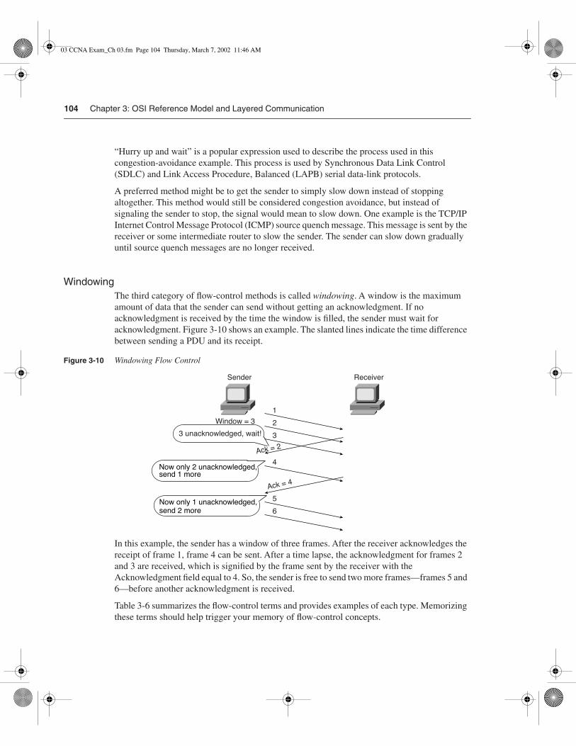
104 Chapter 3: OSI Reference Model and Layered Communication
“Hurry up and wait” is a popular expression used to describe the process used in this congestion-avoidance example. This process is used by Synchronous Data Link Control (SDLC) and Link Access Procedure, Balanced (LAPB) serial data-link protocols.
A preferred method might be to get the sender to simply slow down instead of stopping altogether. This method would still be considered congestion avoidance, but instead of signaling the sender to stop, the signal would mean to slow down. One example is the TCP/IP Internet Control Message Protocol (ICMP) source quench message. This message is sent by the receiver or some intermediate router to slow the sender. The sender can slow down gradually until source quench messages are no longer received.
WindowingThe third category of flow-control methods is called windowing. A window is the maximum amount of data that the sender can send without getting an acknowledgment. If no acknowledgment is received by the time the window is filled, the sender must wait for acknowledgment. Figure 3-10 shows an example. The slanted lines indicate the time difference between sending a PDU and its receipt.
Figure 3-10 Windowing Flow Control
In this example, the sender has a window of three frames. After the receiver acknowledges the receipt of frame 1, frame 4 can be sent. After a time lapse, the acknowledgment for frames 2 and 3 are received, which is signified by the frame sent by the receiver with the Acknowledgment field equal to 4. So, the sender is free to send two more frames—frames 5 and 6—before another acknowledgment is received.
Table 3-6 summarizes the flow-control terms and provides examples of each type. Memorizing these terms should help trigger your memory of flow-control concepts.
Sender
Window = 3
Receiver
1
2
5
6
3
4
Ack =4
Ack =2
3 unacknowledged, wait!
Now only 2 unacknowledged,send 1 more
Now only 1 unacknowledged,send 2 more
03 CCNA Exam_Ch 03.fm Page 104 Thursday, March 7, 2002 11:46 AM

OSI Data Link Layer Functions 105
OSI Data Link Layer Functions
5 Describe data-link and network addresses, and identify key differences between them.
6 Define and describe the function of a MAC address.
As a CCNA, you’ll need to understand both the abstract concepts about the OSI layers and particular instances of such protocols. This section focuses on more of the abstract concepts. Later chapters provide more details about particular LAN and WAN data-link protocols, as well as their configuration in the IOS.
This section examines four different protocols: Ethernet, Token Ring, HDLC, and Frame Relay. A generalized definition of the function of a data-link protocol will be used to guide you through the comparison of these four data-link protocols. This definition could be used to examine any other data-link protocol. The four components of this definition of the functions of data-link (Layer 2) protocols are as follows:
• Arbitration—Determines when it is appropriate to use the physical medium.
• Addressing—Ensures that the correct recipient(s) receives and processes the data thatis sent.
• Error detection—Determines whether the data made the trip across the medium successfully.
• Identifying the encapsulated data—Determines the type of header that follows the data-link header. This feature is included in a subset of data-link protocols.
Engineers deploy Ethernet as the chosen type of LAN, but, for the sake of comparison, Token Ring concepts are covered here briefly. These protocols are defined by the IEEE in specifications 802.3 and 802.5, respectively. Because 802.3 and 802.5 define how a station accesses the media, the IEEE calls these protocols Media Access Control (MAC) protocols.
Table 3-6 Flow-Control Methods—Summary
Name Used in This Book Other Names Example Protocols
Buffering N/A N/A
Congestion avoidance Stop/start, RNR, source quench SDLC, LAPB, LLC2
Windowing N/A TCP, SPX, LLC2
03 CCNA Exam_Ch 03.fm Page 105 Thursday, March 7, 2002 11:46 AM

106 Chapter 3: OSI Reference Model and Layered Communication
Also, both 802.3 and 802.5 call for the use of another IEEE specification as a separate part of the data link layer—namely, 802.2 Logical Link Control (LLC). 802.2 purposefully is designed to provide functions common to both Ethernet and Token Ring, whereas 802.3 and 802.5 were designed specifically for data-link functions pertinent to either Ethernet or Token Ring topologies, respectively.
The IEEE created 802.3 and 802.2 after the original creation of Ethernet. The original specification is called DIX Ethernet, with the letters DIX representing Digital, Intel, and Xerox, giving credit to the creators. DIX Version 2 (the latest and final DIX specification) defines similar functions to both the 802.3 and 802.2 specifications.
HDLC is the default data-link protocol (encapsulation) on Cisco routers’ serial interfaces. Frame Relay headers coincidentally are based on the HDLC specification, but Frame Relay was created for multiaccess networks (with more than two devices). The clear differences between Frame Relay and HDLC provide a good backdrop to examine the functions of the data link layer (Layer 2).
Data Link Function 1: ArbitrationArbitration is needed only when there are instants in time during which it is not appropriate to send data across the media. It’s like trying to get through an intersection in your car when all the traffic signals are out—you all want to use the intersection, but you had better use it one at a time! The arbitration methods vary greatly, depending on how conserative you are, how big the other cars are, how new or old your car is, and how much you value your own life! LANs originally were defined as a shared medium on which each device must wait until the appropriate time to send data. The specifications for these data-link protocols define how to arbitrate the use of the physical medium.
Ethernet uses the carrier sense multiple access collision detect (CSMA/CD) algorithm for arbitration. The basic algorithm for using an Ethernet when there is data to be sent consists of the following steps:
1 Listen to find out whether a frame is currently being received.
2 If no other frame is on the Ethernet, send.
3 If another frame is on the Ethernet, wait and then listen again.
4 While sending, if a collision occurs, stop, wait, and listen again.
With Token Ring, a totally different mechanism is used. A free-token frame rotates around the ring while no device has data to send. When sending, a device claims the free token, which really means changing bits in the 802.5 header to signify “token busy.” The data then is placed onto the ring after the Token Ring header. The basic algorithm for using a Token Ring when there is data to be sent consists of the following steps:
1 Listen for the passing token.
2 If token is busy, listen for the next token.
03 CCNA Exam_Ch 03.fm Page 106 Thursday, March 7, 2002 11:46 AM

OSI Data Link Layer Functions 107
3 If the token is free, mark the token as a busy token, append the data, and send the data onto the ring.
4 When the header with the busy token returns to the sender of that frame, after completing a full revolution around the ring, the sender removes the data from the ring.
5 The same device that just sent the frame sends a free token to allow another station to send a frame.
The algorithm for Token Ring does have other rules and variations, but these are beyond the depth of what is needed for the CCNA exam. Network Associates (the “Sniffer” people) have an excellent class covering Token Ring in detail. To find out more about these classes, goto www.nai.com.
With HDLC, arbitration is a nonissue today. HDLC is used on point-to-point links, which are typically full-duplex (four-wire) circuits. In other words, either endpoint can send at any time on a full-duplex link. Full-duplex operation is analogous to driving down a two-lane road—cars pass you going the other direction with no problem because there is a lane for each direction.
From a physical perspective, Frame Relay is comprised of a leased line between a router and the Frame Relay switch. These links are also typically full-duplex links, so no arbitration is needed. The Frame Relay network is shared among many data terminal equipment (DTE) devices, whereas the access link is not shared, so arbitration of the medium is not an issue.
NOTE As used in this book and in the ICND course, the word frame refers to particular parts of the data as sent on a link. In particular, frame implies that the data-link header and trailer are part of the bits being examined and discussed. Figure 3-11 shows frames for the four data-link protocols.
Figure 3-11 Popular Frame Formats
Data Link Function 2: AddressingCisco requires that CCNAs master the formats and meanings of data link layer and network layer addresses. LANs need addressing because there can be many possible recipients of data—that is, there could be more than two devices on the link. LANs behave much like people when you have a meeting with three or more people: If you want to say something to someone in particular, you first say that person’s name—or at least look at him. Or, if you want to tell everyone in the meeting something, you just say it because they can all hear you. Likewise, LANs are broadcast media—a term signifying that all devices on the media receive the same data.
802.3 802.2 Data 802.3
802.5 802.2 Data 802.5
HDLC Data HDLC
F.R. Data F.R.
03 CCNA Exam_Ch 03.fm Page 107 Thursday, March 7, 2002 11:46 AM

108 Chapter 3: OSI Reference Model and Layered Communication
With Ethernet and Token Ring, the addresses are very similar. Each uses Media Access Control (MAC) addresses, which are 6 bytes long and are represented as a 12-digit hexadecimal number. Table 3-7 summarizes most of the details about MAC addresses.
HDLC includes a meaningless address field because it is used only on point-to-point serial links. The recipient is implied; if one device sent a frame, the other device is the only possible intended recipient. In the earlier analogy of three or more people in a meeting, point-to-point links are more like a meeting with two people—you do not have to say someone’s name before you speak because the other person is the only one you can talk to!
Frame Relay acts more like a LAN than a point-to-point link, regarding the need for addressing. With Frame Relay, there is one physical link that has many logical circuits called virtual circuits
Table 3-7 LAN MAC Address Terminology and Features
LAN Addressing Terms and Features Description
MAC Media Access Control. 802.3 (Ethernet) and 802.5 (Token Ring) are the MAC sublayers of these two LAN data-link protocols.
Ethernet address, NIC address, LAN address, Token Ring address, card address
Other names often used instead of MAC address. These terms describe the 6-byte address of the LAN interface card.
Burned-in address The 6-byte address assigned by the vendor making the card. It usually is burned into a ROM or EEPROM on the LAN card and begins with a 3-byte organizationally unique identifier (OUI) assigned by the IEEE.
Locally administered address Through configuration, an address that is used instead of the burned-in address.
Unicast address Fancy term for a MAC that represents a single LAN interface.
Broadcast address An address that means “all devices that reside on this LAN right now.”
Multicast address Not valid on Token Ring. On Ethernet, a multicast address implies some subset of all devices currently on the LAN.
Functional address Not valid on Ethernet. On Token Ring, these addresses are reserved to represent the device(s) on the ring performing a particular function. For example, all source-route bridges supply the ring number to other devices; to do so, they each listen for the Ring Parameter Server (RPS) functional address.
03 CCNA Exam_Ch 03.fm Page 108 Thursday, March 7, 2002 11:46 AM

OSI Data Link Layer Functions 109
(VCs). (See Chapter 10, “Frame Relay Concepts and Configuration,” for more background on Frame Relay.) The address field in Frame Relay defines a data-link connection identifier (DLCI), which identifies each VC. For example, in Figure 3-12, the Frame Relay switch to which router Timbuktu is connected receives frames; the switch forwards the frame to either Kalamazoo or East Egypt based on the DLCI, which identifies each VC. So, Timbuktu has one physical connection but multiple logical connections.
Figure 3-12 Frame Relay Network
Data Link Function 3: Error DetectionError detection discovers whether bit errors occurred during the transmission of the frame. To do this, most data links include a frame check sequence (FCS) or cyclical redundancy check (CRC) field in the data link trailer. This field contains a value that is the result of a mathematical formula applied to the data in the frame. The FCS value calculated and sent by the sender should match the value calculated by the receiver. All four data links discussed in this section contain an FCS field in the frame trailer.
Error detection does not imply recovery; most data links, including 802.5 Token Ring and 802.3 Ethernet, do not provide error recovery. In these two cases, however, an option in the 802.2 protocol, called LLC Type 2, does perform error recovery. (SNA and NetBIOS are the typical higher-layer protocols in use that request the services of LLC2.) Neither HDLC or Frame Relay does error recovery.
Data Link Function 4: Identifying the Encapsulated DataFinally, the fourth part of a data link identifies the contents of the data field in the frame. Figure 3-13 helps make the usefulness of this feature apparent.
Kalamazoo
East Egypt
PacketTimbuktu
What do I do? Lookat the address!
03 CCNA Exam_Ch 03.fm Page 109 Thursday, March 7, 2002 11:46 AM

110 Chapter 3: OSI Reference Model and Layered Communication
Figure 3-13 Multiplexing Using Data Link Type and Protocol Fields
When PC1 receives data, does it give the data to the TCP/IP software or the NetWare client software? Of course, that depends on what is inside the data field. If the data came from the Novell server, PC1 hands the data off to the NetWare client code. If the data comes from the Sun FTP server, PC1 hands it off to the TCP/IP code. But what does PC1 look at to make this decision? Well, Ethernet and Token Ring 802.2 LLC use a field in its header to identify the type of data in the data field, and that is the field that PC1 examines to decide whether the packet is an IP packet or an IPX packet.
Each data-link header has a field with a code that means IP, IPX, or some other designation defining the type of protocol header that follows. For example, in the first frame in Figure 3-14, the destination service access point (DSAP) field has a value of E0, which means that the next header is a Novell IPX header. Why is that? Well, when the IEEE created 802.2, they saw the need for a protocol type field. They called it DSAP, and anyone could register favorite protocols to use a reserved value in the DSAP field; Novell registered IPX and was assigned hex E0 by the IEEE.
However, the IEEE did not plan for a large number of protocols—in fact, the 1-byte-long DSAP field is not big enough to number them all. In the second frame of Figure 3-14, the DSAP field is AA, which implies that a subnetwork access protocol (SNAP) header follows. The SNAP header uses a 2-byte protocol type field, which has a value of 0800 in this case, signifying that the next header is an IP header. RFC 1700, the “Assigned Numbers” RFC (http://www.isi.edu/in-notes/rfc1700.txt), lists the SAP and SNAP Type field values and the protocol types that they imply.
Data link
PC1
NetWareclient
FTPclient
Novellserver
SunFTP
server
802.3 802.2 Data 802.3 802.3 802.2 Data 802.3
03 CCNA Exam_Ch 03.fm Page 110 Thursday, March 7, 2002 11:46 AM

OSI Data Link Layer Functions 111
Figure 3-14 802.2 SAP and SNAP Type Fields
Similarly, HDLC and Frame Relay need to identify the contents of the data field. Of course, it is atypical to have end-user devices attached to either of these types of data links. In this case, routers provide an example more typically found in most WAN environments, as shownin Figure 3-15.
Figure 3-15 Identifying Protocols over HDLC and Frame Relay
802.303
CTLOUI
802.2 SNAP
IP data 802.3AA
DSAP
AA
SSAP
0800
Type
802.3
14
14
1
1
1
1
1 4
1 3 2 4
CTL IPX data 802.3E0
DSAP
E0
SSAP
R1
Barney
Fred
(NetWare
server)
Sun
FTP
server
R2
Frame Relay
R1
Barney
Fred
(NetWare
server)
Sun
FTP
server
R2Point-to-Point
HDLC Data HDLC
Frame
RelayData
Frame
Relay
Do I look in
the IP or IPX
routing table?
Do I look in
the IP or IPX
routing table?
03 CCNA Exam_Ch 03.fm Page 111 Thursday, March 7, 2002 11:46 AM

112 Chapter 3: OSI Reference Model and Layered Communication
Referring to the top part of Figure 3-15, if Barney is using FTP to transfer files to the Sun system and also is connected to the NetWare server (Fred) using IPX, Barney will generate both TCP/IP and NetWare IPX traffic. As this traffic passes over the HDLC-controlled link, R2 will need to know whether an IP or IPX packet follows the HDLC header. Mainly, this is so that the router can find the Layer 3 destination address, assume its length (32 bits or 80 bits), perform table lookup in the correct routing table (IP or IPX), and make the correct routing decision.
HDLC does not provide a mechanism to identify the type of packet in the data field. IOS adds a proprietary 2-byte field immediately after the HDLC header that identifies the contents of the data. Likewise, with Frame Relay, the receiving router (R2) needs to know whether an IP or IPX packet follows the Frame Relay header. Frame Relay headers originally did not address this issue, either, because the headers were based on HDLC. However, the IETF created a specification called RFC 1490 that defined additional headers that followed the standard Frame Relay header. These headers include several fields that can be used to identify the data so that the receiving device knows what type is hidden inside.
The ITU and ANSI picked up the specifications of RFC 1490 and added it to their official Frame Relay standards: ITU T1.617 Annex F and ANSI Q.933 Annex E, respectively.
Figure 3-16 shows the fields that identify the type of protocol found in the data field.
Figure 3-16 Identifying Protocols over HDLC and Frame Relay
As Figure 3-16 shows, a Protocol Type field comes after the HDLC Control field. In the Frame Relay example, four different options exist for identifying the type of data inside the frame. RFC 2427, which obsoletes RFC 1490, provides a complete reference and is useful reading for those of you moving on to CCNP certification (see www.isi.edu/in-notes/rfc2427.txt). (“Obsoletes” in the RFC world implies that a newer document has superceded it but does not necessarily mean that all or most of the original RFC has been changed.)
Table 3-8 summarizes the different choices for encoding protocol types for each of the four data-link protocols. Notice that the length of some of these fields is only 1 byte, which historically has led to the addition of other headers that have a 2-byte Protocol Type field
Flag Data FCSAddress Control Protocoltype *
HDLC
Flag Data FCSAddress Control Pad
Optional Optional
NLPID SNAPL2PID
Frame Relay
L3PID
1 2 3 4
* Cisco proprietary
One option for protocol type Four options for protocol type
03 CCNA Exam_Ch 03.fm Page 112 Thursday, March 7, 2002 11:46 AM
OSI Data Link Layer Functions 113
because 1 byte is just not enough to number all the different protocols. For example, the SNAP header contains a 2-byte type field because a 1-byte DSAP field is not big enough to number all the available options for what type of protocol is inside the data.
Summary: Data Link FunctionsTable 3-9 summarizes the basic functions of data-link protocols.
Table 3-8 Different Choices for Encoding Protocol Types for Each of the Four Example Data-Link Protocols
Data-Link Protocol FieldHeader in Which It Is Found Size
802.3 Ethernet and 802.5 Token Ring
DSAP 802.2 header 1 byte
802.3 Ethernet and 802.5 Token Ring
SSAP 802.2 header 1 byte
802.3 Ethernet and 802.5 Token Ring
Protocol Type SNAP header 2 bytes
Ethernet (DIX) Ethertype Ethernet header 2 bytes
HDLC Cisco-proprietary Protocol ID field
Extra Cisco header 2 bytes
Frame Relay RFC 2427 NLPID RFC 1490 1 byte
Frame Relay RFC 2427 L2 or L3 Protocol ID Q.933 2 bytes each
Frame Relay RFC 2427 SNAP Protocol Type SNAP Header 2 bytes
Table 3-9 Data-Link Protocol Functions
Function Ethernet Token Ring HDLC Frame Relay
Arbitration CSMA/CD algorithm (partof MAC)
Token passing (part of MAC)
N/A N/A
Addressing Source and destination MAC addresses
Source and destination MAC addresses
Single 1-byte address; unimportant on point-to-point links
DLCI used to identify virtual circuits
Error detection
FCS in trailer FCS in trailer FCS in trailer FCS in trailer
continues
03 CCNA Exam_Ch 03.fm Page 113 Thursday, March 7, 2002 11:46 AM

114 Chapter 3: OSI Reference Model and Layered Communication
OSI Network Layer Functions
9 Identify the parts in specific protocol address examples.
12 Describe the two parts of network addressing, and then identify the parts in specific protocol address examples.
OSI Layer 3 equivalent protocols use routing and addressing to accomplish their goals. The choices made by the people who made up addressing greatly affect how routing works, so the two topics are best described together.
Network layer (Layer 3) addressing will be covered in enough depth to describe IP, IPX, and AppleTalk addresses. Also, now that data link layer and network layer addresses have been covered in this chapter, this section undertakes a comparison between the two.
RoutingRouting can be thought of as a three-step process, as seen in Figure 3-17. Thinking about routing in these three separate steps helps make some of the details more obvious. However, most people will not think of routing as a three-step process when going about their normal jobs—this is just a tool to make a few points more clearly.
As illustrated in Figure 3-17, the three steps of routing include the following:
Step 1 Sending the data from the source computer to some nearby router
Step 2 Delivering the data from the router near the source to a router near the destination
Step 3 Delivering the data from the router near the destination to the end destination computer
Function Ethernet Token Ring HDLC Frame Relay
Identifying contents of data
802.2 DSAP, SNAP header, or Ethertype, as needed
802.2 DSAP or SNAP header, as needed
Proprietary Type field
RFC 1490/2427 headers, with NLPID, L2 and L3 protocol IDs, or SNAP header
Table 3-9 Data-Link Protocol Functions (Continued)
03 CCNA Exam_Ch 03.fm Page 114 Thursday, March 7, 2002 11:46 AM

OSI Network Layer Functions 115
Figure 3-17 Three Steps of Routing
Sending Data to a Nearby RouterThe creator of the data, who is also the sender of the data, decides to send data to a device in another group. A mechanism must be in place so that the sender knows of some router on a common data link with the sender to ensure that data can be sent to that router. The sender sends a data-link frame across the medium to the nearby router; this frame includes the packet in the data portion of the frame. That frame uses data link layer (Layer 2) addressing in the data-link header to ensure that the nearby router receives the frame. The main point here is that the originator of the data does not know much about the network—just how to get the data to some nearby router. In the post office analogy, I know how to get to the local post office, but that’s all I need to know to send that letter to Mike in Califonia.
Routing Data Across the NetworkThe routing table for that particular network layer protocol contains a list of network layer address groupings. Instead of a single entry in the routing table per destination address, there is one entry per group. The router compares the destination network layer address in the packet to the entries in the routing table in memory, and a match is made. This matching entry in the routing table tells this router where to forward the packet next.
The concept of network layer address grouping is identical to the U.S. ZIP code system. Everyone living in the same vicinity is in the same ZIP code, and the postal sorters just look for the ZIP codes, ignoring the rest of the address.
Any intervening routers repeat the same process. The destination network layer (Layer 3) address in the packet identifies the group in which the destination resides. The routing table is searched for a matching entry, which tells this router where to forward the packet next. Eventually, the packet is delivered to the router connected to the network or subnet of the destination host, as previously shown in Figure 3-17.
Bunches
of
routers
R1 R2Fred Barney
Step 2
Step 1 Step 3
03 CCNA Exam_Ch 03.fm Page 115 Thursday, March 7, 2002 11:46 AM

116 Chapter 3: OSI Reference Model and Layered Communication
Delivering Data to the End DestinationThe final router in the path also needs a list of all the address groupings, but because the destination is on the same LAN as the router, this final router needs to look at the entire address. When the packet arrives at a router sharing a data link with the true destination, the router and the destination of the packet are in the same L3 grouping. That final router can forward the data directly to the destination. As usual, a new data-link header and trailer are created before a frame (which contains the packet that made the trip across the entire network) can be sent on to the media. This matches the final step (Step 3), as previously shown in Figure 3-17.
A Comment About Data LinksBecause the routers build new data-link headers and trailers, and because the new headers contain data-link addresses, the routers must have some way to decide what data-link addresses to use. An example of how the router determines which data-link address to use is the IP Address Resolution Protocol (ARP) protocol. ARP is used to dynamically learn the data-link address of some IP host.
An example specific to TCP/IP will be useful to solidify the concepts behind routing. Imagine that PC1 is sending packets to PC2. (If you do not understand the basics of IP addressing already, you might want to bookmark this page and refer to it after you have reviewed Chapter 5, which covers IP addressing.) Figure 3-18 provides an example network so that you can review the routing process.
Figure 3-18 Routing Logic and Encapsulation—PC1 Sending to PC2
FR
PC1
PC2
R1
R2
R3
10.0.0.0
10.1.1.1
168.1.1.1
168.10.0.0
168.11.0.0
168.1.0.0
My route
to that group is
out seriallink.
Send directly
to Barney.
My route
to that group is
out Frame
Relay.
Destination is in
another group; send
to nearby router.
Eth. IP packet
HDLC IP packet
FR IP packet
TR IP packet
Steps A, B
Steps C, D, E
Steps F, G
Step H
03 CCNA Exam_Ch 03.fm Page 116 Thursday, March 7, 2002 11:46 AM

OSI Network Layer Functions 117
The logic behind the earlier three-step routing process is described in the following more detailed steps:
Step A PC1 needs to know its nearby router. PC1 first knows of R1’s IP address by having either a default router or a default gateway configured. The default router defined on some host is the router to which that host forwards packets that are destined for subnets other than the directly attached subnet. Assume that a default router of 10.1.1.100 is configured on PC1 and that it is R1’s Ethernet IP address.
Step B PC1 needs to know R1’s Ethernet MAC address before PC1 can finish building the Ethernet header (see Figure 3-18). In the case of TCP/IP, the ARP process is used to dynamically learn R1’s MAC address. (See Chapter 5 for a discussion of ARP.) When R1’s MAC address is known, PC1 completes the Ethernet header with the destination MAC address being R1’s MAC address and sends the packet to R1.
Step C At Step 2 of the routing process, the router has many items to consider. First, the incoming frame (Ethernet interface) is processed only if the Ethernet FCS is passed and the router’s MAC address is in the destination address field. Then the appropriate Protocol Type field is examined so that R1 knows what type of packet is in the data portion of the frame. At this point, R1 discards the Ethernet header and trailer.
Step D The next part of Step 2 involves finding an entry in the routing table for network 168.1.0.0, the network of which PC2 is a member. In this case, the route in R1 references 168.1.0.0 and lists R1’s serial interface as the interface by which to forward the packet.
Step E To complete Step 2, R1 builds an HDLC header and trailer to place around the IP packet. Because the HDLC data link uses the same address field every time, no process such as ARP is needed to allow R1 to build the HDLC header.
Step F Routing Step 2 is repeated by R2 when it receives the HDLC frame. The HDLC FCS is checked; the type field is examined to learn that the packet inside the frame is an IP packet, and then the HDLC header and trailer are discarded. The IP routing table in R2 is examined for network 168.1.0.0, and a match is made. The entry directs R2 to forward the packet to its Frame Relay serial interface. The routing entry also identifies the next router’s IP address—namely, R3’s IP address on the other end of the Frame Relay VC.
03 CCNA Exam_Ch 03.fm Page 117 Thursday, March 7, 2002 11:46 AM
118 Chapter 3: OSI Reference Model and Layered Communication
Step G Before R2 can complete its Step 2 of this end-to-end routing algorithm, R2 must build a Frame Relay header and trailer. Before it can complete the task, the correct DLCI for the VC to R3 must be decided. In most cases today, the dynamic Inverse ARP process will have associated R3’s IP address with the DLCI that R2 uses to send frames to R3. (See Chapter 8 for more details on Inverse ARP and Frame Relay mapping.) With that mapping information, R2 can complete the Frame Relay header and send the frame to R3.
Step H Step 3 of the original algorithm is performed by R3. Like R1 and R2 before it, R3 checks the FCS in the data link trailer, looks at the type field to decide whether the packet inside the frame is an IP packet, and then discards the Frame Relay header and trailer. The routing table entry for 168.1.0.0 shows that the outgoing interface is R3’s Token Ring interface. However, there is no next-router IP address because there is no need to forward the packet to another router. R3 simply needs to build a Token Ring header and trailer and forward the frame that contains the original packet to PC2. Before R3 can finish building the Token Ring header, an IP ARP must be used to find PC2’s MAC address (assuming that R3 doesn’t already have that information in its IP ARP cache).
Network Layer (Layer 3) AddressingCisco requires that CCNAs master the details of Layer 3 addressing, both the concepts and the particulars of IP and IPX. One key feature of network layer addresses is that they were designed to allow logical grouping of addresses. In other words, something about the numeric value of an address implies a group or set of addresses, all of which are considered to be in the same grouping. In TCP/IP, this group is called a network or a subnet. In IPX, it is called a network. In AppleTalk, the grouping is called a cable range. These groupings work just like USPS ZIP codes, allowing the routers (mail sorters) to speedily route (sort) lots of packets (letters).
Just like street addresses, network layer addresses are grouped based on physical location in a network. The rules differ for some network layer protocols, but the grouping concept is identical for IP, IPX, and AppleTalk. In each of these network layer protocols, all devices with addresses in the same group cannot be separated from each other by a router that is configured to route that protocol, respectively. Stated differently, all devices in the same group (IP subnet/IPX network/AppleTalk cable range) must be connected to the same data link; for example, all devices must be connected to the same Ethernet to be in the same group.
03 CCNA Exam_Ch 03.fm Page 118 Thursday, March 7, 2002 11:46 AM
OSI Network Layer Functions 119
Routing relies on the fact that Layer 3 addresses are grouped together. The routing tables for each network layer protocol can have one entry for the group, not one entry for each individual address. Imagine an Ethernet with 100 Novell clients. A router needing to forward packets to any of those clients needs only one entry in its IPX routing table. If those clients in the same IPX network were not required to be attached to the same data link, and if there was no way to encode the IPX network number as part of the IPX address of the client, routing would not be capable of using just one entry in the table. This basic fact is one of the key reasons that routers can scale to allow tens and hundreds of thousands of devices. It’s very similar to the USPS ZIP code system—it would be ridiculous to have people in the same ZIP code as me live somewhere far away. Likewise, devices in the same IP subnet, IPX network, or AppleTalk cable range are physically close, relatively speaking.
With that in mind, most network layer (Layer 3) addressing schemes were created with the following goals:
• The address space should be large enough to accommodate the largest network for which the designers imagined the protocol would be used.
• The addresses should allow for unique assignment so that little or no chance of address duplication exists.
• The address structure should have some grouping implied so that many addresses are considered to be in the same group.
• Dynamic address assignment for clients is desired.
A great analogy for this concept of network addressing is the addressing scheme used by the U.S. Postal Service. Instead of getting involved with every small community’s plans for what to name new streets, the post office simply has a nearby office with a ZIP code. The rest of the post offices in the country are already prepared to send mail to new businesses and residences on the new streets because they care only about the ZIP code, which they already know. It is the local postmaster’s job to assign a mail carrier to deliver and pick up mail on those new streets. There might be hundreds of Main streets in different ZIP codes, but as long as there is just one per ZIP code, the address is unique—and with an amazing percentage of success, the U.S. Postal Service delivers the mail to the correct address.
Example Layer 3 Address StructuresEach Layer 3 address structure contains at least two parts. One (or more) part at the beginning of the address works like the ZIP code and essentially identifies the grouping. All instances of addresses with the same value in these first bits of the address are considered to be in the same group—for example, the same IP subnet or IPX network or AppleTalk cable range. The last part of the address acts as a local address, uniquely identifying that device in that particular group. Table 3-10 outlines several Layer 3 address structures.
03 CCNA Exam_Ch 03.fm Page 119 Thursday, March 7, 2002 11:46 AM

120 Chapter 3: OSI Reference Model and Layered Communication
Routing ProtocolsConveniently, the routing tables in the example based on Figure 3-18 had the correct routing information already in their routing tables. In most cases, these entries are built dynamically by use of a routing protocol. Routing protocols define message formats and procedures, just like any other protocol. With routing protocols, however, the goal is not to help with end-user data delivery—the end goal is to fill the routing table with all known destination groups and with the best route to reach each group.
A technical description of the logic behind two underlying routing protocol algorithms, distance vector and link-state, is found in Chapter 7, “Routing and Routing Protocols.”
Nonroutable Protocols
Start Extra Credit
In the early and mid-1990s, one of the reasons that Cisco sold a lot of routers is that the IOS could route more Layer 3 protocols than most—if not all—competitors. However, some protocols are not routable. To support those, Cisco supported and evolved variations of bridging to support nonroutable protocols.
What makes a protocol nonroutable? Basically, a protocol stack that does not define an OSI Layer 3 equivalent, including a logical Layer 3 address structure, cannot be routed. To be fair,
Table 3-10 Layer 3 Address Structures
Protocol
Size of Address (Bits)
Name and Size of Grouping Field
Name and Size of Local Address Field
IP 32 Network or subnet (variable, between 8 and 30 bits)
Host (variable, between 2 and 24 bits)
IPX 80 Network (32) Node (48)
AppleTalk 24 Network (16) (Consecutively numbered values in this field can be combined into one group, called a cable range.)
Node (8)
OSI Variable Many formats, many sizes
Domain Specific Part (DSP) (typically 56, including NSAP)
03 CCNA Exam_Ch 03.fm Page 120 Thursday, March 7, 2002 11:46 AM

OSI Network Layer Functions 121
because the answer to the question “Is a protocol routable?” for any particular protocol is more of a geek-party discussion, no hard-and-fast rules govern what has to be true for a protocol to be considered routable. As this chapter shows, however, forwarding packets (L3PDUs) based on a destination Layer 3—equivalent address involves routing; a protocol stack with no Layer 3 is considered nonroutable.
If a protocol is not routable, bridging must be enabled to support those protocols. (Bridging concepts are covered in Chapter 4, “LANs, Bridges, and Switches.”) To support nonroutable protocols over WAN links, some other protocol must be used, such as encapsulated transparent bridging and data-link switching (a form of remote bridging for SNA and NetBIOS).
The details of how to support nonroutable protocols is beyond the scope of CCNA. Whatis reasonably expected to be in the scope of CCNA is to know the most popular nonroutable protocols. Consider Table 3-11, which lists protocols that some people consider to be nonroutable.
DEC LAT and NetBIOS (sometimes referred to as NetBEUI, for NetBIOS End User Interface) are definitely nonroutable. IBM’s SNA has two general categories: Subarea SNA is the traditional Mainframe DataCenter SNA and advanced peer-to-peer networking (APPN) is a newer, more easily routable variation. Both are routable, have Layer 3 addressing, and can be routed by products that you can purchase today. However, be careful—Cisco folklore has it that SNA is not routable because Cisco IOS Software did not route SNA. If CCNA exam questions touch on this topic, focus on the context and be sure to remember that LAT and NetBIOS are truly nonroutable.
End Extra Credit
The section that follows, however, presents an anecdote that might help you remember the difference among the terms routing, routed protocols, and routing protocols.
Table 3-11 Purported Nonroutable Protocols
Protocol
Do Protocol Specifications Allow Routing?
Does IOS Support Routing This Protocol?
DEC Local Area Transport (LAT) No No
NetBIOS No No
SNA (Traditional Subarea SNA) Yes; routed by IBM products running VTAM and NCP
No
SNA (APPN) Yes Yes
03 CCNA Exam_Ch 03.fm Page 121 Thursday, March 7, 2002 11:46 AM

122 Chapter 3: OSI Reference Model and Layered Communication
The Story of Ted and Ting
NOTE This somewhat silly story is the result of the Cisco World Wide Training division’s proctors for the instructor certification process, who emphasize that the instructors should be creative in the use of tools to help students remember important details. After I tried this story during certification, it was propagated by other instructors. I am curious—if you have heard this story or a variation, please let me know when you heard it and from whom ([email protected]).
Ted and Ting both work for the same company at a facility in Snellville, Georgia. They work in the same department; their job is to make lots of widgets. (Widgets are imaginary products; the term widget is used in the United States often to represent a product when the actual product is not the topic of discussion.)
Ted worked quickly and was a hard worker. In fact, because he was a very intense person, Ted tended to make more widgets than anyone else in Snellville, including Ting. Ted also liked to have everything he needed instantly available when and where he wanted it so that he could make the widgets more quickly.
Ting, on the other hand, also worked very hard but was much more of a planner. He tended to think first and then act. Ting planned very well and had all supplies well stocked, including all the instructions needed to make the different kinds of widgets. In fact, all the information about how to build each type of widget was on a table by his door. He had a problem with the table getting “reallocated” (that is, stolen), so he applied a nonremovable label with the words “Ting’s Table” to the surface so that he could find the table in case someone stole it.
It turns out that Ted’s productivity was partly a result of sitting next to Ting. In fact, Ted often was ready to make the next widget but needed something, such as the instruction sheet for a particular unique widget. By swinging into Ting’s office, Ted could be back at it in just a few seconds. In fact, part of the reason Ting kept the instruction sheets on Ting’s Table by the door was that he was tired of Ted always interrupting him looking for something.
Well, Ted got lots of bonuses for being the most productive worker, and Ting did not. Being fair, though, Ted realized that he would not be as successful without Ting, so Ted shared his bonuses with Ting. (Hey, it’s an imaginary story!)
Then one day the president decided to franchise the company because it was the best widget-making company in the world. The president, Dr. Rou (pronounced like the word “ouch”), decided to create a manual to be used by all the franchisees to build their business. So, Dr. Rou went to the most productive widget maker, Ted, and asked him what he did every day. Along the way, Dr. Rou noticed that Ted went next door a lot. So, being the bright guy that he was, Dr. Rou visited Ting next and asked him what he did.
03 CCNA Exam_Ch 03.fm Page 122 Thursday, March 7, 2002 11:46 AM

OSI Network Layer Functions 123
The next day Dr. Rou emerged with the franchise manual. Being an ex–computer networking professional, he had called the manual “Protocols for Making Widgets.” One part of the protocol defined how Ted made widgets very quickly. Another part described how Ting kept everything needed by Ted at arm’s length, including all the instructions that Ted needed. It even mentioned Ting’s Table as the place to store the instruction sheets. To give credit where credit was due—but not too much credit—the names of these protocols were as follows:
• The “Rou-Ted Protocol”—How to make widgets really quickly
• The “Rou-Ting Protocol”—How to plan and collect information so that the other guy can make widgets fast
• The “Rou-Ting Table”—The place to store your widget-making instruction sheets
Similarly, with networking, the routed protocol is the one being routed, such as IP, IPX, OSI, DECnet, and so forth. The routing protocol is the one preparing the information needed to perform the routing process quickly, such as RIP, IGRP, OSPF, NLSP, and so forth. The routing table is where the information needed to perform routing is held, as built by the routing protocol and used by the routing process to forward the packets of the routed protocol.
That’s all just to distinguish among the terms routed protocol, routing protocol, androuting table.
03 CCNA Exam_Ch 03.fm Page 123 Thursday, March 7, 2002 11:46 AM

124 Chapter 3: OSI Reference Model and Layered Communication
Foundation Summary
The “Foundation Summary” is a collection of tables and figures that provide a convenient review of many key concepts in this chapter. For those of you already comfortable with the topics in this chapter, this summary could help you recall a few details. For those of you who just read this chapter, this review should help solidify some key facts. For any of you doing your final prep before the exam, these tables and figures will be a convenient way to review the day before the exam.
Table 3-12 offers a more condensed description of the layer characteristics and examples. This table is taken directly from Cisco’s ICND course.
Table 3-12 OSI Reference Model (Condensed Information)
OSI Layer Name Functional Description Examples
Application (Layer 7) Interface between network and applicationsoftware
Telnet, HTTP
Presentation (Layer 6) How data is presented
Special processing, such as encryption
JPEG, ASCII, EBCDIC
Session (Layer 5) Keeping data separate from different applications
Operating systems and application access scheduling
Transport (Layer 4) Reliable or unreliable delivery
Multiplexing
TCP, UDP, SPX
Network (Layer 3) Logical addressing, which routers use for path determination
IP, IPX
Data link (Layer 2) Combination of bits into bytes, and bytes into frames
Access to the media using MAC address
Error detection and error recovery
802.3/802.2, HDLC
Physical (Layer 1) Moving of bits between devices
Specification of voltage, wire speed, and cable pinouts
EIA/TIA-232, V.35
03 CCNA Exam_Ch 03.fm Page 124 Thursday, March 7, 2002 11:46 AM

Foundation Summary 125
The following list summarizes the benefits of layered protocol specifications:
• Humans can more easily discuss and learn about the many details of a protocol specification.
• Standardized interfaces among layers facilitate modular engineering. Different products can provide functions of only some layers (such as a router with Layers 1 to 3), or some products could supply parts of the functions of the protocol (such as Microsoft TCP/IP built into Win95, or the Eudora e-mail application providing TCP/IP application layer support).
• A better environment for interoperability is created. One vendor can write software that implements higher layers—for example, a Web browser—and another can write software that implements the lower layers—for example, Microsoft’s built-in TCP/IP software in its operating systems.
• Reduced complexity allows easier program changes and faster product evolution.
• One layer uses the services of the layer immediately below it. Therefore, remembering what each layer does is easier. (For example, the network layer needs to deliver data from end to end. To do this, it uses data links to forward data to the next successive device along that end-to-end path.)
Figure 3-19 provides a visual representation of the same-layer interaction concepts.
Figure 3-19 Same-Layer Interactions on Different Computers
This five-step process happens to match the TCP/IP network model very well. Figure 3-20 depicts the concept; the numbers shown represent each of the five steps.
Host A
Application
Presentation
Session
Transport
Network
Data link
Physical
Network
Data link
Physical
Router 1 Host B
Application
Presentation
Session
Transport
Network
Data link
Physical
03 CCNA Exam_Ch 03.fm Page 125 Thursday, March 7, 2002 11:46 AM

126 Chapter 3: OSI Reference Model and Layered Communication
Figure 3-20 Five Steps of Data Encapsulation—TCP/IP
Figure 3-21 shows the layers of TCP/IP and NetWare, as compared with OSI.
Figure 3-21 OSI, TCP/IP, and NetWare Protocols
The terms connection-oriented and connectionless have some relatively well-known connotations inside the world of networking protocols. The meaniing of the terms is intertwined with error recovery and flow control, but they are not the same. So, first, some basic definitions are in order:
Connection-oriented protocol—A protocol either that requires an exchange of messages before data transfer begins or that has a required pre-established correlation between two endpoints
Connectionless protocol—A protocol that does not require an exchange of messages and that does not require a pre-established correlation between two endpoints
LH IP TCP Data LT
IP TCP Data
TCP Data
Data Application
Transport
Internet
Network
interface
1.
2.
3.
4.
5.Transmit bits
Application
OSI
Presentation
Session
Transport
Network
Data link
Physical
TCP/IP
Application
TCP UDP
IP, ARP, ICMP
Network
interface
NetWare
SAP, NCP
SPX
IPX
MAC
protocols
03 CCNA Exam_Ch 03.fm Page 126 Thursday, March 7, 2002 11:46 AM

Foundation Summary 127
Table 3-13 summarizes the concepts behind error recovery and lists the behavior of three popular error-recovery protocols.
Figure 3-22 shows frames for the four data-link protocols.
Figure 3-22 Popular Frame Formats
Table 3-14 summarizes most of the details about MAC addresses.
Table 3-13 Examples of Error-Recovery Protocols and Their Features
Feature TCP SPX LLC2
Acknowledges data in both directions? Yes Yes Yes
Uses forward acknowledgment? Yes Yes Yes
Counts bytes or frame/packets? Bytes Packets Frames
Necessitates resending of all data, or just one part and wait when resending?
One and wait Resend all Resend all
Table 3-14 LAN MAC Address Terminology and Features
LAN Addressing Terms and Features Description
MAC Media Access Control. 802.3 (Ethernet) and 802.5 (Token Ring) are the MAC sublayers of these two LAN data-link protocols.
Ethernet address, NIC address, LAN address, Token Ring address, card address
Other names often used instead of MAC address. These terms describe the 6-byte address of the LAN interface card.
Burned-in address The 6-byte address assigned by the vendor making the card. It is usually burned in to a ROM or EEPROM on the LAN card and begins with a 3-byte organizationally unique identifier (OUI) assigned by the IEEE.
Locally administered address Through configuration, an address that is used instead of the burned-in address.
Unicast address Fancy term for a MAC that represents a single LAN interface.
802.3 802.2 Data 802.3
802.5 802.2 Data 802.5
HDLC Data HDLC
F.R. Data F.R.
continues
03 CCNA Exam_Ch 03.fm Page 127 Thursday, March 7, 2002 11:46 AM

128 Chapter 3: OSI Reference Model and Layered Communication
Table 3-15 summarizes the basic functions of data-link protocols.
LAN Addressing Terms and Features Description
Broadcast address An address that means “all devices that reside on this LAN right now.”
Multicast address Not valid on Token Ring. On Ethernet, a multicast address implies some subset of all devices currently on the LAN.
Functional address Not valid on Ethernet. On Token Ring, these addresses are reserved to represent the device(s) on the ring performing a particular function. For example, all source-route bridges supply the ring number to other devices; to do so, they each listen for the Ring Parameter Server (RPS) functional address.
Table 3-15 Data-Link Protocol Functions
Function Ethernet Token Ring HDLC Frame Relay
Arbitration CSMA/CD algorithm (part of MAC)
Token passing (part of MAC)
N/A N/A
Addressing Source and destination MAC addresses
Source and destination MAC addresses
Single 1-byte address; unimportant on point-to-point links
DLCI used to identify virtual circuits
Error detection
FCS in trailer FCS in trailer FCS in trailer FCS in trailer
Identifying contents of data
802.2 DSAP, SNAP header, or Ethertype, as needed
802.2 DSAP or SNAP header, as needed
Proprietary Type field
RFC 1490/2427 headers, with NLPID, L2 and L3 protocol IDs, or SNAP header
Table 3-14 LAN MAC Address Terminology and Features (Continued)
03 CCNA Exam_Ch 03.fm Page 128 Thursday, March 7, 2002 11:46 AM

Foundation Summary 129
Table 3-16 outlines several Layer 3 address structures.
Table 3-16 Layer 3 Address Structures
ProtocolSize of Address (Bits)
Name and Size of Grouping Field
Name and Size of Local Address Field
IP 32 Network or subnet (variable, between 8 and 30 bits)
Host (variable, between 2 and24 bits)
IPX 80 Network (32) Node (48)
AppleTalk 24 Network (16) (Consecutively numbered values in this field can be combined into one group, called a cable range.)
Node (8)
OSI Variable Many formats, many sizes
Domain Specific Part (DSP) (typically 56, including NSAP)
03 CCNA Exam_Ch 03.fm Page 129 Thursday, March 7, 2002 11:46 AM

130 Chapter 3: OSI Reference Model and Layered Communication
Q&A
As mentioned in Chapter 1, “All About the Cisco Certified Network Associate Certification,” the questions and scenarios in this book are more difficult than what you should experience on the actual exam. The questions do not attempt to cover more breadth or depth than the exam; however, they are designed to make sure that you know the answer. Rather than allowing you to derive the answer from clues hidden inside the question itself, the questions challenge your understanding and recall of the subject. Questions from the “Do I Know This Already?” quiz from the beginning of the chapter are repeated here to ensure that you have mastered the chapter’s topic areas. Hopefully, these questions will help limit the number of exam questions on which you narrow your choices to two options and then guess.
The answers to these questions can be found in Appendix A.
1 Name the seven layers of the OSI model.
______________________________________________________________________
______________________________________________________________________
______________________________________________________________________
2 What is the main purpose(s) of Layer 7?
______________________________________________________________________
______________________________________________________________________
______________________________________________________________________
3 What is the main purpose(s) of Layer 6?
______________________________________________________________________
______________________________________________________________________
______________________________________________________________________
4 What is the main purpose(s) of Layer 5?
______________________________________________________________________
______________________________________________________________________
______________________________________________________________________
5 What is the main purpose(s) of Layer 4?
______________________________________________________________________
______________________________________________________________________
______________________________________________________________________
03 CCNA Exam_Ch 03.fm Page 130 Thursday, March 7, 2002 11:46 AM

Q&A 131
6 What is the main purpose(s) of Layer 3?
_______________________________________________________________________
_______________________________________________________________________
_______________________________________________________________________
7 What is the main purpose(s) of Layer 2?
_______________________________________________________________________
_______________________________________________________________________
_______________________________________________________________________
8 What is the main purpose(s) of Layer 1?
_______________________________________________________________________
_______________________________________________________________________
_______________________________________________________________________
9 Describe the process of data encapsulation as data is processed from creation until it exits a physical interface to a network. Use the OSI model as an example.
_______________________________________________________________________
_______________________________________________________________________
_______________________________________________________________________
10 Describe the features required for a protocol to be considered connectionless.
_______________________________________________________________________
_______________________________________________________________________
_______________________________________________________________________
11 Name at least three connectionless protocols.
_______________________________________________________________________
_______________________________________________________________________
_______________________________________________________________________
12 Describe the features required for a protocol to be considered connection-oriented.
_______________________________________________________________________
_______________________________________________________________________
_______________________________________________________________________
03 CCNA Exam_Ch 03.fm Page 131 Thursday, March 7, 2002 11:46 AM

132 Chapter 3: OSI Reference Model and Layered Communication
13 In a particular error-recovering protocol, the sender sends three frames, labeled 2, 3, and 4. On its next sent frame, the receiver of these frames sets an acknowledgment field to 4. What does this typically imply?
______________________________________________________________________
______________________________________________________________________
______________________________________________________________________
14 Name three connection-oriented protocols.
______________________________________________________________________
______________________________________________________________________
______________________________________________________________________
15 What does MAC stand for?
______________________________________________________________________
______________________________________________________________________
______________________________________________________________________
16 Name three terms popularly used as a synonym for MAC address.
______________________________________________________________________
______________________________________________________________________
______________________________________________________________________
17 Are IP addresses defined by a Layer 2 or Layer 3 protocol?
______________________________________________________________________
______________________________________________________________________
______________________________________________________________________
18 Are IPX addresses defined by a Layer 2 or Layer 3 protocol?
______________________________________________________________________
______________________________________________________________________
______________________________________________________________________
19 Are OSI NSAP addresses defined by a Layer 2 or Layer 3 protocol?
______________________________________________________________________
______________________________________________________________________
______________________________________________________________________
03 CCNA Exam_Ch 03.fm Page 132 Thursday, March 7, 2002 11:46 AM

Q&A 133
20 What portion of a MAC address encodes an identifier representing the manufacturer ofthe card?
_______________________________________________________________________
_______________________________________________________________________
_______________________________________________________________________
21 Are MAC addresses defined by a Layer 2 or a Layer 3 protocol?
_______________________________________________________________________
_______________________________________________________________________
_______________________________________________________________________
22 Are DLCI addresses defined by a Layer 2 or a Layer 3 protocol?
_______________________________________________________________________
_______________________________________________________________________
_______________________________________________________________________
23 Name two differences between Layer 3 addresses and Layer 2 addresses.
_______________________________________________________________________
_______________________________________________________________________
_______________________________________________________________________
24 How many bits are present in an IP address?
_______________________________________________________________________
_______________________________________________________________________
_______________________________________________________________________
25 How many bits are present in an IPX address?
_______________________________________________________________________
_______________________________________________________________________
_______________________________________________________________________
26 How many bits are present in a MAC address?
_______________________________________________________________________
_______________________________________________________________________
_______________________________________________________________________
03 CCNA Exam_Ch 03.fm Page 133 Thursday, March 7, 2002 11:46 AM

134 Chapter 3: OSI Reference Model and Layered Communication
27 Name the two main parts of an IPX address. Which part identifies which “group” this address is a member of?
______________________________________________________________________
______________________________________________________________________
______________________________________________________________________
28 Name the two main parts of an IP address. Which part identifies which “group” this address is a member of?
______________________________________________________________________
______________________________________________________________________
______________________________________________________________________
29 Name the two main parts of a MAC address. Which part identifies which “group” this address is a member of?
______________________________________________________________________
______________________________________________________________________
______________________________________________________________________
30 Name three benefits to layering networking protocol specifications.
______________________________________________________________________
______________________________________________________________________
______________________________________________________________________
31 What header and/or trailer does a router discard as a side effect of routing?
______________________________________________________________________
______________________________________________________________________
______________________________________________________________________
32 Describe the differences between a routed protocol and a routing protocol.
______________________________________________________________________
______________________________________________________________________
______________________________________________________________________
03 CCNA Exam_Ch 03.fm Page 134 Thursday, March 7, 2002 11:46 AM

Q&A 135
33 Name at least three routed protocols.
_______________________________________________________________________
_______________________________________________________________________
_______________________________________________________________________
34 Name at least three routing protocols.
_______________________________________________________________________
_______________________________________________________________________
_______________________________________________________________________
35 How does an IP host know what router to send a packet to? In which cases does an IP host choose to send a packet to this router instead of directly to the destination host?
_______________________________________________________________________
_______________________________________________________________________
_______________________________________________________________________
36 How does an IPX host know which router to send a packet to? In which case does an IPX host choose to send a packet to this router instead of directly to the destination host?
_______________________________________________________________________
_______________________________________________________________________
_______________________________________________________________________
37 Name three items in an entry in any routing table.
_______________________________________________________________________
_______________________________________________________________________
_______________________________________________________________________
38 What OSI layer typically encapsulates using both a header and a trailer?
_______________________________________________________________________
_______________________________________________________________________
_______________________________________________________________________
03 CCNA Exam_Ch 03.fm Page 135 Thursday, March 7, 2002 11:46 AM

136 Chapter 3: OSI Reference Model and Layered Communication
Scenarios
Scenario 3-1Given the network in Figure 3-23 and the address table in Table 3-17, perform the tasks that follow. This scenario uses an imaginary Layer 3 addressing structure as a method to review concepts. When in doubt, concentrate on the concepts. Also, the imaginary Layer 3 used in this example is here only to allow you to concentrate on the concepts instead of a particular protocol; there is no need to memorize this scheme or expect questions like this on the exam.
Figure 3-23 Musketeer Network for Scenario
Table 3-17 provides the routing table for the network setup in Figure 3-23.
Table 3-17 Layer 3 Address Table for Network in Figure 3-23
Router Interface Address
A E0 group-1.local-A
A S0 group-2.local-A
A S1 group-5.local-A
B S0 group-2.local-B
BC
3
4
Aramis
D
A
6
5
Porthos
E
7
1
2
Athos
DÕArtagnan
S0
S1
03 CCNA Exam_Ch 03.fm Page 136 Thursday, March 7, 2002 11:46 AM

Scenario 3-1 137
Task 1 for Scenario 3-1Create the routing table in Router A; assume that all parts of the network are up and working properly. Table 3-18 provides an empty routing table to record your answers.
Router Interface Address
B E0 group-3.local-B
C E0 group-3.local-C
C T0 group-4.local-C
D S0 group-5.local-D
D E0 group-6.local-D
E S0 group-5.local-E
E E0 group-7.local-E
D’Artagnan group-1.local-M
Aramis group-4.local-M
Porthos group-6.local-M
Athos group-7.local-M
Table 3-18 Scenario 3-1 Task 1 Routing Table Answer Form
Group Outgoing Interface Next Router
Table 3-17 Layer 3 Address Table for Network in Figure 3-23 (Continued)
03 CCNA Exam_Ch 03.fm Page 137 Thursday, March 7, 2002 11:46 AM

138 Chapter 3: OSI Reference Model and Layered Communication
Task 2 for Scenario 3-1D’Artagnan sends a packet to Aramis (source group-1.local-M, destination group-4.local-M). D’Artagnan sends this packet inside an Ethernet frame to Router A. Given this information, determine the following:
1 List the routing table entries in each router that are necessary for the packet to be delivered to Aramis.
2 What type of data-link header or trailer is discarded by each router in that route?
3 What destination data-link addresses are placed into the new data-link headers byeach router?
4 What routes must be in which routers to ensure that Aramis can send a return packetto D’Artagnan?
Task 3 for Scenario 3-1D’Artagnan sends a packet to Porthos (source group-1.local-M, destination group-6.local-M). D’Artagnan sends this packet inside an Ethernet frame to Router A. Given this information, determine the following:
1 List the routing table entries in each router that are necessary for the packet to be delivered to Porthos.
2 What type of data-link header or trailer is discarded by each router in that route?
3 What destination data-link addresses are placed into the new data-link headers byeach router?
4 What routes must be in which routers to ensure that Porthos can send a return packetto D’Artagnan?
03 CCNA Exam_Ch 03.fm Page 138 Thursday, March 7, 2002 11:46 AM
Answers to Task 2 for Scenario 3-1 139
Scenario Answers
Answers to Task 1 for Scenario 3-1Based on the network design illustrated in Figure 3-23, Task 1 for Scenario 3-1 asks you to create the routing table in Router A; assume that all parts of the network are up and working properly. The routing table for Router A is as follows:
Answers to Task 2 for Scenario 3-1Based on the network design illustrated in Figure 3-23, Task 2 for Scenario 3-1 states that D’Artagnan sends a packet to Aramis (source group-1.local-M, destination group-4.local-M). D’Artagnan sends this packet inside an Ethernet frame to Router A. The following are the solutions to exercises 1 through 4 for Task 2.
1 The routing tables are as follows:
In Router A:
Group Outgoing Interface Next Router
group-1 Ethernet 0 N/A
group-2 serial 0 N/A
group-3 serial 0 group-2.local-B
group-4 serial 0 group-2.local-B
group-5 serial 1 N/A
group-6 serial 1 group-5.local-D
group-7 serial 1 group-5.local-E
Group Outgoing Interface Next Router
group-2 serial 0 N/A
group-4 serial 0 group-2.local-B
03 CCNA Exam_Ch 03.fm Page 139 Thursday, March 7, 2002 11:46 AM

140 Chapter 3: OSI Reference Model and Layered Communication
In Router B:
In Router C:
2 Router A discards the Ethernet header and adds an HDLC header. Router B discards the HDLC header and adds an Ethernet header. Router C discards the Ethernet header and adds a Token Ring header.
3 Router A places the never-changing HDLC address (Hex 03) into the header. Router B places Router C’s Ethernet MAC address into the destination address field. Router C places Aramis’s Token Ring MAC address into the destination address field.
4 This is all noise if Aramis cannot get a packet back to D’Artagnan. The following routing tables show the routes needed for both directions; the routes with asterisks signify routes required for the routes back to D’Artagnan.
In Router A:
In Router B:
Group Outgoing Interface Next Router
group-3 Ethernet 0 N/A
group-4 Ethernet 0 group-3.local-C
Group Outgoing Interface Next Router
group-4 Token Ring 0 N/A
Group Outgoing Interface Next Router
group-1* Ethernet 0 N/A
group-2 serial 0 N/A
group-4 serial 0 group-2.local-B
Group Outgoing Interface Next Router
group-1* serial 0 group-2.local-A
group-2* serial 0 N/A
group-3 Ethernet 0 N/A
group-4 Ethernet 0 group-3.local-C
03 CCNA Exam_Ch 03.fm Page 140 Thursday, March 7, 2002 11:46 AM

Answers to Task 3 for Scenario 3-1 141
In Router C:
Answers to Task 3 for Scenario 3-1Based on the network design illustrated in Figure 3-23, Task 3 for Scenario 3-1 states that D’Artagnan sends a packet to Porthos (source group-1.local-M, destination group-6.local-M). D’Artagnan sends this packet inside an Ethernet frame to Router A. The following are the solutions to exercises 1 through 4 for Task 3.
1 The routing tables are as follows:
In Router A:
In Router D:
2 Router A discards the Ethernet header and adds a Frame Relay header. Router D discards the Frame Relay header and adds an Ethernet header.
3 Router A places the Frame Relay DLCI for the VC connecting it to Router D into the address field in the header. Router D places Porthos’s Ethernet MAC address into the destination address field.
4 This is all noise if Porthos cannot get a packet back to D’Artagnan. The following routing tables show the routes needed for both directions; the routes with asterisks signify routes required for the routes back to D’Artagnan.
Group Outgoing Interface Next Router
group-1* Ethernet 0 group-3.local-B
group-3* Ethernet 0 N/A
group-4 Token ring 0 N/A
Group Outgoing Interface Next Router
group-5 serial 1 N/A
group-6 serial 1 group-5.local-D
Group Outgoing Interface Next Router
group-6 Ethernet 0 N/A
03 CCNA Exam_Ch 03.fm Page 141 Thursday, March 7, 2002 11:46 AM

142 Chapter 3: OSI Reference Model and Layered Communication
In Router A:
In Router D:
Group Outgoing Interface Next Router
group-1* Ethernet 0 N/A
group-5 serial 1 N/A
group-6 serial 1 group-5.local-D
Group Outgoing Interface Next Router
group-1* serial 0 group-5.local-A
group-5* serial 0 N/A
group-6 Ethernet 0 N/A
03 CCNA Exam_Ch 03.fm Page 142 Thursday, March 7, 2002 11:46 AM

03 CCNA Exam_Ch 03.fm Page 143 Thursday, March 7, 2002 11:46 AM
Exam Topics in This Chapter
1
Name and describe two switching methods.
2
Distinguish between cut-through and store-and-forward LAN switching.
13
Describe the advantages of LAN segmentation.
14
Describe LAN segmentation using bridges.
15
Describe LAN segmentation using routers.
16
Describe LAN segmentation using switches.
17
Describe the benefits of network segmentation with bridges.
18
Describe the benefits of network segmentation with routers.
19
Describe the benefits of network segmentation with switches.
38
Describe full- and half-duplex Ethernet operation.
39
Describe network congestion problems in Ethernet networks.
40
Describe the features and benefits of Fast Ethernet.
41
Describe the guidelines and distance limitations ofFast Ethernet.
04 CCNA Exam_Ch 04.fm.1 Page 144 Thursday, March 7, 2002 11:47 AM

C
H
A
P
T
E
R
4
LANs, Bridges, and Switches
Cisco’s LAN switch revenue surpassed router revenues about the time that the CCNA exam was first announced, back in 1998. There is little doubt about the importance of LAN switch revenue to Cisco. However, router concepts and configuration consume a much larger share of the CCNA exam’s questions—a seemingly odd fact. So, if switches drive more revenue for Cisco, why is most of the popular Cisco certification about routers and routing issues?
Simply put, LAN switches are simpler than routers. LAN switches operate at OSI Layer 2, and Layer 2 issues are generally less complicated than Layer 3 issues. But before you take exception with me, that in no way means that LAN issues are not complicated! There are simply fewer concepts and issues to consider. Furthermore, because Layer 3–aware devices, such as routers, make extensive use of Layer 2 features to forward packets, the routing-centric topics can never totally ignore LAN and WAN Layer 2 concepts. However, when discussing LAN concepts, Layer 3 issues can be ignored, making the discussion of LANs and LAN switches much briefer and to the point. So, this book includes two LAN-specific chapters in addition to the more lengthy coverage of routing.
This chapter describes the core basic concepts of Ethernet LANs, bridging, and LAN switches. Along the way, Cisco LAN switch configuration also will be covered. Some historical perspectives about Ethernet are important in this chapter because Cisco definitely expects you to understand why installing a switch for ten users is better than using a hub, a router, or a bridge, or simply using a single coax cable, as the older Ethernet specifications called for.
How to Best Use This Chapter
By taking the following steps, you can make better use of your study time:
•
Keep your notes and the answers for all your work with this book in one place, for easy reference.
•
Take the “Do I Know This Already?” quiz, and write down your answers. Studies show that retention is significantly increased through writing down facts and concepts, even if you never look at the information again.
•
Use the diagram in Figure 4-1 to guide you to the next step.
04 CCNA Exam_Ch 04.fm.1 Page 145 Thursday, March 7, 2002 11:47 AM

146
Chapter 4: LANs, Bridges, and Switches
Figure 4-1
How to Use This Chapter
“Do I Know This Already?” Quiz
The purpose of the “Do I Know This Already?” quiz is to help you decide what parts of this chapter to use. If you already intend to read the entire chapter, you do not necessarily need to answer these questions now.
This 12-question quiz helps you determine how to spend your limited study time. The quiz is sectioned into four smaller four-question “quizlets” that correspond to the three major headings in the chapter. Suggestions on how to spend your time in this chapter, based on your quiz scores, are outlined in Figure 4-1. Use Table 4-1 to record your score.
Table 4-1
Scoresheet for Quiz and Quizlets
Quizlet NumberFoundation Topics Section Covering These Questions Questions Score
1 LAN Overview 1 to 4
2 Bridging and Switching 5 to 8
3 LAN Switch Configuration 9 to 12
All questions 1 to 12
ÒDo I Know This Already?Ó Quiz
Read
Foundation
Topics
Low
Score
Read Related
Foundation Topics
Subsection
Read
Foundation
Summary
Q&A Scenarios
Go to Next
Chapter
Medium
Score
High
Score
High Score,
Want More
Review
Low Quizlet
Score
Labs
Book 2 Readers
Book 1 Readers
Read Foundation
Topics and
Foundation
Summary
Go to Next
Chapter
04 CCNA Exam_Ch 04.fm.1 Page 146 Thursday, March 7, 2002 11:47 AM

“Do I Know This Already?” Quiz
147
1
What do the letters
MAC
stand for? What other terms have you heard to describe the same or similar concept?
_______________________________________________________________________
_______________________________________________________________________
_______________________________________________________________________
2
If a Fast Ethernet NIC currently is receiving a frame, can it begin sending a frame?
_______________________________________________________________________
_______________________________________________________________________
_______________________________________________________________________
3
What are the two key differences between a 10-Mbps NIC and a 10/100 NIC?
_______________________________________________________________________
_______________________________________________________________________
_______________________________________________________________________
4
What is the distance limitation of a single cable for 10BaseT? 100BaseTX?
_______________________________________________________________________
_______________________________________________________________________
_______________________________________________________________________
5
What routing protocol does a transparent bridge use to learn about Layer 3 addressing groupings?
_______________________________________________________________________
_______________________________________________________________________
_______________________________________________________________________
6
Name two of the methods of internal switching on typical switches today. Which provides less latency for an individual frame?
_______________________________________________________________________
_______________________________________________________________________
_______________________________________________________________________
04 CCNA Exam_Ch 04.fm.1 Page 147 Thursday, March 7, 2002 11:47 AM

148
Chapter 4: LANs, Bridges, and Switches
7
Describe how a transparent bridge decides whether it should forward a frame, and tell how it chooses the interface out which to forward the frame.
______________________________________________________________________
______________________________________________________________________
______________________________________________________________________
8
Define the term
collision domain
.
______________________________________________________________________
______________________________________________________________________
______________________________________________________________________
9
How many IP addresses must be configured for network management on a Cisco Catalyst 1900 switch if eight ports are to be used with three VLANs?
______________________________________________________________________
______________________________________________________________________
______________________________________________________________________
10
How do exec and configuration commands refer to the two Fast Ethernet ports on a Catalyst 1912 switch?
______________________________________________________________________
______________________________________________________________________
______________________________________________________________________
11
Configuration is added to the running configuration in RAM when commands are typed in Catalyst 1900 configuration mode. What causes these commands to be saved into NVRAM?
______________________________________________________________________
______________________________________________________________________
______________________________________________________________________
12
What command erases the startup config in a Catalyst 1900 switch?
______________________________________________________________________
______________________________________________________________________
______________________________________________________________________
04 CCNA Exam_Ch 04.fm.1 Page 148 Thursday, March 7, 2002 11:47 AM

“Do I Know This Already?” Quiz
149
The answers to the quiz are found in Appendix A, ‘Answers to the ’Do I Know This Already?’ Quizzes and Q&A Sections.” The uggested choices for your next step are as follows:
•
8 or less overall score
—Read the entire chapter. This includes the “Foundation Topics” and “Foundation Summary” sections and the Q&A section at the end of the chapter.
•
2 or less on any quizlet
—Review the subsection(s) of the “Foundation Topics” part of this chapter, based on Table 4-1. Then move into the “Foundation Summary” section and the Q&A section at the end of the chapter.
•
9 to 10 overall score
—Begin with the “Foundation Summary” section, and then go to the Q&A section and the scenarios at the end of the chapter.
•
11 or more overall score
—If you want more review on these topics, skip to the “Foundation Summary” section and then go to the Q&A section at the end of the chapter. Otherwise, move to the next chapter.
04 CCNA Exam_Ch 04.fm.1 Page 149 Thursday, March 7, 2002 11:47 AM

150
Chapter 4: LANs, Bridges, and Switches
Foundation Topics
LAN Overview
38
Describe full- and half-duplex Ethernet operation.
39
Describe network-congestion problems in Ethernet networks.
40
Describe the features and benefits of Fast Ethernet.
41
Describe the guidelines and distance limitations of Fast Ethernet.
Network engineers install Ethernet variants more than any other type of LAN today. Not surprisingly, the CCNA exam covers Ethernet. But most everyone would guess that Ethernet is relatively important on the exam—the trick is to make sure that you know what details about Ethernet LANs are on the exam. This chapter and Chapter 5, “Intermediate LANs: Spanning Tree, VLANs, and Trunking” describe those details.
The CCNA exam covers the functions and protocol specifications for the more populartypes of Ethernet. 10BaseT, Fast Ethernet, and Gigabit Ethernet are all on the exam. But to appreciate how some of the features of Ethernet work, a historical knowledge of 10Base2 and 10Base5 Ethernet is helpful. Similarly, LAN switching concepts and configuration will definitely be covered on the exam. Developing an understanding of how transparent bridges work gives you a historical perspective that lets you appreciate how LAN switches work and why they work that way. All these topics help your understanding, but expect more questions about Fast Ethernet than 10Base2, and more questions about LAN switching than transparent bridging.
Engineers make important design decisions when implementing LANs, and the CCNA exam attempts to test your knowledge of these decisions by comparing several options. In particular, a comparison of a single LAN segment with multiple segments with a transparent bridge between them and with multiple segments with a hub, or a switch, or a router among them—all these comparisons get at the heart of the reasons behind how you design a LAN today. CCNA does not test your ability to design a LAN site with 30 switches, but it does test your ability to think through all the building-block concepts that you would need to make good choices in building that network.
04 CCNA Exam_Ch 04.fm.1 Page 150 Thursday, March 7, 2002 11:47 AM

LAN Overview
151
This chapter details all the basics of Ethernet LANs that are on the CCNA exam. First, a historical view of 10-Mbps Ethernet provides the basis for understanding some of the reasons behind why switches act as they do. LAN addressing and LAN framing define somewhat mundane but important parts of the networking puzzle and are found in the next section.Fast Ethernet and Gigabit Ethernet follow.
The second “Foundation Topics” section details bridging and switching. In this section, comparisons of using a single segment and segmenting into multiple segments using either a hub, a bridge, a switch, or a router are made. Finally, in the third section, configuration details on Cisco IOS-based switches is covered.
By the end of the “Foundation Topics” section of this chapter, you should be able to describe everything that happens in a typical LAN today that uses a single switch. In the next chapter, the details of what happens in a network with multiple switches are described fully.
10-Mbps Ethernet
Ethernet is best understood by first considering the early
10Base5
and
10Base2
specifications. These two Ethernet specifications defined the details of the physical layer of early Ethernet networks. With these two specifications, the engineer installs a series of coaxial cables to each device on the Ethernet network—there is no hub, switch, or wiring panel. The series of cables creates an electrical bus that is shared among all devices on the Ethernet. Because it is a single bus, only one electrical signal can flow at a single time. If two or more signals were sent, the two would overlap, making both signals unintelligible.
Not surprisingly, Ethernet also defined a specification for how to ensure that only one device sends traffic on the Ethernet at one time—otherwise, the Ethernet would have been unusable. The algorithm, known as the carrier sense multiple access collision detect (CSMA/CD) algorithm, defines how the bus is accessed. In human terms, CSMA/CD is similar to what happens in a meeting room with many attendees. Some people talk much of the time. Some do not talk, but they listen. Others talk occasionally. Being humans, it’s hard to understand what two people are saying at the same time, so generally, one person is talking and the rest are listening. Imagine that Bob and Larry both want to reply to the current speaker’s comments. As soon as the speaker takes a breath, Bob and Larry might both try to speak. If Larry hears Bob’s voice before Larry actually makes a noise, Larry might stop and let Bob speak. Or, maybe they both start at almost the same time, so they talk over each other, and many others in the room can’t hear what was said. Then there’s the proverbial “Excuse me, you talk next . . . ” and eventually Larry or Bob talks. Or, in some cases, another person jumps in and talks while Larry and Bob are both backing off. These “rules” are based on your culture; CSMA/CD is based on Ethernet protocol specifications and achieves the same type of goal.
04 CCNA Exam_Ch 04.fm.1 Page 151 Thursday, March 7, 2002 11:47 AM

152
Chapter 4: LANs, Bridges, and Switches
Figure 4-2 shows the basic logic of an old Ethernet 10Base2 network, which literally uses a single electrical bus, created with coaxial cable.
The CSMA/CD algorithm works like this:
1
A device with a frame to send listens until the Ethernet is not busy.
2
When the Ethernet is not busy, the sender begins sending the frame.
3
The sender listens to make sure that no collision occurred.
4
If there was a collision, the sender randomizes a timer and waits that long.
5
When the timer expires, the process starts over with Step 1.
Figure 4-2
Small Ethernet 10Base2 Network
10Base2 and 10Base5 Ethernet would not work without some method to arbitrate use of the bus. However, because of the CSMA/CD algorithm, Ethernet becomes more inefficient under higher loads. In fact, two particular negative features of the CSMA/CD algorithm are as follows:
•
All collided frames become corrupted, so each sending station must resend the frames. This wastes time on the bus and increases the latency for delivering the collided frames.
•
Latency increases for stations waiting for the Ethernet to be silent before sending their frames. Because there are more frames per second, each sender has a longer wait time before sending. This increases latency while waiting for the incoming frame to complete.
10BaseT solved several problems with the early Ethernet specifications. 10BaseT allowed the use of telephone cabling that was already installed, or simply allowed the use of cheaper, easier-to-install cabling when new cabling was required. The use of 10BaseT
hubs
gave Ethernet much higher availability because a single cable problem does not affect the other users. These hubs are essentially multiport repeaters; they extend the bus concept of 10Base2 and 10Base5 by regenerating the same electrical signal sent by the original sender of a frame out every other port. Therefore, collisions can still occur, so CSMA/CD access rules continue
Larry Archie
Bob
10Base2, single bus
04 CCNA Exam_Ch 04.fm.1 Page 152 Thursday, March 7, 2002 11:47 AM

LAN Overview
153
to be used. Figure 4-3 shows the same network as Figure 4-2, after migration to using hubs and twisted-pair cabling instead of co-ax cabling.
Figure 4-3
Small Ethernet 10BaseT Network
The concept of cabling each device to a central hub, with that hub creating the same electrical bus as in the older types of Ethernet, was a core fact of 10BaseT Ethernet. Because hubs continued the concept and physical reality of a single electrical path that is shared by all devices, today we call this
shared Ethernet
: All devices are sharing a single 10-Mbps bus.
So, hubs solved some cabling and availability problems. However, the degrading performance of CSMA/CD when the Ethernet utilization increased was still not addressed. The next step was to make the hub smart enough to ensure that collisions simply did not happen—which means that CSMA/CD would no longer be needed. First, you need a deeper knowledge of 10BaseT hubs before the solution to the congestion problem becomes obvious. Figure 4-4 outlines the operation of half-duplex 10BaseT with hubs.
Figure 4-4 outlines how a 10BaseT hub behaves to create an electrical bus. The chronological steps illustrated in Figure 4-4 are as follows:
1
The network interface card (NIC) sends a frame.
2
The NIC loops the sent frame onto its receive pair.
3
The hub receives the frame.
4
The hub sends the frame across an internal bus so that all other NICs can receive the electrical signal. It does not forward the electrical signal back out to the device that sent the original signal.
5
The hub repeats the signal to each receive pair to all other devices. In other words, the hub sends so that the attached stations receive on their receive pair. (Similarly, the hub listens on the transmit pair because that is the pair used by each station for transmissions.)
Larry Archie
Bob
10BaseT, using
hub, simulates
single bus
04 CCNA Exam_Ch 04.fm.1 Page 153 Thursday, March 7, 2002 11:47 AM

154
Chapter 4: LANs, Bridges, and Switches
The figure details how the hub works, with one device sending and no collision. If PC1 and PC2 sent a frame at the same time, a collision would occur. At Step 4, the hub would forward both electrical signals, which would cause the overlapping signals to be sent to all the NICs. CSMA/CD logic is still needed to have PC1 and PC2 wait and try again.
The term
collision domain
defines the set of devices for which their frames could collide. All devices on a 10Base2, 10Base5, or 10BaseT network using a hub risk collisions between the frames that they send, so all devices on one of these types of Ethernet networks are in the same collision domain.
Figure 4-4
10BaseT Half-Duplex Operation
Hub
NIC
NIC
Collision?Receive
Transmit
Receive pair
2-Pair cable
Transmit pair
Loop
back
NIC
NIC
5
4
4
31
2
5
5
PC1
PC2
PC3
PC4
Receive
Transmit
Loop
back
Collision?
Receive
Transmit
Loop
back
Collision?
Receive
Transmit
Loop
back
Collision?
04 CCNA Exam_Ch 04.fm.1 Page 154 Thursday, March 7, 2002 11:47 AM

LAN Overview
155
NOTE
PC2 would sense a collision because of its loopback circuitry on the NIC. The hub does not forward the signal that PC2 sent back to PC2—if the hub did that, PC2 would think that there was a collision on every frame. So, each NIC loops the frame that it sends back to its own receive pair on the NIC, as shown in Step 2 of the figure. The signal sent by PC1 is sent to PC2 on PC2’s receive pair, so the incoming signal from the hub, plus the looped signal on PC2’s NIC, let it notice that there is a collision. Who cares? Well, to appreciate full-duplex LAN
operation, you need to know about the NIC’s loopback feature.
The original Ethernet specifications implied half-duplex behavior. Just like having a single speaker in a meeting room, there is a single sender on an Ethernet (so far). Essentially, if the topology allows collisions, CSMA/CD is used to react to the collisions. With a shared 10BaseT hub—or with 10Base2 or 10Base5, for that matter—if a station is receiving a frame, it would not choose to also start sending another frame because sending a frame would cause a collision.
LAN switches overcome the problems created by collisions and the CSMA/CD algorithm. Switches do not create a single shared bus, but rather they treat each individual physical port as a separate bus. Switches use memory buffers to hold incoming frames as well. So, as seen in Figure 4-5, collisions can be avoided.
Figure 4-5
Basic Switch Operation
?
?
PC1
PC2
PC3
PC4
Switch
Receive
Transmit
Receive
Transmit
Receive
Transmit
Receive
Transmit
04 CCNA Exam_Ch 04.fm.1 Page 155 Thursday, March 7, 2002 11:47 AM

156
Chapter 4: LANs, Bridges, and Switches
In Figure 4-5, both PC1 and PC3 are sending at the same time. The switch looks at the destination Ethernet address, and sends only the frame from PC1 to PC2 and the frame sent by PC3 to PC4. The big difference between the hub and the switch is that the switch interpreted the electrical signal as an Ethernet frame and processed the frame to make a decision. (The details of Ethernet addressing and framing are coming up in the next two sections.) A hub simply repeats the electrical signal and makes no attempt to interpret the electrical signal (Layer 1) as a LAN frame (Layer 2).
Buffering also helps prevent collisions. Imagine that PC1 had sent a broadcast, which needs to be sent out all ports in Figure 4-3. PC3 is sending another frame to PC4. The switch, knowing that forwarding both frames to PC4 would cause a collision, buffers one frame until the first one has been completely sent to PC4.
So, back to the historical picture. 10BaseT switches added forwarding logic based on the address of the frame, which avoids collisions. Switches also added buffering so that additional collisions were avoided. In short:
If only one device is cabled to each port of a switch, no collisions occur.
The final concept in this section requires the assumption that no collision can occur. If no collision can occur, CSMA/CD is not needed—at least, not the collision detection and recovery part. If CSMA/CD is not needed, the implied half-duplex operation no longer is needed. In short, LAN switches with only one device cabled to the switch allow the use of
full-duplex
operation.
Full-duplex means that an Ethernet card can send and receive concurrently. Consider Figure 4-6, which shows the full-duplex circuitry used with a single PC cabled to a LAN switch.
Figure 4-6
10BaseT Full-Duplex Operation
Full PC2 NIC
Receive
Transmit
Switch NIC
Transmit
Receive
04 CCNA Exam_Ch 04.fm.1 Page 156 Thursday, March 7, 2002 11:47 AM

LAN Overview
157
Because no collisions are possible, the NIC disabled its loopback circuitry. Both ends can send and receive simultaneously. This reduces Ethernet congestion and provides the following advantages, as compared to half-duplex 10BaseT operation:
•
Collisions do not occur; therefore, time is not wasted retransmitting frames.
•
There is no latency waiting for others to send their frames.
•
There are 10 Mbps in each direction, doubling the available capacity (bandwidth).
So far in this chapter, you have seen 12 years of Ethernet evolution. Table 4-2 summarizes some of the key points as they relate to what is covered in this initial section of the chapter. More of the specification details are listed later in this chapter.
LAN Addressing
LAN addressing identifies either individual devices or groups of devices on a LAN. On the CCNA exam, you are expected to confidently understand and interpret LAN addresses.
Unicast addresses identify a single LAN card. Frames between a pair of LAN stations use a source and destination address field to identify each other. These addresses are called unicast addresses, or individual addresses, because they identify an individual LAN interface card. (The term unicast was chosen mainly for contrast with the terms broadcast, multicast, and group addresses.) It’s a fancy term but a simple concept.
The IEEE defines the format and assignment of LAN addresses. The IEEE requires globally unique unicast Media Access Control (MAC, another term for LAN address) addresses on all LAN interface cards. The manufacturers encode the MAC address onto the LAN card, usually in
Table 4-2 Summary of Some Basic Ethernet Features
10Base2, 10Base5 Single bus cabled serially between devices using coaxial cable.
10BaseT with a Hub One electrical bus shared among all devices creating a single collision domain, cabled in a star topology using twisted-pair cabling.
10BaseT with a Switch
One electrical bus per switch port creating multiple collision domains, cabled in a star topology using twisted-pair cabling.
Half Duplex Logic that requires a card to only send or receive at a single point in time. Used to avoid collisions.
Full Duplex Logic that enables concurrent sending and receiving, allowed when one device is attached to a switch port, ensuring that no collisions can occur.
04 CCNA Exam_Ch 04.fm.1 Page 157 Thursday, March 7, 2002 11:47 AM

158 Chapter 4: LANs, Bridges, and Switches
a ROM chip. The first half of the address identifies the manufacturer of the card. This code, which is assigned to each manufacturer by the IEEE, is called the organizationally unique identifier (OUI). The manufacturer assigns a MAC address with its own OUI as the first half of the address, with the second half of the address being assigned a number that this manufacturer has never used on another card. These addresses are called burned-in addresses (BIAs) because they are burned into ROM chips. They also are sometimes called universally administered addresses (UAA) because the IEEE universally (well, at least worldwide) administers address assignment.
Group addresses identify more than one LAN interface card. The IEEE defines three general categories of group addresses:
• Broadcast addresses—The most often used of IEEE group MAC address, the broadcast address, has a value of FFFF.FFFF.FFFF (hexadecimal notation). The broadcast address implies that all devices on the LAN should process the frame.
• Multicast addresses—Used by Ethernet and FDDI, multicast addresses fulfill the requirement to address a subset of all the devices on a LAN. Multicast addresses are not burned into the card, but they are added by the software on the NIC in the direction of the software in the computer. If the software on the computer wants to listen for frames sent to a particular multicast address, the software configures the NIC to listen for that address. An example of multicast addresses is a range of addresses—0100.5exx.xxxx—with different values assigned in the last 3 bytes; these MAC addresses are used in conjunction with the Internet Group Multicast Protocol (IGMP) and IP multicast. IP hosts on an Ethernet that want to receive IP packets to a particular IP multicast address all use the same Ethernet MAC address, which begins with 0100.5E.
• Functional addresses—Valid only on Token Ring, functional addresses identify one or more interfaces that provide a particular function. For example, c000.0000.0001 is used by the device on a Token Ring that is currently implementing the Active Monitor function.
The following list summarizes many of the key features of MAC addresses:
• Unicast MAC addresses address an individual LAN interface card.
• Broadcast MAC addresses address all devices on a LAN.
• Multicast MAC addresses address a subset of the devices on an Ethernet or FDDI LAN.
• Functional MAC addresses identify devices performing a specific IEEE-defined function on Token Ring only.
LAN FramingFraming defines how a string of binary numbers is interpreted. For example, Ethernet defines how the first several bytes of a received electrical signal are interpreted after that signal is received and converted into a binary string. Figure 4-7 shows the details of several type LAN frames.
04 CCNA Exam_Ch 04.fm.1 Page 158 Thursday, March 7, 2002 11:47 AM

LAN Overview 159
Figure 4-7 LAN Header Formats
Dest.�
AddressPreamble
Type
Source�
AddressFCSData
Ethernet (DIX)8 6 6 2 Variable 4
IEEE Ethernet (802.3)7 1 6 6 2 1 1 1-2 Variable 4
Dest.�
addressPreamble
DSAP
SSAP
Source�
addressFCSDataSD Length Control
802.3802.2802.3
7 1 6 6 2 1 1 1-2 5 Variable 4
Dest.�
addressPreamble
DSAP
SSAP
Source�
addressFCSDataSD Length Control SNAP
802.3 802.2 802.3
IEEE Token Ring (802.5)
1 1 1 6 6 1 1 1-2 Variable 4 1 1
Dest.�
address
DSAP
SSAP
Source�
addressFCSDataACSD FC Control ED FS
802.5 802.2 802.5
ANSI FDDI4 1 1 6 6 1 1 1-2 Variable 4 .5 1.5
Dest.�
addressPreamble
DSAP
SSAP
Source�
addressFCSDataSD FC Control ED FS
FDDI MAC 802.2 FDDI
4 1 1 6 6 1 1 1-2 5 Variable 4 .5 1.5
Dest.�
addressPreamble
DSAP
SSAP
Source�
addressFCSDataSD FC Control SNAP ED FS
FDDI MAC 802.2 FDDI
1 1 1 6 6 1 1 1-2 5 Variable 4 1 1
Dest.�
address
DSAP
SSAP
Source�
addressFCSDataACSD FC Control SNAP ED FS
802.2 802.5802.5
04 CCNA Exam_Ch 04.fm.1 Page 159 Thursday, March 7, 2002 11:47 AM

160 Chapter 4: LANs, Bridges, and Switches
Don’t be alarmed—it is unlikely that you would get CCNA exam questions asking about all these LAN framing fields! You should remember some details about the contents of the headers and trailers for each LAN type, though. In particular, the addresses and their location in the headers are important. Also, the name of the field that identifies the type of header that follows the LAN headers—namely, the Type, DSAP, and SNAP fields—is important. Finally, the fact that a frame check sequence (FCS) exists in the trailer is also vital. Figure 4-7 summarizes the various header formats.
The 802.3 specification limits the data portion of the 802.3 frame to a maximum of 1500 bytes. The data was designed to hold Layer 3 packets; the term maximum transmission unit (MTU) defines the maximum Layer 3 packet that can be sent over a medium. Because the Layer 3 packet rests inside the data portion of an Ethernet frame, 1,500 is the largest MTU allowed over an Ethernet.
The function of identifying the header that follows the LAN header (what’s in the data in Figure 4-7) is covered rather extensively in Chapter 3, “OSI Reference Model and Layered Communication.” Any computer receiving a LAN frame needs to know what is in the data portion of the frame. Table 4-3 summarizes the fields that are used for identifying the types of data contained in a frame.
Some examples of values in the Ethernet Type and SNAP Protocol fields are 0800 for IP and 8137 for NetWare. Examples of IEEE SAP values are E0 for NetWare, 04 for SNA, and AAfor SNAP.
Table 4-3 Protocol Type Fields in LAN Headers
Field Name Length LAN Type Comments
Ethernet Type 2 bytes Ethernet RFC 1700 (“Assigned Numbers” RFC) lists the values. Xerox owns the assignment process.
802.2 DSAP and SSAP 1 byte each IEEE Ethernet, IEEE Token Ring, ANSI FDDI
The IEEE Registration Authority controls the assignment of valid values. The source SAP (SSAP) and destination SAP (DSAP) do not have to be equal, so 802.2 calls for the sender’s protocol type (SSAP) and the destination’s type (DSAP).
SNAP Protocol 2 bytes IEEE Ethernet, IEEE Token Ring, ANSI FDDI
This field uses Ethernet Type values and is used only when DSAP is hex AA. It is needed because the DSAP and SSAP fields are only 1 byte in length.
04 CCNA Exam_Ch 04.fm.1 Page 160 Thursday, March 7, 2002 11:47 AM

LAN Overview 161
Fast Ethernet and Gigabit EthernetFast Ethernet and Gigabit Ethernet provide faster Ethernet options. Both have gained widespread acceptance in networks today, with Fast Ethernet most likely being used to the desktop and Gigabit Ethernet being used between networking devices or to servers.
Fast Ethernet retains many familiar features of 10-Mbps Ethernet variants. The age-old CSMA/CD logic still exists, but it can be disabled for full-duplex point-to-point topologies in which no collisions can occur. A variety of cabling options is allowed—unshielded and shielded copper cabling as well as multimode and single-mode fiber. Both Fast Ethernet shared hubs and switches can be deployed. However, because Fast Ethernet gained market acceptance around the same time that LAN switching became popular, most Fast Ethernet cards either are connected to a switch or are directly cabled to another device.
The two key additional features of Fast Ethernet, as compared to 10-Mbps Ethernet, are higher bandwidth and autonegotiation.
Fast Ethernet operates at 100 Mbps—enough said. The other key difference, autonegotiation, allows an Ethernet card or switch to operate at 10 or 100 Mbps. Also, support for half-duplex or full-duplex operation is negotiated. If the other device, such as a 10BaseT NIC, does not support autonegotiation, autonegotiation settles for half-duplex operation at 10 Mbps.
The autonegotiation process has been known to fail. Cisco recommends that, for devices that seldom move, you should configure the LAN switch and the device to use the identical desired setting rather than depend on autonegotiation. Generally, for ports that are used for end-user devices, autonegotiation is enabled because these devices are moved frequently relative to servers or other network devices, such as routers.
Gigabit Ethernet also retains many familiar features of slower Ethernet variants. CSMA/CD is still used and can be disabled for full-duplex support. Although gigabit hubs are allowed, it is more likely that Gigabit Ethernet switch ports will be the most popular use for Gigabit Ethernet, along with use as a trunk between high-throughput switches and routers.
Gigabit Ethernet is similar to its slower cousins in several ways. The most important similarity is that the same Ethernet headers and trailers are used, no matter whether it’s 10 Mbps, 100 Mbps, or 1000 Mbps. If you understand how Ethernet works for 10 and 100 Mbps, then you know most of what you need to know about Gigabit Ethernet.
Gigabit Ethernet differs from the slow specifications in how it encodes the signals onto the cable. Gigabit Ethernet is obviously faster, at 1000 Mbps, or 1 Gbps. The physical layer differences are truly beyond the scope of the CCNA exam.
Both Fast Ethernet (FE) and Gigabit Ethernet (GE) relieve congestion in some fairly obvious ways. Collisions and wait time are decreased when compared to 10-Mbps Ethernet simply because it takes 90 percent (FE) or 99 percent (GE) less time to transmit the same frame on the
04 CCNA Exam_Ch 04.fm.1 Page 161 Thursday, March 7, 2002 11:47 AM

162 Chapter 4: LANs, Bridges, and Switches
faster LANs. Capacity is greatly increased as well: If all frames were 1250 bytes long, a theoretical maximum of 10,000 frames per second could be reached on Fast Ethernet, and a theoretical maximum of 100,000 frames per second could be reached on Gigabit Ethernet. (Of course, this little math problem ignores such details as interframe gaps and the unlikely case of identical length frames; it’s just an example to give you perspective.)
LAN StandardsThe IEEE defines most of the standards for Ethernet and Token Ring, with ANSI defining standards for FDDI. These specifications match OSI Layer 2 and typically are divided into two parts: the Media Access Control (MAC) and Logical Link Control (LLC) sublayers. The MAC sublayer is very specific to that particular type of LAN, whereas the LLC sublayer performs functions that are relevant to several types of LANs. For instance, all LANs need some form of protocol type field; the LLC specification, rather than the MAC, defines the use of the DSAP field for that purpose. Table 4-4 lists the various protocol specifications.
Start Extra Credit
With the advent of Fast Ethernet and Gigabit Ethernet, the variety of Ethernet standards has increased to the point that most networking personnel do not memorize all the standards. The CCNA exam probably will not require you to be that familiar with Ethernet standards—or, at least, not the full list. Table 4-5 lists the key Ethernet specifications and several related details about the operation of each.
Table 4-4 MAC and LLC Details for Three Types of LANs
Name MAC Sublayer Spec LLC Sublayer Spec Other Comments
Ethernet Version 2 (DIX Ethernet)
Ethernet N/A This spec is owned by Digital, Intel, and Xerox.
IEEE Ethernet IEEE 802.3 IEEE 802.2 This is also popularly called 802.3 Ethernet. It is built upon details of DIX Ethernet.
IEEE Token Ring IEEE 802.5 IEEE 802.2 IBM helped with development before the IEEE took over.
ANSI FDDI ANSI X3T9.5 IEEE 802.2 ANSI liked 802.2, so it just refers to the IEEE spec.
04 CCNA Exam_Ch 04.fm.1 Page 162 Thursday, March 7, 2002 11:47 AM

LAN Overview 163
1For entire bus, without using a repeater2From device to hub/switch3Numbers shown are for half- or full-duplex operation
For more information on Fast Ethernet and information on Gigabit Ethernet, try the following Web pages:
• www.host.ots.utexas.edu/ethernet/ethernet-home.html
• www.ots.utexas.edu/ethernet/descript-100quickref.html
• www.iol.unh.edu/training
• www.cisco.com/warp/customer/cc/so/neso/lnso/lnmnso/feth_tc.htm
• www.cisco.com/warp/customer/cc/techno/media/lan/gig/tech/index.shtml
• www.10gea.org
NOTE A Cisco.com login is required for the preceding Cisco URLs.
End Extra Credit
Table 4-5 Ethernet Standards
StandardMAC Sublayer Specification
Maximum Cable Length Cable Type
Pairs Required
10Base5 802.3 500 m1 50-ohm thick coaxial cable
10Base2 802.3 185 m1 50-ohm thin coaxial cable
10BaseT 802.3 100 m1 Category 3, 4, or 5 UTP 2
10BaseFL 802.3 2000 m2 Fiber 1
100BaseTx 802.3u 100 m2 Category 5 UTP 2
100BaseT4 802.3u 100 m2 Category 3 UTP 4
100BaseT2 802.3u 100 m2 Category 3, 4, or 5 UTP 2
100BaseFx 802.3u 400/2,000 m3 Multimode fiber 1
100BaseFx 802.3u 10,000 m Single-mode fiber 1
1000BaseSx 802.3z 220-550 m Multimode fiber 1
1000BaseLx 802.3z 3000 m Single-mode ormultimode fiber
1
1000BaseCx 802.3z 25 m Shielded copper 2
1000BaseT 802.3ab 100 m Category 5 UTP 2
04 CCNA Exam_Ch 04.fm.1 Page 163 Thursday, March 7, 2002 11:47 AM

164 Chapter 4: LANs, Bridges, and Switches
Bridging and Switching
1 Name and describe two switching methods.
2 Distinguish between cut-through and store-and-forward LAN switching.
13 Describe the advantages of LAN segmentation.
14 Describe LAN segmentation using bridges.
15 Describe LAN segmentation using routers.
16 Describe LAN segmentation using switches.
17 Describe the benefits of network segmentation with bridges.
18 Describe the benefits of network segmentation with routers.
19 Describe the benefits of network segmentation with switches.
So far in this chapter, you have learned the fundamental components of Ethernet. The varied Ethernet specifications define different characteristics, but more similarities exist among the various types of Ethernet. You have seen that the early Ethernet specifications used a single shared bus, whether it was truly a long Ethernet cable or a bus created inside a shared-media Ethernet hub. You have seen that a switch creates multiple buses, which reduces or eliminates collisions and greatly improves performance. In spite of these differences, the various Ethernet specifications use the same framing and MAC addresses, which makes your job as a network engineer much easier when you migrate to a different physical specification for Ethernet.
04 CCNA Exam_Ch 04.fm.1 Page 164 Thursday, March 7, 2002 11:47 AM

LAN Overview 165
Like the first major section of this chapter, a historical perspective gives you a chance to see why Ethernet has evolved to where it is today. You would not likely deploy a device called a transparent bridge today, and there is only a small chance that you might enable transparent bridging features in a Cisco router. So why bother to talk about bridging? Well, to understand bridging is to understand LAN switching. And you might infer that bridging concepts might well be on a test soon as well.
An old adage best describes LAN switching: Switches are bridges on steroids. The underlying logic between the two is similar, so both are described in this section. Also, a comparison of what happens when a single Ethernet is migrated to a pair of Ethernets—separated by a bridge in one case, a switch in another case, and a router in the third case—serves as a good review of the concepts behind all three types of campus forwarding devices. The trade-offs when using bridges, switches, and routers are important for two reasons. First, the concepts are still at the core of your decisions when designing a campus LAN today; second, the comparisons are a great tool for Cisco to test your knowledge about how the various devices work.
Transparent BridgingTransparent bridges connect two or more LAN segments. The term segment defines a LAN in terms of older Ethernet terminology. For example, a 10Base2 network was a series of coaxial cables with taps for each device, so the whole series of cables was one segment. As a LAN segment grew, eventually it became too crowded with collisions or exceeded cabling length restrictions. So, the one segment was separated into two segments, and a bridge was placed between the two segments. As you will soon see, this separated the world into two collision domains, meaning that frames sent by devices on one side of the bridge could not collide with frames sent by devices on the other side of the bridge. Because the bridge does not forward all traffic, traffic to each node was reduced. In short, transparent bridges were created to alleviate congestion problems on a single Ethernet segment and to extend allowed cabling distances because the segments on each side of the bridge conformed to the same distance limitation as a single segment.
Transparent bridging is called “transparent” because the endpoint devices do not need to know that the bridge(s) exist(s). In other words, the computers attached to the LAN do not behave any differently in the presence or absence of transparent bridges.
Transparent bridges forward frames when necessary and do not forward when there is no need to do so, thus reducing overhead. To accomplish this, transparent bridges perform three actions:
• Learning MAC addresses by examining the source MAC address of each frame received by the bridge
• Deciding when to forward a frame or when to filter (not forward) a frame, based on the destination MAC address
• Creating a loop-free environment with other bridges by using the Spanning Tree Protocol
04 CCNA Exam_Ch 04.fm.1 Page 165 Thursday, March 7, 2002 11:47 AM

166 Chapter 4: LANs, Bridges, and Switches
To fully understand transparent bridging logic, consider Figure 4-8. A client first asks for DNS name resolution and then connects to a Web server. All three devices are on the same LAN segment. The LAN segment is drawn as if it is a 10Base2 or 10Base5 network, but it could be 10BaseT using a shared hub. Regardless, focus on the Ethernet addresses and the bridges actions in the figure.
Figure 4-8 Example Protocol Flows—Single Ethernet Segment
0200.3333.3333
Web
server
Name
server
DMAC = FFFF.FFFF.FFFF
SMAC = 0200.1111.1111ARP (DNS)
0200.2222.2222
0200.1111.1111
1
DMAC = 0200.1111.1111
SMAC = 0200.2222.2222ARP
2
DMAC = 0200.2222.2222
SMAC = 0200.1111.1111DNS request
3
DMAC = 0200.1111.1111
SMAC = 0200.2222.2222DNS reply
4
DMAC = FFFF.FFFF.FFFF
SMAC = 0200.1111.1111ARP (Web)
5
DMAC = 0200.1111.1111
SMAC = 0200.3333.3333ARP
6
DMAC = 0200.3333.3333
SMAC = 0200.1111.1111Connect to Web
7
04 CCNA Exam_Ch 04.fm.1 Page 166 Thursday, March 7, 2002 11:47 AM

LAN Overview 167
In this example, the devices send messages just like they would if the user, the Web server, and the DNS were on the same segment. The destination and source MAC addresses are listed in the figure. The following list provides some additional text relating the steps shown in Figure 4-8:
1 The PC is preconfigured with the IP address of the DNS; it must use ARP to find the DNS’s MAC address.
2 The DNS replies to the ARP request with its MAC address, 0200.2222.2222.
3 The PC requests name resolution by the DNS for the Web server’s name.
4 The DNS returns the IP address of the Web server to the PC.
5 The PC does not know the Web server’s MAC address, but it does know its IP address, so the PC sends an ARP broadcast to learn the MAC address of the Web server.
6 The Web server replies to the ARP, stating that its MAC address is 0200.3333.3333.
7 The PC now can send frames directly to the Web server.
One somewhat obvious point must be made: All frames are received by all devices. In this case, the single LAN segment is a bus, or a 10BaseT hub, which creates a single bus. Ethernet is considered a broadcast medium because when one device sends, all the rest receive the electrical signal. Each device then must decide whether to process the frame.
Why bother to point out that everyone gets each frame? Well, a transparent bridge wouldnot always forward a copy of each frame on each segment. Now consider the same protocol flow, but with the DNS on a separate segment and a transparent bridge separating the segments, as shown in Figure 4-9. The computers act no differently, sending the same frames and packets. (Remember, “transparent” bridges are transparent to the end user devices.) The transparent bridge forwards all broadcasts, all unicast destination frames not in its bridge table, and multicasts.
04 CCNA Exam_Ch 04.fm.1 Page 167 Thursday, March 7, 2002 11:47 AM

168 Chapter 4: LANs, Bridges, and Switches
Figure 4-9 Example Protocol Flows—Using a Transparent Bridge
Figure 4-9 illustrates several important ideas related to segmentation. To see the real end goal of the bridge, consider Step 7 and the state of the address table after Step 6. Because the bridge knows the unicast MAC addresses of all three devices, when the client sends the frame to the Web server (Step 7), the bridge simply asks itself, “Should I forward this frame?” Because the frame came in the bridge’s E0 port and the Web server (0200.3333.3333) is also out its E0 port, there is no need to forward the frame.
0200.3333.3333
Web
Client
E0 E1
DNS
DMAC = FFFF.FFFF.FFFF
SMAC = 0200.1111.1111
0200.1111.1111 E0
Address table after Step 1
ARP (DNS)
0200.1111.1111
1
DMAC = 0200.1111.1111
SMAC = 0200.2222.2222
ARP2
DMAC = 0200.2222.2222
SMAC = 0200.1111.1111
DNS Request3
DMAC = 0200.1111.1111
SMAC = 0200.2222.2222
DNS Reply4
DMAC = FFFF.FFFF.FFFF
SMAC = 0200.1111.1111ARP (Web)
5
DMAC = 0200.1111.1111
SMAC = 0200.3333.3333ARP
6
DMAC = 0200.3333.3333
SMAC = 0200.1111.1111Connect to Web
7
0200.2222.2222
0200.1111.1111 E0
0200.2222.2222 E1
Address table after Step 2
0200.1111.1111 E0
0200.2222.2222 E1
Address table after Step 3
0200.1111.1111 E0
0200.2222.2222 E1
0200.3333.3333 E0
Address table after Step 6
04 CCNA Exam_Ch 04.fm.1 Page 168 Thursday, March 7, 2002 11:47 AM

LAN Overview 169
The following list outlines the logic used at each step in the process of Figure 4-9:
1 The first frame is a broadcast, so the bridge forwards the frame. The source MAC address, 0200.1111.1111, is added to the address table.
2 The ARP reply is a unicast destined to 0200.1111.1111, so the bridge knows to forward it out its E0 port, according to the address table. The source MAC of the frame, 0200.2222.2222, is added to the address table.
3 The DNS request is a unicast frame, and the bridge knows where the destination, 0200.2222.222, is. The bridge forwards the frame. The bridge checks the source address (0200.1111.1111) and notices that it is already in the table.
4 The DNS reply is a unicast, with a known destination (0200.1111.1111) and a known source (0200.2222.2222). The bridge forwards the frame.
5 The ARP broadcast is destined to MAC address FFFF.FFFF.FFFF, so it is forwarded by the bridge, in spite of the fact that the ARP broadcast will reach the Web server without the bridge forwarding the frame.
6 The ARP reply from the Web server is a unicast to 0200.1111.1111, and the bridge has that MAC in its address table. The bridge does not forward the frame because it came in its E0 interface and it is destined out that same interface. The source MAC address, 0200.3333.3333, is added to the address table.
7 The last frame is a unicast whose destination MAC (0200.3333.3333) is in the address table, and the bridge should not forward it.
Networks using bridges have the following general characteristics:
• Broadcasts and multicast frames are forwarded by a bridge.
• Transparent bridges perform switching of frames using Layer 2 headers and Layer 2 logic and are Layer 3 protocol-independent. This means that installation is simple because no Layer 3 address group planning or address changes are necessary. For example, because the bridge retains a single broadcast domain, all devices on all segments attached to the bridge can look like a single subnet.
• Store-and-forward operation is typical in transparent bridging devices. Because an entire frame is received before being forwarded, additional latency is introduced (as compared to a single LAN segment).
• The transparent bridge must perform processing on the frame, which also can increase latency (as compared to a single LAN segment).
04 CCNA Exam_Ch 04.fm.1 Page 169 Thursday, March 7, 2002 11:47 AM
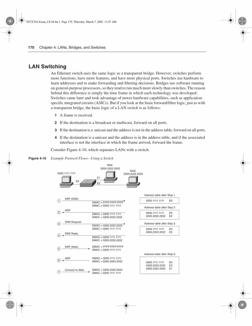
170 Chapter 4: LANs, Bridges, and Switches
LAN SwitchingAn Ethernet switch uses the same logic as a transparent bridge. However, switches perform more functions, have more features, and have more physical ports. Switches use hardware to learn addresses and to make forwarding and filtering decisions. Bridges use software running on general-purpose processors, so they tend to run much more slowly than switches. The reason behind this difference is simply the time frame in which each technology was developed: Switches came later and took advantage of newer hardware capabilities, such as application-specific integrated circuits (ASICs). But if you look at the basic forward/filter logic, just as with a transparent bridge, the basic logic of a LAN switch is as follows:
1 A frame is received.
2 If the destination is a broadcast or multicast, forward on all ports.
3 If the destination is a unicast and the address is not in the address table, forward on all ports.
4 If the destination is a unicast and the address is in the address table, and if the associated interface is not the interface in which the frame arrived, forward the frame.
Consider Figure 4-10, which separates LANs with a switch.
Figure 4-10 Example Protocol Flows—Using a Switch
0200.3333.3333
Web
E0
E1
E2
DNS
DMAC = FFFF.FFFF.FFFF
SMAC = 0200.1111.1111
0200.1111.1111 E0
Address table after Step 1
ARP (DNS)
0200.1111.1111
1
DMAC = 0200.1111.1111
SMAC = 0200.2222.2222
ARP2
DMAC = 0200.2222.2222
SMAC = 0200.1111.1111
DNS Request3
DMAC = 0200.1111.1111
SMAC = 0200.2222.2222
DNS Reply4
DMAC = FFFF.FFFF.FFFF
SMAC = 0200.1111.1111ARP (Web)
5
DMAC = 0200.1111.1111
SMAC = 0200.3333.3333ARP
6
DMAC = 0200.3333.3333
SMAC = 0200.1111.1111Connect to Web
7
0200.2222.2222
0200.1111.1111 E0
0200.2222.2222 E2
Address table after Step 2
0200.1111.1111 E0
0200.2222.2222 E2
Address table after Step 3
0200.1111.1111 E0
0200.2222.2222 E2
0200.3333.3333 E1
Address table after Step 6
04 CCNA Exam_Ch 04.fm.1 Page 170 Thursday, March 7, 2002 11:47 AM

LAN Overview 171
It appears that exactly the same thing happened in Figure 4-10 with a switch as it did in Figure 4-9 using a bridge. The basic logic is similar, but there are some differences. The key physical difference is that each device is attached to a separate port on the switch, whereas, in Figure4-9, the client and the Web server share the same port on the bridge.
The following list provides some additional insights relating to the steps shown in Figure 4-10, including where this figure describes a slightly different action than in Figure 4-9:
1 The PC is preconfigured with the IP address of the DNS. The PC notices that the DNS IP address is in the same subnet as its own IP address; therefore, the PC sends an ARP broadcast hoping to learn the DNS’s MAC address. This frame is forwarded out all other ports by the switch, just like the transparent bridge did in Figure 4-9.
2 The DNS replies to the ARP request with its MAC address, 0200.2222.2222. The destination MAC is 0200.1111.1111, which is already in the address table, so the switch forwards this frame only out port E0.
3 The PC requests name resolution for the Web server by sending a packet with the destination IP address of the DNS. The destination MAC is 0200.2222.2222, which is already in the address table, so the switch forwards this frame only out port E2.
4 The DNS returns the IP address of the Web server to the PC in the DNS reply. The destination MAC is 0200.1111.1111, which is already in the address table, so the switch forwards this frame only out port E0.
5 The PC does not know the Web server’s MAC address, so it sends an ARP broadcast to learn the MAC address. Because it is a MAC broadcast, the switch forwards the frame on all ports.
6 The Web server replies to the ARP, stating that its MAC address is 0200.3333.3333. This frame has a destination MAC of 0200.1111.1111, which is already in the address table, so the switch forwards this frame only out port E0.
7 The PC now can connect to the Web server. This frame has a destination MAC of 0200.3333.3333, which is already in the address table, so the switch forwards this frame only out port E1.
The switch behaves exactly like a transparent bridge would if the bridge used three ports instead of two. The switch learned the MAC addresses by examining the source MAC addresses and made forwarding decisions based on the contents of the address table.
The switch reduces the possibility of collisions. For example, imagine a fourth device, on port E3. If that new device sent a frame to the DNS’s address of 0200.2222.2222 at the same time that the client sent a frame to the Web server (0200.3333.3333), the switch’s basic logic would prevent a collision. For different reasons, the switch prevents a broadcast sent by this new device from colliding with the frame that the client sent to the server. The switch buffers one of the frames until the first frame has been sent and then forwards the second frame.
04 CCNA Exam_Ch 04.fm.1 Page 171 Thursday, March 7, 2002 11:47 AM

172 Chapter 4: LANs, Bridges, and Switches
Collisions can occur on segments attached to switches. Consider Figure 4-11, which shows the same switch but with a shared hub connected to E0.
Figure 4-11 Switch Connected to a Hub
The switch connects to a shared hub, to which the client and the Web server are attached. As you might recall, the shared-media hub does not perform any Layer 2 logic—it just forwards all incoming electrical signals out all other ports. So, if the switch forwarded a frame out E0 to the client, and if the client is sending a frame to the Web server, a collision could occur. However, a frame sent by the client should never collide with frames sent by the DNS because they are on different switch ports. So, a more general statement should be made about switches and collisions:
Switches prevent collisions for ports with only one device connected to the port. If a hub is attached to the switch port with multiple devices attached to the hub, collisions can occur between frames sent by those devices. These frames would not collide with frames sent from devices on other switch ports.
To better discuss LANs, bridging, and switching, a term is needed to describe the set of devices whose frames could collide. Collision domain is the set of LAN interfaces whose frames could collide with each other but not with any other devices in the network. The switch network in Figure 4-10 has created three separate Ethernet segments, and each is a separate collision domain. For example, frames sent by the client in Figure 4-10 would not collide with frames sent by the DNS and the Web server. However, the switch could forward a frame out E0 toward the client at the same instant that the client sends a frame and would create a collision—unless the switch and the client are using full-duplex operation, as covered in the earlier section of this chapter. Regardless, transparent bridges, switches, and routers all create separate collision domains, one per interface.
Figure 4-12 shows a typical example of the definition of collision domains.
E2E0
DNS
0200.2222.2222
Web
0200.3333.3333
Client
0200.1111.1111
SwitchHub
04 CCNA Exam_Ch 04.fm.1 Page 172 Thursday, March 7, 2002 11:47 AM

LAN Overview 173
Figure 4-12 Collision Domains
Bridges and switches forward broadcasts and multicasts on all ports. (Actually, the forwarding of multicasts can be optimized using several switch features, such as the Cisco Group Management Protocol (CGMP), but these are beyond the scope of CCNA.) Because broadcast frames are sent out all ports, a bridge or switch creates only a single broadcast domain. A broadcast domain is the set of devices for which, when one of the devices sends a broadcast, all the other devices receive a copy of the broadcast.
The broadcast domain concept is similar to the concept of collision domains; however, only routers stop the flow of broadcasts. Figure 4-13 provides the broadcast domains for the same network depicted in Figure 4-12.
Figure 4-13 Broadcast Domains
04 CCNA Exam_Ch 04.fm.1 Page 173 Thursday, March 7, 2002 11:47 AM

174 Chapter 4: LANs, Bridges, and Switches
Broadcasts sent by a device in one broadcast domain are not forwarded to devices in another broadcast domain. In this example, there are two broadcast domains. For instance, an ARP sent by a PC on the left is not forwarded by the router. In the old days, the term broadcast firewall described the fact that routers did not forward LAN broadcasts.
General definitions for a collision domain and a broadcast domain are as follows:
A collision domain is a set of network interface cards (NICs) for which a frame sent by one NIC could result in a collision with a frame sent by any other NIC in the same collision domain.
A broadcast domain is a set of NICs for which a broadcast frame sent by one NIC will be received by all other NICs in the broadcast domain.
Engineers design networks keeping broadcast domains in mind because, in most cases, all the devices in a single broadcast domain are also in the same IP subnet. For example, if only bridges and switches had existed in the network in Figure 4-13, and if the router was later added, some IP addresses would have had to be changed. To use the terminology in Chapter 3, two separate address groupings (for example, IP subnets) would be used for IP in Figure 4-13—one for the devices to the left of the router and another for devices to the right of the router. A definition of Layer 3 address groupings on LANs will help you understand VLANs better:
NOTE All devices in the same broadcast domain (Layer 2) typically will be in the same Layer 3 address grouping—in other words, the same IP subnet or same IPX network.
Internal Switching PathsThe internal processing on a switch can decrease latency for frames. Transparent bridges use store-and-forward processing, which means that the entire frame is received before the first bit of the frame is forwarded. Switches can use store-and-forward processing as well as cut-through processing logic. With cut-through processing, the first bits of the frame are sent out the outbound port before the last bit of the incoming frame is received instead of waiting for the entire frame to be received. In other words, as soon as the incoming switch port receives enough of the frame to see the destination MAC address, the frame is transmitted out the appropriate outgoing port to the destination device.
04 CCNA Exam_Ch 04.fm.1 Page 174 Thursday, March 7, 2002 11:47 AM

LAN Overview 175
Cut-through processing can help, and it can hurt. Because the frame check sequence (FCS) is in the Ethernet trailer, a cut-through forwarded frame might have bit errors that the switch will not notice before sending most of the frame. And, of course, if the outbound port is busy, the switch stores the frame until the output port is available, gaining no advantage of store-and-forward switching.
The internal processing algorithms used by switches vary among models and vendors; regardless, the internal processing can be categorized as one of the methods listed in Table 4-6.
Comparison of LAN Segmentation Using Bridges, Switches,and Routers
The CCNA exam tests your ability to compare networks that use bridges, switches, and routers to separate LAN segments. The basic workings of a bridge and a switch have already been covered in this chapter. To compare these three options, first routing logic is covered. Afterward, comparisons will be made among the three options.
Routing is covered more fully in other chapters. For comparison, a router separates two segments in Figure 4-14. The client initiates the same example flow that was used in the earlier examples. Figure 4-14 illustrates a couple of key features of routing.
Table 4-6 Switch Internal Processing
Switching Method Description
Store-and-forward The switch fully receives all bits in the frame (store) before forwarding the frame (forward). This allows the switch to check the FCS before forwarding the frame. (FCS is in the Ethernet trailer.)
Cut-through The switch performs the address table lookup as soon as the destination address field in the header is received. The first bits in the frame can be sent out the outbound port before the final bits in the incoming frame are received. This does not allow the switch to discard frames that fail the FCS check. (FCS is in the Ethernet trailer.)
FragmentFree This performs like cut-through switching, but the switch waits for 64 bytes to be received before forwarding the first bytes of the outgoing frame. According to Ethernet specifications, collisions should be detected during the first 64 bytes of the frame; frames in error because of a collision will not be forwarded. The FCS still cannot be checked.
04 CCNA Exam_Ch 04.fm.1 Page 175 Thursday, March 7, 2002 11:47 AM

176 Chapter 4: LANs, Bridges, and Switches
Figure 4-14 Example Protocol Flows—Using a Router
The flows in Figure 4-14 match the numbers in this list, which explains the meaning and implications of the flows in the figure:
1 The PC is preconfigured with the IP address of the DNS. The PC notices that the IP address of the DNS is on a different subnet, so the PC wants to forward the packet to its default router. However, the PC does not know its default router’s MAC address yet, so it must use ARP to find that router’s MAC address. The ARP broadcast is not forwarded by the router.
2 The router replies to the ARP request with its MAC address, 0200.4444.4444.
0200.3333.3333
0200.4444.4444 0200.5555.5555
Web
Client
E0 E1
DNS
DMAC = FFFF.FFFF.FFFF
SMAC = 0200.1111.1111ARP (Router-E0)
0200.1111.1111
1
DMAC = 0200.1111.1111
SMAC = 0200.4444.4444ARP Reply
2
DMAC = 0200.4444.4444
SMAC = 0200.1111.1111
DNS Request3
DMAC = 0200.1111.1111
SMAC = 0200.4444.4444
DNS Reply4
DMAC = FFFF.FFFF.FFFF
SMAC = 0200.1111.1111ARP (Web)
5
DMAC = 0200.1111.1111
SMAC = 0200.3333.3333ARP
6
DMAC = 0200.3333.3333
SMAC = 0200.1111.1111Connect to Web
7
0200.2222.2222
(Note: Addresses of frames on left-side Ethernet)
04 CCNA Exam_Ch 04.fm.1 Page 176 Thursday, March 7, 2002 11:47 AM
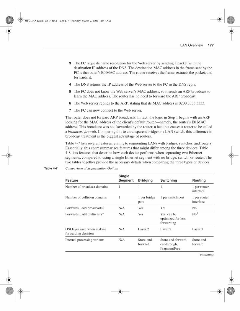
LAN Overview 177
3 The PC requests name resolution for the Web server by sending a packet with the destination IP address of the DNS. The destination MAC address in the frame sent by the PC is the router’s E0 MAC address. The router receives the frame, extracts the packet, and forwards it.
4 The DNS returns the IP address of the Web server to the PC in the DNS reply.
5 The PC does not know the Web server’s MAC address, so it sends an ARP broadcast to learn the MAC address. The router has no need to forward the ARP broadcast.
6 The Web server replies to the ARP, stating that its MAC address is 0200.3333.3333.
7 The PC can now connect to the Web server.
The router does not forward ARP broadcasts. In fact, the logic in Step 1 begins with an ARP looking for the MAC address of the client’s default router—namely, the router’s E0 MAC address. This broadcast was not forwarded by the router, a fact that causes a router to be called a broadcast firewall. Comparing this to a transparent bridge or a LAN switch, this difference in broadcast treatment is the biggest advantage of routers.
Table 4-7 lists several features relating to segmenting LANs with bridges, switches, and routers. Essentially, this chart summarizes features that might differ among the three devices. Table4-8 lists features that describe how each device performs when separating two Ethernet segments, compared to using a single Ethernet segment with no bridge, switch, or router. The two tables together provide the necessary details when comparing the three types of devices.
Table 4-7 Comparison of Segmentation Options
FeatureSingle Segment Bridging Switching Routing
Number of broadcast domains 1 1 1 1 per router interface
Number of collision domains 1 1 per bridge port
1 per switch port 1 per router interface
Forwards LAN broadcasts? N/A Yes Yes No
Forwards LAN multicasts? N/A Yes Yes; can be optimized for less forwarding
No1
OSI layer used when making forwarding decision
N/A Layer 2 Layer 2 Layer 3
Internal processing variants N/A Store-and- forward
Store-and-forward, cut-through, FragmentFree
Store-and- forward
continues
04 CCNA Exam_Ch 04.fm.1 Page 177 Thursday, March 7, 2002 11:47 AM

178 Chapter 4: LANs, Bridges, and Switches
1Routers can forward IP multicast packets, if configured to do so. However, this does not mean that the LAN multicast frame is forwarded.
Table 4-8 lists features that should be interpreted within the following context: If I migrated from a single Ethernet segment to a network with two segments separated by a bridge/switch/router, and if traffic loads and destinations stayed constant, the result would be _______.
Certainly, the most important distinction among the three segmentation methods is their treatment of broadcasts and multicasts. Remembering the concepts of collision domains, broadcast domains, and how each device separates LANs into different domains is one key to understanding campus LAN design and troubleshooting.
LAN Switch ConfigurationCisco expects CCNAs to master the concepts behind LAN switching and VLANs. This mastery includes the ability to configure IOS-based LAN switches using the IOS CLI. This section outlines the similarities of the switch IOS CLI to the router IOS CLI, and contrasts the commands, syntax, and required configuration elements unique to switches.
FeatureSingle Segment Bridging Switching Routing
Frame/packet fragmentation allowed?
N/A No No Yes
Multiple concurrent equal-cost paths to same destination allowed?
N/A No No Yes
Table 4-8 Benefits when Moving from One Ethernet Segment to Multiple Segments Using Bridges, Switches,and Routers
Feature Bridging Switching Routing
Greater cabling distances allowed Yes Yes Yes
Decrease in collisions, assuming equal traffic loads Yes Yes Yes
Decreased adverse impact of broadcasts No No Yes
Decreased adverse impact of multicasts No No, unless mcast optimizations enabled
Yes
Increase in bandwidth Yes Yes Yes
Filtering on Layer 2 header allowed Yes Yes No
Filtering on Layer 3 header allowed No No Yes
Table 4-7 Comparison of Segmentation Options (Continued)
04 CCNA Exam_Ch 04.fm.1 Page 178 Thursday, March 7, 2002 11:47 AM

LAN Switch Configuration 179
Not all Cisco LAN switches provide an IOS CLI interface to the network engineer. Cisco wants its certifications to prove that the candidate knows the technology and can implement it; that proof would be onerous if all switch families’ user interfaces were required on the CCNA exam. This book covers some implementation details and examples on the 1900 series switch, which is the same (and only) switch user interface covered by the ICND course.
The similarities between the 1900 series switch CLI and the router IOS CLI far outnumber the differences. In fact, most of the differences relate to the commands needed on a switch, which are simply not needed on a router. The up arrow retrieves the previous command. The ? key requests help. The Tab key completes a parameter after you have typed in a unique set of beginning characters. The configure terminal command takes you from privileged exec mode to configuration mode. The show running-config command lists the currently used configuration. In fact, when in doubt, assume that the switch and router IOS CLIs are identical. The important differences are mentioned as appropriate in this section.
Basic 1900 Switch ConfigurationOn the Catalyst 1900 switch, three different configuration methods exist:
• Menu-driven interface from the console port
• Web-based Visual Switch Manager (VSM)
• IOS command-line interface (CLI)
As mentioned earlier, this book focuses on using the CLI to configure the switch. Table 4-9 lists the switch commands referred to in this section.
Table 4-9 Commands for Catalyst 1900 Switch Configuration
Command Description
ip address address subnet-mask Sets the IP address for in-band management of the switch
ip default-gateway Sets the default gateway so that the management interface can be reached from a remote network
show ip Displays IP address configuration
show interfaces Displays interface information
mac-address-table permanent mac-address type module/port
Sets a permanent MAC address
mac-address-table restricted static mac-address type module/port src-if-list
Sets a restricted static MAC address
continues
04 CCNA Exam_Ch 04.fm.1 Page 179 Thursday, March 7, 2002 11:47 AM

180 Chapter 4: LANs, Bridges, and Switches
Default 1900 ConfigurationThe default values vary depending on the features of the switch. The following list provides some of the default settings for the Catalyst 1900 switch. (Not all the defaults are shown in this example.)
• IP address: 0.0.0.0
• CDP: Enabled
• Switching mode: FragmentFree
• 100BaseT port: Autonegotiate duplex mode
• 10BaseT port: Half duplex
• Spanning Tree: Enabled
• Console password: None
Numbering Ports (Interfaces)The terms interface and port both are used to describe the physical connectors on the switch hardware. For instance, the show running-config command uses the term interface; the show spantree command uses the term port. The numbering of the interfaces is relatively straightforward; the interface numbering convention for the 1912 and 1924 switches is shown in Table 4-10. Example 4-1 shows three exec commands and highlights the use of the terms interface and port.
Command Description
port secure [max-mac-count count] Sets port security
show mac-address-table {security} Displays the MAC address table; the security option displays information about the restricted or static settings
address-violation {suspend | disable | ignore} Sets the action to be taken by the switch if there is a security address violation
show version Displays version information
copy tftp://host/src_ file {opcode [type module] | nvram}
Copies a configuration file from the TFTP server into NVRAM
copy nvram tftp://host/dst_ file Saves a configuration file to the TFTP server
delete nvram [type module] Removes all configuration parameters and returns the switch to factory default settings
Table 4-9 Commands for Catalyst 1900 Switch Configuration (Continued)
04 CCNA Exam_Ch 04.fm.1 Page 180 Thursday, March 7, 2002 11:47 AM

LAN Switch Configuration 181
Basic IP and Port Duplex Configuration Two features commonly configured during switch installation are TCP/IP support and the setting of duplex on key switch ports. Switches support IP, but in a different way than a router. The switch acts more like a normal IP host, with a single address/mask for the switch and a default router. Each port/interface does not need an IP address because the switch is not performing Layer 3 routing. In fact, if there were no need to manage the switch, IP would not be needed on the switch at all.
Table 4-10 Catalyst 1912 and 1924 Interface/Port Numbering
Catalyst 1912 Catalyst 1924
10BaseT ports 12 total (e0/1 to e0/12) 24 total (e0/1 to e0/24)
AUI port e0/25 e0/25
100BaseT uplink ports fa0/26 (port A)
fa0/27 (port B)
fa0/26 (port A)
fa0/27 (port B)
Example 4-1 show run Output Refers to Port e0/1 as Interface Ethernet 0/1
wg_sw_d#show running-config
Building configuration...Current configuration:!!interface Ethernet 0/1!interface Ethernet 0/2! Portions omitted for brevity...
wg_sw_d#show spantree
Port Ethernet 0/1 of VLAN1 is Forwarding Port path cost 100, Port priority 128 Designated root has priority 32768, address 0090.8673.3340 Designated bridge has priority 32768, address 0090.8673.3340 Designated port is Ethernet 0/1, path cost 0 Timers: message age 20, forward delay 15, hold 1! Portions omitted for brevity...wg_sw_a#show vlan-membership
Port VLAN Membership Type Port VLAN Membership Type------------------------------------------------------------------1 5 Static 13 1 Static 2 1 Static 14 1 Static3 1 Static 15 1 Static
04 CCNA Exam_Ch 04.fm.1 Page 181 Thursday, March 7, 2002 11:47 AM

182 Chapter 4: LANs, Bridges, and Switches
The second feature typically configured at installation time is to preconfigure some ports to always use half- or full-duplex operation rather than allow negotiation. At times, autonegotia-tion can produce unpredictable results. For example, if a device attached to the switch does not support autonegotiation, the Catalyst switch sets the corresponding switch port to half-duplex mode by default. If the attached device is configured for full-duplex operation, a duplex mismatch occurs. To avoid this situation, manually set the duplex parameters of the switch to match the attached device.
Similar to the router IOS, the Catalyst 1900 switch has various configuration modes. Example 4-2 shows the initial configuration of IP and duplex, with the actual prompts showing the familiar exec and configuration modes.
In the example, the duplex could have been set to one of the following modes:
• auto—Sets autonegotiation of duplex mode. This is the default option for 100-MbpsTX ports.
• full—Sets full-duplex mode.
• full-flow-control—Sets full-duplex mode with flow control.
• half—Sets half-duplex mode. This is the default option for 10-Mbps TX ports.
To verify the IP configuration and duplex settings on a given interface, use the show ip and show interface commands, as shown in Example 4-3.
Example 4-2 Configuration Modes for Configuring IP and Duplex
wg_sw_a# configure terminalwg_sw_a(config)#ip address 10.5.5.11 255.255.255.0wg_sw_a(config)#ip default-gateway 10.5.5.3wg_sw_a(config)# interface e0/1wg_sw_a(config-if)#duplex halfwg_sw_a(config-if)#endwg_sw_a
Example 4-3 show ip and show interfaces Output
wg_sw_a#show ip IP address: 10.5.5.11Subnet mask: 255.255.255.0Default gateway: 10.5.5.3Management VLAN: 1Domain name: Name server 1: 0.0.0.0Name server 2: 0.0.0.0HTTP server: EnabledHTTP port: 80RIP: Enabled
wg_sw_a#show interfaces
04 CCNA Exam_Ch 04.fm.1 Page 182 Thursday, March 7, 2002 11:47 AM

LAN Switch Configuration 183
No IP address is in the show interface output because the IP address is associated with the entire switch, not just a single interface. The spanning-tree state of the interface is shown, as is the duplex setting. If duplex was mismatched with the device on the other end, the late collisions counter most likely would increment rapidly.
Viewing and Configuring Entries in the MAC Address TableThe switching/bridging table concept discussed earlier in this chapter is called the MAC address table on the 1900 family of switches. The MAC address table contains dynamic entries, which are learned when the switch receives frames and examines the source MAC address. Two other variations of entries in the MAC address table are important to switch configuration and are outlined along with dynamic entries in the following list:
• Dynamic addresses—MAC addresses are added to the MAC address table through normal bridge/switch processing. In other words, when a frame is received, the source MAC of the frame is associated with the incoming port/interface. These entries in the table time out with disuse (default 300 seconds on a 1900 series switch) and are cleared whenever the entire table is cleared.
Ethernet 0/1 is EnabledHardware is Built-in 10Base-TAddress is 0090.8673.3341MTU 1500 bytes, BW 10000 Kbits802.1d STP State: Forwarding Forward Transitions: 1Port monitoring: DisabledUnknown unicast flooding: EnabledUnregistered multicast flooding: EnabledDescription:Duplex setting: Half duplexBack pressure: Disabled
Receive Statistics Transmit Statistics-------------------------------------- --------------------------------------Total good frames 44841 Total frames 404502Total octets 4944550 Total octets 29591574Broadcast/multicast frames 31011 Broadcast/multicast frames 390913Broadcast/multicast octets 3865029 Broadcast/multicast octets 28478154Good frames forwarded 44832 Deferrals 0Frames filtered 9 Single collisions 0Runt frames 0 Multiple collisions 0No buffer discards 0 Excessive collisions 0 Queue full discards 0Errors: Errors: FCS errors 0 Late collisions 0 Alignment errors 0 Excessive deferrals 0 Giant frames 0 Jabber errors 0 Address violations 0 Other transmit errors 0
Example 4-3 show ip and show interfaces Output (Continued)
04 CCNA Exam_Ch 04.fm.1 Page 183 Thursday, March 7, 2002 11:47 AM

184 Chapter 4: LANs, Bridges, and Switches
• Permanent MAC addresses—Through configuration, a MAC address is associated with a port, just as it would have been associated as a dynamic address. However, permanent entries in the table never time out.
• Restricted-static entries—Through configuration, a MAC address is configured to be associated only with a particular port, with an additional restriction: Frames destined to that MAC address must have entered through a particular set of incoming ports.
Figure 4-15 provides a simple example to show the use of permanent and restricted-static addresses. A popular server (Server 1) is on port E0/3, and there is never a case when its MAC address should not be in the table. The payroll server is also on this switch, and only the company comptroller is allowed access. The configuration and resulting MAC address table are shown in Example 4-4, which follows the figure.
Figure 4-15 MAC Address Table Manipulation—Sample Network
Example 4-4 The MAC Address Table, with Dynamic, Permanent, and Restricted Static Entries
wg_sw_a(config)#mac-address-table permanent 0200.2222.2222 ethernet 0/3wg_sw_a(config)#mac-address-table restricted static 0200.1111.1111 e0/4 e0/1wg_sw_a(config)#Endwg_sw_a#wg_sw_a#show mac-address-tableNumber of permanent addresses : 1Number of restricted static addresses : 1Number of dynamic addresses : 5
Address Dest Interface Type Source Interface List----------------------------------------------------------------------0200.4444.4444 Ethernet 0/1 Dynamic All00E0.1E5D.AE2F Ethernet 0/2 Dynamic All0200.2222.2222 Ethernet 0/3 Permanent All0200.1111.1111 Ethernet 0/4 Static Et0/100D0.588F.B604 FastEthernet 0/26 Dynamic All00E0.1E5D.AE2B FastEthernet 0/26 Dynamic All00D0.5892.38C4 FastEthernet 0/27 Dynamic All
Company �comptroller
Server 1�0200.2222.2222
E0/1
E0/2
E0/3
E0/4 Payroll server�0200.1111.1111
User1
04 CCNA Exam_Ch 04.fm.1 Page 184 Thursday, March 7, 2002 11:47 AM

LAN Switch Configuration 185
In the example, Server 1 is always in the address table as the permanent entry. The payroll server is always in the table off port 0/4, and only devices on port 0/1 are allowed to send frames to it.
Another feature affecting the MAC address table is called port security. Port security is a feature that, when enabled, limits the number of MAC addresses associated with a port in the MAC address table. In other words, there is a preset limit to the number of sources that can forward frames into that switch port.
An example is particularly useful for understanding this concept; the configuration is straightforward. Consider Figure 4-16, which shows a similar configuration to Figure 4-15, except that the finance department has increased to three employees. These three employees are on the same shared hub, which then is cabled to switch port 0/1.
Figure 4-16 Sample Network with Port Security
Port security can be used to restrict port 0/1 so that only three MAC addresses can source frames that enter port 0/1; this is because only the finance department is expected to use the shared hub. Any permanent or restricted-static MAC addresses count against this total of three. Example 4-5 shows a sample configuration, with show commands.
Example 4-5 Port Security Example
wg_sw_a(config)#mac-address-table permanent 0200.2222.2222 ethernet 0/3wg_sw_a(config)#mac-address-table permanent 0200.4444.4444 ethernet 0/1wg_sw_a(config)#mac-address-table restricted static 0200.1111.1111 e0/4 e0/1wg_sw_a(config)#interface ethernet 0/1wg_sw_a(config-if)#port secure max-mac-count 3wg_sw_a(config-if)#Endwg_sw_a#wg_sw_a#show mac-address-tableNumber of permanent addresses : 2Number of restricted static addresses : 1Number of dynamic addresses : 6
Company comptroller�0200.4444.4444
Payroll clerk�0200.5555.5555
Receivables clerk�0200.6666.6666
E0/1
E0/2
E0/4
E0/3
User1
Server 1�0200.2222.2222
Payroll server�0200.1111.1111
continues
04 CCNA Exam_Ch 04.fm.1 Page 185 Thursday, March 7, 2002 11:47 AM

186 Chapter 4: LANs, Bridges, and Switches
In this example, the permanently defined MAC address of 0200.4444.444, the comptroller’s MAC address, is always associated with port e0/1. Notice that the two new employees’ MAC addresses are also in the MAC address table. The port secure max-mac-count 3 command means that a total of three addresses can be learned on this port.
What should the switch do when a fourth MAC address sources a frame that enters E0/1? An address violation occurs when a secured port receives a frame from a new source address that, if added to the MAC table, would cause the switch to exceed its address table size limit for that port. When a port security address violation occurs, the options for action to be taken on a port include suspending, ignoring, or disabling the port. When a port is suspended, it is re-enabled when a frame containing a valid address is received. When a port is disabled, it must be manually re-enabled. If the action is ignored, the switch ignores the security violation and keeps the port enabled.
Use the address-violation global configuration command to specify the action for a port address violation. The syntax for this command is as follows:
address-violation {suspend | disable | ignore}
Use the no address-violation command to set the switch to its default value, which is suspend.
Address Dest Interface Type Source Interface List----------------------------------------------------------------------0200.4444.4444 Ethernet 0/1 Permanent All0200.5555.5555 Ethernet 0/1 Dynamic All0200.6666.6666 Ethernet 0/1 Dynamic All00E0.1E5D.AE2F Ethernet 0/2 Dynamic All0200.2222.2222 Ethernet 0/3 Permanent All0200.1111.1111 Ethernet 0/4 Static Et0/100D0.588F.B604 FastEthernet 0/26 Dynamic All00E0.1E5D.AE2B FastEthernet 0/26 Dynamic All00D0.5892.38C4 FastEthernet 0/27 Dynamic Allwg_sw_a#show mac-address-table securityAction upon address violation : Suspend
Interface Addressing Security Address Table Size--------------------------------------------------------------Ethernet 0/1 Enabled 3Ethernet 0/2 Disabled N/AEthernet 0/3 Disabled N/AEthernet 0/4 Disabled N/AEthernet 0/5 Disabled N/AEthernet 0/6 Disabled N/AEthernet 0/7 Disabled N/AEthernet 0/8 Disabled N/AEthernet 0/9 Disabled N/AEthernet 0/10 Disabled N/AEthernet 0/11 Disabled N/AEthernet 0/12 Disabled N/A
Example 4-5 Port Security Example (Continued)
04 CCNA Exam_Ch 04.fm.1 Page 186 Thursday, March 7, 2002 11:47 AM

LAN Switch Configuration 187
Managing Configuration and System FilesCommands that are used to manage and control the configuration and system software files are slightly different on the 1900 switch family than on IOS-based routers. One of the reasons for the difference is that the switch does not actually run IOS—it has many features similar to IOS, including the IOS CLI, but there are and probably always will be some differences. For example, in Example 4-6, the familiar show version command is used to display uptime and software levels, but it does not show the IOS level because IOS is not running.
Another difference is that when the configuration is changed, the running config is modified but the startup config file in NVRAM is automatically updated. In other words, there is no need for a copy running-config startup-config command on the 1900 family of switches, as there would be on a router. Configuration files can be copied to an external TFTP server, but instead of using the keyword startup-config (used by routers), NVRAM is used.
The syntax of the copy command is slightly different than what was covered in Chapter 2, “Cisco IOS Software Fundamentals,” relating to the router IOS copy command. The syntax of the command used to copy the NVRAM configuration file to host 10.1.1.1 into file mybackup.cfg is copy nvram tftp://10.1.1.1/mybackup.cfg. Unlike the router IOS, the switch IOS CLI will not prompt for the server name or IP address or the name of the file. Instead, the address or server host name and the filename are entered at the command line. The fact that the command does not prompt you is certainly different than with the router IOS. However, the same general syntax is available on the router IOS as of Cisco IOS Software release 12.0. For example, a similar, valid router IOS command would be copy startup-config tftp://10.1.1.1/myrouter.cfg.
Table 4-11 summarizes some of the key differences between the router IOS CLI and the 1900 IOS CLI.
Example 4-6 show version Output Displays Switch Hardware and Cisco IOS Software Information
wg_sw_a#show versionCisco Catalyst 1900/2820 Enterprise Edition SoftwareVersion V9.00.00(12) written from 171.071.114.222Copyright Cisco Systems, Inc. 1993-1999DS2820-1 uptime is 2day(s) 19hour(s) 34minute(s) 41second(s) cisco Catalyst 2820 (486sxl) processor with 2048K/1024K bytes of memoryHardware board revision is 1Upgrade Status: No upgrade currently in progress. Config File Status: No configuration upload/download is in progress 25 Fixed Ethernet/IEEE 802.3 interface(s)SLOT A: FDDI (Fiber DAS Model), Version 00 v1.14 written from 172.031.004.151: valid SLOT B: 100Base-TX(1 Port UTP Model), Version 0 Base Ethernet Address: 00-E0-1E-87-21-40
04 CCNA Exam_Ch 04.fm.1 Page 187 Thursday, March 7, 2002 11:47 AM
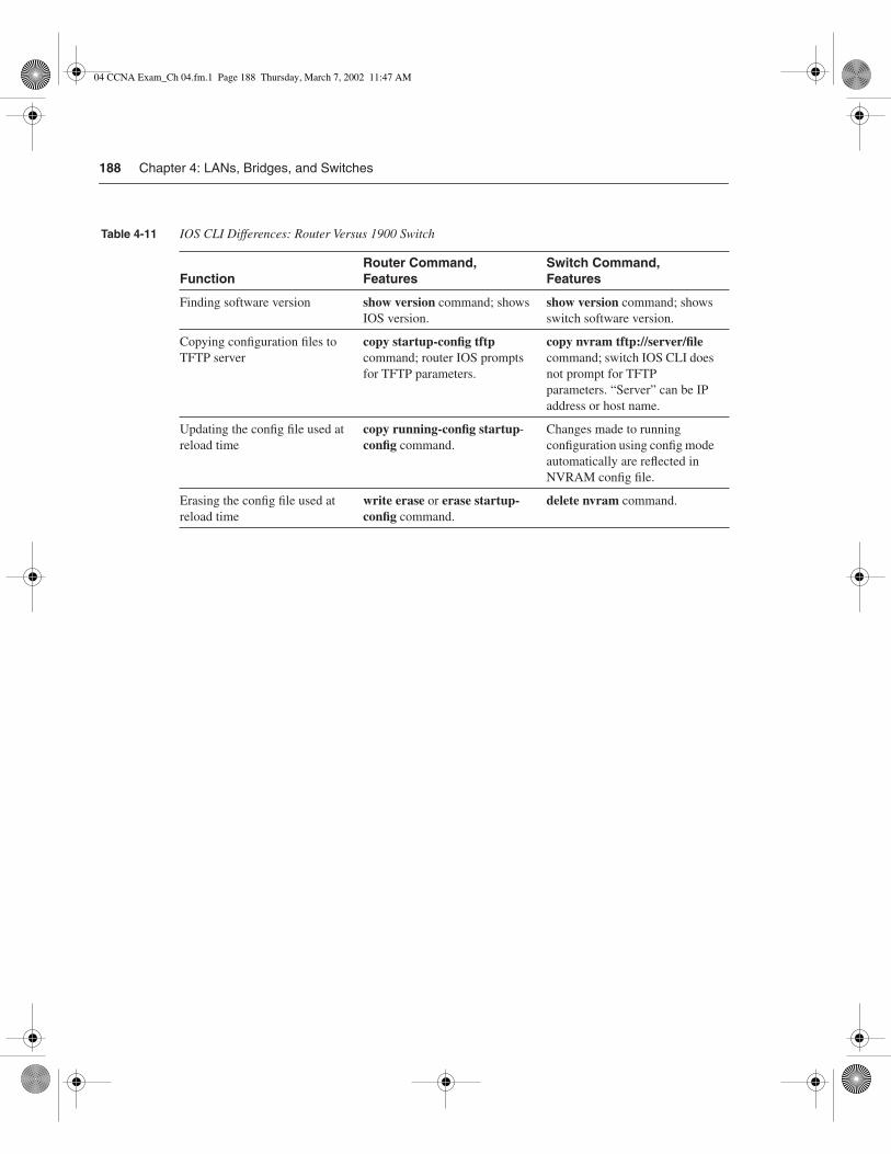
188 Chapter 4: LANs, Bridges, and Switches
Table 4-11 IOS CLI Differences: Router Versus 1900 Switch
FunctionRouter Command, Features
Switch Command, Features
Finding software version show version command; shows IOS version.
show version command; shows switch software version.
Copying configuration files to TFTP server
copy startup-config tftp command; router IOS prompts for TFTP parameters.
copy nvram tftp://server/file command; switch IOS CLI does not prompt for TFTP parameters. “Server” can be IP address or host name.
Updating the config file used at reload time
copy running-config startup- config command.
Changes made to running configuration using config mode automatically are reflected in NVRAM config file.
Erasing the config file used at reload time
write erase or erase startup- config command.
delete nvram command.
04 CCNA Exam_Ch 04.fm.1 Page 188 Thursday, March 7, 2002 11:47 AM

Foundation Summary 189
Foundation Summary
The “Foundation Summary” is a collection of tables and figures that provide a convenient review of many key concepts in this chapter. For those of you already comfortable with the topics in this chapter, this summary could help you recall a few details. For those of you who just read this chapter, this review should help solidify some key facts. For any of you doing your final prep before the exam, these tables and figures will be a convenient way to review the day before the exam.
Table 4-12 summarizes the basic features of Ethernet.
The following list summarizes many of the key features of MAC addresses:
• Unicast MAC addresses address an individual LAN interface card.
• Broadcast MAC addresses address all devices on a LAN.
• Multicast MAC addresses address a subset of the devices on an Ethernet or FDDI LAN.
• Functional MAC addresses identify devices performing a specific IEEE-defined function on Token Ring only.
Figure 4-17 outlines the various LAN framing fields. Focus on the addressing fields, the location of the FCS, and the different “type” fields.
Table 4-12 Summary of Some Basic Ethernet Features
10Base2, 10Base5 Single bus cabled serially between devices using coaxial cable.
10BaseT with a hub One electrical bus shared among all devices creating a single collision domain cabled in a star topology, using twisted-pair cabling.
10BaseT with a switch One electrical bus per switch port, creating multiple collision domains, cabled in a star topology using twisted-pair cabling.
Half duplex Logic that requires a card to only send or receive at a single point in time. Used to avoid collisions.
Full duplex Logic that enables concurrent sending and receiving, allowed when one device is attached to a switch port, ensuring that no collisions can occur.
04 CCNA Exam_Ch 04.fm.1 Page 189 Thursday, March 7, 2002 11:47 AM

190 Chapter 4: LANs, Bridges, and Switches
Figure 4-17 LAN Header Formats
Dest.�
AddressPreamble
Type
Source�
AddressFCSData
Ethernet (DIX)8 6 6 2 Variable 4
IEEE Ethernet (802.3)7 1 6 6 2 1 1 1-2 Variable 4
Dest.�
addressPreamble
DSAP
SSAP
Source�
addressFCSDataSD Length Control
802.3802.2802.3
7 1 6 6 2 1 1 1-2 5 Variable 4
Dest.�
addressPreamble
DSAP
SSAP
Source�
addressFCSDataSD Length Control SNAP
802.3 802.2 802.3
IEEE Token Ring (802.5)
1 1 1 6 6 1 1 1-2 Variable 4 1 1
Dest.�
address
DSAP
SSAP
Source�
addressFCSDataACSD FC Control ED FS
802.5 802.2 802.5
ANSI FDDI4 1 1 6 6 1 1 1-2 Variable 4 .5 1.5
Dest.�
addressPreamble
DSAP
SSAP
Source�
addressFCSDataSD FC Control ED FS
FDDI MAC 802.2 FDDI
4 1 1 6 6 1 1 1-2 5 Variable 4 .5 1.5
Dest.�
addressPreamble
DSAP
SSAP
Source�
addressFCSDataSD FC Control SNAP ED FS
FDDI MAC 802.2 FDDI
1 1 1 6 6 1 1 1-2 5 Variable 4 1 1
Dest.�
address
DSAP
SSAP
Source�
addressFCSDataACSD FC Control SNAP ED FS
802.2 802.5802.5
04 CCNA Exam_Ch 04.fm.1 Page 190 Thursday, March 7, 2002 11:47 AM
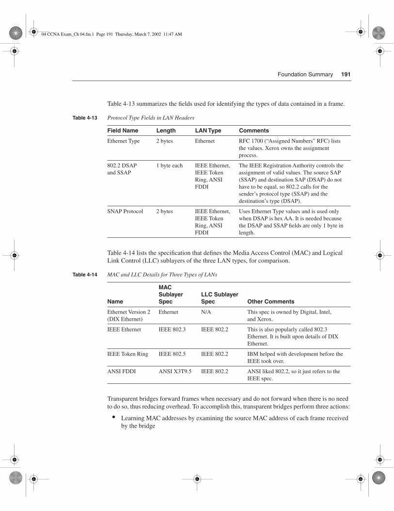
Foundation Summary 191
Table 4-13 summarizes the fields used for identifying the types of data contained in a frame.
Table 4-14 lists the specification that defines the Media Access Control (MAC) and Logical Link Control (LLC) sublayers of the three LAN types, for comparison.
Transparent bridges forward frames when necessary and do not forward when there is no need to do so, thus reducing overhead. To accomplish this, transparent bridges perform three actions:
• Learning MAC addresses by examining the source MAC address of each frame received by the bridge
Table 4-13 Protocol Type Fields in LAN Headers
Field Name Length LAN Type Comments
Ethernet Type 2 bytes Ethernet RFC 1700 (“Assigned Numbers” RFC) lists the values. Xerox owns the assignment process.
802.2 DSAPand SSAP
1 byte each IEEE Ethernet, IEEE Token Ring, ANSI FDDI
The IEEE Registration Authority controls the assignment of valid values. The source SAP (SSAP) and destination SAP (DSAP) do not have to be equal, so 802.2 calls for the sender’s protocol type (SSAP) and the destination’s type (DSAP).
SNAP Protocol 2 bytes IEEE Ethernet, IEEE Token Ring, ANSI FDDI
Uses Ethernet Type values and is used only when DSAP is hex AA. It is needed because the DSAP and SSAP fields are only 1 byte in length.
Table 4-14 MAC and LLC Details for Three Types of LANs
Name
MAC Sublayer Spec
LLC Sublayer Spec Other Comments
Ethernet Version 2 (DIX Ethernet)
Ethernet N/A This spec is owned by Digital, Intel,and Xerox.
IEEE Ethernet IEEE 802.3 IEEE 802.2 This is also popularly called 802.3 Ethernet. It is built upon details of DIX Ethernet.
IEEE Token Ring IEEE 802.5 IEEE 802.2 IBM helped with development before the IEEE took over.
ANSI FDDI ANSI X3T9.5 IEEE 802.2 ANSI liked 802.2, so it just refers to the IEEE spec.
04 CCNA Exam_Ch 04.fm.1 Page 191 Thursday, March 7, 2002 11:47 AM

192 Chapter 4: LANs, Bridges, and Switches
• Deciding when to forward a frame or when to filter (not forward) a frame, based on the destination MAC address
• Creating a loop-free environment with other bridges by using the Spanning Tree Protocol
Figures 4-18 and 4-19 detail the concepts of a collision domain and a broadcast domain.
Figure 4-18 Collision Domains
Figure 4-19 Broadcast Domains
04 CCNA Exam_Ch 04.fm.1 Page 192 Thursday, March 7, 2002 11:47 AM

Foundation Summary 193
General definitions for collision domain and broadcast domain are as follows:
A collision domain is a set of network interface cards (NICs) for which a frame sent by one NIC could result in a collision with a frame sent by any other NIC in the same collision domain.
A broadcast domain is a set of NICs for which a broadcast frame sent by one NIC will be received by all other NICs in the broadcast domain.
Table 4-15 lists the internal processing methods of LAN switches.
Table 4-16 lists several features relating to segmenting LANs with bridges, switches, and routers.
Table 4-15 Switch Internal Processing
Switching Method Description
Store-and-forward The switch fully receives all bits in the frame (store) before forwarding the frame (forward). This allows the switch to check the FCS before forwarding the frame. (FCS is in the Ethernet trailer.)
Cut-through The switch performs the address table lookup as soon as the destination address field in the header is received. The first bits in the frame can be sent out the outbound port before the final bits in the incoming frame are received. This does not allow the switch to discard frames that fail the FCS check. (FCS is in the Ethernet trailer.)
FragmentFree This performs like cut-through switching, but the switch waits for 64 bytes to be received before forwarding the first bytes of the outgoing frame. According to Ethernet specifications, collisions should be detected during the first 64 bytes of the frame; frames in error because of a collision will not be forwarded. The FCS still cannot be checked.
Table 4-16 Comparison of Segmentation Options
FeatureSingle Segment Bridging Switching Routing
Number of broadcast domains 1 1 1 1 per router interface
Number of collision domains 1 1 per bridge port 1 per switch port 1 per router interface
Forwards LAN broadcasts? N/A Yes Yes No
Forwards LAN multicasts? N/A Yes Yes; can be optimized for less forwarding
No1
OSI layer used when making forwarding decision
N/A Layer 2 Layer 2 Layer 3
continues
04 CCNA Exam_Ch 04.fm.1 Page 193 Thursday, March 7, 2002 11:47 AM
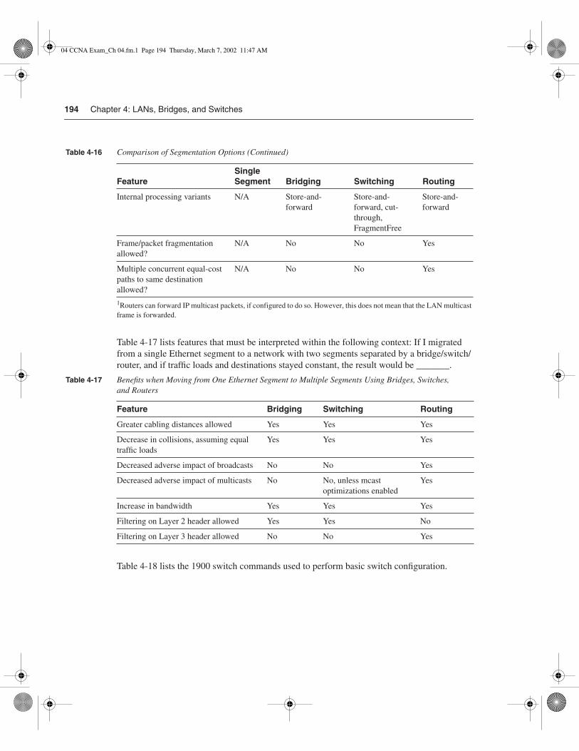
194 Chapter 4: LANs, Bridges, and Switches
1Routers can forward IP multicast packets, if configured to do so. However, this does not mean that the LAN multicast frame is forwarded.
Table 4-17 lists features that must be interpreted within the following context: If I migrated from a single Ethernet segment to a network with two segments separated by a bridge/switch/router, and if traffic loads and destinations stayed constant, the result would be _______.
Table 4-18 lists the 1900 switch commands used to perform basic switch configuration.
FeatureSingle Segment Bridging Switching Routing
Internal processing variants N/A Store-and- forward
Store-and- forward, cut- through, FragmentFree
Store-and- forward
Frame/packet fragmentation allowed?
N/A No No Yes
Multiple concurrent equal-cost paths to same destination allowed?
N/A No No Yes
Table 4-17 Benefits when Moving from One Ethernet Segment to Multiple Segments Using Bridges, Switches,and Routers
Feature Bridging Switching Routing
Greater cabling distances allowed Yes Yes Yes
Decrease in collisions, assuming equal traffic loads
Yes Yes Yes
Decreased adverse impact of broadcasts No No Yes
Decreased adverse impact of multicasts No No, unless mcast optimizations enabled
Yes
Increase in bandwidth Yes Yes Yes
Filtering on Layer 2 header allowed Yes Yes No
Filtering on Layer 3 header allowed No No Yes
Table 4-16 Comparison of Segmentation Options (Continued)
04 CCNA Exam_Ch 04.fm.1 Page 194 Thursday, March 7, 2002 11:47 AM

Foundation Summary 195
Table 4-19 lists the port-numbering conventions for the 1912 and 1924 series switches.
Table 4-18 Commands for Catalyst 1900 Switch Configuration
Command Description
ip address address subnet-mask Sets the IP address for in-band management of the switch
ip default-gateway Sets the default gateway so that the management interface can be reached from a remote network
show ip Displays IP address configuration
show interfaces Displays interface information
mac-address-table permanentmac-address type module/port
Sets a permanent MAC address
mac-address-table restricted staticmac-address type module/port src-if-list
Sets a restricted static MAC address
port secure [max-mac-count count] Sets port security
show mac-address-table {security} Displays the MAC address table; the security option displays information about the restricted or static settings
address-violation {suspend | disable| ignore}
Sets the action to be taken by the switch if there is a security address violation
show version Displays version information
copy tftp://host/src_ file {opcode[type module] | nvram}
Copies a configuration file from the TFTP server into NVRAM
copy nvram tftp://host/dst_ file Saves a configuration file to the TFTP server
delete nvram [type module] Removes all configuration parameters and returns the switch to factory default settings
04 CCNA Exam_Ch 04.fm.1 Page 195 Thursday, March 7, 2002 11:47 AM

196 Chapter 4: LANs, Bridges, and Switches
Table 4-20 lists the key differences between the switch CLI and the router CLI.
Table 4-19 Catalyst 1912 and 1924 Interface/Port Numbering
Catalyst 1912 Catalyst 1924
10BaseT ports 12 total (e0/1 to e0/12) 24 total (e0/1 to e0/24)
AUI port e0/25 e0/25
100BaseT uplink ports fa0/26 (port A)
fa0/27 (port B)
fa0/26 (port A)
fa0/27 (port B)
Table 4-20 IOS CLI Differences: Router Versus 1900 Switch
Function Router Command, Features Switch Command, Features
Finding software version show version command; shows IOS version
show version command; shows switch software version.
Copying configuration files to TFTP server
copy startup-config tftp command; router IOS prompts for TFTP parameters
copy nvram tftp://server/file command; switch IOS CLI does not prompt for TFTP parameters. “Server” can be IP address or host name.
Updating the config file used at reload time
copy running-config startup- config command
Changes made to running configuration using config mode automatically are reflected in NVRAM config file.
Erasing the config file used at reload time
write erase or erase startup- config command
delete nvram command.
04 CCNA Exam_Ch 04.fm.1 Page 196 Thursday, March 7, 2002 11:47 AM

Q&A 197
Q&A
As mentioned in Chapter 1, “All About the Cisco Certified Network Associate Certification,” the questions and scenarios in this book are more difficult than what you should experience on the actual exam. The questions do not attempt to cover more breadth or depth than the exam; however, they are designed to make sure that you know the answer. Rather than allowing you to derive the answer from clues hidden inside the question itself, the questions challenge your understanding and recall of the subject. Questions from the “Do I Know This Already?” quiz from the beginning of the chapter are repeated here to ensure that you have mastered the chapter’s topic areas. Hopefully, these questions will help limit the number of exam questions on which you narrow your choices to two options and then guess.
The answers to these questions can be found in Appendix A.
1 What do the letters MAC stand for? What other terms have you heard to describe the same or similar concept?
_______________________________________________________________________
_______________________________________________________________________
_______________________________________________________________________
2 Name two benefits of LAN segmentation using transparent bridges.
_______________________________________________________________________
_______________________________________________________________________
_______________________________________________________________________
3 What routing protocol does a transparent bridge use to learn about Layer 3 addressing groupings?
_______________________________________________________________________
_______________________________________________________________________
_______________________________________________________________________
4 If a Fast Ethernet NIC is currently receiving a frame, can it begin sending a frame?
_______________________________________________________________________
_______________________________________________________________________
_______________________________________________________________________
04 CCNA Exam_Ch 04.fm.1 Page 197 Thursday, March 7, 2002 11:47 AM

198 Chapter 4: LANs, Bridges, and Switches
5 Why did Ethernet networks’ performance improve with the advent of bridges?
______________________________________________________________________
______________________________________________________________________
______________________________________________________________________
6 Why did Ethernet networks’ performance improve with the advent of switches?
______________________________________________________________________
______________________________________________________________________
______________________________________________________________________
7 What are two key differences between a 10-Mbps NIC and a 10/100 NIC?
______________________________________________________________________
______________________________________________________________________
______________________________________________________________________
8 Assume that a building has 100 devices attached to the same Ethernet. These users then are migrated onto two separate shared Ethernet segments, each with 50 devices, with a transparent bridge between them. List two benefits that would be derived for a typical user.
______________________________________________________________________
______________________________________________________________________
______________________________________________________________________
9 What standards body owns the process of ensuring unique MAC addresses worldwide?
______________________________________________________________________
______________________________________________________________________
______________________________________________________________________
10 Assume that a building has 100 devices attached to the same Ethernet. These devices are migrated to two different shared Ethernet segments, each with 50 devices. The two segments are connected to a Cisco LAN switch to allow communication between the two sets of users. List two benefits that would be derived for a typical user.
______________________________________________________________________
______________________________________________________________________
______________________________________________________________________
04 CCNA Exam_Ch 04.fm.1 Page 198 Thursday, March 7, 2002 11:47 AM

Q&A 199
11 Name two of the methods of internal switching on typical switches today. Which provides less latency for an individual frame?
_______________________________________________________________________
_______________________________________________________________________
_______________________________________________________________________
12 What is the distance limitation of a single cable for 10BaseT? 100BaseTX?
_______________________________________________________________________
_______________________________________________________________________
_______________________________________________________________________
13 Describe how a transparent bridge decides whether it should forward a frame, and tell how it chooses the interface out which to forward the frame.
_______________________________________________________________________
_______________________________________________________________________
_______________________________________________________________________
14 How fast is Fast Ethernet?
_______________________________________________________________________
_______________________________________________________________________
_______________________________________________________________________
15 How does a transparent bridge build its address table?
_______________________________________________________________________
_______________________________________________________________________
_______________________________________________________________________
16 How many bytes long is a MAC address?
_______________________________________________________________________
_______________________________________________________________________
_______________________________________________________________________
04 CCNA Exam_Ch 04.fm.1 Page 199 Thursday, March 7, 2002 11:47 AM

200 Chapter 4: LANs, Bridges, and Switches
17 Assume that a building has 100 devices attached to the same Ethernet. These users then are migrated onto two separate Ethernet segments, each with 50 devices and separated by a router. List two benefits that would be derived for a typical user.
______________________________________________________________________
______________________________________________________________________
______________________________________________________________________
18 Does a bridge/switch examine just the incoming frame’s source MAC, the destination MAC, or both? Why does it examine the one(s) that it examines?
______________________________________________________________________
______________________________________________________________________
______________________________________________________________________
19 Define the term collision domain.
______________________________________________________________________
______________________________________________________________________
______________________________________________________________________
20 Define the difference between broadcast and multicast MAC addresses.
______________________________________________________________________
______________________________________________________________________
______________________________________________________________________
21 Excluding the preamble and starting delimiter fields, but including all other Ethernet headers and trailers, what is the maximum number of bytes in an Ethernet frame?
______________________________________________________________________
______________________________________________________________________
______________________________________________________________________
22 Define the term broadcast domain.
______________________________________________________________________
______________________________________________________________________
______________________________________________________________________
04 CCNA Exam_Ch 04.fm.1 Page 200 Thursday, March 7, 2002 11:47 AM

Q&A 201
23 Describe the benefits of creating 3 VLANs of 25 ports each, versus a single VLAN of 75 ports, in each case using a single switch. Assume that all ports are switched ports (each port is a different collision domain).
_______________________________________________________________________
_______________________________________________________________________
_______________________________________________________________________
24 Explain the function of the loopback and collision-detection features of an Ethernet NIC in relation to half-duplex and full-duplex operations.
_______________________________________________________________________
_______________________________________________________________________
_______________________________________________________________________
25 How many IP addresses must be configured for network management on a Cisco Catalyst 1900 switch if eight ports are to be used and with three VLANs?
_______________________________________________________________________
_______________________________________________________________________
_______________________________________________________________________
26 What command on a 1900 series switch would cause the switch to block frames destined to 0200.7777.7777 entering interface 0/5 from going out port 0/6?
_______________________________________________________________________
_______________________________________________________________________
_______________________________________________________________________
27 What Catalyst 1900 switch command displays the version of IOS running in the switch?
_______________________________________________________________________
_______________________________________________________________________
_______________________________________________________________________
28 What does the Catalyst 1900 switch command address violation disable do?
_______________________________________________________________________
_______________________________________________________________________
_______________________________________________________________________
04 CCNA Exam_Ch 04.fm.1 Page 201 Thursday, March 7, 2002 11:47 AM
202 Chapter 4: LANs, Bridges, and Switches
29 What command erases the startup config in a Catalyst 1900 switch?
______________________________________________________________________
______________________________________________________________________
______________________________________________________________________
30 Configuration is added to the running configuration in RAM when commands aretyped in Catalyst 1900 configuration mode. What causes these commands to be savedinto NVRAM?
______________________________________________________________________
______________________________________________________________________
______________________________________________________________________
31 How do exec and configuration commands refer to the two Fast Ethernet ports on a Catalyst 1912 switch?
______________________________________________________________________
______________________________________________________________________
______________________________________________________________________
32 What Catalyst 1900 switch command displays the switching table?
______________________________________________________________________
______________________________________________________________________
______________________________________________________________________
04 CCNA Exam_Ch 04.fm.1 Page 202 Thursday, March 7, 2002 11:47 AM

Scenario 4-1: LAN Switch Configuration 203
Scenarios
Scenario 4-1: LAN Switch ConfigurationYour job is to deploy a new LAN switch at a remote site. Figure 4-20 depicts the network. Perform the activities in the list that follows the diagram.
Figure 4-20 Scenario 4-1: Basic LAN Switch Configuration
Larry
Archibald
Junior
Jerry
Jimmy
R2
Sw12
04 CCNA Exam_Ch 04.fm.1 Page 203 Thursday, March 7, 2002 11:47 AM

204 Chapter 4: LANs, Bridges, and Switches
1 Clear the saved configuration before starting.
2 Assign IP address 172.16.2.254, mask 255.255.255.0, to SW12. Assign it an appropriate default gateway, and configure SW12 to use a DNS, which is at 172.16.1.250.
3 Assign a host name of SW12.
4 Choose port numbers to be used for each device, as if you were planning the physical installation. Write down these numbers on the diagram.
5 Configure so that the router uses 100-Mbps full-duplex operation.
6 Configure Archibald’s MAC address so that it never leaves the address table.
7 Configure Junior so it gets frames only from Jimmy and Jerry.
8 List the commands that you would use to verify all of these features.
9 Identify the command that you would use to examine the running configuration, saved configuration, and IOS level.
10 Describe the contents of the address table after all devices have sent at least one frame.
Scenario 4-2: LAN Switch ConceptsIn this scenario, you will answer some questions about a simple network diagram. Figure 4-21 depicts the network. Answer the questions that follow the diagram.
Figure 4-21 Scenario 4-2: Basic LAN Switch Concepts
Hub1
Hub2
PC2 PC3
PC4 PC5
PC14 PC15
PC11 PC12 PC13
0
1 2
Sw20 1 2
3
4
0 1 23
FA0 FA1
PC1
R1Sw1
1 2
0
4
04 CCNA Exam_Ch 04.fm.1 Page 204 Thursday, March 7, 2002 11:47 AM

Scenario 4-2: LAN Switch Concepts 205
1 How many collision domains exist in this network?
2 How many broadcast domains exist in this network?
3 Assuming that all cards, switches, and router interfaces are 10/100 cards, how many ports total on each switch could run full duplex?
4 Assuming that all cards, switches, and router interfaces are 10/100 cards, how many ports total on each switch could run 100 Mbps?
5 The first frames to flow in this network are the following: PC5 sends an IP ARP, encapsulated in an Ethernet frame, to its default gateway, which is R1’s FA0 interface’s IP address. The Ethernet frame containing the ARP reply is the second frame. Describe what ports each frame is sent out. Use Table 4-21 to list where the frame flowed, or is draw on the diagram. If you use the table, write “received” if the frame was received in that port, or write “sent” if the frame was sent out that port.
Table 4-21 List of Hub/Switch/Router Ports for Figure 4-21
Port
Was Frame 1 Either Received in or Sent outThis Port?
Was Frame 2 Either Received in or Sent outThis Port?
Hub1—port 0
Hub1—port 1
Hub1—port 2
SW1—port 0
SW1—port 1
SW1—port 2
SW1—port 3
SW1—port 4
Hub2—port 0
Hub2—port 1
Hub2—port 2
SW2—port 0
SW2—port 1
SW2—port 2
SW2—port 3
SW2—port 4
R1—FA0
R1—FA1
04 CCNA Exam_Ch 04.fm.1 Page 205 Thursday, March 7, 2002 11:47 AM

206 Chapter 4: LANs, Bridges, and Switches
Scenario Answers
Answers to Scenario 4-1: LAN Switch ConfigurationThis scenario should have forced you to perform basic LAN configuration. Figure 4-22 lists the port numbers and MAC addresses used for the solution. Example 4-7 lists the output from actually performing these steps sequentially on a 1900 series switch. An explanation of the steps follows the example.
Figure 4-22 MAC Address Format
Example 4-7 Scenario 4-1 Configuration and show Commands
#delete nvramThis command resets the switch with factory defaults. All systemparameters will revert to their default factory settings. All staticand dynamic addresses will be removed.
Reset system with factory defaults, [Y]es or [N]o? Yes
(some time passes…)Catalyst 1900 Management ConsoleCopyright (c) Cisco Systems, Inc. 1993-1999All rights reserved.Enterprise Edition SoftwareEthernet Address: 00-10-29-DE-7B-C0
PCA Number: 73-2241-04PCA Serial Number: SAD02030649
Larry
Archibald
Junior
Jerry
Jimmy
R2
Sw12
0/27
172.16.2.2
0/1
0/2
0/3
0/4
0/5
04 CCNA Exam_Ch 04.fm.1 Page 206 Thursday, March 7, 2002 11:47 AM

Answers to Scenario 4-1: LAN Switch Configuration 207
Model Number: WS-C1924C-ENSystem Serial Number: FAA0208T0BH-------------------------------------------------
1 user(s) now active on Management Console.
User Interface Menu
[M] Menus [K] Command Line [I] IP Configuration [P] Console Password
Enter Selection: K
CLI session with the switch is open. To end the CLI session, enter [Exit].
>enable
#configure terminalEnter configuration commands, one per line. End with CNTL/Z(config)#ip address 172.16.2.254 255.255.255.0(config)#ip default-gateway 172.16.2.2(config)#hostname SW12SW12(config)#interface fastethernet 0/27SW12(config-if)#duplex ? auto Enable auto duplex configuration full Force full duplex operation full-flow-control Force full duplex with flow control half Force half duplex operationSW12(config-if)#duplex fullSW12(config-if)#interface e 0/1SW12(config-if)#duplex autoError: Invalid configuration for this interfaceSW12(config)#mac-address-table permanent 0000.0c3E.5183 e 0/2SW12(config)#mac-address-table restricted static 0100.3333.3333 e0/3 e0/4 e0/512(config)#exitSW12#show mac-address-table Number of permanent addresses : 1Number of restricted static addresses : 1Number of dynamic addresses : 2
Address Dest Interface Type Source Interface List----------------------------------------------------------------------0000.0C3E.5183 Ethernet 0/2 Permanent All0100.3333.3333 Ethernet 0/3 Static Et0/4,Et0/50000.0C4A.8BCA Ethernet 0/1 Dynamic All0004.5A0A.EBBE Ethernet 0/6 Dynamic AllSW12#show versionCisco Catalyst 1900/2820 Enterprise Edition SoftwareVersion V9.00.04
Example 4-7 Scenario 4-1 Configuration and show Commands (Continued)
continues
04 CCNA Exam_Ch 04.fm.1 Page 207 Thursday, March 7, 2002 11:47 AM

208 Chapter 4: LANs, Bridges, and Switches
Copyright (c) Cisco Systems, Inc. 1993-1999SW12 uptime is 0day(s) 00hour(s) 05minute(s) 45second(s) cisco Catalyst 1900 (486sxl) processor with 2048K/1024K bytes of memoryHardware board revision is 1Upgrade Status: No upgrade currently in progress. Config File Status: No configuration upload/download is in progress 27 Fixed Ethernet/IEEE 802.3 interface(s)Base Ethernet Address: 00-10-29-DE-7B-C0
SW12#show running-config Building configuration...Current configuration:!mac-address-table permanent 0000.0C3E.5183 Ethernet 0/2mac-address-table restricted static 0100.3333.3333 Ethernet 0/3 Ethernet 0/4 Ethernet 0/5!hostname "SW12"!ip address 172.16.2.254 255.255.255.0ip default-gateway 172.16.2.2ip domain-name "atl.mediaone.net"ip name-server 24.88.1.66ip name-server 24.88.1.67!interface Ethernet 0/1
!interface Ethernet 0/2
!interface Ethernet 0/3!interface Ethernet 0/4!interface Ethernet 0/5!interface Ethernet 0/6!interface Ethernet 0/7!interface Ethernet 0/8!interface Ethernet 0/9!interface Ethernet 0/10!interface Ethernet 0/11!interface Ethernet 0/12!
Example 4-7 Scenario 4-1 Configuration and show Commands (Continued)
04 CCNA Exam_Ch 04.fm.1 Page 208 Thursday, March 7, 2002 11:47 AM

Answers to Scenario 4-1: LAN Switch Configuration 209
Example 4-7 begins with the startup config being deleted using the delete nvram configuration. Because only one configuration file exists, the command also clears the running config. As shown in the example, some time passes (about 10 seconds) and then the console is presented with the usual option for the menu system or the command line. In this case, the command line is chosen. The delete nvram command does clear the MAC table and put everything in VLAN 1 (the default), so it interrupts typical switch operation. The global commands for setting the IP address, default gateway, and host name are straightforward.
interface Ethernet 0/13!interface Ethernet 0/14!interface Ethernet 0/15!interface Ethernet 0/16!interface Ethernet 0/17!interface Ethernet 0/18!interface Ethernet 0/19!interface Ethernet 0/20!interface Ethernet 0/21!interface Ethernet 0/22!interface Ethernet 0/23!interface Ethernet 0/24!interface Ethernet 0/25!interface FastEthernet 0/26!interface FastEthernet 0/27 duplex full!line consoleendSW12#show startup ^% Invalid input detected at '^' marker.SW12#show config ^% Invalid input detected at '^' marker.SW12#
Example 4-7 Scenario 4-1 Configuration and show Commands (Continued)
04 CCNA Exam_Ch 04.fm.1 Page 209 Thursday, March 7, 2002 11:47 AM

210 Chapter 4: LANs, Bridges, and Switches
You need to know some information about 1900 switch architecture to get the configuration completely correct. For example, the 1900 has only 10-Mbps or 100-Mbps ports, but no autosensing 10/100 ports. Also, full-duplex operation is supported only on 100-Mbps ports.So, the only ports that can do any negotiation are the two uplink ports, namely 0/26 and 0/27. (To prove the point, in Example 4-7, the duplex auto command failed on interface E 0/1.) In this case, 0/27 is used to connect to R2, and it is set to full-duplex mode.
The static entry in the MAC table and the restricted port pose the most challenging part of the configuration. Although the entry is indeed static, the term used for Cisco IOS switches for statically configured entries in the MAC table is permanent. So, the mac-address-table permanent 0000.0c3E.5183 e 0/2 command permanently places the MAC address in the MAC table, off port e 0/2. The command that restricts traffic to Junior so that only Jimmy and Jerry can reach him is mac-address-table restricted static 0100.3333.3333 e0/3 e0/4 e0/5. The show mac-address-table command lists the results of these two commands—one permanent entry and one MAC address with restrictions so that it is accessible only from ports 0/4 and 0/5.
Finally, you view the configuration file with the show running-config command. Because there is only one config file, there is no need for a show startup-config command or a show config command. Notice that both commands are rejected at the end of Example 4-7.
Answers to Scenario 4-2: LAN Switch ConceptsThis scenario tests your recollection of a few of the core concepts for LAN switching. The answers are listed in succession:
1 Ten collision domains exist in the network for this scenario. Routers and switches separate LANs into separate collision domains, but shared hubs do not. In this diagram, each switch port and the device(s) connected to it form the individual collision domains.
2 Two broadcast domains exist in this network. Switches and hubs do not separate the LAN segments into different broadcast domains, but routers do. The two broadcast domains consist of the devices to the left of R1 and the devices to the right of R1.
3 Eight total switch ports could run full-duplex operation. Port 3 on each switch could not because there is a shared hub attached to this port, so collisions could happen. When collisions could happen, FDX is not allowed.
4 All ten switch ports could run 100 Mbps Fast Ethernet. Router FastEthernet interfaces support 100 Mbps, and the assumption was made that all the PCs support 100 Mbps. Shared hubs also can support 100 Mbps. So, all switch ports could run at 100 Mbps, but port 3 on each switch could not use full-duplex operation.
5 Figures 4-23 and 4-24 depict the flows of frame 1 and frame 2. Frame 1 has a source of PC5 and a broadcast destination. Frame 2 has a source of R1’s FA0 MAC address and a destination of PC5’s MAC address. Table 4-22 also describes the ports that the frames came in and out on their journeys, respectively.
04 CCNA Exam_Ch 04.fm.1 Page 210 Thursday, March 7, 2002 11:47 AM

Answers to Scenario 4-2: LAN Switch Concepts 211
Figure 4-23 Scenario 4-2: Path of First Frame in Question Number 5
Figure 4-24 Scenario 4-2: Path of Second Frame in Question Number 5
Table 4-22 Table of Incoming and Outgoing Ports for Frames in Scenario 4-2, Question 5
PortWas Frame 1 Either Received in or Sent out This Port?
Was Frame 2 Either Received in or Sent out This Port?
Hub1—port 0 Sent Received
Hub1—port 1 Sent Sent
Hub1—port 2 Received Sent
SW1—port 0 Sent
Hub1
Hub2
PC2 PC3
PC4 PC5
PC14 PC15
PC11 PC12 PC13
0
1 2
Sw20 1 2
3
4
0 1 23
FA0 FA1
PC1
R1Sw1
1 2
0
4
Hub1
Hub2
PC2 PC3
PC4 PC5
PC14 PC15
PC11 PC12 PC13
0
1 2
Sw20 1 2
3
4
0 1 23
FA0 FA1
PC1
R1Sw1
1 2
0
4
continues
04 CCNA Exam_Ch 04.fm.1 Page 211 Thursday, March 7, 2002 11:47 AM

212 Chapter 4: LANs, Bridges, and Switches
Frame 1 is a broadcast, so it must flow throughout the broadcast domain. So, Hub1 and Switch1 forward out all ports. R1, however, is the boundary of the broadcast domain, so R1 does not forward the broadcast. R1 replies to the ARP and encapsulates it in an Ethernet frame. This second frame has a destination of PC5’s MAC address. SW1 learned that PC5’s MAC is out its port 3. The hub did not learn anything because it does not keep an address table. So, R1 sends the second frame to PC5. SW1 forwards only out port 3, according to its address table. The hub still forwards out all ports.
PortWas Frame 1 Either Receivedin or Sent out This Port?
Was Frame 2 Either Receivedin or Sent out This Port?
SW1—port 1 Sent
SW1—port 2 Sent
SW1—port 3 Received Sent
SW1—port 4 Sent Received
Hub2—port 0
Hub2—port 1
Hub2—port 2
SW2—port 0
SW2—port 1
SW2—port 2
SW2—port 3
SW2—port 4
R1—FA0 Received Sent
R1—FA1
Table 4-22 Table of Incoming and Outgoing Ports for Frames in Scenario 4-2, Question 5 (Continued)
04 CCNA Exam_Ch 04.fm.1 Page 212 Thursday, March 7, 2002 11:47 AM

04 CCNA Exam_Ch 04.fm.1 Page 213 Thursday, March 7, 2002 11:47 AM