cd brush plating replacement - national defense industrial...
TRANSCRIPT

E2S2 2010, Denver Colorado Presentation # 9813 - Pollution Prevention - 17 June 2010
Paul Brezovec, CEFConcurrent Technologies Corp.
Elizabeth Berman, Ph.D.Air Force Research Laboratory
Materials & Manufacturing Directorate
Eileen SchmuraConcurrent Technologies Corp.
Indium Alloy as Cadmium Brush Plating
Replacement

Project Details
• Second Year of Effort
• Numerous Agencies / Companies Involved
(partial list)
– Air Force Research Laboratory (AFRL)
– Air Force Depots
– NAVSEA (Naval Avionics Support Equipment Appraisal)
– Concurrent Technologies Corporation (CTC)
– Boeing
– Matco Associates
– Harris Consulting

Problem Statement
• Cadmium (Cd) plating is used on steel mating surfaces
on a Department of Defense (DoD) Weapon System
– Federal regulations of Cd have increased to protect human
health and the environment
– Rate of phase-out and cost have also increased
• Maintenance, repair, and overhaul operations of a
component of the same weapon system have recently
been transitioned to a different DoD facility
– New DoD facility had previously eliminated Cd plating
– DoD facility requested the United States Air Force (USAF) for
replacement coating in the weapon’s component
3

4
Mating surfaces have dimensional tolerances
Iron oxide is insulating and expands part volume
Cd oxide is semi-conductive and non-voluminous
Conduct Electricity During Service
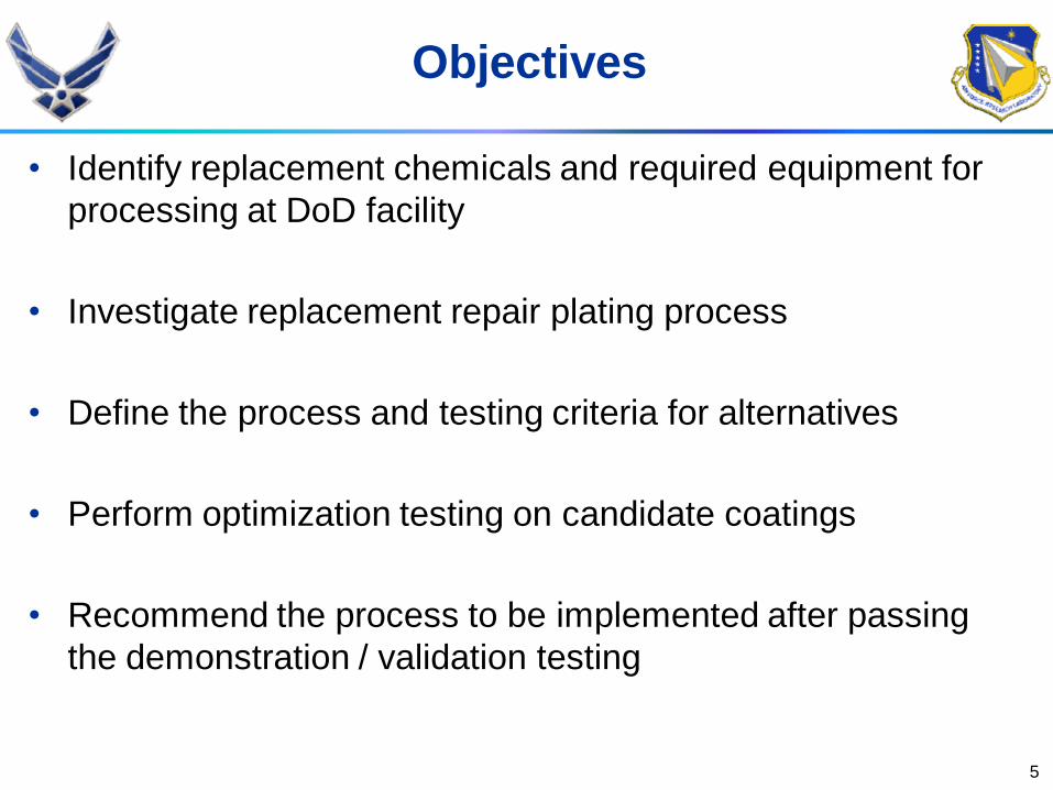
Objectives
• Identify replacement chemicals and required equipment for
processing at DoD facility
• Investigate replacement repair plating process
• Define the process and testing criteria for alternatives
• Perform optimization testing on candidate coatings
• Recommend the process to be implemented after passing
the demonstration / validation testing
5

6
Example Brush Plating Set-up
Test Panel
Plating Solution
Rectifier
Anode Plating Solution Pretreatment, after acetone
wipe, via abrasive “green" water-wet scour
pad mounted on sander
Cathode

• Meet SAE-AMS-QQ-P-416, Type I Class 2 Specification
– No chromate conversion coating
– 0.3 to 0.5 mils coating thickness
• Process the part coating within the repair production period
• Be compatible with DoD facility and worker capability
• Preserve the dimensional tolerance for the mating parts
• Sacrificially protect mild steel from corrosion
• Comparable or lower electrical resistivity than Cd during the service life
• Negligible change in volume between as-plated and end of service life
(similar to Cd).
7
Processing & Performance
Replacement Requirements

1. Aluminum
2. Cadmium-titanium
3. Zinc
4. Lead
5. Zinc-cadmium
6. Nickel
7. Zinc-nickel
8. Nickel-cadmium
9. Tin
10. Tin-cadmium
11. Tin-nickel
12. Tin-zinc
13. Acrylic
14. Epoxy
15. Fluorocarbons
16. Nylon
17. Polyester
18. Polyurethane
8
Eliminate Cd, Pb (and Nickel [Ni]?)
Alternative (Alts)

9
Alternative Notes
1. Aluminum Sacrifices to protect steel, converting to
an alumina, which is an electrical insulator
2. Zinc Also sacrificial to protect mild steel from
corrosion; zinc oxide is 10X to 100X more
electrically insulating than cadmium oxide
3. Tin Plated tin is sacrificial to protect mild steel
in seawater, but tin oxide is 10X more
electrically insulating than cadmium oxide
4. Tin-zinc Known to be sacrificial to protect mild
steel, but its oxides’ electrical resistivity is
unknown and needs to be tested
Remaining Alts. per QQ-P-416
10
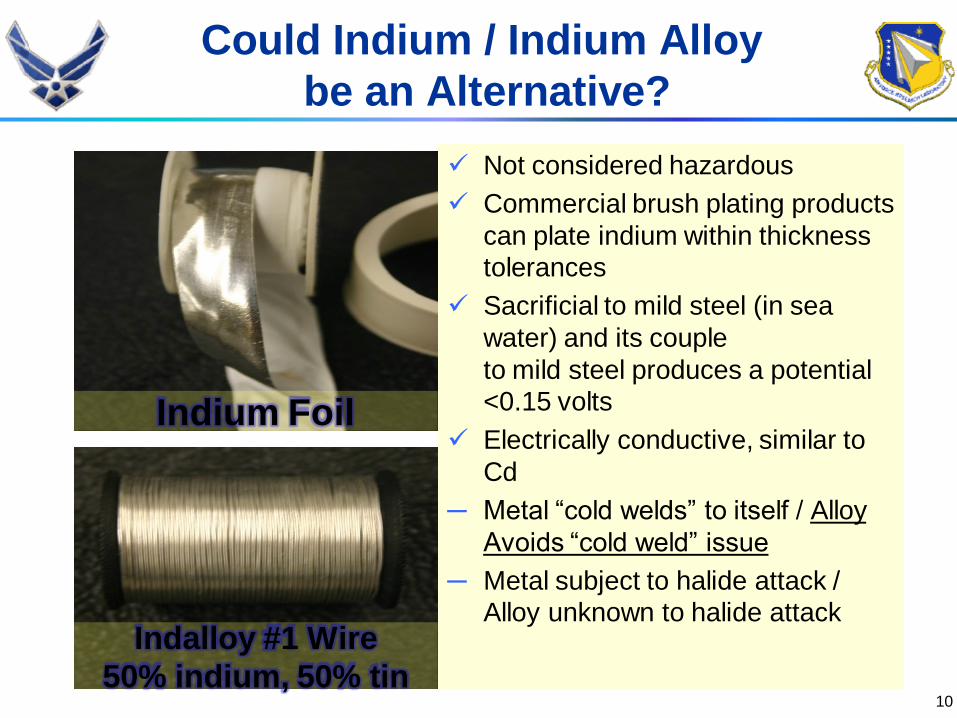
Not considered hazardous
Commercial brush plating products
can plate indium within thickness
tolerances
Sacrificial to mild steel (in sea
water) and its couple
to mild steel produces a potential
<0.15 volts
Electrically conductive, similar to
Cd
─ Metal “cold welds” to itself / Alloy
Avoids “cold weld” issue
─ Metal subject to halide attack /
Alloy unknown to halide attack
Indium Foil
Could Indium / Indium Alloy
be an Alternative?
Indalloy #1 Wire
50% indium, 50% tin

Active (Anodic)
1. Magnesium
2. Manganese
3. Zinc (plated)
4. Aluminum
5. Cadmium (plated)
6. Indium
7. Tin (plated)
8. Steel 1010
9. Iron (cast)
10. Copper (plated)
11. Nickel (plated)
12. Cobalt
13. Bismuth
14. Tungsten
15. Titanium
16. Silver
17. Gold
18. Graphite
Noble (Less Anodic)
11
Indium in a Galvanic Series
12
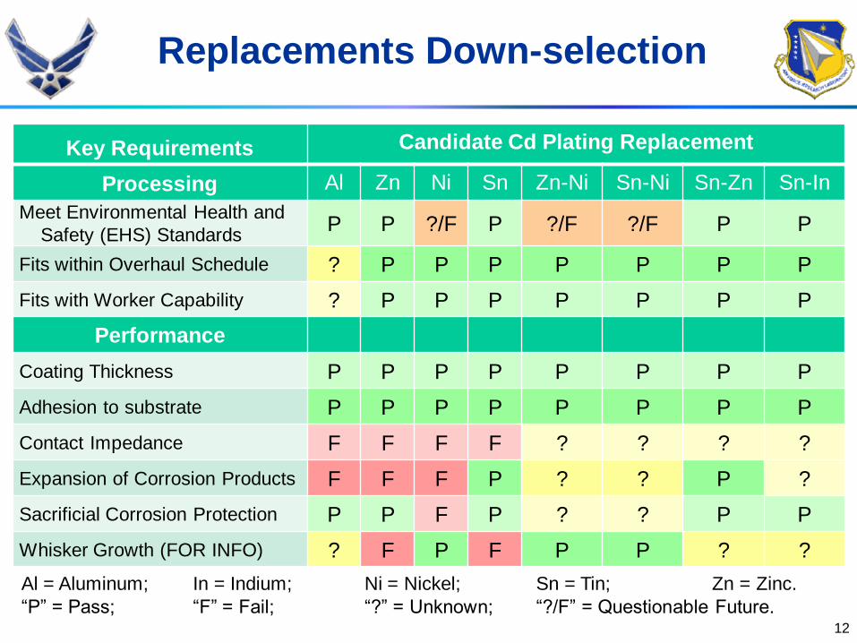
Replacements Down-selection
Key Requirements Candidate Cd Plating Replacement
Processing Al Zn Ni Sn Zn-Ni Sn-Ni Sn-Zn Sn-In
Meet Environmental Health and
Safety (EHS) StandardsP P ?/F P ?/F ?/F P P
Fits within Overhaul Schedule ? P P P P P P P
Fits with Worker Capability ? P P P P P P P
Performance
Coating Thickness P P P P P P P P
Adhesion to substrate P P P P P P P P
Contact Impedance F F F F ? ? ? ?
Expansion of Corrosion Products F F F P ? ? P ?
Sacrificial Corrosion Protection P P F P ? ? P P
Whisker Growth (FOR INFO) ? F P F P P ? ?
Al = Aluminum; In = Indium; Ni = Nickel; Sn = Tin; Zn = Zinc.
“P” = Pass; “F” = Fail; “?” = Unknown; “?/F” = Questionable Future.
13
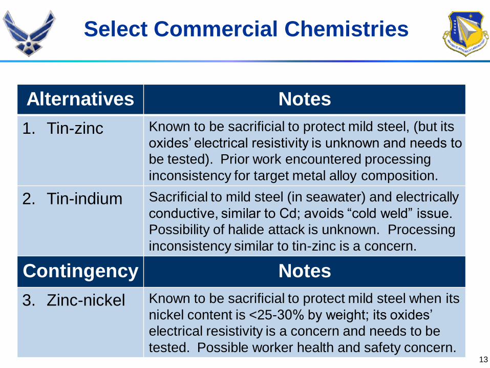
Select Commercial Chemistries
Alternatives Notes
1. Tin-zinc Known to be sacrificial to protect mild steel, (but its
oxides’ electrical resistivity is unknown and needs to
be tested). Prior work encountered processing
inconsistency for target metal alloy composition.
2. Tin-indium Sacrificial to mild steel (in seawater) and electrically
conductive, similar to Cd; avoids “cold weld” issue.
Possibility of halide attack is unknown. Processing
inconsistency similar to tin-zinc is a concern.
Contingency Notes
3. Zinc-nickel Known to be sacrificial to protect mild steel when its
nickel content is <25-30% by weight; its oxides’
electrical resistivity is a concern and needs to be
tested. Possible worker health and safety concern.

14
Alts. Chosen for Testing
Coating
Round 1Composition
(nominal)
Coating
Round 2
Composition
(nominal)
Cd 100% Cd 100% Cd
Sn-Zn @ 7 volts(1) 90% Sn, 10% Zn
Sn-Zn @ 12 volts
(2)70% Sn, 30% Zn
Sn-Zn @ 12
volts (2)70% Sn, 30% Zn
Sn-In (1) 80% Sn, 20% In
Sn-In (2) 90% Sn, 10% In
In-Sn (3) 65% In, 35% Sn In-Sn 70% In, 30% Sn
Zn-Ni (dip plated) 82% Zn, 18% NiZn-Ni (brush
plated)85% Zn, 15% Ni

16
Electrical Resistance
To 4-Wire
Low Contact
Resistance Meter
Panel
Upper Electrode
(1-inch2 Area)
Lower Electrode
(= Panel Area)
Load (200-
pounds/inch2)
Electrical Isolation (plywood)
Electrical
Isolation
(Kapton® Tape)

Electrical Resistance Results,
Round 1
17

Electrical Resistance,
Round 2, Aged Panels
0.0001
0.0010
0.0100
0.1000
1.0000
1,000 10,000 100,000 1,000,000
Imp
ed
an
ce (O
hm
)
Frequency (Hz)
Specification
Aged In-Sn
Aged Cd
In-Sn before Aging
Cd before Aging
Sn-Zn (12V) before Aging
18

Temperature Cycling
Table 6. Temperature Cycling Conditions for Each Test Cycle
Step Number
Temperature Condition
Temperature Range (°F)
Time (minute)
1 Cold -70 to -65 120
2 Ambient +72 to +87 5
3 Hot +175 to +178 120
4 Ambient +87 to +72 5
Figure 1. Variation of Temperature with Time for Temperature Cycling Test
-100
-50
0
50
100
150
2001
0:2
5:3
51
1:0
3:3
61
1:4
2:3
71
2:2
1:3
81
2:5
8:4
01
3:3
7:4
61
4:1
7:2
01
4:5
5:2
11
5:3
3:2
21
6:1
2:2
31
6:5
1:2
41
7:2
8:2
51
8:0
7:2
61
8:4
6:2
71
9:2
3:2
82
0:0
2:3
02
0:4
1:3
12
1:2
0:3
22
1:5
7:3
32
2:3
6:3
42
3:1
5:3
52
3:5
2:3
70
:31
:38
1:1
0:3
91
:49
:40
2:2
6:4
13
:05
:41
3:4
4:4
24
:21
:43
5:0
0:4
45
:39
:45
6:1
7:4
66
:55
:48
7:3
4:4
98
:13
:56
Te
mp
era
ture
( F
)
Time (hour:minute:second)
19

Electrical Resistance,
Round 2, Temperature Cycling
0.0001
0.0010
0.0100
0.1000
1.0000
1,000 10,000 100,000 1,000,000
Imp
ed
an
ce (O
hm
)
Frequency (Hz)
Specification
In-Sn after Temperature Cycling
Cd after Temperature Cycling
In-Sn before Temperature Cycling
Cd before Temperature Cycling
Sn-Zn (12V) before Temperature Cycling
20

Whisker Growth
21
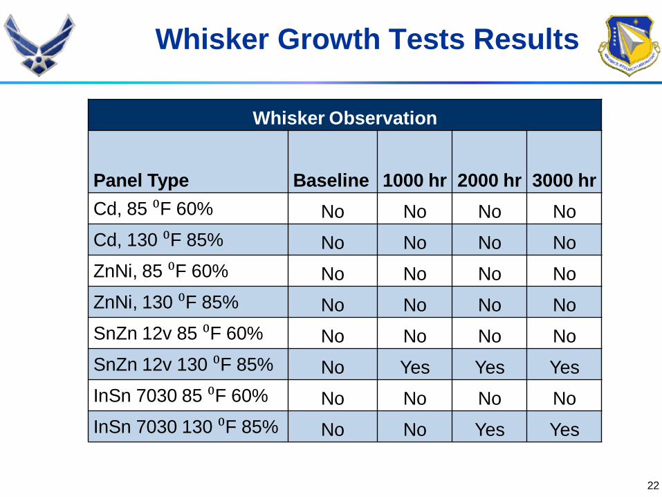
Whisker Growth Tests Results
Whisker Observation
Panel Type Baseline 1000 hr 2000 hr 3000 hr
Cd, 85 ⁰F 60% No No No No
Cd, 130 ⁰F 85% No No No No
ZnNi, 85 ⁰F 60% No No No No
ZnNi, 130 ⁰F 85% No No No No
SnZn 12v 85 ⁰F 60% No No No No
SnZn 12v 130 ⁰F 85% No Yes Yes Yes
InSn 7030 85 ⁰F 60% No No No No
InSn 7030 130 ⁰F 85% No No Yes Yes
22

• Testing per ASTM B 117
– 6 panels per coating
• 4 x 6 panels
• Both scribed and unscribed
panels evaluated
• Testing Results
– Cd – 3000 hrs, scribed and unscribed
– SnZn – 24 hrs, scribed and unscribed
– InSn – unscribed, 192 hours
– ZniNi – did not pass bend adhesion
and did not proceed to this test
Corrosion Resistance
SnZn, 24 hrs exposure
Red Rust
Subtask 067 Task 3 Update & Round 2 Test Results – 18 August 2009 23

Corrosion Chart
TestCd
Coatalyte #312
Sn-Zn
12 V
LDC-5030
In-Sn
LDC
4901/5001
Unscribed2 3 (0.61 ± 0.06) 0 (0.53 ± 0.02) 1 (0.37 ± 0.02)
Electrochemical Properties (ASTM
G 3)OCP (V) -0.78 NSS9 -0.69
Via EIS Method 1Corr Rate
(mpy)32.3 ± 29.3 5.4 ± 6.6 1.3 ± 0.02
Via EIS Method 2Corr Rate
(mpy)32.1 ± 28.7 7.0 ± 7.0 1.5 ± 0.01
Via cathodic polarization (neutral
buffer)
Corr Rate
(mpy)2.5 ± 0.07 69 ± 71 0.52 ± 0.11
Via Tafel measurements of
cathodic polarization (DHS)
Corr Rate
(mpy)4.0 ± 3.8 0.31 ± 0.24
Via Tafel measurements of anodic
polarization (DHS)
Corr Rate
(mpy)73 ± 104 0.60 ± 0.18
Pitting Number None None None
Crevice Corrosion Level Mostly Severe Mostly Severe None to Moderate
24

Subtask 067 Task 3 Update & Round 2 Test Results – 18 August 2009
Multiplex 16 Samples
Test Cell
for Samples
Samples
vacuum
storage
Test Cells
per Samples
Open Circuit Potential Preliminary Results
In-Sn coatings immersion
exposure to the neutral
solution of Na2SO4 + H3BO3
Thermocouples
Electrochemical Properties (Open Circuit Potential)
25

• Mission Essential Need to replacement Cadmium coating on DoD
weapon system with “greener” / safer alternative(s)
• Replacement needs to be sacrificial to mild steel, and electrically
conductive throughout its service – this limits the options.
• Round 1 and Round 2 tests are complete
• No candidate peformed as well as the cadmium on the corrosion
resistance tests
• InSn peformed better than the cadmium in the electrical resistance
tests
• Currently looking at other atlernatives.
26
Summary

Back Up Slides
27

Background
• Cd has been a good coating for this weapon system.
– Some of the mild steel component mating surfaces are
electroplated with Cd
– Prevent corrosion
• Sacrificial to prevent formation of oxides of mild steel
• Galvanic couple with aluminum alloys and stainless steel
– Ensure a high electrical conductivity and sufficient grounding
path during its service life
– Provide the ability to withstand harsh weapon system
environments
• Cd coating / repair process by brush plating that
references SAE-AMS-QQ-P-416
28
29
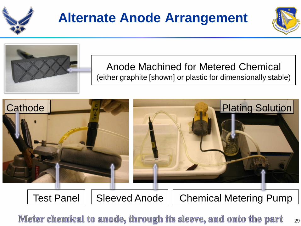
Alternate Anode Arrangement
Test Panel
Cathode
Sleeved Anode
Anode Machined for Metered Chemical (either graphite [shown] or plastic for dimensionally stable)
Chemical Metering Pump
Plating Solution

Procedure:
1. Remove soils/corrosion from plated surfaces
2. Activate the substrate and undamaged Cd
3. Brush plate Cd onto the activated areas:
Wrap sacrificial Cd anode in an absorbent sleeve
Keep the anode sleeve wet with plating solution
Apply a steady, uniform anode motion on the part
Use a constant voltage until the target ampere-
hour is reached
4. Inspect the Cd plating quality30
Cd Spot Repair (Brush) Plating

1. Aluminum
2. Cadmium-titanium
3. Zinc
4. Lead
5. Zinc-cadmium
6. Nickel
7. Zinc-nickel
8. Nickel-cadmium
9. Tin
10. Tin-cadmium
11. Tin-nickel
12. Tin-zinc
13. Acrylic
14. Epoxy
15. Fluorocarbons
16. Nylon
17. Polyester
18. Polyurethane
31
Alternatives (Alts.) per QQ-P-416

32
1. Low temperature eutectic:
• The tin-indium system eutectic is 244°F at ~48.3
weight % tin
• The cadmium-indium-tin system eutectic is ~199°F
• Good for a solder
2. Greater hardness than both Cd and indium:
• Less deformable on the mating surfaces
• Potentially reduces the contact between these
surfaces and electrical conduction
3. Relatively expensive; therefore, conduct a review of
its cost/benefit to adopt indium alloy plating
Caveats of Indium Alloys

33
Convert the anode to
platinum wire instead
of graphite
Feed the plating
solution through the
anode to cool it
• Use a soft anode sleeve
material Indium alloy plating
• Start at 6 volts, adjust for target current density
Nominal average of 2.5 amperes/square inch
• Manage the process resistive heat, which raises the
temperature of the anode and a thin panel
Use a thicker, ⅛- to ¼-inch thick panel
Indium Alloy Brush Plating