cd52 bandit user manual atex iecex 24 jul 2017 bandit user manual_atex...procedures stated in this...
TRANSCRIPT

1801 North Juniper AvenueBroken Arrow, Oklahoma 74012 U.S.A.+1 (918) 258–6068 worldwide
CD52 BanditNon-Intrusive Pig Passage Signaler(ATEX-IECEx Certification)
USER GUIDE

CD52 Bandit (ATEX-IECEx Certification) User Guide
Page 2 of 48
Information in this document is subject to change without notice and applies only to the version of software, hardware, or firmware described on the title page.
The software, hardware, and firmware described in this document are designed, manufactured and written by CDI. The software and firmware © 1999–2010 CDI with all rights reserved. The CD52 product is covered under United States Patent No. 6,489,771 B1 The TRAXALL family of transmitters is covered under United StatesPatent No. 9172406.
This document © 1999, 2017 CDI. All rights reserved.Document Number 89-03-0066-00 Revision 24 July 2017
TAG FOR CD52 BANDIT 81-05-0080 (STANDARD)

CD52 Bandit (ATEX-IECEx Certification) User Guide
Page 3 of 48
WARNING
Any operation involving work on pipelines containing gases or liquids under pressure is potentially hazardous. It is necessary, therefore, to follow correct procedures in the use of this equipment to maintain a safe working environment. No person should use this equipment unless fully aware of potential hazards of working with pressurized pipelines and trained in the procedures stated in this manual.
The purchaser of this equipment is responsible for the training and competence of operators and the manner in which it is used.
Contact CDI immediately should any difficulty arise in the use of this equipment.
WARNING
Always use caution when opening any CDI transmitter that has been in a pressurized environment.
It is possible for pressurized liquid or gas to leak into a transmitter and remain there even after the transmitter has been removed from the pipeline.
Always point the transmitter away from yourself or others when opening a cover or end cap.
WARNING
Field repair of flamepath-related components of these units is not authorized

CD52 Bandit (ATEX-IECEx Certification) User Guide
Page 4 of 48

CD52 Bandit (ATEX-IECEx Certification) User Guide
Page 5 of 48
CONTENTS
INTRODUCTION ..................................................................................6
SETUP & OPERATION ..........................................................................7 Power Options ....................................................................................7 Power Configuration Chart .................................................................8 Battery Installation .............................................................................9 User Board Jumper Settings .............................................................10 24 VDC & SCADA Connections ..........................................................12 Detection Methods ...........................................................................16 User Interface ...................................................................................19
INSTALLATION ...................................................................................28 Standard and Stainless Steel Units ...................................................28 Armored Flex Cable Units .................................................................32
OPTIONAL EQUIPMENT ...................................................................33 Remote Indicator System (RIS) .........................................................33 Cathodic Protection Base Mounting ................................................33 Heater ...............................................................................................33 Heat Risers ........................................................................................33 LineStat .............................................................................................34 Sunshade ..........................................................................................34 WARRANTY ........................................................................................35
SERVICE & MAINTENANCE ...............................................................36
GENERAL ARRANGEMENT DRAWINGS ...........................................37
SYSTEM SPECIFICATIONS .................................................................45
PIG MAGNET MOUNTING ................................................................47
ABOUT CDI ........................................................................................48

CD52 Bandit (ATEX-IECEx Certification) User Guide
Page 6 of 48
INTRODUCTION
*Contact CDI for customer-specified length**CD52 Portable models are battery powered only and have no junction ***Optional configuration for SCADA network communication (see next page)
INTRODUCTION
The CD52 Bandit is a computerized electronic device for non-intrusive detection of pipeline pigs equipped with either a permanent magnet or 22 Hz electromagnetic transmitter.
The Bandit accomplishes this by a proprietary and patented magnetic field antenna array located in its base and attached to (or near) the pipeline. This antenna array signals an on-board computer if and when a pig passage has occurred.
When a pig passage is detected, the time and date of passage are recorded into the on-board memory of the Bandit and displayed on an LCD screen.
In addition to the most recent pig passage time and date, the Bandit remembers the dates and times of the previous nine pig passages as well. An operator may quickly and easily retrieve the dates and times of the 10 most recent pig passages via the Bandit’s user interface. The CD52 Bandit is available in several configurations:
• Rigid stalk extension-mounted (“standard”) • Extended flex-cable* • Extended pipe* • Portable** • Stainless steel enclosed, flex-cable, extended-pipe, and portable • 4-20mA Current Loop Interface***
24 VDC,SCADA JUNCTION,& 4-20mA OUTPUT
COMPUTER & DISPLAY
BASE & ANTENNA
STANDARD

CD52 Bandit (ATEX-IECEx Certification) User Guide
Page 7 of 48
SETUP & OPERATION
SETUP & OPERATION
Power Options
The Bandit in its standard configuration can be powered for one year on two new D-Cell alkaline batteries (see notes). However, many customers choose to power the Bandit by supplying 24 VDC power.
In extreme cold temperatures, 24 VDC will be necessary to power the Bandit as a small heating element option (see pg. 33) is required. Also, ATEX/IECEx guidelines require use of external 24 VDC power where temperatures exceed +45°C.
See the Power Configuration chart on the following page to determine which power option is required for your conditions.
WARNING:Always remove batteries before placing the unit into storage
and/or configuring for 24 VDC operation. Failure to do so may result in damage and may void warranty.
NOTE: If using batteries as a power source, DURACELL® PROCELL (PC1300) D-Cell
alkaline batteries are required by ATEX and/or IECEx standards to maintain system certification.
NOTE: Bandits with optional 4-20mA Current Loop Interface configuration require 24 VDC power.
They cannot be powered by batteries.
EXTENDED PIPE
FLEX CABLE FLEX CABLEw/STAINLESS
BASE
ENCLOSEDw/EXTENDED PIPE
PORTABLE
316 STAINLESS STEEL ENCLOSED
PORTABLEw/STAINLESS
BASE
ENCLOSED w/FLEX CABLE

CD52 Bandit (ATEX-IECEx Certification) User Guide
Page 8 of 48
SETUP & OPERATION
Pow
er C
onfig
urati
on
Gree
n in
dica
tes A
TEX–
IECE
x ce
rtifie
d te
mpe
ratu
re ra
nge

CD52 Bandit (ATEX-IECEx Certification) User Guide
Page 9 of 48
SETUP & OPERATION
Battery Installation
To install D-cell batteries:
1. Unscrew and carefully remove front cover
2. If old batteries are in place, pull cable-tie release tab (use small screwdriver or fingernail) to disengage cable-tie.
3. Insert new alkaline batteries,both with positive (+) side up.
NOTE: The battery cable ties are releasable. Do not cut them.
CD52 Bandit (ATEX-IECEx Certification) User Guide
Page 10 of 48
SETUP & OPERATION
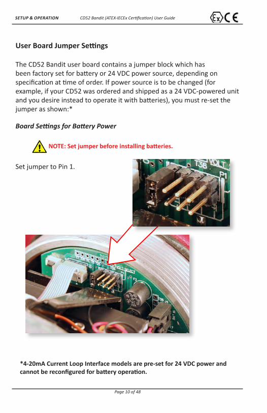
User Board Jumper Settings
The CD52 Bandit user board contains a jumper block which has been factory set for battery or 24 VDC power source, depending on specification at time of order. If power source is to be changed (for example, if your CD52 was ordered and shipped as a 24 VDC-powered unit and you desire instead to operate it with batteries), you must re-set the jumper as shown:* Board Settings for Battery Power
Set jumper to Pin 1.
NOTE: Set jumper before installing batteries.
*4-20mA Current Loop Interface models are pre-set for 24 VDC power and cannot be reconfigured for battery operation.
CD52 Bandit (ATEX-IECEx Certification) User Guide
Page 11 of 48
SETUP & OPERATION
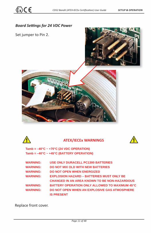
Board Settings for 24 VDC Power
Set jumper to Pin 2.
ATEX/IECEx WARNINGS
Tamb = –40°C ~ +70°C (24 VDC OPERATION)Tamb = –40°C ~ +45°C (BATTERY OPERATION)
WARNING: USE ONLY DURACELL PC1300 BATTERIESWARNING: DO NOT MIX OLD WITH NEW BATTERIESWARNING: DO NOT OPEN WHEN ENERGIZEDWARNING: EXPLOSION HAZARD – BATTERIES MUST ONLY BE CHANGED IN AN AREA KNOWN TO BE NON-HAZARDOUSWARNING: BATTERY OPERATION ONLY ALLOWED TO MAXIMUM 45°CWARNING: DO NOT OPEN WHEN AN EXPLOSIVE GAS ATMOSPHERE
IS PRESENT
Replace front cover.

CD52 Bandit (ATEX-IECEx Certification) User Guide
Page 12 of 48
SETUP & OPERATION
24 VDC & SCADA Connections
It is the customer’s responsibility to provide their own wiring and conduit for 24 VDC power and SCADA.* CDI recommends routing 24 VDC and SCADA wiring through separate conduits. To route 24 VDC and SCADA into the Bandit unit:
1. Standard Unit: Remove threaded outlet plug(s) from the Killark junction box as shown.
* SCADA (Supervisory Control and Data Acquisition) compatible standard relay contacts can be used for passage annunciation (lights, horns, etc.) where an unmanned passage must be monitored. SCADA-compatible 4-20mA option allows connection to plant automation equipment using current loop interfacing.
CD52 Bandit (ATEX-IECEx Certification) User Guide
Page 13 of 48
SETUP & OPERATION
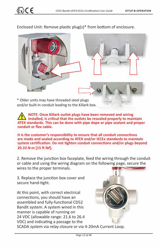
Enclosed Unit: Remove plastic plug(s)* from bottom of enclosure.
* Older units may have threaded steel plugs and/or built-in conduit leading to the Killark box.
2. Remove the junction box faceplate, feed the wiring through the conduit or cable and using the wiring diagram on the following page, secure the wires to the proper terminals.
3. Replace the junction box cover and secure hand-tight.
At this point, with correct electrical connections, you should have an assembled and fully-functional CD52 Bandit system. A system wired in this manner is capable of running on 24 VDC (allowable range: 21.6 to 26.4 VDC) and indicating a passage to the SCADA system via relay closure or via 4-20mA Current Loop.
NOTE: Once Killark outlet plugs have been removed and wiring installed, is critical that the outlets be resealed properly to maintain
ATEX standards. This can be done with pipe dope or pipe sealant and proper conduit or flex cable.
It is the customer’s responsibility to ensure that all conduit connections are made and sealed according to ATEX and/or IECEx standards to maintain system certification. Do not tighten conduit connections and/or plugs beyond 20.33 N·m [15 ft lbf].

CD52 Bandit (ATEX-IECEx Certification) User Guide
Page 14 of 48
SETUP & OPERATION
FOR
BA
TTE
RY
OP
ER
ATI
ON
,P
LAC
E J
UM
PE
RH
ER
E
FOR
24V
OP
ER
ATI
ON
,P
LAC
E J
UM
PE
R H
ER
E
P1
DET
AIL
'A'
OFF
+5
+3.3
BATT
It is
the
resp
onsi
bilit
y of
the
cust
omer
tom
ake
thes
e co
nnec
tions
pro
perly
wha
teve
rpi
pe o
r con
duit
is c
hose
n fo
r the
job.
1. R
emov
e a
plug
in th
e si
de o
f the
out
let b
ody
for
ins
ertio
n of
cus
tom
er w
iring
.2.
Rem
ove
the
lid o
f the
out
let b
ody.
3. I
nsta
ll th
e cu
stom
er p
rovi
ded
cond
uit a
nd w
iring
.
F
or w
iring
, stri
p of
f wire
insu
latio
n to
exp
ose
5/16
" len
gth
of w
ire.
Inse
rt a
smal
l dia
met
er s
crew
driv
er (o
r sim
ilar t
ool)
into
a s
quar
e
o
peni
ng a
nd d
epre
ss th
e ta
b. T
his
will
ope
n th
e ad
jace
nt ro
und
term
inal
. Ins
ert t
he e
xpos
ed w
ire in
to th
e te
rmin
al u
ntil
it st
ops,
then
rem
ove
the
tool
from
the
squa
re o
peni
ng to
sec
ure
the
wire
.4.
Rea
ssem
ble
the
lid w
ith th
e ou
tlet b
ody.
ATE
X B
AN
DIT
WIR
ING
/IN
STA
LLA
TIO
N IN
STR
UC
TIO
NS
5. O
pen
Ban
dit e
nclo
sure
and
mov
e ju
mpe
r on
PC
B a
s
s
how
n in
Det
ail '
A'.
6. R
epla
ce B
andi
t enc
losu
re.
If 24
V C
onne
ctio
ns w
ere
used
,co
mpl
ete
step
s 5
& 6
BLA
CK
WIR
E
BR
OW
N W
IRE
RE
D W
IRE
YE
LLO
W W
IRE
WH
ITE
WIR
E
CO
MM
ON
NO
RM
ALL
Y O
PE
NN
OR
MA
LLY
CLO
SE
DIN
STA
LL S
ITE
PO
WE
R +
24V
DC
INS
TALL
SIT
E P
OW
ER
0V
DCC
DI U
SE
ON
LY
CU
STO
MER
CO
NN
ECTI
ON
S(D
O N
OT
CO
NN
ECT
CO
MM
ON
TO 0
VDC
TER
MIN
ALS
)
CD
I CO
NN
ECTI
ON
S
OU
TLET
BO
DY
SHO
WN
WIT
H C
OVE
R R
EMO
VED
24V
VOLT
AG
E R
EQU
IREM
ENTS
21.6
VD
C M
INIM
UM
26.4
VD
C M
AX
IMU
MM
EA
SU
RE
D A
T C
D52
TE
RM
INA
L B
LOC
K
STA
ND
AR
D: 0
.48
WA
TTS
HE
ATE
R O
PTI
ON
: 12
WA
TTS
INTE
RM
ITTE
NT
RIS
OP
TIO
N: 8
.4 W
ATT
S
POW
ER R
EQU
IREM
ENTS
RE
VIS
ION
SR
EV
.D
ES
CR
IPTI
ON
DA
TEA
PP
RO
VE
DA
RE
LEA
SE
D6/
26/2
012
DS
BR
EV
ISE
D P
ER
EC
R 1
1251
301;
RE
PLA
CE
D
OU
TLE
T B
OD
Y; R
EV
ISE
D N
OTE
S &
TIT
LE
TO IN
CLU
DE
ALL
ATE
X B
AN
DIT
S1/
23/2
014
DS
D C B AABCD
12
34
56
788
76
54
32
1
THE
INFO
RMA
TION
CO
NTA
INED
IN T
HIS
DRA
WIN
G IS
THE
SO
LE P
ROPE
RTY
OF
CD
I. A
NY
REPR
OD
UCTIO
N IN
PA
RT O
RA
S A
WHO
LE W
ITHO
UT T
HE W
RITT
ENPE
RMIS
SIO
N O
F C
DI I
S PR
OHI
BITE
D.
PRO
PRIE
TARY
AN
D C
ON
FIDE
NTIA
L
NEX
T A
SSY
USED
ON
APP
LICA
TION
DIM
ENSI
ON
S A
RE IN
INC
HES
TOLE
RAN
CES
:FR
AC
TION
AL
1/3
2A
NG
ULA
R:
2TW
O P
LAC
E D
ECIM
AL
.03
THRE
E PL
AC
E D
ECIM
AL
.010
MA
TERI
AL
FIN
ISH
DRA
WN
CHE
CKE
D
ENG
APP
R.
MFG
APP
R.
Q.A
.
CO
MM
ENTS
:
DA
TEN
AM
E
TITLE
:
SIZE B
DW
G.
NO
.RE
V
WEI
GHT
: SC
ALE
:
UNLE
SS O
THER
WIS
E SP
ECIF
IED
:
B
WIR
ING
INST
RU
CTI
ON
S,C
D52
ATE
X B
AN
DIT
SHEE
T 1 O
F 1
89-0
3-00
62-0
0D
O N
OT
SCA
LE D
RAW
ING
INTE
RPRE
T G
EOM
ETRI
CTO
LERA
NC
ING
PER
:
ASM
E Y1
4.5M
- 19
94
DS
9/23
/200
8
ECN
#:
CD52 Bandit (ATEX-IECEx Certification) User Guide
Page 15 of 48
SETUP & OPERATION
It is
the
resp
onsi
bilit
y of
the
cust
omer
tom
ake
thes
e co
nnec
tions
pro
perly
wha
teve
rpi
pe o
r con
duit
is c
hose
n fo
r the
job.
1. R
emov
e a
plug
in th
e si
de o
f the
out
let b
ody
for
ins
ertio
n of
cus
tom
er w
iring
.2.
Rem
ove
the
lid o
f the
out
let b
ody.
3. I
nsta
ll th
e cu
stom
er p
rovi
ded
cond
uit a
nd w
iring
.
F
or w
iring
, stri
p of
f wire
insu
latio
n to
exp
ose
5/16
" len
gth
of w
ire.
Inse
rt a
smal
l dia
met
er s
crew
driv
er (o
r sim
ilar t
ool)
into
a s
quar
e
o
peni
ng a
nd d
epre
ss th
e ta
b. T
his
will
open
the
adja
cent
roun
d
te
rmin
al. I
nser
t the
exp
osed
wire
into
the
term
inal
unt
il it
stop
s,
th
en re
mov
e th
e to
ol fr
om th
e sq
uare
ope
ning
to s
ecur
e th
e w
ire.
4. R
eass
embl
e th
e lid
with
the
outle
t bod
y.
ATE
X B
AN
DIT
WIR
ING
/IN
STA
LLA
TIO
N IN
STR
UC
TIO
NS
BLAC
K W
IRE
BRO
WN
WIR
ER
ED W
IRE
YELL
OW
WIR
EW
HIT
E W
IRE
NO
T U
SED
-ve
(4-2
0mA
LOO
P IN
PUT)
+ve
(4-2
0mA
LOO
P IN
PUT)
INST
ALL
SITE
PO
WER
+24
VDC
INST
ALL
SITE
PO
WER
0VD
C
CD
I USE
ON
LY
23
45
67
89
10
TER
MIN
AL N
UM
BER
S
CU
STO
MER
CO
NN
ECTI
ON
SM
AXIM
UM
WIR
E SI
ZE: D
iam
eter
= 1
.78m
m,
Cro
ss-S
ectio
n Ar
ea =
2.5
mm
²(D
O N
OT
CO
NN
ECT
CO
MM
ON
TO 0
VDC
TER
MIN
ALS
)
CD
I CO
NN
ECTI
ON
S
OU
TLET
BO
DY
SHO
WN
WIT
H C
OVE
R R
EMO
VED
24V
VOLT
AG
E R
EQU
IREM
ENTS
21.6
VD
C M
INIM
UM
26.4
VD
C M
AXIM
UM
MEA
SUR
ED A
T C
D52
TER
MIN
AL B
LOC
K
STAN
DAR
D W
ITH
4-2
0mA
OPT
ION
: 1.6
WAT
TSH
EATE
R O
PTIO
N: 1
2 W
ATTS
INTE
RM
ITTE
NT
RIS
OPT
ION
: 8.4
WAT
TS
POW
ER R
EQU
IREM
ENTS
1
NO
TES:
1. W
HEN
PIG
IS N
OT
DET
ECTE
D, O
UTP
UT
SHAL
L BE
4m
A.2.
WH
EN P
IG IS
DET
ECTE
D, O
UTP
UT
SHAL
L BE
20m
A.3.
BAT
TER
Y O
PER
ATIO
N N
OT
AVAI
LABL
E W
ITH
4-2
0mA
OPT
ION
.
REV
ISIO
NS
REV
.D
ESC
RIP
TIO
ND
ATE
APPR
OVE
DA
REL
EASE
D02
/23/
2017
DS/
NT
D C B AABCD
12
34
56
788
76
54
32
1
THE
INFO
RMA
TION
CO
NTA
INED
IN T
HIS
DRA
WIN
G IS
THE
SO
LE P
ROPE
RTY
OF
CD
I. A
NY
REPR
OD
UCTIO
N IN
PA
RT O
RA
S A
WHO
LE W
ITHO
UT T
HE W
RITT
ENPE
RMIS
SIO
N O
F C
DI I
S PR
OHI
BITE
D.
PRO
PRIE
TARY
AN
D C
ON
FIDE
NTIA
L
NEX
T A
SSY
USED
ON
APP
LICA
TION
DIM
ENSI
ON
S A
RE IN
INC
HES
TOLE
RAN
CES
:FR
AC
TION
AL
1/3
2A
NG
ULA
R:
2TW
O P
LAC
E D
ECIM
AL
.03
THRE
E PL
AC
E D
ECIM
AL
.010
MA
TERI
AL
FIN
ISH
DRA
WN
CHE
CKE
D
ENG
APP
R.
MFG
APP
R.
Q.A
.
CO
MM
ENTS
:
DA
TEN
AM
E
TITLE
:
SIZE B
DW
G.
NO
.RE
V
WEI
GHT
: SC
ALE
: 1:1
UNLE
SS O
THER
WIS
E SP
ECIF
IED
:
ASH
EET 1
OF
1
89-0
3-00
62-0
2D
O N
OT
SCA
LE D
RAW
ING
INTE
RPRE
T G
EOM
ETRI
CTO
LERA
NC
ING
PER
:
ASM
E Y1
4.5M
- 19
94
ECR
#:0
2161
701
2/15
/201
7
WIR
ING
INST
RUC
TION
S,4-
20m
A O
PTIO
N,
CD5
2 A
TEX
BAN
DIT
DS
DS
02/1
5/20
17
DM
02/2
0/20
17
02/2
0/20
17JF JD
02/2
0/20
17
CD52 Bandit (ATEX-IECEx Certification) User Guide
Page 16 of 48
SETUP & OPERATION
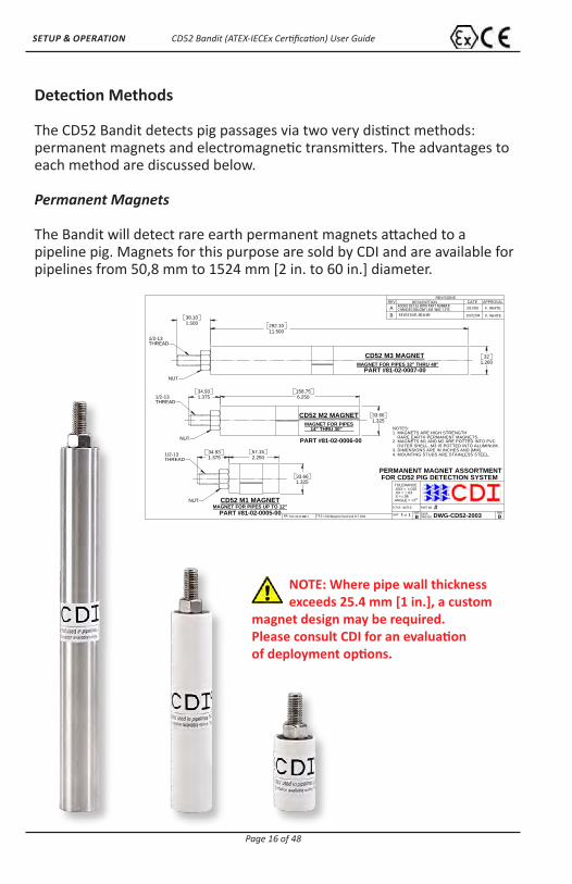
Detection Methods
The CD52 Bandit detects pig passages via two very distinct methods: permanent magnets and electromagnetic transmitters. The advantages to each method are discussed below.
Permanent Magnets
The Bandit will detect rare earth permanent magnets attached to a pipeline pig. Magnets for this purpose are sold by CDI and are available for pipelines from 50,8 mm to 1524 mm [2 in. to 60 in.] diameter.
38.101.500
PART #81-02-0007-00
PART #81-02-0006-00
1.26032
292.1011.500
THREAD
MAGNET FOR PIPES 32" THRU 48"CD52 M3 MAGNET
1/2-13
NUT
of DWG-CD52-20031
FOR CD52 PIG DETECTION SYSTEM
CD52\Magnets\TOP ASSEMBLY B
SCALE:
BSIZE REV
PERMANENT MAGNET ASSORTMENT
DWG NO.SHT
REVISIONSREV DESCRIPTION DATE APPROVAL
ENGR1
PART NO.NOTED
RareEarth SET 2004N/A: FILE:
2
TOLERANCE.XXX = .015.XX = .03.X = .06ANGLE =
#
REVISED M1, M2 & M3
A F. WHITE2/17/00
10/21/04CHANGED DIA DIM 1.345 WAS 1.315
F. WHITE
ADDED DECAL WITH PART NUMBER
B
34.931.375
4. MOUNTING STUDS ARE STAINLESS STEEL.
CD52 M2 MAGNET
6.250158.75
33.661.325
14" THRU 30"MAGNET FOR PIPES
THREAD1/2-13
NOTES:1. MAGNETS ARE HIGH STRENGTH RARE EARTH PERMANENT MAGNETS.2. MAGNETS M1 AND M2 ARE POTTED INTO PVC OUTER SHELL, M3 IS POTTED INTO ALUMINUM.3. DIMENSIONS ARE IN INCHES AND [MM].
NUT
34.931.375
CD52 M1 MAGNET
PART #81-02-0005-00
2.25057.15
33.66
MAGNET FOR PIPES UP TO 12"
1.325
THREAD1/2-13
NUT
NOTE: Where pipe wall thickness exceeds 25.4 mm [1 in.], a custom
magnet design may be required. Please consult CDI for an evaluation of deployment options.

CD52 Bandit (ATEX-IECEx Certification) User Guide
Page 17 of 48
SETUP & OPERATION
Advantages of Permanent Magnets
• Small • Inexpensive • Low maintenance • Batteries are not required
Despite these benefits, because of the permanent magnet’s static magnetic field, it may be difficult to locate a pig that is stalled, obstructed, or otherwise immobilized in a pipeline. In these situations, an active (electromagnetic) transmitter is a recommended option.
Electromagnetic Transmitters
The CD52 Bandit detects active electromagnetic transmitters. CDI offers the largest family of pipeline pig location and tracking transmitters in the industry.
Our Transmitters operate by emitting electromagnetic fields at a very low frequency (between 15 and 30 Hz). This makes CDI’s pig tracking transmitters safe and reliable for use in any onshore or offshore environment and any pipeline product (water, oil, gas, ammonia, carbon dioxide, etc.).
Many models even have the ability to remain dormant until activated by preconfigured pipeline pressure.
CDI T-Series 22 Hz Electromagnetic Transmitters

CD52 Bandit (ATEX-IECEx Certification) User Guide
Page 18 of 48
SETUP & OPERATION
Another advantage of CDI’s active transmitters is the ease of locating an immobilized pig. A stuck pig can easily be detected by walking the pipeline from the last known location using a handheld active locater system. With that in mind, CDI is proud to offer our customers the TRAXALL Multi-source Pig Location and Tracking System.
TRAXALL receivers are ideal for tracking, locating, and pinpointing CDI X-Series electromagnetic transmitters, pigging industry-
standard 22 Hz “Legacy” transmitters, and magnetic-
flux leakage (MFL) pigs.
It is possible to use both a permanent magnet and a transmitter in the same pig. This will not prevent the Bandit, TRAXALL, or CD42 Receiver systems from successfully tracking and locating pigs.
Regardless of which type of transmission source you use, the Bandit will detect it.
Advantages of Electromagnetic Transmitters
• Easily located with a handheld device • Quicker to locate
CDI X-Series Adjustable-frequency Electromagnetic Transmitters
(See your CDI distributor or visit www.pigging.com for more about TRAXALL!)

CD52 Bandit (ATEX-IECEx Certification) User Guide
Page 19 of 48
SETUP & OPERATION
The User Interface
The Bandit’s user interface display contains much information for an operator, yet is quite simple and easy to read.
This display automatically cycles between showing the most recent pig passage time, date and the actual real-time every seven (7) seconds. This allows the operator to approach the Bandit on site and see the most recent pig passage time and verify the internal clock is set correctly – all without touching the unit.
Passage Time / Current Time
These display segments normally alternate between showing the most recent pig passage and the actual real-time as known by the unit. When the real-time is
displayed, the colon will blink (momentarily appear) and the “TIME” Active Function Indicator segment will display.
When the most recent pig passage time is displayed, the colon display will be constant (non-blinking) and the “TIME” Active Function Indicator segment will not display.
Passage Date / Current Date
These segments normally alternate between displaying the real-time date and the date of the most recent pig passage. This date is in American format (MONTH–DATE; the year is
not displayed). Therefore, 4–05 would be April 5th, with the year assumed to be current year.
ACTIVEFUNCTION
INDICATORSPASSAGE DATE/CURRENT DATE
PASSAGEINDICATORMARKED
RECENTPASSAGE
INDICATOR
PASSAGE TIME/CURRENT TIME
ACTIVEFUNCTION
INDICATORSPASSAGE DATE/CURRENT DATE
PASSAGEINDICATORMARKED
RECENTPASSAGE
INDICATOR
PASSAGE TIME/CURRENT TIME
ACTIVEFUNCTION
INDICATORSPASSAGE DATE/CURRENT DATE
PASSAGEINDICATORMARKED
RECENTPASSAGE
INDICATOR
PASSAGE TIME/CURRENT TIME

CD52 Bandit (ATEX-IECEx Certification) User Guide
Page 20 of 48
SETUP & OPERATION
Recent Passage Indicator
The Recent Passage Indicator segment at the lower half of the Bandit’s display area indicates that a pig passage has been recently detected.
The behavior of this segment conveys information about how recently the pig passage occurred.
When a pig passage occurs, the segment will blink once per second for one full hour after the pig passage. After one hour, the display will switch to a constant-on mode. This feature allows an operator to quickly determine how recently a pig has passed.
Therefore, a constant-on segment indicates a pig passage has occurred within the last 12 hours but more than one hour ago.
RECENT PASSAGE SEGMENT STATUS
Displayed Passage Indicator
The Displayed Passage Indicator is a cone-shaped array of 10 segments. Each one of these individual segments represents one of the 10 pig passage times recorded in
the Bandit’s memory. The larger the segment, the more recent the pig passage.
MEANING
SEGMENT NOT LITNo passage detected
within the last 12 hours
SEGMENT BLINKINGPassage was detected
within the last one hour
SEGMENT LIT, NOT BLINKING
Passage was detected more than one hour ago,
but less than 12 hours ago
CD52 Bandit (ATEX-IECEx Certification) User Guide
Page 21 of 48
SETUP & OPERATION
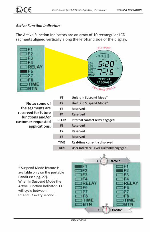
* Suspend Mode feature is available only on the portable Bandit (see pg. 27). When in Suspend Mode the Active Function Indicator LCD will cycle between F1 and F2 every second.
Note: some of the segments are
reserved for future functions and/or
customer-requested applications.
F1 Unit is in Suspend Mode*
F2 Unit is in Suspend Mode*
F3 Reserved
F4 Reserved
RELAY Internal contact relay engaged
F6 Reserved
F7 Reserved
F8 Reserved
TIME Real-time currently displayed
BTN User Interface Lever currently engaged
Active Function Indicators
The Active Function Indicators are an array of 10 rectangular LCD segments aligned vertically along the left-hand side of the display.
CD52 Bandit (ATEX-IECEx Certification) User Guide
Page 22 of 48
SETUP & OPERATION
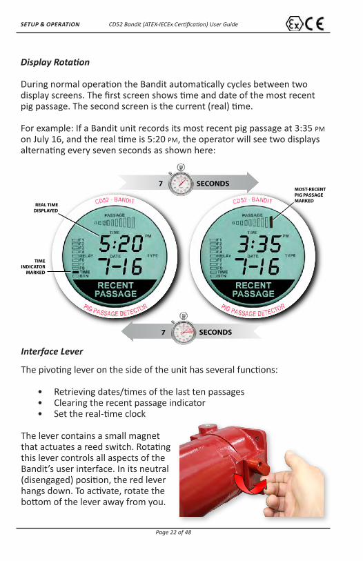
Display Rotation
During normal operation the Bandit automatically cycles between two display screens. The first screen shows time and date of the most recent pig passage. The second screen is the current (real) time.
For example: If a Bandit unit records its most recent pig passage at 3:35 PM on July 16, and the real time is 5:20 PM, the operator will see two displays alternating every seven seconds as shown here:
MOST-RECENTPIG PASSAGEMARKED
REAL TIMEDISPLAYED
SECONDS7
TIMEINDICATOR
MARKED
SECONDS7
Interface Lever
The pivoting lever on the side of the unit has several functions:
• Retrieving dates/times of the last ten passages • Clearing the recent passage indicator • Set the real-time clock
The lever contains a small magnet that actuates a reed switch. Rotating this lever controls all aspects of the Bandit’s user interface. In its neutral (disengaged) position, the red lever hangs down. To activate, rotate the bottom of the lever away from you.

CD52 Bandit (ATEX-IECEx Certification) User Guide
Page 23 of 48
SETUP & OPERATION
Any time the Bandit’s lever is activated, the “BTN” display segment will confirm contact.
To ensure Bandit’s availability under adverse conditions (wind, icing, vandalism, etc.) that could move the lever into the engaged position while unattended, the unit will automatically override the lever setting after one minute and 45 seconds, and automatically return to normal operation.
Real-time Display
The primary purpose of the real-time display is to allow an operator to quickly and easily confirm the clock is set to the correct time. (See pg. 26 for instructions on setting the clock.)
The real-time display has the following characteristics:
NO PASSAGEINDICATORS MARKED
BLINKINGTIME DISPLAY
COLON
TIMEINDICATOR
MARKED
CD52 Bandit (ATEX-IECEx Certification) User Guide
Page 24 of 48
SETUP & OPERATION
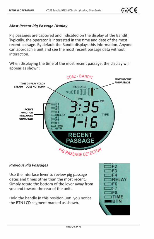
Most Recent Pig Passage Display
Pig passages are captured and indicated on the display of the Bandit. Typically, the operator is interested in the time and date of the most recent passage. By default the Bandit displays this information. Anyone can approach a unit and see the most recent passage data without interaction.
When displaying the time of the most recent passage, the display will appear as shown:
MOST-RECENTPIG PASSAGETIME DISPLAY COLON
STEADY – DOES NOT BLINK
ACTIVEFUNCTION
INDICATORSUNMARKED
Previous Pig Passages
Use the Interface lever to review pig passage dates and times other than the most recent. Simply rotate the bottom of the lever away from you and toward the rear of the unit.
Hold the handle in this position until you notice the BTN LCD segment marked as shown.
CD52 Bandit (ATEX-IECEx Certification) User Guide
Page 25 of 48
SETUP & OPERATION
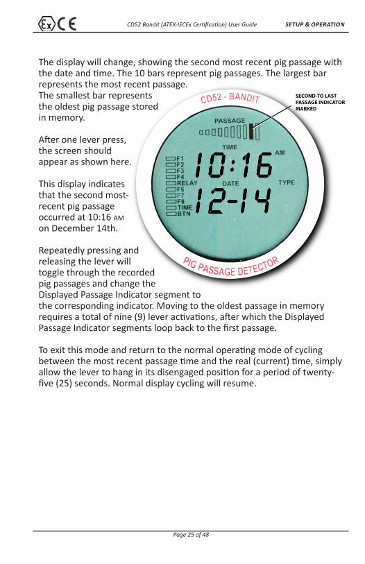
The display will change, showing the second most recent pig passage with the date and time. The 10 bars represent pig passages. The largest bar represents the most recent passage.The smallest bar represents the oldest pig passage stored in memory.
After one lever press, the screen should appear as shown here.
This display indicates that the second most-recent pig passage occurred at 10:16 AM on December 14th.
Repeatedly pressing and releasing the lever will toggle through the recorded pig passages and change the Displayed Passage Indicator segment to the corresponding indicator. Moving to the oldest passage in memory requires a total of nine (9) lever activations, after which the Displayed Passage Indicator segments loop back to the first passage.
To exit this mode and return to the normal operating mode of cycling between the most recent passage time and the real (current) time, simply allow the lever to hang in its disengaged position for a period of twenty-five (25) seconds. Normal display cycling will resume.
SECOND-TO LASTPASSAGE INDICATORMARKED
CD52 Bandit (ATEX-IECEx Certification) User Guide
Page 26 of 48
SETUP & OPERATION
Clearing the “Recent Passage” Flag
The Recent Passage LCD segment will blink for one hour after a pig passage then remain on for an additional 11 hours. However, you may wish
to manually terminate the blinking cycle (for example, when the Bandit is used in a portable application or on a launcher or receiver). To clear the recent passage display, rotate the Interface Lever into the “activated” position (see pg. 22) and hold it there for a period of four (4) seconds. Once cleared, release the lever to return the unit to normal operation.
Removing the “Recent Passage” message from the screen will not affect anything in memory. The most recent pig passage time and date will cycle every few seconds.
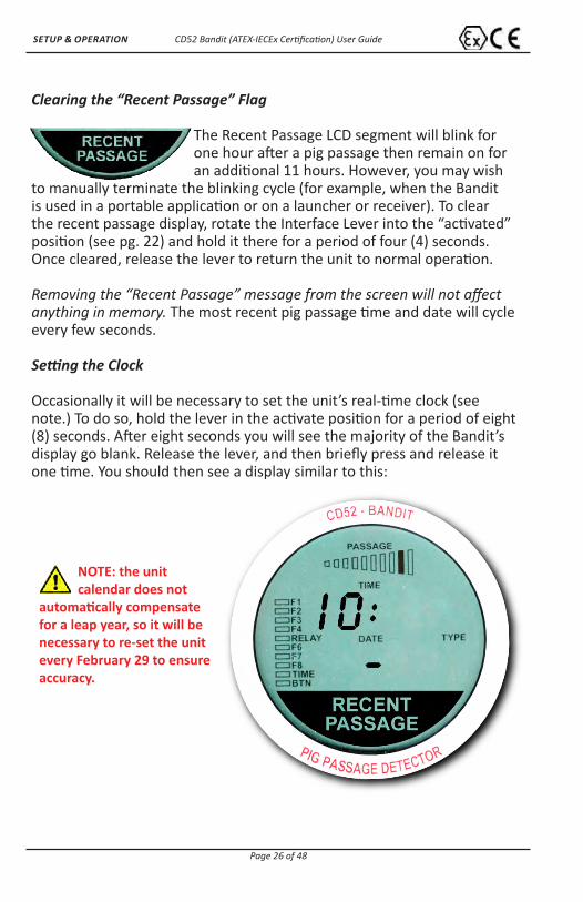
Setting the Clock
Occasionally it will be necessary to set the unit’s real-time clock (see note.) To do so, hold the lever in the activate position for a period of eight (8) seconds. After eight seconds you will see the majority of the Bandit’s display go blank. Release the lever, and then briefly press and release it one time. You should then see a display similar to this:
NOTE: the unit calendar does not
automatically compensate for a leap year, so it will be necessary to re-set the unit every February 29 to ensure accuracy.
CD52 Bandit (ATEX-IECEx Certification) User Guide
Page 27 of 48
SETUP & OPERATION
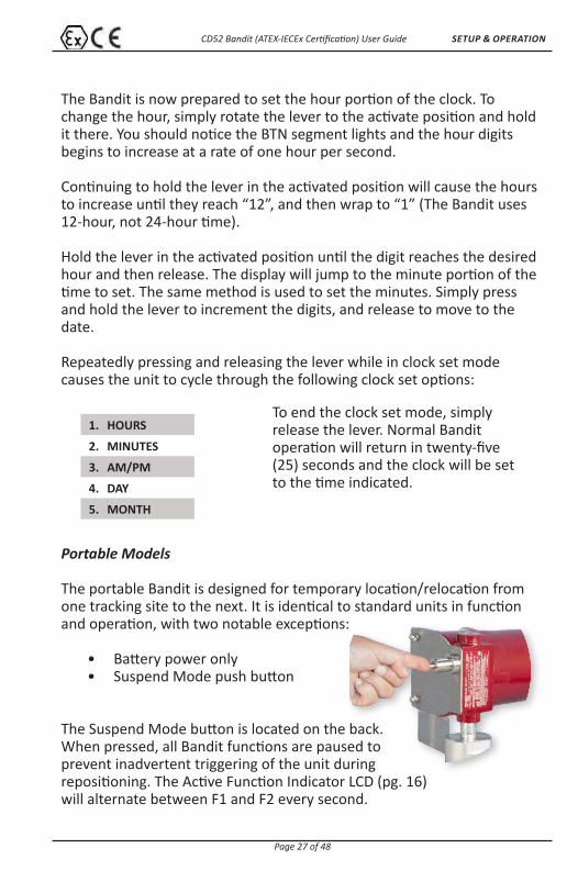
Portable Models
The portable Bandit is designed for temporary location/relocation from one tracking site to the next. It is identical to standard units in function and operation, with two notable exceptions:
• Battery power only • Suspend Mode push button
The Suspend Mode button is located on the back. When pressed, all Bandit functions are paused to prevent inadvertent triggering of the unit during repositioning. The Active Function Indicator LCD (pg. 16) will alternate between F1 and F2 every second.
The Bandit is now prepared to set the hour portion of the clock. To change the hour, simply rotate the lever to the activate position and hold it there. You should notice the BTN segment lights and the hour digits begins to increase at a rate of one hour per second.
Continuing to hold the lever in the activated position will cause the hoursto increase until they reach “12”, and then wrap to “1” (The Bandit uses 12-hour, not 24-hour time).
Hold the lever in the activated position until the digit reaches the desired hour and then release. The display will jump to the minute portion of the time to set. The same method is used to set the minutes. Simply press and hold the lever to increment the digits, and release to move to the date.
Repeatedly pressing and releasing the lever while in clock set mode causes the unit to cycle through the following clock set options:
1. HOURS
2. MINUTES
3. AM/PM
4. DAY
5. MONTH
To end the clock set mode, simply release the lever. Normal Bandit operation will return in twenty-five (25) seconds and the clock will be set to the time indicated.
CD52 Bandit (ATEX-IECEx Certification) User Guide
Page 28 of 48
INSTALLATION
When the portable Bandit is repositioned, pressing the Suspend button a second time readies the portable Bandit to resume passage detection. The Active Function Indicator F1–F2 cycle will cease.
INSTALLATION
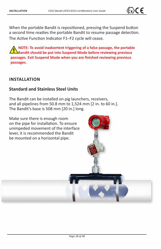
Standard and Stainless Steel Units
The Bandit can be installed on pig launchers, receivers,and all pipelines from 50.8 mm to 1,524 mm [2 in. to 60 in.]. The Bandit’s base is 508 mm [20 in.] long.
Make sure there is enough room on the pipe for installation. To ensure unimpeded movement of the interface lever, it is recommended the Bandit be mounted on a horizontal pipe.
NOTE: To avoid inadvertent triggering of a false passage, the portable Bandit should be put into Suspend Mode before reviewing previous
passages. Exit Suspend Mode when you are finished reviewing previous passages.

CD52 Bandit (ATEX-IECEx Certification) User Guide
Page 29 of 48
INSTALLATION
*CDI Part # 81–04–0008–00
1: Prep Banding
Prepare the band and buckle. Slide the buckle over the band and crimp in place.
2: Attach Base
Set the base on the pipeline. Loop the free end of the band through the slots at one end of the base.
Continue looping the free end around the pipe until it meets the buckle at the other end of the band.
Slide the free end of the band through the buckle.
NOTE: The banding material and band tension
tool* are stocked by CDI.
NOTE: The standard CD52 antenna base (shown here)
is of cast aluminum and must be handled with care. Do not over-torque bands.
If needed, use electrical insulators (see pg. 33) to prevent interference with cathodic rectifiers.

CD52 Bandit (ATEX-IECEx Certification) User Guide
Page 30 of 48
INSTALLATION
3: Attach Tensioning Tool
Thread free end through both jaws of tension tool.
Tighten the tension on the band using the tension tool.
4: Cut Excess
Raise the tension tool to bend the band back over the buckle.
Pull the cutoff lever and cut off the excess banding material.
5: Secure Buckle
Secure the buckle. Bend the end of the band down by lightly tapping with a hammer. Using a hammer, bend the two locking tabs over the end of the band.
NOTE: Do not over-torque bands on cast aluminum antenna base.
CD52 Bandit (ATEX-IECEx Certification) User Guide
Page 31 of 48
INSTALLATION
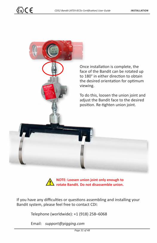
Once installation is complete, the face of the Bandit can be rotated up to 180° in either direction to obtain the desired orientation for optimum viewing.
To do this, loosen the union joint and adjust the Bandit face to the desired position. Re-tighten union joint.
If you have any difficulties or questions assembling and installing your Bandit system, please feel free to contact CDI:
Telephone (worldwide): +1 (918) 258–6068
Email: [email protected]
NOTE: Loosen union joint only enough to rotate Bandit. Do not disassemble union.

CD52 Bandit (ATEX-IECEx Certification) User Guide
Page 32 of 48
INSTALLATION
Armored Flex Cable Units
Bandit units configured with armored flex cable are shipped mounted on a plywood sheet with webbing straps. Special unpacking procedures should be followed:
Required tools/materials:
• Screw gun or Phillips screwdriver • Banding kit (supplied) • Batteries (supplied)
1. Lift mounted assembly with webbing handles only.
2. Remove antenna base unit strap using Phillips screw driver.
3. Uncoil cable. This requires two (2) personnel. Person #1 will hold antenna base (while supporting cable) and walk in an ever-widening circle. While walking, Person #1 will continually untwist the antenna base to prevent cable from kinking.
Person #2 will be responsible for uncoiling cable at the plastic spool.
4. Startup procedure is identical to that of standard units.
NOTE: Prepare an unobstructed 6 m x 6 m [20 ft x 20 ft] area before unpacking.
NOTE: Maintain a 152 mm [6 in.] minimum bend radius to avoid kinking or breaking the aluminum cable armor.

CD52 Bandit (ATEX-IECEx Certification) User Guide
Page 33 of 48
OPTIONAL EQUIPMENT
OPTIONAL EQUIPMENT
Remote Indicator System (RIS)
The Remote Indicator System (RIS) consists of four high-luminosity LEDs that, when pig passage occurs, can be seen over distances as great as 100 meters (328 ft].
The RIS may be added to any Bandit System.
Cathodic Protection Base Mounting
Cathodic protection insulation matting is available to protect pipeline coating.
Heater
A 24 VDC internal heater is available and recommended for operation in temperatures below –30°C [–22°F].
Heat Risers
Heat riser insulators for the CD52 Bandit allow the system to be used on geothermal pipeline, or other environments where pipeline surface temperatures exceed of 80°C [176°F].
NOTE: Heat risers enable the CD52 Bandit to operate with product temperatures greater than 80°C [176°F]. However, if the ambient air
environment of the system is greater than 70°C [158°F], it will be operating outside of ATEX/IECEx Certification.

CD52 Bandit (ATEX-IECEx Certification) User Guide
Page 34 of 48
OPTIONAL EQUIPMENT
LineStat
TRAXALL LineStat is a global, value-added satellite-based event notification service provided by CDI and targeted primarily to the oil and gas pipeline industry. LineStat provides notification to email addresses and SMS text messaging telephone numbers of remote events from both fixed position and portable equipment.
Some of the details included in event notification
messages are date, time, GPS position, battery status, and vibration.
This information is transmitted via satellite without use of cellular networks and without
need of a wired infrastructure.
Sunshade
The stainless steel sunshade can help protect the Bandit from intense sunlight by reducing overall temperature inside, thus prolonging the life of the electronic components. The sunshade’s 316 stainless steel construction guarantees long life in a harsh pipeline environment and is available for standard or enclosed units.

CD52 Bandit (ATEX-IECEx Certification) User Guide
Page 35 of 48
WARRANTY
Warranty
All equipment sold by Control Devices, Incorporated (CDI) is warranted for a period of one (1) year from the date of shipment to Purchaser, providing the instrument or equipment has not been modified, abused or used for purposes other than that for which it was designed.
Batteries, probes, leads, magnets and other consumables subject to wear are not covered by this warranty. CDI will repair or replace faulty equipment during the warranty period when the cause is a defect arising from faulty design, materials or workmanship.
Making a Warranty Claim
Equipment being considered for warranty repair, or a representative sample thereof, must be returned to CDI at the Purchaser’s expense. The goods must be accompanied by the Purchaser’s written order describing the defect(s) and authorizing CDI to invoice the Purchaser for any charges not covered by the warranty.
Upon receipt of the equipment and Purchase Order, CDI will examine the equipment and make a determination of the nature and cause of the defect. If the defect is not covered by the warranty, CDI will quote to Purchaser the cost for replacement or repair equipment, and will not proceed until Purchaser delivers a written acceptance of the quotation.
During the one year warranty, CDI will bear the cost to return units repaired under the warranty back to the Purchaser’s domestic premises. CDI will return units to foreign countries at Purchaser’s expense.
* Contact CDI at 1–800–580–4234, ext 143 for CDI RMA Form FM–03–0089
CD52 Bandit (ATEX-IECEx Certification) User Guide
Page 36 of 48
SERVICE & MAINTENANCE
Care and Maintenance
Equipment designed by CDI is protected against the environment in which it is intended to operate. Much of the equipment is designed for prolonged use in the field without any special maintenance other than routine battery replacements. It is the Purchaser’s responsibility to insure that proper precautions are taken during installation and operation so that weather seals are in place, routine maintenance occurs, etc. Failure to perform these operations nullifies this warranty.
CDI equipment should only be operated by qualified personnel who are familiar with any and all manuals and procedures for said equipment’s operation.
Operating equipment while in a damaged condition nullifies this warranty.
Service and Repairs
Cost for repairs not covered by the warranty or carried out after the warranty period has expired will be charged at the current hourly or set service rate, plus the cost of materials, upon approval by Purchaser.
Equipment for repair must be sent at the Purchaser’s expense and be accompanied by the Purchaser’s written order describing the defect and authorizing CDI to invoice the Purchaser for labor, materials and return delivery cost.
No service or repair will be undertaken until an approved written order is received from the Purchaser.
Operating equipment while in a damaged condition nullifies this warranty.
CD52 Bandit (ATEX-IECEx Certification) User Guide
Page 37 of 48
GEN ARRANGEMENT DWGS
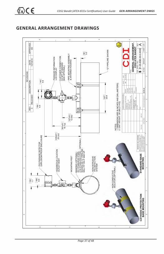
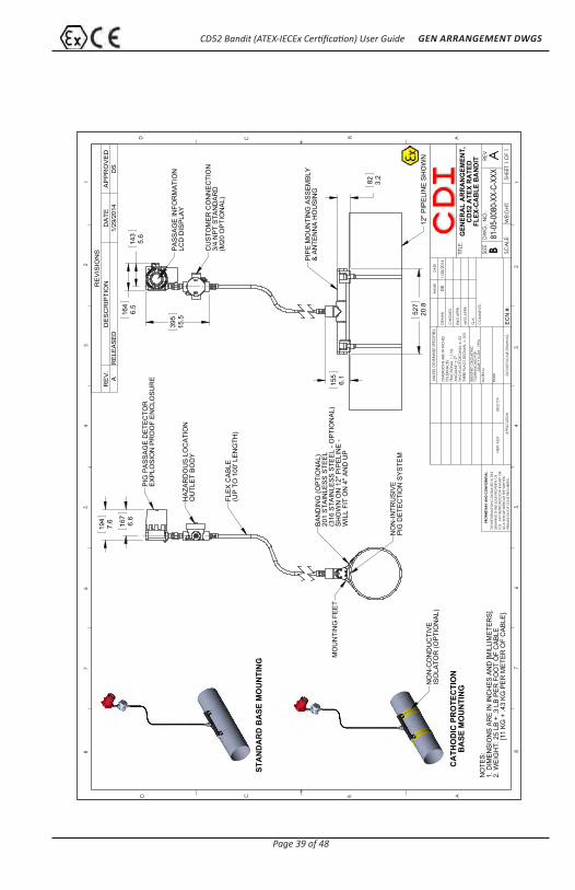
GENERAL ARRANGEMENT DRAWINGS
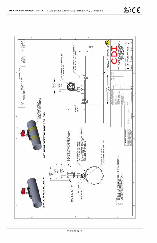
52
720
.8
82 3.
2
32
7±51
12.9
±2
50
1±51
19.7
±2
63
9±51
25.2
±2
14
35.
6
16
46.
5
12" P
IPE
LIN
E S
HO
WN
PIP
E M
OU
NTI
NG
AS
SE
MB
LY&
AN
TEN
NA
HO
US
ING
CU
STO
ME
R C
ON
NE
CTI
ON
3/4
NP
T S
TAN
DA
RD
(M20
OP
TIO
NA
L)
PA
SS
AG
E IN
FOR
MA
TIO
NLC
D D
ISP
LAY
19
57.
7
16
96.
6
NO
N-IN
TRU
SIV
EP
IG D
ETE
CTI
ON
SY
STE
M
BA
ND
ING
(OP
TIO
NA
L)20
1 S
TAIN
LES
S S
TEE
L(3
16 S
TAIN
LES
S S
TEE
L - O
PTI
ON
AL)
SH
OW
N O
N 1
2" P
IPE
LIN
E -
WIL
L FI
T O
N 4
" AN
D U
P
HA
ZAR
DO
US
LO
CA
TIO
NO
UTL
ET
BO
DY
PIG
PA
SS
AG
E D
ETE
CTO
RE
XP
LOS
ION
PR
OO
F E
NC
LOS
UR
E
MO
UN
TIN
G F
EE
T
STA
ND
AR
D B
ASE
MO
UN
TIN
GC
ATH
OD
IC P
RO
TEC
TIO
NB
ASE
MO
UN
TIN
G
NO
N-C
ON
DU
CTI
VE
ISO
LATO
R (O
PTI
ON
AL)
NO
TES:
1. D
IMEN
SIO
NS
ARE
IN IN
CH
ES A
ND
[MIL
LIM
ETER
S].
2. U
NIT
WEI
GH
T: 2
8 LB
S [1
3 KG
].
RE
VIS
ION
SR
EV
.D
ES
CR
IPT
ION
DA
TE
AP
PR
OV
ED
AR
ELE
AS
ED
1/27
/201
4D
S
D C B AABCD
12
34
56
788
76
54
32
1
THE
INFO
RMA
TION
CO
NTA
INED
IN T
HIS
DRA
WIN
G IS
THE
SO
LE P
ROPE
RTY
OF
CD
I. A
NY
REPR
OD
UCTIO
N IN
PA
RT O
RA
S A
WHO
LE W
ITHO
UT T
HE W
RITT
ENPE
RMIS
SIO
N O
F C
DI I
S PR
OHI
BITE
D.
PRO
PRIE
TARY
AN
D C
ON
FIDE
NTIA
L
NEX
T A
SSY
USED
ON
APP
LICA
TION
DIM
ENSI
ON
S A
RE IN
INC
HES
TOLE
RAN
CES
:FR
AC
TION
AL
1/3
2A
NG
ULA
R:
2TW
O P
LAC
E D
ECIM
AL
.03
THRE
E PL
AC
E D
ECIM
AL
.010
MA
TERI
AL
FIN
ISH
DRA
WN
CHE
CKE
D
ENG
APP
R.
MFG
APP
R.
Q.A
.
CO
MM
ENTS
:
DA
TEN
AM
E
TITLE
:
SIZE B
DW
G.
NO
.RE
V
WEI
GHT
: SC
ALE
:
UNLE
SS O
THER
WIS
E SP
ECIF
IED
:
A
GEN
ERA
L A
RR
AN
GEM
ENT,
CD
52 A
TEX
BA
ND
IT
SHEE
T 1 O
F 1
81-05-0080-XX-0-XX
XED
O N
OT
SCA
LE D
RAW
ING
INTE
RPRE
T G
EOM
ETRI
CTO
LERA
NC
ING
PER
:
ASM
E Y1
4.5M
- 19
94
DS
01/2
7/20
14
ECN
#:

CD52 Bandit (ATEX-IECEx Certification) User Guide
Page 38 of 48
GEN ARRANGEMENT DWGS
52
720
.8
82 3.
2
6.9
±1
12.
3±1
60
96 M
AX
240.
0 M
AX
14
35.
6
16
46.
5
12" P
IPE
LIN
E S
HO
WN
PIP
E M
OU
NTI
NG
AS
SE
MB
LY&
AN
TEN
NA
MO
UN
TIN
G
CU
STO
ME
R C
ON
NE
CTI
ON
,3/
4 N
PT
STA
ND
AR
D(M
20 O
PTI
ON
AL)
PA
SS
AG
E IN
FOR
MA
TIO
NLC
D D
ISP
LAY
19
57.
7
16
76.
6
NO
N-IN
TRU
SIV
EP
IG D
ETE
CTI
ON
SY
STE
M
AN
TEN
NA
BA
ND
ING
(OP
TIO
NA
L)20
1 S
TAIN
LES
S S
TEE
L(3
16 S
TAIN
LES
S S
TEE
L - O
PTI
ON
AL)
SH
OW
N O
N 1
2" P
IPE
LIN
E -
WIL
L FI
T O
N 4
" AN
D U
PM
OU
NTI
NG
FE
ET
PIP
E E
XTE
NS
ION
MA
X. O
VE
RA
LL H
EIG
HT:
240
" [60
96]
HA
ZAR
DO
US
LO
CA
TIO
NO
UTL
ET
BO
DY
PIG
PA
SS
AG
E D
ETE
CTO
RE
XP
LOS
ION
PR
OO
F E
NC
LOS
UR
E
STA
ND
AR
D B
ASE
MO
UN
TIN
G
CA
THO
DIC
PR
OTE
CTI
ON
BA
SE M
OU
NTI
NGN
ON
-CO
ND
UC
TIV
EIS
OLA
TOR
(OP
TIO
NA
L)
NO
TES:
1. D
IMEN
SIO
NS
ARE
IN IN
CH
ES A
ND
[MIL
LIM
ETER
S].
2. U
NIT
WEI
GH
T: 3
0 LB
S +
3.7
LBS
PER
FO
OT
OF
EXTE
NSI
ON
[
13.6
KG
+ 5
.4 K
G P
ER M
ETER
OF
EXTE
NSI
ON
].
RE
VIS
ION
SR
EV
.D
ES
CR
IPT
ION
DA
TE
AP
PR
OV
ED
AR
ELE
AS
ED
2/5/
2014
DS
D C B AABCD
12
34
56
788
76
54
32
1
THE
INFO
RMA
TION
CO
NTA
INED
IN T
HIS
DRA
WIN
G IS
THE
SO
LE P
ROPE
RTY
OF
CD
I. A
NY
REPR
OD
UCTIO
N IN
PA
RT O
RA
S A
WHO
LE W
ITHO
UT T
HE W
RITT
ENPE
RMIS
SIO
N O
F C
DI I
S PR
OHI
BITE
D.
PRO
PRIE
TARY
AN
D C
ON
FIDE
NTIA
L
NEX
T A
SSY
USED
ON
APP
LICA
TION
DIM
ENSI
ON
S A
RE IN
INC
HES
TOLE
RAN
CES
:FR
AC
TION
AL
1/3
2A
NG
ULA
R:
2TW
O P
LAC
E D
ECIM
AL
.03
THRE
E PL
AC
E D
ECIM
AL
.010
MA
TERI
AL
FIN
ISH
DRA
WN
CHE
CKE
D
ENG
APP
R.
MFG
APP
R.
Q.A
.
CO
MM
ENTS
:
DA
TEN
AM
E
TITLE
:
SIZE B
DW
G.
NO
.RE
V
WEI
GHT
: SC
ALE
:
UNLE
SS O
THER
WIS
E SP
ECIF
IED
:
A
GEN
ERA
L A
RR
AN
GEM
ENT,
CD
52 A
TEX
BA
ND
IT W
ITH
PIPE
EXT
ENSI
ON
SHEE
T 1 O
F 1
81-05-0080-XX-P-XX
XED
O N
OT
SCA
LE D
RAW
ING
INTE
RPRE
T G
EOM
ETRI
CTO
LERA
NC
ING
PER
:
ASM
E Y1
4.5M
- 19
94
DS
2/5/
2014
ECN
#:
CD52 Bandit (ATEX-IECEx Certification) User Guide
Page 39 of 48
GEN ARRANGEMENT DWGS
52
720
.8
82 3.
2
15
56.
1
39
515
.5
16
46.
5
14
35.
6
12" P
IPE
LIN
E S
HO
WN
PIP
E M
OU
NTI
NG
AS
SE
MB
LY&
AN
TEN
NA
HO
US
ING
CU
STO
ME
R C
ON
NE
CTI
ON
3/4
NP
T S
TAN
DA
RD
(M20
OP
TIO
NA
L)
PA
SS
AG
E IN
FOR
MA
TIO
NLC
D D
ISP
LAY
19
47.
6
16
76.
6
FLE
X C
AB
LE(U
P T
O 1
00' L
EN
GTH
)
PIG
PA
SS
AG
E D
ETE
CTO
RE
XP
LOS
ION
PR
OO
F E
NC
LOS
UR
E
NO
N-IN
TRU
SIV
EP
IG D
ETE
CTI
ON
SY
STE
M
BA
ND
ING
(OP
TIO
NA
L)20
1 S
TAIN
LES
S S
TEE
L(3
16 S
TAIN
LES
S S
TEE
L - O
PTI
ON
AL)
SH
OW
N O
N 1
2" P
IPE
LIN
E -
WIL
L FI
T O
N 4
" AN
D U
PM
OU
NTI
NG
FE
ET
HA
ZAR
DO
US
LO
CA
TIO
NO
UTL
ET
BO
DY
CA
THO
DIC
PR
OTE
CTI
ON
BA
SE M
OU
NTI
NG
NO
N-C
ON
DU
CTI
VE
ISO
LATO
R (O
PTI
ON
AL)
STA
ND
AR
D B
ASE
MO
UN
TIN
G
NO
TES:
1. D
IMEN
SIO
NS
ARE
IN IN
CH
ES A
ND
[MIL
LIM
ETER
S].
2. W
EIG
HT:
25
LB +
.3 L
B PE
R F
OO
T O
F C
ABLE
[11
KG
+ .4
3 KG
PER
MET
ER O
F C
ABLE
].
RE
VIS
ION
SR
EV
.D
ES
CR
IPT
ION
DA
TE
AP
PR
OV
ED
AR
ELE
AS
ED
1/29
/201
4D
S
D C B AABCD
12
34
56
788
76
54
32
1
THE
INFO
RMA
TION
CO
NTA
INED
IN T
HIS
DRA
WIN
G IS
THE
SO
LE P
ROPE
RTY
OF
CD
I. A
NY
REPR
OD
UCTIO
N IN
PA
RT O
RA
S A
WHO
LE W
ITHO
UT T
HE W
RITT
ENPE
RMIS
SIO
N O
F C
DI I
S PR
OHI
BITE
D.
PRO
PRIE
TARY
AN
D C
ON
FIDE
NTIA
L
NEX
T A
SSY
USED
ON
APP
LICA
TION
DIM
ENSI
ON
S A
RE IN
INC
HES
TOLE
RAN
CES
:FR
AC
TION
AL
1/3
2A
NG
ULA
R:
2TW
O P
LAC
E D
ECIM
AL
.03
THRE
E PL
AC
E D
ECIM
AL
.010
MA
TERI
AL
FIN
ISH
DRA
WN
CHE
CKE
D
ENG
APP
R.
MFG
APP
R.
Q.A
.
CO
MM
ENTS
:
DA
TEN
AM
E
TITLE
:
SIZE B
DW
G.
NO
.RE
V
WEI
GHT
: SC
ALE
:
UNLE
SS O
THER
WIS
E SP
ECIF
IED
:
A
GEN
ERA
L A
RR
AN
GEM
ENT,
CD
52 A
TEX
RA
TED
FLEX
-CA
BLE
BA
ND
IT
SHEE
T 1 O
F 1
81-05-0080-XX-C-XX
XD
O N
OT
SCA
LE D
RAW
ING
INTE
RPRE
T G
EOM
ETRI
CTO
LERA
NC
ING
PER
:
ASM
E Y1
4.5M
- 19
94
DS
1/28
/201
4
ECN
#:
CD52 Bandit (ATEX-IECEx Certification) User Guide
Page 40 of 48
GEN ARRANGEMENT DWGS
52
720
.8
82 3.
2
34
3±25
13.5
±1
14
35.
6
16
76.
6
SH
OW
N O
N 1
2" P
IPE
LIN
E
PIP
E M
OU
NTI
NG
AS
SE
MB
LY&
AN
TEN
NA
HO
US
ING
PA
SS
AG
E IN
FOR
MA
TIO
NLC
D D
ISP
LAY
19
77.
8
25
610
.1
16
76.
6
PIG
PA
SS
AG
E D
ETE
CTO
RE
XP
LOS
ION
PR
OO
F E
NC
LOS
UR
E
BA
ND
ING
(OP
TIO
NA
L)20
1 S
TAIN
LES
S S
TEE
L(3
16 S
TAIN
LES
S S
TEE
L - O
PTI
ON
AL)
SH
OW
N O
N 1
2" P
IPE
LIN
E -
WIL
L FI
T O
N 4
" AN
D U
P
AN
TEN
NA
MO
UN
TIN
G F
EE
T
SU
SP
EN
D B
UTT
ON
NO
N-IN
TRU
SIV
EP
IG D
ETE
CTI
ON
SY
STE
M
STA
ND
AR
D B
ASE
MO
UN
TIN
GC
ATH
OD
IC P
RO
TEC
TIO
N B
ASE
MO
UN
TIN
G
NO
N-C
ON
DU
CTI
VE
ISO
LATO
R (O
PTI
ON
AL)
NO
TES: DIM
ENSI
ON
S AR
E IN
INC
HES
AN
D [M
ILLI
MET
ERS]
.1.
WEI
GH
T: 2
1 LB
S [9
.5 K
G].
2.U
SES
BATT
ERY
POW
ER O
NLY
.3.
RE
VIS
ION
SR
EV
.D
ES
CR
IPT
ION
DA
TE
AP
PR
OV
ED
AR
ELE
AS
ED
2/7/
2014
DS
D C B AABCD
12
34
56
788
76
54
32
1
THE
INFO
RMA
TION
CO
NTA
INED
IN T
HIS
DRA
WIN
G IS
THE
SO
LE P
ROPE
RTY
OF
CD
I. A
NY
REPR
OD
UCTIO
N IN
PA
RT O
RA
S A
WHO
LE W
ITHO
UT T
HE W
RITT
ENPE
RMIS
SIO
N O
F C
DI I
S PR
OHI
BITE
D.
PRO
PRIE
TARY
AN
D C
ON
FIDE
NTIA
L
NEX
T A
SSY
USED
ON
APP
LICA
TION
DIM
ENSI
ON
S A
RE IN
INC
HES
TOLE
RAN
CES
:FR
AC
TION
AL
1/3
2A
NG
ULA
R:
2TW
O P
LAC
E D
ECIM
AL
.03
THRE
E PL
AC
E D
ECIM
AL
.010
MA
TERI
AL
FIN
ISH
DRA
WN
CHE
CKE
D
ENG
APP
R.
MFG
APP
R.
Q.A
.
CO
MM
ENTS
:
DA
TEN
AM
E
TITLE
:
SIZE B
DW
G.
NO
.RE
V
WEI
GHT
: SC
ALE
:
UNLE
SS O
THER
WIS
E SP
ECIF
IED
:
A
GENE
RAL A
RRAN
GEME
NT,
CD52
POR
TABL
EAT
EX B
ANDI
T
SHEE
T 1 O
F 1
81-0
5-00
80-P
0-0-
000E
DO
NO
T SC
ALE
DRA
WIN
G
INTE
RPRE
T G
EOM
ETRI
CTO
LERA
NC
ING
PER
:
ASM
E Y1
4.5M
- 19
94
DS
2/7/
2014
ECN
#:

CD52 Bandit (ATEX-IECEx Certification) User Guide
Page 41 of 48
GEN ARRANGEMENT DWGS
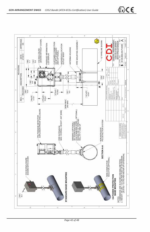
25
410
.0
24
19.
5
23
7±51
9.3±
2
141±
255.
5±1
33
8±51
13.3
±2
61
1±51
24.0
±2
72
5±51
28.6
±2
16
56.
5
39
215
.4
14
35.
6
19
67.
7
A
A12
" PIP
ELI
NE
SH
OW
N
PIP
E M
OU
NTI
NG
AS
SE
MB
LY
AN
TEN
NA
HO
US
ING
316
SS
EN
CLO
SU
RE
(SH
OW
N W
ITH
OU
T C
OV
ER
)
PA
SS
AG
E IN
FOR
MA
TIO
NLC
D D
ISP
LAY
BA
ND
ING
(OP
TIO
NA
L),
201
STA
INLE
SS
STE
EL
(316
STA
INLE
SS
STE
EL
- OP
TIO
NA
L)S
HO
WN
ON
12"
PIP
ELI
NE
-W
ILL
FIT
ON
4" A
ND
UP
HA
ZAR
DO
US
LO
CA
TIO
NO
UTL
ET
BO
DY
CU
STO
ME
R C
ON
NE
CTI
ON
3/4
NP
T S
TAN
DA
RD
(M20
OP
TIO
NA
L)
36
7±25
14.4
3±1
12
95.
1
44 1.
7 SE
CTI
ON
A-A
NO
N-IN
TRU
SIV
EP
IG D
ETE
CTI
ON
SY
STE
M
PIG
PA
SS
AG
E D
ETE
CTO
RE
XP
LOS
ION
PR
OO
F E
NC
LOS
UR
E
23
59.
3
316
SS
EN
CLO
SU
RE
SH
OW
N W
ITH
CO
VE
R
NO
N-C
ON
DU
CTI
VE
ISO
LATO
R (O
PTI
ON
AL)
CA
THO
DIC
PR
OTE
CTI
ON
BA
SE M
OU
NTI
NG
STA
ND
AR
D B
ASE
MO
UN
TIN
G
NO
TES:
1. D
IMEN
SIO
NS
ARE
IN IN
CH
ES A
ND
[MIL
LIM
ETER
S].
2. W
EIG
HT:
63
LBS
[29
KG].
RE
VIS
ION
SR
EV
.D
ES
CR
IPT
ION
DA
TE
AP
PR
OV
ED
AR
ELE
AS
ED
1/20
/201
4D
S
D C B AABCD
12
34
56
788
76
54
32
1
THE
INFO
RMA
TION
CO
NTA
INED
IN T
HIS
DRA
WIN
G IS
THE
SO
LE P
ROPE
RTY
OF
CD
I. A
NY
REPR
OD
UCTIO
N IN
PA
RT O
RA
S A
WHO
LE W
ITHO
UT T
HE W
RITT
ENPE
RMIS
SIO
N O
F C
DI I
S PR
OHI
BITE
D.
PRO
PRIE
TARY
AN
D C
ON
FIDE
NTIA
L
NEX
T A
SSY
USED
ON
APP
LICA
TION
DIM
ENSI
ON
S A
RE IN
INC
HES
TOLE
RAN
CES
:FR
AC
TION
AL
1/3
2A
NG
ULA
R:
2TW
O P
LAC
E D
ECIM
AL
.03
THRE
E PL
AC
E D
ECIM
AL
.010
MA
TERI
AL
FIN
ISH
DRA
WN
CHE
CKE
D
ENG
APP
R.
MFG
APP
R.
Q.A
.
CO
MM
ENTS
:
DA
TEN
AM
E
TITLE
:
SIZE B
DW
G.
NO
.RE
V
WEI
GHT
: SC
ALE
:
UNLE
SS O
THER
WIS
E SP
ECIF
IED
:
A
GEN
ERA
L A
RR
AN
GEM
ENT,
CD
52 S
S A
TEX
BA
ND
IT
SHEE
T 1 O
F 1
81-05-0063-XX-0-XX
XED
O N
OT
SCA
LE D
RAW
ING
INTE
RPRE
T G
EOM
ETRI
CTO
LERA
NC
ING
PER
:
ASM
E Y1
4.5M
- 19
94
DS
1/20
/201
4
ECN
#:
CD52 Bandit (ATEX-IECEx Certification) User Guide
Page 42 of 48
GEN ARRANGEMENT DWGS
24
19.
5
25
410
.0
14
1±25
5.5±
1
27
3±51
10.8
±2
94
±25
3.7±
1
27
0±25
10.6
±1
60
96 M
AX
240
MA
X
39
215
.4
14
35.
6
16
56.
5
19
67.
7
A
A12
" PIP
ELI
NE
SH
OW
N
PIP
E M
OU
NTI
NG
AS
SE
MB
LY
AN
TEN
NA
HO
US
ING
HA
ZAR
DO
US
LO
CA
TIO
NO
UTL
ET
BO
DY
CU
STO
ME
R C
ON
NE
CTI
ON
3/4
NP
T S
TAN
DA
RD
(M20
OP
TIO
NA
L)
PA
SS
AG
E IN
FOR
MA
TIO
NLC
D D
ISP
LAY
316
EN
CLO
SU
RE
(SH
OW
N W
ITH
OU
T C
OV
ER
)
SEC
TIO
N A
-A
PIP
E E
XTE
NS
ION
MA
X. O
VE
RA
LL H
EIG
HT:
240
" [60
96]
NO
N-IN
TRU
SIV
EP
IG D
ETE
CTI
ON
SY
STE
M
BA
ND
ING
(OP
TIO
NA
L)20
1 S
TAIN
LES
S S
TEE
L(3
16 S
TAIN
LES
S S
TEE
L - O
PTI
ON
AL)
SH
OW
N O
N 1
2" P
IPE
LIN
E -
WIL
L FI
T 4"
AN
D U
P
PIG
PA
SS
AG
E D
ETE
CTO
RE
XP
LOS
ION
PR
OO
F E
NC
LOS
UR
E
CA
THO
DIC
PR
OTE
CTI
ON
BA
SE M
OU
NTI
NG
NO
N-C
ON
DU
CTI
VE
ISO
LATO
R (O
PTI
ON
AL)
23
59.
3
STA
ND
AR
D B
ASE
MO
UN
TIN
G
316
SS
EN
CLO
SU
RE
SH
OW
N W
ITH
CO
VE
R
NO
TES:
1. D
IMEN
SIO
NS
ARE
IN IN
CH
ES A
ND
[MIL
LIM
ETER
S].
2. W
EIG
HT:
68
LBS
+ 3.
6 LB
S PE
R F
OO
T O
F EX
TEN
SIO
N
[
30.8
KG
+ 5
.6 K
G P
ER M
ETER
OF
EXTE
NSI
ON
].
RE
VIS
ION
SR
EV
.D
ES
CR
IPT
ION
DA
TE
AP
PR
OV
ED
AR
ELE
AS
ED
2/7/
2014
DS
D C B AABCD
12
34
56
788
76
54
32
1
THE
INFO
RMA
TION
CO
NTA
INED
IN T
HIS
DRA
WIN
G IS
THE
SO
LE P
ROPE
RTY
OF
CD
I. A
NY
REPR
OD
UCTIO
N IN
PA
RT O
RA
S A
WHO
LE W
ITHO
UT T
HE W
RITT
ENPE
RMIS
SIO
N O
F C
DI I
S PR
OHI
BITE
D.
PRO
PRIE
TARY
AN
D C
ON
FIDE
NTIA
L
NEX
T A
SSY
USED
ON
APP
LICA
TION
DIM
ENSI
ON
S A
RE IN
INC
HES
TOLE
RAN
CES
:FR
AC
TION
AL
1/3
2A
NG
ULA
R:
2TW
O P
LAC
E D
ECIM
AL
.03
THRE
E PL
AC
E D
ECIM
AL
.010
MA
TERI
AL
FIN
ISH
DRA
WN
CHE
CKE
D
ENG
APP
R.
MFG
APP
R.
Q.A
.
CO
MM
ENTS
:
DA
TEN
AM
E
TITLE
:
SIZE B
DW
G.
NO
.RE
V
WEI
GHT
: SC
ALE
:
UNLE
SS O
THER
WIS
E SP
ECIF
IED
:
A
GENE
RAL A
RRAN
GEME
NT,
CD52
SS
ATEX
BAN
DIT
WIT
H PI
PE E
XTEN
SION
SHEE
T 1 O
F 1
81-0
5-00
63-X
X-P-
XXXE
DO
NO
T SC
ALE
DRA
WIN
G
INTE
RPRE
T G
EOM
ETRI
CTO
LERA
NC
ING
PER
:
ASM
E Y1
4.5M
- 19
94
DS
2/6/
2014
ECN
#:
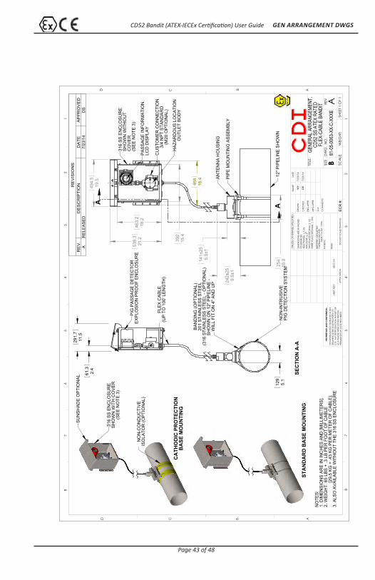
CD52 Bandit (ATEX-IECEx Certification) User Guide
Page 43 of 48
GEN ARRANGEMENT DWGS
14
1±25
5.5±
1
24
2±25
9.5±
1
25
410
.0
46
3.2
18.2
539.
321
.2
39
215
.4
46
818
.4
49
4.5
19.5
A A
12" P
IPE
LIN
E S
HO
WN
PIP
E M
OU
NTI
NG
AS
SE
MB
LY
AN
TEN
NA
HO
US
ING
HA
ZAR
DO
US
LO
CA
TIO
NO
UTL
ET
BO
DY
CU
STO
ME
R C
ON
NE
CTI
ON
3/4
NP
T S
TAN
DA
RD
(M20
OP
TIO
NA
L)
PA
SS
AG
E IN
FOR
MA
TIO
NLC
D D
ISP
LAY
316
SS
EN
CLO
SU
RE
SH
OW
N W
ITH
OU
TC
OV
ER
(SE
E N
OTE
3)
12
95.
1
29
1.7
11.5
61
.32.
4
SEC
TIO
N A
-A
BA
ND
ING
(OP
TIO
NA
L)20
1 S
TAIN
LES
S S
TEE
L(3
16 S
TAIN
LES
S S
TEE
L - O
PTI
ON
AL)
SH
OW
N O
N 1
2" P
IPE
LIN
E -
WIL
L FI
T O
N 4
" AN
D U
P
NO
N-IN
TRU
SIV
EP
IG D
ETE
CTI
ON
SY
STE
M
FLE
X C
AB
LE(U
P T
O 1
00' L
EN
GTH
)
PIG
PA
SS
AG
E D
ETE
CTO
RE
XP
LOS
ION
PR
OO
F E
NC
LOS
UR
E
STA
ND
AR
D B
ASE
MO
UN
TIN
G
316
SS
EN
CLO
SU
RE
SH
OW
N W
ITH
CO
VE
R(S
EE
NO
TE 3
)
NO
N-C
ON
DU
CTI
VE
ISO
LATO
R (O
PTI
ON
AL)
CA
THO
DIC
PR
OTE
CTI
ON
BA
SE M
OU
NTI
NG
SU
NS
HA
DE
OP
TIO
NA
L
NO
TES:
1. D
IMEN
SIO
NS
ARE
IN IN
CH
ES A
ND
[MIL
LIM
ETER
S].
2. W
EIG
HT:
65
LBS
+ .3
LB
PER
FO
OT
OF
CAB
LE
[
29.5
KG
+ .4
3 KG
PER
MET
ER O
F C
ABLE
].3.
ALS
O A
VAIL
ABLE
WIT
HO
UT
THE
316
SS E
NC
LOSU
RE
RE
VIS
ION
SR
EV
.D
ES
CR
IPT
ION
DA
TE
AP
PR
OV
ED
AR
ELE
AS
ED
7/23
/14
DS
D C B AABCD
12
34
56
788
76
54
32
1
THE
INFO
RMA
TION
CO
NTA
INED
IN T
HIS
DRA
WIN
G IS
THE
SO
LE P
ROPE
RTY
OF
CD
I. A
NY
REPR
OD
UCTIO
N IN
PA
RT O
RA
S A
WHO
LE W
ITHO
UT T
HE W
RITT
ENPE
RMIS
SIO
N O
F C
DI I
S PR
OHI
BITE
D.
PRO
PRIE
TARY
AN
D C
ON
FIDE
NTIA
L
NEX
T A
SSY
USED
ON
APP
LICA
TION
DIM
ENSI
ON
S A
RE IN
INC
HES
TOLE
RAN
CES
:FR
AC
TION
AL
1/3
2A
NG
ULA
R:
2TW
O P
LAC
E D
ECIM
AL
.03
THRE
E PL
AC
E D
ECIM
AL
.010
MA
TERI
AL
FIN
ISH
DRA
WN
CHE
CKE
D
ENG
APP
R.
MFG
APP
R.
Q.A
.
CO
MM
ENTS
:
DA
TEN
AM
E
TITLE
:
SIZE B
DW
G.
NO
.RE
V
WEI
GHT
: SC
ALE
:
UNLE
SS O
THER
WIS
E SP
ECIF
IED
:
A
GENE
RAL A
RRAN
GEME
NT,
CD52
SS
ATEX
RAT
EDFL
EX-C
ABLE
BAN
DIT
SHEE
T 1 O
F 1
81-0
5-00
63-X
X-C-
XXXE
DO
NO
T SC
ALE
DRA
WIN
G
INTE
RPRE
T G
EOM
ETRI
CTO
LERA
NC
ING
PER
:
ASM
E Y1
4.5M
- 19
94
WY
7/23
/14
ECR
#:
DS
7/23
/14

CD52 Bandit (ATEX-IECEx Certification) User Guide
Page 44 of 48
GEN ARRANGEMENT DWGS
25
410
.0
24
19.
5
14
1±25
5.5±
1
43
0±25
16.9
±1
14
35.
6
16
76.
6
SH
OW
N O
N 1
2" P
IPE
LIN
E
PIP
E M
OU
NTI
NG
AS
SE
MB
LY
AN
TEN
NA
HO
US
ING
PA
SS
AG
E IN
FOR
MA
TIO
NLC
D D
ISP
LAY
19
77.
8
25
610
.1
12
95.
1 16
76.
6
NO
N-IN
TRU
SIV
EP
IG D
ETE
CTI
ON
SY
STE
M
BA
ND
ING
(OP
TIO
NA
L)20
1 S
TAIN
LES
S S
TEE
L(3
16 S
TAIN
LES
S S
TEE
L - O
PTI
ON
AL)
SH
OW
N O
N 1
2" P
IPE
LIN
E -
WIL
L FI
T O
N 4
" AN
D U
P
PIG
PA
SS
AG
E D
ETE
CTO
RE
XP
LOS
ION
PR
OO
F E
NC
LOS
UR
E
STA
ND
AR
D B
ASE
MO
UN
TIN
GC
ATH
OD
IC P
RO
TEC
TIO
NB
ASE
MO
UN
TIN
G
NO
N-C
ON
DU
CTI
VE
ISO
LATO
R (O
PTI
ON
AL)
AN
TEN
NA
SU
SP
EN
D B
UTT
ON
NO
TES:
1. D
IMEN
SIO
NS
ARE
IN IN
CH
ES A
ND
[MIL
LIM
ETER
S].
2. W
EIG
HT:
26
LBS
[11.
8 KG
].3.
USE
S BA
TTER
Y PO
WER
ON
LY.
RE
VIS
ION
SR
EV
.D
ES
CR
IPT
ION
DA
TE
AP
PR
OV
ED
AR
ELE
AS
ED
2/10
/201
4D
S
D C B AABCD
12
34
56
788
76
54
32
1
THE
INFO
RMA
TION
CO
NTA
INED
IN T
HIS
DRA
WIN
G IS
THE
SO
LE P
ROPE
RTY
OF
CD
I. A
NY
REPR
OD
UCTIO
N IN
PA
RT O
RA
S A
WHO
LE W
ITHO
UT T
HE W
RITT
ENPE
RMIS
SIO
N O
F C
DI I
S PR
OHI
BITE
D.
PRO
PRIE
TARY
AN
D C
ON
FIDE
NTIA
L
NEX
T A
SSY
USED
ON
APP
LICA
TION
DIM
ENSI
ON
S A
RE IN
INC
HES
TOLE
RAN
CES
:FR
AC
TION
AL
1/3
2A
NG
ULA
R:
2TW
O P
LAC
E D
ECIM
AL
.03
THRE
E PL
AC
E D
ECIM
AL
.010
MA
TERI
AL
FIN
ISH
DRA
WN
CHE
CKE
D
ENG
APP
R.
MFG
APP
R.
Q.A
.
CO
MM
ENTS
:
DA
TEN
AM
E
TITLE
:
SIZE B
DW
G.
NO
.RE
V
WEI
GHT
: SC
ALE
:
UNLE
SS O
THER
WIS
E SP
ECIF
IED
:
A
GENE
RAL A
RRAN
GEME
NT,
CD52
SS
PORT
ABLE
ATEX
BAN
DIT
SHEE
T 1 O
F 1
81-0
5-00
63-P
0-0-
000E
DO
NO
T SC
ALE
DRA
WIN
G
INTE
RPRE
T G
EOM
ETRI
CTO
LERA
NC
ING
PER
:
ASM
E Y1
4.5M
- 19
94
DS
2/10
/201
4
ECN
#: