celeron mother board.pdf
TRANSCRIPT
8/16/2019 celeron mother board.pdf
http://slidepdf.com/reader/full/celeron-mother-boardpdf 1/32
1
Manual Rev. A
CONTENTS
I tem Checklist
Please check that your package is complete. If you discover damaged or
missing items, please contact your retailer.
Motherboard x 1
40-pin IDE Connector Flat Cable x 1
34-pin Floppy Disk Drive Flat Cable x 1User Manual x 1; CD x 1
COM 2 Connector Flat Cable x 1
Option : Components will be include upon customer ordering instructions
per Proforma Invoice & additional external procurement cost will be
included.
1. Specification ................................................................... 22. Parts Of The Mother Board .................................................. 4
3. MotherBoard Layout Quick View ............................................ 5
4. Installation .................................................................... 6
4-1 Jumper Overview 6
4-2 CPU Setting 8
4-3 Install System Memory Modules 9
4-4 External Conncetion 104-5 ATX Power Supply Connector 11
4-6 KeyBoard , Mouse, USB, COM / LPT / VGA / Sound 12
4-7 Front Panel Connection 14
4-8 FAN, IR, WOL, CD IN Connector 15
4-9 Power On Procedure 17
Appendix: BIOS Setup Tips...................................................... 18

8/16/2019 celeron mother board.pdf
http://slidepdf.com/reader/full/celeron-mother-boardpdf 2/32
2
Manual Rev. A
1. Specification
Microprocessor
č Supports for a single Pentium II and Pentium III or Celeron processor
č Optional CPU card to support PPGA Celeron
č Supports 66/75/83/100 MHz host bus clock, selectable by jumpers
č Slot 1 connector
Cache and System Memory
č 0K/128K/512KB cache, built in Pentium II and Pentium III or Celeron
processorč 3 x 168 pin dual in line memory module (DIMM) sockets
č Support up to 768 MB of synchronous DRAM (SDRAM)
Chipset (SiS 620/5595 PCI AGP/VGA chip set)
č SiS 620 PCI/AGP VGA controller
Integrated AGP VGA for hardware 2D/3D video/graphics accelerators
Integrated PCI bus mastering controller
Integrated DRAM controllerč SiS 5595 PCI system I/O controller
Multifunction PCI-to-ISA bridge
Universal Serial Bus (USB) and DMA controllers
Two fast IDE interfaces that support up to four IDE drives or devices
Power management logic
Real-time clock
Video/Graphics Subsystemsč Integrated high performance & high quality AGP 2D/3D accelerator
č Programmable 2MB, 4MB, and 8MB shared frame buffer
č Optional 4MB or 8MB local frame buffer (manufacturing option)
č 24 bit true color RAMDAC up to 230MHz pixel clock, supports
1024*768 8/16/32 bpp @85Hz NI
č DVD hardware accelerator

8/16/2019 celeron mother board.pdf
http://slidepdf.com/reader/full/celeron-mother-boardpdf 3/32
3
Manual Rev. A
Audio Subsystemsč ESS solo1 PCI 3D single chip audio controller
č Mic-in, Line-in, Line-out, MIDI/Game port
I/O Features
č 1 x FDD Port support up to 2.88MB
č 1 x Parallel Port (LPT) support ECP/EPP
č 2 x High Speed Serial (16C550 UART) Ports
č 2 x IDE Ports support Ultra DMA/33
č 2 x Universal Serial Bus (USB) Ports
č 1 x PS/2 Keyboard Port
č 1 x PS/2 Mouse Port
č 1 x IrDA Front Port
č 1 x VGA port
Expansion Slotsč 2 x 16-bit ISA Slots
č 3 x 32-bit PCI Slots
Other Features
č Award BIOS (2Mb flashable)
č Plug and Play compatible
č Advanced Power Management (APM) 1.2 support
č Advanced Configuration and Power Interface (ACPI) 1.0 support
č Hardware monitoring (voltage and temperature)
č Wake on LAN, Wake on Ring, Keyboard power on, RTC wake up
Form Factor
Micro ATX, 244mmX215mm

8/16/2019 celeron mother board.pdf
http://slidepdf.com/reader/full/celeron-mother-boardpdf 4/32
4
Manual Rev. A
2. Parts Of The Mother Board

8/16/2019 celeron mother board.pdf
http://slidepdf.com/reader/full/celeron-mother-boardpdf 5/32
5
Manual Rev. A
3. MotherBoard Layout Quick View
Jumper:
1. JP2: CPU Front Side Bus setting ( From 66 MHZ to 100 MHZ )
2. JP3: CMOS Clear ( Set the BIOS Data to Factory default )
3. JP14: BIOS Vlotage Setting ( 5V or 12V )

8/16/2019 celeron mother board.pdf
http://slidepdf.com/reader/full/celeron-mother-boardpdf 6/32
6
Manual Rev. A
4-1 Jumper Overview

8/16/2019 celeron mother board.pdf
http://slidepdf.com/reader/full/celeron-mother-boardpdf 7/32
7
Manual Rev. A
Reference Table
Major Clock Setting
2-1 4-3 6-5 8-7 BSFUPC MARDS
NO NO NO NO ZHM09 ZHM09
NO NO NO FFO ZHM66 ZHM66
FFO NO NO FFO ZHM57 ZHM57
FFO NO NO NO ZHM38 ZHM55
NO FFO NO FFO ZHM38 ZHM38
NO FFO NO NO ZHM59 ZHM36
FFO FFO NO FFO ZHM59 ZHM59
NO NO FFO FFO ZHM001 ZHM001
FFO NO FFO NO ZHM211 ZHM57
FFO NO FFO FFO ZHM211 ZHM211

8/16/2019 celeron mother board.pdf
http://slidepdf.com/reader/full/celeron-mother-boardpdf 8/32
8
Manual Rev. A
4-2 CPU Setting1. Most current Intel Pentium II, Pentium III or Celeron CPU will fix the CPU
Clock Ratio, User just need to deside the CPU Front Side Bus for the CPU.
The Mother Board provide the Clock from 66MHZ to 112 MHZ for user to
setup. ( Please refer to the Page 7 or the following sample. )
2. User also can define the CPU Clock Ratio in the BIOS setup utility for the
CPU which did not fix the Clock Ratio.
3. If user fail to power up the system ( No Display ), please Clear the CMOS
then boot up again or Press [Insert] key to power up the system. If still fail,please
check the Memory is contact well or not and also well adjest the CPU Front
Side Bus for the related CPU.
CPU Front Side Bus (JP 2) Clock Ratio (BIOS)
Pentium II / III
350 MHZ 3.5 X
400 MHZ 4 X
450 MHZ 4.5 X
500 MHZ 5 X
Celeron 300A 4.5 X
Celeron 300A ( Over Clock) 4.5 X
Run 450 MHZ
If user fail to Over Clock the CPU, please set back the Front Side Bus and the
CPU Clock Ratio back to normal. ( Load the Factory Default by Clear theCMOS or Press [Insert] key to boot up, then re-setting again )

8/16/2019 celeron mother board.pdf
http://slidepdf.com/reader/full/celeron-mother-boardpdf 9/32
9
Manual Rev. A
4-3 Install System Memory Modules
Must I nstall DI MM Module f rom DI MM Slot 1
This motherboard support 3 slots for 168-pin 3.3V Non-buffered DIMM mod-
ules, providing support for up to 768 MB of main memory using DIMM mod-
ules from 8MB to 256MB. For 66MHz host bus CPUs, please use 10ns or
faster DIMM modules. For 100MHz host bus CPUs, please use 8ns or faster
DIMM modules. The following is the example to install the system SDRAM
memory module combination: if you have two DIMM Modules, you has better
install them into DIMM Slot 1 & Slot 2 with the Max possible memory size upto 256MB ( 128 + 128 ) if the 128MB DIMM module is available.
The DIMM types supported SDRAM (Synchro-
nous DRAM). The following is the summary:
Single side:
1Mx64 (8MB), 2Mx64 (16MB), 4Mx64 (32MB),
8Mx64 (64MB), 16Mx64 (128MB)
Double side:
1Mx64x2 (16MB), 2Mx64x2 (32MB), 4Mx64x2
(64MB), 8Mx64x2 (128MB).
Total Memory Size:
There is no jumper setting required for the
memory size or type. It is automatically detected
by the system BIOS, and the total memory size
is to add them together.
Please Install the DIMM Module from DIMM Slot 1
ehtfosrebmuNeludoMyromeM
1MMID 2MMID 3MMID eziSyromeM eziS.xaM
1 ts1 BM652~8 BM652
2 ts1 dn2 BM652~8 BM215
3 ts1 dn2 dr3 BM652~8 BM867
1
2
3

8/16/2019 celeron mother board.pdf
http://slidepdf.com/reader/full/celeron-mother-boardpdf 10/32

8/16/2019 celeron mother board.pdf
http://slidepdf.com/reader/full/celeron-mother-boardpdf 11/32
11
Manual Rev. A
4-5 ATX Power Supply Connector
Plug the connector from the power directly into the 20-pin male ATX PW con-
nector on the motherboard as shown in the following figure. The plug from the
power supply will only insert in one orientation because of the different hole
sizes. Find the proper orientation and push down firmly making sure that the
pins are aligned and the power supply is off before connecting or disconnect-
ing the power cable.
Make sure that your ATX power supply can supply at least 10 mAmp on the
5-volt standby lead (5VSTB). You may experience difficulty in powering on
your system if your power supply cannot support the load. For Wake on
LAN support, your ATX power supply must supply at least 1 Amp.
You should plug in/out the Power Cable to/from the Mother Board more
carefully, all the Pins should be conect at the same time.

8/16/2019 celeron mother board.pdf
http://slidepdf.com/reader/full/celeron-mother-boardpdf 12/32

8/16/2019 celeron mother board.pdf
http://slidepdf.com/reader/full/celeron-mother-boardpdf 13/32
13
Manual Rev. A
USB (Universal Serial Bus Connector)
You can attach USB devices to the USB connector. The Mother board
contains two USB connectors, which are marked as USB. USB is a newserial bus design that is capable of cascading low-/medium-speed periph-
erals (less than 12Mbps) such as keyboard, mouse, joystick, scanner,
printer and modem/ISDN. With USB, complex cable connections at the
back panel of your PC can be eliminated.
Pin Description Pin Description
1 +5 VDC 5 +5VDC
2 DATA - 6 DATA-3 DATA + 7 DATA+
4 Ground 8 Ground
Serial Devices (COM1/COM2)
The onboard serial connectors are 9-pin D-type connector on the back
Panel of mainboard. The serial port 1 connector is marked as COM1 and
the serial port 2 connector is marked as COM2.
Printer Port ( LPT )The onboard printer connector is a 25-pin D-type connector marked
PRINTER. The view angle of drawing shown here is from back panel of the
housing.
Line In
For the External Audio signal Input
Mic In
Connect to Microphone
Line Out ( Speaker Out )
Connect to Speaker
VGA Port
Connect to Monitor
MIDI / GAME Port
Connect to MIDI device or Game Pad or joystick

8/16/2019 celeron mother board.pdf
http://slidepdf.com/reader/full/celeron-mother-boardpdf 14/32

8/16/2019 celeron mother board.pdf
http://slidepdf.com/reader/full/celeron-mother-boardpdf 15/32
15
Manual Rev. A
4-8 FAN, IR, WOL, CD IN Connector
A. CPU & System Cooling FAN Connector:
This connectors support a CPU cooling fan of 500 mA (6WATT, +12V)
or less. Orient the fan so that the heat sink fins allow airflow to go across
the onboard heat sink(s). Depending on the fan manufacturer, the wir-
ing and plug may be different. The red wire should be positive (+12V),
while the black should be ground. Connect the fan plug to the board
taking into consideration the polarity of the connector.

8/16/2019 celeron mother board.pdf
http://slidepdf.com/reader/full/celeron-mother-boardpdf 16/32
16
Manual Rev. A
B. IrDA Compliant Infrared Module Connector
This connector support the optional wireless transmitting and receiving
infrared module. This module mounts to a small opening on system
cases that support this feature. You must also configure UART 2. Use
Infrared in Chipset Features Setup to select whether UART 2 is directed
for use with COM2 or IrDA. When IrDA is selected in BIOS, COM2 will
be disabled. Use the five pins as shown and connect a ribbon cablefrom the module to the motherboard to the pin definitions.
Pin 1 Vcc
Pin 2 NC
Pin 3 IR_RX
Pin 4 GND
Pin 5 IR_TX
C. Wake-On-LAN (WOL)
Attach the 3-pin connector from the LAN card which supports the Wake-On-
LAN (WOL) function to the WOL connector on the motherboard.
This WOL function lets users wake up the connected computer through
the LAN card. Please install according to the following pin assignment bythe Page 15.
D. CD IN Connector
Provied 2 CD Audio Input Connectors that depending on the Cable
user have, which connect from CDROM to this Connector

8/16/2019 celeron mother board.pdf
http://slidepdf.com/reader/full/celeron-mother-boardpdf 17/32
17
Manual Rev. A
4-9 Power On Procedure1.After all connections are made, close the system case cover.
2.Be sure that all switches are off (in some systems, marked with 0)3.Make sure your power supply voltage is correctly set to 110V or 230V.
4.Connect the power supply cord into the power supply on the back
5.Connect the power cord into a power outlet
6.You may then turn on your devices in the following order:
Your monitor
External SCSI devices (starting with the last device on the chain)
Your system power. (press the ATX power switch on the front of the case.)7.The power LED on the front panel of the system case will light. For ATX
power supplies, the system LED will light when the ATX power switch is
pressed.The monitor LED may light up after the system power up. if it
complies with green standards or if it has a power standby feature. The
system will then run power-on tests. While the tests are running, additional
messages will appear on the screen. If you do not see anything within 30
seconds from the time you turn on the power, the system may have failed apower-on test. Recheck your jumper settings and connections or call your
retailer for assistance.
8.During power-on, hold down <Delete> to enter BIOS setup menu if you
want to run the BIOS Setup Utility.
Powering Off your computer: You must first exit or shut down your operating
system before switching off the power switch. For ATX power supplies, youcan press the ATX power switch after exiting or shutting down your operat-
ing system. If you use Windows 95/98, click the Start button, click Shut
Down, and then click Shut down the computer. The system will give three
quick beeps after about 30 seconds and then power off after Windows shuts
down. The message You can now safely turn off your computer will not
appear when shutting down with ATX power supplies.

8/16/2019 celeron mother board.pdf
http://slidepdf.com/reader/full/celeron-mother-boardpdf 18/32
18
Manual Rev. A
Appendix: BIOS SETUP TIPS
The document comes from the Award BIOS Manual, for reference only.
Virus WarningWhen this item is enabled, the Award BIOS will monitor the boot sector and
partition table of the hard disk drive for any attempt at modification.Afterwards,
if necessary, you will be able to run an anti-virus program to locate and re-
move the problem before any damage is done.
Enabled Activates automatically when the system boots up causing
a warning message to appear when anything attempts to
access the boot sector or hard disk partition table.Disabled No warning message will appear when anything attempts to
access the boot sector or hard disk partition table.
CPU Internal Cache/External Cache
These two categories speed up memory access. However, it depends on
CPU/chipset design. The default value is enable.
Enabled Enable cache
Disabled Disable cache

8/16/2019 celeron mother board.pdf
http://slidepdf.com/reader/full/celeron-mother-boardpdf 19/32
19
Manual Rev. A
Quick Power On Self Test
This category speeds up Power On Self Test (POST) after you power up the
computer. If it is set to Enable, BIOS will shorten or skip some check items
during POST.
Enabled Enable quick POST
Disabled Normal POST
Boot Sequence
This category determines which drive to search first for the disk operating
system (i.e., DOS). Default value is A,C.
C,A First search for hard disk drive then floppy disk drive.A,C First search for floppy disk drive then hard disk drive.
CDROM, C, A System will first search for CDROM drive, then hard disk drive
and the next is floppy disk drive.
C, CDROM, A System will first search for hard disk drive , then CDROM
drive, and the next is floppy disk drive.
Swap Floppy Drive
This item allows you to determine whether enable the swap floppy drive ornot. The choice: Enabled/Disabled.
Boot Up Floppy Seek
During POST, BIOS will determine if the floppy disk drive installed is 40 or 80
tracks. 360K type is 40 tracks while 760K, 1.2M and 1.44M are all 80 tracks.
Enabled BIOS searches for floppy disk drive to determine if it is 40 or
80 tracks. Note that BIOS can not tell from 720K, 1.2M or
1.44M drive type as they are all 80 tracks.
Disabled BIOS will not search for the type of floppy disk drive by track
number.
Boot Up NumLock Status
This allows you to determine the default state of the numeric keypad. By
default, the system boots up with NumLock on.
On Keypad is number keys
Off Keypad is arrow keys

8/16/2019 celeron mother board.pdf
http://slidepdf.com/reader/full/celeron-mother-boardpdf 20/32
20
Manual Rev. A
Boot Up System Speed
Selects the default system speed — the normal operating speed at power up.
High: Set the speed to high Low: Set the speed to low
Gate A20 Option
This entry allows you to select how the gate A20 is handled. The gate A20 is
a device used to address memory above 1 Mbytes. Initially, the gate A20 was
handled via a pin on the keyboard. Today, while keyboards still provide this
support, it is more common, and much faster, for the system chipset to pro-
vide support for gate A20.Normal keyboard
Fast chipset
Typematic Rate Setting
This determines if the typematic rate is to be used. When disabled, continu-
ally holding down a key on your keyboard will generate only one instance. In
other words, the BIOS will only report that the key is down. When the typematic
rate is enabled, the BIOS will report as before, but it will then wait a moment,and, if the key is still down, it will begin the report that the key has been de-
pressed repeatedly. For example, you would use such a feature to accelerate
cursor movements with the arrow keys.
Enabled Enable typematic rate
Disabled Disable typematic rate
Typematic Rate (Chars/Sec)
When the typematic rate is enabled, this selection allows you select the rate at
which the keys are accelerated.
Typematic Delay (Msec)
When the typematic rate is enabled, this selection allows you to select the
delay between when the key was first depressed and when the acceleration
begins.

8/16/2019 celeron mother board.pdf
http://slidepdf.com/reader/full/celeron-mother-boardpdf 21/32
21
Manual Rev. A
Security Option
This category allows you to limit access to the system and Setup, or just to
Setup
OS Select for DRAM > 64
This item allows you to access the memory that over 64MB in OS/2.
The choice: Non-OS2, OS2.
PCI / VGA Palette Snoop
It determines whether the MPEG ISA/VESA VGA Cards can work with PCI/
VGA or not.Enabled When PCI/VGA working with MPEG ISA/VESA VGA Card.
Disabled When PCI/VGA not working with MPEG ISA/VESA VGA Card
Video BIOS Shadow
Determines whether video BIOS will be copied to RAM. However, it is op-
tional depending on chipset design. Video Shadow will increase the video
speed.
Enabled Video shadow is enabledDisabled Video shadow is disabled
C8000 - CBFFF Shadow/DC000 - DFFFF Shadow
These categories determine whether option ROMs will be copied to RAM. An
example of such option ROM would be support of on-board SCSI.
Enabled Optional shadow is enabled
Disabled Optional shadow is disabled
8/16/2019 celeron mother board.pdf
http://slidepdf.com/reader/full/celeron-mother-boardpdf 22/32
22
Manual Rev. A
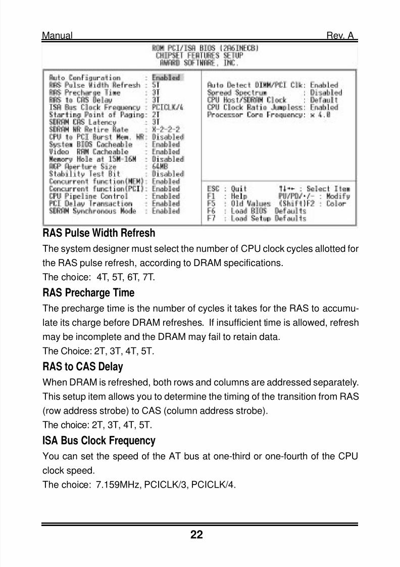
RAS Pulse Width Refresh
The system designer must select the number of CPU clock cycles allotted for
the RAS pulse refresh, according to DRAM specifications.
The choice: 4T, 5T, 6T, 7T.
RAS Precharge TimeThe precharge time is the number of cycles it takes for the RAS to accumu-
late its charge before DRAM refreshes. If insufficient time is allowed, refresh
may be incomplete and the DRAM may fail to retain data.
The Choice: 2T, 3T, 4T, 5T.
RAS to CAS Delay
When DRAM is refreshed, both rows and columns are addressed separately.
This setup item allows you to determine the timing of the transition from RAS(row address strobe) to CAS (column address strobe).
The choice: 2T, 3T, 4T, 5T.
ISA Bus Clock Frequency
You can set the speed of the AT bus at one-third or one-fourth of the CPU
clock speed.
The choice: 7.159MHz, PCICLK/3, PCICLK/4.

8/16/2019 celeron mother board.pdf
http://slidepdf.com/reader/full/celeron-mother-boardpdf 23/32
23
Manual Rev. A
Starting Point of Paging
This value controls the start timing of memory paging operations.
The choice: 1T, 2T, 4T, 8T.
SDRAM CAS Latency
When synchronous DRAM is installed, the number of clock cycles of CAS
latency depends on the DRAM timing. Do not reset this field from the default
value specified by the system designer.
The choice: 2T, 3T.
SDRAM WR Retire Rate
The system designer must select the correct timing for data transfers from thewrite buffer to memory, according to DRAM specifications.
The choice: X-1-1-1, X-2-2-2.
CPU to PCI Burst Mem. WR
Select enabled permits PCI burst memory write cycles, for faster performance.
When disabled, performance is slightly slower, but more reliable.
Choices are Enabled, Disabled.
System BIOS CacheableSelecting Enabled allows caching of the system BIOS ROM at F0000h-FFFFFh,
resulting in better system performance. However, if any program writes to this
memory area, a system error may result.
The choice: Enabled, Disabled.
Video BIOS Cacheable
Selecting Enabled allows caching of the system BIOS ROM at C0000h-F7FFFh,
resulting in better system performance. However, if any program writes to this
memory area, a system error may result.
The choice: Enabled, Disabled.
Memory Hole at 15M-16M
You can reserve this area of system memory for ISA adapter ROM. When
this area is reserved, it cannot be cached. The user information of peripherals
that need to use this area of system memory usually discusses their memory
requirements.The choice: Enabled, Disabled.

8/16/2019 celeron mother board.pdf
http://slidepdf.com/reader/full/celeron-mother-boardpdf 24/32
24
Manual Rev. A
AGP Aperture Size
Select the size of the Accelerated Graphics Port (AGP) aperture. The aper-
ture is a portion of the PCI memory address range dedicated for graphics
memory address space. Host cycles that hit the aperture range are forwarded
to the AGP without any translation. See www.agpforum.org for APG informa-
tion. The choice: 4 MB, 8MB, 16 MB, 32 MB, 64 MB, 128 MB, 256MB.
Concurrent Function [MEM]
When enabled, CPU access memory cycles and PCI masters access memory
cycles can be concurrently issued onto host bus and PCI bus, respectively,
and then the memory access cycles will be rearranged by SiS620 to memory
sequentially. When disabled, either CPU or PCI masters starts memory ac-cess cycle will block the other one’s cycle until the current cycle is finished.
The choice: Enabled, Disabled.
Concurrent Function [PCI]
When this bit is enabled, CPU access PCI bus cycle and PCI masters access
memory cycles can be concurrently issued onto host bus and PCI bus, re-
spectively. By doing this, these cycles will be forwarded to PCI bus and memory
bus at the same time. When disabled, either one of these two kinds of cycleswill block the other until the current cycle is finished.
The choice: Enabled, Disabled.
CPU Pipeline Control
Enable/disable the CPU pipeline control. The choice: Enabled, Disabled.
PCI Delay Transaction
The chipset has an embedded 32-bit posted write buffer to support delay trans-
actions cycles. Select Enabled to support compliance with PCI specification
version 2.1. The choice: Enabled, Disabled.
CPU Clock Ration Jumpless
Enable/disable the CPU Clock ration control. The choice: Enabled, Disabled.
Processor Core Frequency
Select CPU Clock Ratio.

8/16/2019 celeron mother board.pdf
http://slidepdf.com/reader/full/celeron-mother-boardpdf 25/32
25
Manual Rev. A
ACPI function
Select Enabled if your system has an ACPI function. The choice:Enabled, Disabled.
Power Management
This option allows you to select the type (or degree) of power saving
for Doze, Standby, and Suspend modes. See the section PM Timers
for a brief description of each mode. The following describes each power
management mode:
Disable No power management. Disables all four modes
Min. Power Saving Minimum power management.
Max. Power Saving Maximum power management
User Defined Allows you to set each mode individually.

8/16/2019 celeron mother board.pdf
http://slidepdf.com/reader/full/celeron-mother-boardpdf 26/32
26
Manual Rev. A
PM Control by APM
When enabled, an Advanced Power Management device will be acti-vated
to enhance the Max. Power Saving mode and stop the CPU inter-nal
clock. If Advance Power Management (APM) is installed on yoursystem, selecting Yes gives better power savings. If the Max. Power
Saving is not enabled, this will be preset to No .
Video Off Option
When enabled, this feature allows the VGA adapter to operate in a
power saving mode.
Always On Monitor remain on during power savingmodes.
Suspend 2 Off Monitor blanked when systems enters to Suspend mode.
Susp,Stby 2 Off Monitor blanked when the system enters either Suspend
or Standby modes.
All Modes 2 Off Monitor blanked when the system enters any power sav
ing mode.
Video Off Method
This determines the manner in which the monitor is blanked.
V/H SYNC+Blank This selection will cause the system to turn off the vertical
and horizontal synchronization ports
Blank Screen This option only writes blanks to the video buffer.
DPMS Select this option if your monitor supports the Display
Power Management Signaling(DPMS)
Switch Function
You can choose whether or not to permit your system to enter complete Sus-pend mode. Suspend mode offers greater power savings, with a correspond-
ingly longer awakening period..
The choice: Break/Wake, Disabled.
Doze Speed (div by)
Sets the CPUs speed during Doze mode. The speed is reduced to a fraction
of the CPUs normal speed. The divisors range from 1 to 8

8/16/2019 celeron mother board.pdf
http://slidepdf.com/reader/full/celeron-mother-boardpdf 27/32
27
Manual Rev. A
Stdby Speed (div by)
Select a divisor to reduce the CPU speed during Standby mode to a fraction of
the full CPU speed.The speed is reduced to a fraction of the CPU normal
speed. The divisors range from 1 to 8
MODEM Use IRQ
Name the interrupt request (IRQ) line assigned to the modem (if any) on your
system. Activity of the selected IRQ always awakens the system.
The choice: 3, 4, 5, 7, 9, 10, 11, NA.
Hot Key Power Off
Select Enabled if your system has a hot key for soft power off.The choice: Enabled, Disabled.
PM Timers The following four modes are Green PC power saving
functions which are only user configurable when User Defined Power Man-
agement has been selected.
HDD Off After
By default, this item is Disabled, meaning that no matter the mode the rest ofthe system, the hard drive will remain ready. Otherwise, you have a range of
choices from 1 to 15 minutes or Suspend. This means that you can elect to
have your hard disk drive be turned off after a selected number of minutes or
when the rest of the system goes into a Suspend mode.
Doze Mode
When enabled and after the set time of system inactivity, the CPU clock will
run at slower speed while all other devices still operate at full speed.
Standby Mode
When enabled and after the set time of system inactivity, the fixed disk drive
and the video would be shut off while all other devices still operate at full
speed.
Suspend Mode
When enabled and after the set time of system inactivity, all devices except
the CPU will be shut off.

8/16/2019 celeron mother board.pdf
http://slidepdf.com/reader/full/celeron-mother-boardpdf 28/32
28
Manual Rev. A
PM EventsYou may disable activity monitoring of some common I/O
events and interrupt requests so they do not wake up the system. The default
wake-up event is keyboard activity.
HDD Ports ActivityWhen set to On (default), any event occurring at a HDD (serial) port will awaken
a system which has been powered down.
COM Ports Activity
When set to On (default), any event occurring at a hard or floppy drive port will
awaken a system which has been powered down.
LPT Ports ActivityWhen set to On (default), any event occurring at a LPT (printer) port will awaken
a system which has been powered down.
VGA Activity
When set to On (default), any event occurring at VGA will awaken a system
which has been powered down.
Power Button Over Ride
You could press the power button for more than 4 seconds forces the system
to enter the Soft-Off state when the system has hung.
The choice: Soft-Off, Delay 4 Sec.
Ring Power Up Control
When you select Enabled, a signal from ring returns the system to Full On
state. The choice: Enabled, Disabled.
GPIO5 Power Up Control
When you select Enabled, a signal from General Purpose Input 05 returns the
system to Full On state. The choice: Enabled, Disabled.
KB Power ON Password
When you set a password for keyboard, The password you set the keyboard
that returns the system to Full On state.
Power Up by Alarm
When you select Enabled, the following fields appear. They let you set thealarm that returns the system to Full On state.The choice: Enabled, Disabled.
8/16/2019 celeron mother board.pdf
http://slidepdf.com/reader/full/celeron-mother-boardpdf 29/32
29
Manual Rev. A
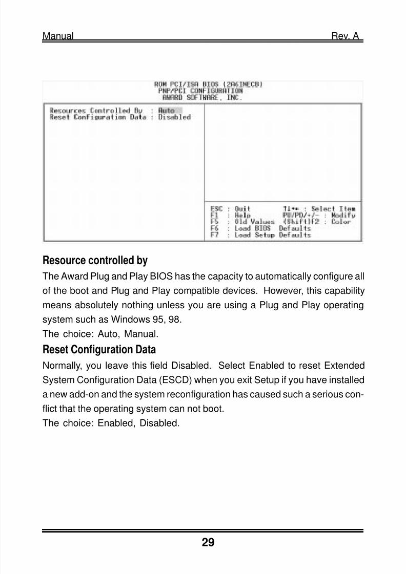
Resource controlled by
The Award Plug and Play BIOS has the capacity to automatically configure all
of the boot and Plug and Play compatible devices. However, this capability
means absolutely nothing unless you are using a Plug and Play operating
system such as Windows 95, 98.
The choice: Auto, Manual.
Reset Configuration Data
Normally, you leave this field Disabled. Select Enabled to reset Extended
System Configuration Data (ESCD) when you exit Setup if you have installed
a new add-on and the system reconfiguration has caused such a serious con-
flict that the operating system can not boot.
The choice: Enabled, Disabled.

8/16/2019 celeron mother board.pdf
http://slidepdf.com/reader/full/celeron-mother-boardpdf 30/32
30
Manual Rev. A
Internal PCI / IDE
This chipset contains an internal PCI IDE interface with support for two IDEchannels. The choice: Primary, Secondary, Both.
IDE Primary Master/Slave PIO
The four IDE PIO (Programmed Input / Output) fields let you set a PIO mode
(0-4) for each of the four IDE devices that the onboard IDE interface supports.
Modes 0 through 4 provide successively increased performance. In Auto
mode, the system automatically determines the best mode for each device.
The choice: Auto, Mode 0, Mode 1, Mode 2, Mode 3, and Mode 4.Primary Master/Slave UltraDMA
UDMA (Ultra DMA) is a DMA data transfer protocol that utilizes ATA com-
mands and the ATA bus to allow DMA commands to transfer data at a maxi-
mum burst rate of 33 MB/s. When you select Auto in the four IDE UDMA
fields (for each of up to four IDE devices that the internal PCI IDE interface
supports), the system automatically determines the optimal data transfer rate
for each IDE device.

8/16/2019 celeron mother board.pdf
http://slidepdf.com/reader/full/celeron-mother-boardpdf 31/32
31
Manual Rev. A
IDE Burst Mode
Selecting Enabled reduces latency between each drive read/write cycle, but
may cause instability in IDE subsystems that cannot support such fast perfor-
mance. If you are getting disk drive errors, try setting this value to Disabled.
This field does not appear when the Internal PCI/IDE field, above, is Disabled.
The choice: Enabled, Disabled.
IDE HDD Block Mode
The chipset contains a PCI IDE interface with support for two IDE channels.
Select Enabled to activate the primary and/or secondary IDE interface. Se-
lect Disabled to deactivate this interface, if you install a primary and/or sec-
ondary add-in IDE interface IDE interface.
Enabled Secondary HDD controller used
Disabled Secondary HDD controller not used.
Onboard FDD Controller
This should be enabled if your system has a floppy disk drive (FDD) installed
on the system board and you wish to use it. Even when so equipped, if you
add a higher performance controller, you will need to disable this feature.The choice: Enabled, Disabled.
Onboard Serial Port 1/Port 2
This item allows you to determine access onboard serial port 1/port 2 control-
ler with which I/O address.
The choice: 3F8/IRQ4, 2E8/IRQ3, 3E8/IRQ4, 2F8/IRQ3, Disabled, Auto.
IR Address Select
Select IR Address. Choices are: Disabled, 2F8H, 3E8H, 2E8H.
IR Mode
Select IR Mode.Choices are: HP SIR, ASKIR.
IR IRQ Select
Select IRQ for IR. Choices are: IRQ3, IRQ4, IRQ10, IRQ11.
Onboard Parallel Port 1
This item allows you to determine access onboard parallel port controller withwhich I/O address. The choice: 3BC/IRQ7, 378/IRQ7, 278/IRQ5, Disabled.

8/16/2019 celeron mother board.pdf
http://slidepdf.com/reader/full/celeron-mother-boardpdf 32/32