cell phone controlled land rover without using micro controller
TRANSCRIPT

5/16/2018 Cell Phone Controlled Land Rover Without Using Micro Controller - slidepdf.com
http://slidepdf.com/reader/full/cell-phone-controlled-land-rover-without-using-micro-controller 1/5
WIRELESS IRRIGATION
Every system is automated in order to face new challenges in the present day situation. Automated
systems have less manual operations, so that the flexibility, reliabilities are high and accurate. Hence
every field prefers automated control systems. For utilization of appliances, the new concept has
been thought to manage them remotely by using GSM, which enables the user to control switching
ON/OFF of agricultural equipments remotely. Just by dialing keypad of remote telephone, from
where you are calling you can perform ON / OFF operation of the appliances. Wireless Control
System for agricultural motors incorporate the global GSM technology which was developed with
the aim of providing economical and easy control solutions using a cell phone. A motor or device
may be switched on/off by phoning the cellular number assigned to the device. This system operates
by sending and receiving SMS. Apart from this, it will prevent the motors from single phasing, dry
run, overload etc. If the said problems are existing, the remote farmer will be getting messageregarding problem details and automatically it will make the motor OFF. It will also indicate the
water level of the reservoir and the temperature of the motor. A potential user only need to use his
cell phone (any type or brand, only contract phones) in order to monitor and control agricultural
field motors.
Irrigating crops with the exactly right amount of water is a tedious task, especially when you have to
walk a long distance to the irrigation pump in the middle of the night to check whether any
problem (fish getting stuck in the intake and as a result the irrigation motor burning or jamming!)
has occured. As I saw my uncles tired of doing the same, I felt there had to be some remote
controlled solution to their problems.
This project “Wireless Remote Motor Starter with Acknowledgement Using Solar Energy Powerfor Agricultural Application” Efficient water management is a major concern in many cropping systemsin semiarid and arid areas. Distributed in-field sensor-based irrigation systems offer a potential solution tosupport site-specific irrigation management that allows producers to maximize their productivity whilesaving water.
In this project, a Robot is controlled by mobile phone using DTMF technique. The Robot isguided by
a mobile phone that makes a call to themobilephoneattached to the robot. In thecourse of a call, if any
button is pressed, a tone corresponding to the button pressed is heardat the other end of thecall. This tone is called DTMF(dual-tone-multiple-frequency).Therobot perceives this
DTMF tone with the he lp of the phonestacke d in the robot . The re ce ive d tone i s
processed by the microcontrol ler with then help of DTMF decoder MT8870. The
decoder decodes the DTMF to ne into its equiva lent binar y digi t and this binary number is
sent to the microcontroller. The microcontroller is programmed to take adecis ion for any given
input and outputs its decision to motor drivers in order to drive themotors in forward
direction or backward direction or turn. The mobile phone that makes acall to mobile
phone stacked in the robot act as a remote. So t his robotic project does no t require the
construction of receiver and transmitter units
5/16/2018 Cell Phone Controlled Land Rover Without Using Micro Controller - slidepdf.com
http://slidepdf.com/reader/full/cell-phone-controlled-land-rover-without-using-micro-controller 2/5
In this project, the robot is controlled by the mobile phone that makes a callto the mobile phone
attached to the robot .In the course of a call, if any button is pressed; atone corresponding to the
button pressed is heared at the other end of the call . This tone iscalled „dual tone -
multiple-frequency‟ (DTMF) tone .The robot perceives the DTMF tone with the help of the
phone stacked in the robot.
The received tone is processed by the 8051 microcontroller with the help of DTMF decoder
MT8870.The decoder decodes the DTMF tone into its equivalent binarydigit and this
binary number is sent to the L293d.The L293d take a decision for any giveninput and
outputs its decision to motor drivers in orde r to drive the motor for forward or backward
motion or a turn.
The mobile that makes a call to the mobile stacked in the robot as a remote.So this simple robotic
project does not require the construction of receiver and transmitter units
.
DTMF s ignali ng is use d for te lephone s ignali ng over the l i ne in voi ce -frequency
band to the call switching center. The version of DTMF used for telephone tonedialing is known as
„Touch Tone‟.DTMF assigns a specific frequency (consisting of two separate tones) toeachkey so that it can easily be identified by the electronics circuit. The signal generated bythe DTMF
encoder is a direct algebraic summation, in real time, of the amplitude of two si ne
(cos ine) waves of d if fe rent f requency, i .e . , press ing „5‟ wil l send a tone madebyadding 1336Hz and 770Hz to the other end of end of the line
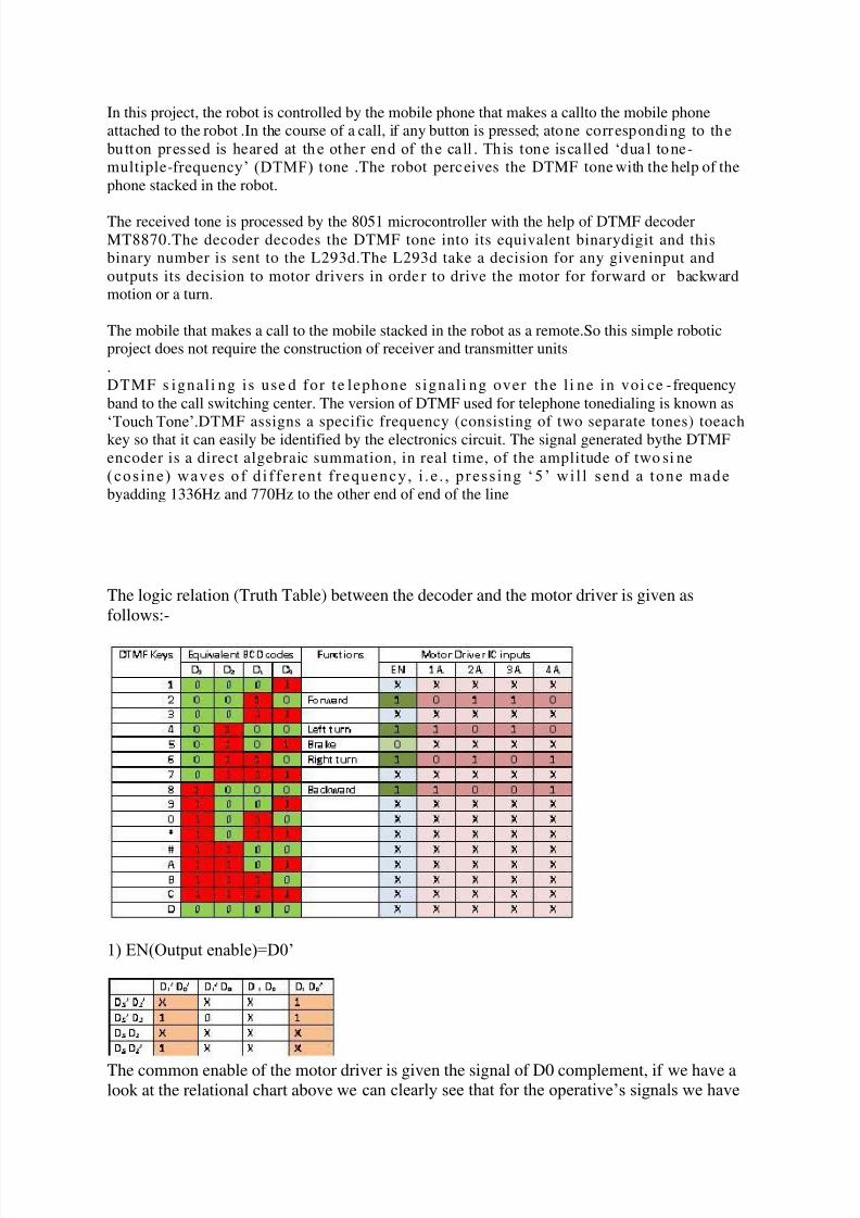
The logic relation (Truth Table) between the decoder and the motor driver is given as
follows:-
1) EN(Output enable)=D0‟
The common enable of the motor driver is given the signal of D0 complement, if we have alook at the relational chart above we can clearly see that for the operative‟s signals we have

5/16/2018 Cell Phone Controlled Land Rover Without Using Micro Controller - slidepdf.com
http://slidepdf.com/reader/full/cell-phone-controlled-land-rover-without-using-micro-controller 3/5
the D0 data line low, which needs to be high and for the brake it should be low as it will stop
all the function of the motor driver bringing the rover to a halt.
2) 1A=D1‟
The first driver signal to the motor driver is the complement of data line D1.
3) 2A=D1
The second driver signal to the motor driver is direct signal of data line D1.
4) 3A=D2‟D1+D2D1‟=D2?D1
The third driver signal to the motor driver is the X-OR signal of the data lines D2 and D 1.
5) 4A=D2‟D1‟+D2D1=( D2?D1)‟
The forth driver signal to the motor driver is the complement of the X-OR signal of the data
lines D2 and D1.
The above K-Map(s) shows and derives the logic relation for each individual input of the
motor drive.
Now, with all the circuit complete, let‟s talk about the interface between different parts. Themost common problem I faced was “How to couple the DTMF signal with the circuit?”, well
the answer was quite simple but it took me a little longer to understand. The simplest thing
you can do is to get a 3.5mm (or 2.5mm, which ever suits you) audio jack (male part) solder a
long enough wire on to it and attach the other open end with the circuit.

5/16/2018 Cell Phone Controlled Land Rover Without Using Micro Controller - slidepdf.com
http://slidepdf.com/reader/full/cell-phone-controlled-land-rover-without-using-micro-controller 4/5
Figure2. 3.5mm male audio jack parts
Connect the wire from signal out pin(s) to the input end of the coupling capacitor in the
circuit (where it reads input from headset), and ground wire of the jack to the circuit ground.
Figure3. Output (female jack) for 3.5mm audio jack from the cell phone
Do not use the audio transmitter enhancements of the cell phone for connecting the jack; use
a cell phone which has the female jack embedded in it (like the one shown in the picture).

5/16/2018 Cell Phone Controlled Land Rover Without Using Micro Controller - slidepdf.com
http://slidepdf.com/reader/full/cell-phone-controlled-land-rover-without-using-micro-controller 5/5
Figure1. Circuit of the land rover
In the above circuit four ICs have been used:-
1) HT9170; DTMF tone decoder
2) L293D; comparator motor driver
3) 74HC04; high speed CMOS hex inverter (not gates)
4) 74HC86; high speed CMOS quad-XOR gates
The first IC (HT9170) decodes the DTMF tones to their respective BCD codes. The second
IC (L293D) is a motor driver IC that is capable of handling the direction of motor easily
according to the given logic inputs, this IC can handle up to 18V dc supply without any extra
heat sink and 18V-30V with a heat sink. The other two ICs are logic gate ICs for the logic
circuit between the decoder and the motor driver.
(NOTE: use HC=high speed CMOS ICs only for this circuit other IC would require extra
hardware like pull up resistors, etc.)