cellcorder crt previewer user's guide - vertiv · figure 54. select file/f3 ... ♦ cellcorder...
TRANSCRIPT

Cellcorder CRT Previewer User's Guide
7775 West Oakland Park Blvd Sunrise, FL 33351
Tel: (954) 377-7101 Fax: (954) 377-7042 www.alber.com
4200–040 R2.1


Cellcorder CRT Previewer User's Guide
7775 West Oakland Park Blvd Sunrise, FL 33351
Tel: (954) 377-7101 Fax: (954) 377-7042 www.alber.com
4200–040 R2.1

Table of Contents
4200-040 R2.1 i 7/1/2015
Table of Contents 1 GENERAL PRODUCT DESCRIPTION ............................................. 1
1.1 Safety Information .................................................................... 1 1.1.1 If Questions Come Up ......................................................... 1
1.2 System Requirements .............................................................. 1 1.3 Helpful Reading ........................................................................ 2
2 BAS SOFTWARE INSTALLATION WITH CRT PREVIEWER ......... 2 2.1 Insert BAS/Previewer Installation CD Into PC ....................... 3 2.2 PDF File Program ...................................................................... 3 2.3 Infrared IR Communication Driver BAS USAGE ONLY ........ 4
2.3.1 Determine COM Port For IR BAS USAGE ONLY ............... 5 3 START PREVIEWER SOFTWARE ................................................... 7
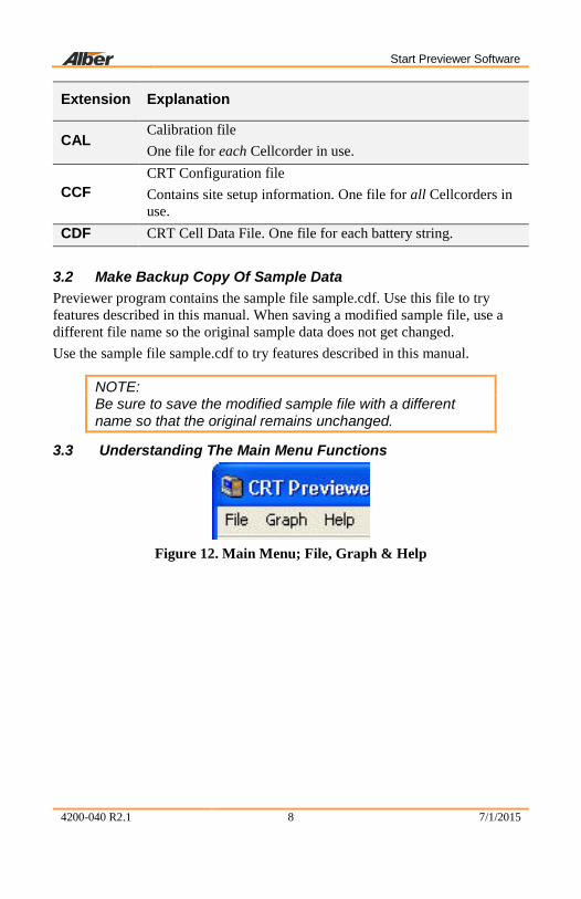
3.1 Explanation Of File Types ........................................................ 7 3.2 Make Backup Copy Of Sample Data ....................................... 8 3.3 Understanding The Main Menu Functions ............................. 8
3.3.1 File ..................................................................................... 10 3.3.2 Graph ................................................................................. 11 3.3.3 Help ................................................................................... 12
3.4 Toolbar ..................................................................................... 13 3.5 Previewer Tabs ....................................................................... 13
3.5.1 General .............................................................................. 13 3.5.2 Tabular Data ...................................................................... 15 3.5.3 Graph ................................................................................. 18 3.5.4 Intertier .............................................................................. 20 3.5.5 Comments ......................................................................... 23
4 THE IMPORTANT CONFIGURATION FILE EDITOR: CCF ........... 23 4.1 Multiple Sites – IMPORTANT ................................................. 24 4.2 General Tab – Configuration File Editor CFE ...................... 25
4.2.1 Model Number/Browse/Battery List Editor Window .......... 28 4.3 Threshold Tab – Configuration Editor .................................. 35 4.4 Test Mode Tab – Configuration Editor ................................. 36
4.4.1 Amp Hour Rating ............................................................... 36 4.4.2 Single Testing .................................................................... 36

Table of Contents
4200-040 R2.1 ii 7/1/2015
4.4.3 Dual Testing ...................................................................... 37 4.4.4 Triple Testing ..................................................................... 37 4.4.5 Quad Testing ..................................................................... 37 4.4.6 Combined Testing ............................................................. 37 4.4.7 Computed Testing ............................................................. 37
5 BEGIN – OPEN A *.CDF OR VIEW CRT BATTERY DATA ........... 38 5.1 To Save Readings/Files (From CRT Manual) ....................... 39 5.2 Memory Card Note .................................................................. 41
6 GENERATING REPORTS............................................................... 42 6.1 Setting Report Options .......................................................... 42
7 EXPORTING DATA ......................................................................... 43 7.1 Export File Type ...................................................................... 44 7.2 Export Destination .................................................................. 44
8 CREATING A DATA SET ................................................................ 47 9 CRT CALIBRATION BACKUP ....................................................... 47 10 CRT CALIBRATION BACKUP .................................................... 48 11 UPGRADE CRT FIRMWARE ...................................................... 49

Table of Figures
4200-040 R2.1 iii 7/1/2015
Table of Figures Figure 1. Insert CD .............................................................................................. 3 Figure 2. Start|Run ............................................................................................... 3 Figure 3. Installing When CD Does Not Auto start ............................................. 3 Figure 4. Previewer Icon ...................................................................................... 3 Figure 5. Installing the PDF Writer ..................................................................... 4 Figure 6. Postscript Interpreter Installation .......................................................... 4 Figure 7. IR Driver Install Window ..................................................................... 5 Figure 8. Select COM Port For IR Communication BAS USAGE ONLY .......... 5 Figure 9. Install IR Driver/BAS USAGE ONLY ................................................. 6 Figure 10. Install IR Driver Later/BAS USAGE ONLY ..................................... 7 Figure 11. Start|Programs|Alber|Alber Battery Analysis| CRT Previewer ........... 7 Figure 12. Main Menu; File, Graph & Help ........................................................ 8 Figure 13. Main Menu File .................................................................................. 9 Figure 14. Main Menu Help ................................................................................. 9 Figure 15. Main Menu Graph .............................................................................. 9 Figure 16. File Menu.......................................................................................... 10 Figure 17. Main Menu Graph ............................................................................ 11 Figure 18. Return To Previous Graph View Esc Key ........................................ 11 Figure 19. Main Menu Help ............................................................................... 12 Figure 20. Help On Help Window And Explanation ......................................... 12 Figure 21. Help About ....................................................................................... 12 Figure 22. Toolbar ............................................................................................. 13 Figure 23. General tab........................................................................................ 14 Figure 24. Tabular Data Tab .............................................................................. 16 Figure 25. Tabular Data Sort Ascending ............................................................ 17 Figure 26. Tabular Data Sort Descending .......................................................... 17 Figure 27. Cell Data Editor ................................................................................ 18 Figure 28. Graph Tab ......................................................................................... 19 Figure 29. Select Parameter ............................................................................... 20 Figure 30. Cell Data Box ................................................................................... 20 Figure 31. Intertier Tab ...................................................................................... 21 Figure 32. Comments Tab .................................................................................. 23 Figure 33. Previewer Icon .................................................................................. 24 Figure 34. File|Configuration Editor .................................................................. 24 Figure 35. Configuration Editor ......................................................................... 25 Figure 36. Configuration Editor|File|New| Save|Import|Exit ............................. 27 Figure 37. Error Message ................................................................................... 27 Figure 38. Configuration Editor|Edit|Delete|Sort ............................................... 27 Figure 39. Configuration File Editor .................................................................. 28 Figure 40. Battery List Editor ............................................................................ 29

Table of Figures
4200-040 R2.1 iv 7/1/2015
Figure 41. Import From Another Battery List File............................................. 29 Figure 42. Helpful Battlist.blf ............................................................................ 30 Figure 43. www.alber.com Baseline Resistance Data/Battlist.blf...................... 30 Figure 44. BLF On The Website ........................................................................ 31 Figure 45. File Download BLF .......................................................................... 32 Figure 46. C:\Program Files\alber\Alber Battery Analysis ................................ 32 Figure 47. Imported Battlist.blf.......................................................................... 33 Figure 48. File| New Battery .............................................................................. 33 Figure 49. Battery List Editor New Battery ....................................................... 34 Figure 50. Threshold Tab Configuration File Editor ......................................... 35 Figure 51. Configuration Editor Test Mode Tab................................................ 36 Figure 52. Saving The CCF ............................................................................... 38 Figure 53. Enter File Name ................................................................................ 39 Figure 54. Select File/F3 .................................................................................... 39 Figure 55. WARNING Data Will Be Lost ......................................................... 39 Figure 56. File Exists Overwrite WARNING .................................................... 40 Figure 57. File|Open .......................................................................................... 40 Figure 58. Open *.CDF in C:\Program Files\Alber\Alber Battery
Analysis\CellCorder CDF Files ....................................................... 41 Figure 59. Open CDF On USB Flash Hard Drive Or Smart Media Card ........ 41 Figure 60. Report Option ................................................................................... 42 Figure 61. Export Options .................................................................................. 43 Figure 62. Export File Options .......................................................................... 44 Figure 63. Export Text ....................................................................................... 45 Figure 64. Select Configuration ......................................................................... 47

General Product Description
4200-040 R2.1 1 7/1/2015
1 General Product Description The Albér CRT Previewer software program allows the user to view the data file, .CDF, created by the CRT and stored on the USB device and/or the Smart Media memory card. Unlike the Battery Analysis System BAS program, where the user can continually build battery files by appending new sets of readings, Previewer only allows the user to view one set of readings at a time and print them. Previewer can do the following: ♦ Display data in bar graph and tabular formats. ♦ Modify data and save the file. ♦ Manually create a battery file by entering data from another source and
saving the file. ♦ Create site setup information for the CRT. ♦ Update Cellcorder CRT firmware. Previewer interfaces with the CRT Cellcorders only. The key differences are: ♦ The CRT–300 has Smart Media memory card capability and ♦ The CRT–400 has a USB port. 1.1 Safety Information It is extremely important to read and to understand the safety precautions outlined in the Legal Safety section of the CRT User's Guides and those printed elsewhere in this manual and/or corresponding manuals before using the Cellcorder and the software. Proper installation, use and testing are essential to the correct functioning of the software and the Cellcorder. 1.1.1 If Questions Come Up If the user has questions, contact Albér at 954–377-7101 or fax 954–377-7042; request Albér CRT Previewer software program or Cellcorder assistance. 1.2 System Requirements The following are the minimum system requirements for the CRT Previewer software operation. ♦ Version 2.01A01or later firmware for the CRT–400 Cellcorder, ♦ Version 1.00A25 or later firmware for the CRT–300 Cellcorder ♦ Microsoft Windows®– 2000 or XP. ♦ Pentium4™ 1GHz or higher microprocessor. ♦ 128M of memory for Windows 2000, 256M for Windows XP. ♦ 150M of hard disk space for program installation. 1G of space for data
storage.

BAS Software Installation With CRT PREVIEWER
4200-040 R2.1 2 7/1/2015
♦ CD|DVD drive. ♦ USB port on computer for transferring data via USB flash drive. 1.3 Helpful Reading It is a good idea to read through the following manuals before using the CRT and Albér CRT Previewer software program. ♦ Cellcorder CRT Previewer User's Guide, pn 4200–040 ♦ Battery Analysis System User’s Guide, pn 4200–002 ♦ Cellcorder CRT User’s Guide, pn 4200–038, pn 4200–070 ♦ USB device manufacturer’s instructions. Belkin Components, Smart Media
or other instructions. ♦ Uninterruptible Power Supply UPS manufacturer’s instruction manual, if a
UPS is used. 2 BAS Software Installation With CRT PREVIEWER The Albér CRT Previewer software program is compatible with CRTs, Version 1.00A25 or later, and is distributed on one CD. Before installation, close all other programs. To install the program, insert the CD into the computer and select Start|Run from the Windows desktop. From the Run window, type d:\setup (or other drive) to start the installation, then follow the on–screen instructions. After installation, an icon shortcut appears on the desktop. During installation, the options to install the following are available: ♦ a PDF writer,
NOTE: If Adobe Writer software is already installed on the pc, then do not install the PDF writer made available with this software.
♦ an IR driver, and
NOTE: IR communication is done with the BAS software only.
♦ a sample database.

BAS Software Installation With CRT PREVIEWER
4200-040 R2.1 3 7/1/2015
2.1 Insert BAS/Previewer Installation CD Into PC
Before BAS software installation, close all other programs. To install the program, insert the CD into the computer. The CD is equipped to auto start to install the program.
Figure 1. Insert CD
If the CD does not auto start, select Start|Run from the Windows task bar.
Figure 2. Start|Run From the Run window, type d:\setup (or other drive letter that corresponds to where the DVD|CD is), or select Browse to find the DVD|DC drive, then follow the instructions.
Figure 3. Installing When CD Does Not Auto start
After installation, an icon appears on the desktop.
Figure 4. Previewer Icon 2.2 PDF File Program DocudeskIf a program such as Adobe Acrobat® is not installed on the pc and the user wants to create reports in PDF format, the user may install a trial version of the Docudesk™ PDF writer during software installation. After 15 trial uses, the user may purchase the writer program from Docudesk: www.docudesk.com.

BAS Software Installation With CRT PREVIEWER
4200-040 R2.1 4 7/1/2015
Figure 5. Installing the PDF Writer
When installing the Docudesk PDF writer, a window may indicate that the user needs a Postscript interpreter. When the user selects Next>, the Ghostscript program installs.
Figure 6. Postscript Interpreter Installation
NOTE: To install the PDF writer later, browse the BAS CD to the Docudesk PDF folder and click the deskPDF25Std–Setup.exe install file.
2.3 Infrared IR Communication Driver BAS USAGE ONLY
NOTE: Only the BAS communicates via IR. INSTALLATION STEPS ARE PROVIDED HERE IN CASE THE PREVIEWER MANUAL IS FOLLOWED FIRST.

BAS Software Installation With CRT PREVIEWER
4200-040 R2.1 5 7/1/2015
Once the user has finished installing the PDF writer and interpreter, a window will ask the user to install the IR driver.
Figure 7. IR Driver Install Window
If the user wants to communicate by IR and is using Windows 2000 or XP and the computer has an IR port, then install the IRComm2K IR port driver to allow the computer to communicate via IR with the BAS program. If the user attempts to install the IR driver on a computer with no IR port, the user will receive the warning, “There is no infrared adaptor installed on this system.” The user may continue with driver installation, but the driver will not do anything until an IR adaptor is installed. 2.3.1 Determine COM Port For IR BAS USAGE ONLY During IR installation, select a COM port for IR Communication Driver.
NOTE: Ports (in use) are not available for IR Communication and the installation wizard will indicate those ports that are in use. Previewer will not recognize IR communication.
Figure 8. Select COM Port For IR Communication BAS USAGE ONLY

BAS Software Installation With CRT PREVIEWER
4200-040 R2.1 6 7/1/2015
Figure 9. Install IR Driver/BAS USAGE ONLY
Once the user has selected the port, the IRComm2K Setup window appears. At this window, the user may choose to install the IR driver or exit without installing. program
NOTE: To install the IR driver later, go to My computer and access the program files. The Program Files are kept on the C: drive. Go to C:\Program Files\alber\Alber Battery Analysis\IR driver, select Setup.exe, and follow the instructions.

Start Previewer Software
4200-040 R2.1 7 7/1/2015
Figure 10. Install IR Driver Later/BAS USAGE ONLY
3 Start Previewer Software To start the Previewer software program, double–click the Previewer icon on the desktop or select Start|Programs|Alber|Alber Battery Analysis| CRT Previewer from the Task bar. Previewer opens and the General tab appears. Each toolbar button along the top of the program window displays a hint when the cursor is over it.
Figure 11. Start|Programs|Alber|Alber Battery Analysis| CRT Previewer
3.1 Explanation Of File Types Several file extensions are used in the Cellcorder BAS and Previewer programs. These extensions are associated as follows: types
Extension Explanation
ADF Accumulated Data File Used primarily within the BAS software. Contains sets of readings or imported data or CDFs.
BLF
Battery List File Used by the Battery List Editor under the Browse button on the Configuration Editor. The BLF file is created from battery model data entered by the user.
Start Previewer Software
4200-040 R2.1 8 7/1/2015
Extension Explanation
CAL Calibration file One file for each Cellcorder in use.
CCF CRT Configuration file Contains site setup information. One file for all Cellcorders in use.
CDF CRT Cell Data File. One file for each battery string.
3.2 Make Backup Copy Of Sample Data Previewer program contains the sample file sample.cdf. Use this file to try features described in this manual. When saving a modified sample file, use a different file name so the original sample data does not get changed. Use the sample file sample.cdf to try features described in this manual.
NOTE: Be sure to save the modified sample file with a different name so that the original remains unchanged.
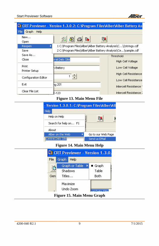
3.3 Understanding The Main Menu Functions
Figure 12. Main Menu; File, Graph & Help
Start Previewer Software
4200-040 R2.1 9 7/1/2015
Figure 13. Main Menu File
Figure 14. Main Menu Help
Figure 15. Main Menu Graph

Start Previewer Software
4200-040 R2.1 10 7/1/2015
3.3.1 File
NOTE: A few File Menu options have no toolbar button equivalents.
Figure 16. File Menu
File|New Opens the Select Configuration window. Use to manually create a battery file. Refer to Creating a Data Set.
File|Open Opens a list of Cellcorder .CDF data files in the Cellcorder .CDFs subdirectory. Refer to Main Menu.
File|Reopen Displays a list of recently opened files. Click a file name to open it.
File|Save As Displays a list of ..CDFs in the .CDFs subdirectory. Save the file as a..CDF with an existing or new name.
File|Close Closes the currently open file.
File|Print Opens the Report Option window and then the Print Preview before printing. Refer to Setting Report Options.
File|Printer Setup Selects the printer and paper orientation. File|Configuration Editor
Displays the Configuration File Editor pages. Refer to Configuration File Editor.
File|Exit Closes Previewer program. File|Clear File List
Clears the list of recently opened files that appears when File|Reopen is selected.

Start Previewer Software
4200-040 R2.1 11 7/1/2015
3.3.2 Graph
Figure 17. Main Menu Graph
Graph| Graph or Table
The user may choose to view only the graph of the data, or the table populated with cell data or Both.
Graph| Shadows
Adds/removes shadows to the bars in the graph.
Graph| Titles
Adds and/or changes the Graph’s Title. Customizes the graph title and stores it in the .CDF. When found in a configuration file during report generation, the customized title appears on each graph in the report. Otherwise, the user–defined report title appears.
Graph| Maximize
Select to maximize the graph for better viewing.Use the Esc key on the keyboard or click in the upper left corner to return to regular viewing.
Figure 18. Return To Previous Graph View Esc Key
Undo Zoom
To zoom in on an area in the graph, select the Ctrl key on the keyboard and hold down the button on the mouse and move over the area to be enlarged. Use Undo Zoom to go back to the previous view. Another way to zoom in on a portion of the bar graph, place the mouse and program cursor on the graph, hold the left mouse button down, and drag across the cells of interest. The cursor changes to a magnifying glass when selecting a valid region. Release the mouse button to complete the zooming. Select Undo Zoom on the Graph menu to return to original size.
Start Previewer Software
4200-040 R2.1 12 7/1/2015
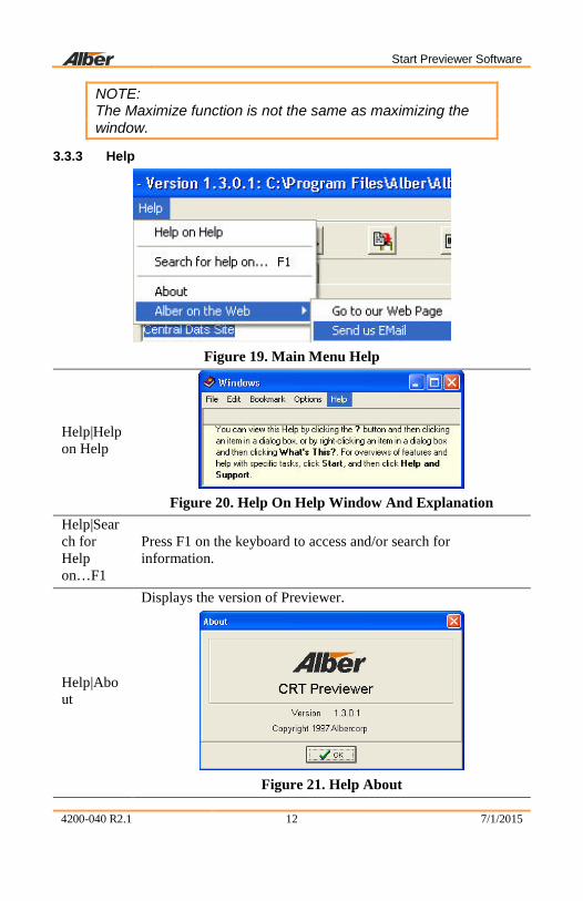
NOTE: The Maximize function is not the same as maximizing the window.
3.3.3 Help
Figure 19. Main Menu Help
Help|Help on Help
Figure 20. Help On Help Window And Explanation
Help|Search for Help on…F1
Press F1 on the keyboard to access and/or search for information.
Help|About
Displays the version of Previewer.
Figure 21. Help About

Start Previewer Software
4200-040 R2.1 13 7/1/2015
Help| Albér on the web
The user can send an email to Albér or go to the website for more information.
3.4 Toolbar
Figure 22. Toolbar
The Toolbar provides access to all program features. Some toolbar buttons are not active until certain actions occur, such as opening a battery data file.
Create new data file
Open a file
Save current file
Close .CDF
Select parameters
Edit values of cell
Export graph
Transfer data to BAS Import CDF into ADF
3.5 Previewer Tabs When Previewer starts, the General tab appears. To open a file, click the Open
File Open button or select File|Open from the Main Menu. Previewer opens Cellcorder CRT .CDFs. The Cellcorder CLC–200 data files may be uploaded and saved as a .CDF. Battery data can be edited on the General, Intertier, and Comments Tabs. After opening a file, click a tab to display. Changes are not saved to the battery file until a Save is performed. Usually save files to the default Cellcorder .CDFs subdirectory. 3.5.1 General Use the General tab to edit site information such as location, battery, and string names, model number, and dates, and set temperature, frequency, and date format. Changing the number of cells, thresholds, temperature units, charger frequency, and date format changes the battery data file contents.

Start Previewer Software
4200-040 R2.1 14 7/1/2015
Figure 23. General tab
The bottom left of the page displays Overall Voltage OV and Average Cell Voltage, Resistance, Temperature, Specific Gravity SG, and Intercell Resistance. This data cannot be changed. These values are not read from the .CDF, but are calculated from the data.
Location Name, Battery Name, String Name
Edit location name, battery name, and string name in these boxes.
Model Number Edit the model number of the battery.
Number of Cells
This setting normally is set to the number of cells in the battery, but may be used to limit or expand the number of cells shown on charts or graphs. Change the Number of Cells setting with caution.

Start Previewer Software
4200-040 R2.1 15 7/1/2015
CAUTION:
The Number of Cells setting affects most displays of battery data, including graphs, reports, and calculations. However, changes to this setting do not affect the actual cell data in the file. No data is lost by reducing the number of cells; the excess cell values simply become unavailable to the program until the Number of Cells is changed to its original value.
Install Date Edit the date the battery was installed.
Read Date Indicates the date of the data being displayed. To change, type a new date or click the date field drop–down button and click on the calendar.
Thresholds
Threshold values for voltage, resistance, temperature and SG may be changed in this area. The Graph Tab bar graph colors change when thresholds are changed. The colors indicate cells are within or exceeding minimum or maximum limits.
Temperature Units
Changing the Temperature Units from Fahrenheit to Celsius converts temperatures to Celsius throughout the program. Changing the temperature scale does not affect the values of data in the file, but only the way the values are indicated.
Charger Frequency Select 50Hz or 60Hz to filter the ripple frequency.
Date Format Select U.S. (mm/dd/yyyy), Europe (dd/mm/yyyy) or China (yyyy/mm/dd) date format.
3.5.2 Tabular Data The Tabular Data Tab displays values for all cells with data. When data is available, columns display cell number, cell voltage, internal resistance, intercell R1 to R4 resistance, temperature, and specific gravity.

Start Previewer Software
4200-040 R2.1 16 7/1/2015
Figure 24. Tabular Data Tab
Data is arranged in a list view, which displays record oriented data in rows and columns. Each column represents a field of a record, and each row represents one record. Click a column header to sort on that column. Click the same header again to reverse the order. A triangle in the header of the selected column points up when sorted in ascending order or down for descending.

Start Previewer Software
4200-040 R2.1 17 7/1/2015
Figure 25. Tabular Data Sort
Ascending
Figure 26. Tabular Data Sort
Descending To re–arrange column order, click a column header and hold the mouse button down, then drag the header onto another column header. Release the mouse button to place the column at that position. To change column width, drag the dividing line between two column headers left or right. 3.5.2.1 Editing Cell Data To open the Cell Data Editor to change data on the Tabular Data Tab, click the
Edit Values button , or double–click a cell number or row on the Tabular Data Tab. The editor indexes to the cell number or row clicked. Use the mouse, Tab or Arrow keys to highlight data to be changed. When editing is complete, click OK to save the changes.

Start Previewer Software
4200-040 R2.1 18 7/1/2015
Figure 27. Cell Data Editor
3.5.3 Graph The Graph Tab displays battery file data in graph and/or table format. The graph can be customized, printed and exported for report generation. Menu items are described below.

Start Previewer Software
4200-040 R2.1 19 7/1/2015
Figure 28. Graph Tab
3.5.3.1 Graph Parameters The Select Parameters window allows the user to select which parameters appear on the Tabular Data and Graph Tabs.
To display, click the Select Parameters button .

Start Previewer Software
4200-040 R2.1 20 7/1/2015
Figure 29. Select Parameter
Check the boxes to cause parameters to display on the Tabular Data or Graph Tabs, then click OK. 3.5.3.2 Bar Graph Cell Data To display text data for a particular cell in the bar graph, enlarge the area of interest on the graph, then click on a bar graph. The Cell Data window appears.
Figure 30. Cell Data Box
The Cell Data window displays the cell number clicked and the cell voltage, internal resistance, intercell resistance, temperature and gravity when data is available. The bold value indicates the portion of the bar graph clicked. For example, if the Intercell Resistance 3 bar was clicked, the value for Intercell Resistance 3 is bold. 3.5.4 Intertier The Intertier Tab lets the user set locations of intertiers, either manually or automatically.

Start Previewer Software
4200-040 R2.1 21 7/1/2015
Figure 31. Intertier Tab
3.5.4.1 Intertier Configuration The user may mark battery cells as intertier cells to indicate they are on the boundary of an intertier connection. By convention, only the cell with the lower cell number is marked. For example, if Cell 10, the last cell of one row of cells, is connected to Cell 11, the first cell of the next row of cells, only mark Cell 10 as an intertier cell. Intertier configuration affects how intercell resistances are calculated. The program ignores intertier cells when calculating high, average, and low intercell resistances for a series of cells because intertier cells have much higher intercell resistances than other cells. To configure intertier cells, open the battery file. Verify the battery has been configured with the correct number of cells on the General tab. On the Intertier Tab, Available Cells lists cells not designated as intertier cells. When first displayed, the list contains all the cells for the battery, since none are yet marked. Current Configuration lists cells marked as intertier cells. The Intertier Configuration Wizard is to the right.

Start Previewer Software
4200-040 R2.1 22 7/1/2015
There are three ways to create an intertier configuration:
Method 1
Select one or more cells in either list, then click the Add, Remove or All button. Add moves selected cells from Available Cells to Current Configuration. Remove moves selected cells from Configuration to Available. All moves all cells from Configuration to Available. To select multiple cells, hold the Ctrl key down and click each cell. To select a group of cells, click the first cell in the group, hold Shift down, then click the last cell in the group.
Method 2 Select one or more cells in either list, then drag the selection onto the other list.
Method 3
Use the Configuration Wizard to automatically create an intertier configuration. First, click All, if necessary, to clear the current configuration. On the Wizard, fill in the box next to the First intertier follows cell number and the Set an intertier after every nn cells box. The Example area shows the start of the sequence. Click Configure to display the results in the Current Configuration list. The list may be edited, if needed, by using the Add or Remove buttons.
As an example, if a 24 cell battery has intertier cells at 6, 12 and 18, enter 6 in both edit boxes to indicate an intertier every six cells, beginning with cell number 6.

The IMPORTANT Configuration File Editor: CCF
4200-040 R2.1 23 7/1/2015
3.5.5 Comments
Figure 32. Comments Tab
Use the Comments Tab text editor for typing comments. For example, a battery maintenance log might show the date and type of readings taken, or when a cell was replaced or connectors cleaned. The user can copy text on this page to the clipboard; right click the comments area to open the edit menu. 4 The IMPORTANT Configuration File Editor: CCF This section describes how to create and edit the configuration file using the Configuration Editor in Previewer. To use the Cellcorder to create the file, refer to Setting Up and Editing a Site in the Cellcorder manual.
NOTE: Previewer has a General tab with a Threshold area displayed in the bottom left; the Configuration Editor has a General tab and a Threshold tab.
To edit or create a .CCF/configuration file, click File|Configuration Editor. The editor opens the CCF or, if none exists, indicates Site 0 of 0. To edit a site, select the Location, Battery and String Names from drop down lists or, to add a new site or create a CCF if none exists, click New and type data. If a configuration site is opened in Previewer, changes made and saved to the General tab or Threshold area are reflected in the CCF on the Configuration Editor General tab and Threshold Page.

The IMPORTANT Configuration File Editor: CCF
4200-040 R2.1 24 7/1/2015
NOTE: It is highly recommended to set up configurations/sites prior to using the CRT/BAS/Previewer for the first time for future ease of use. To use the Cellcorder to create the file, refer to the Cellcorder User’s Guide. The CCF is the file that keeps all site information, it is important not to overwrite this file and it is important to keep a backup of this file.
This section describes how to use the Previewer Configuration Editor to create and edit the configuration file, CCF.
Start Previewer by double–clicking the icon on the desktop.
Figure 33. Previewer Icon
Select File|Configuration Editor from the Main Menu.
Figure 34. File|Configuration Editor
4.1 Multiple Sites – IMPORTANT If more than one Cellcorder is used to read data at multiple sites, and one computer is capturing all the data, the CCF must originate and be maintained using the Configuration Editor. This avoids having a different CCF on each Cellcorder.

The IMPORTANT Configuration File Editor: CCF
4200-040 R2.1 25 7/1/2015
NOTES: Once the CCF or BLF has been edited and changed, keep backup copies for future reference. Any site created on the CRT and then linked to a CDF data file is added to the CCF when the Previewer/BAS program opens the CDF.
4.2 General Tab – Configuration File Editor CFE The Configuration File Editor opens the CCF or, if none exists, indicates Site 0 of 0 on the General tab. To create a CCF if none exists, start completing the text boxes provided with the required information; Location Name, Battery Name, Number of Strings, String Name, Model Number, Number of Cells, Install Date, Charger Frequency, and Cell Voltage Range.
Figure 35. Configuration Editor

The IMPORTANT Configuration File Editor: CCF
4200-040 R2.1 26 7/1/2015
The following table is provided for entry explanation:
Site No. Indicates what site is being displayed, as determined by the location, battery and string names selected. :
Location Name Type the location name of the battery installation.
Battery Name
Assign a unique name to the battery. The user cannot have two identical battery names under the same location name. Selecting different batteries changes choices in the String box.
Number of Strings
Select the number of strings that are associated with the battery.
String Name Type a name for each string. The user cannot have two identical string names under the same battery name.
Model Number Type the model number of the cells or click to open the Battery List Editor. Refer to next section.
Number of Cells The default total number of cells is 256. Normally, type the total number of cells in the string. The user may change the number for custom configurations.
Install Date Type the battery installation date.
Charger Frequency
Selecting 50Hz or 60Hz lets the Cellcorder reject 50Hz or 60Hz ripple and harmonics.
Cell Voltage Range Select the voltage range of the cells being tested.

The IMPORTANT Configuration File Editor: CCF
4200-040 R2.1 27 7/1/2015
NOTE: Date and Time Format are automatically determined from the user's pc setup. The user cannot have two identical battery names under the same location name. Selecting different batteries changes the available strings on the String window. The user cannot have two identical string names under the same battery name.
Figure 36. Configuration
Editor|File|New| Save|Import|Exit
File|New begins a NEW CCF. File|Save saves the CCF. Use File|Import on the Configuration Editor to add sites from another CCF. If an existing battery/string name exists, an Error message window opens, select to go back and enter different information.
Figure 37. Error Message
Figure 38. Configuration Editor|Edit|Delete|Sort
Edit|Delete will delete the entire Site No#. Edit|Sort sorts the CCF on location, battery and string names.

The IMPORTANT Configuration File Editor: CCF
4200-040 R2.1 28 7/1/2015
Figure 39. Configuration File Editor
4.2.1 Model Number/Browse/Battery List Editor Window From the General Tab within the Configuration File Editor, the user may
click to select from a variety of previously defined battery types within the file BattList.blf. The Battery List Editor allows the user to transfer preset parameters to the Threshold and Type tabs as well as entering the Battery's Model Number.
NOTE: Data from the Battery List Editor is saved into the BLF file. To save and transfer the parameters to the Threshold and Type windows, click then . The user must still complete the General tab.

The IMPORTANT Configuration File Editor: CCF
4200-040 R2.1 29 7/1/2015
Click to remove a selected battery manufacturer and model setup from the Battery List Editor window.
Once
has been selected, the Battery List Editor window appears.
Figure 40. Battery List Editor
Select File from the Battery List Editor main menu. At this time, the user may enter a New Battery and its information. Alternatively, as in this scenario, the user has decided to import the already provided Battery List File by selecting Import From Another Battery List File.
Figure 41. Import From Another Battery
List File Save and Exit are self–explanatory options here too.

The IMPORTANT Configuration File Editor: CCF
4200-040 R2.1 30 7/1/2015
Locate the 'newest' BattList.blf file provided with the BAS setup CD/or edited by the user. Highlight the file and press
.
Figure 42. Helpful Battlist.blf
NOTE: It is important to track all changes made in the Battlist.blf in case the file becomes corrupt. The user may always download the original Battlist.blf file from www.alber.com. The set of instructions are for recovering the Battlist.blf file from the web and may be skipped by the user. This file was developed to aid the user and to help populate typical values for typical batteries used in the field.
Figure 43. www.alber.com Baseline Resistance Data/Battlist.blf

The IMPORTANT Configuration File Editor: CCF
4200-040 R2.1 31 7/1/2015
Figure 44. BLF On The Website

The IMPORTANT Configuration File Editor: CCF
4200-040 R2.1 32 7/1/2015
Figure 45. File Download BLF
Figure 46. C:\Program Files\alber\Alber Battery Analysis
Select and navigate to C:\Program Files\alber\Alber Battery Analysis or where the user may have program files stored to save the BattList.blf for importing into the software program later.

The IMPORTANT Configuration File Editor: CCF
4200-040 R2.1 33 7/1/2015
The BattList.blf usually populates the Battery List Editor so the user can choose the Manufacturer, Model Number, Cell Voltage Range and enter all other necessary information for this battery. When the BLF is downloaded from the web, it may be necessary to import the BLF file as in the previous instructions.
Figure 47. Imported Battlist.blf
NOTE TO TRANSFER PARAMETERS: Select a Manufacturer and Model Number from the drop–down lists now populated by the Battery List File and click
to transfer the provided information to the Threshold and Type tabs.
Figure 48. File| New
Battery
Add a New Battery – To add parameters for a new battery manufacturer and model, click File|New Battery from the main menu.

The IMPORTANT Configuration File Editor: CCF
4200-040 R2.1 34 7/1/2015
Type in Manufacturer, Model Number, Voltages, resistances, temperature, specific gravity, cell voltage range, amp hours, and intercell type. In the Base Line box, type the typical resistance of a known good cell for the type of battery.
Click to save the parameters for the new make and model in the list.
Figure 49. Battery List Editor New Battery
NOTE: Data from the Battery List Editor is saved into the BLF file. To save and transfer the parameters to the Threshold and Type windows, click then .
Click to remove a selected battery manufacturer and model setup from the Battery List Editor window.

The IMPORTANT Configuration File Editor: CCF
4200-040 R2.1 35 7/1/2015
4.3 Threshold Tab – Configuration Editor
Data in the Threshold tab configures the Cellcorder unit. Use the Threshold tab to set low and high limits for voltage, resistance, temperature, and SG. Select the Temperature Unit in C for Celsius or F for Fahrenheit.
Figure 50. Threshold Tab Configuration File Editor
NOTES: Threshold levels cannot be set to zero. During testing, two beeps on the Cellcorder indicate limits are exceeded. The Threshold Tab is not used for changing the display colors or threshold levels. The Temperature Unit function, C or F is used for CRT setup and does not convert temperatures from F to C or C to F.

The IMPORTANT Configuration File Editor: CCF
4200-040 R2.1 36 7/1/2015
4.4 Test Mode Tab – Configuration Editor
Use the Test Mode tab to set the Amp Hour Rating and Intercell Type.
Figure 51. Configuration Editor Test Mode Tab
4.4.1 Amp Hour Rating Select the battery size, smaller or larger than 1000 Ah. This sets the length of time the Cellcorder applies a load during a load test.
NOTE: Select how many Intercell Connections IC per cell will be read (one to four) by choosing Single, Dual, Triple or Quad, or select Combined or Computed.
4.4.2 Single Testing If the user is testing batteries with 2 two terminals and the batteries are connected in series.

The IMPORTANT Configuration File Editor: CCF
4200-040 R2.1 37 7/1/2015
4.4.3 Dual Testing If the user is testing batteries with 4 four terminals and the batteries are connected in series. 4.4.4 Triple Testing If the user is testing batteries with 6 six terminals and the batteries are connected in series or if 3 three positive terminals are connected together and the 3 three negatives are connected together. 4.4.5 Quad Testing If the user is testing batteries when each negative of 3 three negative terminals are connected to each positive of the 3 three positive terminals of the next battery. 4.4.6 Combined Testing Combined testing is done in one–step using only two leads and does not require the use of the third intercell lead. Connect the positive lead to the positive post of the cell being tested. Connect the negative lead to the positive post of the next cell. The reading combines the cell resistance/Rc plus the intercell resistance/Ric. Using Combined, no µΩ values are displayed for Ric1 to Ric4. Combined is faster than Computed, but does not separately indicate cell and intercell resistance values, whereas Computed does.
NOTE: The combined mode of testing can be used on the last cell of a series.
4.4.7 Computed Testing Computed testing requires two steps using two leads. First, attach the leads to the positive and negative terminals of a jar connected to a second jar via an intercell connection, then perform the resistance test. Then, move the negative lead to the positive terminal (with the intercell connection) of the second jar and perform the resistance test. The CRT subtracts the lower Rc and displays two resistance readings: the cell Rc and the computed intercell Ric. Use Computed to determine if a problem is in the cell or in the intercell connection. Refer to Application Note CC–002–A for connection diagrams located in the CRT User's Guide or on the website: http://www.alber.com/Docs/CCAppN0101.pdf
NOTE: The computed mode of testing can be used on the last cell of a series. Refer to Application Note CC–002 and the Cellcorder CRT User’s Guide to determine the intercell number and resistance lead connections.

BEGIN – Open A *.CDF Or View CRT Battery Data
4200-040 R2.1 38 7/1/2015
Save After entering all information into the General, Threshold and Test Mode tabs of the Configuration Editor, click .
Figure 52. Saving The CCF
When this window appears, click or as appropriate.
♦ To save on the pc, locate where the program files are stored and save: in this case, the program files are stored on the local hard drive,
. ♦ To save to the memory card for CRT–300, put the card in the drive,
navigate to the memory card drive, and save the file. ♦ To save to the USB device for CRT–400, insert the USB device and
navigate via Windows Explorer to save the file. ♦ To transfer the CCF to the CRT, refer to the CRT User’s Guide.
CAUTION:
It is highly recommended that a backup copy of the configuration file CCF be kept safe in another location for the future, such as the USB device/smart media card and the PC or a network drive within a backup folder and the local drive of the pc.
REMEMBER, clicking Delete removes all configuration settings for the displayed location, battery and string. All associated set up data will be permanently lost.
5 BEGIN – Open A *.CDF Or View CRT Battery Data The user may view data from the CRT via the file saved on the USB device or Smart Media memory card or open/view the data file *.CDF on the PC. This function captures battery cell voltage and resistance data and location names, dates, and thresholds.

BEGIN – Open A *.CDF Or View CRT Battery Data
4200-040 R2.1 39 7/1/2015
NOTE: Before using the memory card, refer to the Memory Card Note section. Before using USB device, refer to paperwork included with the device.
To transfer data from the CRT to the computer, first save the data from the CRT to the memory card/USB device. 5.1 To Save Readings/Files (From CRT Manual) Insert the USB flash hard drive/Smart Media Card into the CRT and POWER on.
To save readings, press .
At Enter File Name, type a name, up to eight characters, no spaces or press SELECT NAMES/F3 to select an existing file name. Press SELECT/F2. To save to the USB flash hard drive, press SAVE/F2.
Figure 53. Enter File Name
Figure 54. Select File/F3
Press F3/CONTINUE. Press F1/CANCEL when the user wish to cancel saving the readings to the file chosen.
Figure 55. WARNING Data Will
Be Lost

BEGIN – Open A *.CDF Or View CRT Battery Data
4200-040 R2.1 40 7/1/2015
If the file exists, another warning will alert the user and ask to confirm saving the file name typed or chosen. For YES press F1, for NO press F2.
Figure 56. File Exists Overwrite WARNING
NOTE: A space cannot be inserted in a file name. Saving readings to the USB flash hard drive/Smart Media Card does not delete them from the CRT’s temporary storage. After saving cell readings to the USB flash hard drive/Smart Media card, the user may clear the CRT’s temporary storage and take readings on another battery. The user may also use Microsoft Explorer to transfer files from the USB device/Smart Media Card to a computer. Following the instructions packaged with the memory card reader, install the memory card driver. Confirm the drive is active by locating it under Windows Explorer.
Insert the USB device into the USB port on the PC or insert the Smart Media card into the card reader on the computer. To load the .CDF, start Previewer program, then click the Open File button or select File|Open.
Figure 57. File|Open
BEGIN – Open A *.CDF Or View CRT Battery Data
4200-040 R2.1 41 7/1/2015
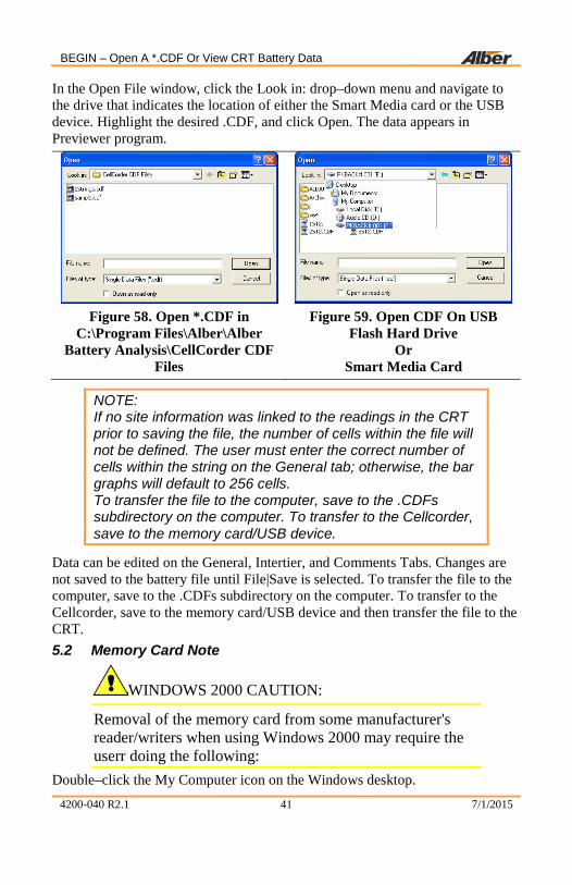
In the Open File window, click the Look in: drop–down menu and navigate to the drive that indicates the location of either the Smart Media card or the USB device. Highlight the desired .CDF, and click Open. The data appears in Previewer program.
Figure 58. Open *.CDF in
C:\Program Files\Alber\Alber Battery Analysis\CellCorder CDF
Files
Figure 59. Open CDF On USB
Flash Hard Drive Or
Smart Media Card
NOTE: If no site information was linked to the readings in the CRT prior to saving the file, the number of cells within the file will not be defined. The user must enter the correct number of cells within the string on the General tab; otherwise, the bar graphs will default to 256 cells. To transfer the file to the computer, save to the .CDFs subdirectory on the computer. To transfer to the Cellcorder, save to the memory card/USB device.
Data can be edited on the General, Intertier, and Comments Tabs. Changes are not saved to the battery file until File|Save is selected. To transfer the file to the computer, save to the .CDFs subdirectory on the computer. To transfer to the Cellcorder, save to the memory card/USB device and then transfer the file to the CRT. 5.2 Memory Card Note
WINDOWS 2000 CAUTION:
Removal of the memory card from some manufacturer's reader/writers when using Windows 2000 may require the userr doing the following:
Double–click the My Computer icon on the Windows desktop.

Generating Reports
4200-040 R2.1 42 7/1/2015
Right click the reader/writer drive icon and select Eject from the pop–up menu. After the message It is now safe to remove the media from the drive appears, the user may remove the memory card. Failure to follow this procedure could result in lost data. Consult the manual for the reader/writer to see if this or other procedures apply. 6 Generating Reports Previewer can print reports with user–specified parameters. A complete report contains cell data tables and graphs. After a report is defined, it can be reviewed in Print Preview before printing. 6.1 Setting Report Options
Open a file, then click the Print button or select File|Print to display the Report Option window.
Figure 60. Report Option
The report creates a tabular list of all data or specific data in the battery file. A bar graph report can be created with or without tabular data. The Report Options window has the following items.
Include Graph, Include Table
Click to include a graph and/or table in the report.
Include Comments If the Comments Tab has notes, select this option to print them in the report.
Select Parameter Selects the voltage, resistance, temperature and SG parameters included in the report.

Exporting Data
4200-040 R2.1 43 7/1/2015
User Defined Report Title and Report Footer
Type a title and footer that will appear on every page of the report.
Footer Options: Date/Time, User Defined, and Page Number
Check these boxes to print on each page the date and time the report was printed, the user defined footer text, and the page number.
After making selections, click OK to display the Print Preview window. To view other report pages, click the toolbar arrows to step to first, previous, next or last page. Use toolbar buttons to increase or decrease page size, print the report, or close the window. 7 Exporting Data Previewer can export graphed data in multiple formats. To open the Export
Option window, click the Export Graph button .
Figure 61. Export Options
To export a file: select the type of export; select the export destination; if available, select the size of the image to export; and click the Export or Print button. Following sections explain this sequence. To export data as an Excel file, click into the radial button next to Microsoft Excel in the Export Option window, select the Excel version, then click OK. Type a file name, choose a location to save the file, then click Save. The Tabular Data Tab is saved in Excel spreadsheet format. To export in Other formats, click into the radial button next to Others in the Export Option window, then OK. The Export File Options window opens.

Exporting Data
4200-040 R2.1 44 7/1/2015
Figure 62. Export File Options
7.1 Export File Type Click a file type button to enable options in the Export Destination and Object Size areas. The following list defines file formats, Metafile, BMP, JPG, Text/Data Only. 7.2 Export Destination Select Clipboard to send a file to the clipboard so it may be copied/pasted into a document. Select File to export as a file. Click Browse to open the File Save As window, type a file name, then click OK. On the Exporting window, click Export. If Text/Data Only is selected, after the user clicks Export, the Text/Data Export window appears.

Exporting Data
4200-040 R2.1 45 7/1/2015
Figure 63. Export Text
Click All Data or Selected Data to export data from all the parameters or only data selected in the Subsets to Export and Points to Export boxes. To choose export data, click Selected Data, then highlight the item in the list. To select multiple items, hold the Shift or Ctrl key while clicking items. Leaving all list box items unselected exports all data. Under Export What, select whether data is exported with or without parameter labels. The following examples are illustrated with one parameter (voltage) and five cells. ♦ Data without labels.
2.183 2.123 2.191 2.200 2.136 ♦ Data and Labels with Y Axis Value selected.
1 2 3 4 5 Voltage 2.183 2.123 2.191 2.200 2.136
♦ Data and labels with Point Number, Y Axis Value selected. 1 2 3 4 5 Voltage 1, 2.183 2, 2.123 3, 2.191 4, 2.200 5, 2.136
Export Style Allows for selection of two styles in which data may be exported: list format and table format.
List Exports the data one record per line. The data fields can either be separated by tabs or commas.

Creating A Data Set
4200-040 R2.1 46 7/1/2015
♦ Tab Format: Voltage 1 2.183 Voltage 2 2.123 Voltage 3 2.191 Voltage 4 2.200 Voltage 5 2.136 ♦ Comma Format:
Voltage,1,2.183 Voltage,2,2.123 Voltage,3,2.191 Voltage,4,2.200 Voltage,5,2.136
Table Exports the data in a grid fashion in either a Subset by Point or Point by Subset style.
♦ Subset by Point: 1 2 3 4 5 Voltage 2.183 2.123 2.191 2.200 2.136 ♦ Point by Subset:
Voltage 1 2.183 2 2.123 3 2.191 4 2.200 5 2.136
Numeric Precision
With Current Precision, data is exported with three decimal places. Maximum Precision exports more than three decimal places when data can support this option. Data results are exported as computed, not as displayed.
Object Size Select the unit of measure and the dimensions for the object, so it will have usable height and width.
Export Destination (continued)
If exporting a Metafile to the printer, click Printer then click Print to open the Print window, select the printer and options, then click OK.

Creating A Data Set
4200-040 R2.1 47 7/1/2015
8 Creating A Data Set This section describes how to create a battery file by typing the data. The user may maintain the file manually or transfer data from the Cellcorder via Smart Media Card or USB device at a later time.
To manually create a battery file, click the Create New button or select File|New. The Select Configuration window appears.
Figure 64. Select Configuration
To copy existing setup data to the new file, click Existing Configuration, select the Location, Battery and String Names, then click OK. To create the file with no setup data, click New Configuration then OK. If an existing configuration was selected, the General and Intertier Tabs display battery information. If a new configuration was selected, begin by editing the General tab. The Tabular Data Tab has all values set to 0 (blank). To edit data on this page, double–click on the grid to open the Cell Data Editor. After values are edited, continue with the Intertier Tab if needed. To save the file, click the Save button or select File|Save. In the Save window, type a file name, then save to the pc’s Cellcorder .CDFs subdirectory. 9 CRT Calibration Backup If the Cellcorder loses calibration data, calibration can be restored instead of sending the unit back to the factory. Factory calibration is backed–up to the memory card/USB device in the file calk.cal.

CRT Calibration Backup
4200-040 R2.1 48 7/1/2015
NOTE: If the user changes the calibration, the user must back up the new edited calk.cal.
If using a memory card, refer to the Memory Card Note section.
♦ Insert a memory card into the CRT–300 card drive or a USB device into the CRT–400 USB drive , then power up the Cellcorder.
♦ To display the Service Menu, at the Main Menu, press Shift+Serv. The password window appears.
♦ Type the password, then press Enter. Default is 1234. ♦ Select Calibration to display the Calibration Menu. ♦ Press Cal–K to display the calibration constants. ♦ To back up calibration data to the memory card/USB device, press Backup. ♦ At Enter File Name, type a name, eight characters maximum for the
calibration file. Albér suggests using the Cellcorder serial number. After typing the file name, press the F2 Save.
♦ The CRT displays Saving Cal–K, then Closing File. When Calibration Constants appear, press Cancel three times to return to the Main Menu.
♦ After the CAL file is saved, copy it from the memory card to the computer under Programs/Alber/Alber Battery Analysis. After copying the file, the user may delete it from the memory card if the user wish.
10 CRT Calibration Backup ♦ Copy the .CAL calibration file from the computer to a memory card/USB
device. ♦ Insert the memory card/USB device into the Cellcorder card drive/USB
port, then power up the Cellcorder. ♦ To display the Service Menu, at the Main Menu, press Shift+Serv. The
password window appears. ♦ Type the password, then press Enter. ♦ Select Calibration to display the Calibration Menu. ♦ Press Cal–K to display the calibration constants. ♦ To restore calibration K–constants to the Cellcorder, press Restore. ♦ Select: Restore from Smart Media (memory card)/USB Device. ♦ Highlight the calibration CAL file using the Arrow keys then press Restore. ♦ When Calibration Constants appear, press Cancel three times to return to
the Main Menu.

Upgrade CRT Firmware
4200-040 R2.1 49 7/1/2015
11 Upgrade CRT Firmware The user can upgrade CRT Cellcorder firmware using the memory card or USB flash hard drive. Albér publishes upgrades to the web at www.alber.com.
NOTE: If using a memory card, refer to the Memory Card Note section.
WARNING: Do not continue until the user has the .UPG upgrade file ready. The user will be clearing the current firmware, which makes the Cellcorder unusable until new firmware is loaded. Download the UPG upgrade file from the Albér Web site or an Albér CD to Program Files/Alber/Alber Battery Analysis. Using Windows Explorer, copy the file to the memory card/USB flash hard drive. With the CRT powered off, insert the memory card/USB device into the Cellcorder. To start in upgrade mode, press Esc+Power On. At the message System is ready to clear Flash memory for new program, to upgrade press Continue or to go to the Main Menu without upgrading, press Cancel. After pressing Continue, at the message System ready to receive upgrade file; select file transfer method, press Smart Media. The message File transfer in progress appears and the frame number counts down. When Upgrade successful; system is running Version nn.nnnnn appears, press Continue to display the Main Menu.
Upgrade CRT Firmware
4200-040 R2.1 50 7/1/2015
Index Add button .................................. 23 ADF
defined BAS .............................. 7 All button .................................... 23 arrow keys ................................... 43 available cells column ................. 22 backup
sample data file ......................... 8 base line ...................................... 36 battery name ................................ 15 BattList.blf .................................. 32 BLF ................................... 7, 32, 37 browse ......................................... 28 button
Add ......................................... 23 All ........................................... 23 Browse .................................... 28 Create New ............................. 53 Current Precision .................... 52 Data ......................................... 50 Edit Values ........................ 13, 18 Existing Configuration ............ 54 Export ..................................... 50 Export Graph........................... 13 Export Graph........................... 48 File Close ................................ 13 File New .................................. 13 File Open .......................... 13, 14 File Save ................................. 13 List Format .............................. 51 Max Precision ......................... 52 New Configuration ................. 54 Other Formats ......................... 49 Point Number .......................... 50 Print Report ....................... 13, 47 radial Excel ............................. 49 Remove ................................... 23 Select Parameters .............. 13, 20
Toolbar ..................................... 7 Transfer Data .......................... 13 Y-axis ..................................... 50
CAL file ........................................ 8 calibration CRT-300 ................... 55 CAUTION .................................. 41 CCF .................................. 8, 24, 25 CD
software .................................... 2 CDF ........................................ 8, 44
to ADF .................................... 13 cell
voltage range .......................... 29 cell data ...................................... 21 cell data editor ............................ 18 celsius ......................................... 38 centigrade ................................... 16 charger frequency ................. 16, 29 clear file list menu item .............. 11 column
order ....................................... 18 sort list view ........................... 17 width ....................................... 18
COM port IR BAS ONLY ......................... 5
comma format ............................. 52 Comments Tab ........................... 24 configuration
file editor .......................... 25, 28 Configuration
Editor ...................................... 25 configuration file
# of strings .............................. 28 battery name ........................... 28 cell voltage range .................... 29 charger freq............................. 29 install date............................... 28 location ................................... 28

Index
4200-040 R2.1 7/1/2015
model number ......................... 28 number of cells ........................ 28 site no. ..................................... 28 string name .............................. 28
configuration wizard ............. 22, 23 current configuration column ...... 22 current precision ......................... 52 Data button .................................. 50 data editor ................................... 18 date
format ...................................... 16 install....................................... 16 read ......................................... 16
date format .................................. 16 demo file ....................................... 8 Docudesk
PDF program............................. 3 dual intercell setting .................... 40 edit configuration file .................. 25 export ........................ 49, 50, 51, 53
graph ................................. 13, 48 fahrenheit .............................. 16, 38 file ................................................. 3
ADF for BAS ............................ 7 BattList.blf .................... 7, 32, 35 BLF ..................................... 7, 32 CAL .......................................... 8 calibration ................................. 8 CCF ..................................... 8, 24 CDF........................................... 8 clear list ................................... 11 close .................................. 10, 13 configuration editor ................. 10 exit .......................................... 10 menu ....................................... 10 new .......................................... 10 open......................................... 10 PDF: .......................................... 3 print ......................................... 10 print setup ............................... 10 program ..................................... 6 reopen ..................................... 10
save ......................................... 13 types ......................................... 7
file types ....................................... 7 firmware upgrade CRT-300........ 56 footer options .............................. 48 general
config file editor ..................... 28 General tab ................................. 14 Ghostscript
program .................................... 4 graph
maximize ................................ 11 return previous ........................ 11 shadows .................................. 11 title .......................................... 11 undo zoom .............................. 11
help ............................................. 12 include
comments check box .............. 48 graph check............................. 47 table check .............................. 47
install BAS .......................................... 2 date ................................... 16, 28 Previewer .................................. 2 software .................................... 2
intercell combined ................................ 40 computed ................................ 40 dual ......................................... 40 quad ........................................ 40 single ...................................... 40 triple ....................................... 40
intertier configuration ................. 22 Intertier tab ................................. 21 IR
BAS ONLY ...................... 1, 4, 5 list view ...................................... 17 location name ............................. 15 maximum precision .................... 52 memory card ........................... 1, 42
caution .................................... 47

Index
4200-040 R2.1 7/1/2015
meta file ...................................... 53 model number ............................. 15
config editor ............................ 28 multiple sites ......................... 25, 38 New button .................................. 53 NOTE ..... 2, 5, 6, 25, 26, 32, 36, 37,
38, 39, 40 number of cells ...................... 15, 28 number of strings ........................ 28 numeric precision ........................ 52 object size ............................. 49, 53 open file
battery data via memory card .. 42 PDF
Docudesk .................................. 3 point by subset ............................ 52 points........................................... 50 print ............................................. 53
report ................................. 10, 13 Print button ................................. 47 program
BAS........................................... 2 CRT Previewer ......................... 2 Docudesk .................................. 4 Ghostscript ................................ 4
quad intercell setting ................... 40 read date ...................................... 16 Remove button ............................ 23 reopen menu item ........................ 10 report ........................................... 47
user defined footer .................. 48 user defined title ...................... 48
report generation ......................... 47 safety ............................................. 1 sample data ................................... 8 select
configuration ............... 10, 53, 54 select parameters ......................... 20
report option ............................ 48 setting
combined intercell ................... 40 computed intercell ................... 41
dual intercell ........................... 40 quad intercell .......................... 40 single intercell ........................ 40 triple intercell ......................... 40
single intercell setting ................. 40 Smart Media . see also memory card
caution .................................... 47 software ........................................ 2
CD ............................................ 2 version .................................... 13
software install ............................. 2 string name ........................... 15, 28 subset by point ............................ 52 subsets ........................................ 50 system
requirements ......................... 1, 2 tab
CFE General ........................... 31 CFE Test Mode ...................... 39 CFE Threshold ....................... 38 Comments ................... 14, 24, 46 General ................... 7, 14, 27, 46 Graph ...................................... 19 Intertier ................. 14, 21, 22, 46 Tabular Data ........................... 16
tab format ................................... 52 table format button ..................... 52 Tabular Data tab ......................... 16 temperature units ........................ 16 test mode/F1 ............................... 43 testing
combined ................................ 40 computed ................................ 40 dual ......................................... 40 quad ........................................ 40 single ...................................... 40 triple ....................................... 40
the Print button ........................... 53 threshold ..................................... 38
config file editor ..................... 39 threshold values .......................... 16 toolbar buttons .............................. 7

Index
4200-040 R2.1 7/1/2015
triple intercell setting .................. 40 type
config editor ............................ 39 config file editor ...................... 39 intercell ................................... 39
UPG file ...................................... 56 USB
device ....................................... 1 www.alber.com .......................... 32