cenet-- capability enabled networking: towards least-privileged networking
TRANSCRIPT

CeNet— CAPABILITY ENABLED NETWORKING:
TOWARDS LEAST-PRIVILEGED
NETWORKING
by
Jithu Joseph
A thesis submitted to the faculty ofThe University of Utah
in partial fulfillment of the requirements for the degree of
Master of Science
in
Computer Science
School of Computing
The University of Utah
December 2015

Copyright © Jithu Joseph 2015
All Rights Reserved

T h e U n i v e r s i t y o f U t a h G r a d u a t e S c h o o l
STATEMENT OF DISSERTATION APPROVAL
The dissertation of Jithu Joseph
has been approved by the following supervisory committee members:
Jacobus Van der Merwe , Chair 07/31/2015
Date Approved
Sneha Kumar Kasera , Member 07/31/2015
Date Approved
Anton Burtsev , Member 07/31/2015
Date Approved
Eric Eide , Member 07/31/2015
Date Approved
and by Ross Whitaker , Chair/Dean of
the Department/College/School of Computing
and by David B. Kieda, Dean of The Graduate School.

ABSTRACT
In today’s IP networks, any host can send packets to any other host irrespective of
whether the recipient is interested in communicating with the sender or not. The downside
of this openness is that every host is vulnerable to an attack by any other host. We ob-
serve that this unrestricted network access (network ambient authority) from compromised
systems is also a main reason for data exfiltration attacks within corporate networks. We
address this issue using the network version of capability based access control.
We bring the idea of capabilities and capability-based access control to the domain of
networking.
CeNet provides policy driven, fine-grained network level access control enforced in the
core of the network (and not at the end-hosts) thereby removing network ambient authority.
Thus CeNet is able to limit the scope of spread of an attack from a compromised host to
other hosts in the network.
We built a capability-enabled SDN network where communication privileges of an
endpoint are limited according to its function in the network. Network capabilities can be
passed between hosts, thereby allowing a delegation-oriented security policy to be realized.
We believe that this base functionality can pave the way for the realization of sophisticated
security policies within an enterprise network.
Further we built a policy manager that is able to realize Role-Based Access Control
(RBAC) policy based network access control using capability operations. We also look at
some of the results of formal analysis of capability propagation models in the context of
networks.

CONTENTS
ABSTRACT . . . . . . . . . . . . . . . . . . . . . . . . . . . . . . . . . . . . . . . . . . . . . . . . . . . . iii
LIST OF FIGURES . . . . . . . . . . . . . . . . . . . . . . . . . . . . . . . . . . . . . . . . . . . . . . vi
ACKNOWLEDGMENTS . . . . . . . . . . . . . . . . . . . . . . . . . . . . . . . . . . . . . . . . . . vii
CHAPTERS
1. INTRODUCTION . . . . . . . . . . . . . . . . . . . . . . . . . . . . . . . . . . . . . . . . . . . . 1
1.1 Thesis Statement . . . . . . . . . . . . . . . . . . . . . . . . . . . . . . . . . . . . . . . . . . . . 11.2 Motivation . . . . . . . . . . . . . . . . . . . . . . . . . . . . . . . . . . . . . . . . . . . . . . . . 11.3 Our System . . . . . . . . . . . . . . . . . . . . . . . . . . . . . . . . . . . . . . . . . . . . . . . . 41.4 Threat Model . . . . . . . . . . . . . . . . . . . . . . . . . . . . . . . . . . . . . . . . . . . . . . . 51.5 Assumptions and Context . . . . . . . . . . . . . . . . . . . . . . . . . . . . . . . . . . . . . 51.6 Thesis Structure . . . . . . . . . . . . . . . . . . . . . . . . . . . . . . . . . . . . . . . . . . . . . 5
2. CAPABILITY PHILOSOPHY . . . . . . . . . . . . . . . . . . . . . . . . . . . . . . . . . . 7
2.1 Capability Model . . . . . . . . . . . . . . . . . . . . . . . . . . . . . . . . . . . . . . . . . . . . 72.2 Example of Capability Systems from Other Domains . . . . . . . . . . . . . . . . . 102.3 Capability Principles Applied to Networks . . . . . . . . . . . . . . . . . . . . . . . . . 112.4 Summary . . . . . . . . . . . . . . . . . . . . . . . . . . . . . . . . . . . . . . . . . . . . . . . . . . 14
3. CAPABILITY NETWORK ARCHITECTURE . . . . . . . . . . . . . . . . . . . . . 15
3.1 Our Approach . . . . . . . . . . . . . . . . . . . . . . . . . . . . . . . . . . . . . . . . . . . . . . 153.2 CeNet Architecture . . . . . . . . . . . . . . . . . . . . . . . . . . . . . . . . . . . . . . . . . . 17
3.2.1 CeNet Capability System . . . . . . . . . . . . . . . . . . . . . . . . . . . . . . . . . 193.2.2 CeNet Host-Side APIs . . . . . . . . . . . . . . . . . . . . . . . . . . . . . . . . . . . 233.2.3 Bootstrapping Capability-Enabled Nodes . . . . . . . . . . . . . . . . . . . . . 233.2.4 Dealing with Legacy Nodes . . . . . . . . . . . . . . . . . . . . . . . . . . . . . . . 30
3.3 Use Case - Preventing Data Exfiltration . . . . . . . . . . . . . . . . . . . . . . . . . . . 343.4 Implementation . . . . . . . . . . . . . . . . . . . . . . . . . . . . . . . . . . . . . . . . . . . . . 37
3.4.1 Capability System . . . . . . . . . . . . . . . . . . . . . . . . . . . . . . . . . . . . . . . 373.4.2 Capability API and Protocol . . . . . . . . . . . . . . . . . . . . . . . . . . . . . . . 383.4.3 Data-path APIs . . . . . . . . . . . . . . . . . . . . . . . . . . . . . . . . . . . . . . . . . 383.4.4 Limitations . . . . . . . . . . . . . . . . . . . . . . . . . . . . . . . . . . . . . . . . . . . . 38
3.5 Performance Evaluation . . . . . . . . . . . . . . . . . . . . . . . . . . . . . . . . . . . . . . . 393.5.1 End-to-end Evaluation . . . . . . . . . . . . . . . . . . . . . . . . . . . . . . . . . . . 393.5.2 Capability System . . . . . . . . . . . . . . . . . . . . . . . . . . . . . . . . . . . . . . . 40
3.6 Summary . . . . . . . . . . . . . . . . . . . . . . . . . . . . . . . . . . . . . . . . . . . . . . . . . . 43

4. HIGH-LEVEL POLICIES . . . . . . . . . . . . . . . . . . . . . . . . . . . . . . . . . . . . . 454.1 Sandbox Master Policy . . . . . . . . . . . . . . . . . . . . . . . . . . . . . . . . . . . . . . . 454.2 Role-Based Access Control (RBAC) . . . . . . . . . . . . . . . . . . . . . . . . . . . . . 464.3 Realizing RBAC Policies Through
Capability Operations . . . . . . . . . . . . . . . . . . . . . . . . . . . . . . . . . . . . . . . . 484.4 Sample Use Case Scenario . . . . . . . . . . . . . . . . . . . . . . . . . . . . . . . . . . . . . 494.5 Rich Sharing . . . . . . . . . . . . . . . . . . . . . . . . . . . . . . . . . . . . . . . . . . . . . . . 504.6 Implementation . . . . . . . . . . . . . . . . . . . . . . . . . . . . . . . . . . . . . . . . . . . . . 53
4.6.1 Evaluation . . . . . . . . . . . . . . . . . . . . . . . . . . . . . . . . . . . . . . . . . . . . 554.7 Summary . . . . . . . . . . . . . . . . . . . . . . . . . . . . . . . . . . . . . . . . . . . . . . . . . . 57
5. FORMAL REASONING . . . . . . . . . . . . . . . . . . . . . . . . . . . . . . . . . . . . . . . 585.1 Formal Models and Security . . . . . . . . . . . . . . . . . . . . . . . . . . . . . . . . . . . 585.2 Take-Grant Model . . . . . . . . . . . . . . . . . . . . . . . . . . . . . . . . . . . . . . . . . . . 595.3 Modeling CeNet System . . . . . . . . . . . . . . . . . . . . . . . . . . . . . . . . . . . . . . 59
5.3.1 What Are the Questions ? . . . . . . . . . . . . . . . . . . . . . . . . . . . . . . . . . 635.3.2 Sharing and Stealing . . . . . . . . . . . . . . . . . . . . . . . . . . . . . . . . . . . . . 65
5.4 Conclusion . . . . . . . . . . . . . . . . . . . . . . . . . . . . . . . . . . . . . . . . . . . . . . . . 68
6. RELATED WORK . . . . . . . . . . . . . . . . . . . . . . . . . . . . . . . . . . . . . . . . . . . 696.1 Capability Architectures . . . . . . . . . . . . . . . . . . . . . . . . . . . . . . . . . . . . . . 69
6.1.1 Take-Grant Model . . . . . . . . . . . . . . . . . . . . . . . . . . . . . . . . . . . . . . . 696.2 Networks and Capabilities . . . . . . . . . . . . . . . . . . . . . . . . . . . . . . . . . . . . . 74
7. CONCLUSION AND FUTURE WORK . . . . . . . . . . . . . . . . . . . . . . . . . . . 767.1 Future Work . . . . . . . . . . . . . . . . . . . . . . . . . . . . . . . . . . . . . . . . . . . . . . . 76
REFERENCES . . . . . . . . . . . . . . . . . . . . . . . . . . . . . . . . . . . . . . . . . . . . . . . . . 78
v

LIST OF FIGURES
3.1 CeNet architecture . . . . . . . . . . . . . . . . . . . . . . . . . . . . . . . . . . . . . . . . . . . . 17
3.2 CeNet capability system . . . . . . . . . . . . . . . . . . . . . . . . . . . . . . . . . . . . . . . . 20
3.3 Bootstrap master . . . . . . . . . . . . . . . . . . . . . . . . . . . . . . . . . . . . . . . . . . . . . 25
3.4 Bootstrap node into capability system . . . . . . . . . . . . . . . . . . . . . . . . . . . . . . 26
3.5 Allow nodes to exchange capabilities . . . . . . . . . . . . . . . . . . . . . . . . . . . . . . 27
3.6 Unidirectional flows . . . . . . . . . . . . . . . . . . . . . . . . . . . . . . . . . . . . . . . . . . . 29
3.7 Bootstrap legacy proxy node and and legacy node . . . . . . . . . . . . . . . . . . . . . 32
3.8 CeNet protocol view . . . . . . . . . . . . . . . . . . . . . . . . . . . . . . . . . . . . . . . . . . . 34
3.9 Data exfiltration . . . . . . . . . . . . . . . . . . . . . . . . . . . . . . . . . . . . . . . . . . . . . . 35
3.10 End-to-end time split . . . . . . . . . . . . . . . . . . . . . . . . . . . . . . . . . . . . . . . . . . 40
3.11 Capability processing time in controller . . . . . . . . . . . . . . . . . . . . . . . . . . . . 41
3.12 Controller bootstrap overhead due to capabilities . . . . . . . . . . . . . . . . . . . . . 42
3.13 Capability access time for different hosts . . . . . . . . . . . . . . . . . . . . . . . . . . . 43
3.14 Capability-enabled and legacy node interaction . . . . . . . . . . . . . . . . . . . . . . . 44
4.1 CeNet Policy manager and RBAC engine . . . . . . . . . . . . . . . . . . . . . . . . . . . 46
4.2 CeNet RBAC roles and polices in a hospital network . . . . . . . . . . . . . . . . . . 47
4.3 CeNet rich sharing scenario . . . . . . . . . . . . . . . . . . . . . . . . . . . . . . . . . . . . . 52
4.4 RBAC overhead . . . . . . . . . . . . . . . . . . . . . . . . . . . . . . . . . . . . . . . . . . . . . . 56
5.1 Protection graph of a simplified hospital network scenario . . . . . . . . . . . . . . 60
5.2 Grant rule applied to G0 [G0 is the Figure 5.1]. “The medical professorgrants (flow to Xray record VM) to student resident.” . . . . . . . . . . . . . . . . . . 62
5.3 Create rule applied to G1 [Figure 5.2]. “The student resident creates/instantiatesa new VM containing his analysis of X-Ray record to which he has flowaccess.” . . . . . . . . . . . . . . . . . . . . . . . . . . . . . . . . . . . . . . . . . . . . . . . . . . . . 62
5.4 Take rule applied to G2 [Figure 5.3]. “The medical professor takes (flow toanalysis) VM from student resident (over whom he has ownership rights).” . . 63
5.5 Protection graph in which the X-Ray record can be stolen . . . . . . . . . . . . . . . 64

ACKNOWLEDGMENTS
I would like to thank my advisor, Prof Jacobus (Kobus) Van der Merwe, for showing so
much interest and faith in this idea. This idea started as a class project in Kobus’ Advanced
Networking Class. His hard work and dedication to research have been an inspiration for
me all along.
I would like to thank Prof Anton Burtsev for the initial idea of exploring capability-
based access control in the context of networks, being part of design and discussion of this
project from its start, and his relentless faith in the capability model.
I would like to thank Prashanth Nayak who was my teammate during the initial phase
of this project.
I would like to thank Prof Eric Eide and Prof Sneha Kasera, who are also part of my
committee for their suggestions and guidance.
I would like to thank Prof Robert Ricci for initially recruiting me to the Flux Group.
Special thanks to all my lab mates: Binh Nguyen, Mohamed Jamshidy, Xing Lin, Ren
Quinn, Hyun-Wook Baek, Richard, and others.
Further I would like to thank Kobus, Anton, and the Flux Research Group for funding
me through my Masters and providing a conductive environment for research.
This material is based on work supported by the National Science Foundation (NSF)
under Grant Numbers 1343713 and 1314945.

CHAPTER 1
INTRODUCTION
1.1 Thesis Statement
Our thesis is: A network version of capability-based access control can realize a more
secure network by allowing only explicitly allowed communications, thereby removing the
ambient authority present in the current network architecture. It further enables delegation
oriented policies to be realized within an enterprise network.
We tested our thesis by building a capability enabled SDN network where the communi-
cation privileges of an endpoint are limited according to its function in the network. In pure
capability mode, hosts interact with each other using the capability APIs and delegation
model. On top of this pure capability mode, we built a policy manager that is able to
translate a Role Based Access Control (RBAC) policy into capability operations, thereby
realizing RBAC access control built into the network core. Rights propagate through a
capability system through well-defined graph transformations, which gives us the ability to
strongly reason about the correctness and security properties of the policy realized by that
system.
1.2 Motivation
One fundamental cause for the increase in cybersecurity threats such as malware is the
inability to secure modern operating systems and applications. Specifically, the traditional
approach that security can be achieved by deploying up-to-date patches on the end host
is no longer valid and cannot resist a well-sponsored, targeted attack. Attackers use a
set of automatic bug-finding tools which have demonstrated the possibility of discovering
zero-day vulnerabilities in every layer of computer system: web browsers, file systems,
network protocol stacks, operating system call interface, hypervisors, firmware of network
and graphic cards, trusted platform modules, and even System Management Mode (SMM

2
1) [1, 2, 3, 4, 5] of the processor. Despite continued advances in host and application
defenses [6, 7, 8, 9], and in software testing and verification [10], the complexity of network
stacks, operating system kernels, language runtimes, and user applications suggests that
endpoint security vulnerabilities will continue to exist.
Once discovered, endpoint vulnerabilities can be exploited to compromise vulnerable
systems through a variety of “distribution” mechanisms: spear phishing, social engineering,
drive-by downloads, email attachments, etc. Once compromised, infected hosts install
additional malware in the form of key loggers, back doors, and command-and-control
software [11]. This malware in turn allows attackers to steal credentials and perform
reconnaissance of the compromised host and its network environment, thus enabling lateral
movement to other hosts within the organization [12]. This exploratory process might
continue for an extended period of time, while “data of interest” is being exfiltrated by
the attackers via the installed back doors [13]. For example, according to a 2013 data
breach report by the Verizon RISK team [11], 62% of breaches remain undiscovered for
several months, while in 36% of cases data ex-filtration occurs within hours of an initial
compromise.
While endpoint vulnerability might be the beachhead for the common attack pattern de-
scribed above [14, 15], we note that the network presents the second fundamental “enabler”
exploited by attackers. First, the malware distribution mechanisms listed above by design
circumvent network firewalls, which still represent the state-of-the-art network periphery
protection, by delivering their malicious payload to an endpoint that is inside a trusted
domain. (Note that this is true whether that be host-based firewalls or firewalls deployed
at the edge of an enterprise or datacenter network.) Once executing on an endpoint inside
the trusted domain, malware essentially has unrestricted network access: Firewall rules
commonly allow connectivity to the outside world, thus allowing malware to create back
doors and command-and-control channels to allow attackers to reach into the protected
domain and export stolen data. Unrestricted access within the protected domain enables
the discovery and exploitation of other vulnerable systems.
Based on the above observations, it is evident that operating system defenses alone
1SMM mode is intended for use only by system firmware, not by applications software or general-purposesystems software.

3
are fundamentally insufficient to address the cybersecurity problem. When host defenses
are compromised (and history suggests it is a question of when, not if ), the compromised
host will have unfettered network access. We note that this unrestricted access represent
a network version of ambient authority in operating systems [16] in which an application
runs with all the authority of the invoking user.
This state of affairs suggests that current network defenses suffer from two fundamental
deficiencies:
• The inability of the network to constrain network interaction based on policies that
define acceptable patterns of communication.
• When communication is constrained, network mechanisms that enforce such con-
straints are coarse grained and divorced from the nuanced needs of network services
and applications.
We argue that to address current cybersecurity concerns, what is called for is a network
architecture that inherently supports three security related primitives:
• Least privileged communication, where the communication capabilities of an end-
point is limited according to its function in the network. In other words the network
core enforces policy driven access control, thereby removing the ambient nature of
network.
• To have these privileges be determined by fine-grained application-driven policies.
• Strong isolation between arbitrary and dynamically created groups of entities, where
the communication within a group is governed by a common set of policies and the
entities have a shared trust domain.
Note that we are not suggesting that network defenses by themselves will be sufficient to
prevent cyber attacks. Indeed, defense in depth principles suggest that current best-practice
host-based protection mechanisms, e.g., those based on lightweight virtual machine con-
tainers [7, 8, 17, 6], be used together with network-based defenses. We are, however,
arguing that more sophisticated network defenses and network defenses that allow for more
meaningful interaction between endpoints and the network are necessary to address the
problem.

4
1.3 Our SystemTowards this vision, this thesis presents our work on Capability Enabled Networking
(CeNet). In CeNet the network-interaction between nodes are explicitly controlled via
capabilities that allow network interactions to be governed by fine grained policies.
A key feature of CeNet is the clean separation of the specification and semantics of
such policies and the enforcement thereof. CeNet assumes an underlying SDN fabric
controlled by the CeNet capability system. The combination of CeNet capability system
and SDN fabric removes network ambient authority by allowing only a policy driven access
in the network. The policies based on which the network-core enforces access control
are however determined by applications running on capability-enabled nodes (within the
limits of their authority) that operate outside the network proper. This separation mirrors
the same partitioning of functionality in capability-enabled operating systems where the
kernel enforces capability restrictions, but the policies of collaboration are determined by
applications [16].
While we envision our work to be more broadly applicable, for this thesis we specif-
ically limit our focus to SDN substrates under single administrative control such as data-
centers and enterprise networks.
We make the following contributions:
• We illustrate how the generic capability access control model applies to a principled
approach to network security.
• We present the design of CeNet, a capability-enabled network architecture that en-
ables strong isolation and least-privileged communication driven by fine-grained
application policies.
• We demonstrate the practicality of our approach by showing how CeNet can seam-
lessly incorporate legacy nodes through capability-aware proxies.
• We present a prototype implementation and evaluation of the CeNet primitives.
• In search of more expressive policies, we explore the utility of combining other
access control models with capability-based access control.

5
• We use the take-grant(tg) model used to formally analyze the propagation of rights
in a capability system, and how formal models can be leveraged to strongly reason
about the correctness of the security properties of the system in a network context.
1.4 Threat ModelCeNet is designed to operate in a modern datacenter or enterprise network environ-
ment. We assume that hosts can be attacked at any time, with and without cooperation of
malicious users. The malicious code will try to use the compromised host for finding and
exploiting remote vulnerabilities in all hosts reachable over the network. CeNet does not
trust anything on the end hosts.
CeNet assumes that the SDN infrastructure—switches and the controller—is trusted.
CeNet does not protect against attacks on the SDN infrastructure. In a virtual datacenter
environment, CeNet extends its trust to include software SDN switches in the end hosts.
CeNet provides policy-driven, fine-grained network-level access control enforced in the
core of the network (and not at the end-hosts), thereby removing network ambient authority.
Thus CeNet limits the spread of an attack from a compromised host to other hosts in the
network.
1.5 Assumptions and ContextCeNet assumes a fixed network where hosts are not mobile. This is a reasonable
assumption in a network where security is an important goal.
The context of this thesis is to specifically address the ambient authority present in
a single-prefix switched local network (consisting of only switches and hosts). Without
CeNet these link-layer switches forward packets based on MAC addresses using their self
learning capability - the downside of which is that it allows a host to send packets to any
other host in the local network.
1.6 Thesis StructureThe following provides a brief outline of the general structure of the rest of this docu-
ment:
In Chapter 2, we describe the idea and philosophy of the capability model. We touch
upon the concepts of ambient authority, principle of least authority (POLA), object capa-

6
bilities, sample systems, etc. Further, we give an outline of our interpretation of how this
model translates to a network scenario.
In Chapter 3, We describe the core architecture of our SDN-based, capability-aware
network. Further, we present the capability model based APIs to be used by the end
hosts to interact with the controller to realize a network devoid of ambient authority, its
bootstrapping, use cases, implementation, and evaluation.
In Chapter 4, we describe how our network is able to enforce access control according
to a high-level policy by translating it into capability operations. We describe an example
scenario, implementation, and evaluation of this.
In Chapter 5, we describe the take-grant (tg) model which is a classic model used
to analyze the propagation of authority in a capability system. Further we present the
major results from the formal analysis of this model. We present an example scenario
on how rights propagate through a network capability system using well-defined graph
transformations of the tg model. We conclude that this gives us the ability to strongly
reason about the correctness and security properties of the policy realized.
The capability model has a rich history of research and in Chapter 6 we summarize the
relevant related works on which this thesis is built.
In Chapter 7 we summarize our contributions and suggest possible extensions to this
work.

CHAPTER 2
CAPABILITY PHILOSOPHY
In this chapter, we describe the principles and philosophy behind the capability model.
We touch upon the concepts of ambient authority, principle of least authority (POLA),
object capabilities, etc. This is followed by a brief overview of a few systems making use of
the aforementioned concepts from other domains like operating systems and programming
languages. Further we give an outline of our interpretation of how this model translates to
a network scenario.
2.1 Capability ModelCapabilities [18] are unforgeable authority-wielding references (tokens). In this thesis,
we will use the word authority to mean the ability of a subject to access a resource (object).
Access to a resource by a subject in a capability system is allowed by virtue of that subject
possessing the capability to that resource. In other words, access requests in a capability
system can only be authorized by capability presentation. The total authority a subject has
in a capability system is conveyed by the capabilities it holds and the transitive closure
of what the possession of those capabilities permits. Subjects have no ambient authority.
Capability systems restrict the authority of a subject by simply limiting the capabilities
it holds. Isolation between two untrusted subjects may be achieved granting them non-
overlapping capabilities.
Some salient features of capability model are described below:
• No designation without authority. Capabilities are a means of realizing authorization-
based access control, which contrasts with the typical identity-based access control,
which uses Access Control Lists (ACLs) to specify permissions. The ACL model
presumes some namespace, such as the space of filenames, that subjects use to
designate resources. This namespace must be separate from the representation of
authority [19] in an ACL system. Miller claims that this separation (designation

8
problem) [19] is arguably one of the deepest problems in computer security. Capa-
bilities combine into one entity the name of the object they are referring to and the
permissions required to access that object.
A deputy is an entity that must manage authority coming from various sources. A
confused deputy can be tricked into wielding its authority inappropriately. Aforemen-
tioned atomicity (grouping the name of the referred object and the permissions re-
quired to access it) provides a strong tool for avoiding confused deputy problem [20]
as it leaves no room for ambiguity about what authority is being exercised during a
request to access a resource. Thus the Capability model simplifies the implementa-
tion of trusted systems by unifying addressing and protection mechanisms [21].
• Principle of least privilege [22]. This principle states that every entity should operate
using the minimal set of privileges necessary to complete its task. Delegation is a
key idea in the capability model that facilitates this principle. A subject can easily
delegate part of its authority to another subject by passing on a capability.
• Only connectivity begets connectivity [23]. The only ways to get a capability in
a capability system are by introduction, endowment (construction) or parenthood
(creation).
A capability system as considered in this work can represent the computer system as a
graph of subjects connected with edges that represent rights, or capabilities. The labels on
the edges indicate the type of the capability (explained in the following chapter).
The object-capability model [24] replaces the traditional subject-object dichotomy with
the notion of objects from programming languages that function as both subjects that
initiate access and objects which are targets of action [25]. In such systems capabilities
are references to objects. In such a system capabilities allow objects to interact with each
other, e.g., invoke functions, send messages, and exchange rights.
In a capability system, the only way to access a resource is to invoke a capability, or a
reference to a capability, that enables access to a particular object. In our context invoking
a capability means invoking operations via our APIs (explained in the following chapter)
with the capability (designating the resource) as an argument.

9
Multiple formulations of the capability model exist [18, 26, 27, 28, 29, 30]. At a high
level, the capability model can be captured with three core operations: create, grant, and
revoke. These operations provide rules for mutating the protection graph, i.e., creating new
objects, adding new edges to the graph, and removing existing edges. The create operation
allows any object (with appropriate capabilities) to create a new object. The new object
is isolated by default. It can be accessed by its creator via a capability returned by the
create operation. The grant operation enables transfer of rights from one object to another.
The grant operation takes an existing capability as an argument and passes it to the grantee
object. Naturally, the grant operation requires that the granter had a capability to access the
grantee. Finally, the revoke operation removes the rights from the object.
Capabilities provide a foundation for both discretionary and mandatory access control.
Capabilities travel only along the edges of the capability graph. By default, all subjects are
created with no authority and receive all rights as capabilities from other subjects.
Capability access control [18, 26, 24] provides a foundation for constructing secure sys-
tems in the face of persistent exploitable vulnerabilities and untrusted components [31, 16].
In the face of exploitable and untrusted components, practical security can be achieved by
partitioning a large, untrusted system into small pieces that have minimal rights. Capabili-
ties are designed as a mechanism that
1. helps minimizing authority of individual applications in a complex environment with
a large number of dynamic principals; and
2. provides a formal control model that defines interactions between untrusted compo-
nents and outcomes of untrusted computations.
The rules of the capability system limit the exchange of capabilities (flow of rights)
across objects. The capability models are shown to be decidable: by looking at the initial
distribution of capabilities it is possible to decide the upper limit of authority for individual
subjects in face of all possible transformations to the system and future exchanges of
rights [26]. By controlling the initial distribution of capabilities, it is possible to ensure
confinement [30]. Confinement in the context of capability systems can be stated as the
ability of the system to limit the propagation of authority. This property can be used to cre-
ate runtime compartments satisfying certain security properties as given in the EROS [30]
work.

10
The capability model contrasts with Mandatory access control (MAC) in the following
way [16]:
• Interest of whom - MAC caters to the interest of an administrator, whereas capabilities
cater to the interest of the user or application.
• Policy source - MAC rules are specified in global policy files whereas policy is
embedded in application code for capabilities (capabilities are quite good in allowing
code to express policy)
• Granularity - MAC suffers from coarse granularity (due to broad sweeping policies).
Consequently, it is very hard to isolate rights, whereas capabilities sometimes help in
this scenario.
As observed by Miller in one of his talks, early system security research was focused
only on the needs of individual corporations which had central control and which saw
delegation and propagation of delegation as a problem. Today, decentralized cooperation
between organizations and individuals is becoming increasingly prevalent, and delegation
may be better suited to achieving this. But we should do delegation in ways of least
authority. Literature about capabilities argues that the excessive authority implicitly granted
by traditional access control mechanisms (which does not support least authority delega-
tion) is the reason behind the massive prevalence of security vulnerabilities [32]. The
object-capability paradigm, with its pervasive and extensible support for the principle of
least authority, enables mutually suspicious interests to cooperate more intimately while
being less vulnerable to each other [32].
2.2 Example of Capability Systems from Other DomainsCapability model has been used in multiple domains like operating systems and pro-
gramming language :
• Operating systems: Many systems claim strong security benefits, just by removing
ambient authority. In most cases this just means disallowing global name-spaces for
user processes and allowing them to operate only on explicitly granted file descriptors
(capabilities). Some examples are Polaris [33], Capsicum [34] and Plash [35].

11
Another system based on capability model, SEL4 [36] has formal proofs that it can
correctly enforces high level security properties like integrity and authority confine-
ment.
• Programming languages: Various object-capability languages like E, Joe-E, Emily,
and W7 are used to create web mashups that use contents from untrusted third parties,
while allowing rich interactions among the third party contents and also between
embedding page and third party contents. The aforementioned object-capability
languages are restricted (specialized) subsets of larger programming languages, in-
tended to provide capability safety by eliminating language constructs (e.g., static
variables) that could leak authority.
• Networking: Generic capability access control model has not been applied to net-
work access control. This thesis is the first work in this direction.
2.3 Capability Principles Applied to NetworksThe key principle enabling security in capability systems is the ability to construct
small, isolated computations that operate on a minimal number of isolated resources. By
minimizing the authority of individual computations, a capability system provides a guar-
antee that even if part of the computation is compromised, the possible impact is minimal
and limited to the set of objects reachable through capabilities. (Note that the citations in
the emphasized portion in this section are not capability systems, but systems with certain
desirable security properties. The intention is to point out that a capability based network
can realize those properties.)
• Isolation by default. Capability systems ensure that objects are isolated by default.
Objects are created with no implicit rights to access any resource in the system.
In a capability controlled network all communication is initially blocked [37]. Nodes
receive individual capabilities to open network connections. This model encourages
careful distribution of rights and significantly reduces the attack surface compared
to traditionally “open by default” systems and networks.
• Fine-grained computations and resources. To ensure that authority of individual
computations is minimal, capability systems rely on fine-grained isolation of com-

12
putations and resources. The ability to create fine-grained computations is based on
support from underlying hardware and software platforms.
In a networked system, isolation can be provided at the granularity of physical or
virtual machines. Isolation at the level of individual physical machines, even though
fairly coarse grained, is a big improvement over the traditional state of the art in
network security—granularity of an entire network. Virtualization is a de facto part
of the system stack in datacenter environments and is also increasingly being used for
fine-grained isolation in end systems [7, 8, 17, 6]. As such it provides a lightweight,
fine-grained, and practical mechanism for running computations and hosting data
objects in isolation. Combined with fine-grained network isolation, virtualization
becomes a foundation for least-privilege datacenter and enterprise environments.
• Fine-grained delegation of rights. The capability model is designed to extend
fine-grained isolated environments with the flexible, dynamic, and fine-grained man-
agement of rights. In a capability system, delegation is a transfer of rights from one
object to another. Being able to selectively grant subsets of their rights, applications
naturally minimize the authority of individual computations. To isolate itself from
potentially untrusted code, a capability-enabled application follows the following
pattern: The application creates an isolated execution environment. This environ-
ment receives a minimal set of rights required to complete the computation. The
result of the computation is obtained through a narrow, well-defined result protocol.
Even if part of the computation is compromised, the effect of the compromise is
confined by the capability system and underlying isolation mechanisms.
In a capability-enabled network, fine-grained delegation of rights guarantees that
nodes receive minimal rights to access network resources, e.g., constrained to spe-
cific computational resources, or hosts servicing data objects, thus preventing access
to other parts of the network and obstructing multistage attacks [38].
• Local policy decisions. In contrast to traditional mandatory access control models,
capabilities do not rely on the notion of a centralized access control policy. Instead,
capabilities enforce a hierarchy of access control restrictions. High-level policies
define security guarantees and information flow across coarse-grained parts of the

13
system. At the same time, applications have complete freedom to enforce their local
access control decisions on the subset of resources they reach through capabilities.
Applications are encouraged to combine the principle of fine-grained compartmental-
ization with their internal logic to minimize the authority of individual computations.
The hierarchical nature of capability access control ensures that in a capability-
controlled network, it is possible to securely split resources across multiple tenants,
but at the same time guarantee that each tenant has freedom to enforce local secu-
rity policies inside its isolated compartment. Natural integration of access control
decisions and application logic allows a maximal realization of the principle of least
authority. The access control policy remains encoded inside the application logic,
not at the level of system interface [39, 40]. Networked applications are free to make
local policy decisions on a per-request basis — a degree of dynamism and granu-
larity that is simply not available in traditional access control frameworks. Further,
the ability to make local policy decisions solves many access control management
problems inherent to the nonhierarchical access control models [39, 41].
• Capability design patterns. The basic capability model enables confinement by
completely isolating parts of the protection graph [30]. Complete isolation is in-
sufficient in a practical system. Parts of the system need to communicate. The
true power of capabilities is revealed when the base capability model is extended
with a small set of trusted objects that serve as security-enforcing abstractions [24].
Similar to design patterns in object-oriented languages, trusted capability objects
implement object capability patterns [24]—composable access control abstractions.
Object capability patterns are designed to enable security guarantees for mutually
mistrusting components [24, 42]. A number of object capability patterns exists to
implement a variety of access control patterns, e.g., one-way information flow (diode
pattern [24]), revocable rights (caretaker pattern [24]), applying a specific policy to
all capabilities reachable from the initial capability (membrane pattern [24]), and
responsibility tracking (Horton protocol [42]).
In a capability-controlled network, a set of well-designed access control patterns that
have well-understood behavior and guarantees enable scaling of secure protocols in

14
the face of complex, mistrusting parties.
2.4 SummaryIn this chapter, we looked at the principles and philosophy behind capability model.
Further we gave an overview of our interpretation of how this model would translate to a
network scenario.

CHAPTER 3
CAPABILITY NETWORK ARCHITECTURE
In this chapter, we describe the core architecture of our SDN-based, capability-aware
network. We present the capability model-based APIs to be used by end hosts to interact
with the controller to realize a network devoid of ambient authority, its bootstrapping, use
cases, implementation, and evaluation.
3.1 Our ApproachIn CeNet we use the fundamental properties of capability systems, discussed in the
previous chapter, as a foundation to realize strong network security. We think of policy-
driven access control being built into the network so that only permitted interactions are
allowed by the network core.
This contrasts with traditional network access control mechanisms in the following
manner:
• Firewalls
– Usually present only at the network periphery. Per host firewalls can provide
fine grained access control within the local network, but they have certain
limitations listed below.
– High-level policy is interpreted by network admin and manually translated into
firewall specifics. This limitation is applicable to both peripheral and per host
firewalls.
– For per-host firewalls — it is difficult to make changes to an implemented policy
as ACLs are distributed at various places.
– For per-host firewalls — it is difficult to reason about the type of access al-
lowed by the network, since the policy is implemented in such an ad hoc and
distributed fashion.

16
– For per-host firewalls — if the OS on a host is compromised, it no longer
has control over the attacker probing the internal network via arbitrary pack-
ets, whereas in our approach even if an end-host OS is totally compromised,
networks still enforces access control.
• VLAN
– Creates smaller ambient networks. The inherent ambient authority increases
the potential attack surface for a host. It also increases the damage when things
are compromised at a host.
We start by considering hosts in a network as fundamental objects and go on to identify
other objects which signify ownership, reachability, and delegation to hosts in the network.
We develop the model by identifying a set of operations (based on the capability model)
that allow applications running on hosts to collaborate and utilize the network in a secure
manner.
Our host side control path APIs provide the means for hosts to receive rights over
other network objects. One particular type of right (called a flow capability) gives a
host the permission to send data packets to another specific host. As a result of the
control interactions by which a sender received a flow capability to a specific receiver, the
network is programmed to steer data packets containing flow capabilities to the appropriate
destination host.
Further, we have mechanisms to bootstrap hosts with initial capabilities. We have a
bootstrap policy manager which helps to easily specify a coarse-grained network policy to
start with.
We recognize the following benefits of the capability model in a network scenario:
• Allowing the network owner to specify a coarse grained policy at the top level.
• Allowing a level of dynamism, decentralization, and evolution of policies within the
aforementioned protected domains via the concept of delegation. This can be done
via our host side APIs, which interact with the capability system.
• The ability to reason about the protection state of the system.

17
3.2 CeNet Architecture
CeNet is an object capability [24] system that extends traditional networks with fine-
grained access control, dynamic management of rights, and secure collaboration (Fig-
ure 3.1). CeNet treats the hosts of a traditional network as a collection of objects in the
capability system. Network communication, host management (in this work this means
ownership), and exchange of rights are mediated and controlled by the rules of the CeNet
capability system. CeNet builds on two core principles: strong isolation and controlled
communication. To ensure isolation, CeNet operates in the context of an environment
where all hosts are connected to a software defined network (SDN). CeNet uses the under-
lying SDN substrate to prevent all communication until it is explicitly allowed. As shown in
Figure 3.1, the CeNet capability system is implemented as an SDN controller application.
In CeNet all network communication is controlled according to the rules of the capability
SDN
Nodes
RendezvousPoints
Flows
ObjectsCapability Spaces
Capability Enabled Node
Legacy Node
Capabilities
Cap
abili
ty P
roto
col
Capability Protocol
Capability API
Capability-enabledApplications
SDN Controller
Capability System
Capability System
Capability Enabled Node
Legacy NodeProxy
Capability Protocol
Capability APIProtocolHandler
CapabilityProxy
Proxies
Figure 3.1. CeNet architecture

18
model. Network nodes can open network connections and communicate with each other if,
and only if, they possess a capability for such a connection.
CeNet provides support for both pure capability-enabled and unmodified legacy nodes.
This pragmatic approach eases adoption by being backwards compatible, while at the same
time allowing new functionality to be realized. Capability-enabled nodes run a capability
protocol that allows capability-enabled applications to interact with the capability system,
e.g., exchange rights, establish network connections and specify access control policies.
Legacy nodes do not have any awareness of the capability system, but are seamlessly
incorporated in CeNet through a mechanism of legacy node proxies. Legacy node proxies
are special nodes designed to provide backward compatibility with legacy protocols in a
capability network. Proxies intercept protocol interactions from legacy nodes and translate
them into capability invocations. After the network flows are established with the help
of proxies, legacy nodes directly use the network to interact with other legacy nodes or
capability-enabled nodes.
CeNet provides a clean separation of the policy and mechanism for access control in
computer networks. CeNet implements the mechanism—a clean, flexible layer of access
control. The combination of CeNet capability system and SDN fabric removes network
ambient authority by allowing only a policy driven access among hosts in the network. The
policies based on which the network-core enforces access control are, however, determined
by applications running on capability-enabled nodes (within the limits of authority granted
to them) that operate outside the network proper.
The CeNet separation of policy and enforcement and the delegation of rights inherently
enabled by capability systems provide for a powerful security primitive that cleanly maps
onto existing communication models, while also enabling the realization of novel commu-
nication models.
For example, the degenerate case of a single (or replicated) capability-enabled node that
runs a network management application mimics the prevalent “logically centralized” SDN
control application approach [43, 44]. While such a system would not fully utilize CeNet
features, it would still benefit from realizing higher-level policies in a capability system
with clean delegation and revocation abstractions.
A more sophisticated use case might involve a multitenant datacenter environment

19
where a subset of nodes and complete control of the policies associated with that subset
might be delegated to each tenant. For this use case, the applications are essentially
capability-enabled nodes that are allowed to manipulate the capability system (according
to the rights delegated to them) and as a side effect create flows in the SDN substrate
according to application-specific policies.
For both scenarios described above, capability manipulation is essentially limited to
control-plane operations. However, as we describe below, the CeNet API also provides
data send and receive functionality. This allows for complete end-to-end capability-enabled
interaction between applications. For example, in such a scenario, all hosts in the system
may be capability enabled, so that both control and data plane interaction between the
nodes will require the use of capabilities.
In Section 3.2.1 below, we first consider the functionality of CeNet assuming a “pure
capability” environment where all nodes are capability-enabled. In addition to simplifying
the exposition, this represents a realistic scenario for networks with high security require-
ments. Later we describe how CeNet deals with legacy nodes.
Note that the terms application/host/node and endpoint are used interchangeably be-
cause in a security critical scenario, it is likely that an application would be running all
by itself within a physical host, virtual machine, lightweight container, or would have a
lightweight network stack linked directly into its address space [45, 46]. Our host-side APIs
are geared more toward these single-function security use cases. In this initial version of our
work, our APIs do not satisfactorily address the security requirements for a general-purpose
network stack that must demultiplex the packets to various application processes.
3.2.1 CeNet Capability System
CeNet exposes the resources of a computer network through a capability interface.
Capabilities mediate all network operations, e.g., the ability to open and accept new con-
nections, the exchange of rights and the management of network hosts.
3.2.1.1 Capabilities
The core of CeNet is the capability system (Figure 3.2). Network hosts access resources
of the network by invoking capabilities. Capabilities both name specific objects and provide
authority to perform operations on them. Objects represent resources of the network.

20
Rendezvous
Flows Proxies
CapabilityObject
Nodes
Node B
recv ( , ...)
Capability System
SDN Controller
Node A
send( , ...)
CSpace
SDN Network
64-bit CapabilityName
Figure 3.2. CeNet capability system
Possession of a capability allows a node to perform a specific operation on the object.
However, hosts do not have any intrinsic authority beyond that accessible via capabilities.
Hosts refer to capabilities by their local names—64-bit capability identifiers that have
no special meaning outside of the host. For each host the CeNet capability system maintains
a capability space (or a CSpace), a datastructure that resolves local capability identifiers
into capability references that contain specific rights to a specific object. The difference
between capability identifier and capability reference is merely an implementation detail
and the translations are handled automatically by the system. In the context of our system
if we merely mention the term capability (without being specific of whether it is a capability
identifier or reference), it usually means a local capability identifier in the context of a host,
which is translated (by the capability system in the central SDN controller) to an object
pointer (reference) referring to a unique object (Section 3.2.1.2 below provides a detailed
description of object types supported by CeNet) in our system.
Hosts invoke capabilities via the CeNet capability application programming interface
(API). The API maps onto a simple capability protocol that conveys API invocations to
the CeNet controller. Each capability protocol message contains a capability identifier
which designates a receiving object, an operation to perform on the object, and one or

21
more arguments.
A host is identified by its location on the network. A location is the switch identifier
and the port-number, through which the host attaches to the network. The unforgeable
property of capability identifiers in our system is based on the fact that capability creation
or transfer happens (via CeNet APIs) only with the knowledge of the capability system
in the controller. Later, when a host presents a capability, for exercising its authority, the
RPC messages are tagged with the originating switch and port identifier by the Openflow
switches. The capability system can easily validate whether this token was indeed granted
to this particular host. Since switch firmware is part of our Trusted Computing Base (TCB),
it is impossible for a malicious host to exercise a nongranted capability token.
3.2.1.2 Objects
Objects encapsulate the logic of host management, connection establishment, and capa-
bility management operations. Objects provide the only interface for a CeNet application
to interact with the environment of the network. For example, the invocation of a capability
on a flow object allows a node to establish a unidirectional flow to the host pointed to by
the flow object. State and code of the objects is part of the CeNet capability system. CeNet
defines four object types:
• Node: Each physical or logical node (VM) in the system is represented by a node
object. Node objects implement a management interface to the physical and logical
hosts of the CeNet system. A capability to a node allows its owner to reclaim the node
and reset it to a clean state by power cycling the node, controlling its boot protocol,
and reseting its capability space. By controlling the distribution of node capabilities,
CeNet enables flexible partitioning of the network resources. Control over any node
can be delegated to any node within the system.
• Rendezvous point: A rendezvous point is a communication primitive that enables
nodes to exchange capabilities via send and receive operations. A rendezvous point
maintains a queue of messages from the sender. When the receiver invokes a receive,
the capabilities are transferred to the receiver.
• Flow: A flow object enables establishing a unidirectional flow for data-path com-
munication between nodes. Only the receiving end of the flow is fixed when the

22
flow object is created. Like any capability, capability to a flow object can be passed
around and invoked multiple times. Any node that possesses a capability to a flow
object can open a network flow to the receiving end. CeNet relies on support from
the underlying SDN to establish flows.
• Proxy: Proxy objects allow proxy nodes to proxy all the control plane traffic (DHCP,
DNS and ARP) of a legacy node (to the proxy node) and translate them to capability
operations, thereby mediating its exchange of rights. Thus CeNet uses proxy objects
to allow legacy nodes to interact with the capability system in a transparent manner.
The proxy object allows a node which holds a capability to the proxy to invoke
capability exchange operations on behalf of the legacy node associated with the
proxy object. When the proxy object capability is passed into a capability exchange
operation, the operation is performed on the CSpace of the legacy node that is pointed
to by the proxy object.
3.2.1.3 Operations
Capability operations define the rules for modifying the state of the protection graph of a
capability system. CeNet implements a version of the take-grant capability model [26, 47].
The CeNet capability model allows the following operations:
• Create. The create operation creates a new object of a requested type. Create returns
the capability pointing to the new object to its caller. Create operations can be used to
create new RP and flow object types. Node and Proxy objects are not usually created
(as semantically it doesn’t make sense) by endhosts. They are created and their
capabilities are received by admin and proxy hosts, respectively, during bootstrap.
• Mint. The Mint operation creates a new capability that points to an existing object.
Mint is typically done before a grant (delegation) as it allows for the revocation of
a minted capability by the minter at a later point of time (by passing the original
capability to the revoke operation). This operation is object type agnostic.
• Send and receive. Nodes exchange capabilities by passing them into the send and
receive operations. Send and receive operate on rendezvous objects. Any node which
23
has a capability to a specific rendezvous point can send and receive messages to the
RP.
• Send and receive data. Send and receive data operations allow nodes to use the
CeNet API for data plane communication.
• Revoke. The revoke operation allows the invoking host to delete the object pointed
to by the capability. This renders useless all the minted capabilities which it might
have delegated to others. It is object type agnostic.
• Reset. The reset operation cleans the capability space of a node and resets it with a
single rendezvous point available to the node through the well-known CAP0 capa-
bility identifier. The invoker should have a node capability to the target node for this
operation to succeed.
3.2.2 CeNet Host-Side APIs
Capability operations are exposed to hosts via an API. The primary function of the
capability API is to enable hosts to interact with the controller to manipulate the protection
state of the system. The API can also be leveraged for datagram-based messaging functions.
3.2.3 Bootstrapping Capability-Enabled Nodes
In this section we first explain how nodes are bootstrapped into the capability system.
We then consider how such a bootstrapped node can use the CeNet communication primi-
tives to establish communication between nodes.
In any network administrative domain, enterprise, datacenter or cloud, there are certain
high-level network management policies that govern the roles and functionalities of nodes
in the system and effectively form the context within which any detailed policies are
applied. For example, in a datacenter or enterprise environment, specific nodes would
be designated to run “infrastructure services” like DHCP and DNS. Likewise, in the cloud
infrastructure, specific nodes will be designated to run the “cloud control” software stack
while other nodes will be designated as compute nodes.
Our goal with CeNet is to provide a generic framework that can accommodate and
enhance the functionality of any of these scenarios (and indeed enable alternative scenar-
ios). Without loss of generality, in our exposition below we assume that some higher level

24
management function has designated a master node that has full control over a number
of other nodes in the system. Because a master node can in turn dynamically delegate
“submaster” capabilities to any of the nodes it controls, this setup applies to all of the
scenarios mentioned above. For example, the master node might be the sole master node in
a datacenter or enterprise environment, or it might be a master node for a subset of nodes
belonging to a specific customer or department in a datacenter or cloud infrastructure.
3.2.3.1 Bootstrapping Master Node
Figure 3.3 depicts the scenario in which Master0, a node which has control over three
physical nodes, creates a new isolated network partition. Master0 chooses one of the three
nodes to become the master inside the partition (Master1). The master bootstrap protocol
allows Master0 to pass control over the partition to Master1. Figure 3.3 (a) shows the initial
state of the capability system. Master0 possesses capabilities to the three nodes. To start
the master boot protocol, Master0 invokes the following operations:
capRP0 = create (TYPE_RP)
reset (capM1, capRP0)
capM1_M1 = mint (capM1)
send (capRP0, capM1_M1)
capN1_M1 = mint (capN1)
send (capRP0, capN1_M1)
capN2_M1 = mint (capN2)
send (capRP0, capN2_M1)
Master0 creates a new rendezvous point RP0. It then invokes a reset operation on
Master1. The reset operation performs two things. First, it cleans the capability space
of the node. Second, it inserts the rendezvous object RP0 in the empty CSpace of the
reset node (Master1). After reset, the node has no capabilities besides a capability to the
rendezvous object. Similar to the UNIX environment, the rendezvous object serves as the
“standard input” for Master1. It is used to exchange capabilities while performing the boot
protocol. The reset operation arranges that the rendezvous object is available to the node
through a capability with a well-known name, 0.
Master0 uses the mint operation to create copies of capabilities referring to three nodes
and the send operation to send these capabilities to the rendezvous point RP0. The master
mints capabilities, so it can revoke them later without losing its own control over the nodes,

25
N1M1 N2
Master 1
RP0
/ / Mast er 1 - st ar t up pr ocedur e/ / get al l capabi l i t i eswhi l e( 1) { r ecv( CAP0, &cap, &t ype) / / per f or m pr ocessi ng based / / on capabi l i t y t ype}
N1M1 N2
RP0
N1M1 N2
Master 1 Node1 Node2
Node1 Node2
(b)
Node1 Node2
(c)
capN2
capN1
capM1
Master 0
0
CapN2_M1
CapN1_M1
CapM1_M1
Master 0
CapRP0
CapM1
CapN1
CapN2
Master 0
CapRP0
CapM1
CapN1
CapN2
Master 1
0
CapN2_M1
CapN1_M1
CapM1_M1
(a)
CSpace
Capability
RendezvousPoint
NodeObject
Figure 3.3. Bootstrap master

26
which it has through capabilities capM1, capN1, and capN2.
Given this initial state, Figures 3.3 (b) and (c) depict the bootstrapping actions when
the master node starts up. The master invokes the receive operation on its “standard
input” capability “0” to receive the node capabilities waiting in the rendezvous queue.
Figure 3.3 (c) shows how this results in the enqueued capabilities being imported into the
capability space of Master1. Note that the manipulation of the capability space shown in
these figures occurs in the data structures of the capability system (associated with the SDN
controller), as a result of invocations via the CeNet API (shown in Figure 3.2).
3.2.3.2 Bootstrapping Other Nodes
The above bootstrap protocol is followed to bootstrap any capability-enabled node
into the system. For example, to bootstrap Node1, the Master1 executes the following
commands:
capM1_N1RP0 = create (TYPE_RP)
reset (capN1, capM1_N1RP0)
capN1_N1 = mint (capN1)
send (capM1_N1RP0, capN1_N1)
The master node creates a new rendezvous object capM1 N1RP0. The master then
invokes the reset() operation on the node referred by the capN1 capability, and passing the
capM1 N1RP0 rendezvous capability as an argument, thus establishing Node1’s RP0. The
master mints the capability to the node and sends it to the rendezvous object. Figure 3.4
shows that Node1 follows the same startup procedure (i.e., performing a receive operation
on the capability “0”). After receive, Node1 is fully bootstrapped into the capability system.
It has a capability to itself, which allows it to create new objects, e.g., rendezvous points and
N1M N2
Master1Node1
Node2
RP0(Master1's RP0)0
N1RP0(Node1's RP0)
CapM1_N1RP0
0
CapRP0
Master0
CapM1_M1
CapN1_M1
CapN2_M1
Figure 3.4. Bootstrap node into capability system

27
flows, and to receive more capabilities from the master through its standard input capability
zero.
3.2.3.3 Allowing Nodes to Exchange Capabilities
Once nodes are bootstrapped into the capability system, the master node (or any node
with appropriate capabilities) can create a rendezvous point to allow nodes to exchange
capabilities directly. Figure 3.5 presents an example of three nodes, in which a new
communication channel is set up between the two nodes Node1 and Node2. Master1
can exchange capabilities with Node1 and Node2 through the existing rendezvous objects
N1RP0 and N2RP0 (from the bootstrap of those nodes). Master1 executes the following
commands to create a new rendezvous point and share it with both nodes:
capN1N2RP = create (TYPE_RP)
capN1_RP_N2 = mint (capN1N2RP)
send (capM1_N1RP0, capN1_RP_N2)
capN2_RP_N1 = mint (capN1N2RP)
send (capM1_N2RP0, capN2_RP_N1)
The master creates a new rendezvous object. The master then mints two new capabili-
ties from the rendezvous point capability and sends these capabilities to Node1 and Node2
via the rendezvous points they share with the master (N1RP0 and N2RP0). Both nodes
receive capabilities to the new rendezvous object with the receive operation. The receive
operation imports the appropriate capabilities into the capability space of the receiver. The
end state, with the new rendezvous point shared between Node1 and Node2 is depicted in
Figure 3.5. (To simplify the figure we show only the relevant CSpaces and objects.)
Master1
Node2
N2RP0capM1_N2RP00
capM1_N1RP0
N1RP0
Node1
0Client
ServerN1N2RP
capN1_RP_N2
capN2_RP_N1
Figure 3.5. Allow nodes to exchange capabilities

28
3.2.3.4 Communication Primitives
With the ability to exchange capabilities in place, nodes in a CeNet system can create
communication-related objects (flow objects) and exchange the associated capabilities to
enable communication. Again, the semantics associated with such communication will
be application-specific, according to the delegation of capabilities amongst participating
applications, while the enforcement of the policies will lie with the capability-driven SDN
infrastructure. For example, to realize the common “logically centralized” policy manager
approach, a centralized master node can create flow objects on behalf of nodes under its
control and pass the capabilities associated with these objects to the nodes in question
(via shared rendezvous points). Nodes receiving these capabilities will thus be enabled to
communicate according to the policies enacted by the master node.
CeNet’s ability to delegate capabilities, however, also enables the realization of fine-
grained, distributed policies. For example, Figure 3.6 depicts the scenario where a client
and a server are explicitly enabled to exchange capabilities (as illustrated in Figure 3.5)
and use this ability to create flow objects and exchange the associated capabilities to enable
client/server communication.
With reference to Figure 3.6, Node2, acting as a server and wanting to enable com-
munication with a client (Node1), will perform the following invocations via the CeNet
API:
capInUFlow = create (capN2, TYPE_UFLOW, flow_spec)
send (capN2_RP_N1, capInUFlow)
...
recv (capN2_RP_N1, &capOutUFlow)
Figure 3.6 (a) shows the result of these invocations. The server creates a new flow
object and shares it with the client through a rendezvous point they share. The flow is of
type, TY PE UFLOW , indicating that it is a unidirectional flow towards the server and with
a optional flow specification. flow spec can be used to demux packets at the receiving host
to multiple applications if required (somewhat like port numbers). Note that at this point,
the flow object only exists in the capability system; no flow has actually been realized in
the SDN substrate. CeNet can also proactively push flow specification to the substrate if

29
Node2
Client Server
N1N2RP
capN1_RP_N2capN2_RP_N1
capInUFlow
capInUFlow
Client Server
N1N2RP
capN1_RP_N2capN2_RP_N1
capInUFlowcapOutUFlow
capOutUFlowcapInUFlow
flow specificationpushed to network
Client Server
N1N2RP
capN1_RP_N2capN2_RP_N1
capInUFlowcapOutUFlow
capOutUFlowcapInUFlow
Node2Node1
Node1
(a)
Node2Node1
(b)
(c)
Figure 3.6. Unidirectional flows
the flow-type is specified as TY PE UFLOW PUSH.
The client, Node1, will receive the unidirectional flow object. The client then creates a
flow pointing in the other direction as follows:
recv (capN1_RP_N2, &capOutUFlow, &type)
capInUFlow = create (capN1, TYPE_UFLOW, flow_spec)
send (capN1_RP_N2, capInUFlow)
senddata (capOutUFlow, data)
The client API invocations essentially mirror that of the server in terms of creating
a unidirectional flow object towards the client and sharing it with the server via the ren-
dezvous point. The client then starts sending on the flow capability it received from the
server. As shown in Figure 3.6 (b), receiving data on the flow capability will result in the
flow specification being pushed into the SDN substrate so that subsequent interaction will
not involve the controller. In a similar fashion, once the server has performed a receive

30
to import a flow capability generated by the client, capOutUFlow, the server can use
senddata() with the capability to send data to the client. Again, this flow of data will
serve as a trigger to push the flow specification into the SDN substrate as depicted in
Figure 3.6 (c).
A key property of the take-grant capability system is the transitive, reflexive, and
symmetric closure over all Grant connections (discussed in more detail in Chapter 5).
This closure provides an authority bound which is invariant over system execution. Our
bootstrap protocol is based on this. In other words, any amount of capability transfer from
the initial bootstrapped state cannot introduce a new connection between two objects that
were not already connected by some path in the closure.
3.2.4 Dealing with Legacy Nodes
We envision that complete autonomous environments, e.g., high security datacenters,
could run the CeNet system and protocols. However, to ease adoption, backwards com-
patibility with legacy nodes is an important requirement. As described earlier, CeNet deals
with legacy nodes by delegating control of such nodes to proxy nodes capable of interacting
with both the legacy nodes (via legacy protocol handlers) and with the capability system
through the CeNet API (and protocol).
Two scenarios are of interest. The first is a domain consisting of only legacy nodes.
With appropriate higher-level policies driving the CeNet capability system and with dele-
gation to different master nodes, this scenario still benefits from CeNet’s least-privileged
communication and strong isolation primitives.
In the second scenario, legacy nodes are integrated into a CeNet environment and
allowed to seamlessly communicate with capability-enabled nodes. For example, in such a
mixed-node deployment, a capability-enabled server could grant or deny access to clients
based on fine-grained application-level policies and have those policies be enforced by the
SDN infrastructure.
The mechanisms involved with both scenarios are essentially the same. Without loss of
generality we consider the mixed deployment scenario below in more detail.

31
3.2.4.1 Bootstrapping Proxy and Legacy Node
Our approach to integrating legacy nodes into CeNet builds on two insights. First, most
protocols used by legacy nodes are of a request/response nature. These protocols readily
map onto the send and receive functions exposed by the CeNet API to share capabilities
and import them into a node’s capability space. Below we consider one possible mapping
making use of DHCP, DNS, and ARP protocols.
Second, since the capability identifiers used by hosts for invocations across the CeNet
API have local significance only, the proxy can maintain a mapping between capability
identifiers and legacy “protocol identifiers.” For example, the IP and MAC layer addresses
used by legacy protocols in effect become “proxy capability identifiers.”
Figure 3.7 illustrates this scenario. Node2 is a capability-enabled server. Node1 is a
legacy client. The Master node sets up a system in which nodes Node1 and Node2 are
allowed to communicate. The master designates a Proxy node to act on behalf of Node1.
Proxy node is responsible for performing capability operations on behalf of a legacy node,
so as to seamlessly integrate the legacy node into the capability-enabled network. The
master then creates a proxy object. Note that this instance of create() invocation takes a
capability to the legacy node as the first argument. The create operation associates the
proxy object with the legacy node. The master shares the proxy capability with the proxy
node:
// On Master
capP = create (capN1, TYPE_PROXY) //CapP points to ProxyN1 object in figure
capP_N1 = mint (capP) //CapP, CapN1 in master’s CSPace are not shown
send (capM_RP_P, capP_N1)
// On Proxy
recv (capP_RP_M, &capProxy_N1, &type)
When the proxy node receives the proxy capability, the CeNet capability system con-
figures the SDN substrate in such a way that all control plane traffic, e.g., DHCP, DNS and
ARP, from the legacy node is routed to the proxy node.
Figure 3.7 (a) depicts the result of Master resetting the legacy node Node1 for boot-
strapping it into the capability-enabled network. The rendezvous point N1RP becomes the
standard input for Node1. Another rendezvous point is created for communication between
Node1 and Node2 (N1N2RP). The master has sent associated capabilities to appropriate

32
rendezvous points. Note that from Master perspective these operations are exactly the same
as the actions it took to bootstrap a capability enabled node as described in Section 3.2.3.
The legacy node bootstrap continues when Node1 initializes its network interface, e.g.,
after reboot. At this point the legacy node issues a DHCP request. DHCP traffic from the
legacy node is routed to the proxy. The proxy node receives and parses the DHCP request
from the legacy node. The proxy realizes that the legacy node is ready to join the network.
The proxy performs the node part of the bootstrap protocol on behalf of the legacy node.
The receive operation below imports capabilities from the rendezvous point N1RP into the
capability space of the legacy node Node1. (The result of these operations is shown in
Figure 3.7 (b)):
// On Proxy
while (recv(capProxy_N1, 0, &cap, &type)) {
//capability specific processing
}
Although the receive invocation is invoked by the proxy node, the receive operation is
performed on the CSpace of the legacy node, i.e., the node pointed by the capProxy N1
Proxy
Node1(legacy)N1RP
capM_RP_N1
capProxy_N1
ProxyN10
Node2
Master
N2RP
N1N2RP
capN1_RP_N2
capN2_RP_N1
capM_RP_N2
capN2_RP_M
N1RP
capM_RP_N1
capProxy_N1
ProxyN1
0
N2RP
N1N2RP
capN1_RP_N2
capN2_RP_N1
capM_RP_N2
capN2_RP_M
Master
Node2
Node1Proxy
(a)
capP_RP_M
PRP
capM_RP_P
capP_RP_M
PRP
capM_RP_P
(b)
(legacy)
Figure 3.7. Bootstrap legacy proxy node and and legacy node

33
capability. The capability which points to the RP “0” is also taken from the CSpace of
the legacy node. On successful invocation of the functions above, the proxy protocol
handler performs regular DHCP functions based on the received request. It returns a
DHCP response and maintains the mapping between the DHCP parameters and capability
identifiers it received on behalf of the legacy node. (For example the proxy can maintain
a mapping between the IP it issued in response to Node1’s DHCP request, the proxy
capability id corresponding to Node1 and list of Node1 local capability identifiers like
capN1 RP N2, received as a result of the recv in the previous snippet.)
In the code sequence above, the receive operation is used with an additional argument—
a capability to the proxy object.
Once the legacy node and the proxy node are bootstrapped in this manner, the same
protocol is followed for setting up data flows. (The exchange of rights for setting up a
CeNet flow is shown in Figure 3.6.) The proxy intercepts regular protocol exchanges
from the legacy node and translates them into capability operations. Specifically, the
capability-enabled server (Node2) will invoke the exact same capability operations to cre-
ate a unidirectional flow object towards itself (Figure 3.6 and Section 3.2.3.4).
To realize the flow in the other direction, i.e., from the legacy client (Node1), the legacy
node issues a DNS request to resolve the server hostname to an IP address. This request
is directed to the proxy node. Based on the information that the request came from Node1
the proxy node uses the proxy capability associated with Node1 (capProxy N1) to invoke
the receive operation:
// On Proxy
recv (capProxy_N1, capN1_RP_N2, &capOutFlow, &type)
On success, the proxy again proceeds with regular protocol processing, i.e., construct-
ing a DNS response message and responding to the client.
On initiating communication with the server, the client issues an ARP request to resolve
the MAC address of the server. Again this message is intercepted and parsed by the proxy.
The proxy then proceeds to create a flow from the client to the server:
// On Proxy
capInFlow = create(capProxy_N1, TYPE_UFLOW, spec)
send(capProxy_N1, capN1_RP_N2, capInFlow)

34
At this point the capability space is in the same state as at the equivalent point in
Figure 3.6 and IP based flow table entries can be pushed proactively to route the packets
between the two hosts (on the intermediate switches connecting them), thus allowing the
two hosts to communicate.
3.2.4.2 Hybrid Nodes
In Sections 3.2.1 and 3.2.3 we assumed that capability-enabled nodes would use the
messaging functionality of the CeNet API for any node-to-node communication (Figure
3.8 (a)). This functionality is not practical for communication between capability-enabled
nodes and legacy nodes. Instead, we make a reasonable assumption that for this type of
interaction, the capability-enabled node would make use of a regular (legacy) network stack
for “data path” interaction with the legacy node, but use the CeNet API for the “control
plane” interaction with the capability system (Figure 3.8 (b)).
3.3 Use Case - Preventing Data ExfiltrationTo illustrate the utility of our approach, we consider how the CeNet capability system
can prevent data exfiltration in an enterprise network setting. The requirement here is to
create enterprise network functionality, where different parties need to get their work done,
but at the same time limit the damage and loss of data in the event of a security compromise
at any of the hosts.
Capability SystemCapability
API
ProtocolHandler
ProxyMapping
CapabilityAPI
SocketAPI
Appl
SocketAPI
Client Proxy Server
App
SDN
CapabilityAPI
Server
App
CapabilityAPI
Client
App
Capability System
SDN
Capability Protocol
Data Path
Legacy Protocols(non data path)
(a)
(b)
Figure 3.8. CeNet protocol view

35
In our example scenario shown in Figure 3.9, the network needs to allow the following
interactions:
• a host with sensitive data needs to be accessed by a data scientist
• a group of three employees working on a project needs to collaborate
• the company needs to serve web pages showing the current inventory status, which
is available on the database hosted on a different machine.
The fine-grained network access control (provided by capabilities) can alleviate the
spread of a malware (e.g., exploiting a zero-day vulnerability, and all hosts are unpatched).
This in turn can reduce the scope of data exfiltration in such a corporate network.
During the bootstrap, the master entrusts each host with only the capabilities it requires
to perform its task.
Here the webserver serves webpages to the external world, so during bootstrap, the
master gives it only the capabilities (flow capabilities) required to interact with the database
server and vice versa. In the event of some security loophole in one of the scripts executed
by the webserver, or some zero-day vulnerability in the web server code or host networking
Figure 3.9. Data exfiltration

36
stack code, the attacker (even with root privileges of the webserver) can only reach the
database server, thereby leaving other parts of the network safe from attacks. In this
scenario, the attacker might be able to exfiltrate the webdata, but the network would not
provide him a chance to attack and exfiltrate the sensitive data.
Similarly the master establishes a rendezvous point, which allows the data scientist
and the system hosting the sensitive data to exchange flows that would enable them to
communicate.
In the case of three employees needing to collaborate, the master need not get into
the specifics of their collaboration. The system allows the nature of collaboration of these
three host, to be decided by one of them (submaster). To achieve this, master delegates the
ownership of those three nodes to one among them (say the host designated for the project
manager). Now the project manager can decide the actual nature of collaboration among
the three. By carefully granting just the three node capabilities to the project manager, the
master can accomplish two goals: flexible collaboration and isolation of the three from the
rest of the network. The protection state of the whole system could continue to evolve based
on how the project manager host allows the remaining two to collaborate among themselves
and with him. But no sequence of operations (capability-graph mutations) would enable
these hosts to get a capability to other hosts in the network.
Why capabilities? Functionally this achieves security guarantees similar to running
firewalls on every individual host, but the existing method of placing ad hoc firewall rules
on endhosts leaves many opportunities for misconfiguration (if users are allowed to change
the endhost firewall rules) and is difficult to reason about the overall security state of the
network, as there is no explicit way of tracking rule changes. This level of fine grained se-
curity can be realized more easily in traditional SDN systems (like Ethane [43]). However,
the policies are dictated by a single policy file without any scope of delegation, dynamism
or evolution.
The capability model permits a level of evolvability from the bootstrapped protection
policy of the system. End hosts can determine the policies based on delegated capabilities,
thereby allowing a level of decentralization. However, the nature of evolution of protection
state is using well defined graph transformations and consequently it is possible to reason
about the protection state at any point in time or the possible upper bound of authority

37
propagation.
To summarize, the following are the key advantages of CeNet system:
• policy-driven access control by the network core
• delegation of authority with the ability to revoke
• dynamic changes
• reason about the access allowed
3.4 ImplementationTo verify the feasibility of our approach, we realized a prototype implementation of the
CeNet architecture. The main components are the capability system, the capability API,
and a bootstrap protocol.
3.4.1 Capability System
The CeNet capability system is implemented as an application in the POX SDN con-
troller. POX is an extendable SDN controller implemented in Python. CeNet relies on POX
functionality for all network management operations, e.g., maintaining a centralized view
of the network, creating network flows, etc. The CeNet capability protocol, objects, and
operations directly extend the functionality of the POX controller application.
Capabilities are implemented as Python objects within the controller process. A ren-
dezvous point is a producer-consumer buffer that allows nodes to exchange capabilities.
The buffer preserves the order in which messages were received. A flow object has the
source and destination host information (source information is populated when the flow
object is received by the senders). Based on these the path between the given hosts can be
calculated based on the network topology. At the time when a flow is pushed into the SDN
substrate, the CeNet system computes the route as a list of switch and input-output port
combinations of intermediate switches. It also has methods to proactively push flows (both
forward and reverse) in all the switches. In our current implementation we are giving the
network topology and paths (between host pairs) as an input to the system, but it should
be possible to hook into the network topology discovery module of POX to automatically
compute the path.

38
The capability class maintains a reference to one of the capability objects and some
logic for generating unique capability identifiers. Capabilities are associated with specific
hosts. CeNet relies on a pair of switch identifier and port number to uniquely identify a
host for each capability invocation. The CeNet system keeps track of capabilities for each
node in a capability space, or CSpace, data structure. We use a simplified implementation
of the CSpace—a list. This works well for the small number of capabilities, but does not
scale. In other systems, capabilities are kept in radix trees with guards [48, 10]. Capability
spaces for all nodes are kept in a Python dictionary—a key-value data structure indexed by
a pair (switch id , port number) that uniquely identifies each host.
While we have implemented the logic associated with the reset operation as far as
the capability space is concerned, we have not implemented the external mechanisms that
might be associated with this operation to physically reset nodes.
3.4.2 Capability API and Protocol
CeNet implements the capability API that can be directly utilized by capability-aware
applications. The API provides capability applications with remote access to interact
with the capability system. Remote invocation of the capability operations is built on the
capability protocol. Our realization of this protocol is implemented as a simple request /
response protocol on top of UDP. The payload of each capability protocol message contains
the capability operation to be performed, as well as the capability identifier needed for
that operation. Each message also contains any additional parameters associated with the
specific operation.
3.4.3 Data-path APIs
Our current implementation of data-path APIs Send / receive data overloads the VLAN
field to carry the flow capability (token) and we route based on this capability. We use
rawsockets to construct the packets.
3.4.4 Limitations
The limitations of our implementation include the following:
1. The data APIs currently support only UDP messaging. Connection oriented seman-
tics need to be implemented over this.

39
2. Realizing traditional ambient networks (where every host needs access to every other
host) using flow capabilities may create pressure on SDN flow table entries. In our
model, the same destination would be identified by different flow capabilities in the
context of different hosts. While this is a desirable security property, it limits scope
of flow aggregation (to the same destination).
3.5 Performance EvaluationWe did a basic performance evaluation of our primitives. Our evaluation focuses on
an end-to-end evaluation of CeNet, the scalability of the capability system itself, and the
functionality of the legacy node proxy. We evaluated our prototype implementation in a
Mininet network emulation environment controlled by a POX-based SDN controller with
the CeNet capability system and executing on a 2.1 GHz Intel Xeon system running Ubuntu
Linux.
3.5.1 End-to-end Evaluation
Once the appropriate capability operations have been performed to realize flows, CeNet
uses the SDN network directly and there is no further overhead due to capabilities. Our
evaluation therefore focuses on an end-to-end measurement of the overhead introduced by
the CeNet capability system.
Typically, the capability-related overhead would come in two scenarios: (i) the addi-
tional overhead to bootstrap new nodes into the capability system or handing over addi-
tional capabilities to existing nodes and (ii) the additional overhead introduced in setting
up flows between two hosts interested in communicating. The first operation happens when
a master at a particular level delegate authority of a subset of nodes to a master at a lower
level in the delegation tree. As such this operation is not in the communication critical path.
The second operation introduces some overhead as a flow object needs to be created and
the associated capability passed to the other end of the communication.
We evaluated this overhead by instrumenting our implementation to determine the
breakdown of time within end-to-end API invocations for CeNet capability operations.
These results were obtained with the capability system preloaded with 840 nodes and with
the CSpace of each node populated with 1,000 capabilities.
Our results are shown in Figure 3.10. The bars show the average total time for each

40
0
2
4
6
8
10
12
14
recv create mint send
Time (m
s)
Opera-ons
Controller end to host
Capability Processing end to Controller end
Capability processing
Controller start to Capability Processing start
Host to Controller start
Figure 3.10. End-to-end time split
CeNet operation. Our first observation is that the operations introduce fairly modest over-
head, somewhere between 11 and 13 ms, depending on the operation. Each bar is divided
to show the relative contributions of different components in an end-to-end invocation.
The bottom component (“Host to Controller start”) and top component (“Controller end
to host”) represent the overhead of the capability protocol to get the request from the
invoking host to the capability system. The request/response nature of our capability
protocol is evident, and since this is a remote invocation, these two measures make the
largest contribution to the end-to-end delay.
The three components in the middle of each bar represent the SDN controller receive
processing (“Controller start to Capability Processing start”), the actual capability pro-
cessing (“Capability processing”), and the SDN controller send processing (“Capability
Processing end to Controller end”). Interestingly, the actual capability processing makes
the smallest contribution, with controller-related processing dominating.
3.5.2 Capability System
To get a sense of its scalability, we evaluated our capability system in isolation. Fig-
ure 3.11 shows the capability-related overhead of the receive operation and how this over-
head varies according to the number of capabilities in the CSpace. The shape of the graph
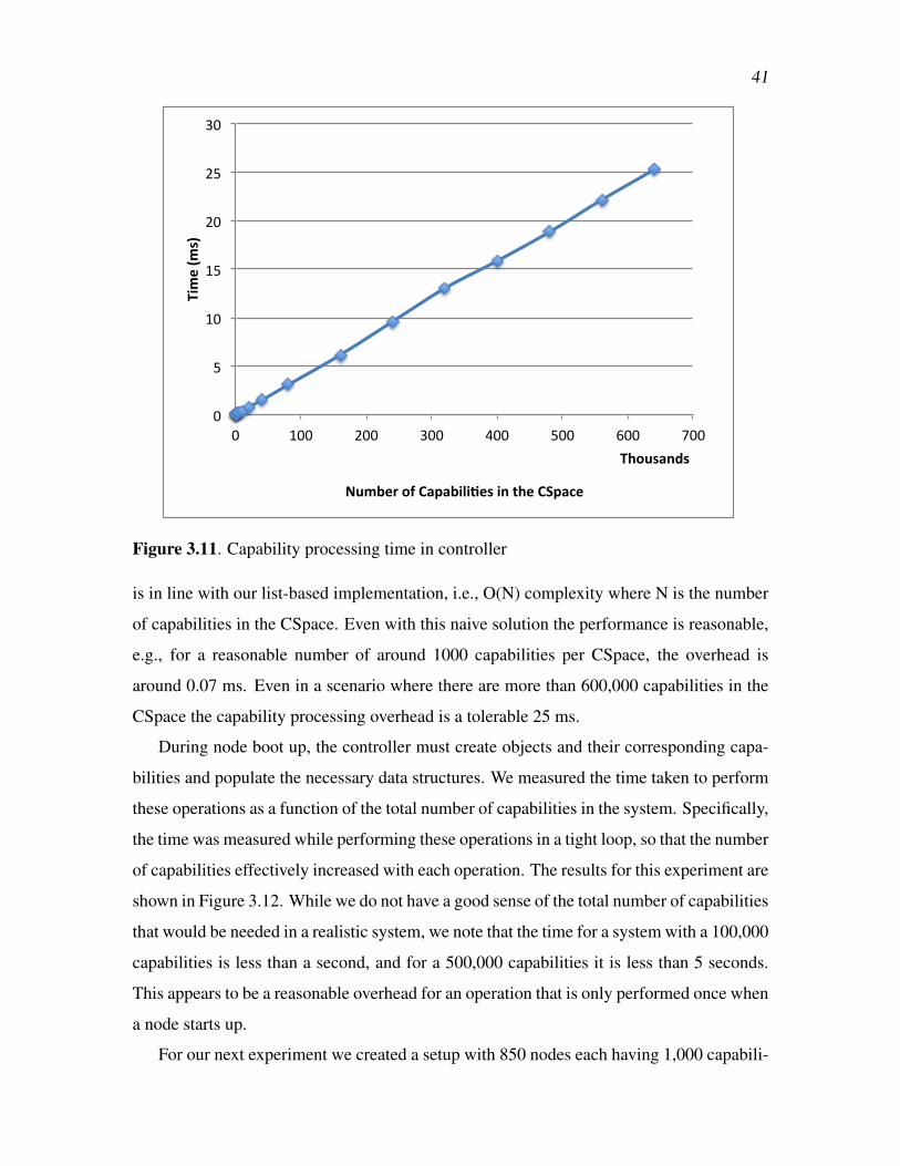
41
0
5
10
15
20
25
30
0 100 200 300 400 500 600 700
Time (m
s)
Number of Capabili3es in the CSpace
Thousands
Figure 3.11. Capability processing time in controller
is in line with our list-based implementation, i.e., O(N) complexity where N is the number
of capabilities in the CSpace. Even with this naive solution the performance is reasonable,
e.g., for a reasonable number of around 1000 capabilities per CSpace, the overhead is
around 0.07 ms. Even in a scenario where there are more than 600,000 capabilities in the
CSpace the capability processing overhead is a tolerable 25 ms.
During node boot up, the controller must create objects and their corresponding capa-
bilities and populate the necessary data structures. We measured the time taken to perform
these operations as a function of the total number of capabilities in the system. Specifically,
the time was measured while performing these operations in a tight loop, so that the number
of capabilities effectively increased with each operation. The results for this experiment are
shown in Figure 3.12. While we do not have a good sense of the total number of capabilities
that would be needed in a realistic system, we note that the time for a system with a 100,000
capabilities is less than a second, and for a 500,000 capabilities it is less than 5 seconds.
This appears to be a reasonable overhead for an operation that is only performed once when
a node starts up.
For our next experiment we created a setup with 850 nodes each having 1,000 capabili-

42
0
1000
2000
3000
4000
5000
6000
7000
0 100 200 300 400 500 600 700
Time (m
s)
Number of capabili3es
Thousands
Figure 3.12. Controller bootstrap overhead due to capabilities
ties in their CSpace. Figure 3.13 shows the capability-processing overhead in the controller
for a randomly chosen set of 250 hosts from this setup. The graph shows that, since the
first-level indexing is hash based, the capability-related overhead for an operation is more
or less the same irrespective of the host. The graph also shows that the capability processing
is quite stable: the average time for all 850 nodes was 0.07 ms with a standard deviation of
0.01.
Legacy proxy node. We performed a functional evaluation of our proxy node imple-
mentation. Specifically, within our Mininet environment we created the setup depicted in
Figure 3.8 (b). In this experiment the capability-enabled server node invoked appropriate
capability operations to create a flow in the SDN substrate towards itself. We then manually
performed a DHCP request from the legacy node to trigger the client-side operation. On
receiving a successful DHCP response from the proxy node, we manually performed a
ping <hostname> on the legacy node. This first triggered a DNS request to resolve the
hostname and then a subsequent ARP request to resolve the server’s MAC address. We
captured the network interaction for this experiment via tcpdump in the Mininet setup.

43
0
0.01
0.02
0.03
0.04
0.05
0.06
0.07
0.08
0.09
0 50 100 150 200 250
Time (m
s)
Host id
Figure 3.13. Capability access time for different hosts
Figure 3.14 shows an annotated time series of the interactions between the components in
this setup.
3.6 SummaryIn this chapter we talked about a mechanism for providing practical security, fine-
grained access control, and least privilege in traditionally open networks. Based on prin-
ciples of capability access control, we develop a powerful access control model which fits
the needs of a modern data center or enterprise network. Capabilities enable fine-grained
isolation and delegation of rights in a hierarchical, dynamic, multitenant environment, with
a large number of mistrusting principals. While ensuring global security properties, CeNet
allows individual hosts to make application-specific decisions. This natural integration
of the application logic and access control enables construction of true least privileged
environments.

44
Figure 3.14. Capability-enabled and legacy node interaction

CHAPTER 4
HIGH-LEVEL POLICIES
In this chapter, we describe how our network is able to enforce access control according
to a high-level policy by translating it into capability operations. We describe an example
scenario, implementation, and evaluation of this.
We refer to the component that does the aforementioned translation as a policy man-
ager. It sits above the capability system in the SDN controller as shown in Figure 4.1
and translates a high-level policy into a set of capabilities and hands them over to the
relevant CSpaces using capability operations. The CSpaces now mirror that policy and our
capability-based SDN controller enforces it over the network. This essentially bootstraps
the network with an initial coarse grained policy.
The primary advantage of the network enforcing policy-based access control (versus an
ambient network) is that this approach of least privileged networking reduces the potential
attack surface for a host (in a network). It also reduces damage (to other hosts in the
network) when the integrity of a host (in a network) is compromised.
We have experimented with the following two policies: sandbox master policy and
Role-Based Access Control (RBAC).
4.1 Sandbox Master PolicyThis policy mirrors what we called Master0 in the previous chapter. This allows spec-
ifying the master which has full control over a number of other nodes in the system. The
policy manager grants the relevant capabilities (node capabilities to hosts in the sandbox)
to the master.
The sandbox master, during its bootstrap, receives the capabilities granted as per the
network bootstrap policy and now using the capability APIs it can decide on the nature of
fine-grained collaboration among the other nodes in the sandbox. Thus the system allows
policy evolution.

46
Policy Manager
RBAC Engine
SDN
SDN Controller
Capability System
policy.xml
1. Roles and Role Hierarchies2. Host to Role assignment3. Capability to role assignments (Policies)
Policy : Allow role = Cardio
Role = Cardio
Object HostsSubject Hosts
Role = Nurse
2
Figure 4.1. CeNet Policy manager and RBAC engine
Except for some implementation details later on, we do not discuss this further in this
chapter as this corresponds to Master0 bootstrapping Master1 from the previous chapter.
4.2 Role-Based Access Control (RBAC)Role-Based Access Control (RBAC) [49] is used for protection of resources in struc-
tured organizations like hospitals, universities and companies [50]. RBAC regulates access
to resources based on the roles of individual users within an enterprise.
In addition to reducing the attack surface, introducing RBAC in our system simplifies
the task of bootstrapping a large network with the correct access control policy. We observe
that while the bootstrapping procedure as mentioned in the last chapter works well for
a small network (providing fine-grained control), it might be overwhelming to specify
it in the same fine-grained fashion for a large network. With RBAC, we do not assign
capabilities directly to hosts (users); instead, we use RBAC to manage what capabilities a
host gets. RBAC introduces the role concept; capabilities are assigned to roles, and roles
are assigned to hosts.

47
RBAC Parameters and Policies: Consider a simplified hospital network scenario
as given in Figure 4.2. We have hosts belonging to doctors (with varied specializations
like cardiologist, physician etc.), nurses, and file servers (hosting medical records, payroll
records etc). To simplify the policy specification, we choose to classify the hosts in the
network as subject hosts and object hosts, where object hosts are data repositories like file
servers and subject hosts are client devices from which those data may be accessed.
The following RBAC functionalities are supported by our system:
• Creating/specifying roles in the system. Some examples of roles from the aforemen-
tioned scenario are cardiologist, nurse, etc.
• Host to role assignment. Again in the context of our example scenario, this means,
host N1 belongs to a physician and host n4 belongs to a nurse.
• Permission (capability to a host) to role assignment. Reachability (flow) to a partic-
ular host would naturally be the fundamental permission (capability) in our system.
It is possible to augment this with other types of capabilities like admin (node capa-
bility), delegation (rendezvous point capability) rights, etc.
Staff
NurseDoctor
CardiologistPhysician
Record
host N1 host N2
host N4
Medical Rec Payroll Rec
vm host N3 host N5
Policy : Allow role = Cardio
Policy : Allow role = Staff
a. Subject Role hierarchy and host associations
b. Object Role hierarchy , host association and policies
admin
Figure 4.2. CeNet RBAC roles and polices in a hospital network

48
To be more precise the assignment of permissions to roles can be represented as a
tuple:
(sub j role× capability type(FL)×ob ject role) (4.1)
Note that for convenience our system allows to specify an obj host instead of an
obj role as the third parameter in the above equation. An example of this from our
sample scenario is (doctor× f low capability×host N3) which allows connectivity
between hosts that are assigned doctor roles and the object host N3. We synony-
mously call this association a policy. (Again, to be more correct, the whole policy of
the network would be comprised of many such individual policy items.)
• Role hierarchies - RBAC has the concept of a role hierarchy, which is a natural
means for structuring roles to reflect the lines of authority and responsibility in
an organization. Figure 4.2 shows the hierarchy of roles in our hospital network
scenario. We show general roles towards the top of the tree and specific roles toward
the bottom.
There is a natural concept of delegation (along the lines of organizational authority
and responsibility) embedded in this role hierarchy tree. This allows us to obtain the
desired policy granularity by specifying the policy in terms of roles at any level of
the tree. Say for example, with reference to Figure 4.2, if a policy specifies allow <
sta f f > access to < hostN5 >, this is enough to allow the cardiologist role to access
N5, by virtue of being a more specialized version of the doctor role, which is a
specialized version of the staff role. This further simplifies policy specification.
4.3 Realizing RBAC Policies ThroughCapability Operations
Assume the aforementioned four parameters — roles, host to role assignments, permis-
sions to role assignments, and role hierarchies — are provided for an enterprise network.
It is then possible to evaluate which hosts are entitled to receive which capabilities. This
allows us to populate the CSpaces of our subject hosts, thereby enabling us to easily
bootstrap the capability systems for our network.
Our policy manager in a sense precalculates the closure over all allowed connectiv-
ity between hosts based on the role-hierarchy tree and a given policy. Then it invokes

49
the CeNet API to instantiate the lower-level polices in the appropriate CSpaces (thereby
freeing us of the burden of invoking the capability APIs manually to realize a policy).
This translation (closure calculation) is straightforward and more details are present in the
implementation section.
4.4 Sample Use Case Scenario
Our system allows us to specify network access control in the form of a high-level
RBAC policy. The policy manager consults an input file to gather roles, host to role
assignments, role hierarchies, and policies, which are the basic parameters of an RBAC
system.
Coming back to our hospital network scenario in Figure 4.2, one of the policy items
specified is (role cardiologist × f low capability× role med rec). During bootstrap the
RBAC policy manager, based on the aforementioned RBAC parameters in the policy file,
would identify the hosts between which the network should allow connectivity based on
this policy. Based on this, it would invoke the CeNet API to instantiate the lower-level
polices in the appropriate CSpaces.
For this simple case and policy, we have only one subject host with the role cardiologist
(host N2) and only one object host with the role medical record (VM host N3). As per the
policy, the network would allow this interaction. The cardiologist host (host N2) can use
the flow capability (endowed by the policy manager as a result of composing this policy)
and data-path APIs to interact with the medical record host (VM host N3). Simultaneously,
the switches would be programmed to recognize this flow capability and would route them
to the relevant output port, which ultimately leads to the destination.
This system is sufficiently higher-level than the pure capability system, as the RBAC
policy specified can be at a high level (based on coarse/fine roles), and the policy manager
realizes the corresponding network access control using CeNet APIs. Mostly the end-hosts
need to be only aware of the capability-aware data-path APIs. The creation and delegation
of capabilities mirroring the high level policies are handled by the policy manager.
Discussion. It is possible to achieve RBAC and similar levels of delegation at a higher
level (e.g., at the level of files) using capability-based authentication services (at the appli-
cation layer) running over a traditional ambient network. But if the integrity of a host OS is

50
compromised, these higher level protection schemes fail to be of much use in constraining
the attacker from targeting other vulnerable hosts in the network.
The difference in our approach is that we are implementing security at a lower layer.
This gives us the advantage that even when a host OS is compromised, policy-driven access
control enforced by the network provides a layer of protection.
For example, in the event that a nurse’s host is compromised, the attacker can only
reach (attack) hosts that the nurse had reachability to. In a traditional network, assuming
all hosts had some zero-day vulnerability in their network stack, the attacker would be able
to target every host once it gains a foothold on the nurse’s host.
4.5 Rich SharingUntil now we have considered flow capabilities, which deal with subject to object host
connectivity, and this is enough to realize a basic RBAC system. The policies are specified
with respect to object hosts (object roles). Once bootstrapped, the policies are static in this
basic RBAC system.
CeNet allows for a more dynamic approach by factoring in other types of capabilities
like node capability, RP capability etc. CeNet allows delegation of flow capabilities at
run time between permitted subject roles that are in unrelated branches of the subject role
hierarchy tree. The policies that allow such delegation can be specified in terms of roles in
the subject role-hierarchy tree. The format of such a policy would look like:
(sub j role1× capability type(RP)× sub j role2) (4.2)
A specific example of the above policy is (role doctor×RP× role nurse), which would
create RPs between doctor hosts and nurse hosts (during bootstrap), thereby allowing a doc-
tor to delegate a flow capability (to a patient medical record) temporarily to a nurse, if the
need arises. This delegation can be done through capability APIs via the aforementioned
RP.
The primary difference between this policy 4.2 and the former one 4.1 is that, here the
policy involves two subject roles, whereas in the former the policy was between a subject
role and an object role. This allows fine-grained delegation thereby allowing dynamism
and policy evolution.
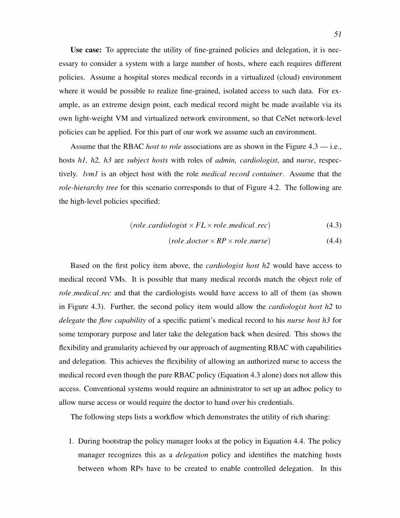
51
Use case: To appreciate the utility of fine-grained policies and delegation, it is nec-
essary to consider a system with a large number of hosts, where each requires different
policies. Assume a hospital stores medical records in a virtualized (cloud) environment
where it would be possible to realize fine-grained, isolated access to such data. For ex-
ample, as an extreme design point, each medical record might be made available via its
own light-weight VM and virtualized network environment, so that CeNet network-level
policies can be applied. For this part of our work we assume such an environment.
Assume that the RBAC host to role associations are as shown in the Figure 4.3 — i.e.,
hosts h1, h2, h3 are subject hosts with roles of admin, cardiologist, and nurse, respec-
tively. lvm1 is an object host with the role medical record container. Assume that the
role-hierarchy tree for this scenario corresponds to that of Figure 4.2. The following are
the high-level policies specified:
(role cardiologist×FL× role medical rec) (4.3)
(role doctor×RP× role nurse) (4.4)
Based on the first policy item above, the cardiologist host h2 would have access to
medical record VMs. It is possible that many medical records match the object role of
role medical rec and that the cardiologists would have access to all of them (as shown
in Figure 4.3). Further, the second policy item would allow the cardiologist host h2 to
delegate the flow capability of a specific patient’s medical record to his nurse host h3 for
some temporary purpose and later take the delegation back when desired. This shows the
flexibility and granularity achieved by our approach of augmenting RBAC with capabilities
and delegation. This achieves the flexibility of allowing an authorized nurse to access the
medical record even though the pure RBAC policy (Equation 4.3 alone) does not allow this
access. Conventional systems would require an administrator to set up an adhoc policy to
allow nurse access or would require the doctor to hand over his credentials.
The following steps lists a workflow which demonstrates the utility of rich sharing:
1. During bootstrap the policy manager looks at the policy in Equation 4.4. The policy
manager recognizes this as a delegation policy and identifies the matching hosts
between whom RPs have to be created to enable controlled delegation. In this

52
Role = admin
Role= Cardio
Role = Nurse
obj_role = medRec
SDN Controller
Capability
RBAC
RP1
2
role_cardio X flow X role_medRec
Policy
4
h1
h2
h3
S/W OVS
5
MedicalRecordServer
lvm1
role_doc X RP X role_nurse
Policy
3
Figure 4.3. CeNet rich sharing scenario
scenario, it creates an RP between the cardiologist (h2) and nurse (h3), updates their
CSpaces, and queues the capability to this new RP in their RP0s.
2. The policy manager consults the policy in Equation 4.3 and recognizes it as a flow
policy. Based on this, it creates flow capabilies to the three medical records matching
obj role = role med rec and gives them to the only subject host matching the role
cardiologist (i.e., host h2).
3. Using one of the above granted capabilities for (lvm1), cardiologist’s host h2 can
access the medical record lvm1.
4. The cardiologist wants his nurse to update a patient’s medical record. For this he
delegates the flow capability of that patient’s medical record to a nurse via the shared
RP.
5. The nurse can access the patient’s medical record via the flow capability received as
a part of the above delegation.

53
6. The doctor can later revoke the previously granted flow.
4.6 ImplementationThe policy manager sits above the capability framework on the SDN controller. Fig-
ure 4.1 shows the relative position of the policy manager with respect to the capability
system and the SDN controller. The policy manager invokes the CeNet capability API
directly as a function call (and not RPC - as is the case when hosts invoke it) to realize a
policy. The policy manager consults a policy.xml file to input the bootstrap policy.
The policy manager currently supports two policies:
The Sandbox Master policy specifies the master host and its slaves. The policy realiza-
tion in this scenario involves creating RP0s for all the hosts. In addition, node capabilities
to all the slave nodes are queued up in the master’s RP0. On booting up, the master can
use the authority of these granted capabilities to write a control-path application (next level
policy manager) using the CeNet APIs to realize a desired pattern of collaboration among
the slave nodes, or designate a submaster and so on.
<sandbox>sandbox1<name> sbox1</name>
<master>(2,1)</master>
<node>(2,2)</node>
<node>(3,1)</node>
<node>(3,2)</node>
<node>(3,3)</node>
</sandbox>
The above snippet shows a policy specification designating a master and its slaves. Note
that the tuple (x,y) in the snippet uniquely identifies the host attached to switch x’s port y
in the mininet environment.
For the RBAC policy, the parameters mentioned in Section 4.2 need to be provided as
input in the policy.xml file. A simple RBAC policy snippet related to our running example
is given below, followed by an explanation of the tags.
<rbac>
<SubjRole_Hierarchy>[("staff", "none") , ("doc", ["staff"]),
("nurse", ["staff"]), ("cardio", ["doc"]),

54
("physician", ["doc"])]</SubjRole_Hierarchy>
<SubjRole_Assocn>[((2,1), ["cardio"]),
((2,2), ["nurse"]),
((3,2), ["physician"])]</SubjRole_Assocn>
<ResourceRole_Hierarchy>[("record", "none"),("med_rec",["record"]),
("payroll_rec", ["record"])]</ResourceRole_Hierarchy>
<!-- Jithu’s medical record lies in (3,1)-->
<RsrcRole_Assocn>[(((3,1),"jithu"), ["med_rec"])]</RsrcRole_Assocn>
<policies>[("allow" , ("doc", "flow" ,((3,1),"jithu")))]</policies>
</rbac>
• Roles and role hierarchies are specified using tags < Sub jRole Hierarchy > and
< RsrcRole Hierarchy >. Note that the contents of these tags loosely encode the
hierarchy given in Figure 4.2.
• Host to role assignments are specified using tags < Sub jRole Assocn > and
< RsrcRole Assocn >
• Policies and permissions to role assignments are specified using tag < policies >.
Note that loosely encodes the relation (role doctor×FL× host (3,1)). Here, the
third parameter in this policy is very specific (i.e., it specifies a host) and not a role
like med rec as in Equation 4.3. The policy manager is flexible enough to allow
specifying either a role or a host as the third parameter of this policy.
The policy rules are composed in conjunction with the role hierarchies and role associ-
ations specified in the policy input file. The RBAC engine is based on a simple-rbac Python
library. During the policy composing and capability translation phase, for every object host
matching parameter 3 of a given policy, the above module identifies the list of matching
subject hosts. The policy manager uses this knowledge to create appropriate capabilities
(flow caps in this scenario - illustrated in Figure 4.1) to the object hosts and queue them to
the subject hosts RP0 using the capability operations discussed in the previous chapter. In
addition, the policy manager creates RP0 to all hosts.
//In the Doctor host
cap_fl,cap_type = cap.rpc_recv(cap_rp0)

55
cap.send_data_udp(cap_fl, "GET medical record")
Those matched subject hosts can now operate using those capabilities as shown above.
In this particular scenario of flow capabilities, the network switches would be configured
to route data packets carrying flow capabilities to the corresponding object hosts.
4.6.1 Evaluation
4.6.1.1 Security Properties
The network is in an off-by-default state. As explained in the RBAC policy translation
section, policy rules are composed in conjunction with role hierarchies and role associations
specified. Only explicitly allowed hosts satisfying the policy are granted flow capabilities
(allowed data path access to an object host) or given permission to delegate (by establishing
RP between hosts matching policies) to another subject host.
In addition, since all policies are translated to capability operations, at any point looking
at the CSpaces within the controller, we would be able to answer any reachability queries
at present or a later point in time.
It should be possible to identify and explore a suitable metric which can quantify the
security property better.
4.6.1.2 Ease of Use
The policy manager automates the task of realizing certain useful network access con-
trol properties as compared to the manual bootstrapping procedure. Also, as explained in
the rich sharing section, the concept of delegation allows evolution from the initial state
within the authority bounds.
Clearly we are not in a position to quantify this. It would be worthwhile to explore a
suitable metric which can quantify this property better.
4.6.1.3 Scalability
The policy manager consults the policy file, instantiates the RBAC library with the
parameters given in the input file, and identifies the matching flows and RPs to be created
to enforce the policy. This is a one-time initial overhead and is not on any critical path.
The time taken by the RBAC library to identify the matching flows and RPs based on
the policy can vary based on the number of hosts, roles, and shape of the role-hierarchy

56
tree. A small issue we faced with the library was that, while it had an interface that was
able to tell whether a given host matches a specific policy, it didn’t have an interface that
directly provided a list of all matching subject hosts (given a policy). Consequently we had
to iterate over all the subject hosts, with the first interface to obtain the desired answer.
This makes the task of identifying if a given host matches a specified policy a critical
one. Figure 4.4 shows the result of our analysis of the time taken by simple-rbac to
determine if a subject host matches a given policy or not. The time increases as we increase
the number of roles in the system.
We evaluated the worst-case time for this operation for a balanced binary tree host/role
subject hierarchy layout (with host numbers in power of 2, with upto 16,384 hosts implying
a depth of upto 14 role levels) keeping the object hierarchy tree constant. We observe that
there is a slight increase in the worst-case time to complete this operation as we increase
the number of hosts. However, for practical numbers the time per operation seems to be
well within a reasonable limit. This overhead is incurred during the bootstrap phase, not
on the critical path. It should be possible to write our own simple RBAC implementation,
which provides our required interfaces and which should be able to answer this query in
near-constant time.
The policy translation and realization involves the following additional overheads:
1. Creating flow capabilities for the matching hosts.
0 0.005 0.01 0.015 0.02 0.025 0.03 0.035 0.04 0.045 0.05
1 4 16 64 256 1024 4096 16384
Time (m
sec)
Number of roles in the system (log scale)
Figure 4.4. RBAC overhead

57
2. RPC overheads from object hosts to receive flow capabilities and invoke data trans-
fers.
RPC overhead has been studied in the end-to-end analysis (previous chapter) and pro-
vides an idea of (2). Since the RBAC engine, policy manager, and capability system are
within the SDN controller’s address space, the overhead of (1) is negligible (much less than
RPC overheads, as they are local function calls).
4.7 SummaryIn this chapter we looked at how our network is able to enforce access control according
to high-level policies by translating it into capability operations. Specifically we looked at
RBAC policy in the context of a hospital network and augmenting RBAC model with the
concept of delegation using capabilities.
The primary advantage of network enforcing policy-based access control (vs. ambient
network) is that this approach reduces the potential attack surface for a host. It also reduces
damage when a host is compromised.

CHAPTER 5
FORMAL REASONING
Capability systems allow formal reasoning about the access control allowed in a system.
In this chapter we consider how such formal reasoning would apply in the CeNet system.
Specifically, we describe the take-grant (tg) model which is a classic model used to
analyze the propagation of authority in a capability system. We capture the major results
from a formal analysis of this model. We then discuss an example scenario about how rights
propagate through a network capability system using well-defined graph transformations of
the tg model. We conclude by saying how systems based on tg model and formal analysis
give us the ability to reason about the correctness and security properties of the policy
realized.
5.1 Formal Models and SecurityIn “Formal Models of Capability-Based Protection Systems” [51], Snyder states that
protection systems are usually described informally with implementation details dominat-
ing the majority of discussions. Snyder further claims that the following pertinent questions
cannot be answered merely based on implementation details or by looking at the code.
1. Does the system actually limit access to information to those users designated by the
owner?
2. Can common sharing relationships actually be established with the given rules?
3. Under what circumstances can information be disseminated within the system?
4. What protection policy does the system implement?
A “model” favors an abstract formulation where questions similar to the above can be
precisely stated and answered. In this chapter we attempt to deviate a bit from the hitherto
implementation specific discussions and try to develop a minimal, intuitive study that aims

59
to precisely state relevant questions and hopefully answer them in the context of network
access control.
5.2 Take-Grant Modeltg protection model represents a system as a labeled directed graph whose nodes cor-
respond to entities of the protection system. The directed edge from subject s to entity
e denotes that s has α rights over e. Active entities are called subjects, passive entities
(resources) are called objects and entity means either a subject or object.
s© α−→ e©
Two special rights take (t) and grant (g) characterize this model. The meaning of these
rights are:
• Take If Subject s has take right to an entity e then it can assume any right that e has
to other entities in the system.
• Grant If Subject s has grant right to an entity e then it can transfer any right it has for
other entities to e.
The dynamic state of the system moves from one protection state to another only using a
fixed set of graph rewriting rules R. These rules transform the protection state of the system
along a sequence of graphs G0,G1, ...,Gn such that Gi follows from Gi−1 by some rule in
R. The analysis of the model focuses on answering if Gn has some particular property (like
the undesirable propagation of an access rights implying a security violation). Typically
the graph rewriting rules (governing transfer of rights) comprises of take, grant, create
and remove. Additional system specific access rights like read, right, etc., can be present.
Invoking regular access rights (like read , write) do not transform the protection graph.
5.3 Modeling CeNet SystemA capability grants some right to an object or subject (network host in our context of
network) to its owner (another network host). This can be represented as a directed graph:
A© α−→ B©
This can be interpreted as A has a capability to B with α rights. α can be a set with one or
more rights. (The single edge represents multiple capabilities if |α|> 1). For modeling our

60
system, three rights are used: R = { f low,grant, take}. The flow right gives the ability for
data transfer (A sending packets to B, through which attacker on A can try to compromise
B), while the other two rights (grant, take) are control-plane operations — explained below
— aiding in controlled sharing. Consequently, in our system, α ⊆ R for any edge. The
protection state of our overall system captures all relationships concerned with information
sharing within the network, and can be represented as a directed graph over all hosts in our
network.
To make things concrete, let us take the example of the protection state of a simplified
hospital network shown in Figure 5.1. The aim is to apply the take-grant model of rights
propagation and view the results of a formal analysis of the model in the context of network
access control. This example scenario is analogous to the computer science department ex-
ample scenario from Snyder [51], which was in the context of access to files in a computer
(with a different set of rights).
In our example scenario, the circles represent network hosts. We have the hosts of a
medical professor, student resident, radiologist, medical researcher and a Head of Depart-
RadiologistMedical Prof
Medical Researcher
Student Resident
ClinicalData
Repository
PatientHealth Record Server
PatientXray
RecordVM/Server
RadiologyArchive Server
{g}
{g}
{g}
{t}
{f}
{t}
{f}
{f,t,g}{t,g}
{f}
{f,t,g}
{f}
{f,t,g}
f = flow (data)g = grant (rp)t = take (master)
HOD (Head)
Figure 5.1. Protection graph of a simplified hospital network scenario

61
ment (HOD). In addition there are a few hosts serving data like a radiology archive server,
an X-Ray record VM server, a clinical data server, etc.
The labels indicate the rights. Note that the radiology archive host is owned by the
Radiologist and the access to this server is not shared with anyone (though rights may be
granted to the HOD). The medical prof has access to a patient’s X-ray record on an instan-
tiated file server/VM, which he later intends to share with his student resident. The access
to the X-ray record is shared with the radiologist and nobody else. The student resident
has two roles. One role is of assisting the medical professor during patient consultation
(consequently he has access to the patient health server) and the other role is that of an RA
for a research project.
The protection graph abstracts the relationship among hosts at a point in time (say, the
initial state). To answer the questions listed above, we must define the graph transformation
rules. We closely model our graph-rewriting rules along the lines of the take-grant model.
Let us look at the graph-rewriting rules allowed by our system:
• Grant: In our implementation, we call the exchange mechanism which facilitates the
grant operation the rendezvous point.
An application of the grant rule to the protection graph of Figure 5.1 would result in a
graph transformation as shown in Figure 5.2. This transformation can be interpreted
as “the medical professor grants (flow to the Xray record) to student resident.” The
effect of this operation is to establish a new sharing relationship that permits the
student resident to have data path access (flow capability) to X-Ray record VM, so
that he can do some analysis on the prof’s behalf.
• Create: An application of the create rule to the protection graph that results from the
above (grant) operation is given in Figure 5.3. This can be interpreted as “the student
resident creates/instantiates a new object/VM containing his analysis of X-Ray report
to which he has flow access.”
• Take: This operation can be invoked by a host which possesses ownership over
another host in the protection graph (in our implementation this loosely corresponds
to a node capability). An application of the take rule to the protection graph from
the above (create) operation can be considered next. This can be interpreted as “the

62
Medical professor
Student Resident
John's Xray
Record VM/Server
g { t,g,f }
g { t,g,f }
{ f }
Grant ===>
Student Resident
Medical professor
John's Xray
Record VM/Server
Figure 5.2. Grant rule applied to G0 [G0 is the Figure 5.1]. “The medical professor grants(flow to Xray record VM) to student resident.”
StudentResident
{f}Medical Opinion
Record VM
Create ==> StudentResident
Figure 5.3. Create rule applied to G1 [Figure 5.2]. “The student resident cre-ates/instantiates a new VM containing his analysis of X-Ray record to which he has flowaccess.”
medical professor takes (flow to analysis) VM from student resident to whom he had
‘ownership’.” This is given in Figure 5.4.
• Remove: This operation can remove any subset of rights from an edge on the graph.
This transformation can be initiated by node from which the edge originates.
Due to the similarities of our system with Snyder’s take-grant model, in the following
sections we attempt to summarize the main results and formal analysis of the model on his
work (but adapted to fit our network model). We treat every host in the network as a subject
and thereby effectively restricting G to a single colored graph (equivalent of saying every
host can invoke take/grant, i.e., control path APIs) whereas in their formal model they

63
Student Resident
{t,g}
{f}Med
Opinion Record
VM
Medical professor
{t,g}
{f}
{f}
take ==>
Med Opinion Record
VM
Student Resident
Medical professor
Figure 5.4. Take rule applied to G2 [Figure 5.3]. “The medical professor takes (flow toanalysis) VM from student resident (over whom he has ownership rights).”
consider two colored graphs for modeling subject and object vertices distinctively (only
subject hosts invoke take/grant operations). The results of two colored analyses would
equally hold well in our case if we were keen on having a set of hosts that are not allowed
to invoke control path APIs.
5.3.1 What Are the Questions ?
A relevant question for the professor would be
Can the X-ray record be stolen? (q.1)
The question (q.1) is a bit imprecise and we can make it more clear by asking:
“Can any host other than the medical professor or radiologist acquire a flow right to Y’s
X-ray record VM, without the professor or radiologist explicitly granting the right?” (q.2)
(q.2) puts the question in the perspective of our system and it clarifies “stolen” to mean
that another host acquires flow rights (to Y’s X-Ray record VM/server) without explicitly
receiving it from either the medical professor or the radiologist who possess that in the
original system.
We can express this more formally as: If there exists a sequence of rule applications
G0`ρ1 G1`ρ2 G2...`ρn Gn such that there is no rule ρi(1 ≤ i ≤ n) where the medical pro-
fessor or radiologist grants (flow to X-Ray report) to y for any y, and for which there is a
vertex z in Gn (other than the radiologist or professor) with an edge from z to medical-record
VM/server labeled f (flow), then X-ray record can be stolen.

64
Note that take and create make this question particularly challenging. For this particular
case the answer is no. This is because no amount of allowed rule applications can result
in another vertex (other than medical prof or radiologist) having an edge labeled flow to
X-ray record VM. But if the HOD is permitted to take information from the radiologist
(Figure 5.5) (may be intended to access some data from Radiology archive server) then Y’s
X-ray record can be stolen. A sequence of steps resulting in this is given towards the end
of section 5.3.2.
The question can be generalized as given below
can.steal(α, p,q,G)
The analogy to our example:
• α =⇒ the right being stolen (flow)
• p =⇒ the recipient of the right (the student resident, the question is: is it possible
for him to steal Y’s X-ray record)
• q =⇒ the right to whom is being stolen (X-ray record VM)
RadiologistMedical Prof
Medical Researcher
Student Resident
ClinicalData
Repository
PatientHealth Record Server
PatientXray
RecordVM/Server
RadiologyArchive Server
{g, take}
{g}
{g}
{t}
{f}
{t}
{f}
{f,t,g}{t,g}
{f}
{f,t,g}
{f}
{f,t,g}
f = flow (data)g = grant (rp)t = take (master)
HOD (Head)
Figure 5.5. Protection graph in which the X-Ray record can be stolen

65
• G =⇒ the original graph (G0 from Figure 5.1)
We want to know the conditions which can result in can.steal being true for a particular
graph G. This is crucial in answering our original questions regarding the model.
The condition of stealing is formally expressed with the help of another term can.share.
In the following section 5.3.2, we define this term, then we express the conditions which
can result in can.share being true. And finally we define can.steal formally and express
the conditions which can.steal can be true in terms of can.share.
5.3.2 Sharing and Stealing
To share some right, the recipient host first needs to acquire relevant rights to the target
host. As per our model this means that an edge from the recipient to the target must be
added to the protection graph based on a valid sequence of graph transformations.
This can be written formally as below:
can.share(α, p,q,G0). p can share (α rights to q) with someother host if and only if
there are graphs G1, ...,Gn such that
G0ρ̀1
G1ρ̀2
G2...ρ̀n
Gn
and p α−→Gn
q, which means that there is an edge from vertex p to vertex q labeled β and
α ⊆ β
We should appreciate the distinction between take and grant rights and flow rights in
our system. take and grant rights have the ability to transform the protection state of the
system (by applying the rules), whereas the flow right is of passive in nature and aids only
in data path access to a host.
We say two vertices are tg-connected if, ignoring the directionality of edges, there is a
path between them such that each edge on the path is labeled with t or g or both.
Theorem 1: can.share(α, p,q,G0) is true if and only if the following two conditions
hold true [26]:
Condition 1: There exist vertices s1, ...,su such that for each i, 1≤ i≤ u
siγi−→G0
q and α = γ1∪ ...∪ γu
Condition 2: p is tg-connected to s1, ...,su

66
Intuitively, condition 1 states that some vertex (combination of vertices) in G0 must
possess the rights to the target. Condition 2 requires the existence of paths along which
rights can be transferred from those vertices to the recipient p.
In our particular example, since the question is just about data path access to X-Ray
record VM, a single right α = f low would suffice. However for a more general case, in our
system α can be {take,grant, f low}
Discussion: In the formulation of can.share, complete cooperation from all relevant
hosts in the protection graph was assumed. But in formulating the can.steal predicate, we
assume that those possessing the rights will not cooperate in transmitting it, since otherwise
“steal” does not make sense. In other words, an owner cannot claim a capability was stolen
when he has aided in the dissemination of it [51].
can.steal(α, p,q,G0) is true if and only if !p α−→G0
q and there exist protection graphs
G1, ...,Gn such that:
1. G0`ρ1 G1`ρ2 G2...`ρn Gn
2. p α−→Gn
q
3. if s α−→G0
q, then no ρi has the form s grants (α to q) to x for any x ∈ Gi−1
Informally it means that one cannot steal a right one already owns, nor can a theft occur
if someone having the right in the initial graph grants it away.
The condition under which rights can be stolen in a protection graph can be formally
stated as:
Theorem 2: For vertices p and q in a protection graph G0 and right α , can.steal(α, p,q,G0)
is true if and only if [52]:
1. !p α−→G0
q
2. there is a subject p′ such that p = p′ or there is a tg-path between p and p′
3. there is a vertex s such that s α−→G0
q and can.share(t, p′,s,G0) is true (note that
can.share talks about t and not α)
The theorem states that the right must be stolen directly from someone possessing it. The
importance as per Snyder is that it is the only means of stealing the right.

67
The following sequence of steps tells how Y’s X-Ray record may be stolen by the student
resident in Figure 5.5.
The aim of the following sequence of operations is to set up a mail box between student
resident and medical researcher — an innocuous activity from the professor’s point of view.
1. Medical researcher creates a new object VM m (with {t,g} rights).
2. Professor takes (t to m) from research assistant.
3. Professor grants (t to m) to student resident.
comment- “steal” Y’s X-ray record.
4. HOD takes (g to m) from Medical researcher.
5. HOD takes (f to Y’s X-ray record) from radiologist.
6. HOD grants (f to Y’s X-ray record) to m.
7. Student resident takes (f to Y’s X-ray record) from m.
Discussion: From the definition of stealing, it seems the model is interested in finding
out if anyone can get rights without the owners explicitly granting the right. And from the
last theorem it looks like take/create is the path through which an unintended (nongranted)
subject is able to steal a capability. The importance as per Snyder is that it is the only means
of stealing the right. The intuitive interpretation of this theorem in a network context can
imply that a rogue admin (admin can be modeled with take) is the path through which rights
can be stolen.
The implications in network access control scenario are the following. Looking at
the SDN controller capability datastructures (the current state of protection graph), it is
possible to answer whether the network allows access between any given hosts. Further,
the model is not very rigid and allows reasonable evolution from the initial state. Again,
looking at the current state of the datastructures, the model would be able to answer whether
any transformation can ultimately result in the network allowing access between a given
pair of hosts (similar to the questions in Section 5.3.1). The model is decidable meaning it
is possible to answer these questions in finite time.

68
Further, as shown in [52], it is possible to synthesize specific systems based on the anal-
ysis. The analysis enables us to make an informed choice as to which initial configurations
to bootstrap the system into and it helps us determine what sharing can be achieved.
5.4 ConclusionIn summary we can say that a key property of take-grant capability system is the tran-
sitive, reflexive, and symmetric closure over all Grant connections. This closure provides
an authority bound which is invariant over system execution. Our bootstrap protocol is
designed based on this fact.
The theorems summarized with respect to classic TG model, especially the conditions
for can.steal(α, p,q,G0) have guided our model to be slightly different from the classic TG
model. Similar to SEl4’s modified TG system, we do not have the take-rule. This has the
advantage of giving each subject control over the distribution of its authority at the source
and we have this notion of reset operation. Removing the take rule and the addition of reset
operation/node capability (which may be interpreted as a much lighter version of take)
doesn’t invalidate the desirable properties of TG model and a strong formal analysis would
be able to provide tighter theorems in our case. We could come up with other predicates
like can.reach() which might make more sense in a network scenario.
CHAPTER 6
RELATED WORK
6.1 Capability ArchitecturesInitially formulated by Dennis and Van Horn [18], capability systems became a popular
mechanism for constructing secure, least-privilege environments in the areas of operating
systems [10, 48, 53, 54, 55] and languages [24, 56]. For many years, capability access
control was a target of misinterpretations [57, 58, 59]. The development of the object
capability model [24] revived capabilities as a viable security abstraction for constructing
least-privilege security environments [10, 16]. Miller et al. [19], and later Watson et
al. [16], provide a good discussion of the advantages of the capability model for construct-
ing practical security environments. The CeNet capability model builds on the design
principles developed by the systems research community [53, 48, 47, 60]. Similar to
seL4 [47], CeNet uses send and receive [61] to model the grant operation. Barrelfish
extends the seL4 with support for scalable capability data structures [60]. The work on
capability design patterns extends the basic capability model with the design principles
for constructing secure systems in the face of mutually mistrusting principals and diverse
security requirements [24].
Murray [62] provides an interesting discussion on principle of least authority (POLA)
versus mandatory access control (MAC) and talks about a system called PULSE - Pluggable
User-space Linux Security Environment, which implements a MAC-enforced, dynamic,
user-level POLA implementation.
6.1.1 Take-Grant Model
The need for access control management arose in the 1970s and the notion of an access
control matrix was introduced to keep track of which subjects have what types of access to
which objects. The Harrison, Russo, and Ulmann (HRU) model [63] showed in 1976 that
security is inherently undecidable in a conventional access control matrix. Specifically, for
the HRU model, the question of whether a given right can reach a given subject, for a given

70
set of macro commands, was undecidable. The underlying reason for their conclusion is the
fact that users can give away access rights on their own initiative and without constraints.
To study under what conditions it was decidable, Jones, Lipton, and Snyder developed
a model of protection called the take-grant protection model [26] in which questions of
security were not only decidable, but decidable in time linear with the number of objects
and rights [64]. Information and authority flow in the take-grant model is elegantly mod-
eled using directed graphs and can be viewed as a generalization of the transitive closure
problems [65]. The formal analysis of the TG model was studied by Snyder [51], who tries
to answer questions as done in the previous chapter of this thesis.
Initially the tg model was used to analyze the transfer of authority (rights) through the
repeated application of de jure rules - take, grant, create , and remove. These rules were
useful in studying the case where the subject acquires direct rights (authority) to access
the object (information). In 1979, Bishop and Snyder [27] added the notion of information
(versus authority) transfer to the take-grant model by creating a set of rules called de facto
rules - post, pass, spy and find rule. De facto rules are useful in studying the situation where
the subject acquires the information without necessarily being able to get direct authority to
access the information (e.g., by accessing a copy of the information with the assistance of
others). These rules represent possible information flow paths in the graph using a new type
of edge called implicit edge. Similar to can.steal and can.share from the formal analysis of
classic tg model, here we have other predicates like can.know which can reason about flow
of information. This might be a potential future exploration path in the network context for
a network with even more stringent security guarantees.
The notion of theft of rights was introduced in 1981 [66], and described how one
vertex acquires rights over another without cooperation of any owner of those rights. This
was generalized to cover the theft of information [67], and was applied to the take-grant
model to analyze a theft of information over a network [68]. This work came up with the
predicates alluded to earlier like can.steal and can.know which can be useful in our network
context as explained in the previous chapter.
Based on the TG model Shahriari [69] provides an approach to analyze network vul-
nerabilities and reason about the consequences of exploiting those vulnerabilities. Their
approach of using the take rule to model a vulnerability is quite interesting and we can use

71
a similar approach to model the effect of our administrative capability (node capability and
reset operation) and understand the security implications in the presence a rogue admin.
Australian Governments Defense Science and Technology Organization’s Annex [21]
system’s security and network architecture geared towards providing a Network Centric
Warfare (NCW) platform — that can facilitate autonomous, mutually suspicious organi-
zations to collaborate — is built on top of a distributed object-capability system. Annex
claims tight integration of their very strong security architecture with next generation net-
working technologies as a unique contribution of their work. Their capability system’s
TCB seems to have a trusted component in both the device and the network. While the
actual utility of their system was not very clear from the publication, their high level goals
seemed to be in the direction of allowing a number of mutually suspicious, autonomous
participants with differing security policies and interests to allow access to and sharing of
networked resources within a Global Information Grid. In the face of their goals, it looks
like the capability model is an apt framework for allowing collaboration among multiple
parties with different goals, and CeNet was started with the observation that capability
model can provide such similar goals (thus facilitating various interesting usecases) in a
multitenant cloud provider network. While we haven’t reached this end goal yet, this thesis
takes the first step of replacing an ambient network with a network capable of enforcing
dynamic policy driven access control (based on capability model).
6.1.1.1 Capability/Security Systems Based on the TG Model /Formal Reasoning
Summarized below are some popular systems which claim formal security as their
advantage and which frequently comes up in capability and security communities.
The Security Enhanced L4 (SEL4) model is based on capabilities and modified take-
grant model. Elkaduwe [70] prove that it is feasible to implement isolated subsystems using
seL4 mechanisms, where an isolated subsystem can be viewed as a collection of processes
or entities encapsulated in such a way that authority can neither get in nor out.
SEL4 model is slightly different from the classic TG model in that it is aimed at
reasoning over the distribution and control of physical resources like memory. They do
not use the take-rule in SEL4. This has the advantage of giving each subject control over
the distribution of its authority at the source, and they have a more complex create rule.

72
Their proof shows that the desirable properties of TG still hold and can be generalized to a
statement on full subsystems. They use Annabelle/HOL theorem prover which they claim
is better than graph transformation.
Boyton [71] extends the aforementioned formalization by Elkaduwe with nondetermin-
ism, explicit sharing of capability storage, and a delete operation for entities. He formally
proves that this new high-level access control model of the SEL4 microkernel can enforce
system-global security policies as well as authority confinement.
Sewell [36] proves that seL4 correctly enforces two high level security properties namely
integrity and authority confinement. These properties are defined with reference to a
user-supplied security policy, which specifies the maximum authority a system component
may have. The integrity property gives useful guarantee conditions for components (e.g, a
Linux guest operating system with millions of lines of code) without the need to consult
their code. Based on these guarantees we can safely and formally compose such parts with
the rest of the system.
EROS is a fast capability system for commodity processors whose higher-level security
properties are based on the diminish-take [72] model, which is a variant of TG. Several
design patterns in EROS, including confinement, protected subsystems, and user-supplied
memory managers, are formally reasoned [72] using the formal analysis of this model.
The above two works indicate that systems based on the capability model provide much
stronger security properties and much of their security claims has been formally verified.
This was a motivation for exploring this security model in the context of network access
control.
6.1.1.2 Capability/Security Systems Based on POLA
Many systems claim strong security benefits, just by removing ambient authority. In
most cases this just means disallowing global name-spaces for user processes and allowing
them to operate only on explicitly granted file descriptors (capabilities).
Plash (the Principle of Least Authority shell) [35] uses chroot() to take authority away
from a process thereby preventing it from directly accessing the normal file-system. File
descriptors to only the relevant files are then granted (like capabilities) to give only the
required limited authority back to the process. This is achieved by linking applications to
modified version of libc so that file open() operations are mediated by a trusted server that

73
performs the open operation on behalf of application as per the policy. In default mode of
operation to maintain compatibility with legacy apps, POLA is applied to files in the user’s
home directory.
CeNet proxy approach (Section 3.2.4) of seamlessly integrating legacy hosts into the
CeNet syetm is quite similar to the approach taken by plash. The proxy intercepting
protocol messages from the legacy client in CeNet system is quite analogous to the trusted
server intercepting and mediating the open syscall in plash.
By adding capability primitives to standard UNIX APIs, Capsicum [34] gives applica-
tion authors a means to realize least-privilege operation. Capsicum introduces capabilities
and a capability mode that help in compartmentalization. Capsicum capabilities are an
extension of UNIX file descriptors, and reflect rights on specific objects, such as files or
sockets. Processes in capability mode are denied access to global name-spaces such as the
file-system and PID name-spaces.
Polaris [33] is a package for Windows XP that allows users to configure the applications
they launch with only the rights they need to do the job the user wants done. A polaris con-
strained application is launched in a restricted user account with few permissions (whereas
the usual approach is to start an application using the user’s account). Authority to access
system libraries is provided to an application on startup. Also, when the the user chooses
to open a specific file, the dynamic authority to that file is provided to the application.
6.1.1.3 Access Control Policy Systems
Few systems attempt to integrate capability-based access control mechanism with other
access control models, with the aim of realizing flexible delegation and reduced admin-
istration cost. This motivation is quite similar to the utility of rich sharing scenario we
explained in 4.5.
Capability-role-based access control (CRBAC) [50] model integrates capability-based
access control mechanism into the RBAC model. It supports delegation of permissions
and roles by capability transfer, said to be useful in clinical information systems scenario.
One particular advantage they claim by basing their approach on capability model is that
cross-domain delegation can be achieved without any authentication or administrator in-
volvement. They claim that this makes flexible and smooth user-to-user delegation possible
even in unusual situations such as an emergency in clinical systems.

74
While the motivation of rich sharing scenario we explained in 4.5 is similar to CRBAC
above, the key difference is that we enforce access control in the network level and not in
an application context as done in CRBAC.This gives us the security advantage that even
when a host OS is compromised, the access control enforced by the network can play a key
role in preventing the attacker from targeting other hosts in the network.
6.2 Networks and CapabilitiesCapability concepts have been applied to networking in previous works, mostly in
the context of denial-of-service (DoS) attacks. For example, capability tokens have been
applied to the data path as a means to prevent DoS attacks [73]. In that work, senders
were required to obtain tokens (capabilities) from potential receivers, and routers in the
network were equipped to check the validity of the tokens. The capability mechanisms
used in this earlier work are quite different from the classic capability access control model
which forms the basis of our work. More recent work also proposed to deal with unwanted
traffic through capability mechanisms, but instead of issuing capabilities, proposed to use
dynamically changing IP addresses as the capabilities [74]. Superficially, this work is
related to our approach of mapping legacy protocols to capability operations in a CeNet
proxy.
In CeNet, no network communication is possible, unless explicitly allowed by a capa-
bility. As such our work is related to an earlier “off by default” approach [37]. This work
explored the feasibility of an Internet-scale reachability protocol whereby a host could
explicitly signal to the network its willingness to communicate with other hosts. Our work
in CeNet is more pragmatic in that we limit our focus to SDN networks under a single
administrative control.
The CloudPolice work [75] takes an approach that is philosophically different from our
own. For access control in cloud environments they argue that the network should not be
involved in this task at all, and that access control should be handled through hypervisor-
based mechanisms. We argue that the CeNet approach, with the network enforcing policies,
while the semantics of the policies are determined from capability enabled hosts, provides
for a partitioning of functionality that allows a unique balance of flexibility and security.
CeNet utilizes an SDN substrate and as such is related to a variety SDN related works [43,
76, 77, 44, 78, 79]. The participatory networking work [79], allows control of an SDN

75
network to be delegated to applications. This is somewhat similar to capability delegation
in CeNet. However, the PANE work is about safely delegating network control, whereas
CeNet delegates capabilities associated with network security access control.

CHAPTER 7
CONCLUSION AND FUTURE WORK
CeNet provides policy driven, fine-grained network level access control enforced in the
core of the network (and not at the end-hosts) thereby removing network ambient authority.
Thus CeNet limits the scope of spread of an attack from a compromised host to other hosts
in the network.
We built a capability enabled SDN network where communication privileges of an
endpoint are limited according to their function in the network. In pure capability mode
hosts exchange rights, establish network connections and specify access control policies
using the capability APIs which are mediated and controlled by the rules of the CeNet
capability system. Rights propagate in a capability system through well defined graph
transformations which gives us the ability to strongly reason about the correctness and
security properties of the policy realized. Further, we built a policy manager which is able
to realize a RBAC policy based network access control using capability operations. Finally
we looked at some of the results of formal analysis of capability propagation models in the
context of networks.
Thus we have proved our thesis statement “A network version of capability-based
access control can realize a more secure network by allowing only explicitly allowed
communications, and thereby removing the ambient authority present in current network
architecture. It further enables delegation oriented policies to be realized within an enter-
prise network” to be true.
7.1 Future Work• Basic networking capability: IP address and port have no relevance in a pure ca-
pability sense (and one can argue that they resemble the shared namespace which
capability literature mentions as an attack vector). It is possible to eliminate IP and
port from the packet structure and route the packet based on a flow capability which

77
would encode both the destination host and the process / socket buffer.
Our current implementation of data-path APIs send and receive data achieves this
by overloading the VLAN field to implement the flow capability, and we solely
route based on this capability. This implementation in its current form does not
consider multiprocess scenarios. One could implement a capability aware host-side
networking stack capable of demuxing the packets into multiple socket buffers based
on capabilities.
• High level policy: We explored the approach of realizing a high-level RBAC policy
based network access control, by translating it into CeNet API operations. It is
possible that other useful, high-level, policy-based network access control may be
realized via this approach of translating to this intermediate point of capability API.
Further, one could explore whether it is feasible to automate this translation from
any high level policy to capability operations. One could also look into the usability
versus security trade-off involved in manually hand-coding policy via capability API
versus using high level-policy (and translating into a capability API).
• Formal models: We can use the guarantees provided by a capability based approach
to develop tools that can answer practical questions about the guarantees of policies
in real systems.
Further, in our chapter on formal reasoning, we looked into the main results of
capability systems based on the flow of rights (de jure rules). A more stringent system
is possible based on flow of information (de facto rules). We need to understand
the utility of reasoning based on information flow in the context of networks to
understand if it makes sense in our setting. Pointers to the relevant related works
were mentioned in the previous chapter [ [27] , [67]].
• Use cases: We believe that the full blown utility of capability model is in multi-
party scenarios, for example, a cloud provider setup where multiple isolated tenants
share the cloud infrastructure, while making their own local policy decisions and
co-operating (with other untrusted tenants) in a secure manner.

REFERENCES
[1] L. Duflot and Y. A. Perez, “Can you still trust your network card?” in CanSecWest,2010.
[2] M. Egele, T. Scholte, E. Kirda, and C. Kruegel, “A survey on automated dynamicmalware-analysis techniques and tools,” ACM Comput. Surv., vol. 44, no. 2, pp. 6:1–6:42, Mar. 2008. [Online]. Available: http://doi.acm.org/10.1145/2089125.2089126
[3] F. Sang, V. Nicomette, and Y. Deswarte, “I/O attacks in intel pc-based architecturesand countermeasures,” in SysSec, 2011.
[4] H. Chen, Y. Mao, X. Wang, D. Zhou, N. Zeldovich, and M. F. Kaashoek, “Linuxkernel vulnerabilities: State-of-the-art defenses and open problems,” in APSys, 2011.
[5] N. Provos, P. Mavrommatis, M. Abu Rajab, and F. Monrose, “All Your iFRAMEsPoint to Us,” in USENIX Security Symposium, 2008.
[6] B. Yee, D. Sehr, G. Dardyk, B. Chen, R. Muth, T. Ormandy, S. Okasaka, N. Narula,and N. Fullagar, “Native client: A sandbox for portable, untrusted x86 native code,”in IEEE Symposium on Security and Privacy (Oakland’09), 2009.
[7] Bromium, “Bromium micro-virtualization,” 2010, http://www.bromium.com/innovations/micro-virtualization.html.
[8] J. Rutkowska and R. Wojtczuk, “Qubes OS architecture,” Invisible Things Lab TechRep, 2010.
[9] R. He, M. Lacoste, and J. Leneutre, “Virtual security kernel: A component-based osarchitecture for self-protection,” in Computer and Information Technology, 2010.
[10] G. Klein, K. Elphinstone, G. Heiser, J. Andronick, D. Cock, P. Derrin, D. Elkaduwe,K. Engelhardt, R. Kolanski, M. Norrish, T. Sewell, H. Tuch, and S. Winwood, “sel4:Formal verification of an os kernel,” in Proceedings of the ACM SIGOPS 22NdSymposium on Operating Systems Principles, ser. SOSP ’09. New York, NY, USA:ACM, 2009, pp. 207–220.
[11] Verizon RISK Team, “2013 data breach investigations report,” http://www.verizonenterprise.com/resources/reports/rp data-breach-investigations-report-2013en xg.pdf, 2013.
[12] Mandiant, “APT1 Exposing One of China’s Cyber Espionage Units,” http://intelreport.mandiant.com/Mandiant APT1 Report.pdf.
[13] A. Giani, V. H. Berk, and G. V. Cybenko, “Data exfiltration and covert channels,” inSPIE, 2006.

79
[14] Michael Cobb, “Advanced persistent threats: The new reality,” http://www.venafi.com/assets/pdf/APT-new-reality.pdf, 2013.
[15] ——, “How did they get in? A guide to tracking down the source of APTs,” http://twimgs.com/darkreading/advancedthreat/S4740412-howdidtheygetin.pdf, 2012.
[16] R. N. M. Watson, J. Anderson, B. Laurie, and K. Kennaway, “Capsicum: Practicalcapabilities for unix,” in USENIX Security, 2010.
[17] Citrix, “XenClient,” http://www.citrix.com/products/xenclient/how-it-works.html.
[18] J. Dennis and E. Van Horn, “Programming semantics for multiprogrammed compu-tations,” Communications of the ACM, 1966.
[19] M. Miller, K.-P. Yee, J. Shapiro, and C. Inc, “Capability myths demolished,” Tech.Rep., 2003.
[20] N. Hardy, “The confused deputy - or why capabilities might have been invented,”http://cap-lore.com/CapTheory/ConfusedDeputy.html, 1988.
[21] D. Grove, T. Murray, C. Owen, C. North, J. Jones, M. Beaumont, and B. Hopkins,“An overview of the annex system,” in Computer Security Applications Conference,2007. ACSAC 2007. Twenty-Third Annual, Dec 2007, pp. 341–352.
[22] J. Saltzer and M. Schroeder, “The protection of information in computer systems,”IEEE, 1975.
[23] M. S. Miller, C. Morningstar, and B. Frantz, “Capability-based financial instruments,”in In Proc. Financial Cryptography 2000, Anguila, BWI. Springer-Verlag, 2000, pp.349–378.
[24] M. Miller, “Robust composition: Towards a unified approach to access control andconcurrency control,” Ph.D. dissertation, Johns Hopkins University, 2006.
[25] S. Maffeis, J. C. Mitchell, and A. Taly, “Object capabilities and isolation of untrustedweb applications,” in Proceedings of the 2010 IEEE Symposium on Security andPrivacy, ser. SP ’10. Washington, DC, USA: IEEE Computer Society, 2010, pp.125–140. [Online]. Available: http://dx.doi.org/10.1109/SP.2010.16
[26] R. Lipton and L. Snyder, “A linear time algorithm for deciding subject security,”Journal of the ACM, 1977.
[27] M. Bishop and L. Snyder, “The transfer of information and authority in a protectionsystem,” in SOSP, 1979.
[28] M. Bishop, “Hierarchical take-grant protection systems,” in Operating Systems Re-view, 1981.
[29] ——, “Conspiracy and information flow in the take-grant protection model,” Journalof Computer Security, 1996.
[30] J. Shapiro and S. Weber, “Verifying the EROS confinement mechanism,” in IEEESymposium on Security and Privacy, 2000.

80
[31] G. Heiser, K. Elphinstone, I. Kuz, G. Klein, and S. Petters, “Towards trustworthycomputing systems: Taking microkernels to the next level,” Operating Systems Re-view, 2007.
[32] M. S. Miller and J. S. Shapiro, “Paradigm regained: Abstraction mechanisms foraccess control,” in Advances in Computing Science - ASIAN 2003 ProgrammingLanguages and Distributed Computation, 8th Asian Computing Science Conference,Mumbai, India, December 10-14, 2003, Proceedings, 2003, pp. 224–242. [Online].Available: http://dx.doi.org/10.1007/978-3-540-40965-6 15
[33] M. Stiegler, A. H. Karp, K.-P. Yee, T. Close, and M. S. Miller, “Polaris: Virus-safecomputing for windows xp,” Commun. ACM, vol. 49, no. 9, pp. 83–88, Sep. 2006.[Online]. Available: http://doi.acm.org/10.1145/1151030.1151033
[34] R. N. M. Watson, J. Anderson, B. Laurie, and K. Kennaway, “A taste of capsicum:Practical capabilities for unix,” Commun. ACM, 2012.
[35] M. Seaborn, “Plash: Tools for practical least privilege,” http://plash.beasts.org/environment.html, 2007.
[36] T. Sewell, S. Winwood, P. Gammie, T. Murray, J. Andronick, and G. Klein,“sel4 enforces integrity,” in Proceedings of the Second International Conference onInteractive Theorem Proving, ser. ITP’11. Berlin, Heidelberg: Springer-Verlag,2011, pp. 325–340. [Online]. Available: http://dl.acm.org/citation.cfm?id=2033939.2033965
[37] H. Ballani, Y. Chawathe, S. Ratnasamy, T. Roscoe, and S. Shenker, “Off by default!”in HotNets, 2005.
[38] D. D. Clark and S. Landau, “The problem isn’t attribution: It’s multi-stage attacks,”in ReARCH, 2010.
[39] S. Smalley, C. Vance, and W. Salamon, “Implementing SELinux as a Linux securitymodule,” NAI Labs Report, 2001.
[40] G. Faden, “Solaris trusted extensions,” Whitepaper, 2006.
[41] R. Spencer, S. Smalley, P. Loscocco, M. Hibler, D. Andersen, and J. Lepreau, “TheFlask security architecture: System support for diverse security policies,” in USENIXSecurity Symposium, 1999.
[42] M. S. Miller, J. E. Donnelley, and A. H. Karp, “Delegating responsibility in digitalsystems: Horton’s ‘Who done it ?’ ” in HotSec, 2007.
[43] M. Casado, M. J. Freedman, J. Pettit, J. Luo, N. McKeown, and S. Shenker, “Ethane:Taking control of the enterprise,” Comput. Commun. Rev., 2007.
[44] T. Benson, A. Akella, A. Shaikh, and S. Sahu, “Cloudnaas: A cloud networkingplatform for enterprise applications,” in SOCC, 2011.

81
[45] A. Belay, G. Prekas, A. Klimovic, S. Grossman, C. Kozyrakis, and E. Bugnion, “Ix:A protected dataplane operating system for high throughput and low latency,” in 11thUSENIX Symposium on Operating Systems Design and Implementation (OSDI 14).Broomfield, CO: USENIX Association, Oct. 2014, pp. 49–65. [Online]. Available:https://www.usenix.org/conference/osdi14/technical-sessions/presentation/belay
[46] S. Peter, J. Li, I. Zhang, D. R. K. Ports, D. Woos, A. Krishnamurthy, T. Anderson,and T. Roscoe, “Arrakis: The operating system is the control plane,” in 11thUSENIX Symposium on Operating Systems Design and Implementation (OSDI 14).Broomfield, CO: USENIX Association, Oct. 2014, pp. 1–16. [Online]. Available:https://www.usenix.org/conference/osdi14/technical-sessions/presentation/peter
[47] D. Elkaduwe, “A principled approach to kernel memory management,” Ph.D. disser-tation, University of New South Wales, 2010.
[48] J. S. Shapiro, J. M. Smith, and D. J. Farber, “Eros: A fast capability system,” in SOSP,1999.
[49] R. S. Sandhu, E. J. Coyne, H. L. Feinstein, and C. E. Youman, “Role-based accesscontrol models,” Computer, vol. 29, no. 2, pp. 38–47, Feb. 1996. [Online]. Available:http://dx.doi.org/10.1109/2.485845
[50] K. Hasebe, M. Mabuchi, and A. Matsushita, “Capability-based delegation model inrbac,” in Proceedings of the 15th ACM Symposium on Access Control Models andTechnologies, ser. SACMAT ’10. New York, NY, USA: ACM, 2010, pp. 109–118.[Online]. Available: http://doi.acm.org/10.1145/1809842.1809861
[51] L. Snyder, “Formal models of capability-based protection systems,” IEEETrans. Comput., vol. 30, no. 3, pp. 172–181, Mar. 1981. [Online]. Available:http://dx.doi.org/10.1109/TC.1981.1675753
[52] ——, “On the synthesis and analysis of protection systems,” SIGOPS Oper.Syst. Rev., vol. 11, no. 5, pp. 141–150, Nov. 1977. [Online]. Available:http://doi.acm.org/10.1145/1067625.806557
[53] N. Hardy, “KeyKOS architecture,” ACM SIGOPS Operating Systems Review, 1985.
[54] J. Shapiro, E. Northup, M. Doerrie, S. Sridhar, N. Walfield, and M. Brinkmann,“Coyotos microkernel specification,” The EROS Group, LLC, 0.5 edition, 2007.
[55] P. Neumann, R. Boyer, R. Feiertag, K. Levitt, and L. Robinson, A provably secureoperating system: The system, its applications, and proofs. SRI International, 1980.
[56] A. Mettler, D. Wagner, and T. Close, “Joe-e: A security-oriented subset of java,” inNDSS, 2010.
[57] W. E. Boebert, “On the inability of an unmodified capability machine to enforce the*-property,” in DOD/NBS Computer Security Conference, 1984.
[58] L. Gong, “A secure identity-based capability system,” in IEEE Symposium on Securityand Privacy, 1989.
82
[59] D. S. Wallach, D. Balfanz, D. Dean, and E. W. Felten, “Extensible security architec-tures for java,” in SOSP, 1997.
[60] M. Nevill, “An evaluation of capabilities for a multikernel,” Master’s thesis, ETHZurich, 2012.
[61] N. H. Minsky, “Selective and locally controlled transport of privileges,” ACM Trans.Program. Lang. Syst., 1984.
[62] A. P. Murray and D. A. Grove, “Pulse: A pluggable user-space linuxsecurity environment,” in Proceedings of the Sixth Australasian Conference onInformation Security - Volume 81, ser. AISC ’08. Darlinghurst, Australia,Australia: Australian Computer Society, Inc., 2008, pp. 19–25. [Online]. Available:http://dl.acm.org/citation.cfm?id=1385109.1385115
[63] M. A. Harrison, W. L. Ruzzo, and J. D. Ullman, “Protection in operating systems,”Commun. ACM, vol. 19, no. 8, pp. 461–471, Aug. 1976. [Online]. Available:http://doi.acm.org/10.1145/360303.360333
[64] J. Frank and M. Bishop, “Extending the take-grant protection system,” TechnicalReport, UC Davis, 1996.
[65] “The take-grant protection model,” in Access Control Systems. Springer US, 2006,pp. 168–179. [Online]. Available: http://dx.doi.org/10.1007/0-387-27716-1 6
[66] L. Snyder, “Theft and conspiracy in the take-grant protection model.” J.Comput. Syst. Sci., vol. 23, no. 3, pp. 333–347, 1981. [Online]. Available:http://dblp.uni-trier.de/db/journals/jcss/jcss23.html#Snyder81
[67] M. Bishop, “Theft of information in the take-grant protection model,” J.Comput. Secur., vol. 3, no. 4, pp. 283–308, Jul. 1995. [Online]. Available:http://dl.acm.org/citation.cfm?id=2699790.2699795
[68] ——, “Conspiracy and information flow in the take-grant protection model,” Journalof Computer Security, vol. 4, no. 4, pp. 331–359, 1996.
[69] H. R. Shahriari and R. Jalili, “Vulnerability take grant (vtg): An efficient approach toanalyze network vulnerabilities,” Comput. Secur., vol. 26, no. 5, pp. 349–360, Aug.2007. [Online]. Available: http://dx.doi.org/10.1016/j.cose.2007.03.002
[70] D. Elkaduwe, G. Klein, and K. Elphinstone, “Verified protection model of the seL4microkernel,” in Verified Software: Theories, Tools, and Experiments (VSTTE 2008).Toronto, Canada: Springer, oct 2008, pp. 99–115.
[71] A. Boyton, “A verified shared capability model,” in Systems Software Verification,Aachen, Germany, oct 2009, pp. 25–44.
[72] J. S. Shapiro, “The practical application of a decidable access model,” TechnicalReport, http://srl.cs.jhu.edu/pubs/SRL2003-04.pdf, 2003.
[73] T. Anderson, T. Roscoe, and D. Wetherall, “Preventing internet denial-of-service withcapabilities,” SIGCOMM Comput. Commun. Rev., 2004.

83
[74] C. A. Shue, A. J. Kalafut, M. Allman, and C. R. Taylor, “On building inexpensivenetwork capabilities,” SIGCOMM Comput. Commun. Rev., 2012.
[75] L. Popa, M. Yu, S. Y. Ko, S. Ratnasamy, and I. Stoica, “Cloudpolice: Taking accesscontrol out of the network,” in Hotnets, 2010.
[76] Z. A. Qazi, C.-C. Tu, L. Chiang, R. Miao, V. Sekar, and M. Yu, “Simple-fyingmiddlebox policy enforcement using sdn,” in SIGCOMM, 2013.
[77] A. Sayler, E. Keller, and D. Grunwald, “Jobber: Automating inter-tenant trust in thecloud,” in HotCloud, 2013.
[78] K. Beaty, A. Kundu, V. Naik, and A. Acharya, “Network-level access control man-agement for the cloud,” in IC2E, 2013.
[79] A. D. Ferguson, A. Guha, C. Liang, R. Fonseca, and S. Krishnamurthi, “Participatorynetworking: An api for application control of sdns,” SIGCOMM Comput. Commun.Rev., 2013.