centerline® 2500 motor control centers selection guide
TRANSCRIPT

CENTERLINE® 2500 MOTOR CONTROL CENTERS
SELECTION GUIDE
MOTOR CONTROL CENTERS


Product Features
General Information . . . . . . . . . . . . . . . . . . . . . . . . . . . . . . . . . . . . . . . . . . . . . . . 3
Technical Standards and Certifications . . . . . . . . . . . . . . . . . . . . . . . . . . . . . . . . . . . . . . . . . . . . . . . . 3Operating Environment . . . . . . . . . . . . . . . . . . . . . . . . . . . . . . . . . . . . . . . . . . . . . . . . . . . . . . . . . . . . . . 4Form of Separation. . . . . . . . . . . . . . . . . . . . . . . . . . . . . . . . . . . . . . . . . . . . . . . . . . . . . . . . . . . . . . . . . . . 4Mounting Configurations . . . . . . . . . . . . . . . . . . . . . . . . . . . . . . . . . . . . . . . . . . . . . . . . . . . . . . . . . . . . 5Packaging and Shipping Blocks. . . . . . . . . . . . . . . . . . . . . . . . . . . . . . . . . . . . . . . . . . . . . . . . . . . . . . . . 6
Structure. . . . . . . . . . . . . . . . . . . . . . . . . . . . . . . . . . . . . . . . . . . . . . . . . . . . . . . . . . 7
Columns . . . . . . . . . . . . . . . . . . . . . . . . . . . . . . . . . . . . . . . . . . . . . . . . . . . . . . . . . . . . . . . . . . . . . . . . . . . . 7Column Dimensions . . . . . . . . . . . . . . . . . . . . . . . . . . . . . . . . . . . . . . . . . . . . . . . . . . . . . . . . . . . . . . . . . 8Structure Material . . . . . . . . . . . . . . . . . . . . . . . . . . . . . . . . . . . . . . . . . . . . . . . . . . . . . . . . . . . . . . . . . . 10Approximate Weight. . . . . . . . . . . . . . . . . . . . . . . . . . . . . . . . . . . . . . . . . . . . . . . . . . . . . . . . . . . . . . . . 10Enclosure. . . . . . . . . . . . . . . . . . . . . . . . . . . . . . . . . . . . . . . . . . . . . . . . . . . . . . . . . . . . . . . . . . . . . . . . . . . 11Wireways. . . . . . . . . . . . . . . . . . . . . . . . . . . . . . . . . . . . . . . . . . . . . . . . . . . . . . . . . . . . . . . . . . . . . . . . . . . 12
Incoming Power . . . . . . . . . . . . . . . . . . . . . . . . . . . . . . . . . . . . . . . . . . . . . . . . . . 14
Power Bus. . . . . . . . . . . . . . . . . . . . . . . . . . . . . . . . . . . . . . . . . . . . . . . . . . . . . . . . 14
Horizontal Power Bus . . . . . . . . . . . . . . . . . . . . . . . . . . . . . . . . . . . . . . . . . . . . . . . . . . . . . . . . . . . . . . . 16Vertical Power Bus . . . . . . . . . . . . . . . . . . . . . . . . . . . . . . . . . . . . . . . . . . . . . . . . . . . . . . . . . . . . . . . . . . 17Neutral Bus . . . . . . . . . . . . . . . . . . . . . . . . . . . . . . . . . . . . . . . . . . . . . . . . . . . . . . . . . . . . . . . . . . . . . . . . 17Automatic Shutters . . . . . . . . . . . . . . . . . . . . . . . . . . . . . . . . . . . . . . . . . . . . . . . . . . . . . . . . . . . . . . . . . 18
Protective Earth Conductor . . . . . . . . . . . . . . . . . . . . . . . . . . . . . . . . . . . . . . . 18
Horizontal Protective Earth Conductor . . . . . . . . . . . . . . . . . . . . . . . . . . . . . . . . . . . . . . . . . . . . . . 18Vertical Plug-In Protective Earth Conductor . . . . . . . . . . . . . . . . . . . . . . . . . . . . . . . . . . . . . . . . . . 18
Main Incoming Compartment. . . . . . . . . . . . . . . . . . . . . . . . . . . . . . . . . . . . . 19
Main Incoming Line (Lug-Only) Compartment . . . . . . . . . . . . . . . . . . . . . . . . . . . . . . . . . . . . . . . 19Main Incoming Circuit Breaker . . . . . . . . . . . . . . . . . . . . . . . . . . . . . . . . . . . . . . . . . . . . . . . . . . . . . . 19Main Incoming Fusible Disconnect. . . . . . . . . . . . . . . . . . . . . . . . . . . . . . . . . . . . . . . . . . . . . . . . . . . 21
Door Latches. . . . . . . . . . . . . . . . . . . . . . . . . . . . . . . . . . . . . . . . . . . . . . . . . . . . . 22
Nameplates . . . . . . . . . . . . . . . . . . . . . . . . . . . . . . . . . . . . . . . . . . . . . . . . . . . . . . 22
Units . . . . . . . . . . . . . . . . . . . . . . . . . . . . . . . . . . . . . . . . . . . . . . . . . . . . . . . . . . . . 23
Unit Types . . . . . . . . . . . . . . . . . . . . . . . . . . . . . . . . . . . . . . . . . . . . . . . . . . . . . . . . . . . . . . . . . . . . . . . . . 23Module Space. . . . . . . . . . . . . . . . . . . . . . . . . . . . . . . . . . . . . . . . . . . . . . . . . . . . . . . . . . . . . . . . . . . . . . . 27Unit Design . . . . . . . . . . . . . . . . . . . . . . . . . . . . . . . . . . . . . . . . . . . . . . . . . . . . . . . . . . . . . . . . . . . . . . . . 27Withdrawable Unit Design Features. . . . . . . . . . . . . . . . . . . . . . . . . . . . . . . . . . . . . . . . . . . . . . . . . . 28Operating Handle Mechanism . . . . . . . . . . . . . . . . . . . . . . . . . . . . . . . . . . . . . . . . . . . . . . . . . . . . . . . 32Unit Disconnect Means . . . . . . . . . . . . . . . . . . . . . . . . . . . . . . . . . . . . . . . . . . . . . . . . . . . . . . . . . . . . . 33Stab Assembly . . . . . . . . . . . . . . . . . . . . . . . . . . . . . . . . . . . . . . . . . . . . . . . . . . . . . . . . . . . . . . . . . . . . . . 34Pilot Devices. . . . . . . . . . . . . . . . . . . . . . . . . . . . . . . . . . . . . . . . . . . . . . . . . . . . . . . . . . . . . . . . . . . . . . . . 36Unit Doors . . . . . . . . . . . . . . . . . . . . . . . . . . . . . . . . . . . . . . . . . . . . . . . . . . . . . . . . . . . . . . . . . . . . . . . . . 37Control Power. . . . . . . . . . . . . . . . . . . . . . . . . . . . . . . . . . . . . . . . . . . . . . . . . . . . . . . . . . . . . . . . . . . . . . 38Control Wire . . . . . . . . . . . . . . . . . . . . . . . . . . . . . . . . . . . . . . . . . . . . . . . . . . . . . . . . . . . . . . . . . . . . . . . 38Power Wire . . . . . . . . . . . . . . . . . . . . . . . . . . . . . . . . . . . . . . . . . . . . . . . . . . . . . . . . . . . . . . . . . . . . . . . . 38
Publication 2500-SG001A-EN-P—January 2008

2
IntelliCENTER® Technology . . . . . . . . . . . . . . . . . . . . . . . . . . . . . . . . . . . . . . 39
IntelliCENTER Features . . . . . . . . . . . . . . . . . . . . . . . . . . . . . . . . . . . . . . . . . . . . . . . . . . . . . . . . . . . . 39DeviceNet. . . . . . . . . . . . . . . . . . . . . . . . . . . . . . . . . . . . . . . . . . . . . . . . . . . . . . . . . . . . . . . . . . . . . . . . . . 39DeviceNet Cabling. . . . . . . . . . . . . . . . . . . . . . . . . . . . . . . . . . . . . . . . . . . . . . . . . . . . . . . . . . . . . . . . . . 40DeviceNet Cable Layout. . . . . . . . . . . . . . . . . . . . . . . . . . . . . . . . . . . . . . . . . . . . . . . . . . . . . . . . . . . . . 40DeviceNet Power Supply . . . . . . . . . . . . . . . . . . . . . . . . . . . . . . . . . . . . . . . . . . . . . . . . . . . . . . . . . . . . 40DeviceNet Scanner Modules . . . . . . . . . . . . . . . . . . . . . . . . . . . . . . . . . . . . . . . . . . . . . . . . . . . . . . . . . 41DeviceNet System Performance . . . . . . . . . . . . . . . . . . . . . . . . . . . . . . . . . . . . . . . . . . . . . . . . . . . . . . 41DeviceNet Units . . . . . . . . . . . . . . . . . . . . . . . . . . . . . . . . . . . . . . . . . . . . . . . . . . . . . . . . . . . . . . . . . . . . 41Programming of Parameters. . . . . . . . . . . . . . . . . . . . . . . . . . . . . . . . . . . . . . . . . . . . . . . . . . . . . . . . . . 42IntelliCENTER Software. . . . . . . . . . . . . . . . . . . . . . . . . . . . . . . . . . . . . . . . . . . . . . . . . . . . . . . . . . . . 42Testing. . . . . . . . . . . . . . . . . . . . . . . . . . . . . . . . . . . . . . . . . . . . . . . . . . . . . . . . . . . . . . . . . . . . . . . . . . . . . 43Software Selection . . . . . . . . . . . . . . . . . . . . . . . . . . . . . . . . . . . . . . . . . . . . . . . . . . . . . . . . . . . . . . . . . . 43
Selection Data
Column Selection . . . . . . . . . . . . . . . . . . . . . . . . . . . . . . . . . . . . . . . . . . . . . . . . 44
Incoming Power and Control Power Selection . . . . . . . . . . . . . . . . . . . . . . 46
Unit Selection . . . . . . . . . . . . . . . . . . . . . . . . . . . . . . . . . . . . . . . . . . . . . . . . . . . . 47
Incoming Main Lug Compartments and Outgoing Feeder Lug Compartments. . . . . . . . . . . 47Main Circuit Breaker Units . . . . . . . . . . . . . . . . . . . . . . . . . . . . . . . . . . . . . . . . . . . . . . . . . . . . . . . . . . 48Feeder Circuit Breaker Units. . . . . . . . . . . . . . . . . . . . . . . . . . . . . . . . . . . . . . . . . . . . . . . . . . . . . . . . . 50Main and Feeder Air Circuit Breaker Units . . . . . . . . . . . . . . . . . . . . . . . . . . . . . . . . . . . . . . . . . . . 51Direct On Line Starter Units . . . . . . . . . . . . . . . . . . . . . . . . . . . . . . . . . . . . . . . . . . . . . . . . . . . . . . . . 53Reduced Voltage Solid State (Soft Starter) Units. . . . . . . . . . . . . . . . . . . . . . . . . . . . . . . . . . . . . . . 59Variable Frequency Drive Units . . . . . . . . . . . . . . . . . . . . . . . . . . . . . . . . . . . . . . . . . . . . . . . . . . . . . . 63Unit Options . . . . . . . . . . . . . . . . . . . . . . . . . . . . . . . . . . . . . . . . . . . . . . . . . . . . . . . . . . . . . . . . . . . . . . . 69Miscellaneous Units. . . . . . . . . . . . . . . . . . . . . . . . . . . . . . . . . . . . . . . . . . . . . . . . . . . . . . . . . . . . . . . . . 72
Technical Data . . . . . . . . . . . . . . . . . . . . . . . . . . . . . . . . . . . . . . . . . . . . . . . . . . . 74
Publication 2500-SG001A-EN-P—January 2008

Product Features 3
Product Features
General Information The CENTERLINE® 2500 Motor Control Center (MCC) consists of one or more columns bolted together forming a rigid, free-standing assembly designed to allow the addition of future columns. See Figure 1.
Figure 1 CENTERLINE 2500 Motor Control Center
The MCC is designed with full isolation of electrical components from the front side of the enclosure. When doors are latched and covers are secured, a person on the operating side of the equipment is not exposed to live parts.
Units installed in MCC columns are populated with a full line of IEC components, contactors, overload relays, AC drives, soft starters and other devices.
Technical Standards and Certifications
The MCC is designed and tested to meet or exceed the requirements defined by the following IEC standards and directives.
• EN 60439-1:1999 + A1:2004, the standard for type-tested and partially type-tested assemblies of low voltage switchgear and control gear assemblies (TTA, PTA)
• EN 60204-1:1997, the general requirements for the safety of electrical equipment of machines
• 2006/95/EC, the low voltage directive• 89/336/EEC, the EMC directive as amended by 92/31/EEC and 93/68/EEC• 2002/95/EC, the restriction of hazardous substances directive (RoHS)• KEMA certified (TTA)
Publication 2500-SG001A-EN-P—January 2008

4 Product Features
The MCC columns, units and components are available with the CE Conformance Mark.
The MCC columns, units and components are available with the China Compulsory Certification (CCC).
The MCC is designed, manufactured and tested in facilities registered to ISO 9001 quality standards.
Operating Environment
The MCC is intended for use in a pollution degree 3 environment.
The MCC is designed to operate in the following ambient conditions. The ambient operating temperature shall range from -5°C to +40°C, with the average temperature in any 24 hour period not exceeding +35°C.
The MCC is designed to operate at altitudes up to 1000 m. For altitudes exceeding 1000 m, contact your Rockwell Automation representative for derating information.
Form of Separation
Internal isolation and separation exists between the following.• Individual units• Units and wireways• Units and the bus system• Wireways and the bus system
In addition, the vertical wireway for power wiring is separate from the vertical wireway for control and network wiring.
Standard internal separation within the MCC is Form 3b. Form 4b is available by enclosing terminals for external conductors in a metal box within the vertical wireway. See Figure 2.
Publication 2500-SG001A-EN-P—January 2008

Product Features 5
Figure 2 Internal Separation
Mounting Configurations
The MCC is available in two mounting configurations – front-only and double-front. See Figure 3.
• Front-only columns are joined and installed side-by-side. • Double-front columns are comprised of two separate columns joined at the rear.
Back plates are not present between the columns. The two columns have separate power bus systems providing the same phasing on units, both front and rear. Full usage of unit space is available for front and rear columns. The horizontal power bus is linked, front to rear, with a factory installed U-shaped bus splice assembly.
Figure 3 Mounting Configurations
Form 3b Form 4b
Front-Only Double-Front
Publication 2500-SG001A-EN-P—January 2008

6 Product Features
Packaging and Shipping Blocks
The MCC must remain in the upright position at all times (e.g., during transportation, storage and installation).
Figure 4 One Column Shipping Block
Standard packaging consists of columns bolted to a wooden skid with removable shipping angles and covered with a clear, plastic wrap. Heavy duty/export packaging is also available. Heavy duty/export packaging is similar to standard packaging, but the MCC is completely surrounded by wood framing and sheeting. Standard packaging and heavy duty/export packaging is not waterproof or watertight and is not intended for long-term storage.
Columns packaged for transport are considered shipping blocks. Columns are generally shipped individually, but in some instances may be joined together for ease of transportation. Shipping blocks contain continuous horizontal power bus, lifting angles, support angles and mounting channels and cannot be separated at the installation site.
Two 700 mm wide columns may be joined side-by-side and transported as a single shipping block. Up to four 700 mm columns or two 800 - 1000 mm columns in double-front configuration may be transported as a single shipping block. A single column could also be considered a shipping block. See Figure 4.
Shipping Angle(4 places)
Publication 2500-SG001A-EN-P—January 2008

Product Features 7
Structure Columns
Columns are rigid, free-standing structures with heavy duty external mounting channels continuous for the width of the shipping block. Columns are secured at the installation site by bolting through clearance holes in the mounting channels or welding.
A removable continuous steel lifting angle is provided on all shipping blocks. Two lifting angles are provided for double-front columns. See Figure 5.
Figure 5 Column Construction
Removable Top Plate
Top Horizontal Wireway Pan
Top Horizontal Wireway Barrier
Top Horizontal Wireway Cover
Vertical Wireway Door
Bottom Horizontal Wireway Cover
Right Unit Support and Vertical Wireway Assembly
Bottom Plates
Mounting Channels
Center End Closing Plate
Bottom Horizontal Wireway Closing Plates
Top Horizontal Wireway Closing Plates
Horizontal Power Bus
Left Side Plate
Control and Network Wireway
Lifting Angle
Publication 2500-SG001A-EN-P—January 2008
8 Product Features
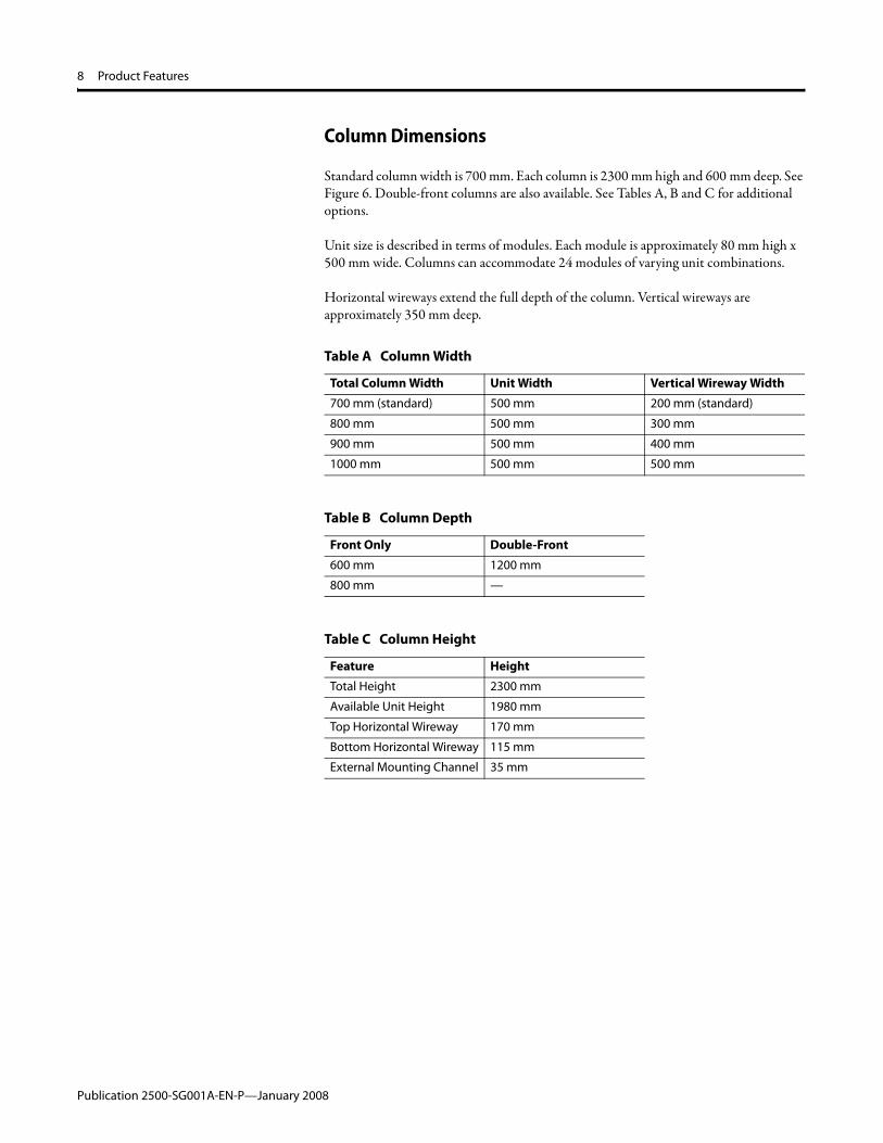
Column Dimensions
Standard column width is 700 mm. Each column is 2300 mm high and 600 mm deep. See Figure 6. Double-front columns are also available. See Tables A, B and C for additional options.
Unit size is described in terms of modules. Each module is approximately 80 mm high x 500 mm wide. Columns can accommodate 24 modules of varying unit combinations.
Horizontal wireways extend the full depth of the column. Vertical wireways are approximately 350 mm deep.
Table A Column Width
Total Column Width Unit Width Vertical Wireway Width
700 mm (standard) 500 mm 200 mm (standard)
800 mm 500 mm 300 mm
900 mm 500 mm 400 mm
1000 mm 500 mm 500 mm
Table B Column Depth
Front Only Double-Front
600 mm 1200 mm
800 mm —
Table C Column Height
Feature Height
Total Height 2300 mm
Available Unit Height 1980 mm
Top Horizontal Wireway 170 mm
Bottom Horizontal Wireway 115 mm
External Mounting Channel 35 mm
Publication 2500-SG001A-EN-P—January 2008

Product Features 9
Figure 6 Typical Column Dimensions mm (in)
170 (6.69)
1980 (77.95)
115 (4.53)
500 (19.69) 200 - 500
(7.87 - 19.69)
600 (23.62)
2300 (90.55)
35 (1.38)
700 - 1000 (27.56 - 39.37
Publication 2500-SG001A-EN-P—January 2008

10 Product Features
Structure Material
Table D lists the approximate thickness and gauge of the MCC structural components and external covers.
Approximate Weight
Table E lists approximate weights for typical MCC columns. Note that many factors (e.g. number of units, horizontal power bus rating, wireway width, column depth) affect the weight of a column. Weight is added when the product is packaged for shipping.
Table D CENTERLINE 2500 MCC Structure Details
Structural Components Thickness (mm) Approximate Gauge
Side Plate 2.0 14
Back Plate 2.5 12
Covers and Panels
Top Plate 2.0 14
Bottom Plate 2.0 14
End Closing Plate 2.0 14
Horizontal Wireway Cover 2.0 14
Doors
Unit Door 2.0 14
Vertical Wireway Door 2.0 14
Other Steel
External Mounting Channel 3.5 10
Table E Approximate Column Weight
Column Width Approximate Weight (1)
(1) Weights are for a typical Motor Control Center with 6 units per column. Weights do not include packaging. Refer to the packing slip shipped with your MCC for exact shipping weights.
700 mm 350 kg
800 mm 400 kg
900 mm 450 kg
1000 mm 500 kg
Publication 2500-SG001A-EN-P—January 2008

Product Features 11
Enclosure
Degree of Protection
In accordance with IEC 60529, enclosures are available with the following IP ratings.• IP 20 (non-filtered vented doors)• IP 30 (filtered vented doors)• IP 42 (non-vented doors, standard)• IP 54 (gasketed with bottom plates)
Enclosure metal work has rounded edges and is tightly fitted with no visible air gaps. Gasketing is made of closed cell neoprene material.
Paint and Plating
Structural metal parts undergo a multi-step cleaning, rinsing and painting process resulting in complete paint coverage of uniform thickness. The process is maintained and controlled by ISO 9001 quality standards.
Standard exterior paint color is RAL 7032 Pebble Grey. Other colors, including Munsell 6.5, are available by request.
Closing plates, channel supports, lifting angles and horizontal wireway covers are painted RAL 7021 Black Grey.
Interior vertical wireways and unit mounting plates are painted high visibility gloss white. Other colors are available by request.
Zinc with trivalent chromate is used to plate unpainted surfaces for corrosion resistance.
Publication 2500-SG001A-EN-P—January 2008

12 Product Features
Wireways
Horizontal Wireways
Horizontal wireways are located at the top and bottom of each MCC column. Horizontal wireways extend the full width and depth of the MCC. A barrier is present in the top horizontal wireway to provide a connection point for DeviceNet™ receptacles. The top horizontal wireway is 170 mm high, while the bottom horizontal wireway is 115 mm high. Complete access from front to rear is available for MCC columns configured with double-front construction.
Horizontal wireways have removable front covers that are held in place by captive screws. Openings are provided in each side plate of the column in the top and bottom horizontal wireways to allow access between joined columns. Closing plates are provided for these openings for columns located at the end of a MCC lineup. See Figure 7.
Horizontal wireways are isolated from the power bus. Horizontal wireways for incoming line sections have a reduced depth to maintain isolation from the incoming line area.
Figure 7 Top Horizontal Wireway (Covers Removed)
Vertical Wireway
The vertical wireway is located on the right side of each column and extends 1980 mm, between the top and the bottom horizontal wireway. The vertical wireway is approximately 350 mm deep. The standard vertical wireway is 200 mm wide. Vertical wireways are also available in widths of 300, 400 and 500 mm. Wider wireways are recommended for MCCs with higher bus ratings and higher unit density per section. See Figure 8.
The vertical wireway is isolated from power bus and is independent of unit space. Vertical wireways are not present in columns with fixed (frame-mounted) units.
Vertical wireways are covered with steel doors, held in place by four door latches. See Door Latches on page 22.
Vertical wireway cable supports are available.
Publication 2500-SG001A-EN-P—January 2008

Product Features 13
Figure 8 Vertical Wireway
Control and Network Wireway
A separate control and network wireway isolates control and network cables from power wiring. See Figure 9.
The control and network wireway is located on the left side of the column in the unit space. Control and network connections are made to withdrawable units through receptacles located in this wireway.
Figure 9 Control and Network Wireway
Control Wireway
Network Wireway
Publication 2500-SG001A-EN-P—January 2008

14 Product Features
Incoming Power The MCC can be configured to work on a system with any of the following incoming line voltages: 380, 400, 415, 440, 480, 600 and 690 V.
The MCC can be configured to operate at a frequency of 50 or 60 Hz.
CENTERLINE 2500 MCCs are suitable for use on three-phase, three-wire or four-wire, wye connected power systems, rated 690V or less, 50 or 60 Hz, which have a solidly grounded neutral. CENTERLINE 2500 MCCs may also be used on other power system configurators, however, some units and options may not be available. Consult the factory for additional information.
Power Bus The MCC features the time-proven Allen-Bradley CENTERLINE power bus system. The horizontal power bus is mounted near the vertical center of the structure providing optimum heat dissipation, power distribution and ease of maintenance and installation. It is mounted in recessed channels of the bus support to protect against accumulation of dust and tracking between phases. See Figure 10.
The vertical power bus allows power distribution both above and below the center-mounted horizontal bus, effectively doubling the capacity in each column. This feature also helps allow a virtually unrestricted unit arrangement.
Horizontal and vertical power bus is fastened together with a two bolt assembly. This two-bolt connection helps minimize the likelihood of “hot spots.” The factory-made horizontal to vertical power bus connection is tightened by a computerized torquing system.
The power bus system is supported, braced and isolated by a bus support molded of high strength, non-tracking glass polyester material. The horizontal power bus is mounted on-edge in a vertical plane providing maximum strength against magnetic forces. Vertical power busbars are continuously braced and sandwiched by a polycarbonate molded bus cover isolating the vertical power bus from the other vertical phases and the horizontal power bus.
Bus bracing is available with the following rms symmetrical current ratings.• 50 kA for 3 cycles at 60 Hz (standard)• 65 kA for 3 cycles at 60 Hz• 50 kA for 1 second• 50 kA for 3 seconds (horizontal power bus only)• 80 kA for 1 second (horizontal power bus only)
Publication 2500-SG001A-EN-P—January 2008

Product Features 15
Figure 10 CENTERLINE Power Bus with Neutral (Covers Removed)
Publication 2500-SG001A-EN-P—January 2008
16 Product Features
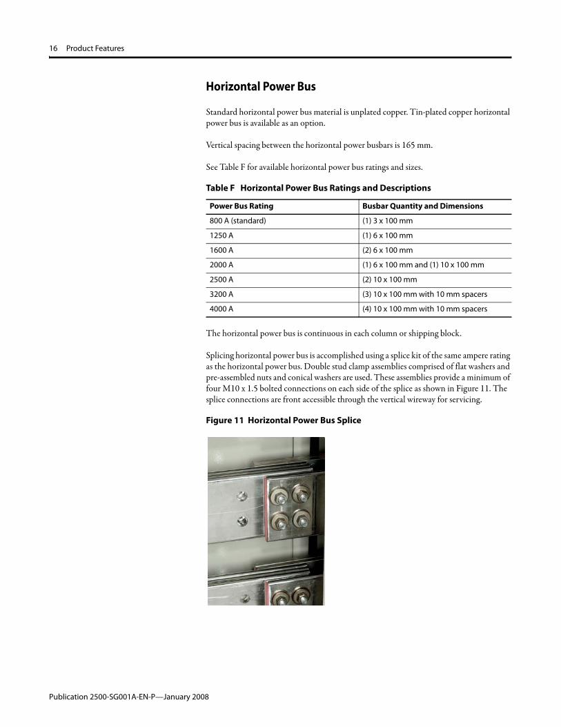
Horizontal Power Bus
Standard horizontal power bus material is unplated copper. Tin-plated copper horizontal power bus is available as an option.
Vertical spacing between the horizontal power busbars is 165 mm.
See Table F for available horizontal power bus ratings and sizes.
The horizontal power bus is continuous in each column or shipping block.
Splicing horizontal power bus is accomplished using a splice kit of the same ampere rating as the horizontal power bus. Double stud clamp assemblies comprised of flat washers and pre-assembled nuts and conical washers are used. These assemblies provide a minimum of four M10 x 1.5 bolted connections on each side of the splice as shown in Figure 11. The splice connections are front accessible through the vertical wireway for servicing.
Figure 11 Horizontal Power Bus Splice
Table F Horizontal Power Bus Ratings and Descriptions
Power Bus Rating Busbar Quantity and Dimensions
800 A (standard) (1) 3 x 100 mm
1250 A (1) 6 x 100 mm
1600 A (2) 6 x 100 mm
2000 A (1) 6 x 100 mm and (1) 10 x 100 mm
2500 A (2) 10 x 100 mm
3200 A (3) 10 x 100 mm with 10 mm spacers
4000 A (4) 10 x 100 mm with 10 mm spacers
Publication 2500-SG001A-EN-P—January 2008

Product Features 17
Vertical Power Bus
The vertical power bus material is tin-plated copper.
Vertical power bus is cylindrical, providing optimum contact with the unit plug-in stabs.
The standard vertical power bus is a copper tube rated 300 A above and below the horizontal power bus for an effective 600 A rating. An optional copper rod rated 600 A above and below the horizontal power bus for an effective 1200 A rating is available.
Horizontal spacing between the vertical power busbars is 100 mm.
Neutral Bus
The horizontal neutral bus, when specified for four-wire systems, is provided across the full width of the MCC and located above or below the horizontal power bus. Figure 12 shows a neutral bus located above the horizontal power bus.
Figure 12 Neutral Bus Located Above the Horizontal Power Bus (Back View)
The neutral bus matches the material and specifications of the vertical power bus.
The horizontal neutral bus is available with a full or half rating.
The vertical neutral bus is connected to the horizontal neutral bus and provides a neutral contact for plug-in unit stabs throughout the column.
Spacing between the horizontal power busbars and horizontal neutral busbar is 165 mm. Spacing between the vertical power busbar and vertical neutral busbar is 75 mm.
The neutral bus is braced the same way as the horizontal and vertical power bus.
Publication 2500-SG001A-EN-P—January 2008

18 Product Features
Automatic Shutters
Automatic shutters are standard on CENTERLINE 2500 MCCs. Automatic shutters open as withdrawable units are inserted and close when the unit is removed. This safety feature helps ensure that the vertical bus is immediately isolated when a withdrawable unit is removed. See Figure 13.
Figure 13 Automatic Shutters
Protective Earth Conductor
Horizontal Protective Earth Conductor
The horizontal protective earth conductor (PE) is unplated copper, or optional tin-plated copper, and is located in the bottom horizontal wireway. See Figure 14. The horizontal PE is continuous for the width of the column and is comprised of one, two or three 6 x 50 mm conductors. The horizontal PE contains 12 evenly spaced 8 mm holes along the length of the conductor for making equipment connections.
A pressure type mechanical lug is mounted on the horizontal PE conductor in the incoming line section.
Figure 14 Horizontal PE
Vertical Plug-In Protective Earth Conductor
A 6 x 32 mm unplated copper vertical plug-in PE conductor is provided in each standard column. An optional tin-plated copper vertical plug-in PE conductor is also available. The vertical plug-in PE conductor is mechanically connected to the horizontal PE conductor forming a complete internal protective earth circuit.
The vertical plug-in PE conductor in combination with the unit PE contact establishes a first make, last break operation of the PE connection with respect to power connections.
Publication 2500-SG001A-EN-P—January 2008
Product Features 19
Main Incoming Compartment
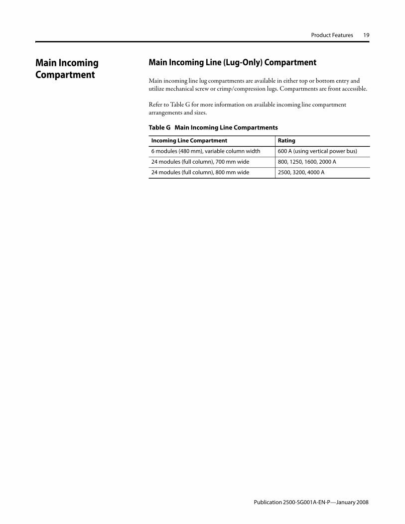
Main Incoming Line (Lug-Only) Compartment
Main incoming line lug compartments are available in either top or bottom entry and utilize mechanical screw or crimp/compression lugs. Compartments are front accessible.
Refer to Table G for more information on available incoming line compartment arrangements and sizes.
Table G Main Incoming Line Compartments
Incoming Line Compartment Rating
6 modules (480 mm), variable column width 600 A (using vertical power bus)
24 modules (full column), 700 mm wide 800, 1250, 1600, 2000 A
24 modules (full column), 800 mm wide 2500, 3200, 4000 A
Publication 2500-SG001A-EN-P—January 2008

20 Product Features
Main Incoming Circuit Breaker
Main incoming circuit breakers are available as air circuit breakers (ACB) or molded case circuit breakers (MCCB).
MCCBs are inverse time circuit breakers and can be classified as thermal magnetic or electronic.
Main circuit breaker units are front accessible and have removable protective barriers on the line side to help reduce the possibility of accidental contact with line terminals.
The ACB compartments have trip ratings available from 400 A to 4000 A. These ACBs are available with a drawout or fixed style. See Figure 15 and Figure 16. The ACBs for mains include an option to utilize 4-pole breakers. ACBs may be integrated into auto-transfer switch schemes. Refer to Table H for more information on available incoming air circuit breaker compartment arrangements and sizes. See Figure 15.
Figure 15 Fixed Style Air Circuit Breaker
Figure 16 Drawout Style Air Circuit Breaker
Table H Incoming Air Circuit Breaker Compartment Arrangement
Incoming Air Circuit Breaker Compartment Rating
24 modules (full column), 800 mm deep x 800 mm wide 800, 1250, 1600, 2000 A
24 modules (full column), 800 mm deep x 900 mm wide 2500, 3200, 4000 A
Publication 2500-SG001A-EN-P—January 2008

Product Features 21
Figure 17 Air Circuit Breaker, Drawout Style Shown
Main Incoming Fusible Disconnect
Mains with fusible disconnects are available. Fuses can be factory installed, or supplied and installed by others.
Publication 2500-SG001A-EN-P—January 2008

22 Product Features
Door Latches Latches are provided on unit and vertical wireway doors to hold the door closed and isolate the column. Door latches can be locked or released by rotating the latch ¼ turn. An arrow on the door latch head indicates the position of the latch.
Optional arc containment latches are available for doors. Arc containment latches help protect personnel in the vicinity of the MCC if an arc fault occurs when enclosure doors are closed and latched. Arc containment latches can be locked or released by rotating the latch ¼ turn. See Figure 18.
Figure 18 Arc Containment Latch
For additional service access, an optional rear enclosure door with 3-point latch (up to IP 54 degree of protection) will be available as a future option.
Nameplates The MCC master nameplate, when specified, is located on the top horizontal wireway cover.
The MCC master nameplate is 160 mm x 50 mm with black lettering on a white background. The nameplate can have up to five lines of engraving.
Unit nameplates are available. Nameplate dimensions are 92 mm x 28 mm and can accommodate three or four lines of engraving. The following types of name plates are available. See Figure 26.
• Clear cardholders - insert printed cards into cardholder.• Engraved acrylic nameplates - white with black lettering or black with white
lettering.• Engraved phenolic nameplates - white with black lettering, black with white
lettering or red with white lettering.
Nameplates are secured using two steel self-tapping screws. Stainless steel screws are available.
Figure 19 Unit Nameplate (Acrylic)
Publication 2500-SG001A-EN-P—January 2008
Product Features 23
Units Unit Types
Columns can be populated with several different types of units, including mains, feeders, direct on line starters and contactors (e.g., direct on line non-reversing, direct on line reversing, star/delta, two-speed one winding, two-speed two windings, lighting contactors), reduced voltage solid-state starters (soft starters), AC drives and PLCs. Figure 20 shows a one module unit.
Figure 20 One Module Unit
Main and Feeder Units
Incoming Main Lug Compartments and Outgoing Feeder Lug Compartments
The line lug compartments provide a lug connection for incoming lines (mains) to distribute power to the Motor Control Center or for outgoing cables (feeders) to feed power from the Motor Control Center to an external load. These line lug compartments are available with ratings from 300 A to 4000 A in a fixed mount style of unit.
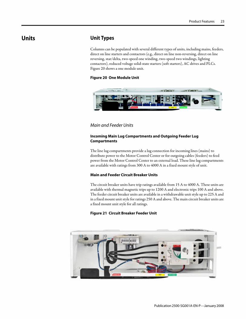
Main and Feeder Circuit Breaker Units
The circuit breaker units have trip ratings available from 15 A to 4000 A. These units are available with thermal magnetic trips up to 1200 A and electronic trips 100 A and above. The feeder circuit breaker units are available in a withdrawable unit style up to 225 A and in a fixed mount unit style for ratings 250 A and above. The main circuit breaker units are a fixed mount unit style for all ratings.
Figure 21 Circuit Breaker Feeder Unit
Publication 2500-SG001A-EN-P—January 2008

24 Product Features
Starter Units
Direct On Line Non-reversing Starter Units
These combination direct on line non-reversing starter units are supplied with Allen-Bradley Bulletin 100C or 100D contactors and either a fusible disconnect or circuit breaker. These units are available with a eutectic E1 Plus or E3 Plus overload relay and available with or without an external reset button for the overload relay. These units are available in a withdrawable unit style and a fixed unit style.
Figure 22 Combination direct on line non-reversing starter unit
Direct On Line Reversing Starter Units
These combination direct on line non-reversing starter units are supplied with Allen-Bradley Bulletin 104C or 104D contactors and either a fusible disconnect or circuit breaker. The starters are mechanically and electrically interlocked to avoid both contactors being closed simultaneously. These units are available with an E1 Plus or E3 Plus overload relay and available with or without an external reset button for the overload relay. These units are available in a withdrawable unit style and a fixed unit style.
Figure 23 Combination direct on line reversing starter unit
Publication 2500-SG001A-EN-P—January 2008

Product Features 25
Reduced Voltage Solid State Units (Soft Starters)
Reduced voltage solid state units, also referred to as soft starter controller units, are designed especially for use in CENTERLINE 2500 Motor Control Centers. Each unit contains a microprocessor-controlled motor controller, control circuit transformer and either a fusible disconnect switch or circuit breaker. These units are available in a withdrawable unit style and a fixed unit style. SMC-3 Smart Motor Controller features include:
• Three starting modes: soft start, kick start and current limit• Electronic overload protection with selectable overload trip class• Motor and system diagnostics• Soft stop• Integrated bypass contactor
SMC-Flex Smart Motor Controller features include:• Seven standard modes of operation: soft start, current limit start, dual ramp, full
voltage, linear speed acceleration, preset slow speed and soft stop• Optional modes of operation: pump control, Smart Motor BrakingTM,
Accu-StopTM and slow speed with braking• Integral SCR bypass• Electronic overload protection with selectable overload trip class• Full metering and diagnostics• DPI communication
Figure 24 SMCTM -Flex
Publication 2500-SG001A-EN-P—January 2008

26 Product Features
Variable Frequency Drive Units
PowerFlex® Adjustable Frequency AC Drives
The combination variable frequency AC drive units are specifically designed for use in the CENTERLINE 2500 Motor Control Centers. Each unit contains a variable frequency AC drive and either a fusible disconnect switch or circuit breaker. These units are available in a withdrawable unit style and a fixed unit style. Available models include:
• PowerFlex 40 Adjustable Frequency AC drive• PowerFlex 70 Adjustable Frequency AC drive• PowerFlex 700 Adjustable Frequency AC drive
PowerFlex drive features include:• Isolated logic and power• Produce a three-phase, pulse width modulated (PWM) adjustable frequency
output and voltage output for exceptional control of motor speed and torque• Are digitally programmed with access to mode programming, providing precise
and repeatedly accurate setup, control and operation, and adaptability to handle a variety of applications
Figure 25 PowerFlex 70 Adjustable Frequency AC drive
Publication 2500-SG001A-EN-P—January 2008

Product Features 27
Module Space
Unit size is described in terms of modules. One module is approximately 80 mm high x 500 mm wide. Withdrawable units are available in the following sizes: 1, 2, 4, 6, 8, 10 and 12 modules. Fixed units range in size from 2 to 24 modules. Figure 26 shows an eight module unit.
Each MCC column can accommodate 24 modules.
Figure 26 Eight Module Unit
Unit Design
Units are designed as either withdrawable or fixed. Withdrawable units have a maximum current rating of 225 A.
The amount of current drawn by fixed units is determined by the rating of the horizontal power bus. Fixed units are frame-mounted and cannot be moved or rearranged once installed in the column. Figure 27 shows a two module unit.
Figure 27 Two Module Unit
Publication 2500-SG001A-EN-P—January 2008

28 Product Features
Withdrawable Unit Connections
Withdrawable units are characterized by withdrawable line, load, control, network and protective earth (PE) connections. Outgoing load and control connections are in the vertical wireway.
Fixed (Frame-Mounted) Unit Connections
In fixed units, line, load, PE and control connections are made directly to components. Network connections can be made through fixed or plug-in terminal blocks. Table I shows possible unit connections.
Withdrawable Unit Design Features
Withdrawable units consist of the unit, unit support pan and unit door. Withdrawable units are held securely in the column when inserted and are designed with an interlock to help ensure that units cannot be inserted or withdrawn when the disconnect means is in the ON/I position. Withdrawable units range from 1 up to 12 module sizes.
Tools are not required to insert or remove withdrawable units.
Fixed (Frame-Mounted) Unit Design Features
Fixed units are permanently mounted in the column, all connections are made directly to the components. Fixed units range from 2 up to 24 module sizes.
Withdraw Lever and Alignment Slides
Withdrawable units utilize low friction alignment slides and a mechanical withdraw lever for ease of insertion and removal. The withdraw lever features a locking mechanism that must be disengaged to change positions. Detents are present to help confirm that the unit is secured in one of the operating positions. See Figure 28 and Figure 29.
Table I Unit Connections
Withdrawable Unit Connections
Fixed Unit Connections
Line Withdrawable Fixed
Load Withdrawable Fixed
PE Withdrawable Fixed
Control Withdrawable Fixed
Network Withdrawable Disconnectable
Publication 2500-SG001A-EN-P—January 2008

Product Features 29
Figure 28 Withdraw Lever
Figure 29 Unit Support Pan With Alignment Slides
Publication 2500-SG001A-EN-P—January 2008
30 Product Features
Operating Positions
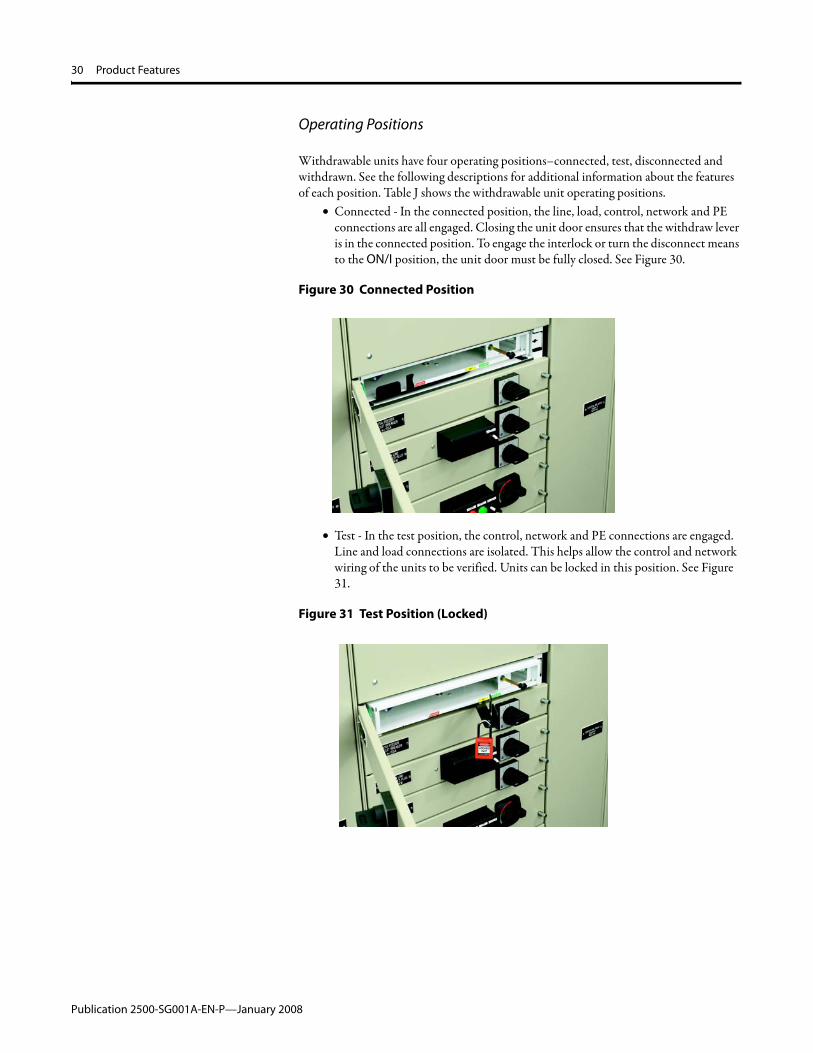
Withdrawable units have four operating positions–connected, test, disconnected and withdrawn. See the following descriptions for additional information about the features of each position. Table J shows the withdrawable unit operating positions.
• Connected - In the connected position, the line, load, control, network and PE connections are all engaged. Closing the unit door ensures that the withdraw lever is in the connected position. To engage the interlock or turn the disconnect means to the ON/I position, the unit door must be fully closed. See Figure 30.
Figure 30 Connected Position
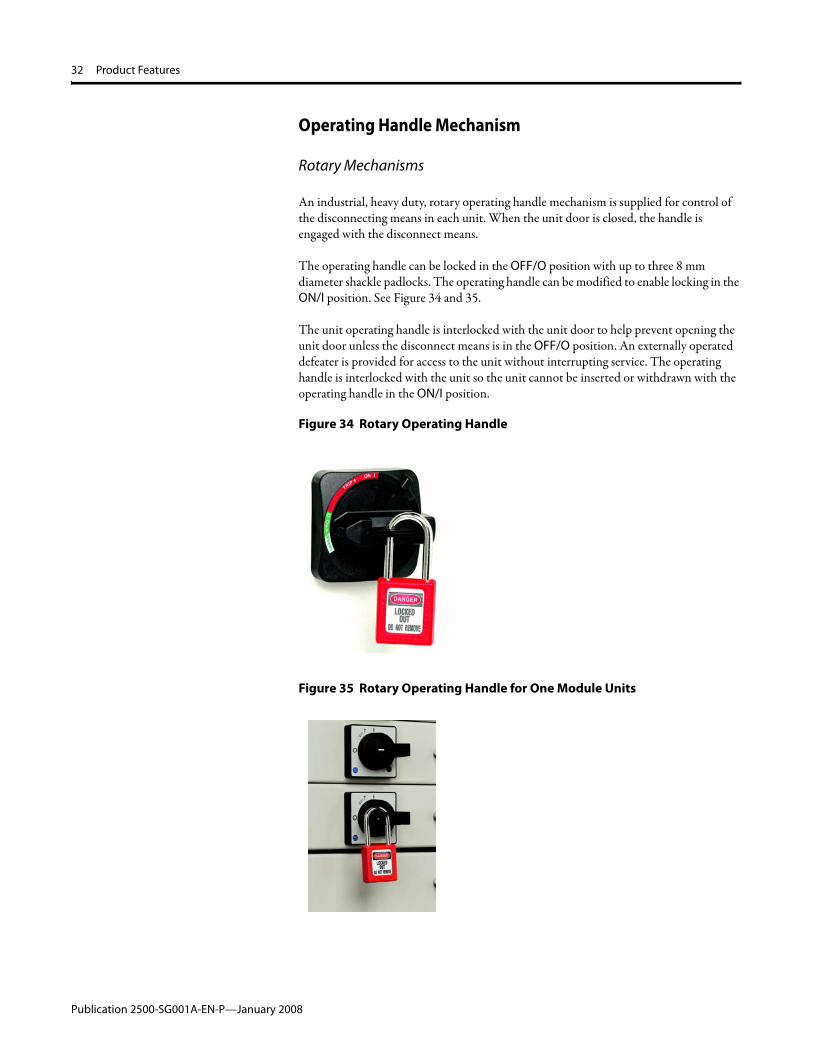
• Test - In the test position, the control, network and PE connections are engaged. Line and load connections are isolated. This helps allow the control and network wiring of the units to be verified. Units can be locked in this position. See Figure 31.
Figure 31 Test Position (Locked)
Publication 2500-SG001A-EN-P—January 2008

Product Features 31
• Disconnected - In the disconnected position, the unit remains housed in the column, but connections are not present. This is an isolated position. Units can be locked in the disconnected position. See Figure 32.
Figure 32 Disconnected Position (Locked)
• Withdrawn - Withdrawable units can be completely removed from the columns. When units are withdrawn from the MCC, they are isolated from connections. Withdrawn units can be locked to prevent insertion. See Figure 33.
Figure 33 Withdrawn Position
Table J Withdrawable Unit Operating Positions
Operating Position
Connection Present Lockable in Position
Line Load PE Control Network
Connected x x x x x x(1)
Test x x x x
Disconnected Connections not present. Unit remains inserted in column. x
Withdrawn Connections not present. Unit is removed from column. x
(1) Unit is lockable when door is closed.
Publication 2500-SG001A-EN-P—January 2008
32 Product Features
Operating Handle Mechanism
Rotary Mechanisms
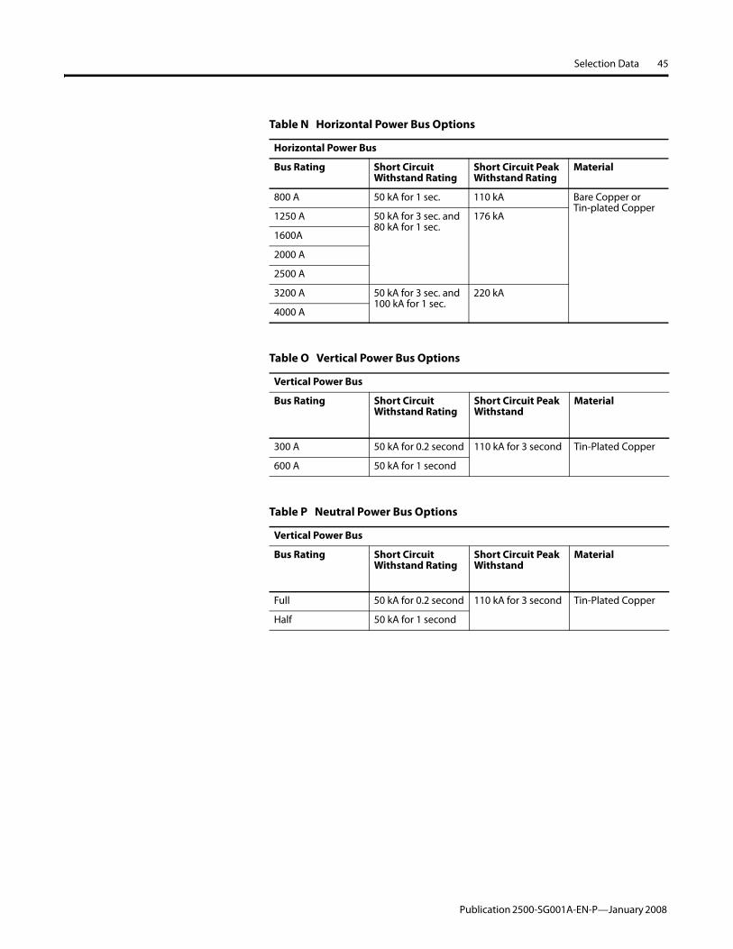
An industrial, heavy duty, rotary operating handle mechanism is supplied for control of the disconnecting means in each unit. When the unit door is closed, the handle is engaged with the disconnect means.
The operating handle can be locked in the OFF/O position with up to three 8 mm diameter shackle padlocks. The operating handle can be modified to enable locking in the ON/I position. See Figure 34 and 35.
The unit operating handle is interlocked with the unit door to help prevent opening the unit door unless the disconnect means is in the OFF/O position. An externally operated defeater is provided for access to the unit without interrupting service. The operating handle is interlocked with the unit so the unit cannot be inserted or withdrawn with the operating handle in the ON/I position.
Figure 34 Rotary Operating Handle
Figure 35 Rotary Operating Handle for One Module Units
Publication 2500-SG001A-EN-P—January 2008

Product Features 33
Flange Mechanisms
Flange style disconnect handles (vertical or horizontal) are available for units with circuit breaker disconnects. The flange handle helps prevent the disconnect means from being switched to the ON/I position while the unit door is open. See Figure 36.
Figure 36 Vertical Flange Operating Handle
Units with vertical flange handles must be at least 4 modules. Units with horizontal flange handles must be at least 2 modules.
Unit Disconnect Means
The unit main switch is available as a circuit breaker or disconnect.
Withstand ratings for combination starter units are based on the short circuit protective devices and components selected.
Circuit Breakers
Allen-Bradley circuit breakers are provided as the disconnecting means for units specified with a circuit breaker unit main switch. Bulletin 140M motor circuit protectors are used for combination motor control units. Bulletin 140M motor protection circuit breakers and Bulletin 140U molded case circuit breakers are utilized for feeder units.
Circuit breaker unit main switches are available in the following ratings based on circuit breaker and component selection. See Table K.
Table K Circuit Breaker Ratings
Rating Amperage and Voltage
Type 1 Up to 100 kA at 400 V
Type 2 Up to 65 kA at 400 V
Up to 50 kA at 500 V
Up to 25 kA at 600 V
Up to 10 kA at 690 V
Publication 2500-SG001A-EN-P—January 2008

34 Product Features
Disconnect Switches
When specified, Allen-Bradley disconnect switches are provided. The Bulletin 194R fused disconnect switch is used in combination starter and feeder units. One module combination starter and feeder units utilize the Bulletin 194E unfused switch.
When requested, NH fuses are supplied in the following styles: DIN gG and DIN aM. Fuse selection will be expanded to include BS-88, French Ferrule and international style fuses as a future option.
Disconnect unit main switches are available in the following ratings based on component and fuse selection. See Table L.
Stab Assembly
Power Stab Assembly
The two-piece stab housing is made of high strength, non-tracking glass polyester material and provides a separate isolated pathway for each phase.
The power cable connection at the plug-in stab is made with a maintenance free crimp style connection. There is no exposed wiring at the back of the unit between the disconnecting means and the plug-in stabs. See Figure 37.
Figure 37 Power Stab Assembly
Unit plug-in power stabs are free-floating and self aligning.
Unit plug-in power stabs are rated 225 A. The stabs are made of tin-plated copper for a low resistance connection and are designed to tighten during heavy current surges.
Table L Disconnect Ratings
Rating Amperage and Voltage(1)
(1) For 690V information, please consult the factory.
Type 2 Up to 100 kA at 400 V
Up to 100 kA at 500 V
Up to 100 kA at 600 V
Publication 2500-SG001A-EN-P—January 2008

Product Features 35
Unit plug-in power stabs are backed by stainless steel spring clips to provide and maintain a high pressure, four-point connection to the vertical power bus.
Neutral Stab Assembly
The neutral stab assembly can be supplied on withdrawable units when a 4-wire system is required. The neutral stab assembly has the same design and features as the power stab assembly, but is a separate piece. See Figure 38.
Figure 38 Neutral Stab Assembly
One Module Stab Assembly
The one module stab assembly consists of a receptacle for line and load connections that plugs into a subplate connected to the vertical power bus. Two guide pins help ensure that the connector is properly aligned. Because of the subplate connection, one module units must be installed in pairs.
One module units stabs are rated at 32 A. See Figure 39.
Figure 39 One Module Stab Assembly
Publication 2500-SG001A-EN-P—January 2008

36 Product Features
Protective Earth Contact
An unplated copper PE contact is provided on withdrawable units. This contact establishes a connection with the PE circuit before other connections are made and is the last withdrawable connection to be disconnected. See Figure 40.
Control and Network Connections
Plug-in control and network connections are made automatically for withdrawable units. A 15-pin connector plug, rated at 10 A, is used for control connections. DeviceNet network connections are made through a separate connector. The control and network connectors are assembled in a spring-loaded mechanism. See Figure 40.
Figure 40 PE Contact, Control and Network Connections
Pilot Devices
Pilot devices are housed in door mounted control station. See Figure 41. Each control station can accommodate up to four 22 mm devices. Multiple control stations can be mounted on a unit door, if more than four pilot devices are required.
Control stations are equipped with a quick connect plug for ease in connecting and disconnecting control wiring.
Publication 2500-SG001A-EN-P—January 2008

Product Features 37
The control station is easily removed using captive screws. If a control station is removed, closing plates are available to cover the opening in the unit door and provide isolation.
Figure 41 Control Station and Pilot Devices
Unit Doors
Each unit is provided with a removable unit door mounted on removable pin type hinges. Unit doors are held closed with ¼ turn latches. See Door Latches on page 22.
It is not necessary to remove a unit door when installing or removing units. The unit door is fastened to the structure so it can be closed to isolate the power bus when the unit is removed. The unit door can be removed from any location on the MCC without disturbing other unit doors.
Control stations for pilot devices and low profile external reset buttons for overload relays are often mounted to the unit door. See Figure 42.
Figure 42 Unit Doors
Publication 2500-SG001A-EN-P—January 2008

38 Product Features
Control Power
Unit control power is specified as one of the following voltages: 24 VDC, or 110, 115, 120, 220, 230, or 240 VAC.
Unit control power is normally supplied by a single common control power transformer unit within each MCC lineup. Common control power allows the test function of withdrawable units to work most effectively. The common control source operates at line voltage with an option for common control fusing.
Individual control circuit transformers, mounted in each unit, are available. One leg of the secondary side of the control circuit transformer is fused while the other leg is connected to PE. Primary protection is provided by primary fusing.
Control Wire
Standard control wire for units is copper, 1.5 mm2, 90°C.
Wire markers are available.
Power Wire
Power wire is copper and rated for a minimum of 105°C. The power wire is sized to meet the current rating of the unit, with a minimum size of 6 mm2.
Publication 2500-SG001A-EN-P—January 2008

Product Features 39
IntelliCENTER® Technology
IntelliCENTER Features
Built-in Networking
• Media protected behind barriers• Access ports in wireways• Trunk and Drop topology allows for addition and removal of devices without
shutting down the network
Intelligent Motor Controls
• PowerFlex Drives• SMC-3 and SMC-Flex Soft Starters• E1 Plus, E3 Plus Electronic Overload relays• DeviceNet Starter Auxiliaries
IntelliCENTER Software
• Elevation View• Monitor View• Documentation Views
Factory Configuration
• Network media validation• Node configuration• Device communication check
DeviceNet
DeviceNet is a robust communication link that connects industrial devices (such as limit switches, photoelectric sensors, motor starters, push buttons, variable frequency drives, and operator interfaces) to a network and eliminate time-consuming and costly hardwiring. DeviceNet is a simple, open networking solution based on the producer/consumer model, the latest in network technology. This technology allows for real-time control, data exchange, configuration capabilities, and collection of data at regular intervals or on demand. The network specifications and protocol are open—managed by the Open DeviceNet Vendor Association (ODVA)—meaning that vendors are not required to purchase hardware, software, or licensing rights to connect devices to a system. Over 300 vendors offer DeviceNet products with over a half million installed nodes worldwide.
DeviceNet in MCCs
DeviceNet is ideally suited for MCC applications for cost and performance. This document details the applications of DeviceNet in MCCs, including cable system construction and common DeviceNet components.
Publication 2500-SG001A-EN-P—January 2008

40 Product Features
DeviceNet Cabling
All trunk and drop cabling is ODVA certified Class 1, with 600V insulation and 8 A rating. Additionally, the IntelliCENTER DeviceNet cabling system has been extensively tested for noise immunity with network cables in close proximity to high current motor leas and VFD outputs. As a result, IntelliCENTER MCCs provide a very robust network solution with no special separation, barriers, or internal conduit required.
DeviceNet Cable Layout
The DeviceNet trunk line is routed through the control and network wireway and top horizontal wireway of the MCC. See Figure 43. Trunk lines are routed behind barriers that isolate the cable from the unit space and wireways to help prevent accidental damage during MCC installation.
Figure 43 DeviceNet Trunk Line
Up to 24 DeviceNet ports can be provided in the control and network wireway. Each DeviceNet component in an MCC unit is connected to a DeviceNet port located in the control and network wireway. The addition or removal of a unit from the DeviceNet system does not interrupt the operation of other units in the system.
DeviceNet Power Supply
The DeviceNet system within the MCC requires a power supply that provides 24 VDC rated no less than 8 A.
Selection of a quality power supply is essential for reliable system operation. To ensure integrity, the Allen-Bradley Bulletin 2100-DPS 8 A DeviceNet Power Supply unit is recommended. This power supply conforms to DeviceNet requirements, has the ODVA checkmark, and is supplied with a buffer for enhanced ride-through performance. A redundant power supply is also available for added reliability.
Publication 2500-SG001A-EN-P—January 2008

Product Features 41
DeviceNet Scanner Modules
The DeviceNet system in the MCC requires a DeviceNet scanner module that conforms to DeviceNet requirements. The scanner module may be located in the MCC or mounted remotely.
As an alternative to a DeviceNet scanner module located in the PLC, linking devices can be used to link different communication networks to the MCC DeviceNet system (such as linking ControlNet to DeviceNet, or EtherNet/IP to DeviceNet). NetLinx technology enables the user to “route” from one network to another very easily, which makes the task of moving data from the MCC’s DeviceNet onto the controller’s EtherNet/IP or ControlNet simple
DeviceNet System Performance
The DeviceNet system in the MCC is designed to operate at 500 kbaud to maximize performance, unless precluded by the cumulative length of the trunk and drop lines. To achieve best performance, all MCCss are engineered for a 250 kbaud minimum communication rate.
The DeviceNet system in the MCC is qualified to communicate and perform under normal and adverse electrical environments (for example, contactor electrical operation, contactor jogging duty and unit short circuit fault).
The DeviceNet system has the following capabilities:• Automatic Device Replacement (ADR).• On-Line Scanlist Changes at Run, allowing network modifications to be
performed on a DeviceNet system that is running.• Scan modes: Polled, Change of State (COS), Strobe and Cyclic. By choosing the
appropriate scan mode for different data, DeviceNet systems can achieve better throughput performance than networks with much higher baud rates.
• Transmit and receive data via I/O and explicit messaging. This allows the control system to access every parameter in the device, not just a few registers.
DeviceNet Units
Each unit can be provided with a DeviceNet component. • Starter units can be provided with an E1 Plus with DeviceNet module, E3 or E3
Plus overload relays or solid-state overload relays with a DeviceNet Starter Auxiliary.
• Contactor units can be provided with a DeviceNet Starter Auxiliary. • AC drives can be provided with a DeviceNet communication module. • Solid-state controllers can be provided with DeviceNet communication modules
and, in some instances, a DeviceNet Starter Auxiliary. • Fusible disconnect and circuit breaker feeder circuits can be provided with a
DeviceNet Starter Auxiliary.
Publication 2500-SG001A-EN-P—January 2008

42 Product Features
Programming of Parameters
The DeviceNet node address is programmed for each unit. All other parameters are left at the factory default setting.
The DeviceNet components are configured to operate at the specified baud rate.
IntelliCENTER Software
The MCC can be provided with pre-configured IntelliCENTER software. The software is capable of viewing multiple MCC line-ups. The IntelliCENTER software communication driver lets the software be installed and operated on Ethernet, ControlNet, or DeviceNet. The IntelliCENTER software is capable of functioning as a stand alone software package or as an ActiveX control in a Human Machine Interface (HMI). The IntelliCENTER software can display the following:
• Elevation View– Dynamically displays status information based on reading data from devices in
MCC line-up– Sizeable view to allow ease of viewing multiple MCC line-ups– Unit nameplate information– Unit status indicators (ready, running, warning, fault, no communication)
• Unit Monitor View– Pre-configured for a specific unit– Real-time monitoring via analog dials and trending– Data configurable for customized viewing– Modifying device parameters
• Spreadsheet View– User configurable for customized monitoring– Sorting and cascading functions– Custom user fields
• Event Log– Track history of MCC unit– Automatic logging of trips, warnings and changes– Manual entry of events
• Documentation– Front elevation drawings– Unit wiring diagrams– User manuals– Spare parts lists
Publication 2500-SG001A-EN-P—January 2008

Product Features 43
Testing
Motor control centers with DeviceNet are powered up, configured and tested to ensure each unit communicates properly.
For more information on MCCs with DeviceNet, refer to publication 2500-TD002x-EN-P, CENTERLINE 2500 DeviceNet Motor Control Centers.
Software Selection
IntelliCENTER Application Software
Application that serves as the user interface to the IntelliCENTER MCC. One license is required for every PC that IntelliCENTER will be installed on. One IntelliCENTER application can view any number of IntelliCENTER MCC databases. IntelliCENTER Application Software is available in Full or ActiveX Only Versions. The Full Version operates as a stand-alone package, offering full functionality on a PC. The ActiveX Only version provides the ActiveX controls used in each IntelliCENTER view. This version is well suited for installing IntelliCENTER functionality on the system’s HMI computers. (One Full Version is required for programming and administration of IntelliCENTER database files).
IntelliCENTER Database
The IntelliCENTER Database contains all of the order-specific information that the IntelliCENTER application software needs to represent the MCC. One IntelliCENTER Database is required for each MCC lineup, or for individual units when the unit is purchased separately. The database is installed on the PC(s) running the IntelliCENTER application, or on a central server. The database CD includes the IntelliCENTER data files, all of the electronic documentation (such as wiring diagrams, user manuals, and spare parts lists), all up-to-date EDS files for the DeviceNet devices, and the DeviceNet configuration file (.DNT) as recorded during the final system test of the MCC. The EDS and .DNT files are also very useful for programming the control system, allowing the programmer to complete the project even before the equipment is energized. Additionally, when used with RSLogix 5000 and RSNetworx for DeviceNet software, the programmer can use the DeviceNet Tag Generator utility in RSLogix 5000 to instantly generate descriptive tags for every device in the MCC.
Publication 2500-SG001A-EN-P—January 2008

44 Selection Data
Selection Data
Column Selection The following tables outline the CENTERLINE 2500 MCC product offering. Please select your columns and unit types.
Figure 44 Column Dimensions mm (in)
170 (6.69)
1980 (77.95)
115 (4.53)
500 (19.69) 200 - 500
(7.87 - 19.69)
600 (23.62)
2300 (90.55)
35 (1.38)
700 - 1000 (27.56 - 39.37
Table M Column Options
Column Type Width Depth Height IP Rating Separation
Withdrawable Units 700 mm (200 mm wireway) 600 mm
800 mm
1200 mm (double-front)
2300 mm IP 20
IP 30
IP 42
IP 54
Form 3b
Form 4b800 mm (300 mm wireway)
900 mm (400 mm wireway)
1000 mm (500 mm wireway)
Fixed Units 700 mm (no vertical wireway)
800 mm (no vertical wireway)
900 mm (no vertical wireway)
1000 mm (no vertical wireway)
Publication 2500-SG001A-EN-P—January 2008
Selection Data 45
Table N Horizontal Power Bus Options
Horizontal Power Bus
Bus Rating Short Circuit Withstand Rating
Short Circuit Peak Withstand Rating
Material
800 A 50 kA for 1 sec. 110 kA Bare Copper or Tin-plated Copper
1250 A 50 kA for 3 sec. and 80 kA for 1 sec.
176 kA
1600A
2000 A
2500 A
3200 A 50 kA for 3 sec. and 100 kA for 1 sec.
220 kA
4000 A
Table O Vertical Power Bus Options
Vertical Power Bus
Bus Rating Short Circuit Withstand Rating
Short Circuit Peak Withstand
Material
300 A 50 kA for 0.2 second 110 kA for 3 second Tin-Plated Copper
600 A 50 kA for 1 second
Table P Neutral Power Bus Options
Vertical Power Bus
Bus Rating Short Circuit Withstand Rating
Short Circuit Peak Withstand
Material
Full 50 kA for 0.2 second 110 kA for 3 second Tin-Plated Copper
Half 50 kA for 1 second
Publication 2500-SG001A-EN-P—January 2008

46 Selection Data
Incoming Power and Control Power Selection
Table Q Incoming Power and Control Voltage Options
Line/System Voltage (V)
Frequency (Hz) Control/Coil Voltage (V) Control Type
380 50 24 DC; 110, 220 AC Transformer, Separate, or line to neutral60 24 DC; 110, 120, 220 AC
400 50 24 DC; 110, 230 AC
60
415 50 24 DC; 110, 240 AC
60 24 DC; 120, 240 AC
440 50 24 DC; 110, 220 AC
60 24 DC; 110, 120, 220 AC
480 50
60 24 DC; 120, 240 AC
600 50
60 24 DC; 120, 240 AC
690(1)
(1) Consult the factory
50
60
Publication 2500-SG001A-EN-P—January 2008

Selection Data 47
Unit Selection Incoming Main Lug Compartments and Outgoing Feeder Lug Compartments
The line lug compartments provide a lug connection for incoming lines (mains) to distribute power to the Motor Control Center or for outgoing cables (feeders) to feed power from the Motor Control Center to an external load. Mechanical or crimp style lugs are available. Lug compartments are a fixed-unit design and may be located at the top or bottom of the column.
Figure 45 Main and Feeder Lugs
Table R Lug Compartments
Amperes Cable Provisions, Maximum Number per Phase and Maximum Cable Size
Module Size
Mechanical Type Lugs(1) (Single Cable)
(1) Fixed mount style
Crimp Type Lugs(1)
300 (2) 185 mm2 (2) 185 mm2 (2)
(2) Consult factory
400 (2) (2) (2)
600 (2) 185 mm2 (2) 185 mm2 6(2)
(1) 240 mm2 (2) 185 mm2 6(2)
(2) 400 mm2 (1) 400 mm2 6(2)
(1) (2) 240 mm2 6(2)
(4) 400 mm2 (4) 400 mm2 6(2)
800 (2) 400 mm2 (2) 400 mm2 6(2)
(4) 300 mm2 (4) 240 mm2 24(2)
(1) 400 mm2 (3) 240 mm2 24(2)
(2) 300 mm2 (4) 185 mm2 24(2)
(4) 240 mm2 24(2)
(1) 400 mm2 (2) 400 mm2 24(2)
(2) 400 mm2 (4) 240 mm2 24(2)
(4) 300 mm2 24(2)
(4) 400 mm2 (4) 400 mm2 24(2)
1250 (2) (2) 24(2)
1600 (4) 400 mm2 (4) 400 mm2 24(2)
2000 (6) 400 mm2 (6) 400 mm2 24(2)
2500 (2) (2) 24(2)
3200 (2) (2) 24(2)
4000 (2) (2) 24(2)
Main LugFeeder Lug
Publication 2500-SG001A-EN-P—January 2008

48 Selection Data
Main Circuit Breaker Units
The main circuit breaker units distribute power to the Motor Control Center. These fixed units are available with the Allen-Bradley Bulletin 140M or 140U circuit breakers, thermal magnetic and electronic trips available. Select circuit breaker trip size based on 125% of actual load amperes.
See Table AL for additional unit options.
Figure 46 Main Circuit Breaker
Table S Thermal Magnetic Circuit Breakers
Amperes Module Size
Withstand Rating
25 KA 35 KA 65 KA 100 KA
Circuit Breaker
100 4(1)
(1) Fixed mount style
140U-H2C3-D10 140U-H3C3-D10 140U-H6C3-D10 (2)
(2) Not applicable
125 4(1) 140U-H2C3-D12 140U-H3C3-D12 140U-H6C3-D12 (2)
150 4(1) 140U-J2D3-D15 140U-J3D3-D15 140U-J6D3-D15 (2)
200 4(1) 140U-J2D3-D20 140U-J3D3-D20 140U-J6D3-D20 (2)
250 4(1) 140U-J2D3-D25 140U-J3D3-D25 140U-J6D3-D25 (2)
300 8(1) 140U-K3D3-D30 140U-K3D3-D30 140U-K6D3-D30 140U-K0D3-D30
350 8(1) 140U-K3D3-D35 140U-K3D3-D35 140U-K6D3-D35 140U-K0D3-D35
400 8(1) 140U-K3D3-D40 140U-K3D3-D40 140U-K6D3-D40 140U-K0D3-D40
450 8(1) 140U-Q3D3-D45 140U-Q3D3-D45 140U-Q6D3-D45 140U-Q0D3-D45
500 8(1) 140U-Q3D3-D50 140U-Q3D3-D50 140U-Q6D3-D50 140U-Q0D3-D50
600 8(1) 140U-Q3D3-D60 140U-Q3D3-D60 140U-Q6D3-D60 140U-Q0D3-D60
700 10(1) 140U-M5D3-D70 140U-M5D3-D70 140U-M6D3-D70 (2)
800 10(1) 140U-M5D3-D80 140U-M5D3-D80 140U-M6D3-D80 (2)
1200 10(1) 140U-N6H3-E12 140U-N6H3-E12 140U-N6H3-E12 140U-N0H3-E12
Publication 2500-SG001A-EN-P—January 2008

Selection Data 49
Table T Electronic Circuit Breakers
Amperes Module Size
Withstand Rating
25 KA 35 KA 65 KA 100 KA
Circuit Breaker
100 4(1)
(1) Fixed mount style
(2)
(2) Not applicable
(2) (2) (2)
125 4(1) (2) (2) (2) (2)
150 4(1) 140U-J2H3-D16 140U-J3H3-D16 140U-J6H3-D16 (2)
200 4(1) 140U-J2H3-D25 140U-J3H3-D25 140U-J6H3-D25 (2)
250 4(1) 140U-J2H3-D25 140U-J3H3-D25 140U-J6H3-D25 (2)
300 8(1) 140U-K3H3-D40 140U-K3H3-D40 140U-K6H3-D40 140U-K0H3-D40
350 8(1) 140U-K3H3-D40 140U-K3H3-D40 140U-K6H3-D40 140U-K0H3-D40
400 8(1) 140U-K3H3-D40 140U-K3H3-D40 140U-K6H3-D40 140U-K0H3-D40
450 8(1) 140U-Q3H3-D60 140U-Q3H3-D60 140U-Q6H3-D60 (2)
500 8(1) 140U-Q3H3-D60 140U-Q3H3-D60 140U-Q6H3-D60 (2)
600 8(1) 140U-Q3H3-D60 140U-Q3H3-D60 140U-Q6H3-D60 (2)
700 10(1) 140U-M5H3-D80 140U-M5H3-D80 140U-M6H3-D80 (2)
800 10(1) 140U-M5H3-D80 140U-M5H3-D80 140U-M6H3-D80 (2)
1200 10(1) 140U-N6H3-E12 140U-N6H3-E12 140U-N6H3-E12 140U-N0H3-E12
Publication 2500-SG001A-EN-P—January 2008
50 Selection Data
Feeder Circuit Breaker Units
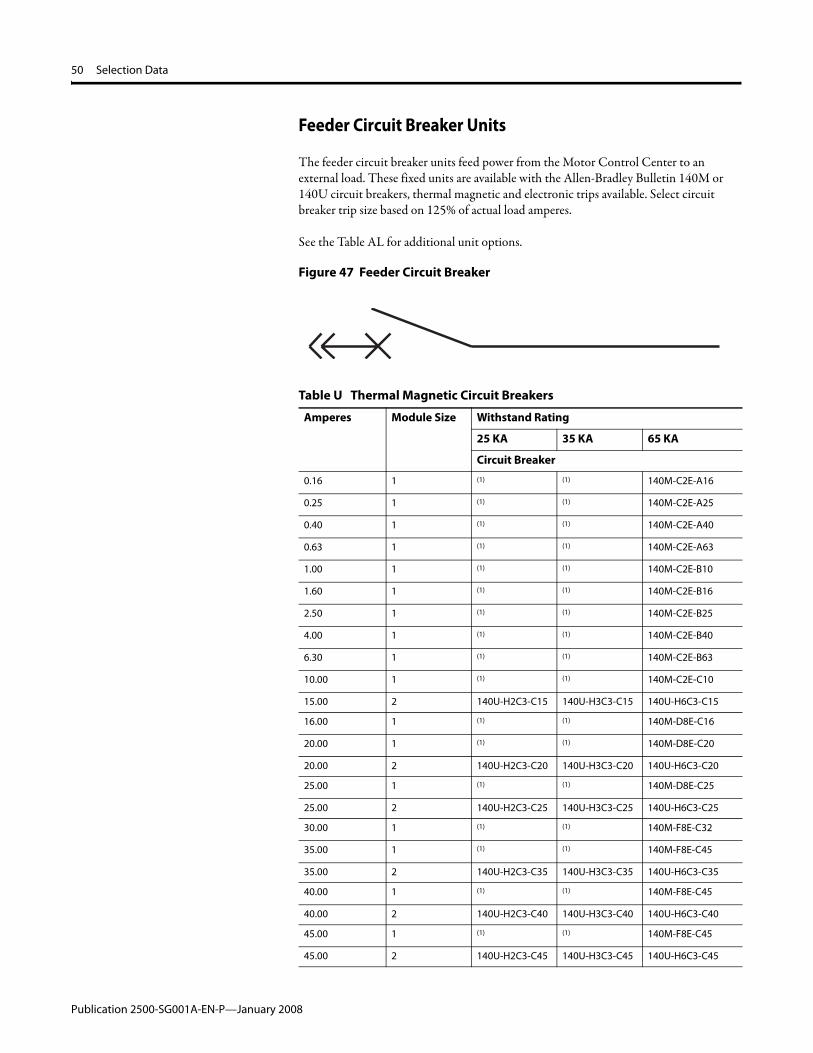
The feeder circuit breaker units feed power from the Motor Control Center to an external load. These fixed units are available with the Allen-Bradley Bulletin 140M or 140U circuit breakers, thermal magnetic and electronic trips available. Select circuit breaker trip size based on 125% of actual load amperes.
See the Table AL for additional unit options.
Figure 47 Feeder Circuit Breaker
Table U Thermal Magnetic Circuit Breakers
Amperes Module Size Withstand Rating
25 KA 35 KA 65 KA
Circuit Breaker
0.16 1 (1) (1) 140M-C2E-A16
0.25 1 (1) (1) 140M-C2E-A25
0.40 1 (1) (1) 140M-C2E-A40
0.63 1 (1) (1) 140M-C2E-A63
1.00 1 (1) (1) 140M-C2E-B10
1.60 1 (1) (1) 140M-C2E-B16
2.50 1 (1) (1) 140M-C2E-B25
4.00 1 (1) (1) 140M-C2E-B40
6.30 1 (1) (1) 140M-C2E-B63
10.00 1 (1) (1) 140M-C2E-C10
15.00 2 140U-H2C3-C15 140U-H3C3-C15 140U-H6C3-C15
16.00 1 (1) (1) 140M-D8E-C16
20.00 1 (1) (1) 140M-D8E-C20
20.00 2 140U-H2C3-C20 140U-H3C3-C20 140U-H6C3-C20
25.00 1 (1) (1) 140M-D8E-C25
25.00 2 140U-H2C3-C25 140U-H3C3-C25 140U-H6C3-C25
30.00 1 (1) (1) 140M-F8E-C32
35.00 1 (1) (1) 140M-F8E-C45
35.00 2 140U-H2C3-C35 140U-H3C3-C35 140U-H6C3-C35
40.00 1 (1) (1) 140M-F8E-C45
40.00 2 140U-H2C3-C40 140U-H3C3-C40 140U-H6C3-C40
45.00 1 (1) (1) 140M-F8E-C45
45.00 2 140U-H2C3-C45 140U-H3C3-C45 140U-H6C3-C45
Publication 2500-SG001A-EN-P—January 2008

Selection Data 51
50.00 2 140U-H2C3-C50 140U-H3C3-C50 140U-H6C3-C50
60.00 2 140U-H2C3-C60 140U-H3C3-C60 140U-H6C3-C60
70.00 2 140U-H2C3-C70 140U-H3C3-C70 140U-H6C3-C70
80.00 2 140U-H2C3-C80 140U-H3C3-C80 140U-H6C3-C80
90.00 2 140U-H2C3-C90 140U-H3C3-C90 140U-H6C3-C90
100.00 2 140U-H2C3-D10 140U-H3C3-D10 140U-H6C3-D10
110.00 2 140U-H2C3-D11 140U-H3C3-D11 140U-H6C3-D11
125.00 2 140U-H2C3-D12 140U-H3C3-D12 140U-H6C3-D12
150.00 2 140U-J2D3-D15 140U-J3D3-D15 140U-J6D3-D15
175.00 2 140U-J2D3-D17 140U-J3D3-D17 140U-J6D3-D17
200.00 2 140U-J2D3-D20 140U-J3D3-D20 140U-J6D3-D20
225.00 2 140U-J2D3-D22 140U-J3D3-D22 140U-J6D3-D22
250.00 2 140U-J2D3-D25 140U-J3D3-D25 140U-J6D3-D25
300.00 8(2) 140U-K3D3-D30 140U-K3D3-D30 140U-K6D3-D30
350.00 8(2) 140U-K3D3-D35 140U-K3D3-D35 140U-K6D3-D35
400.00 8(2) 140U-K3D3-D40 140U-K3D3-D40 140U-K6D3-D40
450.00 8(2) 140U-Q3D3-D45 140U-Q3D3-D45 140U-Q6D3-D45
500.00 8(2) 140U-Q3D3-D50 140U-Q3D3-D50 140U-Q6D3-D50
600.00 8(2) 140U-Q3D3-D60 140U-Q3D3-D60 140U-Q6D3-D60
700.00 10(2) 140U-M5D3-D70 140U-M5D3-D70 140U-M6D3-D70
800.00 10(2) 140U-M5D3-D80 140U-M5D3-D80 140U-M6D3-D80
1200.00 10(2) 140U-N6H3-E12 140U-N6H3-E12 140U-N6H3-E12
(1) Not applicable(2) Fixed mount style
Table U Thermal Magnetic Circuit Breakers
Amperes Module Size Withstand Rating
25 KA 35 KA 65 KA
Circuit Breaker
Publication 2500-SG001A-EN-P—January 2008

52 Selection Data
Main and Feeder Air Circuit Breaker Units
Air circuit breakers (ACB) are available in a withdrawable or fixed unit design. ACBs include an option to use 4-pole breakers.
See Table AL for additional unit options.
See Table AL for additional unit options.
Table V Main Air Circuit Breakers
Amperes Module Size Withstand Rating65 KACircuit Breaker
400 24(1)
(1) Fixed mount style
140RX-N6B3F-D40(2)
(2) Catalog number can be configured to specifications
600 24(1) 140RX-N6B3F-D63(2)
800 24(1) 140RX-N6B3F-D80(2)
1250 24(1) 140RX-N6B3F-E12(2)
1600 24(1) 140RX-N6B3F-E16(2)
2000 24(1) 140RX-R6B3F-E20(2)
2500 24(1) 140RX-R6B3F-E25(2)
3200 24(1) 140RX-S6B3F-E32(2)
4000 24(1) 140RX-S6B3F-E40(2)
Table W Feeder Air Circuit Breakers
Amperes Module Size Withstand Rating 65 KA Circuit Breaker
400 24(1)
(1) Fixed mount style.
140RX-N6B3F-D40(2)
(2) Catalog number can be configured to specifications.
600 24(1) 140RX-N6B3F-D63(2)
800 24(1) 140RX-N6B3F-D80(2)
1250 24(1) 140RX-N6B3F-E12(2)
1600 24(1) 140RX-N6B3F-E16(2)
2000 24(1) 140RX-R6B3F-E20(2)
Publication 2500-SG001A-EN-P—January 2008

Selection Data 53
Direct On Line Starter Units
Direct on line non-reversing and reversing starter units are available with the Allen-Bradley Bulletin 140M or 140U circuit breaker and a eutectic, E1 Plus or E3 Plus overload relay.
SeeTable AM and Table AN for additional unit options.
Figure 48 Direct On Line Reversing
Table X Type 1 or 2 Coordination Direct On Line Reversing Starter Units
Motor kW Rating
Amperes Line Voltage, 380/400 V
Module Size Reversing Contactor
Circuit Breaker Overload Relay
E1 Plus E3 Plus
0.03 0.10 4 104-C37*22(3) 140M-H8P-B30 193-EEAB(4) (5)
0.09 0.20 4 104-C37*22(3) 140M-H8P-B30 193-EEAB(4) (5)
0.12 0.30 4 104-C37*22(3) 140M-H8P-B30 193-EEBB(4) (5)
0.18 0.40 4 104-C37*22(3) 140M-H8P-B30 193-EEBB(4) 193-EC2PB(4)
0.25 0.60 4 104-C37*22(3) 140M-H8P-B30 193-EEBB(4) 193-EC2PB(4)
0.37 1.20 2 104-C37*22(3) 140M-H8P-B30 193-EECD 193-EC2AD
0.55 1.60 2 104-C37*22(3) 140M-H8P-B30 193-EECD 193-EC2AD
0.75 1.80 2 104-C37*22(3) 140M-H8P-B30 193-EECD 193-EC2AD
1.10 2.60 2 104-C37*22(3) 140M-H8P-B70 193-EECD 193-EC2AD
1.50 3.70 2 104-C37*22(3) 140M-H8P-B70 193-EECD 193-EC2AD
2.20 5.30 2 104-C37*22(3) 140M-H8P-C15 193-EEDD 193-EC2BD
3.00 7.00 2 104-C37*22(3) 140M-H8P-C30 193-EEDD 193-EC2BD
3.70 8.20 2 104-C37*22(3) 140M-H8P-C30 193-EEDD 193-EC2BD
4.00 8.50 2 104-C37*22(3) 140M-H8P-C30 193-EEDD 193-EC2BD
4.50 9.60 2 104-C37*22(3) 140M-H8P-C30 193-EEDD 193-EC2BD
5.50 11.50 2 104-C37*22(3) 140M-H8P-C30 193-EEDD 193-EC2BD
7.50 16.00 2 104-C37*22(3) 140M-H8P-C30 193-EEED 193-EC2CD
9.20 19.30 2 104-C37*22(3) 140M-H8P-C30 193-EEED 193-EC2CD
11.00 22.00 2 104-C37*22(3) 140M-H8P-C50 193-EEED 193-EC2CD
15.00 30.00 2 104-C37*22(3) 140M-H8P-C50 193-EEFD 193-EC2DD
18.50 37.00 2 104-C37*22(3) 140M-H8P-C50 193-EEFD 193-EC2DD
22.00 44.00 4 104-C85*22(3) 140M-H8P-D10 193-EEGE 193-EC2EE
Publication 2500-SG001A-EN-P—January 2008

54 Selection Data
30.00 60.00 4 104-C85*22(3) 140M-H8P-D10 193-EEGE 193-EC2EE
37.00 72.00 4 104-C85*22(3) 140M-H8P-D10 193-EEGE 193-EC2EE
45.00 85.00 4 104-C85*22(3) 140M-H8P-D10 193-EEGE 193-EC2EE
55.00 105.00 8(1) 104-D180*24(3) 140M-J8P-D20 193-EEJF 193-EC2GF
55.00 105.00 10 104-D210*24(3) 140M-J8P-D20 193-EEJG 193-EC2GG
75.00 138.00 8(1) 104-D180*24(3) 140M-J8P-D20 193-EEJF 193-EC2GF
75.00 138.00 10 104-D210*24(3) 140M-J8P-D20 193-EEJG 193-EC2GG
90.00 170.00 8 104-D210*24(3) 140M-J8P-D25 193-EEJG 193-EC2GG
110.00 204.00 10(2) 104-D210*24(3) 140M-J8P-D25 193-EEJG 193-EC2HG
132.00 215.00 12(2) 104-D300*24(3) 140M-K8P-D40 193-EELG 193-EC2HG
150.00 245.00 12(2) 104-D300*24(3) 140M-K8P-D40 193-EELG 193-EC2HG
160.00 259.00 12(2) 104-D300*24(3) 140M-K8P-D40 193-EELG 193-EC2HG
185.00 300.00 16(2) 104-D420*24(3) 140M-L8P-D60 193-EELG 193-EC2JG
200.00 324.00 16(2) 104-D420*24(3) 140M-L8P-D60 193-EELG 193-EC2JG
220.00 353.00 16(2) 104-D420*24(3) 140M-L8P-D60 193-EELG 193-EC2JG
(1) Type 1 coordination only(2) Fixed mount style(3) “*” Character depends upon the control voltage(4) Add 193EPB for the E1 Plus or add 193ECPM1 for the E3 Plus(5) Not applicable
Table X Type 1 or 2 Coordination Direct On Line Reversing Starter Units
Motor kW Rating
Amperes Line Voltage, 380/400 V
Module Size Reversing Contactor
Circuit Breaker Overload Relay
E1 Plus E3 Plus
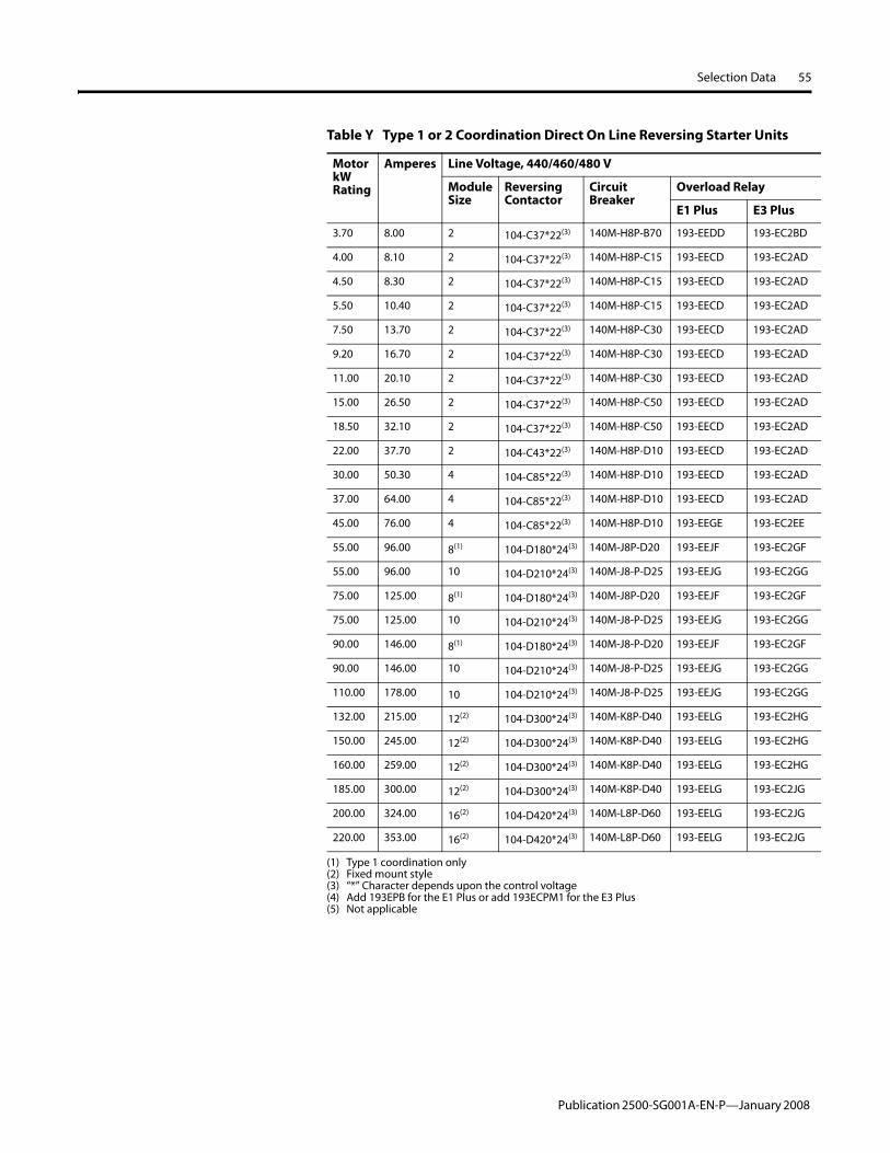
Table Y Type 1 or 2 Coordination Direct On Line Reversing Starter Units
Motor kW Rating
Amperes Line Voltage, 440/460/480 V
Module Size
Reversing Contactor
Circuit Breaker
Overload Relay
E1 Plus E3 Plus
0.03 0.10 2 104-C37*22(3) 140M-H8P-B30 193-EEAB(4) (5)
0.09 0.30 2 104-C37*22(3) 140M-H8P-B30 193-EEBB(4) (5)
0.12 0.30 2 104-C37*22(3) 140M-H8P-B30 193-EEBB(4) (5)
0.18 0.50 2 104-C37*22(3) 140M-H8P-B30 193-EEBB(4) 193-EC2PB(4)
0.25 0.70 2 104-C37*22(3) 140M-H8P-B30 193-EEBB(4) 193-EC2PB(4)
0.37 1.00 2 104-C37*22(3) 140M-H8P-B30 193-EECD 193-EC2AD
0.55 1.40 2 104-C37*22(3) 140M-H8P-B30 193-EECD 193-EC2AD
0.75 1.70 2 104-C37*22(3) 140M-H8P-B30 193-EECD 193-EC2AD
1.10 2.20 2 104-C37*22(3) 140M-H8P-B70 193-EECD 193-EC2AD
1.50 3.10 2 104-C37*22(3) 140M-H8P-B70 193-EECD 193-EC2AD
2.20 4.50 2 104-C37*22(3) 140M-H8P-B70 193-EEDD 193-EC2BD
3.00 5.90 2 104-C37*22(3) 140M-H8P-B70 193-EEDD 193-EC2BD
Publication 2500-SG001A-EN-P—January 2008
Selection Data 55
3.70 8.00 2 104-C37*22(3) 140M-H8P-B70 193-EEDD 193-EC2BD
4.00 8.10 2 104-C37*22(3) 140M-H8P-C15 193-EECD 193-EC2AD
4.50 8.30 2 104-C37*22(3) 140M-H8P-C15 193-EECD 193-EC2AD
5.50 10.40 2 104-C37*22(3) 140M-H8P-C15 193-EECD 193-EC2AD
7.50 13.70 2 104-C37*22(3) 140M-H8P-C30 193-EECD 193-EC2AD
9.20 16.70 2 104-C37*22(3) 140M-H8P-C30 193-EECD 193-EC2AD
11.00 20.10 2 104-C37*22(3) 140M-H8P-C30 193-EECD 193-EC2AD
15.00 26.50 2 104-C37*22(3) 140M-H8P-C50 193-EECD 193-EC2AD
18.50 32.10 2 104-C37*22(3) 140M-H8P-C50 193-EECD 193-EC2AD
22.00 37.70 2 104-C43*22(3) 140M-H8P-D10 193-EECD 193-EC2AD
30.00 50.30 4 104-C85*22(3) 140M-H8P-D10 193-EECD 193-EC2AD
37.00 64.00 4 104-C85*22(3) 140M-H8P-D10 193-EECD 193-EC2AD
45.00 76.00 4 104-C85*22(3) 140M-H8P-D10 193-EEGE 193-EC2EE
55.00 96.00 8(1) 104-D180*24(3) 140M-J8P-D20 193-EEJF 193-EC2GF
55.00 96.00 10 104-D210*24(3) 140M-J8-P-D25 193-EEJG 193-EC2GG
75.00 125.00 8(1) 104-D180*24(3) 140M-J8P-D20 193-EEJF 193-EC2GF
75.00 125.00 10 104-D210*24(3) 140M-J8-P-D25 193-EEJG 193-EC2GG
90.00 146.00 8(1) 104-D180*24(3) 140M-J8-P-D20 193-EEJF 193-EC2GF
90.00 146.00 10 104-D210*24(3) 140M-J8-P-D25 193-EEJG 193-EC2GG
110.00 178.00 10 104-D210*24(3) 140M-J8-P-D25 193-EEJG 193-EC2GG
132.00 215.00 12(2) 104-D300*24(3) 140M-K8P-D40 193-EELG 193-EC2HG
150.00 245.00 12(2) 104-D300*24(3) 140M-K8P-D40 193-EELG 193-EC2HG
160.00 259.00 12(2) 104-D300*24(3) 140M-K8P-D40 193-EELG 193-EC2HG
185.00 300.00 12(2) 104-D300*24(3) 140M-K8P-D40 193-EELG 193-EC2JG
200.00 324.00 16(2) 104-D420*24(3) 140M-L8P-D60 193-EELG 193-EC2JG
220.00 353.00 16(2) 104-D420*24(3) 140M-L8P-D60 193-EELG 193-EC2JG
(1) Type 1 coordination only(2) Fixed mount style(3) “*” Character depends upon the control voltage(4) Add 193EPB for the E1 Plus or add 193ECPM1 for the E3 Plus(5) Not applicable
Table Y Type 1 or 2 Coordination Direct On Line Reversing Starter Units
Motor kW Rating
Amperes Line Voltage, 440/460/480 V
Module Size
Reversing Contactor
Circuit Breaker
Overload Relay
E1 Plus E3 Plus
Publication 2500-SG001A-EN-P—January 2008

56 Selection Data
Figure 49 Direct On Line Non-Reversing
Table Z Type 1 or 2 Coordination Direct On Line Non-Reversing Starter Units
Motor kW Rating
Amperes Line Voltage, 380/400 V
Module Size Non-Reversing Contactor
Circuit Breaker Overload Relay
E1 Plus E3 Plus
0.03 0.10 2(1) 100-C37*10(4) 140M-H8P-B30 193-EEAB(5) (6)
0.09 0.20 2(1) 100-C37*10(4) 140M-H8P-B30 193-EEAB(5) (6)
0.12 0.30 2(1) 100-C37*10(4) 140M-H8P-B30 193-EEBB(5) (6)
0.18 0.40 2(1) 100-C37*10(4) 140M-H8P-B30 193-EEBB(5) 193-EC2PB(5)
0.25 0.60 2(1) 100-C37*10(4) 140M-H8P-B30 193-EEBB(5) 193-EC2PB(5)
0.37 1.20 2(1) 100-C37*10(4) 140M-H8P-B30 193-EECD 193-EC2AD
0.55 1.60 2(1) 100-C37*10(4) 140M-H8P-B30 193-EECD 193-EC2AD
0.75 1.80 2(1) 100-C37*10(4) 140M-H8P-B30 193-EECD 193-EC2AD
1.10 2.60 2(1) 100-C37*10(4) 140M-H8P-B30 193-EECD 193-EC2AD
1.50 3.70 2(1) 100-C37*10(4) 140M-H8P-B70 193-EECD 193-EC2AD
2.20 5.30 2(1) 100-C37*10(4) 140M-H8P-B70 193-EEDD 193-EC2BD
3.00 7.00 2(1) 100-C37*10(4) 140M-H8P-C15 193-EEDD 193-EC2BD
3.70 8.20 2(1) 100-C37*10(4) 140M-H8P-C15 193-EEDD 193-EC2BD
4.00 8.50 2(1) 100-C37*10(4) 140M-H8P-C15 193-EEDD 193-EC2BD
4.50 9.60 2(1) 100-C37*10(4) 140M-H8P-C15 193-EEDD 193-EC2BD
5.50 11.50 2(1) 100-C37*10(4) 140M-H8P-C30 193-EEDD 193-EC2BD
7.50 16.00 2 100-C37*10(4) 140M-H8P-C30 193-EEBD 193-EC2CD
9.20 19.30 2 100-C37*10(4) 140M-H8P-C30 193-EECD 193-EC2CD
11.00 22.00 2 100-C37*10(4) 140M-H8P-C50 193-EECD 193-EC2CD
15.00 30.00 2 100-C37*10(4) 140M-H8P-C50 193-EEFD 193-EC2DD
18.50 37.00 2 100-C37*10(4) 140M-H8P-C50 193-EEFD 193-EC2DD
22.00 44.00 4 100-C85*10(4) 140M-H8P-D10 193-EEGE 193-EC2EE
30.00 60.00 4 100-C85*10(4) 140M-H8P-D10 193-EEGE 193-EC2EE
37.00 72.00 4 100-C85*10(4) 140M-H8P-D10 193-EEGE 193-EC2EE
45.00 85.00 4 100-C85*10(4) 140M-H8P-D10 193-EEGE 193-EC2EE
55.00 105.00 8(2) 100-D180*11(4) 140M-J8P-D20 193-EEJF 193-EC2GF
55.00 105.00 10 100-D210*11(4) 140M-J8P-D20 193-EEJG 193-EC2GG
75.00 138.00 8(2) 100-D180*11(4) 140M-J8P-D20 193-EEJF 193-EC2GF
75.00 138.00 10 100-D210*11(4) 140M-J8P-D25 193-EEJG 193-EC2GG
90.00 170.00 8 100-D210*11(4) 140M-J8P-D25 193-EEJG 193-EC2GG/GF
Publication 2500-SG001A-EN-P—January 2008

Selection Data 57
110.00 204.00 10 100-D210*11(4) 140M-J8P-D25 193-EEJG 193-EC2HG
132.00 215.00 12(3) 100-D300*11(4) 140M-K8P-D40 193-EELG 193-EC2HG
150.00 245.00 12(3) 100-D300*11(4) 140M-K8P-D40 193-EELG 193-EC2HG
160.00 259.00 12(3) 100-D300*11(4) 140M-K8P-D40 193-EELG 193-EC2HG
185.00 300.00 16(3) 100-D420*11(4) 140M-L8P-D60 193-EELG 193-EC2JG
200.00 324.00 16(3) 100-D420*11(4) 140M-L8P-D60 193-EELG 193-EC2JG
220.00 353.00 16(3) 100-D420*11(4) 140M-L8P-D60 193-EELG 193-EC2JG
(1) Module size may increase for E1 Plus overload relays(2) Type 1 coordination only(3) Fixed mount style(4) “*” Character depends upon the control voltage(5) Add 193EPB for the E1 Plus or add 193ECPM1 for the E3 Plus(6) Not applicable
Table Z Type 1 or 2 Coordination Direct On Line Non-Reversing Starter Units
Motor kW Rating
Amperes Line Voltage, 380/400 V
Module Size Non-Reversing Contactor
Circuit Breaker Overload Relay
E1 Plus E3 Plus
Table AA Type 1 or 2 Coordination Direct On Line Non-Reversing Starter Units
Motor kW Rating
Amperes Line Voltage, 440/460/480 V
Module Size Non-Reversing Contactor
Circuit Breaker Overload Relay
E1 Plus E3 Plus
0.03 0.10 2(1) 100-C37*10(4) 140M-H8P-B30 193-EEAB(5) (6)
0.09 0.30 2(1) 100-C37*10(4) 140M-H8P-B30 193-EEBB(5) (6)
0.12 0.30 2(1) 100-C37*10(4) 140M-H8P-B30 193-EEBB(5) (6)
0.18 0.50 2(1) 100-C37*10(4) 140M-H8P-B30 193-EEBB(5) 193-EC2PB(5)
0.25 0.70 2(1) 100-C37*10(4) 140M-H8P-B30 193-EEBB(5) 193-EC2PB(5)
0.37 1.00 2(1) 100-C37*10(4) 140M-H8P-B30 193-EECD 193-EC2AB
0.55 1.40 2(1) 100-C37*10(4) 140M-H8P-B30 193-EECD 193-EC2AB
0.75 1.70 2(1) 100-C37*10(4) 140M-H8P-B70 193-EECD 193-EC2AB
1.10 2.20 2(1) 100-C37*10(4) 140M-H8P-B70 193-EECD 193-EC2AB
1.50 3.10 2(1) 100-C37*10(4) 140M-H8P-B70 193-EECD 193-EC2AB
2.20 4.50 2(1) 100-C37*10(4) 140M-H8P-B70 193-EEDD 193-EC2BB
3.00 5.90 2(1) 100-C37*10(4) 140M-H8P-C15 193-EEDD 193-EC2BB
3.70 8.10 2(1) 100-C37*10(4) 140M-H8P-C15 193-EEDD 193-EC2BB
4.00 8.08 2(1) 100-C37*10(4) 140M-H8P-C15 193-EEDD 193-EC2BB
4.50 8.30 2(1) 100-C37*10(4) 140M-H8P-C15 193-EEDD 193-EC2BB
5.50 10.40 2(1) 100-C37*10(4) 140M-H8P-C30 193-EEDD 193-EC2BB
7.50 13.70 2 100-C37*10(4) 140M-H8P-C30 193-EEED 193-EC2CB
9.20 16.70 2 100-C37*10(4) 140M-H8P-C30 193-EEED 193-EC2CB
11.00 20.10 2 100-C37*10(4) 140M-H8P-C30 193-EEED 193-EC2CB
Publication 2500-SG001A-EN-P—January 2008

58 Selection Data
15.00 26.50 2 100-C37*10(4) 140M-F8N-C50 193-EEFD 193-EC2DD
18.50 32.10 2 100-C37*10(4) 140M-F8N-C50 193-EEFD 193-EC2DD
22.00 37.70 2 100-C43*10(1) 140M-H8P-D10 193-EEFD 193-EC2DD
30.00 50.30 4 100-C85*10(1) 140M-H8P-D10 193-EEGE 193-EC2EE
37.00 64.00 4 100-C85*10(1) 140M-H8P-D10 193-EEGE 193-EC2EE
45.00 76.00 4 100-C85*10(1) 140M-H8P-D10 193-EEGE 193-EC2EE
55.00 96.00 8(2) 100-D180*11(4) 140M-J8P-D20 193-EEJF 193-EC2GF
55.00 96.00 10 100-D210*11(4) 140M-J8-P-D25 193-EEJG 193-EC2GG
75.00 125.00 8(2) 100-D180*11(4) 140M-J8P-D20 193-EEJF 193-EC2GF
75.00 125.00 10 100-D210*11(4) 140M-J8-P-D25 193-EEJG 193-EC2GG
90.00 146.00 8(2) 100-D180*11(4) 140M-J8-P-D20 193-EEJF 193-EC2GF
90.00 146.00 10 100-D210*11(4) 140M-J8-P-D25 193-EEJG 193-EC2GG
110.00 178.00 10 100-D210*11(4) 140M-J8-P-D25 193-EEJG/JF 193-EC2GG
132.00 215.00 12(3) 100-D300*11(4) 140M-K8P-D40 193-EELG 193-EC2HG
150.00 245.00 12(3) 100-D300*11(4) 140M-K8P-D40 193-EELG 193-EC2HG
160.00 259.00 12(3) 100-D300*11(4) 140M-K8P-D40 193-EELG 193-EC2HG
185.00 300.00 12(3) 100-D300*11(4) 140M-K8P-D40 193-EELG 193-EC2JG
200.00 324.00 16(3) 100-D420*11(4) 140M-L8P-D60 193-EELG 193-EC2JG
220.00 353.00 16(3) 100-D420*11(4) 140M-L8P-D60 193-EELG 193-EC2JG
(1) Module size may increase for E1 Plus overload relays(2) Type 1 coordination only(3) Fixed mount style(4) “*” Character depends upon the control voltage(5) Add 193EPB for the E1 Plus or add 193ECPM1 for the E3 Plus(6) Not applicable
Table AA Type 1 or 2 Coordination Direct On Line Non-Reversing Starter Units
Motor kW Rating
Amperes Line Voltage, 440/460/480 V
Module Size Non-Reversing Contactor
Circuit Breaker Overload Relay
E1 Plus E3 Plus
Publication 2500-SG001A-EN-P—January 2008

Selection Data 59
Reduced Voltage Solid State (Soft Starter) Units
Reduced voltage solid state units are available with an Allen-Bradley Bulletin 140M or 140U circuit breaker and an Allen-Bradley Bulletin 150 SMC.
See the Table AO for additional unit options.
Figure 50 Reduced Voltage Solid State
Table AB Reduced Voltage Solid State (Soft Starter) Units
Motor kW Rating
Unit Ampere Rating
Line Voltage, 380/400 V
Module Size SMC-3 Circuit Breaker
Fuse Size, Fuse Body Size(1)
(1) Ferraz Shawmut NH DIN Type Am fuses supplied
IP 20 IP42/IP54
0.37 1.20 6 6 150-C3NBD 140M-H8P-B30 2A, Size 000
0.55 1.60 6 6 150-C3NBD 140M-H8P-B30 4A, Size 000
0.75 1.76 6 6 150-C3NBD 140M-H8P-B30 4A, Size 000
1.10 2.60 6 6 150-C3NBD 140M-H8P-B70 4A, Size 000
1.50 3.70 6 6 150-C9NBD 140M-H8P-B70 6A, Size 000
2.20 5.30 6 6 150-C9NBD 140M-H8P-C15 6A, Size 000
3.00 7.00 6 6 150-C9NBD 140M-H8P-C15 10A, Size 000
3.70 8.20 6 6 150-C9NBD 140M-H8P-C15 16A, Size 000
4.00 8.50 6 6 150-C9NBD 140M-H8P-C15 16A, Size 000
4.50 9.60 6 6 150-C19NBD 140M-H8P-C15 20A, Size 000
5.50 11.50 6 6 150-C19NBD 140M-H8P-C30 20A, Size 000
7.50 16.00 6 6 150-C19NBD 140M-H8P-C30 20A, Size 000
9.20 19.30 6 6 150-C25NBD 140M-H8P-C30 25A, Size 000
11.00 22.00 6 6 150-C25NBD 140M-H8P-C50 40A, Size 000
15.00 30.00 6 6 150-C30NBD 140M-H8P-C50 40A, Size 000
18.50 37.00 6 6 150-C37NBD 140M-H8P-C50 50A, Size 000
22.00 44.00 6 6 150-C43NBD 140M-H8P-D10 63A, Size 000
30.00 60.00 6 6 150-C60NBD 140M-H8P-D10 80A, Size 00
37.00 72.00 6 6 150-C85NBD 140M-H8P-D10 100A, Size 00
45.00 85.00 6 6 150-C85NBD 140M-H8P-D10 125A, Size 00
55.00 105.00 12 12 150-C108NBD 140M-J8P-D20 125A, Size 00
75.00 138.00 12 12 150-C135NBD 140M-J8P-D20 200A, Size 1
Publication 2500-SG001A-EN-P—January 2008

60 Selection Data
Table AC Reduced Voltage Solid State (Soft Starter) Units
Motor kW Rating
Unit Ampere Rating
Line Voltage, 440/460/480 V
Module Size SMC-3 Circuit Breaker
Fuse Size, Fuse Body Size(1)
(1) Ferraz Shawmut NH DIN Type Am fuses supplied
IP 20 IP42/IP54
0.37 1.00 6 6 150-C3NBD 140M-C2N-B16 2A, Size 000
0.55 1.40 6 6 150-C3NBD 140M-C2N-B25 4A, Size 000
0.75 1.70 6 6 150-C3NBD 140M-C2N-B25 4A, Size 000
1.10 2.20 6 6 150-C3NBD 140M-D8N-B40 4A, Size 000
1.50 3.10 6 6 150-C9NBD 140M-D8N-B40 6A, Size 000
2.20 4.50 6 6 150-C9NBD 140M-D8N-B63 6A, Size 000
3.00 5.90 6 6 150-C9NBD 140M-D8N-C10 10A, Size 000
3.70 8.00 6 6 150-C9NBD 140M-D8N-C10 16A, Size 000
4.00 8.10 6 6 150-C9NBD 140M-D8N-C10 16A, Size 000
4.50 8.30 6 6 150-C19NBD 140M-D8N-C10 20A, Size 000
5.50 10.40 6 6 150-C19NBD 140M-D8N-C16 20A, Size 000
7.50 13.70 6 6 150-C19NBD 140M-D8N-C16 20A, Size 000
9.20 16.70 6 6 150-C25NBD 140M-D8N-C25 25A, Size 000
11.00 20.10 6 6 150-C25NBD 140M-D8N-C25 40A, Size 000
15.00 26.50 6 6 150-C30NBD 140M-F8N-C32 40A, Size 000
18.50 32.10 6 6 150-C37NBD 140M-F8N-C45 50A, Size 000
22.00 37.70 6 6 150-C43NBD 140M-H8P-D10 63A, Size 000
30.00 50.30 6 6 150-C60NBD 140M-H8P-D10 80A, Size 00
37.00 64.00 6 6 150-C85NBD 140M-H8P-D10 100A, Size 00
45.00 76.00 6 6 150-C85NBD 140M-H8P-D10 125A, Size 00
55.00 96.00 12 12 150-C108NBD 140M-J8P-D20 125A, Size 00
75.00 125.00 12 12 150-C135NBD 140M-J8P-D20 200A, Size 1
Publication 2500-SG001A-EN-P—January 2008

Selection Data 61
Table AD Reduced Voltage Solid State (Soft Starter) Units
Motor kW Rating
Unit Ampere Rating
Line Voltage, 380/400 V
Module Size SMC-Flex Circuit Breaker
Fuse Size, Fuse Body Size(2)
(2) Ferraz Shawmut NH DIN Type Am fuses supplied
IP 20 IP42/IP54
0.37 1.00 8 10 150-F5NBD 140M-H8P-B30 2A, Size 000
0.55 1.60 8 10 150-F5NBD 140M-H8P-B30 4A, Size 000
0.75 1.76 8 10 150-F5NBD 140M-H8P-B30 4A, Size 000
1.10 2.20 8 10 150-F5NBD 140M-H8P-B70 4A, Size 000
1.50 3.70 8 10 150-F5NBD 140M-H8P-B70 6A, Size 000
2.20 5.30 8 10 150-F5NBD 140M-H8P-B70 6A, Size 000
3.00 7.00 8 10 150-F25NBD 140M-H8P-C15 10A, Size 000
3.70 8.20 8 10 150-F25NBD 140M-H8P-C15 16A, Size 000
4.00 8.10 8 10 150-F25NBD 140M-H8P-C15 16A, Size 000
4.50 9.60 8 10 150-F25NBD 140M-H8P-C15 20A, Size 000
5.50 11.50 8 10 150-F25NBD 140M-H8P-C15 20A, Size 000
7.50 16.00 8 10 150-F25NBD 140M-H8P-C30 20A, Size 000
9.20 19.30 8 10 150-F25NBD 140M-H8P-C30 25A, Size 000
11.00 22.00 8 10 150-F25NBD 140M-H8P-C30 40A, Size 000
15.00 30.00 8 10 150-F43NBD 140M-H8P-C50 40A, Size 000
18.50 37.00 8 10 150-F43NBD 140M-H8P-C50 50A, Size 000
22.00 44.00 8 10 150-F43NBD 140M-H8P-D10 63A, Size 000
30.00 60.00 8 10 150-F60NBD 140M-H8P-D10 80A, Size 00
37.00 72.00 8 10 150-F85NBD 140M-H8P-D10 100A, Size 00
45.00 85.00 8 10 150-F85NBD 140M-H8P-D10 125A, Size 00
55.00 105.00 12 14(1) 150-F108NBD 140M-J8P-D20 125A, Size 00
75.00 138.00 12 14(1) 150-F201NBD 140M-J8P-D20 200A, Size 1
90.00 170.00 24(1)
(1) Fixed mount style
24(1) 150-F201NBD 140M-J8P-D25 250A, Size 1
110.00 204.00 24(1) 24(1) 150-F251NBD 140M-J8P-D25 355A, Size 2
132.00 215.00 24(1) 24(1) 150-F251NBD 140M-K8P-D40 355A, Size 2
150.00 245.00 24(1) 24(1) 150-F317NBD 140M-K8P-D40 400A, Size 2
160.00 259.00 24(1) 24(1) 150-F317NBD 140M-K8P-D40 500A, Size 3
185.00 300.00 24(1) 24(1) 150-F361NBD 140M-L8P-D60 500A, Size 3
200.00 324.00 24(1) 24(1) 150-F480NBD 140M-L8P-D60 630A, Size 3
220.00 353.00 24(1) 24(1) 150-F480NBD 140M-L8P-D60 630A, Size 3
Publication 2500-SG001A-EN-P—January 2008
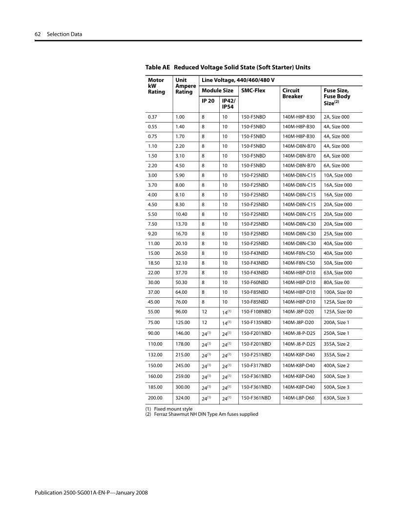
62 Selection Data
Table AE Reduced Voltage Solid State (Soft Starter) Units
Motor kW Rating
Unit Ampere Rating
Line Voltage, 440/460/480 V
Module Size SMC-Flex Circuit Breaker
Fuse Size, Fuse Body Size(2)
(2) Ferraz Shawmut NH DIN Type Am fuses supplied
IP 20 IP42/IP54
0.37 1.00 8 10 150-F5NBD 140M-H8P-B30 2A, Size 000
0.55 1.40 8 10 150-F5NBD 140M-H8P-B30 4A, Size 000
0.75 1.70 8 10 150-F5NBD 140M-H8P-B30 4A, Size 000
1.10 2.20 8 10 150-F5NBD 140M-D8N-B70 4A, Size 000
1.50 3.10 8 10 150-F5NBD 140M-D8N-B70 6A, Size 000
2.20 4.50 8 10 150-F5NBD 140M-D8N-B70 6A, Size 000
3.00 5.90 8 10 150-F25NBD 140M-D8N-C15 10A, Size 000
3.70 8.00 8 10 150-F25NBD 140M-D8N-C15 16A, Size 000
4.00 8.10 8 10 150-F25NBD 140M-D8N-C15 16A, Size 000
4.50 8.30 8 10 150-F25NBD 140M-D8N-C15 20A, Size 000
5.50 10.40 8 10 150-F25NBD 140M-D8N-C15 20A, Size 000
7.50 13.70 8 10 150-F25NBD 140M-D8N-C30 20A, Size 000
9.20 16.70 8 10 150-F25NBD 140M-D8N-C30 25A, Size 000
11.00 20.10 8 10 150-F25NBD 140M-D8N-C30 40A, Size 000
15.00 26.50 8 10 150-F43NBD 140M-F8N-C50 40A, Size 000
18.50 32.10 8 10 150-F43NBD 140M-F8N-C50 50A, Size 000
22.00 37.70 8 10 150-F43NBD 140M-H8P-D10 63A, Size 000
30.00 50.30 8 10 150-F60NBD 140M-H8P-D10 80A, Size 00
37.00 64.00 8 10 150-F85NBD 140M-H8P-D10 100A, Size 00
45.00 76.00 8 10 150-F85NBD 140M-H8P-D10 125A, Size 00
55.00 96.00 12 14(1) 150-F108NBD 140M-J8P-D20 125A, Size 00
75.00 125.00 12 14(1) 150-F135NBD 140M-J8P-D20 200A, Size 1
90.00 146.00 24(1)
(1) Fixed mount style
24(1) 150-F201NBD 140M-J8-P-D25 250A, Size 1
110.00 178.00 24(1) 24(1) 150-F201NBD 140M-J8-P-D25 355A, Size 2
132.00 215.00 24(1) 24(1) 150-F251NBD 140M-K8P-D40 355A, Size 2
150.00 245.00 24(1) 24(1) 150-F317NBD 140M-K8P-D40 400A, Size 2
160.00 259.00 24(1) 24(1) 150-F361NBD 140M-K8P-D40 500A, Size 3
185.00 300.00 24(1) 24(1) 150-F361NBD 140M-K8P-D40 500A, Size 3
200.00 324.00 24(1) 24(1) 150-F361NBD 140M-L8P-D60 630A, Size 3
Publication 2500-SG001A-EN-P—January 2008

Selection Data 63
Variable Frequency Drive Units
Variable frequency drive units are available with an Allen-Bradley Bulletin 140M or 140U circuit breaker and an Allen-Bradley PowerFlex drive.
See Table AP for additional unit options.
Figure 51 Variable Frequency Drive, PowerFlex 40
Table AF PowerFlex 40 Drive Units
Motor kW Rating
Unit Ampere Rating
Line Voltage, 380/400 V
Module Size PowerFlex 40 Circuit Breaker Reactor(1)
No Reactor Reactor
IP 20 IP42/IP54
IP 20 IP 42/IP54
0.37 1.20 4 6 6 6 22B-D1P4N104 140M-H8P-B30 1321-3R2-B
0.55 1.60 4 6 6 6 22B-D2P3N104 140M-H8P-B30 1321-3R4-C
0.75 1.80 4 6 6 6 22B-D2P3N104 140M-H8P-B30 1321-3R4-C
1.10 1.60 4 6 6 6 22B-D4P0N104 140M-H8P-B70 1321-3R4-B
1.50 3.70 4 6 6 6 22B-D4P0N104 140M-H8P-B70 1321-3R4-B
2.20 5.30 4 6 6 6 22B-D6P0N104 140M-H8P-C15 1321-3R8-C
3.00 7.00 6 6 8 8 22B-D010N104 140M-H8P-C15 1321-3R8-B
3.70 8.20 6 6 8 8 22B-D010N104 140M-H8P-C15 1321-3R12-B
4.00 8.50 8 10 8 10 22B-D012N104 140M-H8P-C15 1321-3R12-B
4.50 9.60 8 10 8 10 22B-D012N104 140M-H8P-C15 1321-3R12-B
5.50 11.50 8 10 8 10 22B-D012N104 140M-H8P-C30 1321-3R12-B
7.50 16.00 8 10 8 10 22B-D017N104 140M-H8P-C30 1321-3R18-B
9.20 19.30 8 10 8 10 22B-D024N104 140M-H8P-C30 1321-3R25-B
11.00 22.00 8 10 8 10 22B-D024N104 140M-H8P-C50 1321-3R25-B
(1) Line or load reactors are optional, consult factory for details
Publication 2500-SG001A-EN-P—January 2008

64 Selection Data
Table AG PowerFlex 40 Drive Units
Motor kW Rating
Unit Ampere Rating
Line Voltage, 440/460/480 V
Module Size PowerFlex 40 Circuit Breaker Reactor(1)
No Reactor Reactor
IP 20 IP42/IP54
IP 20 IP 42/IP54
0.37 1.00 4 6 6 6 22B-D1P4N104 140M-H8P-B30 1321-3R2-B
0.55 1.40 4 6 6 6 22B-D2P3N104 140M-H8P-B30 1321-3R4-C
0.75 1.70 4 6 6 6 22B-D2P3N104 140M-H8P-B30 1321-3R4-C
1.10 2.20 4 6 6 6 22B-D4P0N104 140M-H8P-B70 1321-3R4-B
1.50 3.10 4 6 6 6 22B-D4P0N104 140M-H8P-B70 1321-3R4-B
2.20 4.50 4 6 6 6 22B-D6P0N104 140M-H8P-B70 1321-3R8-C
3.00 5.90 6 6 8 8 22B-D010N104 140M-H8P-C15 1321-3R8-B
3.70 8.00 6 6 8 8 22B-D010N104 140M-H8P-C15 1321-3R12-B
4.00 8.08 8 10 8 10 22B-D012N104 140M-H8P-C15 1321-3R12-B
4.50 8.30 8 10 8 10 22B-D012N104 140M-H8P-C15 1321-3R12-B
5.50 10.40 8 10 8 10 22B-D012N104 140M-H8P-C15 1321-3R12-B
7.50 13.70 8 10 8 10 22B-D017N104 140M-H8P-C30 1321-3R18-B
9.20 16.70 8 10 8 10 22B-D024N104 140M-H8P-C30 1321-3R25-B
11.00 20.10 8 10 8 10 22B-D024N104 140M-H8P-C30 1321-3R25-B
(1) Line or load reactors are optional, consult factory for details
Publication 2500-SG001A-EN-P—January 2008

Selection Data 65
Figure 52 Variable Frequency Drive, PowerFlex 70
Table AH PowerFlex 70 Drive Units
Motor kW Rating
Unit Ampere Rating
Line Voltage, 380/400 V
Module Size PowerFlex 70(2) Circuit Breaker Reactor(3)
No Reactor Reactor
IP 20 IP42/IP54
IP 20 IP 42/54
0.37 1.2 6 8 8 10 20AC1P3A0AYNANC0 140M-H8P-B30 1321-3R2-B
0.55 1.6 6 8 8 10 20AC2P1A0AYNANC0 140M-H8P-B30 1321-3R2-B
0.75 1.8 6 8 8 10 20AC2P1A0AYNANC0 140M-H8P-B30 1321-3R2-B
1.10 2.6 6 8 8 10 20AC3P5A0AYNANC0 140M-D8N-B70 1321-3R4-B
1.50 3.7 6 8 8 10 20AC3P5A0AYNANC0 140M-D8N-B70 1321-3R4-B
2.20 5.3 6 8 8 10 20AC5P0A0AYNANC0 140M-D8N-C15 1321-3R8-C
3.00 7.0 6 8 8 10 20AC8P7A0AYNANC0 140M-D8N-C15 1321-3R8-B
3.70 8.2 6 8 8 10 20AC8P7A0AYNANC0 140M-D8N-C15 1321-3R8-B
4.00 8.5 8 12 10 12 20AD011A0AYNANC0 140M-D8N-C15 1321-3R12-B
4.50 9.6 8 12 10 12 20AD011A0AYNANC0 140M-D8N-C15 1321-3R12-B
5.50 11.5 8 12 10 12 20AD011A0AYNANC0 140M-D8N-C30 1321-3R12-B
7.50 16.0 8 12 10 12 20AC015A0AYNANC0 140M-D8N-C30 1321-3R18-B
9.20 19.3 10 12 10 12 20AC022A0AYNANC0 140M-D8N-C30 1321-3R25-B
11.00 22 10 12 10 12 20AC022A0AYNANC0 140M-D8N-C50 1321-3R25-B
15.00 30 10 14(1) 10 14(1) 20AC030A0AYNANC0 140M-D8N-C50 1321-3R35-B
18.50 37 10 14(1) 10 14(1) 20AC037A0AYNANC0 140M-D8N-C50 1321-3R45-B
22.00 44 12 14(1) 14(1) 14(1) 20AC043A0AYNANC0 140M-H8P-D10 1321-3R55-B
30.00 60 14(1) 16(1) 16(1) 16(1) 20AC060A0AYNANC0 140M-H8P-D10 1321-3R80-B
37.00 72 14(1) 16(1) 16(1) 16(1) 20AC072A0AYNANC0 140M-H8P-D10 1321-3R80-B
(1) Fixed mount style(2) For 120VAC control add AK-M9-115VAC-1(3) Line or load reactors are optional, consult factory for details
Publication 2500-SG001A-EN-P—January 2008

66 Selection Data
Table AI PowerFlex 70 Drive Units
Motor kW Rating
Unit Ampere Rating
Line Voltage, 440/460/480 V
Module Size PowerFlex 70(2) Circuit Breaker Reactor(3)
No Reactor Reactor
IP 20 IP42/IP54
IP 20 IP 42/IP 54
0.37 1.0 6 8 8 10 20AD1P1A0AYNNNC0 140M-H8P-B30 1321-3R2-B
0.55 1.4 6 8 8 10 20AD2P1A0AYNNNC0 140M-H8P-B30 1321-3R2-B
0.75 1.7 6 8 8 10 20AD2P1A0AYNNNC0 140M-H8P-B30 1321-3R2-B
1.10 2.2 6 8 8 10 20AD3P4A0AYNNNC0 140M-D8N-B70 1321-3R4-B
1.50 3.1 6 8 8 10 20AD3P4A0AYNNNC0 140M-D8N-B70 1321-3R4-B
2.20 4.5 6 8 8 10 20AD5P0A0AYNNNC0 140M-D8N-B70 1321-3R8-C
3.00 5.9 6 8 8 10 20AD8P0A0AYNNNC0 140M-D8N-C15 1321-3R8-B
3.70 8.0 6 8 8 10 20AD8P0A0AYNNNC0 140M-D8N-C15 1321-3R8-B
4.00 8.1 8 12 10 12 20AD011A0AYNANC0 140M-D8N-C15 1321-3R12-B
4.50 8.3 8 12 10 12 20AD011A0AYNANC0 140M-D8N-C15 1321-3R12-B
5.50 10.4 8 12 10 12 20AD011A0AYNANC0 140M-D8N-C15 1321-3R12-B
7.50 13.7 8 12 10 12 20AD014A0AYNANC0 140M-D8N-C30 1321-3R18-B
9.20 16.7 10 12 10 12 20AD022A0AYNANC0 140M-D8N-C30 1321-3R25-B
11.00 20.1 10 12 10 12 20AD022A0AYNANC0 140M-D8N-C30 1321-3R25-B
15.00 26.5 10 14(1) 10 14(1) 20AD027A0AYNANC0 140M-D8N-C50 1321-3R35-B
18.50 32.1 10 14(1) 10 14(1) 20AD034A0AYNANC0 140M-D8N-C50 1321-3R45-B
22.00 37.7 12 14(1) 14(1) 14(1) 20AD040A0AYNANC0 140M-H8P-D10 1321-3R55-B
30.00 50.3 14(1) 16(1) 16(1) 16(1) 20AD052A0AYNANC0 140M-H8P-D10 1321-3R80-B
37.00 64 14(1) 16(1) 16(1) 16(1) 20AD065A0AYNANC0 140M-H8P-D10 1321-3R80-B
(1) Fixed mount style(2) For 120VAC control add AK-M9-115VAC-1(3) Line or load reactors are optional, consult factory for details
Publication 2500-SG001A-EN-P—January 2008

Selection Data 67
Figure 53 Variable Frequency Drive, PowerFlex 700
Table AJ PowerFlex 700 Drive Units
Motor kW Rating
Unit Ampere Rating
Line Voltage, 380/400 V
Module Size PowerFlex 700 Circuit Breaker Reactor(6)
No Reactor Reactor
IP 20 IP42/IP54
IP 20 IP 42/IP 54
0.37 1.2 8 8 8 10 20BC1P3A0AYNAN*0(5) 140M-C2N-B16 1321-3R2-B
0.55 1.6 8 8 8 10 20BC2P1A0AYNAN*0(5) 140M-C2N-B25 1321-3R2-B
0.75 1.8 8 8 8 10 20BC2P1A0AYNAN*0(5) 140M-C2N-B25 1321-3R2-B
1.10 2.6 8 8 8 10 20BC3P5A0AYNAN*0(5) 140M-D8N-B40 1321-3R4-B
1.50 3.7 8 8 8 10 20BC3P5A0AYNAN*0(5) 140M-D8N-B40 1321-3R4-B
2.20 5.3 8 8 8 10 20BC5P0A0AYNAN*0(5) 140M-D8N-B63 1321-3R8-C
3.00 7.0 8 8 8 10 20BC8P7A0AYNAN*0(5) 140M-D8N-C10 1321-3R8-B
3.70 8.2 8 8 8 10 20BC8P7A0AYNAN*0(5) 140M-D8N-C10 1321-3R8-B
4.00 8.5 8 8 8 10 20BC011A0AYNAN*0(5) 140M-D8N-C10 1321-3R12-B
4.50 9.6 8 8 8 10 20BC011A0AYNAN*0(5) 140M-D8N-C10 1321-3R12-B
5.50 11.5 8 8 8 10 20BC011A0AYNAN*0(5) 140M-D8N-C16 1321-3R12-B
7.50 16.0 8 8 8 10 20BC015A0AYNAN*0(5) 140M-D8N-C16 1321-3R18-B
9.20 19.3 8 12 8 14(1) 20BC022A0AYNAN*0(5) 140M-D8N-C25 1321-3R25-B
11.00 22 8 12 8 14(1) 20BC022A0AYNAN*0(5) 140M-D8N-C25 1321-3R25-B
15.00 30 8 12 10 14(1) 20BC030A0AYNAN*0(5) 140M-F8N-C45 1321-3R35-B
18.50 37 8 12 10 14(1) 20BC037A0AYNAN*0(5) 140M-F8N-C45 1321-3R45-B
22.00 44 12 12 14(1) 14(1) 20BC043A0AYNAN*0(5) 140M-H8P-D10 1321-3R55-B
30.00 60 12 14(1) 14(1) 16(1) 20BC056A0AYNAN*0(5) 140M-H8P-D10 1321-3R80-B
37.00 72 12 14(1) 14(1) 16(1) 20BC072A0AYNAN*0(5) 140M-H8P-D10 1321-3R80-B
45.00 85 24(1), (2) 24(1), (2) 24(1), (2) 24(1), (2) 20BC105A0ANNAN*0(5) 140M-H8P-D10 1321-3R100-B
55.00 105 24(1), (2) 24(1), (2) 24(1), (2) 24(1), (2) 20BC105A0ANNAN*0(5) 140M-J8P-D20 1321-3R130-B
75.00 138 24(1), (2) 24(1), (2) 24(1), (2) 24(1), (2) 20BC170A0ANNAN*0(5) 140M-J8P-D20 1321-3R160-B
90.00 170 24(1), (2) 24(1), (3) 24(1), (2) 24(1), (3) 20BC170A0ANNAN*0(5) 140M-J8P-D25 1321-3R200-B
110.00 204 24(1), (3) (4) 24(1), (3) (4) 20CD300A0ANNBNN0(5) 140M-J8P-D25 1321-3RB250-B
132 215 24(1), (3) (4) 24(1), (3) (4) 20CD300A0ANNBNN0(5) 140M-K8P-D40 1321-3RB250-B
(1) Fixed mount style(2) 700 mm width required(3) 800 mm width required(4) Not applicable(5) “*” Character depends upon the control voltage(6) Line or load reactors are optional, consult factory for details
Publication 2500-SG001A-EN-P—January 2008
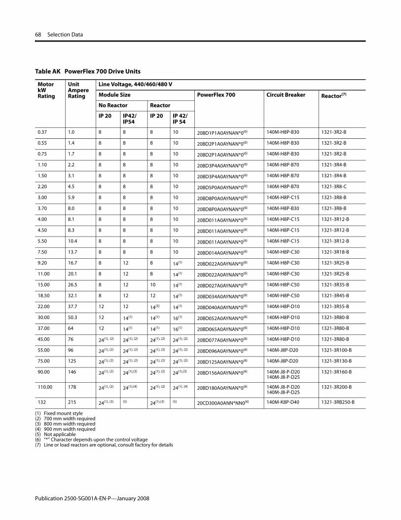
68 Selection Data
Table AK PowerFlex 700 Drive Units
Motor kW Rating
Unit Ampere Rating
Line Voltage, 440/460/480 V
Module Size PowerFlex 700 Circuit Breaker Reactor(7)
No Reactor Reactor
IP 20 IP42/IP54
IP 20 IP 42/IP 54
0.37 1.0 8 8 8 10 20BD1P1A0AYNAN*0(6) 140M-H8P-B30 1321-3R2-B
0.55 1.4 8 8 8 10 20BD2P1A0AYNAN*0(6) 140M-H8P-B30 1321-3R2-B
0.75 1.7 8 8 8 10 20BD2P1A0AYNAN*0(6) 140M-H8P-B30 1321-3R2-B
1.10 2.2 8 8 8 10 20BD3P4A0AYNAN*0(6) 140M-H8P-B70 1321-3R4-B
1.50 3.1 8 8 8 10 20BD3P4A0AYNAN*0(6) 140M-H8P-B70 1321-3R4-B
2.20 4.5 8 8 8 10 20BD5P0A0AYNAN*0(6) 140M-H8P-B70 1321-3R8-C
3.00 5.9 8 8 8 10 20BD8P0A0AYNAN*0(6) 140M-H8P-C15 1321-3R8-B
3.70 8.0 8 8 8 10 20BD8P0A0AYNAN*0(6) 140M-H8P-B30 1321-3R8-B
4.00 8.1 8 8 8 10 20BD011A0AYNAN*0(6) 140M-H8P-C15 1321-3R12-B
4.50 8.3 8 8 8 10 20BD011A0AYNAN*0(6) 140M-H8P-C15 1321-3R12-B
5.50 10.4 8 8 8 10 20BD011A0AYNAN*0(6) 140M-H8P-C15 1321-3R12-B
7.50 13.7 8 8 8 10 20BD014A0AYNAN*0(6) 140M-H8P-C30 1321-3R18-B
9.20 16.7 8 12 8 14(1) 20BD022A0AYNAN*0(6) 140M-H8P-C30 1321-3R25-B
11.00 20.1 8 12 8 14(1) 20BD022A0AYNAN*0(6) 140M-H8P-C30 1321-3R25-B
15.00 26.5 8 12 10 14(1) 20BD027A0AYNAN*0(6) 140M-H8P-C50 1321-3R35-B
18.50 32.1 8 12 12 14(1) 20BD034A0AYNAN*0(6) 140M-H8P-C50 1321-3R45-B
22.00 37.7 12 12 14[3] 14(1) 20BD040A0AYNAN*0(6) 140M-H8P-D10 1321-3R55-B
30.00 50.3 12 14(1) 14(1) 16(1) 20BD052A0AYNAN*0(6) 140M-H8P-D10 1321-3R80-B
37.00 64 12 14(1) 14(1) 16(1) 20BD065A0AYNAN*0(6) 140M-H8P-D10 1321-3R80-B
45.00 76 24(1), (2) 24(1), (2) 24(1), (2) 24(1), (2) 20BD077A0AYNAN*0(6) 140M-H8P-D10 1321-3R80-B
55.00 96 24(1), (2) 24(1), (2) 24(1), (2) 24(1), (2) 20BD096A0AYNAN*0(6) 140M-J8P-D20 1321-3R100-B
75.00 125 24(1), (2) 24(1), (2) 24(1), (2) 24(1), (2) 20BD125A0AYNAN*0(6) 140M-J8P-D20 1321-3R130-B
90.00 146 24(1), (2) 24(1),(3) 24(1), (2) 24(1),(3) 20BD156A0AYNAN*0(6) 140M-J8-P-D20140M-J8-P-D25
1321-3R160-B
110.00 178 24(1), (2) 24(1),(4) 24(1), (2) 24(1), (4) 20BD180A0AYNAN*0(6) 140M-J8-P-D20140M-J8-P-D25
1321-3R200-B
132 215 24(1), (3) (5) 24(1),(3) (5) 20CD300A0ANN*NN0(6) 140M-K8P-D40 1321-3RB250-B
(1) Fixed mount style(2) 700 mm width required(3) 800 mm width required(4) 900 mm width required(5) Not applicable(6) “*” Character depends upon the control voltage(7) Line or load reactors are optional, consult factory for details
Publication 2500-SG001A-EN-P—January 2008

Selection Data 69
Unit Options
Table AL Main and Feeder Unit Options
Option Description
Auxiliary contact for circuit breaker or disconnect switch - 1 NO, 1 NC
Auxiliary contact for circuit breaker or disconnect switch - 2 NO, 2 NC
Shunt trip coil for circuit breaker
Alarm contact for circuit breaker
Minimum voltage coil (undervoltage) for circuit breaker
Combination auxiliary contact and alarm contact for circuit breaker
Table AM Direct On Line Non-Reversing Starter Unit Options
Option Description
Auxiliary contact for contactors - 1 NO, 1 NC
Auxiliary contact for contactors - 2 NO, 2 NC
Auxiliary contact for contactors - 3 NO, 1 NC
Auxiliary contact for contactors - 1 NO, 3 NC
Auxiliary contact for contactors - 4 NO
Auxiliary contact for contactors - 4 NC
Auxiliary contact for circuit breaker or disconnect switch - 1 NO, 1 NC
Auxiliary contact for circuit breaker or disconnect switch - 2 NO, 2 NC
Surge suppressor
Pilot lights, incandescent
Pilot lights, LED
Pilot Lights, Incandescent, Push-to-Test
Pilot Lights, LED, Push-to-Test
Push buttons
Two position selector switch
Three position selector switch
Control circuit transformer
DeviceNet starter auxiliary, (4) 120VAC inputs and (2) 120VAC outputs for DeviceNet
DeviceNet starter auxiliary, (4) 24VDC inputs and (2) 120VAC outputs for DeviceNet
Arc containment latches
Control wire markers
Shunt trip coil for circuit breaker
Alarm contact for circuit breaker
Minimum voltage coil (undervoltage) for circuit breaker
Combination auxiliary contact and alarm contact for circuit breaker
Publication 2500-SG001A-EN-P—January 2008

70 Selection Data
Table AN Direct On Line Reversing Starter Unit Options
Option Description
Auxiliary contact for contactors - 1 NO, 1 NC
Auxiliary contact for contactors - 2 NO, 2 NC
Auxiliary contact for contactors - 3 NO, 1 NC
Auxiliary contact for contactors - 1 NO, 3 NC
Auxiliary contact for contactors - 4 NO
Auxiliary contact for contactors - 4 NC
Auxiliary contact for circuit breaker or disconnect switch - 1 NO, 1 NC
Auxiliary contact for circuit breaker or disconnect switch - 2 NO, 2 NC
Surge suppressor
Pilot lights, incandescent
Pilot lights, LED
Pilot Lights, Incandescent, Push-to-Test
Pilot Lights, LED, Push-to-Test
Push buttons
Two position selector switch
Three position selector switch
Control circuit transformer
DeviceNet starter auxiliary, (4) 120VAC inputs and (2) 120VAC outputs for DeviceNet
DeviceNet starter auxiliary, (4) 24VDC inputs and (2) 120VAC outputs for DeviceNet
Arc containment latches
Control wire markers
Shunt trip coil for circuit breaker
Alarm contact for circuit breaker
Minimum voltage coil (undervoltage) for circuit breaker
Combination auxiliary contact and alarm contact for circuit breaker
Table AO Reduced Voltage Solid State Unit Options
Option Description
Auxiliary contact for contactors - 1 NO, 1 NC
Auxiliary contact for contactors - 2 NO, 2 NC
Auxiliary contact for contactors - 3 NO, 1 NC
Auxiliary contact for contactors - 1 NO, 3 NC
Auxiliary contact for contactors - 4 NO
Auxiliary contact for contactors - 4 NC
Auxiliary contact for circuit breaker or disconnect switch - 1 NO, 1 NC
Auxiliary contact for circuit breaker or disconnect switch - 2 NO, 2 NC
Surge suppressor
Pilot lights, incandescent
Pilot lights, LED
Publication 2500-SG001A-EN-P—January 2008

Selection Data 71
Pilot Lights, Incandescent, Push-to-Test
Pilot Lights, LED, Push-to-Test
Push buttons
Two position selector switch
Three position selector switch
Control circuit transformer
DeviceNet starter auxiliary, (4) 120VAC inputs and (2) 120VAC outputs for DeviceNet
DeviceNet starter auxiliary, (4) 24VDC inputs and (2) 120VAC outputs for DeviceNet
Arc containment latches
Control wire markers
Shunt trip coil for circuit breaker
Alarm contact for circuit breaker
Minimum voltage coil (undervoltage) for circuit breaker
Combination auxiliary contact and alarm contact for circuit breaker
Table AP Variable Frequency Drive Unit Options
Option Description
Auxiliary contact for circuit breaker or disconnect switch - 1 open, 1 closed
Auxiliary contact for circuit breaker or disconnect switch - 2 open, 2 closed
Surge suppressor
Pilot lights, incandescent
Pilot lights, LED
Pilot Lights, Incandescent, Push-to-Test
Pilot Lights, LED, Push-to-Test
Push buttons
Two position selector switch
Three position selector switch
Control circuit transformer
DeviceNet starter auxiliary, (4) 120VAC inputs and (2) 120VAC outputs for DeviceNet
DeviceNet starter auxiliary, (4) 24VDC inputs and (2) 120VAC outputs for DeviceNet
DeviceNet communication module, mounted internal to drive
ControlNet communication module, mounted internal to drive
Human interface module, blank cover, no functionality, door mounted in bezel
Human interface module, LCD display, full numeric keypad, door mounted in bezel
Human interface module, LCD display, programmer only, door mounted in bezel
I/O control interface type, 24 VDC control voltage interface with vector control
I/O control interface type, 120 VAC control voltage interface with vector control
I/O control interface type, 24 VDC control voltage interface with sensorless vector control
I/O control interface type, 120 VAC control voltage interface with sensorless vector control
Table AO Reduced Voltage Solid State Unit Options
Option Description
Publication 2500-SG001A-EN-P—January 2008
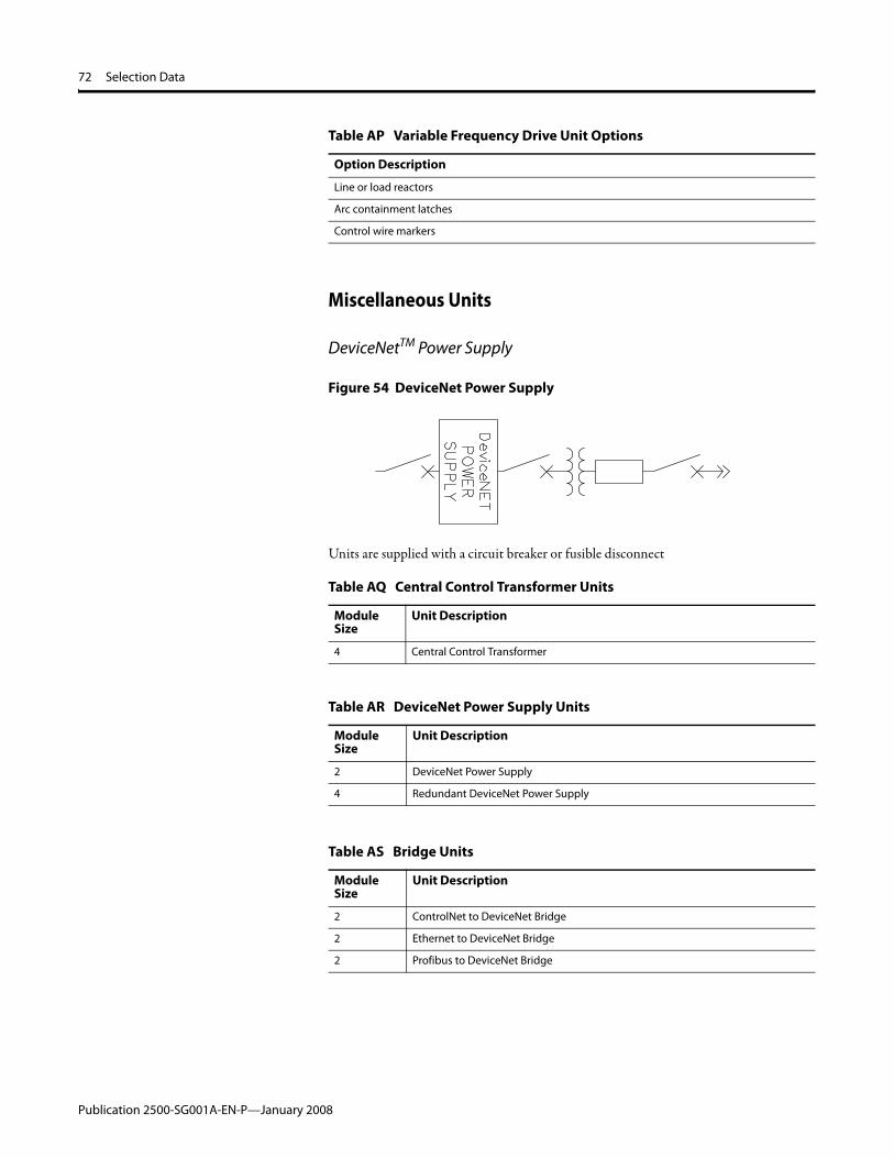
72 Selection Data
Miscellaneous Units
DeviceNetTM Power Supply
Figure 54 DeviceNet Power Supply
Units are supplied with a circuit breaker or fusible disconnect
Line or load reactors
Arc containment latches
Control wire markers
Table AQ Central Control Transformer Units
Module Size
Unit Description
4 Central Control Transformer
Table AR DeviceNet Power Supply Units
Module Size
Unit Description
2 DeviceNet Power Supply
4 Redundant DeviceNet Power Supply
Table AS Bridge Units
Module Size
Unit Description
2 ControlNet to DeviceNet Bridge
2 Ethernet to DeviceNet Bridge
2 Profibus to DeviceNet Bridge
Table AP Variable Frequency Drive Unit Options
Option Description
Publication 2500-SG001A-EN-P—January 2008

Selection Data 73
Table AT Empty Units
Module Size
Unit Description
2 Empty Unit Insert
4 Empty Unit Insert
6 Empty Unit Insert
8 Empty Unit Insert
10 Empty Unit Insert
12 Empty Unit Insert
Table AU Blank Mounting Plate Units
Module Size
Unit Description
2 Blank Mounting Plate
4 Blank Mounting Plate
6 Blank Mounting Plate
8 Blank Mounting Plate
10 Blank Mounting Plate
12 Blank Mounting Plate
Publication 2500-SG001A-EN-P—January 2008

74 Selection Data
Technical Data Table AV CENTERLINE 2500 Specifications
StandardsEN 60439-1:1999 + A1:2004 Low-voltage switchgear and controlgear assemblies
Part 1: Type-tested and partially type-tested assemblies
EN 60204-1:1997 Safety of machinery – Electrical equipment of machinesPart 1: General requirements
EC Directives2006/95/EC Low Voltage Directive as amended by 93/68/EEC89/336/EEC EMC Directive as amended by 92/31/EEC and 93/68/EEC
2002/95/EC(1) Restriction of the Use of Certain Hazardous Substances in Electrical and Electronic Equipment (RoHS)
Certifications and MarkingsChina Compulsory Certificate (CCC)CE Conformance MarkedKEMA certified (TTA)
Rated VoltagesRated Operating Voltage, Ue Up to 690 V, 3-Phase
Rated Frequency, fn 50 – 60 Hz
Rated Insulation Voltage, Ui 1000 V, 3-Phase
Rated Currents Horizontal Bus Vertical BusContinuous Current Rating, Ie Up to 4000 A Up to 600 A
Short Circuit Peak Withstand, Ipk Up to 176 kA for 1 second Up to 110 kA for 3 second
Short Time Withstand Rating, Icw Up to 80 kA for 1 second Up to 50 kA for 1 second
Neutral (N) Full or half ratedCreepage Distances and Clearances
Rated Impulse Withstand Voltage, Uimp 6, 8, or 12 kV
Material Group (Overvoltage Category) IIIa (175 </= CTI < 400)Pollution Degree 3
Bus Material and PlatingHorizontal Power Bus Copper (optional tin plating)Vertical Distribution Bus Copper with tin platingProtective Earth Conductor (PE) Copper (optional tin plating)
Degrees of ProtectionIEC 60529 IP 20, 30, 42 or 54
Forms of SeparationIEC 60439-1 Form 3b or 4b
Column DimensionsHeight 2300 mmWidth 700, 800, 900 or 1000 mmDepth 600 or 800 mm (1200 mm, double-front)
UnitsApproximate Module Size 80 mm high x 500 mm wide = 1 moduleModules per Column 24Withdrawable Unit Sizes 1, 2, 4, 6, 8, 10, 12 modules
Structural Surface TreatmentsInterior High Visibility White Paint (Additional colors available by request.)Exterior RAL 7032 Pebble Grey Paint or Munsell 6.5 Paint (Additional colors available by request.)
EnvironmentStorage Temperature -25°C to +55°COperating (Ambient) Temperature -5°C to +40°CAltitude Up to 1000 m
(1) Low voltage Motor Control Center products are exempt under Category 9, however Rockwell Automation is committed to demonstrating the highest standard of global environmental management. It is the goal of Rockwell Automation to meet the material restrictions on products, even where compliance is not legally required.
Publication 2500-SG001A-EN-P—January 2008


Publication 2500-SG001A-EN-P—January 200876 Copyright © 2008 Rockwell Automation, Inc. Printed in the U.S.A.
Supersedes Publication 2100-TD001A-EN-P—September 2006