centerline 2500 motor control centers specification guide
TRANSCRIPT

CENTERLINE® 2500
Motor Control Centers
Specification Guide


Publication 2500-TD001A-EN-P—September 2006
1
General Information The CENTERLINE® 2500 motor control center (MCC) consists of one or more columns bolted together forming a rigid, free-standing assembly designed to allow the addition of future columns. See Figure 1.
Figure 1 CENTERLINE 2500 Motor Control Center
The MCC is designed with full isolation of electrical components from the front side of the enclosure. When doors are latched and covers are secured, a person on the operating side of the equipment is not exposed to live parts.
Units installed in MCC columns are populated with a full line of IEC components, contactors, overload relays, AC drives, soft starters and other devices.
Technical Standards and Certifications
The MCC is designed and tested to meet or exceed the requirements defined by the following IEC standards and directives.
• EN 60439-1:1999 + A1:2004, the standard for type-tested and partially type-tested assemblies of low voltage switchgear and control gear assemblies (TTA, PTA)
• EN 60204-1:1997, the general requirements for the safety of electrical equipment of machines
• 73/23/EEC, the low voltage directive as amended by 93/68/EEC• 89/336/EEC, the EMC directive as amended by 92/31/EEC and
93/68/EEC• 2002/95/EC, the restriction of hazardous substances directive (RoHS)
The MCC columns, units and components are available with the CE Conformance Mark.
The MCC is designed, manufactured and tested in facilities registered to ISO 9001 quality standards.

Publication 2500-TD001A-EN-P—September 2006
2
Operating Environment
The MCC is intended for use in a pollution degree 3 environment.
The MCC is designed to operate in the following ambient conditions. The ambient operating temperature shall range from -5°C to +40°C, with the average temperature in any 24 hour period not exceeding +35°C.
The MCC is designed to operate at altitudes up to 1000 m. For altitudes exceeding 1000 m, contact your Rockwell Automation representative for derating information.
Form of Separation
Internal isolation and separation exists between the following.
• Individual units• Units and wireways• Units and the bus system• Wireways and the bus system
In addition, the vertical wireway for line and load connections is separate from the vertical wireway for control and network connections.
Standard internal separation within the MCC is Form 3b. Form 4b is available by enclosing terminals for external conductors in a metal box within the vertical wireway. See Figure 2.
Figure 2 Internal Separation
Form 3b Form 4b

Publication 2500-TD001A-EN-P—September 2006
3
Mounting Configurations
The MCC is available in two mounting configurations – front-only and double-front. See Figure 3.
• Front-only columns are joined and installed side-by-side. • Double-front columns are comprised of two separate columns joined
at the rear. Back plates are not present between the columns. The two columns have separate power bus systems providing the same phasing on units, both front and rear. Full usage of unit space is available for front and rear columns. The horizontal power bus is linked, front to rear, with a factory installed U-shaped bus splice assembly.
Figure 3 Mounting Configurations
Packaging and Shipping Blocks
The MCC must remain in the upright position at all times (e.g., during transportation, storage and installation).
Standard packaging consists of columns bolted to a wooden skid with removable shipping angles and covered with a clear, plastic wrap. Heavy duty/export packaging is also available. Heavy duty/export packaging is similar to standard packaging, but the MCC is completely surrounded by wood framing and sheeting. Standard packaging and heavy duty/export packaging is not waterproof or watertight and is not intended for long-term storage.
Columns packaged for transport are considered shipping blocks. Columns are generally shipped individually, but in some instances maybe joined together for ease of transportation. Shipping blocks contain continuous horizontal power bus, lifting angles, support angles and mounting channels and cannot be separated at the installation site.
Front-Only
Double-Front

Publication 2500-TD001A-EN-P—September 2006
4
Two 700 mm wide columns may be joined side-by-side and transported as a single shipping block. Up to four 700 mm columns or two 800 - 1000 mm columns in double-front configuration may be transported as a single shipping block. A single column could also be considered a shipping block. See Figure 4.
Figure 4 One Column Shipping Block
Shipping Angle(4 places)

Publication 2500-TD001A-EN-P—September 2006
5
Structure Columns
Columns are rigid, free-standing structures with heavy duty external mounting channels continuous for the width of the shipping block. Columns are secured at the installation site by bolting through clearance holes in the mounting channels or welding.
A removable continuous steel lifting angle is provided on all shipping blocks. Two lifting angles are provided for double-front columns. See Figure 5.
Figure 5 Column Construction
Removable Top Plate
Top Horizontal Wireway Pan
Top Horizontal Wireway Barrier
Top Horizontal Wireway Cover
Vertical Wireway Door
Bottom Horizontal Wireway Cover
Right Unit Support and Vertical Wireway Assembly
Bottom Plates
Mounting Channels
Center End Closing Plate
Bottom Horizontal Wireway Closing Plates
Top Horizontal Wireway Closing Plates
Horizontal Power Bus
Left Side Plate
Control and Network Wireway
Lifting Angle

Publication 2500-TD001A-EN-P—September 2006
6
Column Dimensions
Standard column width is 700 mm. Each column is 2300 mm high and 600 mm deep. See Figure 6. Double-front columns are also available. See Tables A, B and C for additional options.
Unit size is described in terms of modules. Each module is approximately 80 mm high x 500 mm wide. Columns can accommodate 24 modules of varying unit combinations.
Horizontal wireways extend the full depth of the column. Vertical wireways are approximately 350 mm deep. Table A Column Width
Total Column Width Unit Width Vertical Wireway Width700 mm (standard) 500 mm 200 mm
800 mm 500 mm 300 mm
900 mm 500 mm 400 mm
1000 mm 500 mm 500 mm
Table B Column Depth
Front Only Double-Front600 mm 1200 mm
800 mm 1600 mm
Table C Column Height
Feature HeightTotal Height 2300 mm
Available Unit Height 1980 mm
Top Horizontal Wireway 170 mm
Bottom Horizontal Wireway 115 mm
External Mounting Channel 35 mm

Publication 2500-TD001A-EN-P—September 2006
7
Figure 6 Typical Column Dimensions (mm)
Structure Material
Table D lists the approximate thickness and gauge of the MCC structural components and external covers.
Table D CENTERLINE 2500 Structure Details
Structural Components Thickness (mm) Approximate Gauge (AWG)
Side Plate 2.0 14
Back Plate 2.5 12
Covers and Panels
Top Plate 2.0 14
Bottom Plate 2.0 14
End Closing Plate 2.0 14
Horizontal Wireway Cover 2.0 14
Doors
Unit Door 2.0 14
170
1980
115
2300
700-1000
600
500 200-500
35

Publication 2500-TD001A-EN-P—September 2006
8
Approximate Weight
Table E lists approximate weights for typical MCC columns. Note that many factors (e.g. number of units, horizontal power bus rating, wireway width, column depth) affect the weight of a column. Weight is added when the product is packaged for shipping.
Vertical Wireway Door 2.0 14
Other Steel
External Mounting Channel 3.5 10
Table E Approximate Column Weight
Column Width Approximate Weight (1)
(1) Weights are for a typical motor control center with 6 units per column. Weights do not include packaging. Refer to the packing slip shipped with your MCC for exact shipping weights.
700 mm 350 kg
800 mm 400 kg
900 mm 450 kg
1000 mm 500 kg
Table D CENTERLINE 2500 Structure Details

Publication 2500-TD001A-EN-P—September 2006
9
Enclosure
Degree of Protection
In accordance with IEC 60529, enclosures are available with the following IP ratings.
• IP 20 (vented doors)• IP 30 (vented doors with filters)• IP 41 (non-vented doors, standard)• IP 54 (gasketed with bottom plates, future option)
Enclosure metal work has rounded edges and is tightly fitted with no visible air gaps. Gasketing is made of closed cell neoprene material.
Paint and Plating
Structural metal parts undergo a multi-step cleaning, rinsing and painting process resulting in complete paint coverage of uniform thickness. The process is maintained and controlled by ISO 9001 quality standards.
Standard exterior paint color is RAL 7032 Pebble Grey. Other colors, including Munsell 6.5, are available by request.
Closing plates, channel supports, lifting angles and horizontal wireway covers are painted RAL 7021 Black Grey.
Interior vertical wireways and unit mounting plates are painted high visibility gloss white. Other colors are available by request.
Zinc with trivalent chromate is used to plate unpainted surfaces for corrosion resistance.

Publication 2500-TD001A-EN-P—September 2006
10
Wireways
Horizontal Wireways
Horizontal wireways are located at the top and bottom of each MCC column. Horizontal wireways extend the full width and depth of the MCC. A barrier is present in the top horizontal wireway to provide a connection point for DeviceNet™ receptacles. The top horizontal wireway is 170 mm high, while the bottom horizontal wireway is 115 mm high. Complete access from front to rear is available for MCC columns configured with double-front construction.
Horizontal wireways have removable front covers that are held in place by captive screws. Openings are provided in each side plate of the column in the top and bottom horizontal wireways to allow access between joined columns. Closing plates are provided for these openings for columns located at the end of a MCC lineup. See Figure 7.
Horizontal wireways are isolated from the power bus. Horizontal wireways for incoming line sections have a reduced depth to maintain isolation from the incoming line area.
Figure 7 Top Horizontal Wireway (Covers Removed)
Vertical Wireway
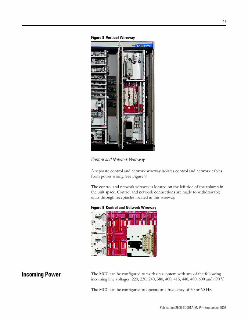
The vertical wireway is located on the right side of each column and extends 1980 mm, from top to bottom horizontal wireway. The vertical wireway is approximately 350 mm deep. The standard vertical wireway is 200 mm wide. Vertical wireways are also available in widths of 300, 400 and 500 mm. Wider wireways are recommended for MCCs with higher bus ratings. See Figure 8.
The vertical wireway is isolated from power bus and is independent of unit space. Vertical wireways are not present in columns with fixed (frame-mounted) units.
Vertical wireways are covered with steel doors, held in place by four door latches. See Door Latches on page 30.
Optional cable supports for use in vertical wireways are available.
Publication 2500-TD001A-EN-P—September 2006
11
Figure 8 Vertical Wireway
Control and Network Wireway
A separate control and network wireway isolates control and network cables from power wiring. See Figure 9.
The control and network wireway is located on the left side of the column in the unit space. Control and network connections are made to withdrawable units through receptacles located in this wireway.
Figure 9 Control and Network Wireway
Incoming Power The MCC can be configured to work on a system with any of the following incoming line voltages: 220, 230, 240, 380, 400, 415, 440, 480, 600 and 690 V.
The MCC can be configured to operate at a frequency of 50 or 60 Hz.

Publication 2500-TD001A-EN-P—September 2006
12
Three-phase, three-wire system power is standard. Optional three-phase, four-wire systems will be available as a future option.
Power Bus The MCC features the time-proven Allen-Bradley CENTERLINE power bus system. The horizontal power bus is mounted near the vertical center of the structure providing optimum heat dissipation, power distribution and ease of maintenance and installation. It is mounted in recessed channels of the bus support to protect against accumulation of dust and tracking between phases. Figure 10 shows a CENTERLINE power bus with neutral.
The vertical power bus allows power distribution both above and below the center-mounted horizontal bus, effectively doubling the capacity in each column. This feature also helps allow a virtually unrestricted unit arrangement.
Horizontal and vertical power bus is fastened together with a two bolt assembly. This two-bolt connection helps minimize the likelihood of “hot spots.” The factory-made horizontal to vertical power bus connection is tightened by a computerized torquing system.
The power bus system is supported, braced and isolated by a bus support molded of high strength, non-tracking glass polyester material. The horizontal power bus is mounted on-edge in a vertical plane providing maximum strength against magnetic forces. Vertical power busbars are continuously braced and sandwiched by a polycarbonate molded bus cover isolating the vertical power bus from the other vertical phases and the horizontal power bus.
Bus bracing is available with the following rms symmetrical current ratings.
• 50 kA for 3 cycles at 60 Hz (standard)• 65 kA for 3 cycles at 60 Hz• 50 kA for 1 s• 50 kA for 3 s (horizontal power bus only)• 80 kA for 1 s (horizontal power bus only)

Publication 2500-TD001A-EN-P—September 2006
13
Figure 10 CENTERLINE Power Bus with Neutral (Covers Removed)
Horizontal Power Bus
Standard horizontal power bus material is unplated copper. Tin-plated copper horizontal power bus is available as an option.
Vertical spacing between the horizontal power busbars is 165 mm.

Publication 2500-TD001A-EN-P—September 2006
14
See Table F for available horizontal power bus ratings and sizes.
The CENTERLINE horizontal power bus is continuous in each column or shipping block.
Splicing horizontal power bus is accomplished using a splice kit of the same ampere rating as the horizontal power bus. Double stud clamp assemblies comprised of flat washers and pre-assembled nuts and conical washers are used. These assemblies provide a minimum of four M10 x 1.5 bolted connections on each side of the splice as shown in Figure 11. The splice connections are front accessible through the vertical wireway for servicing. Because the horizontal power bus is mounted near the vertical center of the column, a ladder is not required for servicing the power bus or bus splice connections.
Figure 11 Horizontal Power Bus Splice
Vertical Power Bus
The vertical power bus material is tin-plated copper.
Vertical power busbars are cylindrical providing optimum contact with the unit plug-in stabs.
Table F Horizontal Power Bus Ratings and Descriptions
Power Bus Rating Busbar Quantity and Dimensions
800 A (standard) 1 - 3 x 100 mm
1200 A 1 - 6 x 100 mm
1600 A 2 - 6 x 100 mm
2000 A 1 - 6 x 100 mm and 1 - 10 x 100 mm
2500 A 2 - 10 x 100 mm
3200 A(1)
(1) Future option
2 - 10 x 100 mm with 10 mm spacers
4000 A(1) 3 - 10 x 100 mm with 10 mm spacers

Publication 2500-TD001A-EN-P—September 2006
15
The standard vertical power bus is a copper tube rated 300 A above and below the horizontal power bus for an effective 600 A rating. An optional copper rod rated 600 A above and below the horizontal power bus for an effective 1200 A rating is available.
Horizontal spacing between the vertical power busbars is 100 mm.
Neutral Bus
The horizontal neutral bus, when specified for four-wire systems, is provided across the full width of the MCC and located above or below the horizontal power bus. Figure 12 shows a neutral bus located above the horizontal power bus.
The neutral bus matches the material and specifications of the vertical power bus.
The horizontal neutral bus is available with a full or half rating.
The vertical neutral bus is mechanically joined to the horizontal neutral bus and provides a neutral contact for plug-in unit stabs throughout the length of the column.
Spacing between the horizontal power busbars and horizontal neutral busbar is 165 mm. Spacing between the vertical power busbar and vertical neutral busbar is 75 mm.
The neutral bus is braced the same way as the horizontal and vertical power bus.
Four-wire systems with a neutral bus will be available as a future option.

Publication 2500-TD001A-EN-P—September 2006
16
Figure 12 Neutral Bus Located Above the Horizontal Power Bus (Back View)
Automatic Shutters
Automatic shutters are standard on CENTERLINE 2500 MCCs. Automatic shutters open as withdrawable units are inserted and close when the unit is removed. This safety feature helps ensure that the vertical bus is immediately isolated when a withdrawable unit is removed. See Figure 13.
Figure 13 Automatic Shutters

Publication 2500-TD001A-EN-P—September 2006
17
Protective Earth Conductor Horizontal Protective Earth Conductor
The horizontal protective earth conductor (PE) is made from unplated copper, or optional tin-plated copper, and is located in the bottom horizontal wireway. See Figure 14. The horizontal PE is continuous for the width of the column and is comprised of one, two or three 6 x 50 mm conductors. The horizontal PE contains 12 evenly spaced 8 mm holes along the length of the conductor for making equipment connections.
A pressure type mechanical lug is mounted on the horizontal PE conductor in the incoming line section.
Figure 14 Horizontal PE
Vertical Plug-In Protective Earth Conductor
A 6 x 32 mm unplated copper vertical plug-in PE conductor is provided in each standard column. An optional tin-plated copper vertical plug-in PE conductor is also available. The vertical plug-in PE conductor is mechanically connected to the horizontal PE conductor forming a complete internal protective earth circuit.
The vertical plug-in PE conductor in combination with the unit PE contact establishes a first make, last break operation of the PE connection with respect to power connections.

Publication 2500-TD001A-EN-P—September 2006
18
Main Incoming Compartment
Main Incoming Line (Lug-Only) Compartment
Main incoming line lug compartments are available in either top or bottom entry and utilize mechanical screw or crimp/compression lugs. Compartments are front accessible.
Refer to Table G for more information on available incoming line compartment arrangements and sizes.
Main Incoming Circuit Breaker
Main incoming circuit breakers are available as air circuit breakers (ACB) or molded case circuit breakers (MCCB).
Main ACB units are available in a withdrawable or fixed design and must be located at top or bottom of a column. See Figure 15.
ACBs for mains include an option to utilize 4-pole breakers. ACBs may be integrated into auto-transfer switch schemes.
MCCBs are inverse time circuit breakers and can be classified as thermal magnetic or electronic.
Main circuit breaker units are front accessible and have removable protective barriers on the line side to help reduce the possibility of accidental contact with line terminals.
Table G Main Incoming Line Compartments
Incoming Line Compartment Rating
6 modules (480 mm), variable column width 600 A (using vertical power bus)
24 modules (full column), 700 mm wide 800, 1200, 1600, 2000 A
24 modules (full column), 800 mm wide 2500, 3200(1), 4000(1) A(1) Future option

Publication 2500-TD001A-EN-P—September 2006
19
Figure 15 Air Circuit Breaker
Main Incoming Fusible Disconnect
Mains with fusible disconnects will be available as a future option.

Publication 2500-TD001A-EN-P—September 2006
20
Units Unit Types
Columns can be populated with several different types of units, including mains, feeders, direct-on-line starters and contactors (e.g., full voltage non-reversing, full voltage reversing, star/delta, two-speed one winding, two-speed two windings, lighting contactors), soft starters, AC drives and PLCs. Figure 16 shows a one module unit.
Figure 16 One Module Unit
Module Space
Unit size is described in terms of modules. One module is approximately 80 mm high x 500 mm wide. Withdrawable units are available in the following sizes: 1, 2, 4, 6, 8, 10 and 12 modules. Fixed units range in size from 2 to 24 modules. Figure 17 shows an eight module unit.
Each MCC column can accommodate 24 modules.
Figure 17 Eight Module Unit

Publication 2500-TD001A-EN-P—September 2006
21
Unit Design
Units are designed as either withdrawable or fixed. Withdrawable units can draw a maximum current of 304 A.
The amount of current drawn by fixed units is determined by the rating of the horizontal power bus. Fixed units are frame-mounted and cannot be moved or rearranged once installed in the column. Figure 18 shows a two module unit.
Figure 18 Two Module Unit
Withdrawable Unit Connections
Withdrawable units are characterized by withdrawable line, load, control, network and protective earth (PE) connections. Outgoing load and control connections from these units are made in the vertical wireway.
Fixed (Frame-Mounted) Unit Connections
In fixed units, line, load, PE, and control connections are made directly to components. Network connections can be made through fixed or plug-in terminal blocks.Table H shows possible unit connections.
Table H Unit Connections
Withdrawable Unit Connections Fixed Unit Connections
Line Withdrawable Fixed
Load Withdrawable Fixed
PE Withdrawable Fixed
Control Withdrawable Fixed
Network Withdrawable Disconnectable

Publication 2500-TD001A-EN-P—September 2006
22
Withdrawable Unit Design Features
Withdrawable units consist of the unit, unit support pan and unit door. Withdrawable units are held securely in the column when inserted and are designed with an interlock to help ensure that units cannot be inserted or withdrawn when the disconnect means is in the ON/I position.
Tools are not required to insert or remove withdrawable units.
Withdraw Lever and Alignment Slides
Withdrawable units utilize low friction alignment slides and a mechanical withdraw lever for ease of insertion and removal. The withdraw lever features a locking mechanism that must be disengaged to change positions. Detents are present to help confirm that the unit is secured in one of the operating positions. See Figure 19 and Figure 20.
Figure 19 Withdraw Lever
Figure 20 Unit Support Pan With Alignment Slides

Publication 2500-TD001A-EN-P—September 2006
23
Operating Positions
Withdrawable units have four operating positions–connected, test, disconnected and withdrawn. See the following descriptions for additional information about the features of each position. Table I shows the withdrawable unit operating positions.
• Connected - In the connected position, the line, load, control, network and PE connections are all engaged. Closing the unit door ensures that the withdraw lever is in the connected position. To engage the interlock or turn the disconnect means to the ON/I position, the unit door must be fully closed. See Figure 21.Figure 21 Connected Position
• Test - In the test position, the control, network and PE connections are engaged. Line and load connections are isolated. This helps allow the control and network wiring of the units to be verified. Units can be locked in this position. See Figure 22.Figure 22 Test Position (Locked)
• Disconnected - In the disconnected position, the unit remains housed in the column, but connections are not present. This is an isolated position. Units can be locked in the disconnected position. See Figure 23.Figure 23 Disconnected Position (Locked)
• Withdrawn - Withdrawable units can be completely removed from the columns. When units are withdrawn from the MCC, they are isolated from connections. Withdrawn units can be locked to prevent insertion. See Figure 24.

Publication 2500-TD001A-EN-P—September 2006
24
Figure 24 Withdrawn Position
Operating Handle Mechanism
Rotary Mechanisms
An industrial, heavy duty, rotary operating handle mechanism is supplied for control of the disconnecting means in each unit. When the unit door is closed, the handle is engaged with the disconnect means.
The operating handle can be locked in the OFF/O position with up to three 8 mm diameter shackle padlocks. The operating handle can be modified to enable locking in the ON/I position. See Figure 25 and 26.
The unit operating handle is interlocked with the unit door to help prevent opening the unit door unless the disconnect means is in the OFF/O position. An externally operated defeater is provided for access to the unit without interrupting service. The operating handle is interlocked with the unit so the unit cannot be inserted or withdrawn with the operating handle in the ON/I position.
Table I Withdrawable Unit Operating Positions
OperatingPosition
Connection Present Lockable in PositionLine Load PE Control Network
Connected x x x x x x(1)
Test x x x x
Disconnected Connections not present. Unit remains inserted in column. x
Withdrawn Connections not present. Unit is removed from column. x(1) Unit is lockable when door is closed.

Publication 2500-TD001A-EN-P—September 2006
25
Figure 25 Rotary Operating Handle
Figure 26 Rotary Operating Handle for One Module Units
Flange Mechanisms
Flange style disconnect handles (vertical or horizontal) are available for units with circuit breaker disconnects. The flange handle helps prevent the disconnect means from being switched to the ON/I position while the unit door is open. See Figure 27.
Figure 27 Vertical Flange Operating Handle

Publication 2500-TD001A-EN-P—September 2006
26
Units with vertical flange handles must be at least 4 modules. Units with horizontal flange handles must be at least 2 modules.
Unit Disconnect Means
The unit main switch is available as a circuit breaker or disconnect.
Withstand ratings for combination starter units are based on the short circuit protective devices and components selected.
Circuit Breakers
Allen-Bradley circuit breakers are provided as the disconnecting means for units specified with a circuit breaker unit main switch. Bulletin 140M motor circuit protectors are used for combination motor control units. Bulletin 140M motor protection circuit breakers and Bulletin 140U molded case circuit breakers are utilized for feeder units.
Circuit breaker unit main switches are available in the following ratings based on circuit breaker and component selection. See Table J.
Disconnect Switches
When specified, Allen-Bradley disconnect switches are provided. The Bulletin 194R fused disconnect switch is used in combination starter and feeder units. One module combination starter and feeder units utilize the Bulletin 194E unfused switch.
When requested, NH fuses are supplied in the following styles: DIN gG and DIN aM. Fuse selection will be expanded to include BS-88, French Ferrule and international style fuses as a future option.
Disconnect unit main switches are available in the following ratings based on component and fuse selection. See Table K.
Table J Circuit Breaker Ratings
Rating Amperage and Voltage
Type 1 Up to 100 kA at 400 V
Type 2 Up to 65 kA at 400 VUp to 50 kA at 500 VUp to 25 kA at 600 VUp to 10 kA at 690 V
Table K Disconnect Ratings
Rating Amperage and Voltage
Type 2 Up to 100 kA at 400 VUp to 100 kA at 500 VUp to 100 kA at 600 V

Publication 2500-TD001A-EN-P—September 2006
27
Stab Assembly
Power Stab Assembly
The two-piece stab housing is made of high strength, non-tracking glass polyester material and provides a separate isolated pathway for each phase.
The power cable connection at the plug-in stab is made with a maintenance free crimp style connection. There is no exposed wiring at the back of the unit between the disconnecting means and the plug-in stabs. See Figure 28.
Figure 28 Power Stab Assembly
Unit plug-in power stabs are free-floating and self aligning.
Unit plug-in power stabs are rated 225 A. The stabs are made of tin-plated copper for a low resistance connection and are designed to tighten during heavy current surges. Withdrawable units (4 modules and greater) that require higher currents can be equipped with a dual stab assembly rated at 304 A.
Unit plug-in power stabs are backed by stainless steel spring clips to provide and maintain a high pressure, four-point connection to the vertical power bus.
Neutral Stab Assembly
The neutral stab assembly can be supplied on withdrawable units when a 4-wire system is required. The neutral stab assembly has the same design and features as the power stab assembly, but is a separate piece.
One Module Stab Assembly
The one module stab assembly consists of a receptacle for line and load connections that plugs into a subplate connected to the vertical power bus. Two guide pins help ensure that the connector is properly aligned. Because of the subplate connection, one module units must be installed in pairs.
One module units stabs are rated at 32 A. See Figure 29.

Publication 2500-TD001A-EN-P—September 2006
28
Figure 29 One Module Stab Assembly
Protective Earth Contact
An unplated copper PE contact is provided on withdrawable units. This contact establishes a connection with the PE circuit before other connections are made and is the last withdrawable connection to be disconnected. See Figure 30.
Control and Network Connections
Plug-in control and network connections are made automatically for withdrawable units. A 15-pin connector plug, rated at 10 A, is used for control connections. DeviceNet network connections are made through a separate connector. The control and network connectors are assembled in a spring-loaded mechanism. See Figure 30.
Figure 30 PE Contact, Control and Network Connections

Publication 2500-TD001A-EN-P—September 2006
29
Pilot Devices
Pilot devices are housed in door mounted control stations as seen in Figure 31. Each control station can accommodate up to four 22 mm devices. Multiple control stations can be mounted on a unit door, if more than four pilot devices are required.
Control stations are equipped with a quick connect plug for ease in connecting and disconnecting control wiring.
The control station is easily removed using captive screws. If a control station is removed, closing plates are available to cover the opening in the unit door and provide isolation.
Figure 31 Control Station and Pilot Devices
Unit Doors
Each unit is provided with a removable unit door mounted on removable pin type hinges. Unit doors are held closed with ¼ turn latches. See Door Latches on page 30.
It is not necessary to remove a unit door when installing or removing units. The unit door is fastened to the structure so it can be closed to isolate the power bus when the unit is removed. The unit door can be removed from any location on the MCC without disturbing other unit doors.
Control stations for pilot devices and low profile external reset buttons for overload relays are often mounted to the unit door. See Figure 32.

Publication 2500-TD001A-EN-P—September 2006
30
Figure 32 Unit Doors
Control Power
Unit control power is specified as one of the following voltages: 24, 110, 120 or 220 VAC.
Unit control power is normally supplied by a single common control power transformer unit within each MCC lineup. Common control power allows the test function of withdrawable units to work most effectively. The common control source operates at line voltage with an option for common control fusing.
Individual control circuit transformers, mounted in each unit, are available as an option. One leg of the secondary side of the control circuit transformer is fused while the other leg is connected to PE. Primary protection is provided by primary fusing.Control Wire
Standard control wire for units is copper, 1.5 mm2, 90°C.
Wire markers are available as an option.
Power Wire
Power wire is copper and rated for 90°C with a minimum size of 6 mm2.
Door Latches Latches are provided on unit and vertical wireway doors to hold the door closed and isolate the column. Door latches can be locked or released by rotating the latch ¼ turn. An arrow on the door latch head indicates the position of the latch.
Optional arc containment latches are available for doors. Arc containment latches help protect personnel in the vicinity of the MCC if an arc fault occurs

Publication 2500-TD001A-EN-P—September 2006
31
when enclosure doors are closed and latched. Arc containment latches can be locked or released by rotating the latch ¼ turn. See Figure 33.
For additional service access, an optional rear enclosure door with 3-point latch (up to IP 54 degree of protection) will be available as a future option.
Figure 33 Arc Containment Latch
Nameplates The MCC master nameplate, when specified, is located on the top horizontal wireway cover.
The MCC master nameplate is 160 mm x 50 mm with black lettering on a white background. The nameplate can have up to five lines of engraving.
Unit nameplates are available. Nameplate dimensions are 92 mm x 28 mm and can accommodate three or four lines of engraving. The following types of name plates are available. See Figure 34.
• Clear cardholders - insert printed cards into cardholder.• Engraved acrylic nameplates - white with black lettering or black with
white lettering.• Engraved phenolic nameplates - white with black lettering, black with
white lettering or red with white lettering.
Nameplates are secured using two steel self-tapping screws. Stainless steel screws are available.
Figure 34 Unit Nameplate (Acrylic)

Publication 2500-TD001A-EN-P—September 2006
32
DeviceNet™ DeviceNet Cabling
DeviceNet cables are protected with a heavy outer jacket for dielectric strength. No special separation, barriers or internal conduit is required. The DeviceNet cable used for trunk lines is Class 1 flat cable rated 8 A. The DeviceNet cable used for drop lines to connect DeviceNet units is Class 1 round cable rated 8 A.
DeviceNet Cable Layout
The DeviceNet trunk line is routed through the control and network wireway and top horizontal wireway of the MCC. See Figure 35. Trunk lines are routed behind barriers that isolate the cable from the unit space and wireways to help prevent accidental damage during MCC installation. Up to 24 DeviceNet ports can be provided in the control and network wireway. Each DeviceNet component in an MCC unit is connected to a DeviceNet port located in the control and network wireway. The addition or removal of a unit from the DeviceNet system does not interrupt the operation of other units in the system.
Figure 35 DeviceNet Trunk Line
DeviceNet Power Supply
The DeviceNet system within the MCC requires a power supply that provides 24 VDC rated no less than 8 A. Selection of a quality power supply is essential for reliable system operation. To ensure integrity, the Allen-Bradley Bulletin 2100-DPS 8 A DeviceNet Power Supply unit is recommended. This power supply is ODVA approved and is supplied with a buffer for enhanced ride-through performance.
DeviceNet Scanner Modules
The DeviceNet system in the MCC requires a DeviceNet scanner module. The scanner module may be located in the MCC or mounted remotely.

Publication 2500-TD001A-EN-P—September 2006
33
As an alternative to a traditional DeviceNet scanner module, linking devices can be used to link different communication networks to the MCC DeviceNet system (e.g., linking ControlNet to DeviceNet or Ethernet to DeviceNet).
DeviceNet System Performance
The DeviceNet system in the MCC is designed to operate at 500 kilobaud to maximize performance, unless precluded by the cumulative length of the trunk and drop lines. The DeviceNet system in the MCC is qualified to communicate and perform under normal and adverse electrical environments (e.g., contactor electrical operation, contactor jogging duty and unit short circuit fault).DeviceNet Units
Each unit is provided with a DeviceNet component. Starter units are provided with E3 or E3 Plus overload relays or solid-state overload relays with a DeviceNet Starter Auxiliary. Contactor units are provided with a DeviceNet Starter Auxiliary. AC drives are provided with a DeviceNet communication module. Solid-state controllers are provided with DeviceNet communication modules and, in some instances, a DeviceNet Starter Auxiliary. Fusible disconnect and circuit breaker feeder circuits are provided with a DeviceNet Starter Auxiliary.
Programming of Parameters
The DeviceNet MAC ID number (node address) is programmed for each unit as specified by the user. All other parameters are left at the factory default setting.
The DeviceNet components are configured to operate at the specified baud rate.
Software
As required, the DeviceNet MCC will be provided with IntelliCENTER® software.
Testing
Motor control centers with DeviceNet are powered up, configured and tested to ensure each unit communicates properly.
For more information on MCCs with DeviceNet, refer to publication 2500-TD002x-EN-P, CENTERLINE 2500 DeviceNet Motor Control Centers.

Publication 2500-TD001A-EN-P—September 2006
34
Technical Data Table L CENTERLINE 2500 Specifications*
StandardsEN 60439-1:1999 + A1:2004 Low-voltage switchgear and controlgear assemblies
Part 1: Type-tested and partially type-tested assembliesSafety of machinery – Electrical equipment of machinesPart 1: General requirements
EN 60204-1:1997
EC Directives73/23/EEC Low Voltage Directive as amended by 93/68/EEC
EMC Directive as amended by 92/31/EEC and 93/68/EEC89/336/EEC
2002/95/EC(1) Restriction of the Use of Certain Hazardous Substances in Electrical and Electronic Equipment (RoHS)
Certifications and MarkingsCE Conformance Marked
Rated VoltagesRated Operating Voltage, Ue Up to 690 V, 3-Phase
Rated Frequency, fn 50 – 60 Hz
Rated Insulation Voltage, Ui 1000 V, 3-Phase
Rated Currents Horizontal Bus Vertical BusContinuous Current Rating, Ie Up to 2500 A (4000 A(2)) Up to 1200 A
Short Circuit Peak Withstand, Ipk Up to 176 kA Up to 110 kA
Short Time Withstand Rating, Icw Up to 80 kA, 1 s Up to 50 kA, 1 s
Neutral (N)(2) Full or half rated
Creepage Distances and ClearancesRated Impulse Withstand Voltage, Uimp 6, 8, or 12 kV
Material Group (Overvoltage Category) IIIa (175 </= CTI < 400)Pollution Degree 3
Bus Material and PlatingHorizontal Power Bus Copper (optional tin plating)Vertical Distribution Bus Copper with tin platingProtective Earth Conductor (PE) Copper (optional tin plating)
Degrees of ProtectionIEC 60529 IP 20, 30, 41or 54(2)
Forms of SeparationIEC 60439-1 Form 3b or 4b
Column DimensionsHeight 2300 mmWidth 700, 800, 900 or 1000 mmDepth 600 or 800(2) mm (1200 or 1600(2) mm, double-front)
UnitsApproximate Module Size 80 mm high x 500 mm wide = 1 moduleModules per Column 24Withdrawable Unit Sizes 1, 2, 4, 6, 8, 10, 12 modules
Structural Surface TreatmentsInterior High Visibility White Paint (Additional colors available by request.)Exterior RAL 7032 Pebble Grey Paint or Munsell 6.5 Paint (Additional colors available by request.)
EnvironmentStorage Temperature -25°C to +55°COperating (Ambient) Temperature -5°C to +40°CAltitude Up to 1000 m
(1) Low voltage motor control center products are exempt under Category 9, however Rockwell Automation is committed to demonstrating the highest standard of global environmental management. It is the goal of Rockwell Automation to meet the material restrictions on products, even where compliance is not legally required.
(2) Future option.


Publication 2500-TD001A-EN-P – September 2006 Copyright © 2006 Rockwell Automation, Inc. All rights reserved. Printed in the U.S.A.