central-loc … · central states manufacturing, inc. effective 2/2018 • information subject to...
TRANSCRIPT
¾"
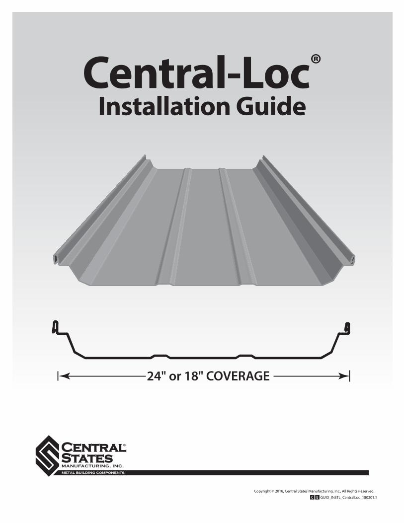
24" or 18" COVERAGE
16" or 18" COVERAGE
3"
3"
24" or 18" COVERAGE
1¾"
16" COVERAGE
2"
Central-Loc®
Installation Guide
GUID_INSTL_CentralLoc_180201.1C E
Copyright © 2018, Central States Manufacturing, Inc., All Rights Reserved.
C E N T R A L S T A T E S M A N U F A C T U R I N G , I N C .E f f e c t i v e 2 / 2 0 1 8 • I n f o r m a t i o n s u b j e c t t o c h a n g e 3
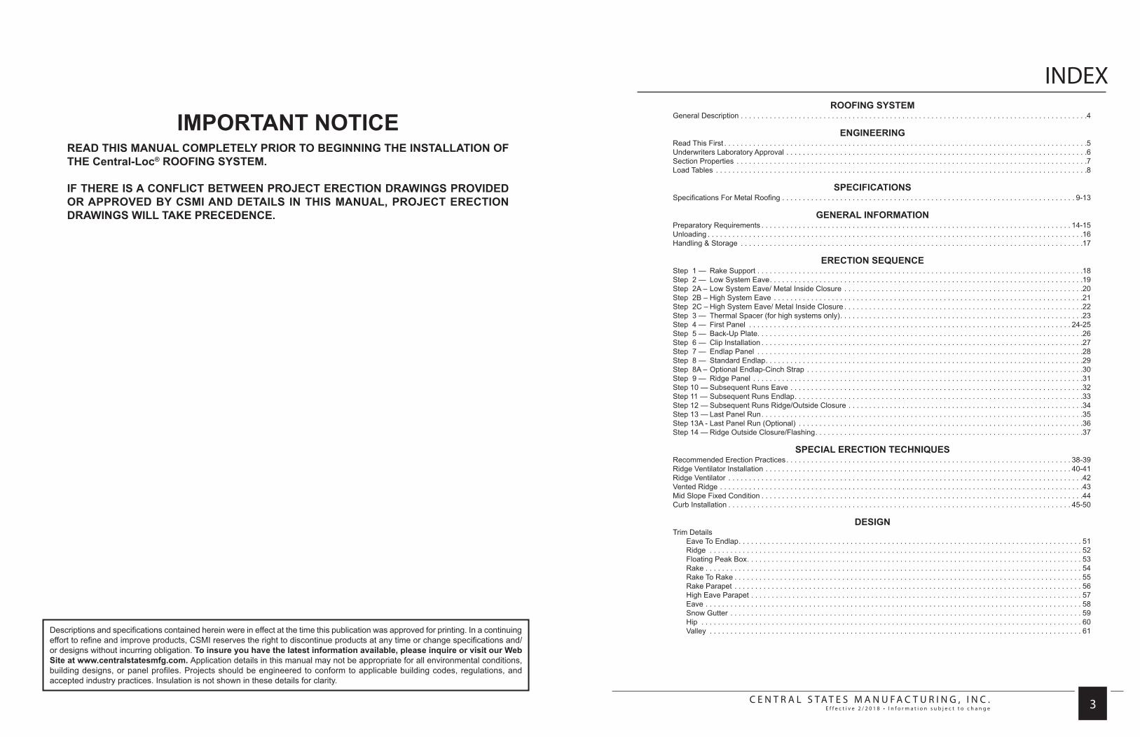
INDEX
Descriptions and specifications contained herein were in effect at the time this publication was approved for printing. In a continuing effort to refine and improve products, CSMI reserves the right to discontinue products at any time or change specifications and/or designs without incurring obligation. To insure you have the latest information available, please inquire or visit our Web Site at www.centralstatesmfg.com. Application details in this manual may not be appropriate for all environmental conditions, building designs, or panel profiles. Projects should be engineered to conform to applicable building codes, regulations, and accepted industry practices. Insulation is not shown in these details for clarity.
IMPORTANT NOTICEREAD THIS MANUAL COMPLETELY PRIOR TO BEGINNING THE INSTALLATION OF THE Central-Loc® ROOFING SYSTEM.
IF THERE IS A CONFLICT BETWEEN PROJECT ERECTION DRAWINGS PROVIDED OR APPROVED BY CSMI AND DETAILS IN THIS MANUAL, PROJECT ERECTION DRAWINGS WILL TAKE PRECEDENCE.
ROOFING SYSTEMGeneral Description . . . . . . . . . . . . . . . . . . . . . . . . . . . . . . . . . . . . . . . . . . . . . . . . . . . . . . . . . . . . . . . . . . . . . . . . . . . . . . . . . . . .4
ENGINEERINGRead This First . . . . . . . . . . . . . . . . . . . . . . . . . . . . . . . . . . . . . . . . . . . . . . . . . . . . . . . . . . . . . . . . . . . . . . . . . . . . . . . . . . . . . . . .5Underwriters Laboratory Approval . . . . . . . . . . . . . . . . . . . . . . . . . . . . . . . . . . . . . . . . . . . . . . . . . . . . . . . . . . . . . . . . . . . . . . . . .6Section Properties . . . . . . . . . . . . . . . . . . . . . . . . . . . . . . . . . . . . . . . . . . . . . . . . . . . . . . . . . . . . . . . . . . . . . . . . . . . . . . . . . . . . .7Load Tables . . . . . . . . . . . . . . . . . . . . . . . . . . . . . . . . . . . . . . . . . . . . . . . . . . . . . . . . . . . . . . . . . . . . . . . . . . . . . . . . . . . . . . . . . .8
SPECIFICATIONSSpecifications For Metal Roofing . . . . . . . . . . . . . . . . . . . . . . . . . . . . . . . . . . . . . . . . . . . . . . . . . . . . . . . . . . . . . . . . . . . . . . . 9-13
GENERAL INFORMATIONPreparatory Requirements . . . . . . . . . . . . . . . . . . . . . . . . . . . . . . . . . . . . . . . . . . . . . . . . . . . . . . . . . . . . . . . . . . . . . . . . . . . 14-15Unloading . . . . . . . . . . . . . . . . . . . . . . . . . . . . . . . . . . . . . . . . . . . . . . . . . . . . . . . . . . . . . . . . . . . . . . . . . . . . . . . . . . . . . . . . . . .16Handling & Storage . . . . . . . . . . . . . . . . . . . . . . . . . . . . . . . . . . . . . . . . . . . . . . . . . . . . . . . . . . . . . . . . . . . . . . . . . . . . . . . . . . .17
ERECTION SEQUENCEStep 1 — Rake Support . . . . . . . . . . . . . . . . . . . . . . . . . . . . . . . . . . . . . . . . . . . . . . . . . . . . . . . . . . . . . . . . . . . . . . . . . . . . . . .18Step 2 — Low System Eave. . . . . . . . . . . . . . . . . . . . . . . . . . . . . . . . . . . . . . . . . . . . . . . . . . . . . . . . . . . . . . . . . . . . . . . . . . . .19Step 2A – Low System Eave/ Metal Inside Closure . . . . . . . . . . . . . . . . . . . . . . . . . . . . . . . . . . . . . . . . . . . . . . . . . . . . . . . . . .20Step 2B – High System Eave . . . . . . . . . . . . . . . . . . . . . . . . . . . . . . . . . . . . . . . . . . . . . . . . . . . . . . . . . . . . . . . . . . . . . . . . . . .21Step 2C – High System Eave/ Metal Inside Closure . . . . . . . . . . . . . . . . . . . . . . . . . . . . . . . . . . . . . . . . . . . . . . . . . . . . . . . . . .22Step 3 — Thermal Spacer (for high systems only). . . . . . . . . . . . . . . . . . . . . . . . . . . . . . . . . . . . . . . . . . . . . . . . . . . . . . . . . . .23Step 4 — First Panel . . . . . . . . . . . . . . . . . . . . . . . . . . . . . . . . . . . . . . . . . . . . . . . . . . . . . . . . . . . . . . . . . . . . . . . . . . . . . . 24-25Step 5 — Back-Up Plate. . . . . . . . . . . . . . . . . . . . . . . . . . . . . . . . . . . . . . . . . . . . . . . . . . . . . . . . . . . . . . . . . . . . . . . . . . . . . . .26Step 6 — Clip Installation . . . . . . . . . . . . . . . . . . . . . . . . . . . . . . . . . . . . . . . . . . . . . . . . . . . . . . . . . . . . . . . . . . . . . . . . . . . . . .27Step 7 — Endlap Panel . . . . . . . . . . . . . . . . . . . . . . . . . . . . . . . . . . . . . . . . . . . . . . . . . . . . . . . . . . . . . . . . . . . . . . . . . . . . . . .28Step 8 — Standard Endlap. . . . . . . . . . . . . . . . . . . . . . . . . . . . . . . . . . . . . . . . . . . . . . . . . . . . . . . . . . . . . . . . . . . . . . . . . . . . .29Step 8A – Optional Endlap-Cinch Strap . . . . . . . . . . . . . . . . . . . . . . . . . . . . . . . . . . . . . . . . . . . . . . . . . . . . . . . . . . . . . . . . . . .30Step 9 — Ridge Panel . . . . . . . . . . . . . . . . . . . . . . . . . . . . . . . . . . . . . . . . . . . . . . . . . . . . . . . . . . . . . . . . . . . . . . . . . . . . . . . .31Step 10 — Subsequent Runs Eave . . . . . . . . . . . . . . . . . . . . . . . . . . . . . . . . . . . . . . . . . . . . . . . . . . . . . . . . . . . . . . . . . . . . . . .32Step 11 — Subsequent Runs Endlap. . . . . . . . . . . . . . . . . . . . . . . . . . . . . . . . . . . . . . . . . . . . . . . . . . . . . . . . . . . . . . . . . . . . . .33Step 12 — Subsequent Runs Ridge/Outside Closure . . . . . . . . . . . . . . . . . . . . . . . . . . . . . . . . . . . . . . . . . . . . . . . . . . . . . . . . .34Step 13 — Last Panel Run. . . . . . . . . . . . . . . . . . . . . . . . . . . . . . . . . . . . . . . . . . . . . . . . . . . . . . . . . . . . . . . . . . . . . . . . . . . . . .35Step 13A - Last Panel Run (Optional) . . . . . . . . . . . . . . . . . . . . . . . . . . . . . . . . . . . . . . . . . . . . . . . . . . . . . . . . . . . . . . . . . . . . .36Step 14 — Ridge Outside Closure/Flashing. . . . . . . . . . . . . . . . . . . . . . . . . . . . . . . . . . . . . . . . . . . . . . . . . . . . . . . . . . . . . . . . .37
SPECIAL ERECTION TECHNIQUESRecommended Erection Practices. . . . . . . . . . . . . . . . . . . . . . . . . . . . . . . . . . . . . . . . . . . . . . . . . . . . . . . . . . . . . . . . . . . . . 38-39Ridge Ventilator Installation . . . . . . . . . . . . . . . . . . . . . . . . . . . . . . . . . . . . . . . . . . . . . . . . . . . . . . . . . . . . . . . . . . . . . . . . . . 40-41Ridge Ventilator . . . . . . . . . . . . . . . . . . . . . . . . . . . . . . . . . . . . . . . . . . . . . . . . . . . . . . . . . . . . . . . . . . . . . . . . . . . . . . . . . . . . . .42Vented Ridge . . . . . . . . . . . . . . . . . . . . . . . . . . . . . . . . . . . . . . . . . . . . . . . . . . . . . . . . . . . . . . . . . . . . . . . . . . . . . . . . . . . . . . . .43Mid Slope Fixed Condition . . . . . . . . . . . . . . . . . . . . . . . . . . . . . . . . . . . . . . . . . . . . . . . . . . . . . . . . . . . . . . . . . . . . . . . . . . . . . .44Curb Installation . . . . . . . . . . . . . . . . . . . . . . . . . . . . . . . . . . . . . . . . . . . . . . . . . . . . . . . . . . . . . . . . . . . . . . . . . . . . . . . . . . . 45-50
DESIGNTrim Details
Eave To Endlap . . . . . . . . . . . . . . . . . . . . . . . . . . . . . . . . . . . . . . . . . . . . . . . . . . . . . . . . . . . . . . . . . . . . . . . . . . . . . . . . . . . 51Ridge . . . . . . . . . . . . . . . . . . . . . . . . . . . . . . . . . . . . . . . . . . . . . . . . . . . . . . . . . . . . . . . . . . . . . . . . . . . . . . . . . . . . . . . . . . 52Floating Peak Box . . . . . . . . . . . . . . . . . . . . . . . . . . . . . . . . . . . . . . . . . . . . . . . . . . . . . . . . . . . . . . . . . . . . . . . . . . . . . . . . . 53Rake . . . . . . . . . . . . . . . . . . . . . . . . . . . . . . . . . . . . . . . . . . . . . . . . . . . . . . . . . . . . . . . . . . . . . . . . . . . . . . . . . . . . . . . . . . . 54Rake To Rake . . . . . . . . . . . . . . . . . . . . . . . . . . . . . . . . . . . . . . . . . . . . . . . . . . . . . . . . . . . . . . . . . . . . . . . . . . . . . . . . . . . . 55Rake Parapet . . . . . . . . . . . . . . . . . . . . . . . . . . . . . . . . . . . . . . . . . . . . . . . . . . . . . . . . . . . . . . . . . . . . . . . . . . . . . . . . . . . . 56High Eave Parapet . . . . . . . . . . . . . . . . . . . . . . . . . . . . . . . . . . . . . . . . . . . . . . . . . . . . . . . . . . . . . . . . . . . . . . . . . . . . . . . . 57Eave . . . . . . . . . . . . . . . . . . . . . . . . . . . . . . . . . . . . . . . . . . . . . . . . . . . . . . . . . . . . . . . . . . . . . . . . . . . . . . . . . . . . . . . . . . . 58Snow Gutter . . . . . . . . . . . . . . . . . . . . . . . . . . . . . . . . . . . . . . . . . . . . . . . . . . . . . . . . . . . . . . . . . . . . . . . . . . . . . . . . . . . . . 59Hip . . . . . . . . . . . . . . . . . . . . . . . . . . . . . . . . . . . . . . . . . . . . . . . . . . . . . . . . . . . . . . . . . . . . . . . . . . . . . . . . . . . . . . . . . . . . 60Valley . . . . . . . . . . . . . . . . . . . . . . . . . . . . . . . . . . . . . . . . . . . . . . . . . . . . . . . . . . . . . . . . . . . . . . . . . . . . . . . . . . . . . . . . . . 61
C E N T R A L S T A T E S M A N U F A C T U R I N G , I N C .E f f e c t i v e 2 / 2 0 1 8 • I n f o r m a t i o n s u b j e c t t o c h a n g e
C E N T R A L S T A T E S M A N U F A C T U R I N G , I N C .E f f e c t i v e 2 / 2 0 1 8 • I n f o r m a t i o n s u b j e c t t o c h a n g e 4 5
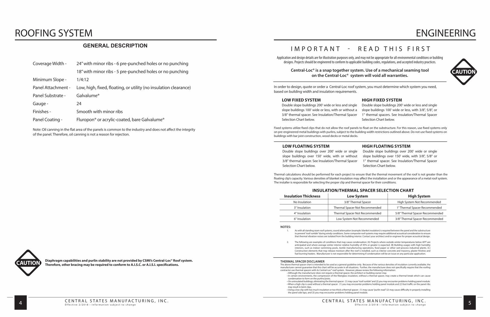
ROOFING SYSTEMGENERAL DESCRIPTION
Coverage Width - 24” with minor ribs - 6 pre-punched holes or no punching
18” with minor ribs - 5 pre-punched holes or no punching
Minimum Slope - 1/4:12
Panel Attachment - Low, high, fixed, floating, or utility (no insulation clearance)
Panel Substrate - Galvalume®
Gauge - 24
Finishes - Smooth with minor ribs
Panel Coating - Fluropon® or acrylic-coated, bare Galvalume®
Note: Oil canning in the flat area of the panels is common to the industry and does not affect the integrity of the panel. Therefore, oil canning is not a reason for rejection.
CAUTION Diaphragm capabilities and purlin stability are not provided by CSMI’s Central-Loc® Roof system.Therefore, other bracing may be required to conform to A.I.S.C. or A.I.S.I. specifications.
ENGINEERING
Application and design details are for illustration purposes only, and may not be appropriate for all environmental conditions or building designs. Projects should be engineered to conform to applicable building codes, regulations, and accepted industry practices.
CAUTION
I M P O R T A N T - R E A D T H I S F I R S T
Central-Loc® is a snap together system. Use of a mechanical seaming toolon the Central-Loc® system will void all warranties.
LOW FIXED SYSTEMDouble slope buildings 200' wide or less and single slope buildings 100' wide or less, with or without a 3/8" thermal spacer. See Insulation/Thermal Spacer Selection Chart below.
HIGH FIXED SYSTEMDouble slope buildings 200' wide or less and single slope buildings 100' wide or less, with 3/8", 5/8", or 1" thermal spacers. See Insulation/Thermal Spacer Selection Chart below.
In order to design, quote or order a Central-Loc roof system, you must determine which system you need, based on building width and insulation requirements.
Thermal calculations should be performed for each project to ensure that the thermal movement of the roof is not greater than the floating clip’s capacity. Various densities of blanket insulation may affect the installation and or the appearance of a metal roof system. The installer is responsible for selecting the proper clip and thermal spacer for their conditions.
Fixed systems utilize fixed clips that do not allow the roof panels to float on the substructure. For this reason, use fixed systems only on pre-engineered metal buildings with purlins, subject to the building width restrictions outlined above. Do not use fixed systems on buildings with bar joist construction, wood decks or metal decks.
LOW FLOATING SYSTEMDouble slope buildings over 200' wide or single slope buildings over 150' wide, with or without 3/8" thermal spacer. See Insulation/Thermal Spacer Selection Chart below.
HIGH FLOATING SYSTEM Double slope buildings over 200' wide or single slope buildings over 150' wide, with 3/8", 5/8" or 1" thermal spacer. See Insulation/Thermal Spacer Selection Chart below.
INSULATION/THERMAL SPACER SELECTION CHART Insulation Thickness Low System High System No Insulation 3/8" Thermal Spacer High System Not Recommended
3" Insulation Thermal Spacer Not Recommended 1" Thermal Spacer Recommended
4" Insulation Thermal Spacer Not Recommended 5/8" Thermal Spacer Recommended
6" Insulation Low System Not Recommended 3/8" Thermal Spacer Recommended
NOTES: 1. As with all standing seam roof systems, sound attenuation (example: blanket insulation) is required between the panel and the substructure
to prevent “roof rumble” during windy conditions. Some composite roof systems may require additional acoustical consideration to ensure that thermal vibration noises are isolated from the building interior. Contact your architect and/or engineer for proper acoustical design.
2. The following are examples of conditions that may cause condensation: (A) Projects where outside winter temperatures below 40°F are anticipated and where average winter interior relative humidity of 45% or greater is expected. (B) Building usages with high humidity interiors, such as indoor swimming pools, textile manufacturing operations, food paper or other wet-process industrial plants. (C) Construction elements that may release moisture after the roof is installed, such as interior concrete and masonry, plaster finishes and fuel burning heaters. Manufacturer is not responsible for determining if condensation will be an issue on any particular application.
THERMAL SPACER DISCLAIMERThe above thermal spacer chart is intended to be used as a general guideline only. Because of the various densities of insulation currently available, the manufacturer cannot guarantee that this chart will be accurate in all situations. Further, the manufacturer does not specifically require that the roofing contractor use thermal spacers with its Central-Loc® roof system. However, please review the following information: • Although the manufacturer does not require a thermal spacer, the architect or building owner may. • In certain environments, the compression of the fiberglass insulation, without a thermal spacer, may create a thermal break which can cause
condensation to form on the purlins/joists. • On uninsulated buildings, eliminating the thermal spacer: (1) may cause “roof rumble” and (2) you may encounter problems holding panel module. • When a high clip is used without a thermal spacer: (1) you may encounter problems holding panel module and (2) foot traffic on the panel ribs
may result in bent clips. • Using a low clip with too much insulation or too thick a thermal spacer: (1) may cause “purlin read” (2) may cause difficulty in properly installing
the panel side laps, and (3) you may encounter problems holding panel module.
C E N T R A L S T A T E S M A N U F A C T U R I N G , I N C .E f f e c t i v e 2 / 2 0 1 8 • I n f o r m a t i o n s u b j e c t t o c h a n g e
C E N T R A L S T A T E S M A N U F A C T U R I N G , I N C .E f f e c t i v e 2 / 2 0 1 8 • I n f o r m a t i o n s u b j e c t t o c h a n g e 6 7
ENGINEERING ENGINEERING
The Engineering data contained herein is for the expressed use of customers and design professionals. Along with this data, it is recommended that the design professional have a copy of the most current version of the North American Specification for the design of Cold-Formed Steel Structural Members published by the American Iron and Steel Institute to facilitate design. This specification contains the design criteria for cold-formed steel components. Along with the specification, the designer should reference the most current building code applicable to the project jobsite in order to determine environmental loads. If further information or guidance regarding cold-formed design practices is desired, please contact the manufacturer.
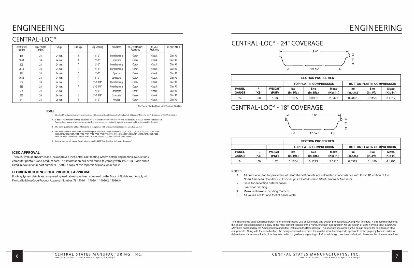
SECTION PROPERTIES
TOP FLAT IN COMPRESSION BOTTOM FLAT IN COMPRESSION PANEL Fy WEIGHT Ixe Sxe Maxo Ixe Sxe Maxo GAUGE (KSI) (PSF) (in.4/ft.) (in.3/ft.) (Kip in.) (in.4/ft.) (in.3/ft.) (Kip in.)
24 50 1.23 0.1355 0.0951 2.8477 0.2803 0.1156 3.4612
NOTES: 1. All calculation for the properties of Central-Loc® panels are calculated in accordance with the 2001 edition of the North American Specification For Design Of Cold-Formed Steel Structural Members. 2. Ixe is for deflection determination. 3. Sxe is for bending. 4. Maxo is allowable bending moment. 5. All values are for one foot of panel width.
19 3/8”
24”
3”
13 3/8”
18”
3”
SECTION PROPERTIES
TOP FLAT IN COMPRESSION BOTTOM FLAT IN COMPRESSION PANEL Fy WEIGHT Ixe Sxe Maxo Ixe Sxe Maxo GAUGE (KSI) (PSF) (in.4/ft.) (in.3/ft.) (Kip in.) (in.4/ft.) (in.3/ft.) (Kip in.)
24 50 1.32 0.1804 0.1273 3.8115 0.3372 0.1480 4.4295
Constructionnumber
165180B205
205A286
308B534535536537541
Panel Width (Inches)
2424242424242424242424
Gauge
24 min.24 min.24 min.24 min.24 min.24 min.24 min.24 min.24 min.24 min.26 min.
Clip Type
BAABCABABBB
Clip Spacing
5’-0”5’-0”5’-0”5’-0”5’-0”5’-0”
5’-0 1/4”5’-0 1/4”
5’-0”5’-0 1/4”
5’-0”
Substrate
Open FramingComposite
Open FramingOpen Framing
PlywoodComposite
Open FramingOpen Framing
CompositeCompositePlywood
UL-2218 Impact Resistance
Class 4Class 4Class 4Class 4Class 4Class 4Class 4Class 4Class 4Class 4Class 4
UL-263Fire Rating
Class A Class AClass AClass AClass AClass AClass AClass AClass AClass AClass A
UL-580 Rating
Class 90Class 90Class 90Class 90Class 90Class 90Class 90Class 90Class 90Class 90Class 90
NOTES: 1. Wind uplift test procedures are in accordance with Underwriters Laboratories Standard UL-580 under “Tests For Uplift Resistance of Roof Assemblies.” 2. A detailed installation method is available for each Construction Number above and can be found in the UL Roofing Materials and Systems Directory or at http://www.ul.com. The panels must be installed in a certain manner to achieve the published results.
3. The panel qualifies for a Class A fire rating in compliance with Underwriters Laboratories Standard UL-263.
4. The panel system is listed under the following Fire Resistance Design Numbers: P224, P225, P227, P230, P233, P237, P265, P268, P508, P510, P512, P701, P711, P715, P717, P720, P722, P724, P726, P731, P734, P736, P801, P803, P814, P815, P819, P821, P823. Refer to the UL Fire Resistance Directory for specific construction methods and hourly ratings. 5. Central-Loc® panels carry a Class 4 rating under UL-2218 “Test Standard for Impact Resistance”.
Clip Type: A (Fixed or Floating); B (Floating); C (Utility).
CENTRAL-LOC®
ICBO APPROVALThe ICBO Evaluation Service, Inc., has approved the Central-Loc® roofing system details, engineering, calculations, computer printouts and product data. This information has been found to comply with 1997 UBC Code and is listed in evaluation report number ER-5409. A copy of this report is available on request.
FLORIDA BUILDING CODE PRODUCT APPROVALRoofing System details and engineering load tables have been examined by the State of Florida and comply with Florida Building Code Product Approval Number (FL 14016.1, 14026.1, 14026.2, 14026.3).
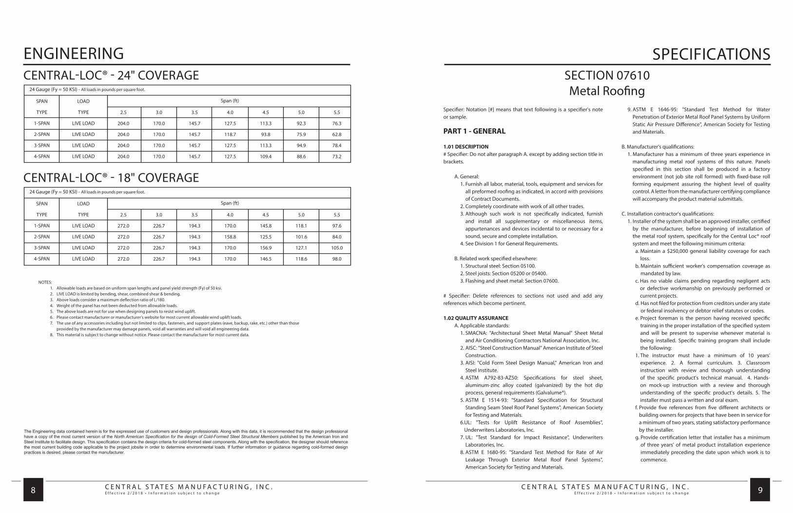
CENTRAL-LOC® - 24" COVERAGE
CENTRAL-LOC® - 18" COVERAGE19 3/8”
24”
3”
13 3/8”
18”
3”
C E N T R A L S T A T E S M A N U F A C T U R I N G , I N C .E f f e c t i v e 2 / 2 0 1 8 • I n f o r m a t i o n s u b j e c t t o c h a n g e
C E N T R A L S T A T E S M A N U F A C T U R I N G , I N C .E f f e c t i v e 2 / 2 0 1 8 • I n f o r m a t i o n s u b j e c t t o c h a n g e 8 9
ENGINEERING
The Engineering data contained herein is for the expressed use of customers and design professionals. Along with this data, it is recommended that the design professional have a copy of the most current version of the North American Specification for the design of Cold-Formed Steel Structural Members published by the American Iron and Steel Institute to facilitate design. This specification contains the design criteria for cold-formed steel components. Along with the specification, the designer should reference the most current building code applicable to the project jobsite in order to determine environmental loads. If further information or guidance regarding cold-formed design practices is desired, please contact the manufacturer.
NOTES: 1. Allowable loads are based on uniform span lengths and panel yield strength (Fy) of 50 ksi. 2. LIVE LOAD is limited by bending, shear, combined shear & bending. 3. Above loads consider a maximum deflection ratio of L/180. 4. Weight of the panel has not been deducted from allowable loads. 5. The above loads are not for use when designing panels to resist wind uplift. 6. Please contact manufacturer or manufacturer’s website for most current allowable wind uplift loads. 7. The use of any accessories including but not limited to clips, fasteners, and support plates (eave, backup, rake, etc.) other than those provided by the manufacturer may damage panels, void all warranties and will void all engineering data. 8. This material is subject to change without notice. Please contact the manufacturer for most current data.
SPECIFICATIONS
SPAN
TYPE
1-SPAN
2-SPAN
3-SPAN
4-SPAN
LOAD
TYPE
LIVE LOAD
LIVE LOAD
LIVE LOAD
LIVE LOAD
2.5
204.0
204.0
204.0
204.0
3.0
170.0
170.0
170.0
170.0
3.5
145.7
145.7
145.7
145.7
4.0
127.5
118.7
127.5
127.5
4.5
113.3
93.8
113.3
109.4
5.0
92.3
75.9
94.9
88.6
5.5
76.3
62.8
78.4
73.2
Span (ft)
24 Gauge (Fy = 50 KSI) - All loads in pounds per square foot.
CENTRAL-LOC® - 24" COVERAGE
SPAN
TYPE
1-SPAN
2-SPAN
3-SPAN
4-SPAN
LOAD
TYPE
LIVE LOAD
LIVE LOAD
LIVE LOAD
LIVE LOAD
2.5
272.0
272.0
272.0
272.0
3.0
226.7
226.7
226.7
226.7
3.5
194.3
194.3
194.3
194.3
4.0
170.0
158.8
170.0
170.0
4.5
145.8
125.5
156.9
146.5
5.0
118.1
101.6
127.1
118.6
5.5
97.6
84.0
105.0
98.0
Span (ft)
24 Gauge (Fy = 50 KSI) - All loads in pounds per square foot.
CENTRAL-LOC® - 18" COVERAGE
Specifier: Notation [#] means that text following is a specifier's note or sample.
PART 1 - GENERAL
1.01 DESCRIPTION # Specifier: Do not alter paragraph A. except by adding section title in brackets. A. General: 1. Furnish all labor, material, tools, equipment and services for
all preformed roofing as indicated, in accord with provisions of Contract Documents.
2. Completely coordinate with work of all other trades. 3. Although such work is not specifically indicated, furnish
and install all supplementary or miscellaneous items, appurtenances and devices incidental to or necessary for a sound, secure and complete installation.
4. See Division 1 for General Requirements.
B. Related work specified elsewhere: 1. Structural steel: Section 05100. 2. Steel joists: Section 05200 or 05400. 3. Flashing and sheet metal: Section 07600.
# Specifier: Delete references to sections not used and add any references which become pertinent.
1.02 QUALITY ASSURANCE A. Applicable standards: 1. SMACNA: "Architectural Sheet Metal Manual" Sheet Metal
and Air Conditioning Contractors National Association, Inc. 2. AISC: "Steel Construction Manual" American Institute of Steel
Construction. 3. AISI: "Cold Form Steel Design Manual," American Iron and
Steel Institute. 4. ASTM A792-83-AZ50: Specifications for steel sheet,
aluminum-zinc alloy coated (galvanized) by the hot dip process, general requirements (Galvalume®).
5. ASTM E 1514-93: "Standard Specification for Structural Standing Seam Steel Roof Panel Systems", American Society for Testing and Materials.
6. UL: "Tests for Uplift Resistance of Roof Assemblies", Underwriters Laboratories, Inc.
7. UL: "Test Standard for Impact Resistance", Underwriters Laboratories, Inc.
8. ASTM E 1680-95: "Standard Test Method for Rate of Air Leakage Through Exterior Metal Roof Panel Systems", American Society for Testing and Materials.
9. ASTM E 1646-95: "Standard Test Method for Water Penetration of Exterior Metal Roof Panel Systems by Uniform Static Air Pressure Difference", American Society for Testing and Materials.
B. Manufacturer's qualifications: 1. Manufacturer has a minimum of three years experience in
manufacturing metal roof systems of this nature. Panels specified in this section shall be produced in a factory environment (not job site roll formed) with fixed-base roll forming equipment assuring the highest level of quality control. A letter from the manufacturer certifying compliance will accompany the product material submittals.
C. Installation contractor's qualifications: 1. Installer of the system shall be an approved installer, certified
by the manufacturer, before beginning of installation of the metal roof system, specifically for the Central Loc® roof system and meet the following minimum criteria:
a. Maintain a $250,000 general liability coverage for each loss.
b. Maintain sufficient worker's compensation coverage as mandated by law.
c. Has no viable claims pending regarding negligent acts or defective workmanship on previously performed or current projects.
d. Has not filed for protection from creditors under any state or federal insolvency or debtor relief statutes or codes.
e. Project foreman is the person having received specific training in the proper installation of the specified system and will be present to supervise whenever material is being installed. Specific training program shall include the following:
1. The instructor must have a minimum of 10 years' experience. 2. A formal curriculum. 3. Classroom instruction with review and thorough understanding of the specific product's technical manual. 4. Hands-on mock-up instruction with a review and thorough understanding of the specific product's details. 5. The installer must pass a written and oral exam.
f. Provide five references from five different architects or building owners for projects that have been in service for a minimum of two years, stating satisfactory performance by the installer.
g. Provide certification letter that installer has a minimum of three years' of metal product installation experience immediately preceding the date upon which work is to commence.
SECTION 07610Metal Roofing

C E N T R A L S T A T E S M A N U F A C T U R I N G , I N C .E f f e c t i v e 2 / 2 0 1 8 • I n f o r m a t i o n s u b j e c t t o c h a n g e
C E N T R A L S T A T E S M A N U F A C T U R I N G , I N C .E f f e c t i v e 2 / 2 0 1 8 • I n f o r m a t i o n s u b j e c t t o c h a n g e 10 11
SPECIFICATIONS SPECIFICATIONS D. Pre-installation Conference: 1. Prior to installation of roofing system, conduct a pre-
installation conference at the project site. 2. Attendance: Owner, Architect, Contractor, Project
Superintendent, and Roof Applicator 3. Agenda: a. Roofing details and agenda b. Critical work sequencing and review of phasing plan c. Inspection sequencing
1.03 SYSTEM PERFORMANCE REQUIREMENTS A. Performance Testing: 1. Metal roof system must be tested in accordance with
Underwriters Laboratories, Inc. (UL) Test Method 580 “Tests for Uplift Resistance of Roof Assemblies”.
2. Metal roof system must be installed in accordance with UL Construction method [# choose one]:
q 180B (min. 14 gauge purlin, 5’-0” on center max. with 29 gauge “D” panel and low/high fixed/floating/ articulating clips. Rigid insulation to be min. 1” thick) or
q 205 (min. 16 gauge purlin, 5’-0” on center max. with low/high fixed/floating clips) or
q 205A (min. 16 gauge purlin, 5’-0” on center max with articulating clips, with Light Transmitting Panels) or
q 286 (min. 5/8” plywood deck with fixed/articulating clips at 5’-0” on center max.) or
q 308B (min. 14 gauge purlin, 5’-0” on center max., min. 1” thick rigid insulation and 22 gauge 1 1/2” deep metal deck with fixed, floating or articulating clips at 5’¬0” on center max.) or
q 534 (min. 16 gauge purlin, 5’-0 1/4” on center max. with low/high floating/articulating clips with Light Transmitting Panels) or
q 535 (min. 16 gauge purlin, 5’-0 1/4” on center max. with low/high fixed/floating clips without Light Transmitting Panels) or
q 536 (min. 1” thick rigid insulation and min. 22 gauge Type A, B, F, or N metal deck with low/high floating/ articulating clips at 5’-0” on center max.).or
q 537 (min. 16 gauge purlin, 5’-0 1/4” on center max., min. 1” thick rigid insulation and 29 gauge 9/16” deep metal deck with floating clips at 5’-0 1/4” on center max.) or
q 541 (min. 5/8” plywood deck with low/high floating/ articulating clips at 5’-0” on center max.). See the current UL Roofing Materials and Systems Directory for requirements of each Construction Method.
3. Resist the roof design pressures calculated in accordance with [# choose one: SBBCI, UBC, BOCA, ASCE or an applicable national or local building code].Determine panel bending and clip-to-panel strength by testing in accordance with ASTM E 1592-95. Capacity for gauge, span or loading other than those tested may be determined by interpolating test results.
4. Metal roof system must meet the air infiltration requirements of ASTM E 1680-95 when tested with a 6.24 PSF pressure differential with resulting air infiltration of 0.251 cfm/sq ft.
5. Metal roof system must meet the water penetration requirements of ASTM E 1646-95 when tested with a 12.00 PSF pressure differential with no uncontrollable water leakage when five gallons per hour of water is sprayed per square foot of roof area.
6. Metal roof system must qualify for a Class 4 rating when tested in accordance with Underwriters Laboratories, Inc. UL-2218 “Test Standard For Impact Resistance.”
# Specifier: Select construction method for paragraph A.1. and applicable building code for paragraph A.2.
1.04 DESIGN REQUIREMENTS A. Roof Design Loads: 1. Design criteria shall be in accordance with [# choose one:
MBMA, SBBCI, UBC, BOCA, ASCE or an applicable national or local building code.]
2. Dead Loads a. The dead load shall be the weight of the SSSMR system.
Collateral loads, such as sprinklers, mechanical and electrical systems, and ceilings shall not be attached to the panels.
3. Live Loads a. The panels and concealed anchor clips shall be capable of
supporting a minimum uniform live load of -20 psf. 4. Roof Snow Loads a. The design roof snow loads shall be as shown on the
contract drawings. 5. Wind Loads a. The design wind uplift for the roof system shall be as
shown on the contract drawings. The design uplift force for each connection assembly shall be that pressure given for the area under consideration, multiplied by the tributary load area of the connection assembly. The safety factor listed below shall be applied to the design force and compared against the ultimate capacity. Prying shall be considered when calculating fastener design loads.
aa. Single fastener in each connection - 3.0 bb. Two or more fasteners in each connection. - 2.25 6. Thermal Loads a. Roof panels shall be free to move in response to the
expansion and contraction forces resulting from a total temperature range of ____°F during the life of the structure. [Choose temperature differential based on Max. and Min. for specific area IAW MBMA Climatological Data]
# Specifier: Select applicable building code for paragraph A.1 Select Temperature differential for paragraph A.6. B. Framing Members Supporting the SSSMR System 1. Any additions/revisions to framing members supporting
the SSSMR system to accommodate the manufacturer/fabricator’s design shall be submitted for review and approval. New or revised framing members and their connections shall be designed in accordance with [\-AISC-\] [\-AISI-\] [\-SJI-\] design specifications. Maximum deflection under applied live load, snow, or wind load shall not exceed [choose one: L/180, U240] of the span length.
1.05 SUBMITTALS A. Shop drawings: 1. Submit complete shop drawings and erection details,
approved by the metal roofing manufacturer, to the architect (owner) for review. Do not proceed with manufacture of roofing materials prior to review of shop drawings and field verification of all dimensions. Do not use drawings prepared by the architect (owner) for shop or erection drawings.
2. Shop drawings show methods of erection, elevations and plans of roof and wall panels, sections and details, anticipated loads, flashings, roof curbs, vents, sealants, interfaces with all materials not supplied and proposed identification of component parts and their finishes.
B. Performance Tests: 1. Submit certified test results by a recognized testing
laboratory or manufacturer’s lab (witnessed by a professional engineer) in accordance with specified test methods for each panel system.
C. Calculations: 1. Submit engineering calculations defining cladding loads for
all roof areas based on specified building codes, allowable clip loads and required number of fasteners to secure the panel clips to the designated substructure.
2. Compute uplift loads on clip fasteners with full recognition of prying forces and eccentric clip loading.
3. Calculate holding strength of fasteners in accordance with submitted test data provided by Fastener Manufacturer based on length of embedment and properties of materials.
4. Submit drainage calculations for valley, gutter, and downspout designs for a rainfall intensity (inches per hour) of [# choose one: 5 year or 25 year recurrence] for a 5 minute duration. (See MBMA Low Rise Building Systems Design Manual Section A22 for Wind, Snow, Seismic, and Rain Data by County)
5. Submit thermal calculations and details of floating clip, flashing attachments, and accessories certifying the free movement in response to the expansion/ contraction forces resulting from a total temperature differential of 110° F.
D. Samples: 1. Submit samples and color chips for all proposed finishes. a. Submit one 8 inch long sample of panel, including clips. b. Submit two 3 inch x 5 inch color chip samples in color
selected by the architect (owner).
E. Warranty(s): Metal roof system manufacturer, upon final acceptance for
project, furnish a warranty.
1. Covering bare metal against rupture, structural failure and perforation due to normal atmospheric corrosion exposure for a period of 20 years.
2. Covering paint finish against chalking and fading for a period of thirty (30) years for roof panels and wall panels with the CentralGuard™ paint system.
3. Submit specimen copy of manufacturer’s Weathertightness Warranty, including evidence of application for warranty and manufacturer’s acceptance of the applicator and warranty conditions.
F. Test Reports: 1. Submit Test Reports showing that metal panels meet the
air infiltration requirements of ASTM E 1680-95 when tested with a 6.24 PSF pressure differential with resulting air infiltration of 0.251 cfm/sq ft.
2. Submit Test Reports showing that metal panels meet the water penetration requirements of ASTM E 1646¬95 when tested with a 12.00 PSF pressure differential with no uncontrollable water leakage when five gallons per hour of water is sprayed per square foot of roof area.
G. Metal roof system fabrication certification: 1. Submit a letter from the metal panel manufacturer certifying
the Central-Loc® panels have been produced in a factory environment (not job site) with fixed-base roll forming equipment.
H. Installation contractor’s qualifications: 1. Submit certificate from manufacturer certifying that installer
of the metal roof system has met all of the criteria outlined in “1.02 C. Installer’s qualifications” and is an authorized installer certified by the manufacturer within one year of the beginning of installation of the metal roof system.
2. Submit the formal syllabus for the classroom and hands-on training.
3. Submit five references from five different architects or building owners for projects that have been in service for a minimum of two years, stating satisfactory performance by the installation contractor.

C E N T R A L S T A T E S M A N U F A C T U R I N G , I N C .E f f e c t i v e 2 / 2 0 1 8 • I n f o r m a t i o n s u b j e c t t o c h a n g e
C E N T R A L S T A T E S M A N U F A C T U R I N G , I N C .E f f e c t i v e 2 / 2 0 1 8 • I n f o r m a t i o n s u b j e c t t o c h a n g e 12 13
SPECIFICATIONS SPECIFICATIONS1.06 PRODUCT DELIVERY, STORAGE AND HANDLING A. Delivery: 1. Deliver metal roof system to job site properly packaged to
provide protection against transportation damage.
B. Handling: 1. Exercise extreme care in unloading, storing and erecting
metal roof system to prevent bending, warping, twisting and surface damage.
C. Storage: 1. Store all material and accessories above ground on well
skidded platforms. Store under waterproof covering. Provide proper ventilation of metal roof system to prevent condensation build-up between each panel or trim/flashing component.
1.07 WEATHERTIGHTNESS WARRANTY A. The Contractor shall provide to the Owner, a single source
warranty signed by the roofing manufacturer of the Standing Seam Roof System as outlined below:
1. For a period of [choose one: twenty (20), fifteen (15), ten (10), or five (5)] years from the date of substantial completion, the roofing manufacturer WARRANTS to the Building Owner (“Owner”): that the roofing manufacturer’s furnished roof panels, flashing, and related items used to fasten the roof panels and flashing to the roof structure (“Roof System”) will not allow intrusion of water from the exterior of the roofing manufacturer’s Roof System into the building envelope, when exposed to ordinary weather conditions and ordinary wear and usage. The Date of substantial completion is the date that is certified by the Architect, Owner, or Owner’s Representative, when the roofing manufacturer’s Roofing System is completed and accepted by or on behalf of the Owner.
2. The roofing manufacturer shall have the SOLE AND EXCLUSIVE obligation for all warranty work commencing on the date of substantial completion and under all circumstances, terminates on the [# insert appropriate number of years] year anniversary of the date certified as Substantial Completion of the roofing manufacturer’s Roof System. During the period in which the roofing manufacturer has any warranty obligation, the roofing manufacturer shall take appropriate actions necessary to cause the non-performing portions of the Roof System to perform their proper functions.
B. Roofing Manufacturer’s Liability 1. The total liability of the roofing manufacturer under this
warranty is [choose one: limited solely to two (2) times the cost of the roofing manufacturer’s Roof System as invoiced to the roofing manufacturer’s customer, or limited solely to four (4) times the cost of the roofing manufacturer’s Roof System as invoiced to the roofing manufacturer’s customer, or unlimited]. The roofing manufacturer shall have the right to charge to the liability account, all reasonable expenses (including, but not limited to, investigation expenses) incurred in satisfying the requirements of this warranty.
C. Field Quality Control 1. During installation, provide for two on-site inspections of
roof application by qualified technical representative of the manufacturer.
2. Upon completion of installation, provide final inspection by a technical representative of roofing manufacturer to confirm that roofing system has been installed in accordance with manufacturer’s requirements.
3. At completion of project, submit manufacturer’s quality report of field inspections, including final inspection punch list.
PART 2 - PRODUCTS
Central-Loc's structural standing seam metal roof system; minimum slope of 1/4:12
2.01 MATERIALS A. Metal roof system profile: 1. 3 inch high rib x [# choose one: 24 inch or 18 inch] wide
panel.
B. Metal roof system style: 1. Trapezoidal rib, positive snap together, standing seam,
utilizing male and female rib configurations, with factory applied hot melt mastic in female rib.
C. Gauge: [choose one] 1. 22 gauge (UL 90 rated - Underwriters Laboratories). 2. 24 gauge (UL 90 rated - Underwriters Laboratories).
D. Substrate: 1. Galvalume® steel sheet, minimum yield of 50,000 PSI.
E. Clip: 1. Two piece floating clip providing thermal expansion or
contraction (UL 90 rated - Underwriters Laboratories). 2. One piece fixed clip 22 gauge with factory applied mastic (UL
90 rated - Underwriters Laboratories).
D. Curbs shall be constructed to match slope of roof and provide a level top surface for mounting equipment.
E. Curb flanges shall be constructed to match configuration of roof panels.
F. Curb manufacturer will provide their own curb structural support system that can be installed between the purlins that will allow proper thermal movement of the curb with the roofing system.
G. Submit roof curb manufacturer’s shop drawings to metal roof system manufacturer for approval before fabrication of curbs.
2.05 PREFABRICATED ROOF JACKS A. Pipe flashings shall be a one piece [# choose one: EPDM
(ethylene propylene diene monomer) molded rubber boot having a serviceable temperature range of -60°F to 270°F (for standard applications) or neoprene molded rubber boot having a serviceable temperature range of -45°F to 250°F (for exposure to petrochemicals) or silicone molded rubber boot having a serviceable temperature range of -100°F to 450°F (for high temperature applications)] and shall be resistant to ozone and ultraviolet rays. Units shall have an aluminum flanged base ring. Do not install pipe flashings through any panel seams - install ONLY in the flat portion of the panel.
PART 3 - EXECUTION
3.01 SURFACE CONDITIONS A. Examination: 1. Inspect installed work of other trades and verify that such
work is complete to a point where this work may continue. 2. Verify that installation may be made in accordance with
approved shop drawings and manufacturer’s instructions. This specifically includes verifying that secondary structurals and/or decking are installed to meet UL and building code requirements. Coordinate with metal roof system manufacturer to insure that reduced clip spacings at eave, rake, ridge and corner areas are accommodated.
B. Discrepancies: 1. In event of discrepancy, notify the architect (owner). 2. Do not proceed with installation until discrepancies have
been resolved.
3.02 INSTALLATION A. Install metal roof system so that it is weathertight, without
waves, warps, buckles, fastening stresses or distortion, allowing for expansion and contraction.
B. Install metal roof system in accordance with manufacturer’s instructions and shop drawings.
C. Provide concealed anchors at all panel attachment locations. D. Install panels plumb, level and straight with seams and ribs
parallel, conforming to design as indicated.
3.03 ROOF CURB INSTALLATION A. Comply with metal roof system manufacturer’s approved shop
drawings, instructions and recommendations for installation of roof curbs. Refer to metal roof system manufacturer’s standard installation details. Anchor curbs securely in place with provisions for thermal and structural movement.
3.05 CLEANING, PROTECTION A. Dispose of excess materials and remove debris from site. B. Clean work in accordance with manufacturer’s
recommendations. C. Protect work against damage until final acceptance. Replace or
repair to the satisfaction of the architect (owner), any work that becomes damaged prior to final acceptance.
D. Touch up minor scratches and abrasions. E. Do not allow panels or trim to come into contact with dissimilar
metals such as copper, lead, graphite or cast iron. Water run-off from these materials is also prohibited. This specifically includes condensate from roof top A/C units.
END OF SECTION
DISCLAIMER: Central States®makes no warranty, express or implied, as to the merchantability or fitness for any particular purpose of any product manufactured by an optional manufacturer. If you choose to use a product manufactured by an optional manufacturer, as defined herein, you take the product as is and at your own risk. Descriptions and specifications contained herein were in effect at the time this publication was approved for printing. Central States® reserves the right to discontinue products at any time or change specifications and/or designs without notice and without incurring obligation.
To insure you have the latest information available, please contact Central States® or visit www.centralstatesmfg.com.
C E N T R A L S T A T E S M A N U F A C T U R I N G , I N C .E f f e c t i v e 2 / 2 0 1 8 • I n f o r m a t i o n s u b j e c t t o c h a n g e
C E N T R A L S T A T E S M A N U F A C T U R I N G , I N C .E f f e c t i v e 2 / 2 0 1 8 • I n f o r m a t i o n s u b j e c t t o c h a n g e 14 15
GENERAL INFORMATION GENERAL INFORMATION
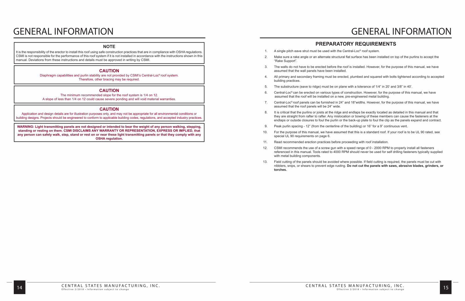
CAUTIONDiaphragm capabilities and purlin stability are not provided by CSMI’s Central-Loc® roof system.
Therefore, other bracing may be required.
CAUTIONThe minimum recommended slope for the roof system is 1/4 on 12.
A slope of less than 1/4 on 12 could cause severe ponding and will void material warranties.
CAUTIONApplication and design details are for illustration purposes only, and may not be appropriate for all environmental conditions or
building designs. Projects should be engineered to conform to applicable building codes, regulations, and accepted industry practices.
WARNING: Light transmitting panels are not designed or intended to bear the weight of any person walking, stepping, standing or resting on them. CSMI DISCLAIMS ANY WARRANTY OR REPRESENTATION, EXPRESS OR IMPLIED, that any person can safely walk, step, stand or rest on or near these light transmitting panels or that they comply with any
OSHA regulation.
NOTEIt is the responsibility of the erector to install this roof using safe construction practices that are in compliance with OSHA regulations. CSMI is not responsible for the performance of this roof system if it is not installed in accordance with the instructions shown in this manual. Deviations from these instructions and details must be approved in writing by CSMI.
PREPARATORY REQUIREMENTS 1. A single pitch eave strut must be used with the Central-Loc® roof system.
2. Make sure a rake angle or an alternate structural flat surface has been installed on top of the purlins to accept the “Rake Support”.
3. The walls do not have to be erected before the roof is installed. However, for the purpose of this manual, we have assumed that the wall panels have been installed.
4. All primary and secondary framing must be erected, plumbed and squared with bolts tightened according to accepted building practices.
5. The substructure (eave to ridge) must be on plane with a tolerance of 1/4” in 20’ and 3/8” in 40’.
6. Central-Loc® can be erected on various types of construction. However, for the purpose of this manual, we have assumed that the roof will be installed on a new, pre-engineered metal building.
7. Central-Loc® roof panels can be furnished in 24” and 18”widths. However, for the purpose of this manual, we have assumed that the roof panels will be 24” wide.
8. It is critical that the purlins or joists at the ridge and endlaps be exactly located as detailed in this manual and that they are straight from rafter to rafter. Any mislocation or bowing of these members can cause the fasteners at the endlaps or outside closures to foul the purlin or the back-up plate to foul the clip as the panels expand and contract.
9. Peak purlin spacing - 12” (from the centerline of the building) or 16” for a 9” continuous vent.
10. For the purpose of this manual, we have assumed that this is a standard roof. If your roof is to be UL 90 rated, see special UL 90 requirements on page 6.
11. Read recommended erection practices before proceeding with roof installation.
12. CSMI recommends the use of a screw gun with a speed range of 0 - 2000 RPM to properly install all fasteners referenced in this manual. Tools rated to 4000 RPM should never be used for self drilling fasteners typically supplied with metal building components.
13. Field cutting of the panels should be avoided where possible. If field cutting is required, the panels must be cut with nibblers, snips, or shears to prevent edge rusting. Do not cut the panels with saws, abrasive blades, grinders, or torches.

C E N T R A L S T A T E S M A N U F A C T U R I N G , I N C .E f f e c t i v e 2 / 2 0 1 8 • I n f o r m a t i o n s u b j e c t t o c h a n g e
C E N T R A L S T A T E S M A N U F A C T U R I N G , I N C .E f f e c t i v e 2 / 2 0 1 8 • I n f o r m a t i o n s u b j e c t t o c h a n g e 16 17
GENERAL INFORMATIONGENERAL INFORMATIONUNLOADING
Upon receiving material, check shipment against shipping list for shortages and damages. CSMI will not be responsible for shortages or damages unless they are noted on the shipping list.
Each bundle should be lifted at its center of gravity. Where possible, bundles should remain banded until final placement on roof. If bundles must be opened, they should be retied before lifting.
When lifting bundles with a crane, a spreader bar and nylon straps should be used. NEVER USE WIRE ROPE OR CHAIN SLINGS. THEY WILL DAMAGE THE PANELS.
When lifting bundles with a forklift, forks must be a minimum of five feet apart. Do not transport open bundles. Drive slowly when crossing rough terrain to prevent panel buckling.
CAUTIONImproper unloading and handling of bundles and crates may cause bodily injury or material damage. The manufacturer is not responsible for bodily injuries or material damages during unloading and storage.
HANDLING/PANEL STORAGE
Standing on one side of the panel, lift it by the seam. If the panel is over 10’ long, lift it with two or more people on one side of the panel to prevent buckling.
Do not pick panels up by the ends.
Store bundled sheets off the ground sufficiently high enough to allow air circulation beneath bundle and to prevent rising water from entering bundle. Slightly elevate one end of bundle. Prevent rain from entering bundle by covering with tarpaulin, making provision for air circulation between draped edges of tarpaulin and the ground. PROLONGED STORAGE OF SHEETS IN A BUNDLE IS NOT RECOMMENDED. If conditions do not permit immediate erection, extra care should be taken to protect sheets from staining or water marks.
Check to see that moisture has not formed inside the bundles during shipment. If moisture is present, panels should be uncrated and wiped dry, then restacked and loosely covered so that air can circulate between the panels.
BAND ONLYThis method is used on all orders, unless otherwise specified by customer. The panels are banded together, causing them to curl up. This enhances the strength of the bundles. Panels bundled in this manner may be handled by a forklift in lengths to 30’. The forklift should have at least 5’ between forks. Lengths in excess of 30’ must be lifted utilizing a spreader bar. Special care must be given during handling to avoid damage to the locking edges of the panels.
NOTEProtective gloves should always be used while handling panels. OSHA safety regula-tions must be followed at all times.

C E N T R A L S T A T E S M A N U F A C T U R I N G , I N C .E f f e c t i v e 2 / 2 0 1 8 • I n f o r m a t i o n s u b j e c t t o c h a n g e
C E N T R A L S T A T E S M A N U F A C T U R I N G , I N C .E f f e c t i v e 2 / 2 0 1 8 • I n f o r m a t i o n s u b j e c t t o c h a n g e 18 19
ERECTION SEQUENCEERECTION SEQUENCE
RAKE SUPPORTAttach the rake support on top of the rake angle with the proper self-drilling fasteners on 2’-0” centers with a fastener in the first and last prepunched slot. The vertical leg is to be installed square with the eave. Center fasteners in slots.
IT IS IMPORTANT THAT THE RAKE SUPPORT IS INSTALLED STRAIGHT AND SQUARE WITH THE EAVE AS IT CONTROLS THE ALIGNMENT OF THE ROOF SYSTEM.
Install 6” pieces of double faced tape on 3’-0” centers to the top of the horizontal leg of the rake support. This will help hold the insulation in place at the rake.
FASTENER REQUIREMENTS• Fixed System Purlins- Fastener #1 Joists- Fastener #6
• Floating System Purlins- Fastener #5 Joists- Fastener #7
CAUTION(For Floating Systems Only)
It is important that shoulder fasteners are installed through the CENTER of the
slotted holes of the rake support to allow for expansion and contraction.
CAUTIONALL PRIMARY AND SECONDARY FRAMING SHOULD BE ERECTED,
PLUMBED, AND BOLTS TIGHTENED PRIOR TO SHEETING.
LOW SYSTEM EAVEFor applications in which the wall panels have already been erected, install box panel cap trim to the eave strut with Fastener #14. Trim must be pulled tight to wall panels before fastening to eave strut. For applications in which the wall panels have not been erected, use offset panel cap trim. Use two fasteners per 10’ piece or 3 fasteners per 20’ piece.
For low systems, lay Tri-bead tape sealer on top of the panel cap trim (box or offset).
Install double-faced tape along the length of the top leg of the panel cap trim (box or offset). Double faced tape must be upslope from Tri-Bead tape sealer.
Lap box or offset panel cap trim 3”. Apply two beads of urethane sealant between the trim pieces, approximately 2 1/2” from the end of the bottom piece.

C E N T R A L S T A T E S M A N U F A C T U R I N G , I N C .E f f e c t i v e 2 / 2 0 1 8 • I n f o r m a t i o n s u b j e c t t o c h a n g e
C E N T R A L S T A T E S M A N U F A C T U R I N G , I N C .E f f e c t i v e 2 / 2 0 1 8 • I n f o r m a t i o n s u b j e c t t o c h a n g e 20 21
ERECTION SEQUENCE ERECTION SEQUENCE
LOW SYSTEM EAVE/METAL INSIDE CLOSURE
Using Fastener #1, attach the first inside closure to the eave strut, locating the face of the inside closure with the steel line. NOTE THAT THE FIRST INSIDE CLOSURE MUST BE FIELD CUT IN HALF TO FILL THE VOID UNDER THE PARTIAL RIB.
Locate additional closures on 24” centers from the first closure to maintain panel module, attaching each with Fastener #1. Install two fasteners per closure. The first fastener should be installed through the slotted hole to allow for any adjustment that may be required. Place Tri-Bead tape sealer on the top and side of each closure to complete the seal at the eave. These may be pre-taped before installation. Measure from tab to tab located on the metal inside closure.
Roll out insulation from eave to peak, laying the side of the insulation on top of the rake support. The first roll should be 3’ wide. This will keep insulation sidelaps 1’ from panel sidelaps. Allow approximately 4” of insulation to hang past the double faced tape (downslope) before sticking the insulation to the double faced tape. Cut and remove the fiberglass approximately 4” and fold the vapor barrier back over the insulation (upslope).
CAUTION:The fiberglass insulation must not interfere with the Tri-Bead tape sealer which provides a positive seal at the eave.
HIGH SYSTEM EAVEWall Panels Installed Before
RoofInstall high eave plates flush with the outside of the high crowns of the wall panels. Install Fastener #1 in prepunched slot (1’-0” on center) of the eave plate. The first eave plate will butt against the rake support. You may install all of the eave plates at this time.
Install box panel cap trim to the top of the eave plates with Fastener #14. Use two fasteners per 10’ piece and three fasteners per 20’ piece. Trim must be pulled tight to wall panels before fastening to eave plates.
Lay Tri-Bead tape sealer across the top of the box panel cap trim, flush with the outside edge.
Install double faced tape along the length of the top leg of the box panel cap trim. Double faced tape must be upslope from the Tri-Bead tape sealer.
Wall Panels Installed After RoofInstall offset panel cap trim to eave strut with Fastener #14. Use two fasteners per 10’ piece and three fasteners per 20’ piece.
Install high eave plates flush with the outside of the offset panel cap trim. Install Fastener #1 in each prepunched slot (1’-0” on center) of the eave plate. The first eave plate will butt against the rake support. You may install all of the eave plates at this time.
Lay Tri-Bead tape sealer across the top of the eave plates, flush with the outside edge. Install double faced tape along the length of the bottom leg of the eave plate.
TRIM LAPSLap box or offset panel cap trim 3”. Apply two beads of urethane sealant between the trim pieces, approximately 2 1/2” from the end of the bottom piece.

C E N T R A L S T A T E S M A N U F A C T U R I N G , I N C .E f f e c t i v e 2 / 2 0 1 8 • I n f o r m a t i o n s u b j e c t t o c h a n g e
C E N T R A L S T A T E S M A N U F A C T U R I N G , I N C .E f f e c t i v e 2 / 2 0 1 8 • I n f o r m a t i o n s u b j e c t t o c h a n g e 22 23
ERECTION SEQUENCE ERECTION SEQUENCE
HIGH SYSTEM EAVE/METAL INSIDE CLOSURE
Using Fastener #1, attach the first inside closure to the eave plate, locating the face of the inside closure with the downslope edge of the eave plate. NOTE THAT THE FIRST INSIDE CLOSURE MUST BE FIELD CUT IN HALF TO FILL THE VOID UNDER THE PARTIAL RIB.
Locate additional closures on 24” centers from the first closure to maintain panel module, attaching each with Fastener #1. Install two fasteners per closure. The first fastener should be installed through the slotted hole to allow for any adjustment that may be required. Place Tri-Bead tape sealer on the top and side of each closure to complete the seal at the eave. These may be pre-taped before installation. Measure from tab to tab located on the metal inside closure.
Roll out insulation from eave to peak, laying the side of the insulation on top of the rake support. The first roll should be 3’ wide. This will keep insulation sidelaps 1’ from panel sidelaps. Allow approximately 4” of insulation to hang past the double faced tape (downslope) before sticking the insulation to the double faced tape. Cut and remove the fiberglass approximately 4” and fold the vapor barrier back over the insulation (upslope).
CAUTION:The fiberglass insulation must not interfere with the Tri-Bead tape sealer which provides a positive seal at the eave.
THERMAL SPACER(FOR HIGH SYSTEM ONLY)Position the thermal spacer on top of the insulation over each purlin and against the rake support prior to installing the roof panel.
Using spray adhesive, (not by CSMI) adhere the thermal spacer to the insulation. The thermal spacer increases the insulation capacity along the purlins.
C E N T R A L S T A T E S M A N U F A C T U R I N G , I N C .E f f e c t i v e 2 / 2 0 1 8 • I n f o r m a t i o n s u b j e c t t o c h a n g e
C E N T R A L S T A T E S M A N U F A C T U R I N G , I N C .E f f e c t i v e 2 / 2 0 1 8 • I n f o r m a t i o n s u b j e c t t o c h a n g e 24 25
ERECTION SEQUENCE ERECTION SEQUENCE
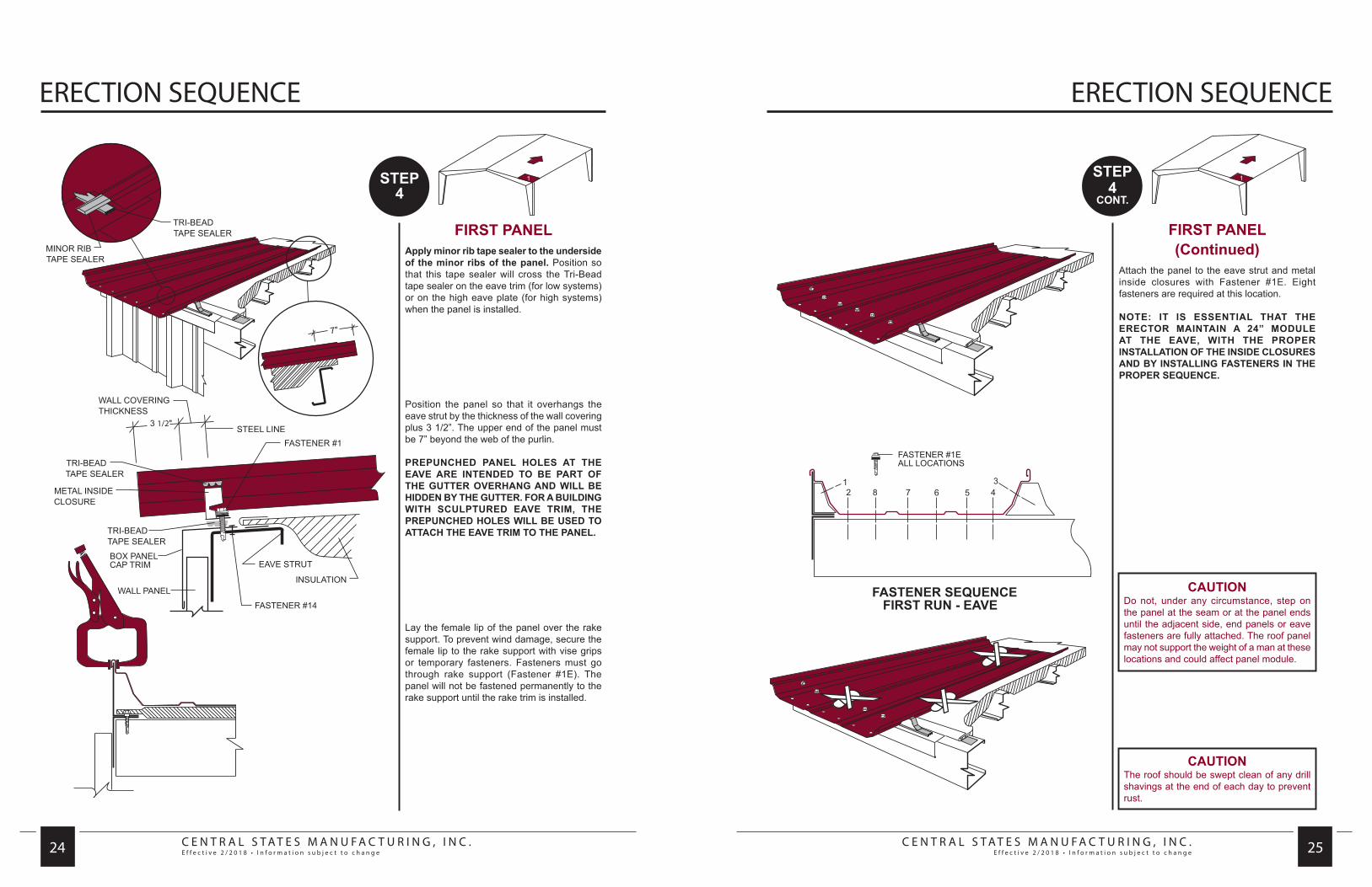
FIRST PANELApply minor rib tape sealer to the underside of the minor ribs of the panel. Position so that this tape sealer will cross the Tri-Bead tape sealer on the eave trim (for low systems) or on the high eave plate (for high systems) when the panel is installed.
Position the panel so that it overhangs the eave strut by the thickness of the wall covering plus 3 1/2”. The upper end of the panel must be 7” beyond the web of the purlin.
PREPUNCHED PANEL HOLES AT THE EAVE ARE INTENDED TO BE PART OF THE GUTTER OVERHANG AND WILL BE HIDDEN BY THE GUTTER. FOR A BUILDING WITH SCULPTURED EAVE TRIM, THE PREPUNCHED HOLES WILL BE USED TO ATTACH THE EAVE TRIM TO THE PANEL.
Lay the female lip of the panel over the rake support. To prevent wind damage, secure the female lip to the rake support with vise grips or temporary fasteners. Fasteners must go through rake support (Fastener #1E). The panel will not be fastened permanently to the rake support until the rake trim is installed.
FIRST PANEL(Continued)
Attach the panel to the eave strut and metal inside closures with Fastener #1E. Eight fasteners are required at this location.
NOTE: IT IS ESSENTIAL THAT THE ERECTOR MAINTAIN A 24” MODULE AT THE EAVE, WITH THE PROPER INSTALLATION OF THE INSIDE CLOSURES AND BY INSTALLING FASTENERS IN THE PROPER SEQUENCE.
CAUTIONDo not, under any circumstance, step on the panel at the seam or at the panel ends until the adjacent side, end panels or eave fasteners are fully attached. The roof panel may not support the weight of a man at these locations and could affect panel module.
CAUTIONThe roof should be swept clean of any drill shavings at the end of each day to prevent rust.
C E N T R A L S T A T E S M A N U F A C T U R I N G , I N C .E f f e c t i v e 2 / 2 0 1 8 • I n f o r m a t i o n s u b j e c t t o c h a n g e
C E N T R A L S T A T E S M A N U F A C T U R I N G , I N C .E f f e c t i v e 2 / 2 0 1 8 • I n f o r m a t i o n s u b j e c t t o c h a n g e 26 27
ERECTION SEQUENCEERECTION SEQUENCE
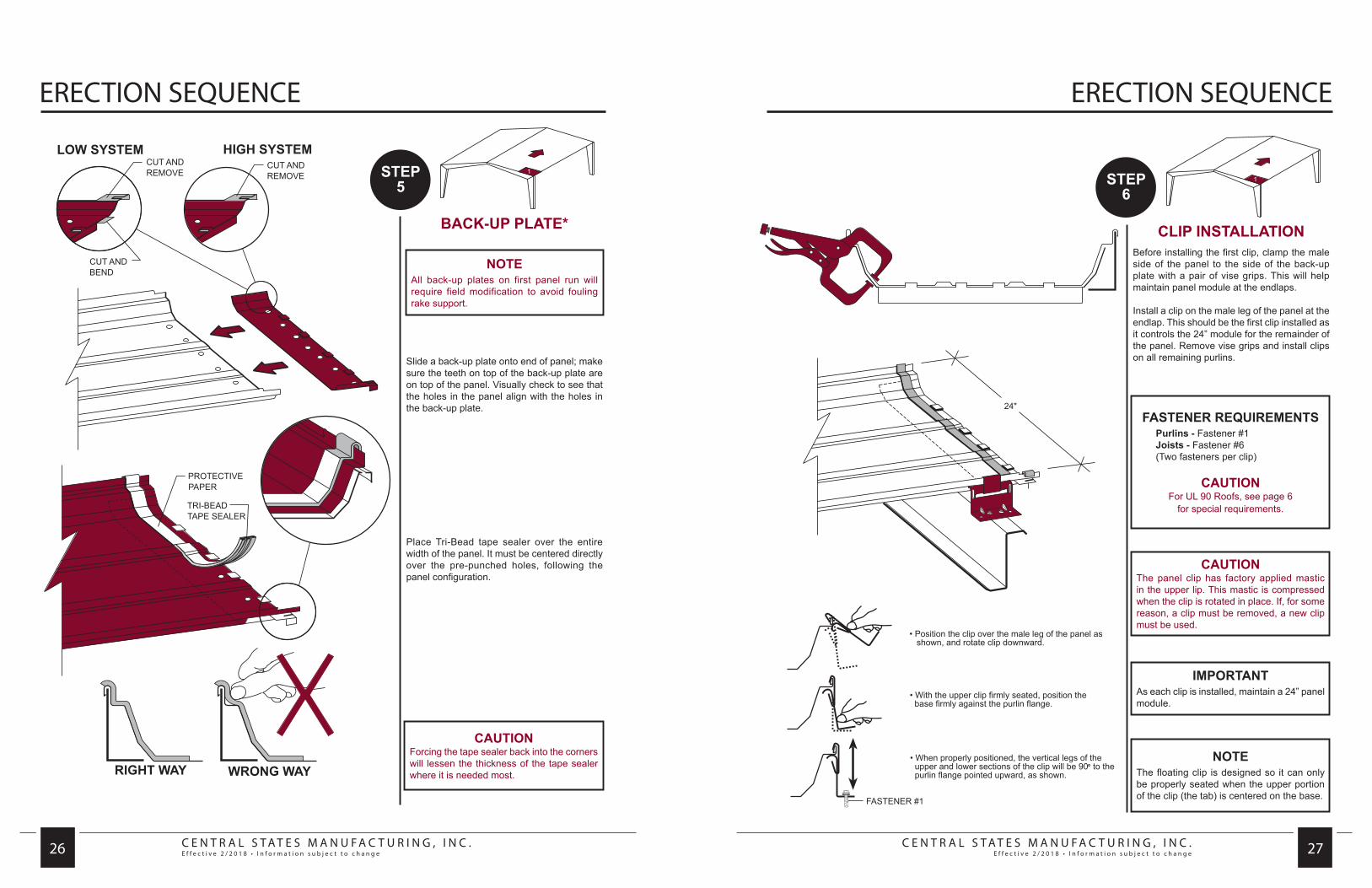
BACK-UP PLATE*
Slide a back-up plate onto end of panel; make sure the teeth on top of the back-up plate are on top of the panel. Visually check to see that the holes in the panel align with the holes in the back-up plate.
Place Tri-Bead tape sealer over the entire width of the panel. It must be centered directly over the pre-punched holes, following the panel configuration.
CAUTIONForcing the tape sealer back into the corners will lessen the thickness of the tape sealer where it is needed most.
NOTEAll back-up plates on first panel run will require field modification to avoid fouling rake support.
CLIP INSTALLATIONBefore installing the first clip, clamp the male side of the panel to the side of the back-up plate with a pair of vise grips. This will help maintain panel module at the endlaps.
Install a clip on the male leg of the panel at the endlap. This should be the first clip installed as it controls the 24” module for the remainder of the panel. Remove vise grips and install clips on all remaining purlins.
IMPORTANTAs each clip is installed, maintain a 24” panel module.
NOTEThe floating clip is designed so it can only be properly seated when the upper portion of the clip (the tab) is centered on the base.
CAUTIONThe panel clip has factory applied mastic in the upper lip. This mastic is compressed when the clip is rotated in place. If, for some reason, a clip must be removed, a new clip must be used.
FASTENER REQUIREMENTSPurlins - Fastener #1Joists - Fastener #6(Two fasteners per clip)
CAUTIONFor UL 90 Roofs, see page 6
for special requirements.

C E N T R A L S T A T E S M A N U F A C T U R I N G , I N C .E f f e c t i v e 2 / 2 0 1 8 • I n f o r m a t i o n s u b j e c t t o c h a n g e
C E N T R A L S T A T E S M A N U F A C T U R I N G , I N C .E f f e c t i v e 2 / 2 0 1 8 • I n f o r m a t i o n s u b j e c t t o c h a n g e 28 29
ERECTION SEQUENCEERECTION SEQUENCE
ENDLAP-PANEL
Position female lip of upper panel over rake support, while holding male side of panel up away from the tape sealer. Using an awl, align the hole nearest the female side of the top panel with the corresponding hole in the lower panel and the back-up plate.
Once this is accomplished, rotate the male side of the upper panel down to rest on the vise grips.
Make sure the panel notches are aligned.
Remove awl and insert in the middle hole nearest the male leg. Install Fastener #1E in the hole by the female leg.
CAUTIONThe roof should be swept clean of any drill shavings at the end of each day to prevent rust.
NOTEStep 7 applies only where more than one panel is used in a single slope.
STANDARD ENDLAP
All holes in the upper and lower panels and the back-up plate should now be aligned. Make sure that the panel notches are aligned.
Install Fastener #1E in sequence 2 and 3. Remove vise grips and install remaining fasteners in sequence 4, 5, 6.
Apply Tri-Bead tape sealer over the notched portion of these male legs.
Repeat the endlap procedures as required for each panel until the ridge or high eave is reached.
NOTEStep 8 applies only where more than one panel is used in a single slope.
C E N T R A L S T A T E S M A N U F A C T U R I N G , I N C .E f f e c t i v e 2 / 2 0 1 8 • I n f o r m a t i o n s u b j e c t t o c h a n g e
C E N T R A L S T A T E S M A N U F A C T U R I N G , I N C .E f f e c t i v e 2 / 2 0 1 8 • I n f o r m a t i o n s u b j e c t t o c h a n g e 30 31
ERECTION SEQUENCEERECTION SEQUENCE
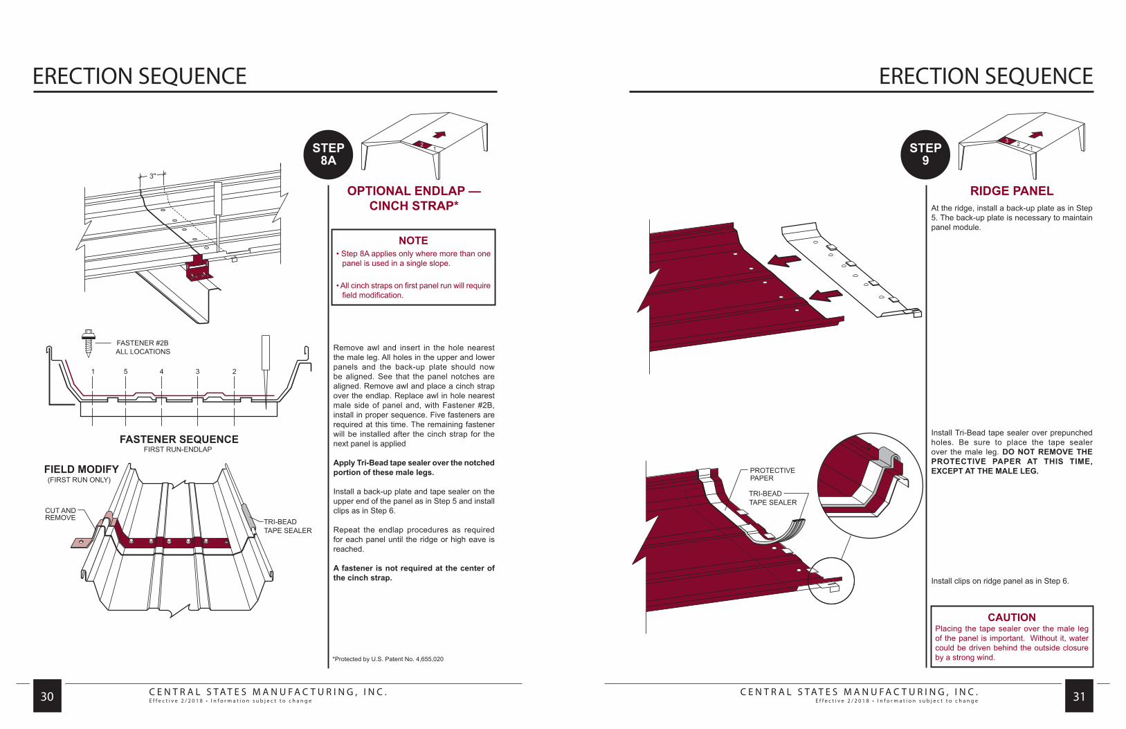
OPTIONAL ENDLAP — CINCH STRAP*
Remove awl and insert in the hole nearest the male leg. All holes in the upper and lower panels and the back-up plate should now be aligned. See that the panel notches are aligned. Remove awl and place a cinch strap over the endlap. Replace awl in hole nearest male side of panel and, with Fastener #2B, install in proper sequence. Five fasteners are required at this time. The remaining fastener will be installed after the cinch strap for the next panel is applied
Apply Tri-Bead tape sealer over the notched portion of these male legs.
Install a back-up plate and tape sealer on the upper end of the panel as in Step 5 and install clips as in Step 6.
Repeat the endlap procedures as required for each panel until the ridge or high eave is reached.
A fastener is not required at the center of the cinch strap.
*Protected by U.S. Patent No. 4,655,020
NOTE• Step 8A applies only where more than one
panel is used in a single slope.
• All cinch straps on first panel run will require field modification.
RIDGE PANELAt the ridge, install a back-up plate as in Step 5. The back-up plate is necessary to maintain panel module.
Install Tri-Bead tape sealer over prepunched holes. Be sure to place the tape sealer over the male leg. DO NOT REMOVE THE PROTECTIVE PAPER AT THIS TIME, EXCEPT AT THE MALE LEG.
Install clips on ridge panel as in Step 6.
CAUTIONPlacing the tape sealer over the male leg of the panel is important. Without it, water could be driven behind the outside closure by a strong wind.

C E N T R A L S T A T E S M A N U F A C T U R I N G , I N C .E f f e c t i v e 2 / 2 0 1 8 • I n f o r m a t i o n s u b j e c t t o c h a n g e
C E N T R A L S T A T E S M A N U F A C T U R I N G , I N C .E f f e c t i v e 2 / 2 0 1 8 • I n f o r m a t i o n s u b j e c t t o c h a n g e 32 33
ERECTION SEQUENCEERECTION SEQUENCE
CAUTIONNever use a hammer to force the panels to snap together. This will cause severe damage to the panel and will nullify any warranty.
CAUTIONIf a problem is encountered in fully snapping the seams together, such as an incorrectly installed clip, damaged panel lip, or a bubble caused by faulty assembly; the shaping tool should enable the seam to be locked with minimal effort.
SUBSEQUENT RUNS EAVEApply tape sealer to the male leg of the first panel run directly over the inside closure. This will prevent water infiltration through the end of the seam. Install the next run of insulation and another inside closure using Fastener #1. The second run of roof is now ready to install.
Position the panel with the female lip resting on top of the male leg. Align panel flush with adjacent panel. ONCE THE PANELS ARE SNAPPED TOGETHER, NO FURTHER ALIGNMENTS CAN BE MADE. Press down on the seam, snapping the two panels together. It is important to begin at one end of the panel and work to the other, applying pressure continuously all the way along the seam to avoid a bubble in the seam. Make certain the seams are fully locked together, particularly at the clips where greater resistance will be encountered.
Install fasteners at eave in the proper sequence. Eight fasteners are required at this location.
SUBSEQUENT RUNS ENDLAP
Install back-up plate and tape sealer as in Step 5. However, on this and all subsequent runs, care must be taken to engage the tab on the side into the slot of the adjacent back-up plate. This procedure will assist in maintaining a 24” panel module.
Install clips as described in Step 6.
Install upper panel as described in Steps 7 & 8.
Repeat the endlap procedures as required for each panel until the ridge is reached.
C E N T R A L S T A T E S M A N U F A C T U R I N G , I N C .E f f e c t i v e 2 / 2 0 1 8 • I n f o r m a t i o n s u b j e c t t o c h a n g e
C E N T R A L S T A T E S M A N U F A C T U R I N G , I N C .E f f e c t i v e 2 / 2 0 1 8 • I n f o r m a t i o n s u b j e c t t o c h a n g e 34 35
ERECTION SEQUENCEERECTION SEQUENCE
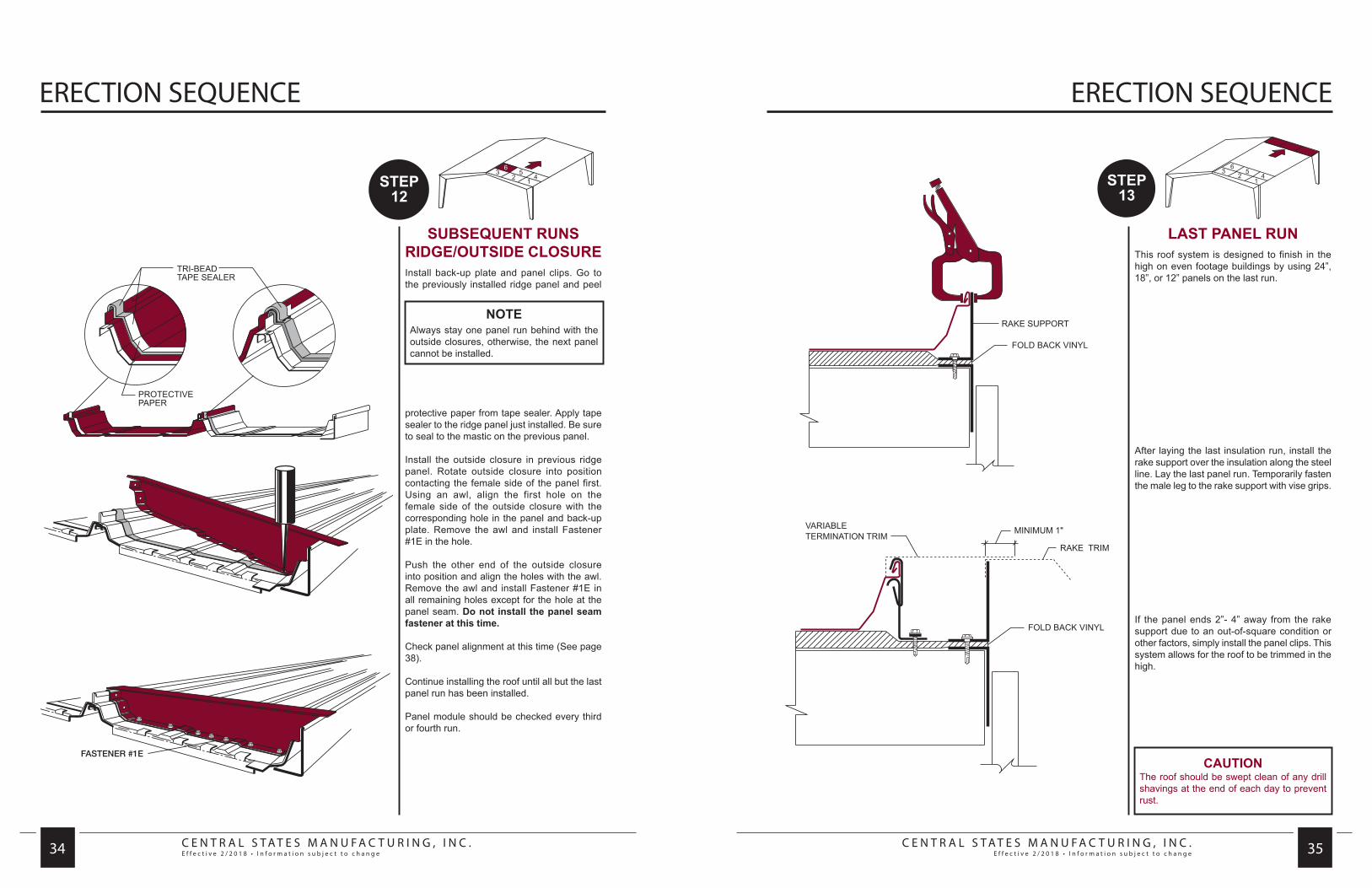
FASTENER #1E
SUBSEQUENT RUNS RIDGE/OUTSIDE CLOSUREInstall back-up plate and panel clips. Go to the previously installed ridge panel and peel
protective paper from tape sealer. Apply tape sealer to the ridge panel just installed. Be sure to seal to the mastic on the previous panel.
Install the outside closure in previous ridge panel. Rotate outside closure into position contacting the female side of the panel first. Using an awl, align the first hole on the female side of the outside closure with the corresponding hole in the panel and back-up plate. Remove the awl and install Fastener #1E in the hole.
Push the other end of the outside closure into position and align the holes with the awl. Remove the awl and install Fastener #1E in all remaining holes except for the hole at the panel seam. Do not install the panel seam fastener at this time.
Check panel alignment at this time (See page 38).
Continue installing the roof until all but the last panel run has been installed.
Panel module should be checked every third or fourth run.
NOTEAlways stay one panel run behind with the outside closures, otherwise, the next panel cannot be installed.
LAST PANEL RUNThis roof system is designed to finish in the high on even footage buildings by using 24”, 18”, or 12” panels on the last run.
After laying the last insulation run, install the rake support over the insulation along the steel line. Lay the last panel run. Temporarily fasten the male leg to the rake support with vise grips.
If the panel ends 2”- 4” away from the rake support due to an out-of-square condition or other factors, simply install the panel clips. This system allows for the roof to be trimmed in the high.
CAUTIONThe roof should be swept clean of any drill shavings at the end of each day to prevent rust.
C E N T R A L S T A T E S M A N U F A C T U R I N G , I N C .E f f e c t i v e 2 / 2 0 1 8 • I n f o r m a t i o n s u b j e c t t o c h a n g e
C E N T R A L S T A T E S M A N U F A C T U R I N G , I N C .E f f e c t i v e 2 / 2 0 1 8 • I n f o r m a t i o n s u b j e c t t o c h a n g e 36 37
ERECTION SEQUENCE ERECTION SEQUENCE
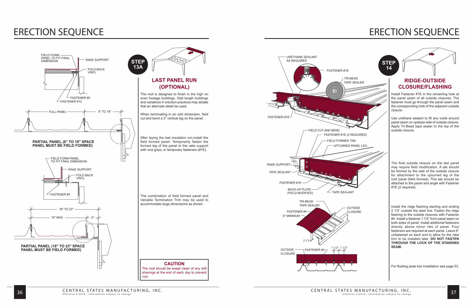
LAST PANEL RUN(OPTIONAL)
The roof is designed to finish in the high on even footage buildings. Odd length buildings and variations in erection practices may dictate that an alternate detail be used.
When terminating in an odd dimension, field cut and bend a 3” vertical leg on the panel.
After laying the last insulation run,install the field formed panel. Temporarily fasten the formed leg of the panel to the rake support with vice grips, or temporary fasteners (#1E).
The combination of field formed panel and Variable Termination Trim may be used to accommodate large dimensions as shown.
CAUTIONThe roof should be swept clean of any drill shavings at the end of each day to prevent rust.
RIDGE-OUTSIDE CLOSURE/FLASHING
Install Fastener #1E in the remaining hole at the panel seam of all outside closures. The fastener must go through the panel seam and the corresponding hole of the adjacent outside closure.
Use urethane sealant to fill any voids around panel seam on upslope side of outside closure. Apply Tri-Bead tape sealer to the top of the outside closure.
The final outside closure on the last panel may require field modification. A tab should be formed by the web of the outside closure for attachment to the upturned leg of the roof panel (field formed). This tab should be attached to the panel and angle with Fastener #1E (2 required).
Install the ridge flashing starting and ending 2 1/2” outside the steel line. Fasten the ridge flashing to the outside closures with Fastener #4. Install a fastener 1 1/2” from panel seam on both sides of panel. Install additional fasteners directly above minor ribs of panel. Four fasteners are required at each panel. Leave 6” unfastened on each end to allow for the rake trim to be installed later. DO NOT FASTEN THROUGH THE LOCK OF THE STANDING SEAM.
For floating peak box installation see page 53.

C E N T R A L S T A T E S M A N U F A C T U R I N G , I N C .E f f e c t i v e 2 / 2 0 1 8 • I n f o r m a t i o n s u b j e c t t o c h a n g e
C E N T R A L S T A T E S M A N U F A C T U R I N G , I N C .E f f e c t i v e 2 / 2 0 1 8 • I n f o r m a t i o n s u b j e c t t o c h a n g e 38 39
SPECIAL ERECTION TECHNIQUES SPECIAL ERECTION TECHNIQUES
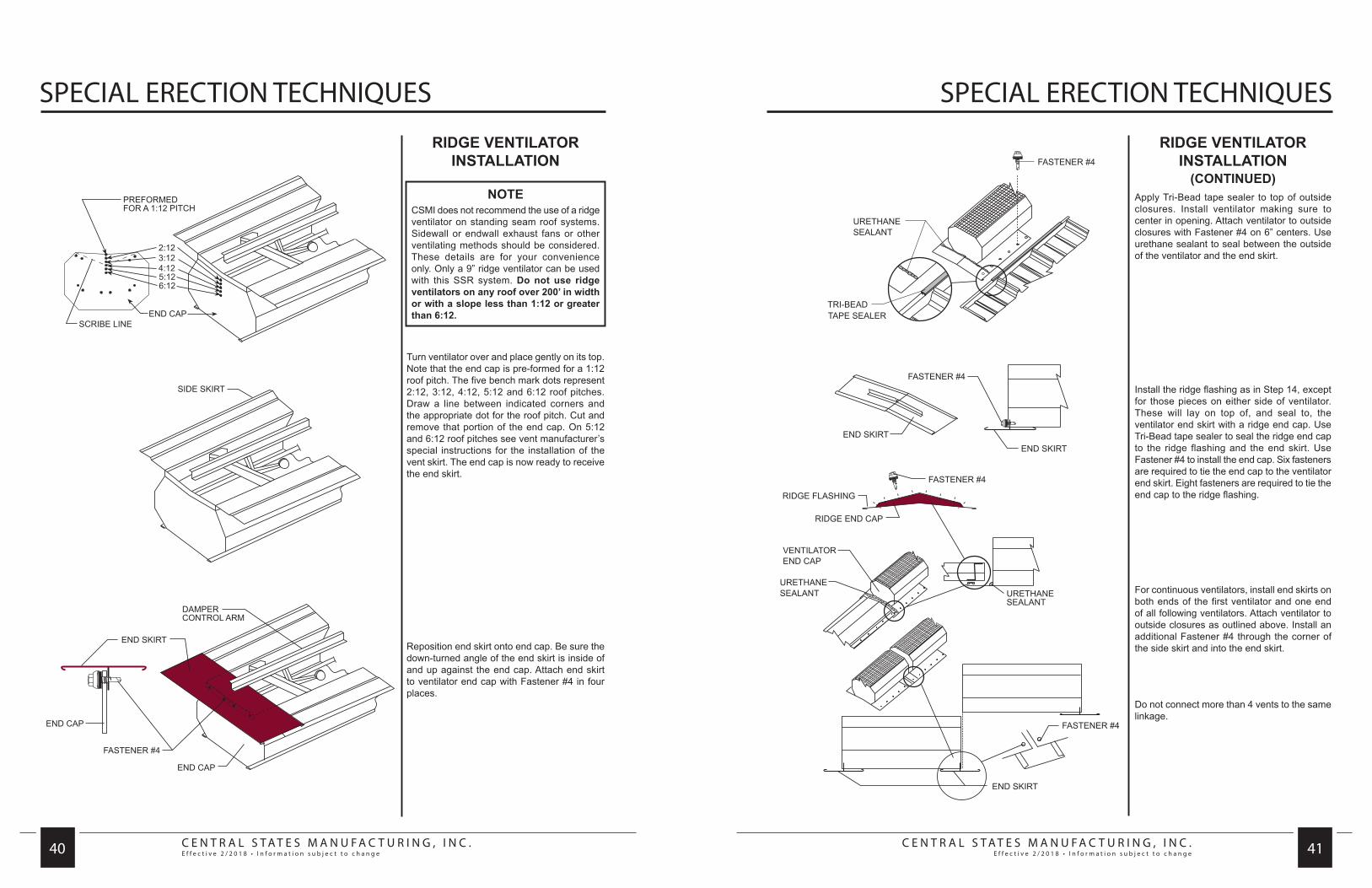
RECOMMENDED ERECTION PRACTICES
CORRECTING OUT-OF-PLANE SUBSTRUCTURE
Occasionally a purlin may be encountered that is lower (out-of-plane) than those adjacent to it. When a clip is attached to this purlin, it will go down further than those adjacent to it, distorting the seam. This can cause the next panel sidelap to be difficult to snap together in this area. To compensate for this lower purlin, a steel shim may be placed under the clip to bring it up to the proper height (in plane). This shim should be no thicker than 1/4”. If 1/4” is not enough, then structural modification will be necessary.
Avoid “stair-stepping” of the panels at the eave. This will cause problems engaging back-up plates at the endlap and ridge. This also will create the need to warp the cinch strap (if used) over the high rib forcing it to align with the holes in the adjacent panel.
Any “stripped out” fasteners at the endlaps or outside closures should be immediately replaced with Fastener #2A. Place a 1” long piece of Tri-bead tape sealer over the “stripped out” hole before installing Fastener #2A. This will allow the fastener threads to be coated with tape sealer and provide a good seal.
NEVER ALLOW PANELS TO COME INTO CONTACT WITH LEAD, COPPER, GRAPHITE, GASOLINE OR OTHER HARSH CHEMICALS AS THIS WILL VOID THE GALVALUME WARRANTY.
CHECK ROOF FOR PANEL ALIGNMENT
Check the roof every three or four runs for panel alignment as it is being erected. This can be accomplished by two different means.
1. Measure from the rake support to the seam of the last completed panel run. Take measurements at the ridge, eave, and all endlaps.
2. Attach a stringline to the eave plate and ridge purlin, running parallel to the rake support. The stringline should stay ahead of the work and can be moved across the roof as construction progresses. Measure from the stringline back to the last completed panel run. Take measurements at the ridge, eave, and all endlaps.
RECOMMENDED ERECTION PRACTICES
(CONTINUED)ADJUSTING PANEL WIDTH
SLIDING CLIP ONLYTo stretch panel coverage, install an articulating clip at the panel endlap or ridge with the base angled away from the panel. As the fastener is installed through the base of the clip and into the purlin, the clip base will rotate down to the purlin causing the top of the clip to move outward, stretching the panel coverage. Install the remainder of the clips as usual.
To shrink panel coverage, install an articulating clip at the panel endlap or ridge with the base angled toward the panel. As the fastener is installed through the base of the clip and into the purlin, the clip base will rotate down to the purlin causing the top of the clip to move inward, shrinking panel coverage. Install the remainder of the clips as usual.
FIXED AND FLOATING CLIPSTo stretch panel coverage, bend the sides of the back-up plate out and install at endlap or ridge. Do not bend either side more than 1/4”. Install clips as usual.
To shrink panel coverage, bend the sides of the back-up plate in and install at endlap or ridge. Do not bend either side more than 1/4”. Install clips as usual.
NOTEDo not adjust panel width more than 1/2” on any panel area.
C E N T R A L S T A T E S M A N U F A C T U R I N G , I N C .E f f e c t i v e 2 / 2 0 1 8 • I n f o r m a t i o n s u b j e c t t o c h a n g e
C E N T R A L S T A T E S M A N U F A C T U R I N G , I N C .E f f e c t i v e 2 / 2 0 1 8 • I n f o r m a t i o n s u b j e c t t o c h a n g e 40 41
SPECIAL ERECTION TECHNIQUES SPECIAL ERECTION TECHNIQUES
RIDGE VENTILATOR INSTALLATION
Turn ventilator over and place gently on its top. Note that the end cap is pre-formed for a 1:12 roof pitch. The five bench mark dots represent 2:12, 3:12, 4:12, 5:12 and 6:12 roof pitches. Draw a line between indicated corners and the appropriate dot for the roof pitch. Cut and remove that portion of the end cap. On 5:12 and 6:12 roof pitches see vent manufacturer’s special instructions for the installation of the vent skirt. The end cap is now ready to receive the end skirt.
Reposition end skirt onto end cap. Be sure the down-turned angle of the end skirt is inside of and up against the end cap. Attach end skirt to ventilator end cap with Fastener #4 in four places.
NOTECSMI does not recommend the use of a ridge ventilator on standing seam roof systems. Sidewall or endwall exhaust fans or other ventilating methods should be considered. These details are for your convenience only. Only a 9” ridge ventilator can be used with this SSR system. Do not use ridge ventilators on any roof over 200’ in width or with a slope less than 1:12 or greater than 6:12.
RIDGE VENTILATOR INSTALLATION
(CONTINUED)Apply Tri-Bead tape sealer to top of outside closures. Install ventilator making sure to center in opening. Attach ventilator to outside closures with Fastener #4 on 6” centers. Use urethane sealant to seal between the outside of the ventilator and the end skirt.
Install the ridge flashing as in Step 14, except for those pieces on either side of ventilator. These will lay on top of, and seal to, the ventilator end skirt with a ridge end cap. Use Tri-Bead tape sealer to seal the ridge end cap to the ridge flashing and the end skirt. Use Fastener #4 to install the end cap. Six fasteners are required to tie the end cap to the ventilator end skirt. Eight fasteners are required to tie the end cap to the ridge flashing.
For continuous ventilators, install end skirts on both ends of the first ventilator and one end of all following ventilators. Attach ventilator to outside closures as outlined above. Install an additional Fastener #4 through the corner of the side skirt and into the end skirt.
Do not connect more than 4 vents to the same linkage.
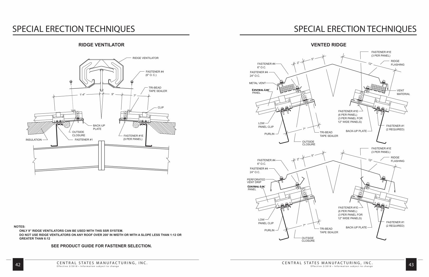
C E N T R A L S T A T E S M A N U F A C T U R I N G , I N C .E f f e c t i v e 2 / 2 0 1 8 • I n f o r m a t i o n s u b j e c t t o c h a n g e
C E N T R A L S T A T E S M A N U F A C T U R I N G , I N C .E f f e c t i v e 2 / 2 0 1 8 • I n f o r m a t i o n s u b j e c t t o c h a n g e 42 43
SPECIAL ERECTION TECHNIQUES SPECIAL ERECTION TECHNIQUES
RIDGE VENTILATOR
NOTES: ONLY 9” RIDGE VENTILATORS CAN BE USED WITH THIS SSR SYSTEM. DO NOT USE RIDGE VENTILATORS ON ANY ROOF OVER 200’ IN WIDTH OR WITH A SLOPE LESS THAN 1:12 OR
GREATER THAN 6:12
SEE PRODUCT GUIDE FOR FASTENER SELECTION.
VENTED RIDGE

C E N T R A L S T A T E S M A N U F A C T U R I N G , I N C .E f f e c t i v e 2 / 2 0 1 8 • I n f o r m a t i o n s u b j e c t t o c h a n g e
C E N T R A L S T A T E S M A N U F A C T U R I N G , I N C .E f f e c t i v e 2 / 2 0 1 8 • I n f o r m a t i o n s u b j e c t t o c h a n g e 44 45
SPECIAL ERECTION TECHNIQUES SPECIAL ERECTION TECHNIQUES
NOTES: 1. This special detail is for use when a panel run exceeds the thermal movement capabilities of the panel clip. Please refer
to page 5. 2. A positive panel attachment is made at the mid-point in the panel run allowing for thermal movement to the eave and
ridge. 3. The standard floating ridge condition must be used in conjunction with this special eave detail. 4. The floating eave plate must be used to allow for panel movement at the eave. 5. Floating clips have a maximum movement of 1” in each direction. Articulating clips have a maximum movement of 1 1/4”
in each direction. Thermal calculations must be performed for each project to ensure that the thermal movement of the roof will not exceed the design of the clips and slot in the floating eave plate.
MID SLOPE FIXEDCONDITION
ROOF CURB INSTALLATION
CSMI recommends that only one-piece aluminum curbs, such as those manufactured by LM Curb (800-284-1412) be used on its standing seam roof systems. The curb flange is constructed to match the configuration of the panel. The side flanges extend to the next natural seam in the roof panels and conform to the seam configuration. Cap strips, furnished by the curb manufacturer, secure the curb to the roof panels. The roof curb is installed under the roof panels on the upslope end and on top of the roof panels on the downslope end. Support framing should be supplied by the curb manufacturer. Back-up plates (for the roof panels at the down slope end of the curb), long-life fasteners and Triple Bead tape sealer must be ordered for each curb.These curbs may be installed as the roof is being installed or after the roof has been installed. Since the curb sides are an integral part of the roof seam, the curb must align with the roof panel seams. If the curb can be shifted up to 12” to either side, the curb can be pre-ordered and be installed with the roof panels or installed after the roof is in place. If the curb placement is critical, install the curb support framing at the desired location and roof over it. Measure the panel rib locations in reference to the required curb opening and order the roof curb for each location. The curbs can then be installed in each location, ensuring an exact fit.
INSTALLING CURB WITH ROOFInstall curb support framing at curb location. Install full length roof panels up to curb location. Install lower panels at downslope end of curb. If the lower panels are field cut to length, you must (1) cut the downslope end, leaving a factory cut at the curb end or (2) if the curb end of the panel is field cut, notch the male leg as it is done in the factory. Place Triple Bead tape sealer across the full width of each panel as it is installed. To determine how far down on the panel to place the tape sealer, temporarily lay the curb in place and mark the down slope edge of the curb on the first panel. This will give you a reference point as to how far down slope to place the tape sealer. It is critical that the tape sealer be installed across each panel individually so that the tape sealer can be placed over the male leg. This will provide a seal in the panel seam when the next panel is installed. Install back-up plates onto each of the lower panels.
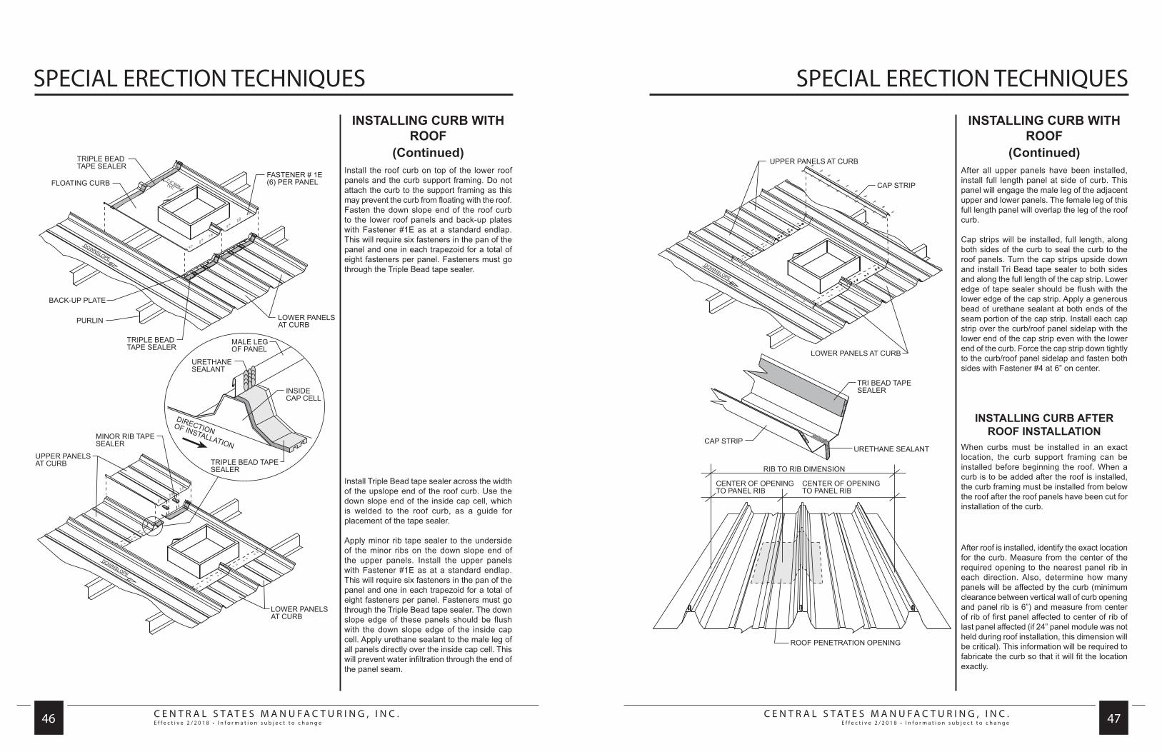
C E N T R A L S T A T E S M A N U F A C T U R I N G , I N C .E f f e c t i v e 2 / 2 0 1 8 • I n f o r m a t i o n s u b j e c t t o c h a n g e
C E N T R A L S T A T E S M A N U F A C T U R I N G , I N C .E f f e c t i v e 2 / 2 0 1 8 • I n f o r m a t i o n s u b j e c t t o c h a n g e 46 47
SPECIAL ERECTION TECHNIQUES SPECIAL ERECTION TECHNIQUES
INSTALLING CURB WITH ROOF
(Continued)Install the roof curb on top of the lower roof panels and the curb support framing. Do not attach the curb to the support framing as this may prevent the curb from floating with the roof. Fasten the down slope end of the roof curb to the lower roof panels and back-up plates with Fastener #1E as at a standard endlap. This will require six fasteners in the pan of the panel and one in each trapezoid for a total of eight fasteners per panel. Fasteners must go through the Triple Bead tape sealer.
Install Triple Bead tape sealer across the width of the upslope end of the roof curb. Use the down slope end of the inside cap cell, which is welded to the roof curb, as a guide for placement of the tape sealer.
Apply minor rib tape sealer to the underside of the minor ribs on the down slope end of the upper panels. Install the upper panels with Fastener #1E as at a standard endlap. This will require six fasteners in the pan of the panel and one in each trapezoid for a total of eight fasteners per panel. Fasteners must go through the Triple Bead tape sealer. The down slope edge of these panels should be flush with the down slope edge of the inside cap cell. Apply urethane sealant to the male leg of all panels directly over the inside cap cell. This will prevent water infiltration through the end of the panel seam.
INSTALLING CURB WITH ROOF
(Continued)After all upper panels have been installed, install full length panel at side of curb. This panel will engage the male leg of the adjacent upper and lower panels. The female leg of this full length panel will overlap the leg of the roof curb.
Cap strips will be installed, full length, along both sides of the curb to seal the curb to the roof panels. Turn the cap strips upside down and install Tri Bead tape sealer to both sides and along the full length of the cap strip. Lower edge of tape sealer should be flush with the lower edge of the cap strip. Apply a generous bead of urethane sealant at both ends of the seam portion of the cap strip. Install each cap strip over the curb/roof panel sidelap with the lower end of the cap strip even with the lower end of the curb. Force the cap strip down tightly to the curb/roof panel sidelap and fasten both sides with Fastener #4 at 6” on center.
INSTALLING CURB AFTER ROOF INSTALLATION
When curbs must be installed in an exact location, the curb support framing can be installed before beginning the roof. When a curb is to be added after the roof is installed, the curb framing must be installed from below the roof after the roof panels have been cut for installation of the curb.
After roof is installed, identify the exact location for the curb. Measure from the center of the required opening to the nearest panel rib in each direction. Also, determine how many panels will be affected by the curb (minimum clearance between vertical wall of curb opening and panel rib is 6”) and measure from center of rib of first panel affected to center of rib of last panel affected (if 24” panel module was not held during roof installation, this dimension will be critical). This information will be required to fabricate the curb so that it will fit the location exactly.

C E N T R A L S T A T E S M A N U F A C T U R I N G , I N C .E f f e c t i v e 2 / 2 0 1 8 • I n f o r m a t i o n s u b j e c t t o c h a n g e
C E N T R A L S T A T E S M A N U F A C T U R I N G , I N C .E f f e c t i v e 2 / 2 0 1 8 • I n f o r m a t i o n s u b j e c t t o c h a n g e 48 49
SPECIAL ERECTION TECHNIQUES SPECIAL ERECTION TECHNIQUES
INSTALLING CURB AFTER ROOF
(Continued)Once curb is ready to be installed, lay curb on roof and align opening in the curb with the exact location the opening is required in the roof. At the up slope end of the roof curb, the roof panels will be cut on a line even with the beginning of the notch at the vertical leg on each side of the roof curb. Secondly, trace a line along the down slope edge of the roof curb. The roof panels will be cut on a line 4” up slope from this line.
Cut roof panels from rib of first panel affected by curb, to rib of last panel affected, along the top and bottom cut lines previously marked.
At the down slope end of the roof opening, install back-up plates onto the ends of the cut roof panels and Triple Bead tape sealer across the full width of these roof panels. The down slope edge of the tape sealer should be on the line previously traced along the downslope edge of the roof curb. The up slope edge of the tape sealer will be approximately 1-1/2” from the end of the cut panel.
Apply Triple Bead tape sealer across the full width of the up slope end of the roof curb. The down slope edge of the tape sealer will align with the down slope edge of the inside cap cells welded to the roof curb.
Install the roof curb under the roof panels at the up slope end and on top of the panels at the down slope end. This will require that you lift the roof panels up slightly at the up slope end to allow the upper flange of the roof curb to slide under the panels. Spray some soapy water on the tape sealer to prevent it from sticking to the roof panels until you have the curb completely in place.
INSTALLING CURB AFTER ROOF
(Continued)Cap strips will be installed, full length along both sides of the curb to seal the curb to the roof panels. Turn the cap strips upside down and install Tri Bead tape sealer to both sides and along the full length of the cap strip. Lower edge of tape sealer should be flush with the lower edge of the cap strip. Apply a generous bead of urethane sealant at both ends of the seam portion of the cap strip. Install each cap strip over the curb/roof panel sidelap with the lower end of the cap strip even with the lower end of the curb. Force the cap strip down tightly to the curb/roof panel sidelap and fasten both sides with Fastener #4 at 6” on center.

C E N T R A L S T A T E S M A N U F A C T U R I N G , I N C .E f f e c t i v e 2 / 2 0 1 8 • I n f o r m a t i o n s u b j e c t t o c h a n g e
C E N T R A L S T A T E S M A N U F A C T U R I N G , I N C .E f f e c t i v e 2 / 2 0 1 8 • I n f o r m a t i o n s u b j e c t t o c h a n g e 50 51
SPECIAL ERECTION TECHNIQUES DESIGN
ROOF CURBCROSS SECTION
1. Panel
2. Urethane Sealant
3. Outside Cap Cell
4. Back-up Plate
5. Fastener #1E
6. Triple Bead Tape Sealer
7. Roof Curb
8. Water Diverter
9. Inside Cap Cell
Curbs can be ordered from LM Curbs at1-800-284-1412.
NOTE: THE ABOVE GUTTER SHOULD NOT BE USED IN AREAS THAT EXPERIENCE SNOW LOADS OF 10 PSF OR HIGHER. SEE PAGE 59 FOR THE GUTTER DETAIL FOR THESE AREAS.
SEE PRODUCT GUIDE FOR FASTENER SELECTION.
TRIM DETAILSEAVE TO ENDLAP
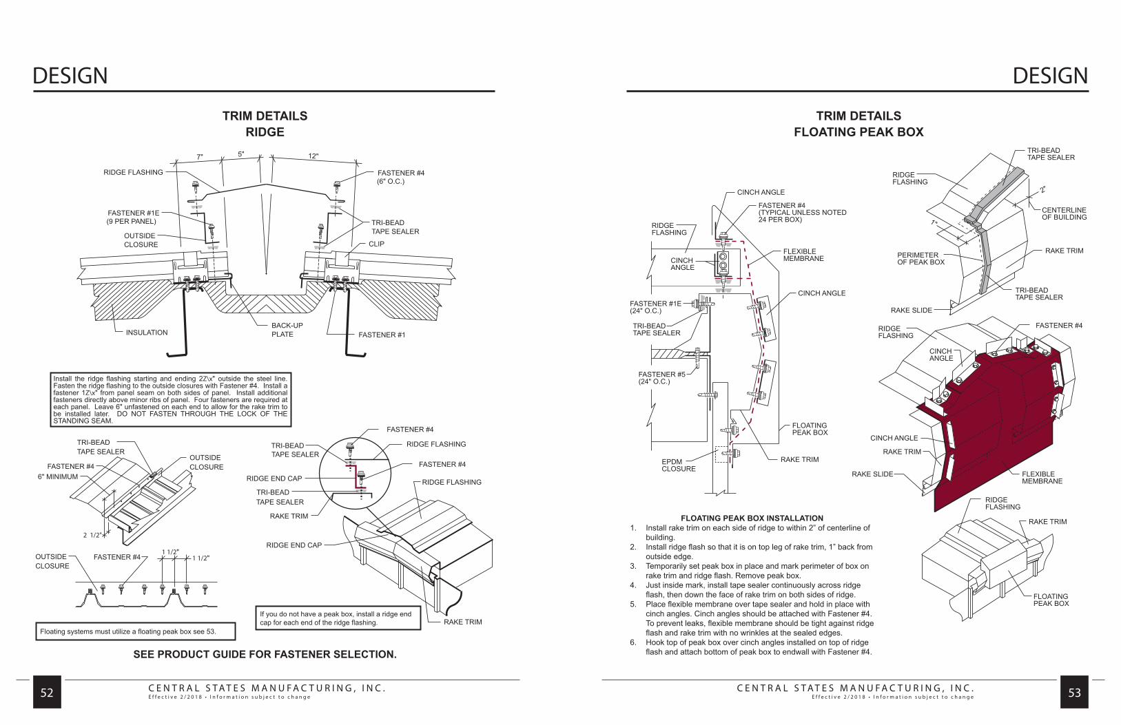
C E N T R A L S T A T E S M A N U F A C T U R I N G , I N C .E f f e c t i v e 2 / 2 0 1 8 • I n f o r m a t i o n s u b j e c t t o c h a n g e
C E N T R A L S T A T E S M A N U F A C T U R I N G , I N C .E f f e c t i v e 2 / 2 0 1 8 • I n f o r m a t i o n s u b j e c t t o c h a n g e 52 53
DESIGN DESIGN
TRIM DETAILSRIDGE
SEE PRODUCT GUIDE FOR FASTENER SELECTION.
Floating systems must utilize a floating peak box see 53.
If you do not have a peak box, install a ridge end cap for each end of the ridge flashing.
TRIM DETAILSFLOATING PEAK BOX
FLOATING PEAK BOX INSTALLATION1. Install rake trim on each side of ridge to within 2” of centerline of
building.2. Install ridge flash so that it is on top leg of rake trim, 1” back from
outside edge.3. Temporarily set peak box in place and mark perimeter of box on
rake trim and ridge flash. Remove peak box.4. Just inside mark, install tape sealer continuously across ridge
flash, then down the face of rake trim on both sides of ridge.5. Place flexible membrane over tape sealer and hold in place with
cinch angles. Cinch angles should be attached with Fastener #4. To prevent leaks, flexible membrane should be tight against ridge flash and rake trim with no wrinkles at the sealed edges.
6. Hook top of peak box over cinch angles installed on top of ridge flash and attach bottom of peak box to endwall with Fastener #4.
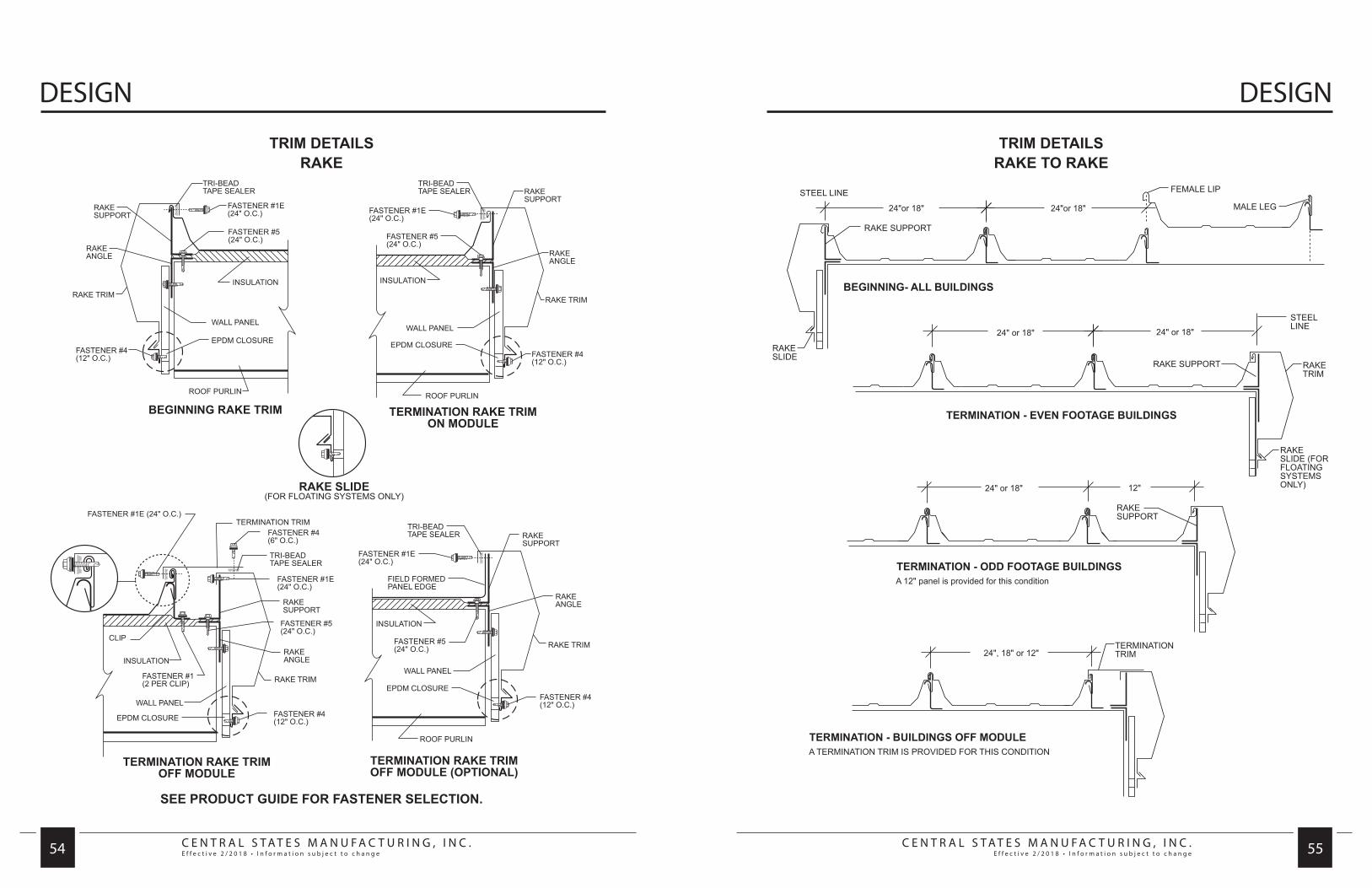
C E N T R A L S T A T E S M A N U F A C T U R I N G , I N C .E f f e c t i v e 2 / 2 0 1 8 • I n f o r m a t i o n s u b j e c t t o c h a n g e
C E N T R A L S T A T E S M A N U F A C T U R I N G , I N C .E f f e c t i v e 2 / 2 0 1 8 • I n f o r m a t i o n s u b j e c t t o c h a n g e 54 55
DESIGN DESIGN
SEE PRODUCT GUIDE FOR FASTENER SELECTION.
TRIM DETAILSRAKE
TRIM DETAILSRAKE TO RAKE
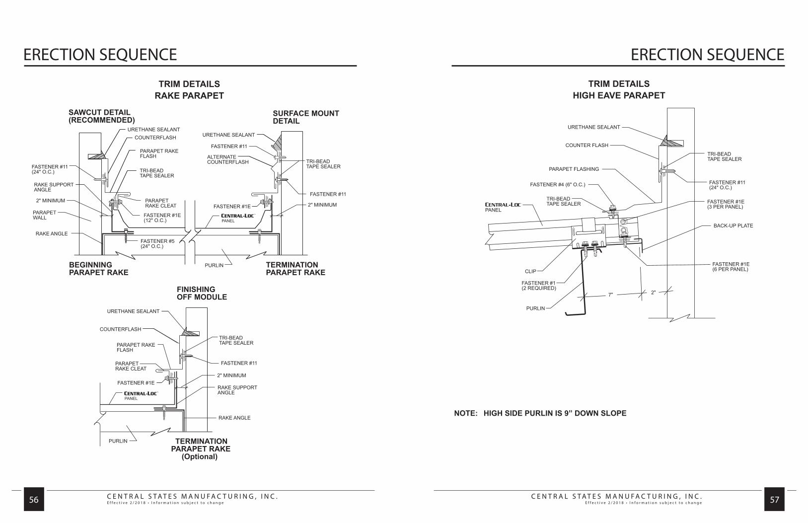
C E N T R A L S T A T E S M A N U F A C T U R I N G , I N C .E f f e c t i v e 2 / 2 0 1 8 • I n f o r m a t i o n s u b j e c t t o c h a n g e
C E N T R A L S T A T E S M A N U F A C T U R I N G , I N C .E f f e c t i v e 2 / 2 0 1 8 • I n f o r m a t i o n s u b j e c t t o c h a n g e 56 57
ERECTION SEQUENCE ERECTION SEQUENCE
TRIM DETAILSRAKE PARAPET
TRIM DETAILSHIGH EAVE PARAPET
NOTE: HIGH SIDE PURLIN IS 9” DOWN SLOPE

C E N T R A L S T A T E S M A N U F A C T U R I N G , I N C .E f f e c t i v e 2 / 2 0 1 8 • I n f o r m a t i o n s u b j e c t t o c h a n g e
C E N T R A L S T A T E S M A N U F A C T U R I N G , I N C .E f f e c t i v e 2 / 2 0 1 8 • I n f o r m a t i o n s u b j e c t t o c h a n g e 58 59
DESIGN DESIGN
TRIM DETAILSEAVE
NOTE: THIS OPTIONAL SCULPTURED EAVE TRIM IS AVAILABLE. HOWEVER, UNDER CERTAIN CONDITIONS IT MAY INDUCE STAINING OF WALL PANELS.
TRIM DETAILSSNOW GUTTER
NOTES: 1. Attach gutter to eave plate with Fastener #14A (3 fasteners per 10’ piece). 2. Install gutter straps 3’-0” O.C. 3. Apply Tri-Bead tape sealer to slope leg of gutter. 4. Use minor rib tape sealer to fill voids in panel at minor ribs as shown on page 35. 5. Install panel with Fastener #1E at prepunched holes. Panel must not overhang into gutter. 6. Front top edge of gutter must not project above the plane of the panel pan. 7. Snow gutter is non-standard.
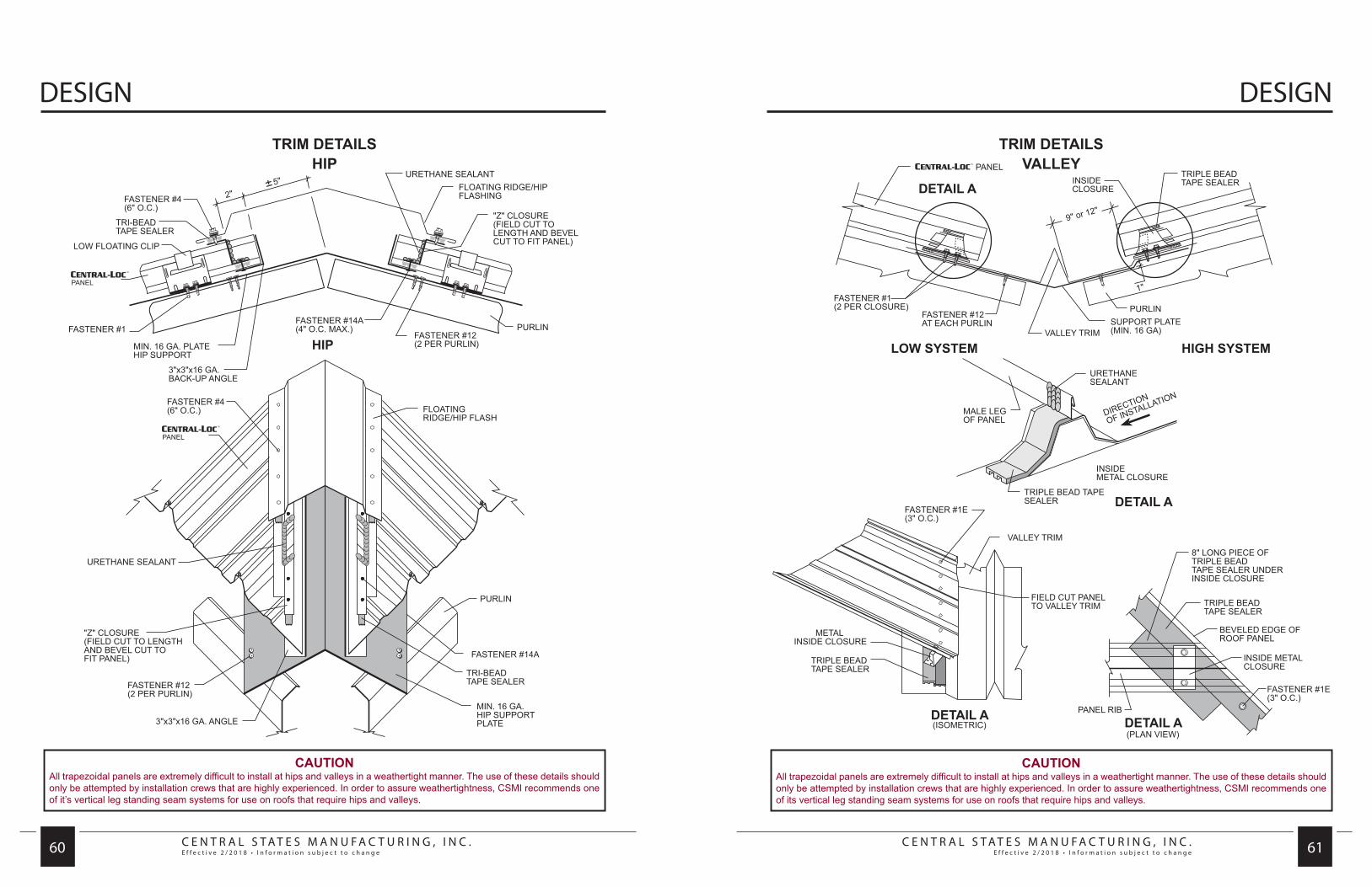
C E N T R A L S T A T E S M A N U F A C T U R I N G , I N C .E f f e c t i v e 2 / 2 0 1 8 • I n f o r m a t i o n s u b j e c t t o c h a n g e
C E N T R A L S T A T E S M A N U F A C T U R I N G , I N C .E f f e c t i v e 2 / 2 0 1 8 • I n f o r m a t i o n s u b j e c t t o c h a n g e 60 61
DESIGN DESIGN
TRIM DETAILSHIP
CAUTIONAll trapezoidal panels are extremely difficult to install at hips and valleys in a weathertight manner. The use of these details should only be attempted by installation crews that are highly experienced. In order to assure weathertightness, CSMI recommends one of it’s vertical leg standing seam systems for use on roofs that require hips and valleys.
TRIM DETAILSVALLEY
CAUTIONAll trapezoidal panels are extremely difficult to install at hips and valleys in a weathertight manner. The use of these details should only be attempted by installation crews that are highly experienced. In order to assure weathertightness, CSMI recommends one of its vertical leg standing seam systems for use on roofs that require hips and valleys.

C E N T R A L S T A T E S M A N U F A C T U R I N G , I N C .E f f e c t i v e 2 / 2 0 1 8 • I n f o r m a t i o n s u b j e c t t o c h a n g e 62
NOTES

w w w.CentralStatesMfg.com