centrifuge modeling of batter pile foundations under
TRANSCRIPT

HAL Id: hal-01300250https://hal.archives-ouvertes.fr/hal-01300250
Submitted on 11 Nov 2019
HAL is a multi-disciplinary open accessarchive for the deposit and dissemination of sci-entific research documents, whether they are pub-lished or not. The documents may come fromteaching and research institutions in France orabroad, or from public or private research centers.
L’archive ouverte pluridisciplinaire HAL, estdestinée au dépôt et à la diffusion de documentsscientifiques de niveau recherche, publiés ou non,émanant des établissements d’enseignement et derecherche français ou étrangers, des laboratoirespublics ou privés.
Centrifuge modeling of batter pile foundations undersinusoidal dynamic excitation
Zheng Li, Sandra Escoffier, Panagiotis Kotronis
To cite this version:Zheng Li, Sandra Escoffier, Panagiotis Kotronis. Centrifuge modeling of batter pile foundations undersinusoidal dynamic excitation. Bulletin of Earthquake Engineering, Springer Verlag, 2016, 14 (3),pp.673-697. �10.1007/s10518-015-9859-2�. �hal-01300250�

n CorrE-m
sandra.ePanagio
Centrifuge modeling of batter pile foundations under earthquakeexcitation
Zheng Li a,b,n, Sandra Escoffier a, Panagiotis Kotronis b
a IFSTTAR, GERS, SV, F-44341 Bouguenais, Franceb Ecole Centrale de Nantes, Université de Nantes, CNRS, Institut de Recherche en Génie Civil et Mécanique (GeM), 1 Rue de la Noë, F-44321 Nantes, France
dely usderstounderesentedrstructupile c
l bendil role onot onlytype ofase to b
Although batter pile foundations are wiseismic loadings is not yet thoroughly unthe behavior of batter and vertical pilesmental dynamic centrifuge program is prheight of the gravity center of the supelyzed (displacement and rotation of themoment, residual bending moment, totacertain cases batter piles play a beneficiaperformance of batter piles depends ncontent and amplitude) but also on thework provides a new experimental databin seismic regions.
esponding author at: IFSTTAR, GERS, SV, F-44ail addresses: [email protected], [email protected] (S. Escoffier),[email protected] (P. Kotronis).
ed in civil engineering structures, their behavior underod. This paper provides insights about the differences inseismic soil-pile-superstructure interaction. An experi-, where the influences of the base shaking signal and there are investigated. Various seismic responses are ana-ap, total shear force at the pile cap level, overturningng moment and axial forces in piles). It is found that inthe seismic behavior of the pile foundation system. Theon the characteristics of the earthquakes (frequencysuperstructures they support. This novel experimentaletter understand the behavior of batter pile foundations
1. Introduction
Batter piles, also called inclined or raked piles, are widely usedin civil engineering constructions where substantial lateral re-sistance is required. However, many building codes or standardslike AFPS 1990 [1] and Eurocode-8 [2] do not recommend the useof batter piles in seismic regions. Although less conservative, codeslike ACI318-05 and ACI318-11 recommend to pay attention to thepotential damages at the junction of the batter piles and the su-perstructure. The main drawbacks of the batter piles often men-tioned by engineers are the following: large forces induced ontothe pile cap, reduction in bending capacity due to the axial forces,unfavorable rotation on the cap and residual bending moment dueto the soil settlement before the earthquake [3]. Several case his-tories, for example, the wharf failure in the port of Oakland in 1989during the Loma Prieta earthquake and the port of Los Angeles in1994 during the Northridge earthquake reveal the unsatisfactoryperformance of batter piles.
However, recent studies show that batter piles can have a po-sitive performance. As reported by Gazetas and Mylonakis [4],batter piles, if properly designed, can play a beneficial role both for
341 Bouguenais, [email protected] (Z. Li),
1
the structure they support and the piles themselves (reduction ofthe bending moments in the piles). Research studies from Pender[5] and Berrill et al. [6] also suggest important beneficial effectsfrom batter piles. The argument about whether the use of batterpiles in seismic regions is detrimental or beneficial is therefore stillunsettled. In 2004, Harn [7] pointed out that the poor performanceof batter piles in past earthquakes may due to the lack of knowl-edge and analytical tools. Using displacement based design, ad-vanced numerical tools and appropriately detailed batter piles canresult in significant project savings.
Several experimental studies on the performance of batter pilesin the static domain have already been performed. From 1972 to1995 Meyerhof and his colleagues conducted experimental cam-paigns (reduced model scale at 1 g) to investigate the bearingcapacity of batter piles in soils [8–14]. They proposed an empiricalequation to predict the ultimate strength of batter piles underarbitrary load combinations (horizontal and vertical forces). Withthe development of the centrifuge modeling technique, static testson batter piles have also been performed on reduced scale models[15–19]. It was observed that batter piles in general increase thehorizontal resistance of the foundations.
Centrifuge dynamic tests on batter piles are relatively rare.Escoffier et al. [19] performed centrifuge tests on pile foundationsin dry sand by applying a horizontal impact loading on the pile capwith a magnetic hammer. Two pile groups were studied: a 1�2(two piles in one row) vertical pile group and a 1�2 pile group

Nomenclature
Roman symbol
SSPSI Seismic Soil-Pile-Superstructure InteractionMj Martinique Jara earthquake (Jara station EW)Nr Northridge earthquake (Tarzana station 090)Kb Kobe earthquake (DAI8-G, N43W)C.G. center of gravity of superstructureIS inclined (batter) pile group with short superstructure
VS vertical pile group with short superstructure
IT inclined (batter) pile group with tall superstructure
VT vertical pile group with tall superstructure
P7 one pile in the 1�2 pile group, on the ‘Porte’ sideP8 one pile in the 1�2 pile group, on the ‘Pivot’ sideBS base shear force acted on the foundationOM overturning moment acted on the foundationRBM residual bending momentRBMmax maximum residual bending momentRBMP7 residual bending moment on pile P7RBMP7 max,VS maximum residual bending moment on pile P7 in
vertical pile group with short superstructureM total bending momentMP7 total bending moment on pile P7MP7 max,VS maximum total bending moment on pile P7 in ver-
tical pile group with short superstructureN axial force in the pileNP7 axial force in pile P7NP7 max,VS maximum Axial force in pile P7 in vertical pile group
with short superstructurez depth below ground surfaceD external diameter of pileDpile center-to-center distance between piles
with one batter pile. Two pile bearing conditions (floating and endbearing) were considered. The tests indicated a more complicatedtranslation-rocking mode for the inclined pile group. Its stiffnesswas found higher and the resulting movement smaller than that ofthe vertical pile group. In both groups, the center of rotation of thecap was near the vertical face of the pile cap towards the front pileside. In terms of bending moment profiles, the presence of thebatter pile resulted in a decrease of the maximum bending mo-ment below the soil surface in both piles. In addition, the influenceof the batter pile on the maximum bending moment at the pilecap interface seemed to be negligible in the front pile, whereas itresulted in an increase of the maximum bending moment in therear pile. For the batter pile group, the compression load in thefront pile and the tension load in the rear pile were increased by afactor of 1.7 and 2.0, respectively.
In 2012, Escoffier [20] performed dynamic centrifuge tests onbatter piles. The dynamic loads were applied using an earthquakesimulator [21] at the bottom of the model. As in the previousstudy, two configurations (a 1�2 vertical pile group and a 1�2pile group with one batter pile and end-bearing pile configuration)were studied using earthquake time histories. The results of theseismic tests showed that the batter pile resulted in an increase ofthe response frequencies corresponding the translation-rotationmode at the pile cap and reduced by two times the maximumhorizontal acceleration of the cap. The analysis of the bendingmoments and axial loads in the piles indicated that with the batterpile, larger residual bending moments were developed and thedirection of the axial loads in the piles did not change. Escoffierreported that for batter pile foundations the residual bendingmoments cannot be ignored in the evaluation of the performanceof batter piles.
Okawa et al. [22] performed centrifuge tests on pile groupsembedded in loose sand. The first was a 2�4 pile group composedof 8 vertical piles and the second a 2�4 pile group with 4 batterpiles with an inclination of °10 and 4 vertical piles. A short su-perstructure was placed on the footing to study both kinematicinteraction and inertial effects. The presence of batter piles de-creased the horizontal acceleration amplitude at the footing andthe superstructure. Larger axial forces were observed in the batterpiles.
Boland et al. [23,24] performed dynamic centrifuge tests withtwo models (named SMS02 and JCB01) constructed as a
2
generalization of the pile supported wharf structures common atthe Port of Oakland (POOAK), the Port of Los Angeles (POLA) andthe Port of Long Beach (POLB) in California. In terms of maximummoments, results clearly showed an increase (from 1.4 to3.9 times) in recorded pile moments when all vertical piles wereused for nearly identical input base accelerations. The shear forceswithin the batter pile heads were greater (9–20 times) than thoserecorded in the vertical piles for the same dynamic event. Withoutbatter piles, the shear forces in the vertical piles and the wharfdisplacements increased significantly [25].
Juran et al. [26] conducted a series of centrifuge tests on ver-tical and batter micropile groups. The tests showed that with in-creasing inclination angle the natural frequency of the networksystem increased. Compared with vertical piles, a reduction of 40%of the response in terms of acceleration of the superstructure (pilecap) was observed when batter piles were used. In general, in-creasing the pile inclination resulted in smaller pile cap displace-ments, and larger axial forces and bending moments in the piles atthe pile cap connections.
Giannakou et al. [27,28] studied numerically, in the time do-main, the performance of batter piles. Both soil and batter pilegroups were modeled using linear elastic constitutive models. Fiveinclinations were considered. The authors found that for seismicloadings and purely kinematic conditions, the negative reputation(larger bending moments and axial forces) of batter piles wasmore-or-less confirmed. However, when the total response wasconsidered (kinematic and inertial response of the structural sys-tem), their influence can be beneficial. Among the different para-meters studied, the performances of batter piles in terms of dis-placements, bending moments and axial forces depend on theratio of the overturning moment versus the shear force trans-mitted to the piles from the superstructure.
Shahrour and Juran [29] performed numerical analysis of theseismic behavior of a micropile system containing batter micro-piles. It was found that the inclination of the micropiles allowed aneffective mobilisation of their axial resistance, leading to an in-crease in the stiffness and a reduction in both shear forces andbending moments.
This paper presents a comprehensive experimental seismiccentrifuge program on the performance of batter piles in order tobetter understand their behavior. Several important factors arestudied such as Seismic Soil-Pile-Superstructure Interaction

00.20.40.60.8
1
Nor
mal
ized
four
ier
am
plitu
de
(SSPSI), the influence of the height of the Gravity Center of thesuperstructure (C.G.) and of the base shaking signal characteristics.All tests have been performed at 40 g centrifugal gravity level.Short (squat) and tall (slender) superstructures were used in orderto study the influence of the inertial loading from different typesof superstructure on the performance of batter piles. A symmetricconfiguration of batter piles with a °15 inclination is adopted andresults are compared to those of a vertical pile group. For bothconfigurations, rigid connections were imposed at the pile headsthrough a stiff pile cap. The different behaviors of the two con-figurations under dynamic excitations are analyzed and discussed.
0 2 4 6 8 10Frequency (Hz)
0 2 4 6 8 1000.20.40.60.8
1
Frequency (Hz)
0 2 4 6 8 100
0.20.40.60.8
1
Frequency (Hz)
Fig. 1. Frequency representations (prototype scale) of the base shaking signals:(a) Martinique Jara, (b) Northridge earthquake and (c) Kobe earthquake.
Table 1Fontainebleau sand NE34: material properties.
Soil emin emax e Dr (%)
Fontainebleau NE34 0.51 0.866 0.58 80%
Note: e: void ratio; Dr: relative density, = −−
De e
e er
max
max min.
2. Experimental set-up
2.1. Base shaking signals—selection of real earthquakes
Two of the main objectives of the experimental campaign areto determine the response frequencies of the soil-pile-super-structure system and to evaluate the performance of batter pileswhen subjected to multiple-frequencies of base shaking. With thisin mind, three different earthquakes were selected. The first twoearthquakes are the Northridge (Tarzana station 090) and theMartinique (Jara station EW) records. Both are broad-band fre-quency range, see Fig. 1(a) and (b). The use of these two earth-quakes should enable the determination of the natural frequencyof the soil-pile-superstructure system. The third signal is a re-cording of the Kobe earthquake (DAI8-G, N43W). Most of the en-ergy of this signal comes from frequencies below 2.0 Hz, see Fig. 1(c), lower than the prior response frequencies of both the soilcolumn and the soil-pile-superstructure system.1 In order to be inthe capacity range of the shaker [21], these three earthquakesignals have been filtered to be within the frequency range of 0.5–8.75 Hz (20–350 Hz at the model scale). According to the differentpurposes of the tests and the capacity of the shaker [21], earth-quake signals are often scaled down, which will be introduced inSection 2.3.
2.2. Build of the centrifuge models
The main elements of the physical centrifuge models are thesoil deposit with controlled homogeneous density, the piles in-strumented with strain gauges, the stiff pile caps and the super-structures. Accelerometers and laser sensors were also installed torecord the behavior of the soil-pile-superstructure system.
2.2.1. Properties of the experimental set-up components: sand, piles,pile caps, superstructures and pile groups
The properties and design considerations of each componentare introduced hereafter. Dense dry Fontainebleau sand (NE34)was used in all tests and put in place with an air pluviationtechnique (relative density of about 80%). The material propertiesof Fontainebleau sand are listed in Table 1. The model piles weremade of aluminium alloy and had a hollow section. They wereinstrumented with strain gauges, which enabled the determina-tion of the bending moment profile and the axial stress at differentdepths. The pile heads were rigidly connected together throughstiff pile caps, which induced rotational restraint [30]. The pilecaps for both vertical and batter piles were made of two alumi-nium alloy pieces to ensure an easy assembly with bolts after thesand pluviation. The reason for doing this is to avoid the
1 From previous series of dynamic centrifuge tests, the natural frequencies ofthe soil column and the soil-pile-superstructure system are about 3.5 Hz and2.0 Hz, respectively.
3
“shadowing effect” of the pile cap during the air pluviation process.Fig. 2 shows the assembly of the batter piles and the pile cap. It canbe noticed that the piles were connected with a thin plate beforethe assembly. Its role was to provide a temporary support to thepiles during the sand pluviation process. Table 2 gives the char-acteristics of the piles and the pile cap in model and prototypescales.
The lateral resistance of the pile cap can significantly increasedue to the friction between the soil and the cap, especially whenthe pile cap is embedded beneath the ground surface, [31–34]. In

Fig. 2. Assembly of batter piles and pile cap pieces.
Table 2Characteristics of the piles and of the pile cap.
Item Model scale 40 g Prototype scale 1 g
Pile-embedded depth 326.5 mm 13.06 mPile-external diameter 18 mm 0.72 mPile-bending stiffness 197 N m2 505 MN m2
Pile-yield strength 245 MPa 245 MPaPile cap-dimensions 140 mm�40 mm�40 mm 5.6 m�1.6 m�1.6 mCap-weight 5.5 N 331.24 kN
Fig. 3. Geometrical characteristics of the batter pile and the vertical pile groups(prototype scale).
Mass block
Column
Base
Fig. 4. Short and tall superstructures used in the experiments.
order to avoid soil-cap interaction, the piles were designed tostand at a certain distance above the ground surface, see Fig. 3. Thegap between the pile cap and the ground surface is 28 mm atmodel scale (1.12 m at prototype scale). The spacing of the piles,i.e. the center-to-center distance between the piles, was 4 timesthe diameter of the piles (4D) for both pile group configurations.Floating pile group configurations were considered. In order tostudy the influence of the height of the Gravity Center of the su-perstructure (C.G.) on the responses of the pile foundations, twotypes of single degree of freedom superstructures were used, i.e. ashort and a tall superstructure. Both superstructures were de-signed to have:
� the same resonant frequency under fixed base conditions,
4
� the same top mass weight,� the same total weight of the whole foundation-superstructure
system.
Fig. 4 shows the two superstructures. They were made ofthree parts: the top mass, the supporting column and the base.The top mass was made from brass, the column and the basefrom aluminium alloy. The base was designed in a way to providea fixed connection with the superstructure. After the super-structure installation, the base together with the pile cap con-stituted an enlarged new foundation, Fig. 5. The frequency of thefixed-based building was designed to be 2.0 Hz. Due to the 1.12 mdistance between the pile cap and the soil surface, after the in-stallation of superstructure, the height or the gravity center of thetop mass was thus increased. The foundation superstructuresystem can be idealized using lumped masses, see Fig. 5. Sincethe column supporting the building cannot be regarded asweightless, according to Harris and Piersol [35], approximately23% of the mass of the column should be included in the top masswhile the rest 77% goes to the base. The gravity center of the pilefoundation, Hcap, is 1.92 m (including the gap between the pilecap and the soil surface); the gravity center Hmass of the buildingwas measured from the ground surface. The detailed character-istics of the pile foundations with short and tall superstructuresare listed in Table 3.

Fig. 5. Foundation-superstructure discretization.
Table 3Main characteristics of the pile foundations with short and tall superstructures.
Short Tall
Model scale40 g
Prototype 1 g Model scale40 g
Prototype 1 g
Top mass weight 0.85 kg 54.40 tonne 0.84 kg 53.67 tonneFoundation massweight
0.20 kg 12.80 tonne 0.34 kg 21.85 tonne
Total weight 1.05 kg 67.20 tonne 1.18 kg 75.52 tonneHeight of C.G.Hmass
128.0 mm 5.12 m 211.0 mm 8.48 m
Height of C.G.Hcap
48.0 mm 1.92 m 48.0 mm 1.92 m
Frequency ofbuilding
81.0 Hz 2.03 Hz 80.4 Hz 2.01 Hz
Fig. 6. Position of the piles in the ESB container.
2.2.2. Experimental procedure: preparing the sand-pile systemFontainebleau sand with 80% relative density was used for thesoil pile system. The homogeneity of the sand deposit was con-trolled with the air pluviation technique. In centrifuge tests, themethods to install the piles are different from the engineeringpractice (where batter piles are installed into the soil by driving).Escoffier et al. [19] discussed the influences of the different ways ofpile installation on the final response.
The following method was adopted in this experimental study.First, all piles were fixed and maintained to their precise positionsin the Equivalent Shear Beam (ESB) container [36,37] at 1 g. Ver-tical shear rods were attached to the bottom of the container toprovide complimentary shear stresses, see Fig. 6. Then the sandwas filled by air pluviation from the bottom up to the level of theground surface. A temporary sustaining system was used tomaintain the pile group during pluviation, composed of an alu-minium plate,2 two steel rods and thin plastic wires,3 see Fig. 6. Allpieces in the temporary supporting system had to be thin enoughto minimize the “shadowing effect” during sand pluviation.4 Afterpluviation, the pile cap was installed onto the pile head by tigh-tening the bolts with a dynamic torque screwdriver. Finally, thesuperstructure was installed onto the top of the pile cap.
Sensors were installed to record the movement of the soil-pile-
2 The thin aluminium plate was used to maintain the inclination angle of °15 .3 The steel rods and the plastic wire were used to minimize the impact on the
piles. When the sand surface was about 5 cm higher than the tips of the piles, thewires were cut to free the pile tips. After the sand surface arrived at the prescribedheight, the pluviation stopped and the steel rods were removed.
4 Shadowing effect: during sand pluviation the presence of items can influencethe falling of sand into the container and thus affect the homogeneity of the sanddeposit.
5
superstructure system. Their configuration (arrangement) in thecentrifuge model is shown in Fig. 7. The acceleration of the soilcolumn was tracked by a vertical array of accelerometers,CH03∼CH09, which located away from the piles. Comparison ofthe measured maximum accelerations and displacements withthose from the free field tests5 showed that these measured ac-celerations are representative of the free field condition and werenot influenced by the pile group. The movements of the pile capand of the superstructure were monitored by accelerometersCH10∼CH13. Furthermore, three high speed laser sensors wereused on the superstructure. Several accelerometers were attachedon one side of the container in order to capture the response of thecontainer.
2.3. Experimental procedure: program and test repeatability
For each pile foundation superstructure configuration, 18earthquake inputs were used, see Table 4. The Arias intensities[38] are shown in Fig. 8. The first two small earthquakes were usedto estimate the frequency response of the soil-pile-superstructuresystem. The last two small earthquakes were used to study thedynamic responses of the different pile configurations after ex-treme earthquake events. In order to verify the repeatability of theexperimental results, some tests were performed twice. Fig. 9provides an example of the results for two identical tests per-formed on the batter pile group with tall superstructure. Resultsindicate a good repeatability.
5 The free field tests were performed previously.

Fig. 7. Configuration of the sensors in the centrifuge tests (at model scale in mm).
Table 4Applied sequences of the real earthquake signals.
No. Excitations Seismic signal Attenuation (dB) PGA (m/s2) Arias intensity (m/s)
Test 1 1, 2, 3 Martinique Jara �1 0.9 0.2Test 2 4, 5, 6 Northridge �20 1.35 0.2Test 3 7, 8, 9 Northridge �9 4.79 2.43Test 4 10, 11, 12 Kobe �4 3.83 3.51Test 5 13, 14, 15 Martinique Jara �1 0.9 0.2Test 6 16, 17 ,18 Northridge �20 1.35 0.2
Note:1. Martinique Jara earthquake is abbreviated to Mj; Northridge earthquake is abbreviated to Nr; Kobe earthquake is abbreviated to Kb.2. Values of PGA (peak ground acceleration) and Arias Intensity are in prototype.3. Attenuation refers to the reduction of the signal strength and is represented in decibels (dB)—calculated as 20 times the logarithm (base 10) of the output divided by theinput.
Fig. 8. Arias intensities.
3. Definitions, assumptions
Several definitions and assumptions concerning the analysisand interpretation of the experimental results are introduced inthis section.
6
3.1. Pile names definition
In the dynamic centrifuge tests, there is no front or rear pile asthe sign of the loading changes. Piles are named hereafter P7 andP8 refering to their positions: the pile close to the “Porte”, on theright-hand-side, is called P7 and the pile close to the “Pivot”, P8 seeFig. 10.
3.2. Residual, dynamic and total bending moment
During an earthquake event, due to permanent soil deforma-tions and the influence of the superstructure, embedded pilefoundations may move from their initial position. Permanent lat-eral displacements may occur at the pile head and along the pile,see Fig. 11. The residual bending moment is defined as the dif-ference between the bending moment at the beginning and at theend of the earthquake event, see Fig. 12. As shown in the samefigure, the total bending moment can be decomposed into twoparts: a dynamic and a residual part.

10 15 20 25 30−1
−0.5
0
0.5
1
Time (s)
Acc
eler
atio
n (g
)
TestRepeated test
−1000 −500 0 500 1000
−10
−5
0
Residual Bending moment (kN*m)
Dep
th (m
)
TestRepeated test
−1000 −500 0 500 1000
−10
−5
0
Total Bending moment (kN*m)
Dep
th (m
)
TestRepeated test
Fig. 9. Results of the 12th Kobe �4 dB strong earthquake, batter piles with tallsuperstructure (prototype scale): (a) responses of the top mass; (b) residualbending moment and (c) total bending moment.
Fig. 10. P7 and P8 piles in the batter and vertical pile groups.
Soil surface
Shear wave
Initial position Final positionBending moment
Fig. 11. Residual lateral displacements.
3.3. Accumulation effectIt was observed during the tests that successive earthquakeevents influence the residual bending moment. However, if thesame earthquake signal is applied 3 times, the evolution or the“accumulation” effect is found limited. Furthermore, the last smallearthquakes do not induce new residual bending moments. Fig. 13shows for example the evolution of the residual bending momentof the batter pile group with tall superstructure under differentearthquake events.
3.4. Rotation (rocking) and horizontal displacement (translation) ofthe pile cap
In the experiments, the responses of the pile cap and the
7
superstructure are monitored by sets of accelerometers as shownin Fig. 14. The vertical accelerations of the pile cap are recorded bythe sensors CH12 and CH13. The horizontal accelerations of thepile cap and the superstructure are measured by the sensors CH10and CH11, respectively. The sensor CH09 is far enough away fromthe pile foundation and it is used to capture the acceleration nearthe soil surface. The rotation of the pile cap can be derived fromCH12 and CH13. The relative translation of the pile cap with re-spect to the soil surface is obtained by calculating the differencebetween the displacement of the pile cap and the displacement ofthe soil surface. The displacement time histories are obtained bydouble integration [39] of the measured acceleration time his-tories, the accuracy of the double integration is validated [40] by

Fig. 12. Total, dynamic and residual bending moments.
Fig. 13. Accumulation of residual bending moment—batter pile group with tallsuperstructure (results of P7, prototype scale): (a) residual bending moment underthe Northridge �9 dB earthquake, events 7, 8 and 9; and (b) evolution of the re-sidual bending moment during all the 18 earthquake events.
Fig. 14. Illustration of the response of the pile cap.
the laser sensors (L128, L134 and L135)6 installed near the su-perstructure, see Fig. 7. Due to the frequency range of the accel-erometers, the residual part of the rotations and the displacementscannot be monitored. Therefore, the displacements and rotationscalculated from the measured accelerations represent only thedynamic components.
3.5. Overturning moment and total horizontal force (base shear)
The overturning moment (OM) and the base shear force (BS)are calculated from the inertia forces generated by the mass of thesuperstructure and the base using Eqs. (1) and (2).
6 In the tests, laser sensors only measured the absolute displacements of thesuperstructure and it is difficult to determine the relative displacements of thesuperstructure with respect to ground surface. Therefore, the relative displace-ments of the superstructure with respect to ground surface are determined by pairof accelerometers.
8
= + ( )M u H M u HOM " " 1mass mass mass cap cap cap
= + ( )M u M uBS " " 2mass mass cap cap
where Mmass and Mcap are the masses, Hmass and Hcap the C.G. andu"mass and u"cap the measured accelerations at the top mass and atthe pile cap, respectively. The overturning moments and hor-izontal forces are calculated only from the measured horizontalaccelerations, no other forces are considered.
3.6. Representative values
According to Table 4, each earthquake was applied 3 times.Nevertheless, it was observed that experimental data (such asacceleration, bending moment and axial force) recorded from the3 successive identical inputs were similar, see Fig. 15 for example.This may due to the high density of the sand used in the experi-ments that limits the evolution of the behavior of the soil-pile-foundation system. The maximum values obtained during thethree same earthquake events are chosen as the representativevalues (conservative approach).
From the experimental results it was also found that for bothbatter and vertical piles, bending moments (residual and total) andaxial forces measured in pile P7 are higher than (or equal to) thosemeasured in P8 (this is may due to the first loading direction). Themaximum response in pile P7 is therefore considered as the re-presentative value.
3.7. Data normalization—interpretation of the results
In order to evaluate the performance of the batter piles and theinfluence of the superstructures they support, cross comparisonswere made between the different configurations. The percentageof increase ( > )P 0% or decrease ( < )P 0% of a measured quantitydue to the use of batter piles is calculated using Eq. (3).
=−
( )( )
PQ Q
Qin %
3max I max V
max V
, ,
,
where P is the performance index of the batter piles, Q max I, andQ max V, the measured quantities on the batter and vertical pileconfigurations, respectively. In this way, results obtained on oneconfiguration (batter pile group with tall or short building) arenormalized with respect to the corresponding vertical pile groupwith the same superstructure. Coloured bars are used to representthe performance index P, see for example Fig. 16. A positive valuecorresponds to a negative behavior of the batter pile (symbol ⊖)compared to the vertical one; the symbol ⊕ indicates a beneficialbehavior. In addition, maximum values obtained for the verticalpile groups are indicated on the top of the figure. In Fig. 16 for

Fig. 15. Results of the Nr �4 dB strong earthquake, batter piles with tall super-structure, events 7, 8 and 9 (results of P7, prototype scale): (a) acceleration historyat the top of superstructure (b) total bending moment and (c) axial force.
example, batter piles have a negative effect especially when theysupport a tall superstructure. Another different normalization ruleis adopted for the stress profiles in the piles. Among all the pileconfigurations, the vertical piles with the short superstructure(VS) is selected as the reference configuration. The stress profilesare thus all normalized with respect to the maximum value re-corded on the referenced configuration. The maximum value onthe reference configuration is chosen regardless the locationwhere it appears along the pile (either at pile head or otherlocations).
3.8. Zero initial stress state
In the tests, for both vertical and batter piles, the possible initialpile stresses (bending moments and axial forces) generated during
Fig. 16. Example of the normalized Residual Bending Moment (RBM) in prototype scalereferred to the web version of this article.)
9
the air pluviation, the assembling of the pile cap and the spinningup of the centrifuge were not measured. Therefore, the analysis ofthe performance of the batter piles is based on the assumptionthat the initial pile stresses are zero. Furthermore, since both theshort and tall superstructures are designed to have approximatelythe same total weight, the initial states for all pile configurationsare assumed identical. Although the inclination of piles may in-duce differences, this effect is not taken into account.
4. Performance of batter piles considering Seismic Soil-Pile-Superstructure Interaction (SSPSI)
In this part, the results are presented at the prototype scaleunless otherwise mentioned. It has been checked that the per-formance of the container did not influence the frequency of theground motions (almost the same frequency response of thecontainer and the soil column).
Under seismic loading, piles that support superstructure aresubjected not only to the kinematic interaction but also to inertiainteraction. The inertial loads coming from the superstructure cansignificantly influence the behavior of the pile foundations [28]. Inreturn, the behavior of the superstructure is influenced by themovement of the piles (Seismic Soil-Pile-Superstructure Interac-tion (SSPSI)). The following section provides the main results ofthe experimental campaign focused on the behavior of batter andvertical piles under SSPSI and put in evidence, among others, thesignificant influence of the superstructure and the characteristicsof the base shaking signal on the performances of both batter andvertical piles.
4.1. Frequencies
The first two small earthquakes (6 base shaking events) wereused to evaluate the frequency response of the different pile groupconfigurations (IS: batter (inclined) - small building, VT: vertical -tall building etc., see Table 5). For this, transfer functions are cal-culated from the accelerations measured on the top of the super-structure (CH11) or at the pile cap (CH10) and those measurednear the soil surface (CH09). The estimated corresponding fre-quencies are listed in Table 5. For all cases, soil-structure interac-tion decreases the superstructure's natural frequency when com-paring with fixed-based conditions (2.0 Hz). The percentage ofdecrease for configuration IS, VS, IT and VT are �3%,�10%�15%and �19%, respectively.
The presence of batter piles reduces the effect of SSPSI on thefrequencies, especially for the configuration with a short building.This is due to the fact that batter piles contribute to a higherhorizontal stiffness. For the case of short and tall superstructuresinstalled on batter piles, frequencies are 0.14 Hz and 0.08 Hz
. (For interpretation of the references to colour in this figure legend, the reader is
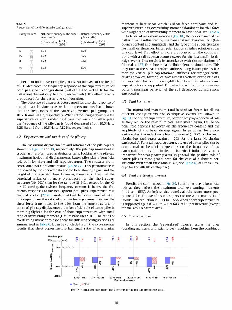
Table 5Frequencies of the different pile configurations.
Configurations Natural frequency of the super-structure (Hz)
Natural frequency of thepile cap (Hz)
(calculated byCHCH
1109
) (calculated byCHCH
1009
)
IS 1.94 6.28
VS 1.80 4.26
IT 1.70 7.12
VT 1.62 5.30
higher than for the vertical pile groups. An increase of the heightof C.G. decreases the frequency response of the superstructure forboth pile group configurations (�0.24 Hz and �0.18 Hz for thebatter and the vertical pile group, respectively). This effect is morepronounced for the batter pile configuration.
The presence of a superstructure modifies also the response ofthe pile cap. Previous tests without superstructures have shownthat the frequencies of the batter and vertical pile groups are10.6 Hz and 6.0 Hz, respectively. When introducing a short or a tallsuperstructure with similar rigid base frequency on batter piles,the frequency of the pile cap is found decreased (from 10.6 Hz to6.28 Hz and from 10.6 Hz to 7.12 Hz, respectively).
4.2. Displacements and rotations of the pile cap
The maximum displacements and rotations of the pile cap areshown in Figs. 17 and 18, respectively. The pile cap movement iscrucial as it is often used in design criteria. Looking at the pile capmaximum horizontal displacements, batter piles play a beneficialrole both for short and tall superstructures. These results are inaccordance with previous results [26,28,27]. This performance isinfluenced by the characteristics of the base shaking signal and theheight of the superstructure. However, these tests show that thebeneficial influence is more pronounced for the short super-structure (30–50%) than for the tall one (8–34%), except for the Kb�4 dB earthquake (whose frequency content is below the fre-quency responses of the total system (soil, piles, superstructure)).Giannakou et al. [27,28] pointed out that the performance of batterpile depends on the ratio of the overturning moment versus theshear force transmitted to the piles from the superstructure. Interms of pile cap displacement, the beneficial role of batter piles ismore highlighted for the case of short superstructure with smallratio of overturning moment (OM) to base shear (BS). The ratios ofoverturning moment to base shear for different configurations aresummarized in Table 6. It can be concluded from the experimentalresults that short superstructure has small ratio of overturning
Fig. 17. Normalized maximum displaceme
10
moment to base shear which is shear force dominant; and tallsuperstructure has overturning moment dominant inertial forcewith larger ratio of overturning moment to base shear, see Table 6.
In terms of maximum rotations (Fig. 18), the performance of thebatter piles is influenced by the base shaking characteristics (fre-quency content and amplitude) and the type of the superstructure.For small earthquakes, batter piles induce a higher rotation at thepile cap level. This effect is more pronounced for the configura-tions with a tall superstructure (except for the last small North-ridge event). This result is in accordance with the conclusions ofGiannakou [27] from linear elastic finite element simulations. Thismay due to the shear interface stiffness along batter piles is lessthan the vertical pile cap rotational stiffness. For stronger earth-quakes however, batter piles have almost no effect for the case of atall superstructure or only a slightly beneficial role when a shortsuperstructure is supported. This effect may due to the more im-portant nonlinear behavior of the soil developed during strongearthquakes.
4.3. Total base shear
The normalized maximum total base shear forces for all thedifferent configurations and earthquake events are shown inFig. 19. For a short superstructure, batter piles play a beneficial roleas they reduce the maximum total base shear. Again, this bene-ficial role depends however on the frequency content and theamplitude of the base shaking signal. In particular for strongearthquakes, the reduction is less pronounced (�35% for the smallNorthridge earthquake against �20% for the large Northridgeearthquake). For a tall superstructure, the use of batter piles can bedetrimental or beneficial depending on the frequency of theearthquake and its amplitude. Its beneficial influence is moreimportant for strong earthquakes. In general, the positive role ofbatter piles is more pronounced for the case of a short super-structure with small ratio (about 3–5, see Table 6) of OM/BS (ex-cept for the 4th Kb earthquake).
4.4. Total overturning moment
Results are summarized in Fig. 20. Batter piles play a beneficialrole as they reduce the maximum total overturning moments(�11 to �55%). As before, this beneficial role seems more pro-nounced for the case of a short superstructure with small ratio ofOM/BS. The reduction is �14 to �55% when short superstructureis supported against �11 to �25% for a tall superstructure (exceptfor the 4th Kb earthquake).
4.5. Stresses in piles
In this section, the “generalized” stresses along the piles(bending moments and axial forces) resulting from the combined
nts of the pile cap (prototype scale).

Fig. 18. Normalized maximum rotations of the pile cap.
Table 6Ratios of overturning moment to base shear for the different configurations.
Configurations 1. Mj�1 dB
2. Nr�20 dB
3. Nr�9 dB
4. Kb�4 dB
5. Mj�1 dB
6. Nr�20 dB
IS 4.13 3.70 4.67 4.22 4.04 3.64
VS 3.90 3.44 4.35 4.60 3.81 3.36
IT 7.06 6.46 6.57 6.86 5.89 6.21
VT 8.33 9.19 6.95 6.91 8.59 7.48
kinematic and inertial interactions are analyzed and discussed.The envelope curves of the maximum stresses and the normalizedpeak values are compared for the different pile groups and su-perstructure configurations.
4.5.1. Residual bending momentsFig. 21 shows the accumulated residual bending moment pro-
files along the piles for successive earthquake events. The presenceof batter piles influences the shape of the profiles inducing ingeneral a “C” and not the “S” shape profile obtained for vertical pilegroups. For both pile group configurations, the height of the su-perstructure affects the depth of the maximum residual bendingmoment. For a short superstructure, batter piles increase thisdepth from 4D to 6D during the first two small earthquakes. Thisdepth however remains unchanged during and after the strongearthquakes.
Concerning the maximum values of the residual bending mo-ment, as shown in Fig. 22, batter piles have a detrimental effectregardless the type of the supported superstructure. However, theheight of the superstructure, the base shaking characteristics andthe loading history influence the effect of the batter piles. Once theresidual bending moment was developed during the strong
Fig. 19. Normalized maximum total ba
11
earthquakes, the subsequent small earthquakes cannot induceadditional residual bending moments. This detrimental behavior ismore pronounced when a tall superstructure is supported , exceptfor the strong 3rd Northridge earthquake.
4.5.2. Maximum bending momentsFig. 23 shows the normalized maximum bending moment
profiles. Because of the presence of the residual bending moments,the curves for subsequent earthquakes are dragged and distortedin an asymmetric way. As a consequence, a “C” shape is still no-ticeable for the batter pile group. However, it is difficult to pre-cisely describe the shape of the bending moment envelope curvesfor the vertical pile group. In general, the maximum values of thetotal bending moments for the vertical pile group are equallyimportant below and above the soil surface. It is also observed thatbatter piles result in a reduction of the bending moment at the pilehead. This observation is not in accordance with the results ob-tained on micropiles by Juran et al. [26] where higher bendingmoments were found at the pile head connections. This differencemay due to the different superstructure configurations. In the testsperformed by Juran et al. [26], only a pile cap was considered as asuperstructure. However, in this paper, two more slender (shortand tall) superstructures are used. It may also due to a differentratio of pull out resistance over bending moment resistance of thepile (the micropiles used by Juran had lower bending momentresistance).
Fig. 24 presents the normalized maximum total bending mo-ments. In general, batter piles reduce the maximum total bendingmoment. This effect is more pronounced for the case of a shortsuperstructure with a small ratio of OM/BS. When a short super-structure is supported, the performance of batter piles seems to benot influenced by the frequency content of the base shaking sig-nals. For the case of a tall superstructure, the performance ofbatter piles is influenced by the base shaking characteristics.
se shear forces (prototype scale).
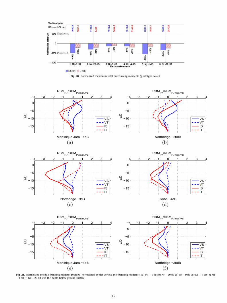
Fig. 20. Normalized maximum total overturning moments (prototype scale).
Fig. 21. Normalized residual bending moment profiles (normalized by the vertical pile bending moment): (a) Mj �1 dB (b) Nr �20 dB (c) Nr �9 dB (d) Kb �4 dB (e) Mj�1 dB (f) Nr �20 dB. z is the depth below ground surface.
12

Fig. 22. Normalized maximum residual bending moments (prototype scale).
Fig. 23. Normalized maximum bending moment profiles (normalized by the vertical pile bending moment): (a) Mj �1 dB (b) Nr �20 dB (c) Nr �9 dB (d) Kb �4 dB (e) Mj�1 dB (f) Nr �20 dB. z is the depth below ground surface.
4.5.3. Axial forcesSince only 3 strain gauges were used to measure the axial force,
it was not possible to identify the axial force profiles. The
13
maximum total axial force is discussed hereafter (no importantresidual effects were observed). The distance between the bottomof the pile cap and the soil surface remained almost the same

Fig. 24. Normalized maximum total bending moments (prototype scale).
before and after the test, no obvious relative displacement wasobserved in the axial direction. According to Nazir and Nasr [41], indense sand, within a small range of axial displacement, piles didnot exceed their axial capacities. Similar to the total bendingmoments, batter piles often reduce the maximum axial force(Fig. 25). This effect is however relatively small (most of the timeless than 30%) and is influenced by the frequency content and theamplitude of the base signal. For the case of a tall superstructure,the beneficial role of batter piles is less influenced. This reductioneffect of batter piles on the axial forces could due to the presenceof the superstructures, since it has been shown in Sections 4.3 and4.4 that, in general, the batter pile-superstructure systems attractless base shear forces and overturning moments.
5. Overall behavior
The overall experimental behavior of batter and vertical pilefoundations with short and tall superstructures under successiveearthquake excitations can be summarized as follows:
1. The presence of batter piles contributes to a higher horizontalstiffness (comparing to the vertical pile configuration) and thuscauses an increase of the corresponding frequencies.
2. An increase of the height of the center of gravity (C.G.) of thesuperstructure amplifies the influence of the Seismic Soil-Pile-Superstructure Interaction (SSPSI) on the frequency responsefor both pile group configurations. The influence of the C.G. ismore pronounced for batter piles.
3. Batter piles decrease the horizontal pile cap displacements. Thiseffect is influenced by the characteristics of the base shakingsignal and it is more pronounced for short superstructures.
4. Batter piles tend to induce higher pile cap rotations for smallearthquakes, especially for tall superstructures. This may due tothe shear interface stiffness along batter piles is less than the
Fig. 25. Normalized maximum a
14
vertical pile cap rotational stiffness. However for strong earth-quakes batter piles play a beneficial role in decreasing the pilecap rotations, especially for short superstructures. This effectmay due to the more important nonlinear behavior of the soildeveloped during strong earthquakes.
5. Batter piles tend to decrease the total overturning moment andthe total base shear, especially for short superstructures.
6. The use of batter piles induces higher residual bending mo-ments. This detrimental performance is more pronounced fortall superstructures. Batter piles also influence the shape of theresidual bending moment profiles.
7. Batter piles reduce the total bending moment. This beneficialperformance is not so much influenced by the characteristics ofthe base shaking signal for the case of short superstructures.
8. Batter piles reduce the axial forces. This effect is probably due tothe batter pile-superstructure systems that attract less baseshear forces and overturning moments. This beneficial effect isless influenced by the characteristics of base shaking signal forthe case of tall superstructures.
In general, batter piles supporting short superstructures i.e.where inertial shear forces dominate, seem to have a more sig-nificant beneficial effects.
6. Conclusions
In this paper, an experimental dynamic centrifuge modelingcampaign is presented to study the behavior of pile foundationsconsidering Seismic Soil-Pile-Superstructure Interaction (SSPSI).This study enriches the database of the effect of batter piles on theseismic response of pile group. The influence of the height ofgravity center on the performances of batter piles is highlighted.Cross comparisons are carried out to investigate the performanceof different pile foundations with vertical or batter piles, short or
xial forces (prototype scale).
tall superstructures and various earthquake loadings. Although theuse of batter piles seems to have in general a positive effect interms of displacements and total forces, it is found that the per-formance can vary depending on the characteristics of the baseshaking signal and of the height of the center of gravity of thesupported superstructures.
This paper extends the work of Li et al [42] to more general realearthquake loading and the results confirm the conclusions thatbatter piles are likely to have beneficial performance. In addition,these beneficial effects are more often observed for batter pileswith a short superstructure. In order to be able to predict thebeneficial or detrimental behavior of vertical and batter pilefoundations, simplified numerical models based on the macro-element approach [43,44] have been recently developed to simu-late the nonlinear behavior of pile foundations.
The initial stress state of the batter piles could also significantlyinfluence their performance, which should attract attentions infuture experimental and numerical campaigns.
Acknowledgments
The financial support of IFSTTAR (Institut français des scienceset technologies des transports, de l′aménagement et des réseaux)and of the Région Pays de la Loire is gratefully acknowledged. Theauthors would like also to thank the valuable support and helpfrom the technical staff of the IFSTTAR centrifuge team.
References
[1] AFPS. Recommandations AFPS 90. Presses des Ponts et Chaussées; 1990.[2] Eurocode8. Eurocode 8: design of structures for earthquake resistance-Part 5:
foundations, retaining structures and geotechnical aspects. Belgium: EuropeanCommittee for Standardization (CEN); 2004.
[3] Gerolymos N, Giannakou A, Anastasopoulos I, Gazetas G. Evidence of bene-ficial role of inclined piles: observations and summary of numerical analyses.Bull Earthq Eng 2008;6(4):705–22. http://dx.doi.org/10.1007/s10518-008-9085-2.
[4] Gazetas G, Mylonakis G. Seismic soil-structure interaction: new evidence andemerging issues. In: Proceedings of geotechnical earthquake engineering andsoil dynamics III; 1998. p. 1119–74.
[5] Pender MJ. Aseismic pile foundation design analysis. Bull N Z Soc Earthq Eng1993;26(1):49–160.
[6] Berrill JB, Christensen SA, Keenan RP, Okada W, Pettinga JR. Case study oflateral spreading forces on a piled foundation. Géotechnique 2001;51(6):501–17. http://dx.doi.org/10.1680/geot.2001.51.6.501.
[7] Harn R. Have batter piles gotten a bad rap in seismic zones (or everything youwanted to know about batter piles but were afraid to ask). In: Proceedings ofPorts 2004: port development in the changing world; 2004. p. 1–10. ⟨http://dx.doi.org/10.1061/40727(2004)13⟩.
[8] Meyerhof GG, Ranjan G. The bearing capacity of rigid piles under inclinedloads in sand. I: vertical piles. Can Geotech J 1972;9(4):430–46. http://dx.doi.org/10.1139/t72-043.
[9] Meyerhof GG, Ranjan G. The bearing capacity of rigid piles under inclinedloads in sand. II: batter piles. Can Geotech J 1973;10(1):71–85. http://dx.doi.org/10.1139/t73-006.
[10] Meyerhof GG, Ranjan G. The bearing capacity of rigid piles under inclinedloads in sand. III: pile groups. Can Geotech J 1973;10(3):428–38. http://dx.doi.org/10.1139/t73-036.
[11] Meyerhof GG, Yalcin AS, Mathur SK. Ultimate pile capacity for eccentric in-clined load. J Geotech Eng 1983;109(3):408–23. http://dx.doi.org/10.1061/(ASCE)0733-9410(1983)109:3(408).
[12] Meyerhof GG, Sastry VVRN. Bearing capacity of rigid piles under eccentric andinclined loads. Can Geotech J 1985;22(3):267–76. http://dx.doi.org/10.1139/t85-040.
[13] Meyerhof GG, Yalcin AS. Behaviour of flexible batter piles under inclined loadsin layered soil. Can Geotech J 1993;30(2):247–56. http://dx.doi.org/10.1139/t93-021.
[14] Meyerhof GG, Yalcin AS. Bearing capacity of flexible batter piles under ec-centric and inclined loads in layered soil. Can Geotech J 1994;31(4):583–90.http://dx.doi.org/10.1139/t94-068.
[15] Pinto P, McVay M, Hoit M, Lai P. Centrifuge testing of plumb and battered pilegroups in sand. Transp Res Rec: J Transp Res Board 1997;1569:8–16. http://dx.doi.org/10.3141/1569-02.
15
[16] McVay MC, Gardner R, Zhang L. Centrifuge modeling of laterally loaded bat-tered pile groups in sand. U. S. Department of Commerce National TechnicalInformation Service; 1997.
[17] Zhang L, McVay MC, Lai PW. Centrifuge modelling of laterally loaded singlebattered piles in sands. Can Geotech J 1999;36(6):1074–84. http://dx.doi.org/10.1139/t99-072.
[18] Zhang LM, McVay MC, Han SJ, Lai PW, Gardner R. Effects of dead loads on thelateral response of battered pile groups. Can Geotech J 2002;39(3):561–75.http://dx.doi.org/10.1139/t02-008.
[19] Escoffier S, Chazelas JL, Garnier J. Centrifuge modelling of raked piles. BullEarthq Eng 2008;6:689–704. http://dx.doi.org/10.1007/s10518-008-9094-1.
[20] Escoffier S. Experimental study of the effect of inclined pile on the seismicbehavior of pile group. Soil Dyn Earthq Eng 2012;42:275–91. http://dx.doi.org/10.1016/j.soildyn.2012.06.007.
[21] Chazelas JL, Escoffier S, Garnier J, Thorel L, Rault G. Original technologies forproven performances for the new LCPC earthquake simulator. Bull Earthq Eng2008;6(4):723–8. http://dx.doi.org/10.1007/s10518-008-9096-z.
[22] Okawa K, Kamei H, Kimura M, Zhang F. Dynamic behaviour of a group-pilefoundation with inclined piles in loose sand. In: Proceedings of Internationalconference on physical modelling in geotechnics: ICPMG'02; 2002. pp. 729–34.
[23] Boland JC, Schlechter SM, McCullough NJ, Dickenson SE, Kutter BL, Wilson DW.Pile-supported Wharf centrifuge model (JCB01). Tech. Rep. October. Davis:Center for Geotechnical Modeling University of California; 2001.
[24] Boland JC, Schlechter SM, McCullough NJ, Dickenson SE, Kutter BL, Wilson DW.Pile-supported Wharf centrifuge model (SMS02). Tech. Rep. October. Davis:Center for Geotechnical Modeling University of California; 2001.
[25] Schlechter S, Dickenson S, McCullough N, Boland J. Influence of batter piles onthe dynamic behavior of pile-supported Wharf structures. In: Proceedings ofPorts 2004: port development in the changing world. Houston, Texas, UnitedStates: American Society of Civil Engineers; 2004. pp. 1–10. ⟨http://dx.doi.org/10.1061/40727(2004)12⟩.
[26] Juran I, Benslimane A, Hanna S. Engineering analysis of dynamic behavior ofmicropile system. Transp Res Rec: J Transp Res Board 2001;1772:91–106. http://dx.doi.org/10.3141/1772-11.
[27] Giannakou AK. Seismic behavior of inclined piles [Ph.D. dissertation]. NationalTechnical University of Athens; 2007.
[28] Giannakou A, Gerolymos N, Gazetas G, Tazoh T, Anastasopoulos I. Seismicbehavior of batter piles: elastic response. J Geotech Geoenviron Eng 2010;136(9):1187–99. http://dx.doi.org/10.1061/(ASCE)GT.1943-5606.0000337.
[29] Shahrour I, Juran I. Seismic behaviour of micropile systems. Proceedings of theInstitution of Civil Engineers-Ground Improvement 2004;8(3):109–20. http://dx.doi.org/10.1680/grim.2004.8.3.109.
[30] Mokwa RL, Duncan JM. Rotational restraint of pile caps during lateral loading. JGeotech Geoenviron Eng 2003;129(9):829–37. http://dx.doi.org/10.1061/(ASCE)1090-0241(2003)129:9(829).
[31] Beatty CI. Lateral test on pile groups. Found Facts 1970;6(1):18–21.[32] Kim JB, Brungraber RJ, Singh LP. Pile cap soil interaction from full-scale lateral
load tests. J Geotech Eng Div 1979;105(5):643–53.[33] Liu JL, Yuan ZL, Zhang KP. Cap-pile-soil interaction of bored pile groups. In:
Proceedings of the eleventh international conference on soil mechanics andfoundation engineering. San Francisco; 1985, p. 1433–36.
[34] Zafir Z, Vanderpool WE. Lateral response of large diameter drilled shafts: I-15/US 95 load test program. In: Proceedings of the 33rd engineering geology andgeotechnical engineering symposium. Reno: University of Nevada; 1998. p.161–76.
[35] Harris CM, Piersol AG. Harris' shock and vibration handbook.New York:McGraw-Hill; 2002.
[36] Zeng X, Schofield AN. Design and performance of an equivalent-shear-beamcontainer for earthquake centrifuge modelling. Géotechnique 1996;46(1):83–102. http://dx.doi.org/10.1680/geot.1996.46.1.83.
[37] Teymur B, Madabhushi SPG. Experimental study of boundary effects in dy-namic centrifuge modelling. Géotechnique 2003;53(7):655–63. http://dx.doi.org/10.1680/geot.2003.53.7.655.
[38] Arias A. A measure of earthquake intensity. In: Hansen R, editor. Seismic de-sign for nuclear power plants. MIT Press; 1970. p. 438–83.
[39] Escoffier S. Seismic and sinusoidal tests on pile group (Tech. rep.). IFSTTAR;2011.
[40] Li Z, Escoffier S, Kotronis P. Using centrifuge tests data to identify the dynamicsoil properties: application to Fontainebleau sand. Soil Dyn Earthq Eng2013;52:77–87. http://dx.doi.org/10.1016/j.soildyn.2013.05.004.
[41] Nazir A, Nasr A. Pullout capacity of batter pile in sand. J Adv Res 2013;4(2):147–54. http://dx.doi.org/10.1016/j.jare.2012.04.001.
[42] Li Z, Escoffier S, Kotronis P. Centrifuge modeling of batter pile foundationsunder sinusoidal dynamic excitation. Bull Earthq Eng 2016;14(3):673–97.http://dx.doi.org/10.1007/s10518-015-9859-2.
[43] Li Z, Kotronis P, Escoffier S. Numerical study of the 3D failure envelope of asingle pile in sand. Comput Geotech 2014;62:11–26. http://dx.doi.org/10.1016/j.compgeo.2014.06.004.
[44] Li Z, Kotronis P, Escoffier S, Tamagnini C. A hypoplastic macroelement forsingle vertical piles in sand subject to three-dimensional loading conditions.Acta Geotech 2016;11(2):373–90. http://dx.doi.org/10.1007/s11440-015-0415-7.