centro nacional de metrología - bipm - bipm · ilieff s. inti, instituto nacional de tecnología...
TRANSCRIPT

SIM.L-K1:2007 Calibration of Gauge Blocks by Optical Interferometry 1 / 43
2012-07-15
Centro Nacional de Metrología
SIM Regional Key Comparison SIM.L-K1.2007
Calibration of Gauge Blocks by Optical Interferometry
FINAL REPORT
JULY 2012
Colín C. CENAM, Centro Nacional de Metrología
Viliesid M. CENAM, Centro Nacional de Metrología
Chaudhary K. P. NPLI, National Physical Laboratory INDIA
Decker J. NRC-CNRC, National Research Council Canada
Dvořáček F. CMI, Czech Metrology Institute
Franca R. INMETRO, Instituto Nacional de Metrología
Ilieff S. INTI, Instituto Nacional de Tecnología Industrial
Rodríguez J. CEM, Centro Español de Metrología
Stoup J. NIST, National Institute of Standards and Technology
Centro Nacional de Metrología (CENAM) km 4.5 Carretera a Los Cués,
El Marqués, Querétaro 76246, MEXICO

SIM.L-K1:2007 Calibration of Gauge Blocks by Optical Interferometry 2 / 43
2012-07-15
Contents
SIM Regional Key Comparison SIM.L-K1.2007..................................................................1
Calibration of Gauge Blocks by Optical Interferometry.......................................................1
1. Introduction..................................................................................................................3
2. Participants..................................................................................................................4
3. Circulation Schedule....................................................................................................5
4. Comparison Artifacts ...................................................................................................5
5. Measurement Protocol ................................................................................................6
6. Measuring Instruments ................................................................................................6
7. State and Behavior of Artifacts ....................................................................................6
7. 1 State of the Artifacts upon Reception...................................................................6
7. 2 Stability of the Standards .....................................................................................8
8. Measurement Results of Participants........................................................................11
8.1 Measurement of the Central Length...................................................................11
8.2 Measurement Difference of Length between the Two Measuring Faces ...........15
8.3 Phase-change Correction...................................................................................16
9. Analysis Method ........................................................................................................16
9.1 Key Comparison Reference Value (KCRV) Determination ................................16
9.2 Criteria to Determine the Largest Sub-set of “Consistent” Results to Compute the KCRV ......................................................................................................................16
9.3 KCRV Uncertainty ..............................................................................................17
10. Results of the Comparison.....................................................................................19
10.1 KCRV Determination ..........................................................................................19
10.2 Participants Results............................................................................................20
11. Discussion and Conclusions ..................................................................................22
11.1 Discussion ..........................................................................................................22
11.2 Conclusions........................................................................................................22
12. Acknowledgements................................................................................................23
13. References.............................................................................................................31
Annex A Elimination of Inconsistent Results .............................................................32
Annex B Calculation of Alternate Statistical Parameters. ..........................................38
Annex C Correspondence with Participants. .............................................................40
C.1 Correspondence with NMISA. ............................................................................40
C.2 Correspondence with CMI..................................................................................40
Annex D Analysis of Results considering CMI correction. .........................................41
Annex E Phase Change Correction Determination by the Stack Method..................43

SIM.L-K1:2007 Calibration of Gauge Blocks by Optical Interferometry 3 / 43
2012-07-15
1. Introduction
The Mutual Recognition Arrangement (MRA) of the Conférence Internationale des Poids et Mesures (CIPM) signed by the National Metrology Institutes (NMI) of different nations provides mutual recognition among the NMI of their national standards and their calibration services. A database has been set up by the Bureau Interantional des Poids et Mesures (BIPM) at its website where the Calibration and Measurement Capabilities (CMC) of each NMI are posted. To support the CMC claims of the NMI, the MRA requires, among other things, that they participate, on a regular basis, in Key Comparisons (KC) that test key measuring techniques. This would prove their technical competence, that they can provide this calibration service with the claimed uncertainty of the corresponding CMC and that they have metrological equivalence with the other signatory NMI that provide the same calibration service.
KC should take place at the highest level amongst the members of the corresponding Consultative Committee (CC), in this case the Consultative Committee for Length (CCL). Similar regional KC should also be organized in every region with at least a few NMI from the region participating in the regional comparison as well as in the CCL KC.
The CIPM has also instructed the different CC to identify key techniques in order to define KC. The calibration of Gauge Blocks (GB) by optical inteferometry has been identified as a key measuring technique by the Consultative Committee for Length (CCL). In one hand it requires good technical expertise and skills, the use of sophisticated equipment and stringent laboratory conditions; but in the other hand it is an unavoidable step in the dissemination of the length unit and therefore it is of paramount importance. These KC have been designated as K1 comparisons.
Both levels of comparisons should be organized regularly in time at a frequency established by each CC. The present comparison, SIM.L-K1.2007, is the second K1 comparison organized by SIM region since the signature of the MRA. It is intended to support and maintain the posted CMC of the NMI of the Americas that offer GB calibration by optical interferometry on the database, and, eventually, any other calibration services that stems out of this key technique.
The mesurand is the central length of the GB as defined in [1]. Additionally, for those laboratories willing to participate, a Pilot Study on the Optical Phase Change Correction on the Reflection of Light has been organized along with SIM.L-K1.2007 using the same GB and a set of platens that were circulated along with the GB. The results will be part of a separate Pilot Study report and are not part of this comparison.
The optical interferometry measurement of the GB is a first stage of the circulation of these GB. A second stage has been organized to measure them by mechanical comparison. The circulation of this second stage has just ended and, therefore, we can now disclose the results contained in this report.
The comparison had nine participants, five from the Americas, and four invited ones from other regions. The circulation took more than two years, from November 2007 until March 2010. The exercise was quite delayed as the allocated time periods could not be respected at several points.

SIM.L-K1:2007 Calibration of Gauge Blocks by Optical Interferometry 4 / 43
2012-07-15
2. Participants
A total of nine NMI participated in this comparison that circulated 14 GB of different lengths and materials. The following table lists the information on the participating NMI.
Contact NMI Information Joaquín Rodríguez González, Emilio Prieto Esteban
CEM, Centro Español de Metrología Alfar, 2. Tres Cantos 28760 Madrid, España
Tel. +34 91 8074 796 / 801 Fax +34 91 8074 807 e-mail: [email protected] ; [email protected]
Carlos Colín Castellanos, Miguel Viliesid Alonso
CENAM, Centro Nacional de Metrología km 4.5 Carretera a los Cués, El Marqués CP 76241, Querétaro, MEXICO
Tel. +52 442 211 0500 Fax +52 442 211 0577 e-mail: [email protected] ; [email protected].
Ing. Vladimir Stezka Ing. František Dvořáček
CMI, Czech Metrology Institute Slunecna 23 460 01 Liberec Czech Republic
Tel. +42 485 107 532 Fax +42 485 104 466 e-mail: [email protected] [email protected]
Hakima Belaïdi Ricardo dos Santos França
INMETRO, Instituto Nacional de Metrologia, Normalização e Qualidade Industrial. Av. N.Sra. das Graças, 50 – Villa Operária – Xerém – Duque de Caixas – RJ. CEP 25250-020 Brasil
Tel. +55 21 2679-9271 Fax +55 21 2679-9207 e-mail: [email protected] [email protected]
Sergio Nicolás Ilieff, Carina Bastida
INTI, Instituto Nacional de Tecnología Industrial FISICA Y METROLOGÍA; Laboratorio de Óptica y Dimensional. Av. Gral. Paz 5445 – CC 157 – B1650WAB – San Martín, Bs.As.; Argentina.
Tel. +54 11 47246200 Fax +54 11 47134140 e-mail: [email protected] ; [email protected]
John Stoup NIST, National Institute of Standards and Technology Room B113, Metrology Building Gaithersburg, MD 20899-0001 USA
Tel. +1 301 975 3476 Fax + 1 301 869 0822 e-mail: [email protected]
Sam Thema NMISA, National Metrology Institute of South Africa Private Bag X34 Lynnwood Ridge 0040 South Africa
Tel. +27 12 841 4798 Fax +27 12 841 2131 e-mail: [email protected]
K. P. Chaudhary NPLI, National Physical Laboratory INDIA Dr. K,S. Krishnan Road, New Delhi 110012, India
Tel. +91 11 25732865 Fax +91 11 25726938 e-mail: [email protected]
Jennifer Decker1, Pierre Dubé
National Research Council Canada Measurement Science and Standards Portfolio 1200 Montreal Road Campus Bldg M-36 Ottawa, Ontario, CANADA K1A 0R6
Tel. +1.613.991.1633 Fax +1.613.952.1394 e-mail: [email protected] ; pierre.dubé@nrc-cnrc.gc.ca.
Table 1. List of participants in comparison SIM.L-K1.2007.
1 Formerly: Institute for National Measurement Standards (INMS); update contact: Pierre Dube [email protected]

SIM.L-K1:2007 Calibration of Gauge Blocks by Optical Interferometry 5 / 43
2012-07-15
3. Circulation Schedule
The circulation of the artifacts was very delayed mainly due to customs clearance delays in several countries. A circulation time of 14 months was initially scheduled and it took 30 months, more than the double of the initial scheduled time. Table 2 shows the actual dates of reception and shipment of the artifacts by the participants as well as the date of reception of the participant’s results by the pilot laboratory.
Dates NMI
Reception Shipment Reception of Results
CENAM (Pilot) 2007-11-01 2007-11-10 CEM 2007-11-23 2008-01-14 2008-09-01 NPLI 2008-03-02 2008-06-09 2009-08-07 CMI 2008-06-16 2008-08-05 2008-10-17
NMISA 2008-09-10 2008-11-27 Did not send-in results NRC-INMS 2008-12-04 2009-04-17 2009-08-25
NIST 2009-04-20 2009-07-15 2010-03-02 INMETRO 2009-08-11 2009-09-08 2009-09-21
INTI 2009-11-13 2010-01-11 2010-01-11 CENAM (Pilot) 2010-03-02 2010-04-25
Table 2. SIM.L-K1.2007 dates of reception and shipment of artifacts and reception of results by the pilot lab.
4. Comparison Artifacts
A total of 14 grade K (according to [1]) rectangular GB were selected for the exercise. Seven steel GB and seven ceramics GB covering the range of short GB (from 0.5 mm to 100 mm). The specifications on the GB are shown in tables 3 and 4. The associated Coefficients of Thermal Expansion (CET) shown in the tables are those quoted by the manufacturers.
Nominal Length (mm)
Serial Number Coefficient of Thermal Expansion ( 10-6 K-1 )
Manufacturer
1.000 5 010223 10.9 1 Mitutoyo 5 000482 10.9 ± 1 Mitutoyo 7 010764 10.9 1 Mitutoyo
10 001329 10.9 ± 1 Mitutoyo 50 012254 10.9 1 Mitutoyo 75 010630 10.9 1 Mitutoyo 100 010850 10.9 1 Mitutoyo
Table 3. Steel Gauge Blocks.

SIM.L-K1:2007 Calibration of Gauge Blocks by Optical Interferometry 6 / 43
2012-07-15
Nominal Length (mm)
Serial Number Coefficient of Thermal Expansion ( 10-6 K-1 )
Manufacturer
1.000 5 000288 9.3 1 Mitutoyo 5 051836 9.3 1 Mitutoyo 7 010323 9.3 1 Mitutoyo
10 052351 9.3 1 Mitutoyo 50 011002 9.3 1 Mitutoyo 75 010370 9.3 1 Mitutoyo 100 010773 9.3 1 Mitutoyo
Table 4. Ceramics Gauge Blocks.
5. Measurement Protocol
Detailed Measurement Instructions were included in the Comparison Protocol. The GB were supposed to be measured wrung to the platens or optical flats that the participant laboratories currently use to offer their gauge block calibration service.
Gauge block calibration by optical interferometry should be performed with the GB in vertical position wrung to a platen as indicated in [1]. The gauge block central length, lc, is the perpendicular distance between the central point of the free measurement surface of the gauge block and the surface where it is wrung.
The values asked to be reported in the protocol were the deviations from nominal length (ln) determined at the center for each measuring face “A” and “B”, ecX = lc – ln, (where X = “A” or “B”); the average of both values, eavg; the so called phase change correction, l; and the corrected average deviation after applying the phase change correction, ec.
The method most commonly used to determine the phase change correction, l is the stack method and it is described in Annex E.
6. Measuring Instruments
All participant laboratories measured the GB by optical absolute interferometry applying the method of exact fractions. The systems used, traceability, light sources and laboratory temperature variations of the participants are listed in table 5.
7. State and Behavior of Artifacts
7. 1 State of the Artifacts upon Reception
The participants were to inspect the state of the artifacts upon reception and inform the pilot according to the protocol. Although the selected GB were not new, they were in good conditions for measurement. A few of the steel GB suffered some damage after the circulation, but the results obtained in the comparison prove that the damages did not hamper or alter the measurements; and the pilot laboratory was able to wring them all to a platen at the end of the circulation. Figures 1 through 4 show the physical conditions of

SIM.L-K1:2007 Calibration of Gauge Blocks by Optical Interferometry 7 / 43
2012-07-15
some of the damaged GB upon reception by the pilot laboratory at the end of the circulation.
NMI Manufacturer and Type of
Interferometer
Light sources and
wavelengths used
Traceability
Temperature variation range
during measurements
(°C)
CEM NPL-TESA, Twyman-Green
He-Ne 633 nm TESA laser, He-Ne 543 nm TESA laser,
To the Spanish realization of the metre: A 633 nm Iodine-stabilized laser; and to a UK 543 nm Iodine-stabilized laser.
19.891 – 20.156
CENAM NPL-TESA, Twyman-Green
He-Ne 633 nm TESA laser, He-Ne 543 nm TESA laser,
To the Mexican realization of the metre: A 633 nm Iodine-stabilized laser (CNM-PNM-2)
19.95 – 20.15
CMI NPL-TESA, Twyman-Green
He-Ne 633 nm TESA laser, He-Ne 543 nm TESA laser,
To the Czech National Standard of Length (He-Ne/I2 633nm, He-Ne/I2 543.5nm, fs comb)
19.640 – 20.198
INMETRO Jena Zeiss Michelson/Twyman-Green
Double cathode 114Cd spectral lamp
To SI standards of INMETRO
19.92 – 20.36
INTI NPL-TESA, Twyman-Green
He-Ne 633 nm TESA laser, He-Ne 543 nm TESA laser,
To SI standards of INTI Not specified
NIST Hilger He-NE 633 nm Spectra Physics laser,
NIST maintained Iodine- Stabilized Laser
20.028 – 20.035
NMISA
----- ------ ------- -----
NPLI NPL-TESA, Twyman-Green
He-Ne 633 nm TESA laser, He-Ne 543 nm TESA laser,
Not specified 19.6 – 20.3
NRC-INMS
NRC-INMS own design, Twyman-Green
He-Ne 633 nm COHERENT laser, He-Ne 612 nm TESA laser, He-Ne 543 nm TESA laser, He –Ne 1 152 nm laser,
The 633 nm is traceable to an Iodine-Stabilized laser. The other wavelengths are traceable to the primary time and frequency standard of Canada.
19.986 – 20.019 for steel 19.971 – 20.020 for ceramics
Table 5. GB interferometers, laser sources, traceability and temperature variation of the participant laboratories.

SIM.L-K1:2007 Calibration of Gauge Blocks by Optical Interferometry 8 / 43
2012-07-15
Problems on some GB were reported by two participant NMI:
CEM from Spain. o The Ceramics 100 mm GB (serial no. 010773) presented wringing
problems, but they were able to submit measurement results. o The case where the GB were packed was received with damages that
were apparently suffered during transportation between Mexico and Spain.
INMETRO from Brazil. o Reports having had difficulties in wringing some GB due to damage on the
measuring faces, but they were also able to provide measurement results.
Figures 1 and 2. Physical condition of the 1.000 5 mm GB and the 10 mm GB after circulation. Notice the scratches and spots on the measuring faces.
Figures 3 and 4. Physical condition of the 5 mm GB and the 100 mm GB after circulation. Notice the scratches and spots on the measuring face of the first one; and
indentations and scratches in second one.
7. 2 Stability of the Standards
The GB were measured several times by the pilot laboratory to verify their stability: when they were purchased (2002), two years before starting the comparison (Nov. 2005),

SIM.L-K1:2007 Calibration of Gauge Blocks by Optical Interferometry 9 / 43
2012-07-15
before circulating them (Nov. 2007) and at the end of the circulation (April 2010). Table 6 shows the deviations from nominal length determined at these different occasions for the steel GB, including the stated values on the certificates of the manufacturer. Graphs 1 through 7 show these values for each GB along with the corresponding standard uncertainty bars.
Deviation from nominal value (nm) Serial
Number
Nominal Length (mm)
Manufacturer certificate
2001 2002 2005 2007 2010
010223 1.000 5 0 5 3 -4 -9 000482 5 40 14 11 35 20 010764 7 30 19 13 -5 1 001329 10 50 31 22 37 21 012254 50 60 46 3 7 -3 010630 75 -50 -54 -104 -100 -107 010850 100 20 18 -50 -51 -64
Table 6. Pilot Laboratory measured values of the steel GB at different occasions.

SIM.L-K1:2007 Calibration of Gauge Blocks by Optical Interferometry 10 / 43
2012-07-15
Table 7 shows the deviations from nominal length determined at these different occasions for the ceramics GB, including the stated values on the certificates of the manufacturer. Graphs 8 through 14 show these values for each GB with its standard uncertainty bars.
Deviation from nominal value (nm) Serial
Number
Nominal Length (mm)
Manufacturer certificate
2001 2002
Manufacturer certificate
2005 2007 2010
000288 1.000 5 0 -6 ---- -14 7 051836 5 ---- ---- 13 12 8 010323 7 50 46 ---- 57 48 052351 10 ---- ---- 3 -13 -19 011002 50 90 95 ---- 139 117 010370 75 100 110 ---- 118 124 010773 100 -60 -42 ---- -34 -36
Table 7. Pilot Laboratory measured values of the ceramics GB in different occasions.

SIM.L-K1:2007 Calibration of Gauge Blocks by Optical Interferometry 11 / 43
2012-07-15
8. Measurement Results of Participants
All laboratories sent their results by e-mail. NRC-INMS sent them by parcel service as well. All information was received on the specified formats from appendices A, B, C, D and E of the Technical Protocol.
8.1 Measurement of the Central Length
Tables 8 and 9 and graphs 16 through 22, show the deviations of the central length with respect to nominal values and the claimed standard measurement uncertainties of each participant for the seven steel GB; and graph 15 show the claimed standard uncertainties of the participants.
Deviation from nominal length for Steel GB nm
Nominal Value mm CEM NPLI CMI NRC NIST INMETRO INTI CENAM
1.000 5 -10.5 -15 20.5 -18 -1 14 -13 -4 5 16.5 18 60 25 41 48 13 35 7 -1.5 -12 37.5 -3 4 24 -14 -5
10 28 56 62.5 26 44 37 23 37 50 -29.5 22 29.5 11 13 -10 -14 7 75 -156 25 -39 -95 -100 -114 -119 -100 100 -103 -28 -8 -35 -41 -58 -49 -51
Table 8. Measurement results of the participants for the Steel GB.

SIM.L-K1:2007 Calibration of Gauge Blocks by Optical Interferometry 12 / 43
2012-07-15
Claimed standard uncertainties for Steel GB nm
Nominal Value mm CEM NPLI CMI NRC NIST INMETRO INTI CENAM
1.000 5 9.4 11 9.4 15 9 8 11 9.6 5 9.5 12 9.4 15 9.4 9 11 9.6 7 9.5 12 9.4 15 9.5 9 11 9.7
10 9.6 13 9.5 15 9.8 9 11 9.8 50 11.9 16 10.9 25 13.5 16 16 14.8 75 14.4 23 12.5 16 15.7 22 21 19.4 100 17.3 26 14.5 16 18 28 27 24.5
Table 9. Claimed standard uncertainties of the participants for Steel GB.

SIM.L-K1:2007 Calibration of Gauge Blocks by Optical Interferometry 13 / 43
2012-07-15
Tables 10 and 11 and graphs 24 through 30, show the deviations of the central length with respect to nominal values and their claimed standard measurement uncertainties of each participant for the seven ceramics GB; and graph 23 show the claimed standard uncertainties of the participants.
Deviation from nominal length for Ceramics GB nm
Nominal Value mm CEM NPLI CMI NRC NIST INMETRO INTI CENAM
1.000 5 2 4 -1 11 -5 -6 -22 -14 5 16 11 9 16 14 6 1 12 7 44 60 53.5 66 54 43 36 57
10 -19 -14 -18.5 -1 -11 -19 -19 -13 50 94 147 114.5 130 109 92 96 139 75 98.5 156 140.5 151 138 124 126 118 100 -50 28 2 2 -16 -45 -21 -34
Table 10. Measurement results of the participants for Ceramics GB.
Claimed standard uncertainties for Ceramics GB nm
Nominal Value mm CEM NPLI CMI NRC NIST INMETRO INTI CENAM
1.000 5 9.4 11 9.4 15 9 11 11 11.1 5 9.5 12 9.4 15 9.4 11 11 11.1 7 9.5 12 9.4 15 9.5 11 11 11.1
10 9.5 13 9.5 15 9.8 12 11 11.2 50 11.6 16 10.9 15 13.5 16 15 15.3 75 13.8 23 12.5 16 15.7 21 19 19.3 100 16.5 26 14.5 16 18 26 26 23.8
Table 11. Claimed standard uncertainties of the participants for Ceramics GB.

SIM.L-K1:2007 Calibration of Gauge Blocks by Optical Interferometry 14 / 43
2012-07-15
SIM.L-K1:2007 Calibration of Gauge Blocks by Optical Interferometry 15 / 43
2012-07-15
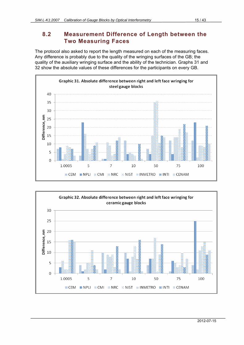
8.2 Measurement Difference of Length between the Two Measuring Faces
The protocol also asked to report the length measured on each of the measuring faces. Any difference is probably due to the quality of the wringing surfaces of the GB; the quality of the auxiliary wringing surface and the ability of the technician. Graphs 31 and 32 show the absolute values of these differences for the participants on every GB.

SIM.L-K1:2007 Calibration of Gauge Blocks by Optical Interferometry 16 / 43
2012-07-15
8.3 Phase-change Correction.
All participating laboratories applied the stack method to determine the phase-change correction for both materials except NIST. The latter laboratory assigns a value to each material and manufacturer of the GB according to a study they conducted in the 1990’s using their reference platens [3]. Table 12 summarizes the kind of platens the participants used and the phase-change correction values they submitted.
Steel Gauge Blocks Ceramics Gauge Blocks Participant
Platen material Phase-change correction (nm) Platen material Phase-change
correction (nm) CEM Steel B6(08/05A) -38.1 Ceramics (TESA-111) -4.9 NPLI Steel (Id. 2) -29 Steel (Id. 2) -19 CMI2 Steel (Id. 4) +12 (-12) Steel (Id. 4) -10 NRC Fused Silica Id. Zygo +50 Fused Silica Id. Zygo +53 NIST See [3] +28.9 See [3] +16.5
INMETRO Quartz
(17/19/18/14/15/18/11) +51 Quartz (15/16/11/12/18) +12
INTI Steel (TESA-83) -24 Steel (TESA-82) -21 CENAM Steel (TESA-86) -19 Steel (TESA-86) -16
Table 12. Phase-change correction of participants.
9. Analysis Method
9.1 Key Comparison Reference Value (KCRV) Determination
All usual parameters of the central tendency were calculated: the median, the simple mean and the inverse-variance weighted mean. All of these values appear on Annex B. However, the simple mean seemed the appropriate parameter to define the KCRV as all participants use the same calibration technique and state uncertainties that do not vary over a wide range.
9.2 Criteria to Determine the Largest Sub-set of “Consistent” Results to Compute the KCRV
The KCRV is determined, for each GB j, as the simple mean of the largest subset of mj participants which had “consistent” results3:
(1)
2 CMI informed that they made a mistake on the phase change correction after they received DRAFT A. Their corrected value is indicated in parenthesis. 3 Consistency is quoted because it is not checked in a rigorous statistical way but rather by the parameters that are described herein.

SIM.L-K1:2007 Calibration of Gauge Blocks by Optical Interferometry 17 / 43
2012-07-15
Where: eij is the deviation from nominal value of participant i, i= 1,2,…,m on GB j
mj is the number of consistent results of the participants, mj n, where n is the total number of participants that measured GB j
The number of participants in this comparison is n = 84.
Two parameters are considered in the elimination process of inconsistent results on GB j:
dij The absolute deviation from the mean of participant i on GB j; and ENij The Normalized error of participant i on GB j defined as
(2)
Where is the Expanded Uncertainty of deviation dij, computed as:
(3)
If laboratory i is taken in account in the calculation of the reference value; or
(4)
If laboratory i has been eliminated from the calculation of the reference value.
If ENij > 1 it is considered that the result is not consistent.
To establish the largest subset of laboratories that had consistent results, an iterative elimination process of outliers was applied for each GB j. To start, all participants are considered into the calculation of the simple mean and the corresponding Normalized Errors are computed. Then the data are ordered according to their deviations dij from largest to smallest along with their corresponding ENij values. If the first participant on the list, with the largest deviation also has an EN > 1, it is eliminated, m = n – 1 and the process is reiterated. The mean is recalculated and the remaining results are ordered according to their dij and along with their respective ENij. The process is repeated until no EN values greater than 1 are found. It is important to note that the largest values of dij do not necessarily correspond to the largest values of EN because the latter also depend on the declared uncertainty of the participant; although in most of cases they do. Figure 5 shows the block diagram of the elimination process applied on each GB j.
9.3 KCRV Uncertainty
4 CENAM, the pilot laboratory, contributes to the computation of the reference value only once with its first measurement.

SIM.L-K1:2007 Calibration of Gauge Blocks by Optical Interferometry 18 / 43
2012-07-15
The standard uncertainty corresponding to the reference value of GB j is given by the combined standard uncertainty of the simple mean, or internal uncertainty, of the mj consistent results:
where mj n (5)
Figure 5. Flow chart showing the elimination process of inconsistent results for each GB j.
This value is used to calculate in equation (4) in the previous section:
.
1.1 Consistency of the Results taken into the KCRV Calculation
The standard deviation of the simple mean, , or external uncertainty, of GB j is given by:

SIM.L-K1:2007 Calibration of Gauge Blocks by Optical Interferometry 19 / 43
2012-07-15
where mj n (6)
If the measurement results and their uncertainties are consistent, the external uncertainty should be smaller or equal to the internal uncertainty. This is tested by means of the Birge Ratio defined as:
where RB 1 for consistent results. (7)
10. Results of the Comparison
10.1 KCRV Determination
The Reference Values, , their Expanded Uncertainties, , as well as the number of
participants that contributed to the calculation, , for the different GB j of both materials are shown in Table 13.
Reference Values
Nominal Steel Ceramics
Length Ref.
Value,
Ref. Value,
1.005 -10.3 9.0 6 -3.9 7.8 8
5 24.8 9.2 6 10.6 7.9 8
7 -5.3 9.2 6 51.7 7.9 8
10 35.9 8.5 7 -14.3 8.1 8
50 4.8 14.1 6 105.9 11.3 6
75 -105.6 17.0 5 136.2 13.9 7
100 -43.7 19.3 6 -23.1 15.6 7
Table 13. Reference values (simple mean of largest sub-set of “consistent” results) deviations from Nominal Value with Expanded Uncertainty and number of values contributing to the
calculation of the Reference Value Computation (mj) for both steel and ceramics GB.
The elimination process of outliers is shown for each GB j in Annex A.

SIM.L-K1:2007 Calibration of Gauge Blocks by Optical Interferometry 20 / 43
2012-07-15
10.2 Participants Results.
Tables 14 and 15 show the differences of the results of the participants with respect to the Reference Values of each GB j, dij ; along with the Expanded Uncertainty of these differences, U(dij); and the corresponding Normalized Error, ENij.
Table 14 A. Deviation from reference value for each GB, dij; claimed expanded uncertainty (k=2), Uij; and Normalized Error ENij of the Steel GB for the first four participants.
NMI (i→) CEM CENAM CMI INMETRO
Nom L (j↓) dij U(dij) ENij dij U(dij) ENij dij U(dij) ENij dij U(dij) ENij
1.000 5 -0.3 18.8 0.0 6.3 19.2 0.3 30.8 18.8 1.5 24.3 16.0 1.3
5 -8.3 19.0 0.5 10.3 19.2 0.6 35.3 18.8 1.7 23.3 18.0 1.2
7 3.8 19.0 0.2 0.3 19.4 0.0 42.8 18.8 2.0 29.3 18.0 1.4
10 -7.9 19.2 0.4 1.1 19.6 0.1 26.6 19.0 1.3 1.1 18.0 0.1
50 -34.3 23.8 1.2 2.2 29.6 0.1 24.7 21.8 0.9 -14.8 32.0 0.5
75 -50.4 28.8 1.6 5.6 38.8 0.2 66.6 25.0 2.3 -8.4 44.0 0.2
100 -59.3 34.6 1.5 -7.3 49.0 0.2 35.7 29.0 1.0 -14.3 56.0 0.3

SIM.L-K1:2007 Calibration of Gauge Blocks by Optical Interferometry 21 / 43
2012-07-15
Table 14 B. Deviation from reference value for each GB, dij; claimed standard uncertainty, Uij; and Normalized Error ENij of the Steel GB for the last four participants.
Table 15 A. Deviation from reference value for each GB, dij; claimed standard uncertainty, Uij; and Normalized Error ENij of the Ceramics GB for the first four participants
Table 15 B. Deviation from reference value for each GB, dij; claimed standard uncertainty, Uij; and Normalized Error ENij of the Ceramics GB for the last four participants.
NMI (i→) INTI NIST NPLI NRC
Nom L (j↓) dij U(dij) ENij dij U(dij) ENij dij U(dij) ENij dij U(dij) ENij
1.000 5 -2.8 22.0 0.1 9.3 18.0 0.5 -4.8 22.0 0.2 -7.8 30.0 0.3
5 -11.8 22.0 0.6 16.3 18.8 0.9 -6.8 24.0 0.3 0.3 30.0 0.0
7 -8.8 22.0 0.4 9.3 19.0 0.5 -6.8 24.0 0.3 2.3 30.0 0.1
10 -12.9 22.0 0.6 8.1 19.6 0.4 20.1 26.0 0.9 -9.9 30.0 0.4
50 -18.8 32.0 0.6 8.2 27.0 0.3 17.2 32.0 0.6 6.2 50.0 0.1
75 -13.4 42.0 0.4 5.6 31.4 0.2 130.6 46.0 2.7 10.6 32.0 0.4
100 -5.3 54.0 0.1 2.7 36.0 0.1 15.7 52.0 0.3 8.7 32.0 0.3
NMI (i→) CEM CENAM CMI INMETRO
Nom L (j↓) dij U(dij) ENij dij U(dij) ENij dij U(dij) ENij dij U(dij) ENij
1.000 5 5.9 18.8 0.3 -10.1 22.2 0.5 2.9 18.8 0.2 -2.1 22.0 0.1
5 5.4 19.0 0.3 1.4 22.2 0.1 -1.6 18.8 0.1 -4.6 22.0 0.2
7 -7.7 19.0 0.4 5.3 22.2 0.3 1.8 18.8 0.1 -8.7 22.0 0.4
10 -4.7 19.0 0.3 1.3 22.4 0.1 -4.2 19.0 0.2 -4.7 24.0 0.2
50 -11.9 23.2 0.5 33.1 30.6 1.1 8.6 21.8 0.4 -13.9 32.0 0.5
75 -37.7 27.6 1.2 -18.2 38.6 0.5 4.3 25.0 0.2 -12.2 42.0 0.3
100 -26.9 33 0.8 -10.9 47.6 0.3 25.1 29.0 0.9 -21.9 52.0 0.5
NMI (i→) INTI NIST NPLI NRC
Nom L (j↓) dij U(dij) ENij dij U(dij) ENij dij U(dij) ENij dij U(dij) ENij
1.000 5 -18.1 22.0 0.9 -1.1 18.0 0.1 7.9 22.0 0.4 14.9 30.0 0.5
5 -9.6 22.0 0.5 3.4 18.8 0.2 0.4 24.0 0.0 5.4 30.0 0.2
7 -15.7 22.0 0.8 2.3 19.0 0.1 8.3 24.0 0.4 14.3 30.0 0.5
10 -4.7 22.0 0.2 3.3 19.6 0.2 0.3 26.0 0.0 13.3 30.0 0.5
50 -9.9 30.0 0.4 3.1 27.0 0.1 41.1 32.0 1.3 24.1 30.0 0.9
75 -10.2 38.0 0.3 1.8 31.4 0.1 19.8 46.0 0.5 14.8 32.0 0.5
100 2.1 52.0 0.0 7.1 36.0 0.2 51.1 52.0 0.9 25.1 32.0 0.8

SIM.L-K1:2007 Calibration of Gauge Blocks by Optical Interferometry 22 / 43
2012-07-15
The bilateral equivalences between every two laboratories were also calculated. For this purpose the following equations were applied:
where k = 1, 2,…,n ; l = 1, 2,…,n ; and k l (8)
(9)
(10)
Tables 16 through 22, show the bilateral equivalences between laboratories for the Steel GB; and tables 23 through 29 show the bilateral equivalences for the Ceramics GB.
11. Discussion and Conclusions
11.1 Discussion
The organization of the comparison started in January 2007 and the artifacts started circulation on November of the same year. There were quite a few delays on the original schedule mainly due to problems on customs clearance of the artifacts. Therefore, the circulation ended until mid-April, 2010; a time span of almost two and a half years for a total number of nine participants including the pilots measurements at the beginning and at the end.
The South African laboratory, NMISA, had problems and did not send-in measurement results. They requested a new opportunity to measure the GB again. However, as these GB were also going to be used at a subsequent exercise of Mechanical Comparison, it was not possible unfortunately. In Annex C 1 the correspondence with this laboratory is shown.
Draft A was sent-out for review of the participants on May 2010. Only František Dvořáček from CMI sent in a letter reckoning they made a mistake on the phase change correction sign and asked to correct it. The correspondence appears in Annex C 2. Annex D shows the comparison Analysis considering this correction. It is evident that there was a sign mistake and considering this correction CMI results are consistent six out of seven.
The Draft B version of the report could not be released until present, because the same artifacts were used for a second comparison of GB measured by mechanical comparison and the measured values could not be disclosed until all participants of the second comparison had sent-in their results. This second comparison had 15 participants and CENAM performed the final measurements on May 2011.
11.2 Conclusions
From Section 7 we observe that there were no appreciable changes on the measurements performed by the pilot laboratory of the ensemble of the GB of both materials over the last five years. Even though some drift may be appreciated on the steel GB during their first year of their history, the values

SIM.L-K1:2007 Calibration of Gauge Blocks by Optical Interferometry 23 / 43
2012-07-15
shown prove they reached stability since 2005 approximately. Therefore, it can be assumed that the artifacts behaved adequately during the comparison exercise and that the exercise was valid.
Alternate statistical estimators and parameters were computed and are shown on Annex B. Although the analysis chosen used the simple mean to compute the KCRV. The results are shown for completeness and lead to the same conclusions.
The elimination process described in section 9 proved to be adequate as the Birge ratio becomes lower than 1 once the outliers are eliminated, therefore proving consistency of results. The detailed elimination process for each GB is shown in Annex A.
In general, the scatter of results was smaller for the Ceramics GB than for the Steel GB. This can partially be explained because of the Phase-Change Correction error of CMI, but even taking in account this correction (see Annex D) the results for the Steel GB are still more disperse. This may be due to the fact that Steel GB are more prone to scratches, rust or damage.
The results of most laboratories were satisfactory in most artifacts, but we would like to make a few comments on those results that had En > 1.
The case of CMI for the Steel GB has already been discussed. For the longer GB of steel and one of Ceramic, CEM had En > 1 and their
results are always under the mean which might suggest the investigation systematic effects that may grow with length.
INMETRO had En > 1 for some of the shorter steel GB (i.e. for nominal lengths of 1.0005, 5.0 and 7.0 mm). INMETRO believes that the positive deviations from the mean may have been caused by wringing problems associated with scratches on the surfaces.
NPLI had some problems with the 75 mm steel GB and the 50 mm ceramics. It is difficult to suggest a possible reason, but a frequent one is temperature. An investigation on the cause should also be carried out.
In general the results of all participants were satisfactory which prove their technical competency.
12. Acknowledgements
We would like to acknowledge:
SIM WG.4 Length and SIM Technical Committee for having funded the purchase of the fourteen GB to carry this comparison.
In an anonymous way, the technicians and colleagues from our different institutions that contributed directly or indirectly to the measurements of the artifacts in this comparison.
And specifically from CENAM, the pilot laboratory, Juan Carlos Zárraga who repeated the measurements made by Carlos Colín.
Our colleague from the Dimensional Metrology Division (DMD), Armando López Celis who gave us a hand with the spread sheet analysis of the results.

SIM.L-K1:2007 Calibration of Gauge Blocks by Optical Interferometry 24 / 43
2012-07-15
Table 16. Bilateral equivalences for the 1.0005 mm Steel GB.
NMI (k→) CEM CENAM CMI INMETRO INTI NIST NPLI
NMI (l↓) dkl U(dkl) ENkl dkl U(dkl) ENkl dkl U(dkl) ENkl dkl U(dkl) ENkl dkl U(dkl) ENkl dkl U(dkl) ENkl dkl U(dkl) ENkl
CEM CENAM 18.5 27.0 0.7
CMI 43.5 26.7 1.6 25.0 26.9 0.9 INMETRO 31.5 26.2 1.2 13.0 26.3 0.5 -12.0 26.0 0.5
INTI -3.5 29.1 0.1 -22.0 29.2 0.8 -47.0 28.9 1.6 -35.0 28.4 1.2 NIST 24.5 26.7 0.9 6.0 26.9 0.2 -19.0 26.6 0.7 -7.0 26.0 0.3 28.0 28.9 1.0 NPLI 1.5 30.6 0.0 -17.0 30.7 0.6 -42.0 30.5 1.4 -30.0 30.0 1.0 5.0 32.6 0.2 -23.0 30.5 0.8 NRC 8.5 35.5 0.2 -10.0 35.6 0.3 -35.0 35.4 1.0 -23.0 35.0 0.7 12.0 37.2 0.3 -16.0 35.4 0.5 7.0 38.4 0.2
Table 17 Bilateral equivalences for the 5 mm Steel GB.
NMI (k→) CEM CENAM CMI INMETRO INTI NIST NPLI
NMI (l↓) dkl U(dkl) ENkl dkl U(dkl) ENkl dkl U(dkl) ENkl dkl U(dkl) ENkl dkl U(dkl) ENkl dkl U(dkl) ENkl dkl U(dkl) ENkl
CEM CENAM 6.5 26.9 0.2
CMI 31.0 26.6 1.2 24.5 26.9 0.9 INMETRO 24.5 24.7 1.0 18.0 25.0 0.7 -6.5 24.7 0.3
INTI -2.5 28.9 0.1 -9.0 29.2 0.3 -33.5 28.9 1.2 -27.0 27.2 1.0 NIST 9.5 26.0 0.4 3.0 26.3 0.1 -21.5 26.0 0.8 -15.0 24.1 0.6 12.0 28.4 0.4 NPLI -4.5 28.9 0.2 -11.0 29.2 0.4 -35.5 28.9 1.2 -29.0 27.2 1.1 -2.0 31.1 0.1 -14.0 28.4 0.5 NRC -7.5 35.4 0.2 -14.0 35.6 0.4 -38.5 35.4 1.1 -32.0 34.0 0.9 -5.0 37.2 0.1 -17.0 35.0 0.5 -3.0 37.2 0.1

SIM.L-K1:2007 Calibration of Gauge Blocks by Optical Interferometry 25 / 43
2012-07-15
NMI (k→) CEM CENAM CMI INMETRO INTI NIST NPLI
NMI (l↓) dkl U(dkl) ENkl dkl U(dkl) ENkl dkl U(dkl) ENkl dkl U(dkl) ENkl dkl U(dkl) ENkl dkl U(dkl) ENkl dkl U(dkl) ENkl
CEM CENAM -3.5 27.2 0.1
CMI 39.0 26.7 1.5 42.5 27.0 1.6 INMETRO 25.5 26.2 1.0 29.0 26.5 1.1 -13.5 26.0 0.5
INTI -12.5 29.1 0.4 -9.0 29.3 0.3 -51.5 28.9 1.8 -38.0 28.4 1.3 NIST 5.5 26.9 0.2 9.0 27.2 0.3 -33.5 26.7 1.3 -20.0 26.2 0.8 18.0 29.1 0.6 NPLI -10.5 30.6 0.3 -7.0 30.9 0.2 -49.5 30.5 1.6 -36.0 30.0 1.2 2.0 32.6 0.1 -16.0 30.6 0.5 NRC -1.5 35.5 0.0 2.0 35.7 0.1 -40.5 35.4 1.1 -27.0 35.0 0.8 11.0 37.2 0.3 -7.0 35.5 0.2 9.0 38.4 0.2
Table 18. Bilateral equivalences for the 7 mm Steel GB.
NMI (k→) CEM CENAM CMI INMETRO INTI NIST NPLI
NMI (l↓) dkl U(dkl) ENkl dkl U(dkl) ENkl dkl U(dkl) ENkl dkl U(dkl) ENkl dkl U(dkl) ENkl dkl U(dkl) ENkl dkl U(dkl) ENkl
CEM CENAM 9.0 27.4 0.3
CMI 34.5 27.0 1.3 25.5 27.3 0.9 INMETRO 9.0 26.3 0.3 0.0 26.6 0.0 -25.5 26.2 1.0
INTI -5.0 29.2 0.2 -14.0 29.5 0.5 -39.5 29.1 1.4 -14.0 28.4 0.5 NIST 16.0 27.4 0.6 7.0 27.7 0.3 -18.5 27.3 0.7 7.0 26.6 0.3 21.0 29.5 0.7 NPLI 28.0 32.3 0.9 19.0 32.6 0.6 -6.5 32.2 0.2 19.0 31.6 0.6 33.0 34.1 1.0 12.0 32.6 0.4 NRC -2.0 35.6 0.1 -11.0 35.8 0.3 -36.5 35.5 1.0 -11.0 35.0 0.3 3.0 37.2 0.1 -18.0 35.8 0.5 -30.0 39.7 0.8
Table 19. Bilateral equivalences for the 10 mm Steel GB.

SIM.L-K1:2007 Calibration of Gauge Blocks by Optical Interferometry 26 / 43
2012-07-15
NMI (k→) CEM CENAM CMI INMETRO INTI NIST NPLI
NMI (l↓) dkl U(dkl) ENkl dkl U(dkl) ENkl dkl U(dkl) ENkl dkl U(dkl) ENkl dkl U(dkl) ENkl dkl U(dkl) ENkl dkl U(dkl) ENkl
CEM CENAM 36.5 38.0 1.0
CMI 59.0 32.3 1.8 22.5 36.8 0.6 INMETRO 19.5 39.9 0.5 -17.0 43.6 0.4 -39.5 38.7 1.0
INTI 15.5 39.9 0.4 -21.0 43.6 0.5 -43.5 38.7 1.1 -4.0 45.3 0.1 NIST 42.5 36.0 1.2 6.0 40.1 0.1 -16.5 34.7 0.5 23.0 41.9 0.5 27.0 41.9 0.6 NPLI 51.5 39.9 1.3 15.0 43.6 0.3 -7.5 38.7 0.2 32.0 45.3 0.7 36.0 45.3 0.8 9.0 41.9 0.2 NRC 40.5 55.4 0.7 4.0 58.1 0.1 -18.5 54.5 0.3 21.0 59.4 0.4 25.0 59.4 0.4 -2.0 56.8 0.0 -11.0 59.4 0.2
Table 20. Bilateral equivalences for the 50 mm Steel GB.
NMI (k→) CEM CENAM CMI INMETRO INTI NIST NPLI
NMI (l↓) dkl U(dkl) ENkl dkl U(dkl) ENkl dkl U(dkl) ENkl dkl U(dkl) ENkl dkl U(dkl) ENkl dkl U(dkl) ENkl dkl U(dkl) ENkl
CEM CENAM 56.0 48.3 1.2
CMI 117.0 38.1 3.1 61.0 46.2 1.3 INMETRO 42.0 52.6 0.8 -14.0 58.7 0.2 -75.0 50.6 1.5
INTI 37.0 50.9 0.7 -19.0 57.2 0.3 -80.0 48.9 1.6 -5.0 60.8 0.1 NIST 56.0 42.6 1.3 0.0 49.9 0.0 -61.0 40.1 1.5 14.0 54.1 0.3 19.0 52.4 0.4 NPLI 181.0 54.3 3.3 125.0 60.2 2.1 64.0 52.4 1.2 139.0 63.7 2.2 144.0 62.3 2.3 125.0 55.7 2.2 NRC 61.0 43.1 1.4 5.0 50.3 0.1 -56.0 40.6 1.4 19.0 54.4 0.3 24.0 52.8 0.5 5.0 44.8 0.1 -120.0 56.0 2.1
Table 21 Bilateral equivalences for the 75 mm steel GB.

SIM.L-K1:2007 Calibration of Gauge Blocks by Optical Interferometry 27 / 43
2012-07-15
NMI (k→) CEM CENAM CMI INMETRO INTI NIST NPLI NRC
NMI (l↓) dkl U(dkl) ENkl dkl U(dkl) ENkl dkl U(dkl) ENkl dkl U(dkl) ENkl dkl U(dkl) ENkl dkl U(dkl) ENkl dkl U(dkl) ENkl
CEM CENAM 52.0 60.0 0.9
CMI 95.0 45.1 2.1 43.0 56.9 0.8 INMETRO 45.0 65.8 0.7 -7.0 74.4 0.1 -50.0 63.1 0.8
INTI 54.0 64.1 0.8 2.0 72.9 0.0 -41.0 61.3 0.7 9.0 77.8 0.1 NIST 62.0 49.9 1.2 10.0 60.8 0.2 -33.0 46.2 0.7 17.0 66.6 0.3 8.0 64.9 0.1 NPLI 75.0 62.5 1.2 23.0 71.4 0.3 -20.0 59.5 0.3 30.0 76.4 0.4 21.0 75.0 0.3 13.0 63.2 0.2 NRC 68.0 47.1 1.4 16.0 58.5 0.3 -27.0 43.2 0.6 23.0 64.5 0.4 14.0 62.8 0.2 6.0 48.2 0.1 -7.0 61.1 0.1
Table 22. Bilateral equivalences for the 100 mm steel GB.
NMI (k→) CEM CENAM CMI INMETRO INTI NIST NPLI
NMI (l↓) dkl U(dkl) ENkl dkl U(dkl) ENkl dkl U(dkl) ENkl dkl U(dkl) ENkl dkl U(dkl) ENkl dkl U(dkl) ENkl dkl U(dkl) ENkl
CEM CENAM -16.0 29.1 0.6
CMI -3.0 26.6 0.1 13.0 29.1 0.4 INMETRO -8.0 28.9 0.3 8.0 31.3 0.3 -5.0 28.9 0.2
INTI -24.0 28.9 0.8 -8.0 31.3 0.3 -21.0 28.9 0.7 -16.0 31.1 0.5 NIST -7.0 26.0 0.3 9.0 28.6 0.3 -4.0 26.0 0.2 1.0 28.4 0.0 17.0 28.4 0.6 NPLI 2.0 28.9 0.1 18.0 31.3 0.6 5.0 28.9 0.2 10.0 31.1 0.3 26.0 31.1 0.8 9.0 28.4 0.3 NRC 9.0 35.4 0.3 25.0 37.3 0.7 12.0 35.4 0.3 17.0 37.2 0.5 33.0 37.2 0.9 16.0 35.0 0.5 7.0 37.2 0.2
Table 23. Bilateral equivalences for the 1.0005 mm Ceramics GB.

SIM.L-K1:2007 Calibration of Gauge Blocks by Optical Interferometry 28 / 43
2012-07-15
NMI (k→) CEM CENAM CMI INMETRO INTI NIST NPLI
NMI (l↓) dkl U(dkl) ENkl dkl U(dkl) ENkl dkl U(dkl) ENkl dkl U(dkl) ENkl dkl U(dkl) ENkl dkl U(dkl) ENkl dkl U(dkl) ENkl
CEM CENAM -4.0 29.2 0.1
CMI -7.0 26.7 0.3 -3.0 29.1 0.1 INMETRO -10.0 29.1 0.3 -6.0 31.3 0.2 -3.0 28.9 0.1
INTI -15.0 29.1 0.5 -11.0 31.3 0.4 -8.0 28.9 0.3 -5.0 31.1 0.2 NIST -2.0 26.7 0.1 2.0 29.1 0.1 5.0 26.6 0.2 8.0 28.9 0.3 13.0 28.9 0.4 NPLI -5.0 30.6 0.2 -1.0 32.7 0.0 2.0 30.5 0.1 5.0 32.6 0.2 10.0 32.6 0.3 -3.0 30.5 0.1 NRC 0.0 35.5 0.0 4.0 37.3 0.1 7.0 35.4 0.2 10.0 37.2 0.3 15.0 37.2 0.4 2.0 35.4 0.1 5.0 38.4 0.1
Table 24. Bilateral equivalences for the 5 mm Ceramics GB.
NMI (k→) CEM CENAM CMI INMETRO INTI NIST NPLI
NMI (l↓) dkl U(dkl) ENkl dkl U(dkl) ENkl dkl U(dkl) ENkl dkl U(dkl) ENkl dkl U(dkl) ENkl dkl U(dkl) ENkl dkl U(dkl) ENkl
CEM CENAM 13.0 29.2 0.4
CMI 9.5 26.7 0.4 -3.5 29.1 0.1 INMETRO -1.0 29.1 0.0 -14.0 31.3 0.4 -10.5 28.9 0.4
INTI -8.0 29.1 0.3 -21.0 31.3 0.7 -17.5 28.9 0.6 -7.0 31.1 0.2 NIST 10.0 26.9 0.4 -3.0 29.2 0.1 0.5 26.7 0.0 11.0 29.1 0.4 18.0 29.1 0.6 NPLI 16.0 30.6 0.5 3.0 32.7 0.1 6.5 30.5 0.2 17.0 32.6 0.5 24.0 32.6 0.7 6.0 30.6 0.2 NRC 22.0 35.5 0.6 9.0 37.3 0.2 12.5 35.4 0.4 23.0 37.2 0.6 30.0 37.2 0.8 12.0 35.5 0.3 6.0 38.4 0.2
Table 25. Bilateral equivalences for the 7 mm Ceramics GB.

SIM.L-K1:2007 Calibration of Gauge Blocks by Optical Interferometry 29 / 43
2012-07-15
NMI (k→) CEM CENAM CMI INMETRO INTI NIST NPLI
NMI (l↓) dkl U(dkl) ENkl dkl U(dkl) ENkl dkl U(dkl) ENkl dkl U(dkl) ENkl dkl U(dkl) ENkl dkl U(dkl) ENkl dkl U(dkl) ENkl
CEM CENAM 6.0 29.4 0.2
CMI 0.5 26.9 0.0 -5.5 29.4 0.2 INMETRO 0.0 30.6 0.0 -6.0 32.8 0.2 -0.5 30.6 0.0
INTI 0.0 29.1 0.0 -6.0 31.4 0.2 -0.5 29.1 0.0 0.0 32.6 0.0 NIST 8.0 27.3 0.3 2.0 29.8 0.1 7.5 27.3 0.3 8.0 31.0 0.3 8.0 29.5 0.3 NPLI 5.0 32.2 0.2 -1.0 34.3 0.0 4.5 32.2 0.1 5.0 35.4 0.1 5.0 34.1 0.1 -3.0 32.6 0.1 NRC 18.0 35.5 0.5 12.0 37.4 0.3 17.5 35.5 0.5 18.0 38.4 0.5 18.0 37.2 0.5 10.0 35.8 0.3 13.0 39.7 0.3
Table 26. Bilateral equivalences for the 10 mm Ceramics GB
NMI (k→) CEM CENAM CMI INMETRO INTI NIST NPLI
NMI (l↓) dkl U(dkl) ENkl dkl U(dkl) ENkl dkl U(dkl) ENkl dkl U(dkl) ENkl dkl U(dkl) ENkl dkl U(dkl) ENkl dkl U(dkl) ENkl
CEM CENAM 45.0 38.4 1.2
CMI 20.5 31.8 0.6 -24.5 37.6 0.7 INMETRO -2.0 39.5 0.1 -47.0 44.3 1.1 -22.5 38.7 0.6
INTI 2.0 37.9 0.1 -43.0 42.9 1.0 -18.5 37.1 0.5 4.0 43.9 0.1 NIST 15.0 35.6 0.4 -30.0 40.8 0.7 -5.5 34.7 0.2 17.0 41.9 0.4 13.0 40.4 0.3 NPLI 53.0 39.5 1.3 8.0 44.3 0.2 32.5 38.7 0.8 55.0 45.3 1.2 51.0 43.9 1.2 38.0 41.9 0.9 NRC 36.0 37.9 0.9 -9.0 42.9 0.2 15.5 37.1 0.4 38.0 43.9 0.9 34.0 42.4 0.8 21.0 40.4 0.5 -17.0 43.9 0.4
Table 27. Bilateral equivalences for the 50 mm Ceramics GB.

SIM.L-K1:2007 Calibration of Gauge Blocks by Optical Interferometry 30 / 43
2012-07-15
NMI (k→) CEM CENAM CMI INMETRO INTI NIST NPLI
NMI (l↓) dkl U(dkl) ENkl dkl U(dkl) ENkl dkl U(dkl) ENkl dkl U(dkl) ENkl dkl U(dkl) ENkl dkl U(dkl) ENkl dkl U(dkl) ENkl
CEM CENAM 19.5 47.5 0.4
CMI 42.0 37.2 1.1 22.5 46.0 0.5 INMETRO 25.5 50.3 0.5 6.0 57.0 0.1 -16.5 48.9 0.3
INTI 27.5 47.0 0.6 8.0 54.2 0.1 -14.5 45.5 0.3 2.0 56.6 0.0 NIST 39.5 41.8 0.9 20.0 49.8 0.4 -2.5 40.1 0.1 14.0 52.4 0.3 12.0 49.3 0.2 NPLI 57.5 53.6 1.1 38.0 60.0 0.6 15.5 52.4 0.3 32.0 62.3 0.5 30.0 59.7 0.5 18.0 55.7 0.3 NRC 52.5 42.3 1.2 33.0 50.1 0.7 10.5 40.6 0.3 27.0 52.8 0.5 25.0 49.7 0.5 13.0 44.8 0.3 -5.0 56.0 0.1
Table 28. Bilateral equivalences for the 75 mm Ceramics GB.
NMI (k→) CEM CENAM CMI INMETRO INTI NIST NPLI
NMI (l↓) dkl U(dkl) ENkl dkl U(dkl) ENkl dkl U(dkl) ENkl dkl U(dkl) ENkl dkl U(dkl) ENkl dkl U(dkl) ENkl dkl U(dkl) ENkl
CEM CENAM 16.0 57.9 0.3
CMI 52.0 43.9 1.2 36.0 55.7 0.6 INMETRO 5.0 61.6 0.1 -11.0 70.5 0.2 -47.0 59.5 0.8
INTI 29.0 61.6 0.5 13.0 70.5 0.2 -23.0 59.5 0.4 24.0 73.5 0.3 NIST 34.0 48.8 0.7 18.0 59.7 0.3 -18.0 46.2 0.4 29.0 63.2 0.5 5.0 63.2 0.1 NPLI 78.0 61.6 1.3 62.0 70.5 0.9 26.0 59.5 0.4 73.0 73.5 1.0 49.0 73.5 0.7 44.0 63.2 0.7 NRC 52.0 46.0 1.1 36.0 57.4 0.6 0.0 43.2 0.0 47.0 61.1 0.8 23.0 61.1 0.4 18.0 48.2 0.4 -26.0 61.1 0.4
Table 29. Bilateral equivalences for the 100 mm Ceramics GB.

SIM.L-K1:2007 Calibration of Gauge Blocks by Optical Interferometry 31 / 43
2012-07-15
13. References
1. ISO 3650:1998(E), Geometrical Product Specification (GPS) – Length Standards – Gauge Blocks, International Organization for Standardization, Geneva, Switzerland.
2. Quinn, T.J, Practical realization of the definition of the metre, including recommended radiations of other optical frequency standards (2001), Metrologia, 2003, 40, pp103-133.
3. Stoup, John R., Faust Byron S., Doiron Ted D., Minimizing Errors in Phase Change Correction Measurements for Gauge Blocks Using a Spherical Contact Technique, Recent Developments in Optical Gauge Block Metrology, SPIE Proceedings Vol. 3477, pp 161-172, 1998.
4. Thalmann R., CCL-K1 Final report, Calibration of gauge blocks by interferometry, Wabern, Switzerland, November 2000. At BIPM website, http://www.bipm.fr.
5. Decker, J.E. and Pekelsky, J.R., 1997, Uncertainty Evaluation for Mesurement of Gauge Blocks by Optical Interferometry, Metrologia, 34, 479-493. [NRC Document No. 41374].
6. Decker J.E., Altschuler J., Beladie H., Malinovsky I., Prieto E., Stoup J., Titov A., Viliesid M., Pekelsky J.R. Final Report on SIM.L-K1 (SIM.4.2) Regional Comparison. Stage One: Calibration of gauge blocks by optical Interferometry, Metrologia, 2007, 44, Tech. Suppl., 04001. At BIPM website, http://www.bipm.fr.
7. Viliesid M., Comparison CCL-K6 “Calibration of Coordinate Measuring Machine (CMM) Two-dimensional (2-D) Artifacts (Ball plates and Bore Plates)” Final Report, 2008- 10-27 At BIPM website, http://www.bipm.fr.
8. Cox, M.G., 2002, The evaluation of key comparison data, Metrologia, 2003, 39, pp 589-595.
9. Beissner, K., 2002, On a measure of consistency in comparison measurements, Metrologia, 2003, 39, pp 59-63.
10. Kacker, R., Datla, R., Parr, A., 2002, Combined result and associated uncertainty from interlaboratory evaluations based on the ISO Guide, Metrologia, 2003, 39, pp 279-293.
11. Koenders L., Supplementary Comparison According to the Rules of CCL Key Comparisons, EUROMET Project 707, Step Height Standards Final Report, Braunschweig, Germany, November 2005. At BIPM website, http://www.bipm.fr.
12. Decker J., Ulrich A., Lapointe A., Viliesid M., Pekelsky J. R., Two-part Study towards Lowest Uncertainty Calibration O Ceramic Gauge Blocks: Interferometry And Mechanical Comparison Techniques, in Recent Developments in Traceable Dimensional Measurements, Proceedings of SPIE – The International Society for Optical Engineering, Vol. 4401 presented at Munich, Germany, June 2001.
13. Colín, C. Zárraga, J.C., Viliesid M., Estudio Experimental de la Corrección de Fase en la Medición por Interferometría Absoluta de Bloques Patrón de Diferentes Materiales Adheridos sobre Platinas de Diferentes Materiales, II Congreso Chileno de Metrología METROCAL 2001, Concepción, Chile, April 2001.

SIM.L-K1:2007 Calibration of Gauge Blocks by Optical Interferometry 32 / 43
2012-07-15
Annex A Elimination of Inconsistent Results
1.000 5 mm, Steel GB
Nom. length n = 8 Elim. CMI Nom. length n = 7 Elim. INMETRO Nom. length n = 6 STOP
NMI di EN NMI di EN NMI di En
CMI 23.9 1.3 INMETRO 20.8 1.3 NIST 9.3 0.5INMETRO 17.4 1.1 NRC 11.2 0.4 NRC 7.8 0.3NRC 14.6 0.5 NPLI 8.2 0.4 CENAM 6.3 0.3NPLI 11.6 0.6 INTI 6.2 0.3 NPLI 4.8 0.2INTI 9.6 0.5 NIST 5.8 0.3 INTI 2.8 0.1
CEM 7.1 0.4 CEM 3.7 0.2 CEM 0.3 0.0
NIST 2.4 0.1 CENAM 2.8 0.2 CMI 30.8 1.5
CENAM 0.6 0.0 INMETRO 24.3 1.3
Table A1. Consecutive elimination of two inconsistent results to arrive to a set of 6 consistent ones for the 1.0005 mm Steel GB.
5 mm, Steel GB
Nom. length n = 8 Elim. CMI Nom. length n = 7 Elim. INMETRO Nom. length n = 6 STOP
NMI di EN NMI di EN NMI di EN
CMI 27.9 1.6 INMETRO 19.9 1.2 NIST 16.3 0.9INTI 19.1 0.9 INTI 15.1 0.7 INTI 11.8 0.6INMETRO 15.9 0.9 NIST 12.9 0.7 CENAM 10.3 0.6CEM 15.6 0.9 CEM 11.6 0.6 CEM 8.3 0.5NPLI 14.1 0.6 NPLI 10.1 0.5 NPLI 6.8 0.3
NIST 8.9 0.5 CENAM 6.9 0.4 NRC 0.3 0.0
NRC 7.1 0.3 NRC 3.1 0.1 CMI 35.3 1.7
CENAM 2.9 0.2 INMETRO 23.3 1.2
Table A2. Consecutive elimination of two inconsistent results to arrive to a set of 6 consistent ones for the 5 mm Steel GB.

SIM.L-K1:2007 Calibration of Gauge Blocks by Optical Interferometry 33 / 43
2012-07-15
7 mm, Steel GB
Nom. length n = 8 Elim. CMI Nom. length n = 7 Elim. INMETRO Nom. length n = 6 STOP
NMI di EN NMI di EN NMI di EN
CMI 33.8 1.9 INMETRO 25.1 1.4 NIST 9.3 0.5INMETRO 20.3 1.2 INTI 12.9 0.6 INTI 8.8 0.4INTI 17.8 0.9 NPLI 10.9 0.5 NPLI 6.8 0.3NPLI 15.8 0.7 NIST 5.1 0.3 CEM 3.8 0.2CENAM 8.8 0.5 CENAM 3.9 0.2 NRC 2.3 0.1
NRC 6.8 0.2 NRC 1.9 0.1 CENAM 0.3 0.0
CEM 5.3 0.3 CEM 0.4 0.0 CMI 42.8 2.0
NIST 0.3 0.0 INMETRO 29.3 1.4
Table A3. Consecutive elimination of two inconsistent results to arrive to a set of 6 consistent ones for the 7 mm Steel GB.
10 mm, Steel GB
Nom. length n = 8 Elim. CMI Nom. length n = 7 STOP
NMI di EN NMI di EN
CMI 23.3 1.3 NPLI 20.1 0.9NPLI 16.8 0.7 INTI 12.9 0.6INTI 16.2 0.8 NRC 9.9 0.4NRC 13.2 0.5 NIST 8.1 0.4CEM 11.2 0.6 CEM 7.9 0.4NIST 4.8 0.3 CENAM 1.1 0.1
CENAM 2.2 0.1 INMETRO 1.1 0.1
INMETRO 2.2 0.1 CMI 26.6 1.3
Table A4. Consecutive elimination of one inconsistent result to arrive to a set of 7 consistent ones for the 10 mm Steel GB.

SIM.L-K1:2007 Calibration of Gauge Blocks by Optical Interferometry 34 / 43
2012-07-15
50 mm, Steel GB
Nom. length n = 8 Elim. CEM Nom. length n = 7 Elim. CMI Nom. length n = 6 STOP
NMI di EN NMI di EN NMI di EN
CEM 33.1 1.4 CMI 21.1 0.9 INTI 18.8 0.6CMI 25.9 1.2 INTI 22.4 0.8 NPLI 17.2 0.6NPLI 18.4 0.6 INMETRO 18.4 0.6 INMETRO 14.8 0.5INTI 17.6 0.6 NPLI 13.6 0.5 NIST 8.2 0.3INMETRO 13.6 0.5 NIST 4.6 0.2 NRC 6.2 0.1
NIST 9.4 0.4 NRC 2.6 0.1 CENAM 2.2 0.1
NRC 7.4 0.2 CENAM 1.4 0.0 CEM 34.3 1.2
CENAM 3.4 0.1 CMI 24.7 0.9
Table A5. Consecutive elimination of two inconsistent results to arrive to a set of 6 consistent ones for the 50 mm Steel GB. In this case CMI was also eliminated even though their EN Valueis smaller than 1, because they acknowledged they committed a mistake in the phase change correction.
75 mm, Steel GB
Nom. length n = 8 Elim. NPLI Nom. length n = 7 Elim. CMI Nom. length n = 6 Elim. CEM Nom. length n = 5 STOP
NMI di EN NMI di EN NMI di EN NMI di EN
NPLI 112.3 2.7 CMI 64.3 2.6 CEM 42.0 1.5 INTI 13.4 0.4 CEM 68.8 2.4 CEM 52.7 1.9 NRC 19.0 0.6 NRC 10.6 0.4 CMI 48.3 1.9 INTI 15.7 0.4 CENAM 14.0 0.4 INMETRO 8.4 0.2 INTI 31.8 0.8 INMETRO 10.7 0.3 NIST 14.0 0.5 CENAM 5.6 0.2
INMETRO 26.8 0.7 NRC 8.3 0.3 INTI 5.0 0.1 NIST 5.6 0.2
CENAM 12.8 0.4 CENAM 3.3 0.1 INMETRO 0.0 0.0 NPLI 130.6 2.7
NIST 12.8 0.4 NIST 3.3 0.1 CMI 66.6 2.3
NRC 7.8 0.3 CEM 50.4 1.6
Table A6. Consecutive elimination of three inconsistent results to arrive to a set of 5 consistent ones for the 75 mm Steel GB.

SIM.L-K1:2007 Calibration of Gauge Blocks by Optical Interferometry 35 / 43
2012-07-15
100 mm, Steel GB
Nom. length n = 8 Elim. CEM Nom. length n = 7 Elim. CMI Nom. length n = 6 STOP
NMI di EN NMI di En NMI di EN
CEM 56.4 1.7 CMI 30.6 1.0 NPLI 15.7 0.3CMI 38.6 1.3 INMETRO 19.4 0.4 INMETRO 14.3 0.3NPLI 18.6 0.4 CENAM 12.4 0.3 NRC 8.7 0.3NRC 11.6 0.4 NPLI 10.6 0.2 CENAM 7.3 0.2INMETRO 11.4 0.2 INTI 10.4 0.2 INTI 5.3 0.1
NIST 5.6 0.2 NRC 3.6 0.1 NIST 2.7 0.1
CENAM 4.4 0.1 NIST 2.4 0.1 CEM 59.3 1.5
INTI 2.4 0.0 CMI 35.7 1.0
Table A7. Consecutive elimination of two inconsistent results to arrive to a set of 6 consistent ones for the 100 mm Steel GB.
1.000 5 mm, Ceramics GB
Nom. length n = 8 STOP
NMI di EN
INTI 18.1 0.9NRC 14.9 0.5CENAM 10.1 0.5NPLI 7.9 0.4CEM 5.9 0.3CMI 2.9 0.2INMETRO 2.1 0.1
NIST 1.1 0.1
Table A8. All 8 results consistent for the 1.0005 mm Ceramics GB. No elimination needed.
5 mm, Ceramics GB
Nom. length n = 8 STOP
NMI di EN
INTI 9.6 0.5CEM 5.4 0.3NRC 5.4 0.2INMETRO 4.6 0.2NIST 3.4 0.2CMI 1.6 0.1CENAM 1.4 0.1
NPLI 0.4 0.0

SIM.L-K1:2007 Calibration of Gauge Blocks by Optical Interferometry 36 / 43
2012-07-15
Table A9. All 8 results consistent for the 5 mm Ceramics GB. No elimination needed.
7 mm, Ceramics GB
Nom. length n = 8 STOP
NMI di EN
INTI 15.7 0.8NRC 14.3 0.5INMETRO 8.7 0.4NPLI 8.3 0.4CEM 7.7 0.4CENAM 5.3 0.3NIST 2.3 0.1
CMI 1.8 0.1
10 mm, Ceramics GB
Nom. length n = 8 STOP
NMI di EN
NRC 13.3 0.5CEM 4.7 0.3INMETRO 4.7 0.2INTI 4.7 0.2CMI 4.2 0.2NIST 3.3 0.2CENAM 1.3 0.1
NPLI 0.3 0.0Table A10. All 8 results consistent for the 7 mm Ceramics GB. No
elimination needed. Table A11. All 8 results consistent for the 10 mm Ceramics GB. No
elimination needed.
50 mm, Ceramics GB
Nom. length n = 8 Elim. NPLI Nom. length n = 7 Elim. CENAM Nom. length n = 6 STOP
NMI di EN NMI di En NMI di EN
NPLI 31.8 1.1 CENAM 28.4 1.0 NRC 24.1 0.9CENAM 23.8 0.8 CEM 16.6 0.7 INMETRO 13.9 0.5INMETRO 23.2 0.8 CMI 3.9 0.2 CEM 11.9 0.5CEM 21.2 0.9 NRC 19.4 0.7 INTI 9.9 0.4INTI 19.2 0.7 NIST 1.6 0.1 CMI 8.6 0.4
NRC 14.8 0.5 INMETRO 18.6 0.6 NIST 3.1 0.1
NIST 6.2 0.2 INTI 14.6 0.5 NPLI 41.1 1.3
CMI 0.7 0.0 CENAM 33.1 1.1
Table A12. Consecutive elimination of two inconsistent results to arrive to a set of 6 consistent ones for the 50 mm Ceramics GB.

SIM.L-K1:2007 Calibration of Gauge Blocks by Optical Interferometry 37 / 43
2012-07-15
75 mm, Ceramics GB
Nom. length n = 8 Elim. CEM Nom. length n = 7 STOP
NMI di EN NMI di EN
CEM 68.8 1.2 NPLI 19.8 0.5NPLI 48.3 0.6 CENAM 18.2 0.5CMI 31.8 0.4 NRC 14.8 0.5NRC 26.8 0.6 INMETRO 12.2 0.3CENAM 13.5 0.4 INTI 10.2 0.3NIST 12.8 0.2 CMI 4.3 0.2
INMETRO 12.8 0.2 NIST 1.8 0.1
INTI 7.8 0.2 CEM 37.7 1.2
Table A13. Consecutive elimination of one inconsistent result to arrive to a set of 7 consistent ones for the 75 mm Ceramics GB.
100 mm, Ceramics GB
Nom. length n = 8 Elim. NPLI Nom. length n = 7 STOP
NMI di EN NMI di EN
NPLI 44.8 0.9 CEM 26.9 0.8CEM 33.3 1.0 CMI 25.1 0.9INMETRO 28.3 0.6 NRC 25.1 0.8CMI 18.8 0.6 INMETRO 21.9 0.5NRC 18.8 0.6 CENAM 10.9 0.3CENAM 17.3 0.4 NIST 7.1 0.2
INTI 4.3 0.1 INTI 2.1 0.0
NIST 0.8 0.0 NPLI 51.1 0.9
Table A14. Consecutive elimination of one inconsistent result to arrive to a set of 7 consistent ones for the 100 mm Ceramics GB.

SIM.L-K1:2007 Calibration of Gauge Blocks by Optical Interferometry 38 / 43
2012-07-15
Annex B Calculation of Alternate Statistical Parameters.
Steel gauge blocks / Nominal length, mm
Statistical estimator 1.000 5 5 7 10 50 75 100
Simple arithmetic mean -10.3 24.8 -5.3 35.9 4.8 -105.6 -43.7
Standard uncertainty 4.5 4.6 4.6 4.2 7.1 8.5 9.7
Birge Ratio 0.59 0.99 0.60 1.03 0.81 0.54 0.47
Weighted mean -8.8 25.9 -4.5 35.8 4.8 -103.5 -41.5
Standard uncertainty 4.2 4.3 4.4 4.0 6.5 8.2 8.8
Birge Ratio 0.61 1.12 0.64 1.08 0.88 0.53 0.45
Median -11.8 21.5 -4.0 37.0 9.0 -100.0 -45.0
Observed chi-squared 1.9 6.3 2.0 5.6 3.8 1.1 1.0
Degrees of freedom 5 5 5 6 5 4 5
0.866 0.281 0.842 0.471 0.572 0.888 0.962
Reduced chi-squared 0.37 1.25 0.41 0.93 0.77 0.28 0.20
Ceramics gauge blocks / Nominal length, mm
Statistical estimator 1.000 5 5 7 10 50 75 100
Simple arithmetic mean -3.9 10.6 51.7 -14.3 105.9 136.2 -23.1
Standard uncertainty 3.9 4.0 4.0 4.1 5.6 6.9 7.8
Birge Ratio 0.95 0.46 0.89 0.54 1.07 0.78 1.02
Weighted mean -4.3 10.6 50.6 -15.3 106.2 137.3 -18.5
Standard uncertainty 3.7 3.8 3.8 3.9 5.4 6.5 7.0
Birge Ratio 0.89 0.47 0.84 0.48 1.05 0.73 1.21
Median -3.0 11.5 53.8 -18.8 102.5 138.0 -21.0
Observed chi-squared 5.6 1.6 4.9 1.6 5.5 3.2 8.8
Degrees of freedom 7 7 7 7 5 6 6
0.591 0.980 0.667 0.978 0.358 0.781 0.187
Reduced chi-squared 0.79 0.22 0.71 0.23 1.10 0.54 1.46

SIM.L-K1:2007 Calibration of Gauge Blocks by Optical Interferometry 39 / 43
2012-07-15
Steel gauge blocks with CMI correction/ Nominal length, mm
Statistical estimator 1.000 5 5 7 10 50 75 100
Simple arithmetic mean -9.3 26.4 -2.6 36.2 4.9 -105.6 -42.0
Standard uncertainty 4.1 4.2 4.2 3.9 6.2 8.5 8.5
Birge Ratio 0.60 1.00 0.85 0.97 0.77 0.54 0.49
Weighted mean -7.9 27.7 -1.3 36.2 5.0 -103.5 -38.9
Standard uncertainty 3.9 3.9 4.0 3.7 5.6 8.2 7.6
Birge Ratio 0.60 1.10 0.92 0.90 0.80 0.53 0.47
Median -10.5 25.0 -3.0 37.0 7.0 -100.0 -41.0
Observed chi-squared 2.1 7.2 5.1 5.7 3.8 1.1 1.30
Degrees of freedom 6 6 6 7 6 4 6
0.907 0.301 0.534 0.580 0.697 0.888 0.970
Reduced chi-squared 0.36 1.20 0.85 0.81 0.64 0.28 0.22

SIM.L-K1:2007 Calibration of Gauge Blocks by Optical Interferometry 40 / 43
2012-07-15
Annex C Correspondence with Participants.
C.1 Correspondence with NMISA.
Dear Carlos The gauge blocks were calibrated using a Tungsten Carbide platen for both the steel and ceramic gauge blocks. No Phase correction were calculated as the wring not of a good quality. After a long investigation the decision at NMISA was to change back to quartz platens. Because of this NMISA would like if at all possible to re-measure the gauge blocks using quartz platens? Please let me know if this is possible? Regards Oelof
C.2 Correspondence with CMI.
Dear Carlos,
I saw the results and check it in my papers and I found out that I made big mistake in calculation of phase correction of steel gauge blocks. In the calculation I confused the deviation of the pack and sum of deviations of the n individual GBs. Than I had wrong result (+12nm) and the correct result should be (-12nm) – all deviations in central points of steel GB I sent you 24 higher than I should. At the time I didn´t check it properly because the results was similar to the results of comparison method and we had delay and I hurried.
For many years we didn´t have any problems during the measuring but when we started this comparison all was agains us. First we had problems with air-conditioning during the comparison measuring and than during the interferometry measuring broke down the cammera and than also the computer so all I had to calculate manually. Last year we did reconstruction of our NPL TESA interferometer in co-operation with Swiss METAS and now we have new camera, computer and software.
Is possible to repair my mistake in results or is too late for this?
I am very apoligize for my confusions!
Best regards
Frantisek
Czech metrology institute

SIM.L-K1:2007 Calibration of Gauge Blocks by Optical Interferometry 41 / 43
2012-07-15
Annex D Analysis of Results considering CMI correction.
Following are the recalculated reference values considering the correct correction of the phase change correction by CMI.
Comparison Reference Values
Steel Nominal length Ref Val URef val nRef Val
1.000 5 -9.3 8.2 7
5 26.4 8.3 7
7 -2.6 8.3 7
10 36.2 7.8 8
50 4.9 12.5 7
75 -105.6 17.0 5
100 -42.0 17.1 7
Table D1. Reference values (simple mean of largest sub-set of “consistent” results) deviations from Nominal Value with their Expanded Uncertainty and number of values contributing to the calculation
of the Reference Value Computation (n) for both steel and ceramics GB.
NMI (i→) CEM CENAM CMI INMETRO Nom L
(j↓) dij U(dij) ENij dij U(dij) ENij dij U(dij) ENij dij U(dij) ENij
1.005 -1.2 18.8 0.1 5.3 19.2 0.3 5.8 18.8 0.3 23.3 16.0 1.3
5 -9.9 19.0 0.5 8.6 19.2 0.5 9.6 18.8 0.5 21.6 18.0 1.1
7 1.1 -1.5 0.1 -2.4 -5.0 0.1 16.1 13.5 0.9 26.6 24.0 1.3
10 -8.2 19.2 0.4 0.8 19.6 0.0 2.3 19.0 0.1 0.8 18.0 0.0
50 -34.4 23.8 1.3 2.1 29.6 0.1 0.6 21.8 0.0 -14.9 32.0 0.5
75 -50.4 28.8 1.6 5.6 38.8 0.2 42.6 25.0 1.5 -8.4 44.0 0.2
100 -61.0 34.6 1.6 -9.0 49.0 0.2 10.0 29.0 0.3 -16.0 56.0 0.3Table D2 A. Deviation from reference value for each GB, dij; claimed standard uncertainty, Uij; and
Normalized Error ENij of the the Steel GB for the first four participants.

SIM.L-K1:2007 Calibration of Gauge Blocks by Optical Interferometry 42 / 43
2012-07-15
NMI (i→) INTI NIST NPLI NRC Nom L
(j↓) dij U(dij) ENij dij U(dij) ENij dij U(dij) ENij dij U(dij) ENij
1.005 -3.7 22.0 0.2 8.3 18.0 0.5 -5.7 22.0 0.3 -8.7 30.0 0.3
5 -13.4 22.0 0.7 14.6 18.8 0.8 -8.4 24.0 0.4 -1.4 30.0 0.1
7 -11.4 -14.0 0.6 6.6 4.0 0.4 -9.4 -12.0 0.4 -0.4 -3.0 0.0
10 -13.2 22.0 0.6 7.8 19.6 0.4 19.8 26.0 0.8 -10.2 30.0 0.4
50 -18.9 32.0 0.6 8.1 27.0 0.3 17.1 32.0 0.6 6.1 50.0 0.1
75 -13.4 42.0 0.4 5.6 31.4 0.2 130.6 46.0 2.7 10.6 32.0 0.4
100 -7.0 54.0 0.1 1.0 36.0 0.0 14.0 52.0 0.3 7.0 32.0 0.2Table D2 B. Deviation from reference value for each GB, dij; claimed standard uncertainty, Uij; and
Normalized Error ENij of the the Steel GB for the last four participants.

SIM.L-K1:2007 Calibration of Gauge Blocks by Optical Interferometry 43 / 43
2012-07-15
Annex E Phase Change Correction Determination by the Stack Method.
A method usually applied to determine l is the stack method where three or more GB are measured individually and then measured wrung together into a stack as shown in Figure 1. From these measurements the global phase change correction for this set of GB may be obtained as follows:
Figure 1. Stack method measurements to derive l. g represents the difference between the optical plane and the mechanical plane of the GB free surface, and p represents this difference between planes for the platen.
11
N
lll
N
iOO iS
(E1)
Where:
lOs – Optical central length of the stack.
lOi – Optical central length of the ith individual GB, i = 1,2,…,N, of the stack.
N – Number of gauge blocks in the stack.