ces-az-als-04b-113090 (order no. 113090)
TRANSCRIPT

CES-AZ-ALS-04B-113090 CES-AZ-ALS-04B-113090 (ORDER NO. 113090)(ORDER NO. 113090)
Evaluation unit CES-AZ-ALS-04B (for 4 read heads)Evaluation unit CES-AZ-ALS-04B (for 4 read heads)
4 read heads can be connected
2 safety outputs (relay contacts with 2 internally connectedNO contacts per output)
Start button and feedback loop can be connected
Unicode
Plug-in connection terminals
Category 4 / PL e according to EN ISO 13849-1
n-switching
DescriptionDescription
Each actuator is highly coded (unicode). The evaluation unit detects only actuators that have been taught-in. Additional actuatorscan be taught-in.
Only the last actuator taught-in is detected.
New actuators are taught-in by fitting a jumper.
Unicode evaluationUnicode evaluation
Evaluation units in the series CES-AZ make it possible to use read heads with integrated guard locking for the protection ofpersonnel during overtraveling machine movements. You will find suitable read heads in the accessories.
Guard lock monitoringGuard lock monitoring
Due to two redundant safety paths (relay contacts) with 2 internal, monitored normally open contacts per safety path, suitable for:
Category 4 / PL e according to EN ISO 13849-1
Each safety path is independently safe.
Category according to EN ISO 13849-1Category according to EN ISO 13849-1
STATE Status LED
DIA Diagnostics LED
OUT Safety output status
LED indicatorLED indicator

TST Input for self-test
O1 ... O4 Monitoring outputs (semiconductor)
DIA Diagnostic output
Y1, Y2 Feedback loop
S Start button connection (monitoring of the falling edge)
Important: Important: The plug-in connection terminals are not included and must be ordered separately.
Additional connectionsAdditional connections
11 suitable for 35 mm mounting rail according to EN 60715
Dimension drawingsDimension drawings
Connection examplesConnection examples

Repeat accuracy R
according to EN 60947-5-2 max. 10 %
LED indicator
Diagnostics LED
Safety contacts status
Status LED
Technical dataTechnical data
ApprovalsApprovals
Work areaWork area
Controls and indicatorsControls and indicators
Electrical connection ratingsElectrical connection ratings

Connection cross-section
(screw terminals) 0.25 ... 2.5 mm²
Current consumption
(with relay energized) 150 mA(without taking into account the load currents at the monitoring outputs)
Current via feedback loop 5 ... 8 ... 10 mA
Degree of contamination (external, according to EN60947-1)
2
EMC protection requirements according to EN 60947-5-3
Fusing
external (operating voltage UB) 0.25 ... 8 A
Operating voltage DC
UB 21 ... 24 ... 27 V DC regulated, residual ripple < 5%
permissible resistance in feedback loop max. 600 ΩInputs: start button S, test input TSTInputs: start button S, test input TST
Input current
HIGH 5 ... 8 ... 10 mA
Input voltage
LOW 0 ... 2 V DC
HIGH 15 ... UB V DC
Monitoring outputs: diagnostics DIA, door monitoring outputsMonitoring outputs: diagnostics DIA, door monitoring outputsO1,O2,O3,O4O1,O2,O3,O4
Output current max. 20 mA
Output type Semiconductor output, n-switching, short circuit-proof
Output voltage 0 ... 1 V DC
Safety contacts 13/14, 23/24Safety contacts 13/14, 23/24
Discrepancy time
(between the operating points of both relays) max. 25 ms
Fusing
extern (Sicherheitskreis) nach EN 60269-1 6 AgG, oder Sicherungsautomat 6 A (Charakteristik B oder C)
Output type Relay contacts, floating
rated conditional short-circuit current 100 A
Rated impulse withstand voltage U 4 kV
Rated insulation voltage U 250 V
Switching current
bei Schaltspannung AC/DC 21 ... 60 V 1 ... 300 mA
bei Schaltspannung AC 5 ... 230 V 10 ... 2000 mA
bei Schaltspannung AC/DC 5 ... 30 V 10 ... 6000 mA
Utilization category
DC-12 30 V 6 A
DC-12 60 V 0,3 A
AC-12 60 V 0,3 A
AC-12 30 V 6 A
DC-13 24 V 3 A
AC-15 230 V 2 A
Ambient temperature
imp
i
Mechanical values and environmentMechanical values and environment
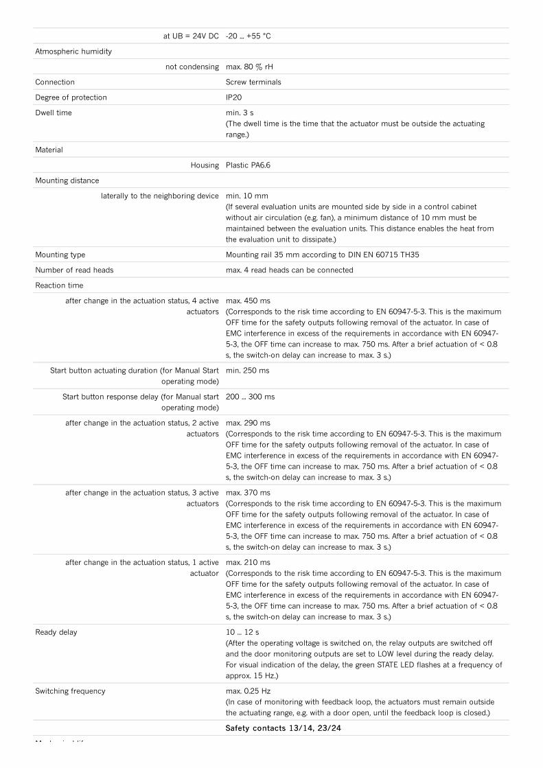
at UB = 24V DC -20 ... +55 °C
Atmospheric humidity
not condensing max. 80 % rH
Connection Screw terminals
Degree of protection IP20
Dwell time min. 3 s(The dwell time is the time that the actuator must be outside the actuatingrange.)
Material
Housing Plastic PA6.6
Mounting distance
laterally to the neighboring device min. 10 mm(If several evaluation units are mounted side by side in a control cabinetwithout air circulation (e.g. fan), a minimum distance of 10 mm must bemaintained between the evaluation units. This distance enables the heat fromthe evaluation unit to dissipate.)
Mounting type Mounting rail 35 mm according to DIN EN 60715 TH35
Number of read heads max. 4 read heads can be connected
Reaction time
after change in the actuation status, 4 activeactuators
max. 450 ms(Corresponds to the risk time according to EN 60947-5-3. This is the maximumOFF time for the safety outputs following removal of the actuator. In case ofEMC interference in excess of the requirements in accordance with EN 60947-5-3, the OFF time can increase to max. 750 ms. After a brief actuation of < 0.8s, the switch-on delay can increase to max. 3 s.)
Start button actuating duration (for Manual Startoperating mode)
min. 250 ms
Start button response delay (for Manual startoperating mode)
200 ... 300 ms
after change in the actuation status, 2 activeactuators
max. 290 ms(Corresponds to the risk time according to EN 60947-5-3. This is the maximumOFF time for the safety outputs following removal of the actuator. In case ofEMC interference in excess of the requirements in accordance with EN 60947-5-3, the OFF time can increase to max. 750 ms. After a brief actuation of < 0.8s, the switch-on delay can increase to max. 3 s.)
after change in the actuation status, 3 activeactuators
max. 370 ms(Corresponds to the risk time according to EN 60947-5-3. This is the maximumOFF time for the safety outputs following removal of the actuator. In case ofEMC interference in excess of the requirements in accordance with EN 60947-5-3, the OFF time can increase to max. 750 ms. After a brief actuation of < 0.8s, the switch-on delay can increase to max. 3 s.)
after change in the actuation status, 1 activeactuator
max. 210 ms(Corresponds to the risk time according to EN 60947-5-3. This is the maximumOFF time for the safety outputs following removal of the actuator. In case ofEMC interference in excess of the requirements in accordance with EN 60947-5-3, the OFF time can increase to max. 750 ms. After a brief actuation of < 0.8s, the switch-on delay can increase to max. 3 s.)
Ready delay 10 ... 12 s(After the operating voltage is switched on, the relay outputs are switched offand the door monitoring outputs are set to LOW level during the ready delay.For visual indication of the delay, the green STATE LED flashes at a frequency ofapprox. 15 Hz.)
Switching frequency max. 0.25 Hz(In case of monitoring with feedback loop, the actuators must remain outsidethe actuating range, e.g. with a door open, until the feedback loop is closed.)
Safety contacts 13/14, 23/24Safety contacts 13/14, 23/24
Mechanical life

Mechanical life
Schaltspiele (Relais) 10 x 10⁶Number of safety contacts 2 Relay with internally monitored contacts
Diagnostic Coverage (DC) 99 %
Mission time 20 y(This value is dependent on the number of switching cycles and the switchingcurrent.)
Number of switching cycles
≤ 0.1 A max. 760000 1/Jahr
≤ 1 A max. 153000 1/Jahr
≤ 3 A max. 34600 1/Jahr
Monitoring of the guard positionMonitoring of the guard position
Category 4(This value is dependent on the number of switching cycles and the switchingcurrent.)
Performance Level PL e(This value is dependent on the number of switching cycles and the switchingcurrent.)
PFHd 1.9 x 10(This value is dependent on the number of switching cycles and the switchingcurrent.)
Mounting distance
neighboring read heads min. 80 mm(If several evaluation units are mounted side by side in a control cabinetwithout air circulation (e.g. fan), a minimum distance of 10 mm must bemaintained between the evaluation units. This distance enables the heat fromthe evaluation unit to dissipate.)
Assured operating distance s
for vertical approach direction (center offset m=0) min. 16 mm(These values apply to surface installation of the read head and the actuator.)
for side approach direction (distance in x direction10 mm)
min. +/- 24 mm(These values apply to surface installation of the read head and the actuator.)
Assured release distance s max. 60 mm
Operating distance
for vertical approach direction (center offset m=0) 23 mm(These values apply to surface installation of the read head and the actuator.)
for side approach direction (distance in x direction10 mm)
+/- 28 mm(These values apply to surface installation of the read head and the actuator.)
Switching hysteresis
for vertical approach direction (center offset m=0) 2 ... 3 mm(These values apply to surface installation of the read head and the actuator.)
for side approach direction (distance in x direction10 mm)
1 ... 1.3 mm(These values apply to surface installation of the read head and the actuator.)
Reliability values according to EN ISO 13849-1Reliability values according to EN ISO 13849-1
-8
In combination with read head CES-A-LQA-SCIn combination with read head CES-A-LQA-SC
In combination with read head CES-A-LQA-SC and actuator CES-A-BQAIn combination with read head CES-A-LQA-SC and actuator CES-A-BQA
ao
ar
In combination with read head CES-A-LNN-SC-106601, CES-A-LNN-05V-106602, CES-A-LNN-10V-In combination with read head CES-A-LNN-SC-106601, CES-A-LNN-05V-106602, CES-A-LNN-10V-113294 and actuator CES-A-BDN-06-104730113294 and actuator CES-A-BDN-06-104730
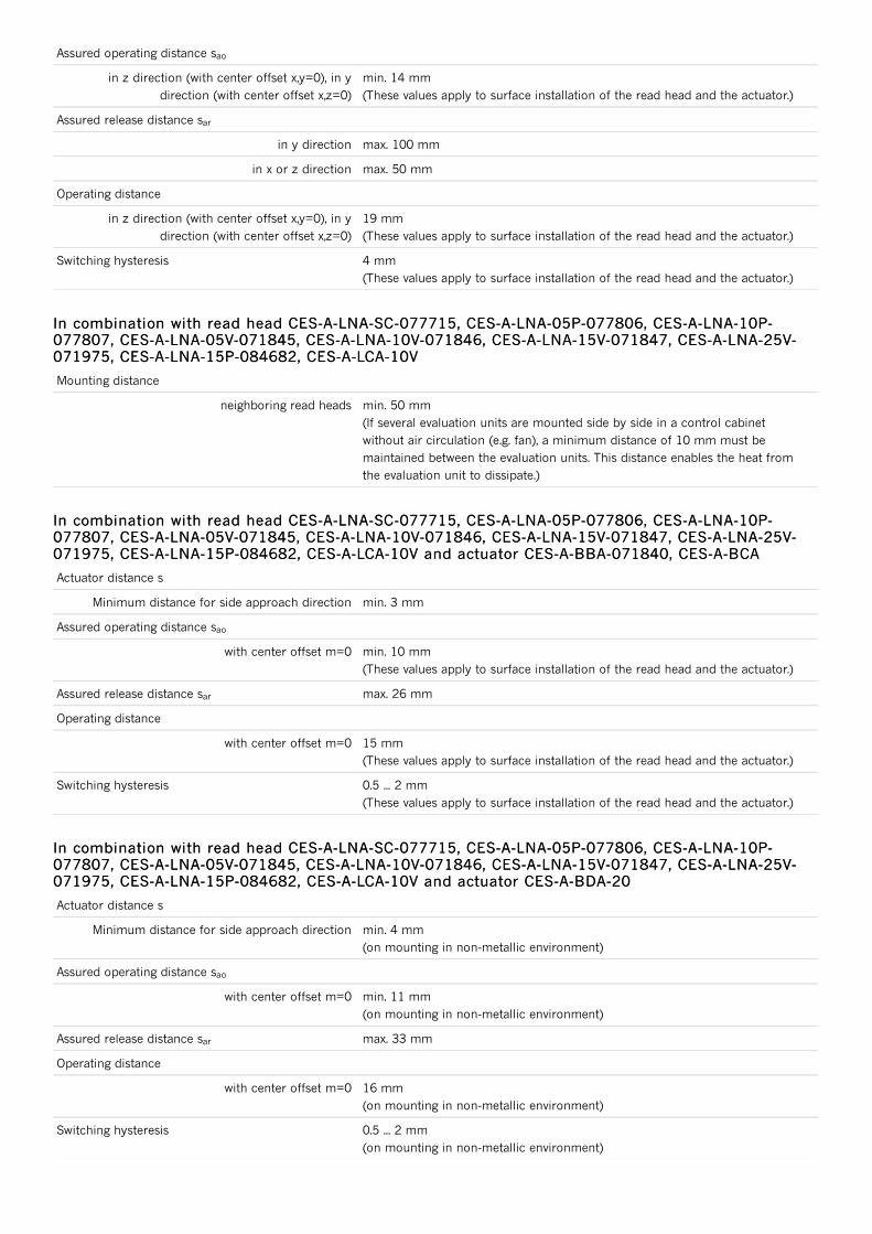
Assured operating distance s
in z direction (with center offset x,y=0), in ydirection (with center offset x,z=0)
min. 14 mm(These values apply to surface installation of the read head and the actuator.)
Assured release distance s
in y direction max. 100 mm
in x or z direction max. 50 mm
Operating distance
in z direction (with center offset x,y=0), in ydirection (with center offset x,z=0)
19 mm(These values apply to surface installation of the read head and the actuator.)
Switching hysteresis 4 mm(These values apply to surface installation of the read head and the actuator.)
Mounting distance
neighboring read heads min. 50 mm(If several evaluation units are mounted side by side in a control cabinetwithout air circulation (e.g. fan), a minimum distance of 10 mm must bemaintained between the evaluation units. This distance enables the heat fromthe evaluation unit to dissipate.)
Actuator distance s
Minimum distance for side approach direction min. 3 mm
Assured operating distance s
with center offset m=0 min. 10 mm(These values apply to surface installation of the read head and the actuator.)
Assured release distance s max. 26 mm
Operating distance
with center offset m=0 15 mm(These values apply to surface installation of the read head and the actuator.)
Switching hysteresis 0.5 ... 2 mm(These values apply to surface installation of the read head and the actuator.)
Actuator distance s
Minimum distance for side approach direction min. 4 mm(on mounting in non-metallic environment)
Assured operating distance s
with center offset m=0 min. 11 mm(on mounting in non-metallic environment)
Assured release distance s max. 33 mm
Operating distance
with center offset m=0 16 mm(on mounting in non-metallic environment)
Switching hysteresis 0.5 ... 2 mm(on mounting in non-metallic environment)
ao
ar
In combination with read head CES-A-LNA-SC-077715, CES-A-LNA-05P-077806, CES-A-LNA-10P-In combination with read head CES-A-LNA-SC-077715, CES-A-LNA-05P-077806, CES-A-LNA-10P-077807, CES-A-LNA-05V-071845, CES-A-LNA-10V-071846, CES-A-LNA-15V-071847, CES-A-LNA-25V-077807, CES-A-LNA-05V-071845, CES-A-LNA-10V-071846, CES-A-LNA-15V-071847, CES-A-LNA-25V-071975, CES-A-LNA-15P-084682, CES-A-LCA-10V071975, CES-A-LNA-15P-084682, CES-A-LCA-10V
In combination with read head CES-A-LNA-SC-077715, CES-A-LNA-05P-077806, CES-A-LNA-10P-In combination with read head CES-A-LNA-SC-077715, CES-A-LNA-05P-077806, CES-A-LNA-10P-077807, CES-A-LNA-05V-071845, CES-A-LNA-10V-071846, CES-A-LNA-15V-071847, CES-A-LNA-25V-077807, CES-A-LNA-05V-071845, CES-A-LNA-10V-071846, CES-A-LNA-15V-071847, CES-A-LNA-25V-071975, CES-A-LNA-15P-084682, CES-A-LCA-10V and actuator CES-A-BBA-071840, CES-A-BCA071975, CES-A-LNA-15P-084682, CES-A-LCA-10V and actuator CES-A-BBA-071840, CES-A-BCA
ao
ar
In combination with read head CES-A-LNA-SC-077715, CES-A-LNA-05P-077806, CES-A-LNA-10P-In combination with read head CES-A-LNA-SC-077715, CES-A-LNA-05P-077806, CES-A-LNA-10P-077807, CES-A-LNA-05V-071845, CES-A-LNA-10V-071846, CES-A-LNA-15V-071847, CES-A-LNA-25V-077807, CES-A-LNA-05V-071845, CES-A-LNA-10V-071846, CES-A-LNA-15V-071847, CES-A-LNA-25V-071975, CES-A-LNA-15P-084682, CES-A-LCA-10V and actuator CES-A-BDA-20071975, CES-A-LNA-15P-084682, CES-A-LCA-10V and actuator CES-A-BDA-20
ao
ar

Actuator distance s
Minimum distance for side approach direction min. 3 mm
Assured operating distance s
with center offset m=0 min. 6 mm(These values apply to surface installation of the read head and the actuator.)
Assured release distance s max. 21 mm
Operating distance
with center offset m=0 9 mm(These values apply to surface installation of the read head and the actuator.)
Switching hysteresis
with center offset m=0 0.5 ... 1 mm(These values apply to surface installation of the read head and the actuator.)
Assured operating distance s
for vertical approach direction (center offset m=0) min. 10 mm(These values apply to surface installation of the read head and the actuator.)
for side approach direction (distance in x direction 8mm)
min. +/- 18 mm(These values apply to surface installation of the read head and the actuator.)
Assured release distance s max. 47 mm
Operating distance
for vertical approach direction (center offset m=0) 15 mm(These values apply to surface installation of the read head and the actuator.)
for side approach direction (distance in x direction 8mm)
+/- 22 mm(These values apply to surface installation of the read head and the actuator.)
Switching hysteresis
for vertical approach direction (center offset m=0) 2 ... 3 mm(These values apply to surface installation of the read head and the actuator.)
for side approach direction (distance in x direction 8mm)
1 ... 1.8 mm(These values apply to surface installation of the read head and the actuator.)
Assured operating distance s
in z direction (with center offset x,y=0), in ydirection (with center offset x,z=0)
min. 10 mm(These values apply to surface installation of the read head and the actuator.)
Assured release distance s
in y direction max. 100 mm
in x or z direction max. 50 mm
Operating distance
in z direction (with center offset x,y=0), in ydirection (with center offset x,z=0)
15 mm(These values apply to surface installation of the read head and the actuator.)
Switching hysteresis 1 ... 4 mm(These values apply to surface installation of the read head and the actuator.)
In combination with read head CES-A-LMN-SC and actuator CES-A-BDA-18-156935In combination with read head CES-A-LMN-SC and actuator CES-A-BDA-18-156935
ao
ar
In combination with read head CES-A-LQA-SC and actuator CES-A-BBA-071840, CES-A-BCAIn combination with read head CES-A-LQA-SC and actuator CES-A-BBA-071840, CES-A-BCA
ao
ar
In combination with read head CES-A-LNN-SC-106601, CES-A-LNN-05V-106602, CES-A-LNN-10V-In combination with read head CES-A-LNN-SC-106601, CES-A-LNN-05V-106602, CES-A-LNN-10V-113294 and actuator CES-A-BBN-106600113294 and actuator CES-A-BBN-106600
ao
ar
In combination with read head CES-A-LNA-SC-077715, CES-A-LNA-05P-077806, CES-A-LNA-10P-In combination with read head CES-A-LNA-SC-077715, CES-A-LNA-05P-077806, CES-A-LNA-10P-077807, CES-A-LNA-05V-071845, CES-A-LNA-10V-071846, CES-A-LNA-15V-071847, CES-A-LNA-25V-077807, CES-A-LNA-05V-071845, CES-A-LNA-10V-071846, CES-A-LNA-15V-071847, CES-A-LNA-25V-071975, CES-A-LNA-15P-084682, CES-A-LCA-10V and actuator CES-A-BDA-18-156935071975, CES-A-LNA-15P-084682, CES-A-LCA-10V and actuator CES-A-BDA-18-156935

Actuator distance s
Minimum distance for side approach direction min. 5 mm
Assured operating distance s
with center offset m=0 min. 10 mm(These values apply to surface installation of the read head and the actuator.)
Assured release distance s max. 32 mm
Operating distance
with center offset m=0 16 mm(These values apply to surface installation of the read head and the actuator.)
Switching hysteresis
with center offset m=0 0.5 ... 1.4 mm(These values apply to surface installation of the read head and the actuator.)
Mounting distance
neighboring read heads min. 20 mm(If several evaluation units are mounted side by side in a control cabinetwithout air circulation (e.g. fan), a minimum distance of 10 mm must bemaintained between the evaluation units. This distance enables the heat fromthe evaluation unit to dissipate.)
Assured operating distance s
with center offset m=0 min. 5 mm(This value applies to surface installation of the read head in metal and non-metallic installation of the actuator.)
Assured release distance s
with center offset m=0 max. 25 mm(This value applies to surface installation of the read head in metal and non-metallic installation of the actuator.)
Operating distance
with center offset m=0 8 mm A distance of s = 3 mm must be maintained for a side approachdirection.(This value applies to surface installation of the read head in metal and non-metallic installation of the actuator.)
Switching hysteresis
with center offset m=0 1 ... 1.8 mm(These values apply to surface installation of the read head in metal and non-metallic installation of the actuator.)
Actuator distance s
Minimum distance min. 1.2 mm
Assured operating distance s
with center offset m=0 min. 3.5 mm(These values apply to surface installation of the read head in steel.)
Assured release distance s max. 10 mm
Operating distance
with center offset m=0 5 mm(These values apply to surface installation of the read head in steel.)
Switching hysteresis 0.1 ... 0.3 mm(These values apply to surface installation of the read head in steel.)
ao
ar
In combination with read head CES-A-LMN-SCIn combination with read head CES-A-LMN-SC
In combination with read head CES-A-LMN-SC and actuator CES-A-BBA-071840In combination with read head CES-A-LMN-SC and actuator CES-A-BBA-071840
ao
ar
In combination with read head CES-A-LMN-SC and actuator CES-A-BMBIn combination with read head CES-A-LMN-SC and actuator CES-A-BMB
ao
ar
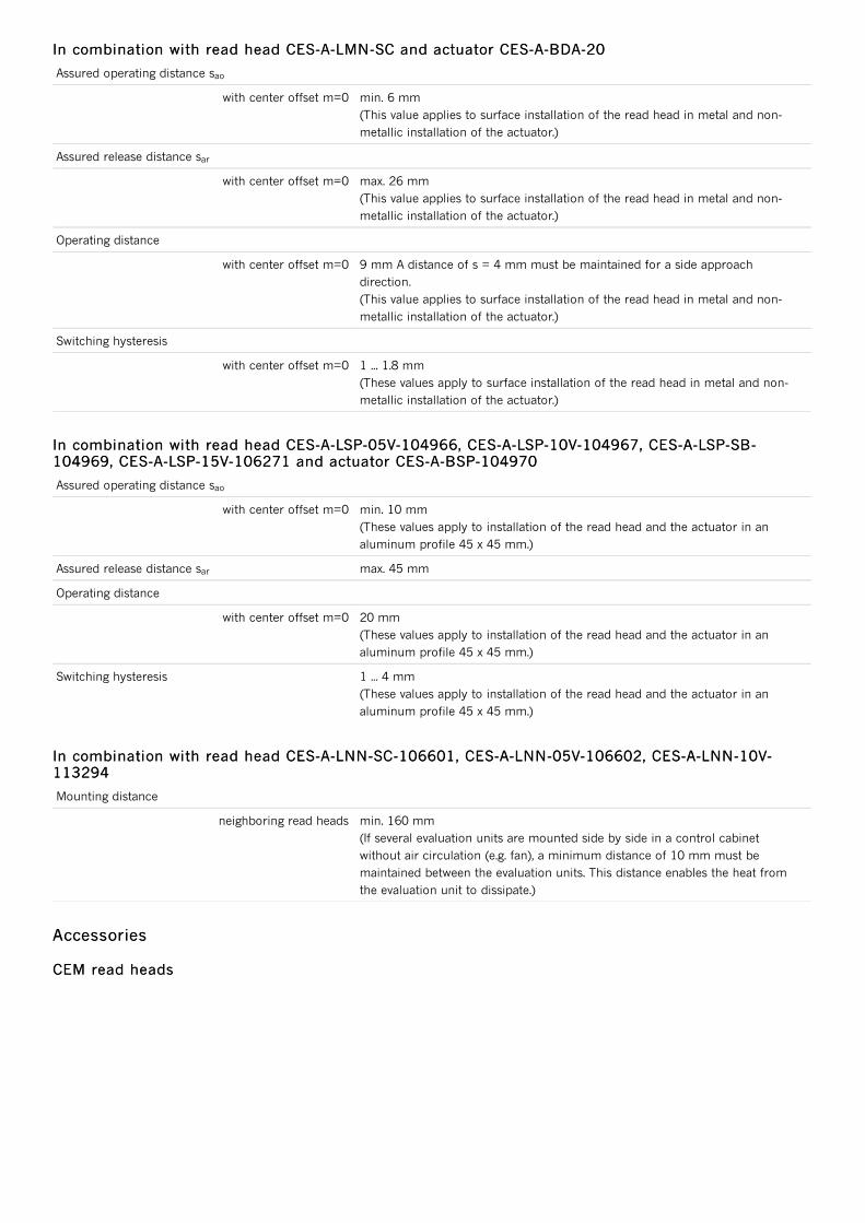
Assured operating distance s
with center offset m=0 min. 6 mm(This value applies to surface installation of the read head in metal and non-metallic installation of the actuator.)
Assured release distance s
with center offset m=0 max. 26 mm(This value applies to surface installation of the read head in metal and non-metallic installation of the actuator.)
Operating distance
with center offset m=0 9 mm A distance of s = 4 mm must be maintained for a side approachdirection.(This value applies to surface installation of the read head in metal and non-metallic installation of the actuator.)
Switching hysteresis
with center offset m=0 1 ... 1.8 mm(These values apply to surface installation of the read head in metal and non-metallic installation of the actuator.)
Assured operating distance s
with center offset m=0 min. 10 mm(These values apply to installation of the read head and the actuator in analuminum profile 45 x 45 mm.)
Assured release distance s max. 45 mm
Operating distance
with center offset m=0 20 mm(These values apply to installation of the read head and the actuator in analuminum profile 45 x 45 mm.)
Switching hysteresis 1 ... 4 mm(These values apply to installation of the read head and the actuator in analuminum profile 45 x 45 mm.)
Mounting distance
neighboring read heads min. 160 mm(If several evaluation units are mounted side by side in a control cabinetwithout air circulation (e.g. fan), a minimum distance of 10 mm must bemaintained between the evaluation units. This distance enables the heat fromthe evaluation unit to dissipate.)
In combination with read head CES-A-LMN-SC and actuator CES-A-BDA-20In combination with read head CES-A-LMN-SC and actuator CES-A-BDA-20
ao
ar
In combination with read head CES-A-LSP-05V-104966, CES-A-LSP-10V-104967, CES-A-LSP-SB-In combination with read head CES-A-LSP-05V-104966, CES-A-LSP-10V-104967, CES-A-LSP-SB-104969, CES-A-LSP-15V-106271 and actuator CES-A-BSP-104970104969, CES-A-LSP-15V-106271 and actuator CES-A-BSP-104970
ao
ar
In combination with read head CES-A-LNN-SC-106601, CES-A-LNN-05V-106602, CES-A-LNN-10V-In combination with read head CES-A-LNN-SC-106601, CES-A-LNN-05V-106602, CES-A-LNN-10V-113294113294
AccessoriesAccessories
CEM read headsCEM read heads

Read head CEM-A-LE05... with guard locking without guard lock monitoring with remanenceRead head CEM-A-LE05... with guard locking without guard lock monitoring with remanence
094800094800CEM-A-LE05K-S2
Read head with guard locking without
guard lock monitoring
Locking force 650 N
With remanence
Up to category 4 according to EN ISO
13849-1
Two safety screws M5x16 included
102821102821CEM-A-LE05K-S1-10P
Read head with guard locking without
guard lock monitoring
Locking force 650 N
With remanence
With connecting cable 10 m, PUR, for
connection to the CES evaluation unit
Up to category 4 according to EN ISO
13849-1
Two safety screws M5x16 included
Read head CEM-A-LE05... with guard locking without guard lock monitoring without remanenceRead head CEM-A-LE05... with guard locking without guard lock monitoring without remanence
095792095792CEM-A-LE05R-S2
Read head with guard locking without
guard lock monitoring
Locking force 650 N
Without remanence
Up to category 4 according to EN ISO
13849-1
Two safety screws M5x16 included
Read head CEM-A-LH10K-S3 with guard locking without guard lock monitoring with remanenceRead head CEM-A-LH10K-S3 with guard locking without guard lock monitoring with remanence
095170095170CEM-A-LH10K-S3
Read head with guard locking without
guard lock monitoring
Locking force 1000 N
With remanence
Up to category 4 according to EN ISO
13849-1
Read head CEM-A-LH10R-S3 with guard locking without guard lock monitoring without remanenceRead head CEM-A-LH10R-S3 with guard locking without guard lock monitoring without remanence
095793095793CEM-A-LH10R-S3
Read head with guard locking without
guard lock monitoring
Locking force 1000 N
Without remanence
Up to category 4 according to EN ISO
13849-1
CES read headsCES read heads
Read head CES-A-LCA..., hard-wired encapsulated cable 10 m, PVCRead head CES-A-LCA..., hard-wired encapsulated cable 10 m, PVC
088785088785CES-A-LCA-10V
Cube-shaped design 42 x 25 mm
Hard-wired encapsulated cable made of
PVC
Cable length 10 m
Two safety screws M4x14 included
Read head CES-A-LMN-SC, M8 plug connectorRead head CES-A-LMN-SC, M8 plug connector
077790077790CES-A-LMN-SC
Cylindrical design M12
M8 plug connector

Read head CES-A-LNA-SC, M8 plug connectorRead head CES-A-LNA-SC, M8 plug connector
077715077715CES-A-LNA-SC-077715
Cube-shaped design 42 x 25 mm
With plug connector M8
Two safety screws M4x14 included
Read head CES-A-LNA..., hard-wired encapsulated cable 10 m, PURRead head CES-A-LNA..., hard-wired encapsulated cable 10 m, PUR
077807077807CES-A-LNA-10P-077807
Cube-shaped design 42 x 25 mm
Hard-wired encapsulated cable made of
PUR
Cable length 10 m
Two safety screws M4x14 included
Read head CES-A-LNA..., hard-wired encapsulated cable 10 m, PVCRead head CES-A-LNA..., hard-wired encapsulated cable 10 m, PVC
071846071846CES-A-LNA-10V-071846
Cube-shaped design 42 x 25 mm
Hard-wired encapsulated cable made of
PVC
Cable length 10 m
Two safety screws M4x14 included
Read head CES-A-LNA..., hard-wired encapsulated cable 15 m, PURRead head CES-A-LNA..., hard-wired encapsulated cable 15 m, PUR
084682084682CES-A-LNA-15P-084682
Cube-shaped design 42 x 25 mm
Hard-wired encapsulated cable made of
PUR
Cable length 15 m
Two safety screws M4x14 included
Read head CES-A-LNA..., hard-wired encapsulated cable 15 m, PVCRead head CES-A-LNA..., hard-wired encapsulated cable 15 m, PVC
071847071847CES-A-LNA-15V-071847
Cube-shaped design 42 x 25 mm
Hard-wired encapsulated cable made of
PVC
Cable length 15 m
Two safety screws M4x14 included
Read head CES-A-LNA..., hard-wired encapsulated cable 25 m, PVCRead head CES-A-LNA..., hard-wired encapsulated cable 25 m, PVC
071975071975CES-A-LNA-25V-071975
Cube-shaped design 42 x 25 mm
Hard-wired encapsulated cable made of
PVC
Cable length 25 m
Two safety screws M4x14 included
Read head CES-A-LNA..., hard-wired encapsulated cable 5 m, PURRead head CES-A-LNA..., hard-wired encapsulated cable 5 m, PUR
077806077806CES-A-LNA-05P-077806
Cube-shaped design 42 x 25 mm
Hard-wired encapsulated cable made of
PUR
Cable length 5 m
Two safety screws M4x14 included
Read head CES-A-LNA..., hard-wired encapsulated cable 5 m, PVCRead head CES-A-LNA..., hard-wired encapsulated cable 5 m, PVC
071845071845 Cube-shaped design 42 x 25 mm

071845071845CES-A-LNA-05V-071845
Cube-shaped design 42 x 25 mm
Hard-wired encapsulated cable made of
PVC
Cable length 5 m
Two safety screws M4x14 included
Read head CES-A-LNN-...hard-wired encapsulated cable 5 m, PVCRead head CES-A-LNN-...hard-wired encapsulated cable 5 m, PVC
106602106602CES-A-LNN-05V-106602
Cube-shaped design 42 x 25 mm
Mounting compatible with series CES-A-
LNA/LCA
LED for indicating the door position
Hard-wired encapsulated cable, PVC
Cable length 5 m
Read head CES-A-LNN-SC... M8 plug connectorRead head CES-A-LNN-SC... M8 plug connector
106601106601CES-A-LNN-SC-106601
Cube-shaped design 42 x 25 mm
Mounting compatible with series CES-A-
LNA/LCA
LED for indicating the door position
With plug connector M8
Read head CES-A-LQA-SC, M8 plug connectorRead head CES-A-LQA-SC, M8 plug connector
095650095650CES-A-LQA-SC
Cube-shaped design 50 x 50 mm
M8 plug connector
Two safety screws M4x14 included
Read head CES-A-LSP-..., hard-wired encapsulated cable, 5 m, PVCRead head CES-A-LSP-..., hard-wired encapsulated cable, 5 m, PVC
104966104966CES-A-LSP-05V-104966
Optimized for aluminum profile mounting
LED for indicating the door position
Hard-wired encapsulated cable made of
PVC
Cable length 5 m
CET-AX read headsCET-AX read heads

Read head CET1-AX-... M12, with guard locking and guard lock monitoring, 2 freely configurableRead head CET1-AX-... M12, with guard locking and guard lock monitoring, 2 freely configurableLEDsLEDs
104062104062CET1-AX-LRA-00-50L-SA
Read head with guard locking
Locking force up to 6,500 N
Up to category 4 / PL e according to EN
ISO 13849-1
With plug connector M12
2 LEDs (2 freely configurable)
Approach direction A (delivery state)
Read head CET1-AX-... M12, with guard locking and guard lock monitoring, double rampRead head CET1-AX-... M12, with guard locking and guard lock monitoring, double ramp
100399100399CET1-AX-LDA-00-50X-SE
Read head with guard locking
Locking force up to 6,500 N
Up to category 4 / PL e according to EN
ISO 13849-1
With plug connector M12
2 LEDs (1 freely configurable)
With double ramp
Approach directions A and C (delivery
state)
Read head CET1-AX-... M12, with guard locking and guard lock monitoring, escape releaseRead head CET1-AX-... M12, with guard locking and guard lock monitoring, escape release
102161102161CET1-AX-LRA-00-50F-SA
Read head with guard locking
Locking force up to 6,500 N
Up to category 4 / PL e according to EN
ISO 13849-1
With plug connector M12
2 LEDs (1 freely configurable)
With escape release, 75 mm long
Approach direction A (delivery state)
Read head CET1-AX-..., 2 plug connectors M8, with guard locking and guard lock monitoringRead head CET1-AX-..., 2 plug connectors M8, with guard locking and guard lock monitoring
102988102988CET1-AX-LRA-00-50X-SC
Read head with guard locking
Locking force up to 6,500 N
Up to category 4 / PL e according to EN
ISO 13849-1
With 2 plug connectors M8
2 LEDs (1 freely configurable)
Approach direction A (delivery state)
Read head CET1-AX-..., M12, with guard locking and guard lock monitoringRead head CET1-AX-..., M12, with guard locking and guard lock monitoring
095735095735CET1-AX-LRA-00-50X-SA
Read head with guard locking
Locking force up to 6,500 N
Up to category 4 / PL e according to EN
ISO 13849-1
With plug connector M12
2 LEDs (1 freely configurable)
Approach direction A (delivery state)
CKSCKS

Key adapter CKSKey adapter CKS
113130113130CKS-A-L1B-SC-113130
Key adapter with integrated CES read
head
Suitable for connection to a CES-AZ
evaluation unit or CES-FD field unit
Simple connection via plug connector M8
Front cover: red
High degree of protection IP67
LED indicator
158081158081CKS-A-L1B-SC-158081
Key adapter with integrated CES read
head
Suitable for connection to a CES-AZ
evaluation unit or CES-FD field unit
Simple connection via plug connector M8
Front cover: black
High degree of protection IP67
LED indicator
Connection materialConnection material
Connection kit for evaluation units CES-AZ-.ES-04B and CES-AR-AES-12, screw terminalsConnection kit for evaluation units CES-AZ-.ES-04B and CES-AR-AES-12, screw terminals
104776104776CES-EA-TC-AK08-104776
Plug-in screw terminals for evaluation
units CES-AZ-.ES-04B and CES-AR-AES-
12
Coded
Connection kit for evaluation units CES-AZ-.ES-04B and CES-AR-AES-12, spring terminalsConnection kit for evaluation units CES-AZ-.ES-04B and CES-AR-AES-12, spring terminals
112629112629CES-EA-TC-KK08-112629
Plug-in spring terminals for evaluation
units CES-AZ-.ES-04B and CES-AR-AES-
12
Coded
MiscellaneousMiscellaneous
Inrush current limiting module PM-SCLInrush current limiting module PM-SCL
096945096945PM-SCL-096945
Limitation of switch-on current
Suitable for mounting on mounting rail
EUCHNER GmbH + Co. KG
Kohlhammerstraße 16
70771 Leinfelden-Echterdingen
+49 711 7597-0
+49 711 753316
info(at)euchner.de
ContactsContacts
