ch series application drawings - blueridge...
TRANSCRIPT

These drawing are intended as a guide only and not as a replacement for professionally engineered project drawings. These concept system drawings do not imply compliance with local building codes. Actual installations may vary depending on installation location & parameters and it must be done in accordance with all local building codes. Verify with local building o�cials before commencement of system installations.
Guide Only
CH Series Application Drawings
20 GoodyearIrvine, CA 92618
800-519-8794www.NavienAmerica.com
CH-240ASME
Ele
ct.W
ater
Feed
NAVIENCH
Combi
BoilerS R
DomesticH C
CH-210ASMEE
lect
.Wat
erFe
ed
NAVIENCH
Combi
BoilerS R
DomesticH C
CH-180ASME
Ele
ct.W
ater
Feed
NAVIENCH
Combi
BoilerS R
DomesticH C
T
Check Valve Circulator
PressureReliefValve
ExpansionTank
Aquastat
Full-portBall Valve
MixingValve
DHW Circulatorw/Aquastat & Check Valve
BackflowPreventor
AirElimination

20 Goodyear
Irvine, CA 92618
800-519-8794
www.navienamerica.com
T
Check Valve Circulator
Drawn By: B. Fenske October 25, 2011
Pressure
Relief
ValveExpansion
Tank
Thermostat
Full-port
Ball Valve
Mixing
Valve
Air
Elimination
DHW Circulator
w/Aquastat & Check Valve
This drawing is intended only as a guide and not as a replacement for professionally engineered project drawings.
This concept system drawing does not imply compliance with local building codes. Actual installation may vary
depending on installation location & parameters and it must be done in accordance to all local building codes.
Verify with local building officials before commencement of system installation.
Backflow
PreventerCH-BF01E
lect. W
ate
r F
eed
NAVIEN
CH
Combi
Boiler
S R
Domestic
H C
Gas
Hydronic
Feed Water
Domestic
Water
Navien CH Combi Boiler Application
Typical Piping Diagram with Three
Zone Options Shown
Multiple Returns
Heating
System
Return
Heating
System
Supply Min 6"
Multiple Zones
By Circulators
Multiple Zones
By Zone Valves
w/System Circulator
System circulator, zone circulators & zone valves sizes and
performance are selected by installing contractor or engineer to
meet heat emitter/structure heat loss requirements
Circulator
Zone Panel
TTT
T
Circulator
Zone Panel
Circulator
Zone Panel
T T T
120 to 24VAC
Transformer
A
C
B
Single Zone
1 System Circulator
Multiple Zones
By Circulators
Multiple Zones
By Zone Valves
With System Circulator
A
B
C
Field Supplied Circulator Panels Shall have Dry
Contacts Closed On Heat Calls Wired to Navien CH
Unit “R & W” Terminals To Activate Heat Mode
Options Shown:
1
11
1
Cold
Hot
To CH Unit
Terminal Strip
“R + W” *
DIP SW
#3 of 8 UP

20 Goodyear
Irvine, CA 92618
800-519-8794
www.navienamerica.com
T
Check Valve Circulator
Drawn By: B. Fenske June 26, 2012
Pressure
Relief
ValveExpansion
Tank
Aquastat
Full-port
Ball Valve
Mixing
Valve
DHW Circulator
w/Aquastat & Check Valve
This drawing is intended only as a guide and not as a replacement for professionally engineered project drawings.
This concept system drawing does not imply compliance with local building codes. Actual installation may vary
depending on installation location & parameters and it must be done in accordance to all local building codes.
Verify with local building officials before commencement of system installation.
Backflow
PreventorCH-BF-CHQuik1
Ele
ct.
Wa
ter
Fe
ed
NAVIEN
CH
Combi
Boiler
S R
Domestic
H C
Gas
Hydronic
Feed Water
Cold Domestic
Hot Domestic
Navien CH Combi Boiler
With CH Quik-Install Manifold Kit
Single System Circulator Shown
T
Circ
Panel
Field Supplied Circulator Zone Panel
Shall have Dry Contacts Closed On Heat
Calls Wired to Navien CH Unit “R & W”
Terminals To Activate Heat Mode
DIP Sw 3 of 8 Up (ON)
Air
Elimination

20 Goodyear
Irvine, CA 92618
800-519-8794
www.navienamerica.com
T
Check Valve Circulator
Drawn By: B. Fenske June 26. 2012
Pressure
Relief
ValveExpansion
Tank
Aquastat
Full-port
Ball Valve
Mixing
Valve
Air
Elimination
DHW Circulator
w/Aquastat & Check Valve
This drawing is intended only as a guide and not as a replacement for professionally engineered project drawings.
This concept system drawing does not imply compliance with local building codes. Actual installation may vary
depending on installation location & parameters and it must be done in accordance to all local building codes.
Verify with local building officials before commencement of system installation.
Backflow
Preventor
Ele
ct.
Wa
ter
Fe
ed
NAVIEN
CH
Combi
Boiler
S R
Domestic
H C
Gas
Hydronic
Feed Water
Cold Domestic
Hot Domestic
Circ Zone
Panel
T T T
Navien CH Combi Boiler
With CH Quik-Install Manifold Kit
Multiple System Circulators Shown
CH-BF-CHQuik2
Field Supplied Circulator Zone Panel
Shall have Dry Contacts Closed On Heat
Calls Wired to Navien CH Unit “R & W”
Terminals To Activate Heat Mode
DIP Sw 3 of 8 Up (ON)
20 Goodyear
Irvine, CA 92618
800-519-8794
www.navienamerica.com
T
Check Valve Circulator
Drawn By: B. Fenske June 26, 2012
Pressure
Relief
ValveExpansion
Tank
Aquastat
Full-port
Ball Valve
Zone
Valve
DHW Circulator
w/Aquastat & Check Valve
This drawing is intended only as a guide and not as a replacement for professionally engineered project drawings.
This concept system drawing does not imply compliance with local building codes. Actual installation may vary
depending on installation location & parameters and it must be done in accordance to all local building codes.
Verify with local building officials before commencement of system installation.
Backflow
Preventor
Ele
ct.
Wa
ter
Fe
ed
NAVIEN
CH
Combi
Boiler
S R
Domestic
H C
Gas
Hydronic
Feed Water
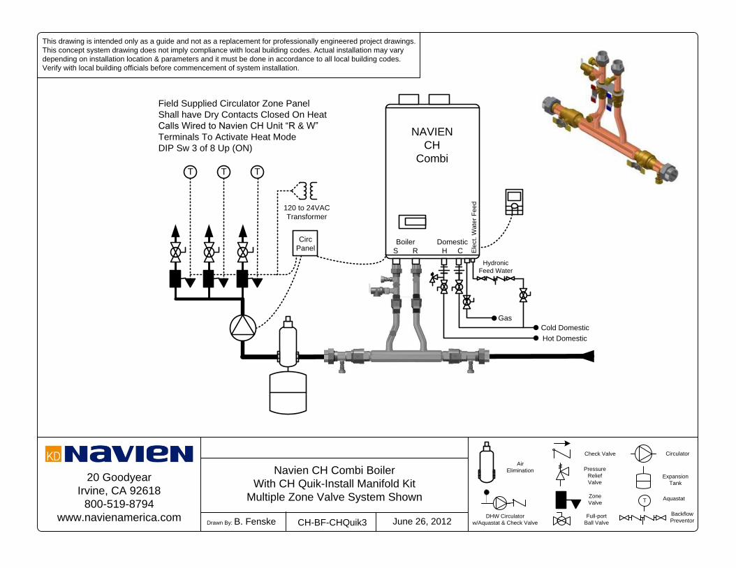
Cold Domestic
Hot Domestic
Circ
Panel
T T T
120 to 24VAC
Transformer
Navien CH Combi Boiler
With CH Quik-Install Manifold Kit
Multiple Zone Valve System Shown
CH-BF-CHQuik3
Field Supplied Circulator Zone Panel
Shall have Dry Contacts Closed On Heat
Calls Wired to Navien CH Unit “R & W”
Terminals To Activate Heat Mode
DIP Sw 3 of 8 Up (ON)
Air
Elimination

20 Goodyear
Irvine, CA 92618
800-519-8794
www.navienamerica.com
T
Check Valve Circulator
Drawn By: B. Fenske December 3, 2011
Pressure
Relief
ValveExpansion
Tank
Thermostat
Full-port
Ball Valve
Mixing
Valve
DHW Circulator
w/Aquastat & Check Valve
This drawing is intended only as a guide and not as a replacement for professionally engineered project drawings.
This concept system drawing does not imply compliance with local building codes. Actual installation may vary
depending on installation location & parameters and it must be done in accordance to all local building codes.
Verify with local building officials before commencement of system installation.
Backflow
PreventerCH-BF01-3RZ
Ele
ct. W
ate
r F
eed
NAVIEN
CH
Combi
Boiler
S RDomestic
H C
Gas
Hydronic
Feed Water
Domestic
Water
Navien CH Combi Boiler Application
Typical Piping Diagram with Three
Radiant Zones Shown
Heating
System
Return
Heating
System
Supply
System circulator, zone
circulators & zone valves sizes
and performance are selected
by installing contractor or
engineer to meet heat emitter/
structure heat loss requirements
TTT Field Supplied Circulator Zone Panels
Shall have Dry Contacts Closed On Heat
Calls Wired to Navien CH Unit “R & W”
Terminals To Activate Heat Mode
A
A
Cold
Hot
6"
Minimum
Air
Elimination

20 Goodyear
Irvine, CA 92618
800-519-8794
www.navienamerica.com
T
Check Valve Circulator
Drawn By: B. Fenske November 29, 2011
Pressure
Relief
ValveExpansion
Tank
Thermostat
Full-port
Ball Valve
Mixing
Valve
DHW Circulator
w/Aquastat & Check Valve
This drawing is intended only as a guide and not as a replacement for professionally engineered project drawings.
This concept system drawing does not imply compliance with local building codes. Actual installation may vary
depending on installation location & parameters and it must be done in accordance to all local building codes.
Verify with local building officials before commencement of system installation.
Backflow
PreventerCH-BF01-DHWC
Ele
ct. W
ate
r F
eed
NAVIEN
CH
Combi
Boiler
S R
Domestic
H C
Gas
Hydronic
Feed Water
Domestic
Water
Navien CH Combi Boiler Application
Typical Piping Diagram with Domestic Hot
Water Recirculation
Heating
System
Return(s)
Heating
System
Supply
Min 6"
System circulator, zone circulators &
zone valves, domestic hot water
circulator performance and sizes are
selected by installing contractor or
engineer to meet heat emitter/structure
heat loss requirements and building
piping variables.
T Circulator
Zone Panel
Field Supplied Circulator Panels Shall
have Dry Contacts Closed On Heat
Calls Wired to Navien CH Unit “R &
W” Terminals To Activate Heat Mode
(DIP SW 3 of 8 ON)
1
Cold
Hot
Fixtures
DHW Circulator Requirements:
1. S.S. or Bronze Body & Impeller
* DHW Side 2.5 PSI Pressure drop @ 2 GPM
2. > 0.5 GPM to Activate Burner
3. Maximum 2 GPM
4. Programmable Timer
5. Selectable Aquastat
* Set minimum 10°F below CH DHW Setpoint
*
Air
Elimination
Min 45 psi12 psi

20 Goodyear
Irvine, CA 92618
800-519-8794
www.navienamerica.com
Check Valve Circulator
Drawn By: B. Fenske October 31, 2012
Pressure
Relief
ValveExpansion
Tank
Solenoid
Full-port
Ball Valve
Mixing
Valve
DHW Circulator
w/Aquastat & Check Valve
This drawing is intended only as a guide and not as a replacement for professionally engineered project drawings.
This concept system drawing does not imply compliance with local building codes. Actual installation may vary
depending on installation location & parameters and it must be done in accordance to all local building codes.
Verify with local building officials before commencement of system installation.
Backflow
PreventorCH-BF-CHQuik1-NR-NP
Navien CH Combi Boiler
With CH Quik-Install Manifold Kit
Single System Circulator Shown
With Cascaded NR/NP
(A) Field Supplied Circulator Zone Panel
Shall have Dry Contacts Closed On Heat
Calls Wired to Navien CH Unit “R & W”
Terminals To Activate Heat Mode
DIP Sw 3 of 8 Up (ON).
(B) Refer to Navien Technical Bulletin:
#2012-A-008
Air
Elimination
Ele
ct. W
ate
r F
eed
Navien
CH
Combi
Unit
Boiler
S R
Domestic
H C
Hydronic
Feed Water
Cold Domestic
Hot Domestic
T
Circ
Panel
Gas Supply
Navien
NR/NP
Unit
ColdHot Gas
Optional Domestic Recirculation
(A)
Communication Cable
(B)
Heating System ReturnHeating System Supply

20 Goodyear
Irvine, CA 92618
800-519-8794
www.navienamerica.com
T
Check Valve Circulator
Drawn By: B. Fenske October 26, 2011
Pressure
Relief
ValveExpansion
Tank
Thermostat
Full-port
Ball Valve
Mixing
Valve
DHW Circulator
w/Aquastat & Check Valve
This drawing is intended only as a guide and not as a replacement for professionally engineered project drawings.
This concept system drawing does not imply compliance with local building codes. Actual installation may vary
depending on installation location & parameters and it must be done in accordance to all local building codes.
Verify with local building officials before commencement of system installation.
Backflow
PreventerCH – ST - BF01
Ele
ct. W
ate
r F
eed
NAVIEN
CH
Combi
Boiler
S R
Domestic
H C
Gas
Hydronic
Feed Water
Domestic
Water
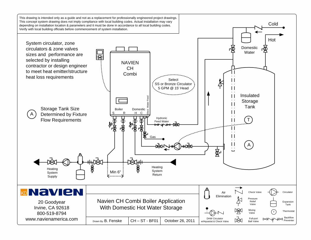
Navien CH Combi Boiler Application
With Domestic Hot Water Storage
Heating
System
Return
Heating
System
Supply
Min 6"
System circulator, zone
circulators & zone valves
sizes and performance are
selected by installing
contractor or design engineer
to meet heat emitter/structure
heat loss requirements
Cold
Hot
Insulated
Storage
Tank
T
Select
SS or Bronze Circulator
5 GPM @ 15' Head
A
AStorage Tank Size
Determined by Fixture
Flow Requirements
Air
Elimination
20 Goodyear
Irvine, CA 92618
800-519-8794
www.navienamerica.com
T
Check Valve Circulator
Drawn By: B. Fenske October 14, 2011
Pressure
Relief
ValveExpansion
Tank
Aquastat
Full-port
Ball Valve
Mixing
Valve
DHW Circulator
w/Aquastat & Check Valve
This drawing is intended only as a guide and not as a replacement for professionally engineered project drawings.
This concept system drawing does not imply compliance with local building codes. Actual installation may vary
depending on installation location & parameters and it must be done in accordance to all local building codes.
Verify with local building officials before commencement of system installation.
Backflow
PreventorCH-AH-BF01
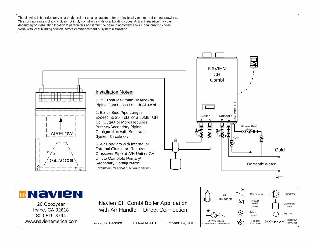
Navien CH Combi Boiler Application
with Air Handler - Direct Connection
Domestic Water
Hot
Cold
Installation Notes:
1. 25' Total Maximum Boiler-Side
Piping Connection Length Allowed.
2. Boiler-Side Pipe Length
Exceeding 25' Total or a 50MBTUH
Coil Output or More Requires
Primary/Secondary Piping
Configuration with Separate
System Circulator.
3. Air Handlers with Internal or
External Circulator Requires
Crossover Pipe at A/H Unit or CH
Unit to Complete Primary/
Secondary Configuration.
(Circulators must not function in series)
Ele
ct. W
ate
r F
eed
NAVIEN
CH
Combi
Boiler
S R
Domestic
H C
Gas
Hydronic Feed
Water
AIRFLOW
Opt. AC COIL
Air
Elimination

20 Goodyear
Irvine, CA 92618
800-519-8794
www.navienamerica.com
T
Check Valve Circulator
Drawn By: B. Fenske October 14, 2011
Pressure
Relief
ValveExpansion
Tank
Aquastat
Full-port
Ball Valve
Mixing
Valve
DHW Circulator
w/Aquastat & Check Valve
This drawing is intended only as a guide and not as a replacement for professionally engineered project drawings.
This concept system drawing does not imply compliance with local building codes. Actual installation may vary
depending on installation location & parameters and it must be done in accordance to all local building codes.
Verify with local building officials before commencement of system installation.
Backflow
PreventorCH-AH-BF02
Navien CH Combi Boiler Application
with Air Handler and A/H Internal Pump
Domestic Water
Hot
Cold
Installation Notes:
1. 100' Total Maximum Boiler-Side
Piping Connection Length Allowed.
2. Boiler-Side Pipe Length
Exceeding 100' Total or a
75MBTUH Coil Output or More
Requires Primary/Secondary Piping
Configuration with A/H connection
the tertiary secondary.
Ele
ct. W
ate
r F
eed
NAVIEN
CH
Combi
Boiler
S R
Domestic
H C
Gas
Hydronic Feed
Water
AIRFLOW
Opt. AC COIL
Air
Elimination

20 Goodyear
Irvine, CA 92618
800-519-8794
www.navienamerica.com
T
Check Valve Circulator
Drawn By: B. Fenske October 14, 2011
Pressure
Relief
ValveExpansion
Tank
Aquastat
Full-port
Ball Valve
Mixing
Valve
DHW Circulator
w/Aquastat & Check Valve
This drawing is intended only as a guide and not as a replacement for professionally engineered project drawings.
This concept system drawing does not imply compliance with local building codes. Actual installation may vary
depending on installation location & parameters and it must be done in accordance to all local building codes.
Verify with local building officials before commencement of system installation.
Backflow
PreventorCH-AH-BF03
Navien CH Combi Boiler Application
with Air Handler and A/H Internal Pump
Primary/Secondary Configuration
Domestic Water
Hot
ColdInstallation Notes:
1. Select proper sized secondary
circulator & pipe size to meet flow/
BTU requirements of Air Handler.
Ele
ct. W
ate
r F
ee
d
NAVIEN
CH
Combi
Boiler
S R
Domestic
H C
Gas
Hydronic Feed
Water
AIRFLOW
Opt. AC COIL
If Air Handler Unit has
Internal Circulator, bypass as
shown must be installed.
Air
Elimination

20 Goodyear
Irvine, CA 92618
800-519-8794
www.navienamerica.com
T
Check Valve Circulator
Drawn By: B. Fenske February 27, 2012
Pressure
Relief
ValveExpansion
Tank
Aquastat
Full-port
Ball Valve
Mixing
Valve
DHW Circulator
w/Aquastat & Check Valve
This drawing is intended only as a guide and not as a replacement for professionally engineered project drawings.
This concept system drawing does not imply compliance with local building codes. Actual installation may vary
depending on installation location & parameters and it must be done in accordance to all local building codes.
Verify with local building officials before commencement of system installation.
Backflow
PreventorCH-AH-R-BF01
Navien CH Combi Boiler Application
with Air Handler - Direct Connection
AIRFLOW
Opt. AC
COIL
Air
Elimination
Ele
ct. W
ate
r F
ee
d
NAVIEN
CH
Combi
Boiler
S R
Domestic
H C
Gas
Hydronic
Feed Water
Domestic
Water
Cold
Hot
Fixtures*
* DHW Circulator Requirements:
1. S.S. or Bronze Body & Impeller
- DHW Side 2.5 PSI Pressure drop @ 2 GPM
2. > 0.5 GPM to Activate Burner
3. Maximum 2 GPM
4. Programmable Timer
5. Selectable Aquastat
- Set minimum 10°F below CH DHW Setpoint
Condensate to Floor Drain, or Approved Location
20 Goodyear
Irvine, CA 92618
800-519-8794
www.navienamerica.com
T
Check Valve Circulator
Drawn By: B. Fenske October 26, 2011
Pressure
Relief
ValveExpansion
Tank
Thermostat
Full-port
Ball Valve
Mixing
Valve
DHW Circulator
w/Aquastat & Check Valve
This drawing is intended only as a guide and not as a replacement for professionally engineered project drawings.
This concept system drawing does not imply compliance with local building codes. Actual installation may vary
depending on installation location & parameters and it must be done in accordance to all local building codes.
Verify with local building officials before commencement of system installation.
Backflow
PreventerCH – ST - BF01
Ele
ct. W
ate
r F
ee
d
NAVIEN
CH
Combi
Boiler
S R
Domestic
H C
Gas
Hydronic
Feed Water
Domestic
Water
Navien CH Combi Boiler Application
With Domestic Hot Water Storage
Heating
System
Return
Heating
System
Supply
Min 6"
System circulator, zone
circulators & zone valves
sizes and performance are
selected by installing
contractor or design engineer
to meet heat emitter/structure
heat loss requirements
Cold
Hot
Insulated
Storage
Tank
T
Select
SS or Bronze Circulator
5 GPM @ 15' Head
A
AStorage Tank Size
Determined by Fixture
Flow Requirements
Air
Elimination

20 Goodyear
Irvine, CA 92618
800-519-8794
www.navienamerica.com
This drawing is intended only as a guide and not as a replacement for professionally engineered project drawings.
This concept system drawing does not imply compliance with local building codes. Actual installation may vary
depending on installation location & parameters and it must be done in accordance to all local building codes.
Verify with local building officials before commencement of system installation.
Drawn By: B. Fenske CH-EL-BF01 November 10, 2011
CH Combi Control Wiring Supplement - 01
Navien CH Combi Boiler Application
Typical Zone Circulator Wiring
(Three Zone Panel Shown)
ZP
T
ZP
Check Valve
Circulator
Thermostat
Circulator
Zone Panel
Full-port
Ball Valve
Zone Valve
RD WH W R GBR GN Y
Zone 1 Zone 2 Zone 3
T
120 VAC Input
CH Combi Terminal Strip
On Circuit Board
X X
End
Switch
ZC ZR
Aux
Control
or
Safety
Contacts
Zone 1 Zone 2 Zone 3
120 Volt Circulators
T T
DIP #3 on Bank of 8
Navien CH Circuit Board
Switched ON (UP)
“X & X”
End Switch on Panel
Shall be Non-Energized
(Dry) Contacts
May be marked X & X,
H1 & H2, or T & T depending
on panel manufacturer
Example Circulator Zone Panel
Shown Provided By Contractor
Follow Proper Instructions per
Circulator Panel Manufacturer
TTT