ncb series application drawings - blueridge...
TRANSCRIPT

These drawing are intended as a guide only and not as a replacement for professionally engineered project drawings. These concept system drawings do not imply compliance with local building codes. Actual installations may vary depending on installation location & parameters and it must be done in accordance with all local building codes. Verify with local building o�cials before commencement of system installations.
Guide Only
NCB Series Application Drawings
20 GoodyearIrvine, CA 92618
800-519-8794www.NavienAmerica.com
T
Check Valve Circulator
PressureReliefValve
ExpansionTank
Aquastat
Full-portBall Valve
MixingValve
DHW Circulatorw/Aquastat & Check Valve
BackflowPreventor
AirElimination
NCB-180ASME
HGas D
omes
tic
Hea
ting
S R C
NCB-210ASME
HGas D
omes
tic
Hea
ting
S R C
NCB-240ASME
HGas D
omes
tic
Hea
ting
S R C

20 Goodyear
Irvine, CA 92618
800-519-8794
www.navienamerica.com
T
Check Valve Circulator
Drawn By: B. Fenske November 1, 2013
Pressure
Relief
ValveExpansion
Tank
Aquastat
Full-port
Ball Valve
Mixing
Valve
DHW Circulator
w/Aquastat & Check Valve
This drawing is intended only as a guide and not as a replacement for professionally engineered project drawings.
This concept system drawing does not imply compliance with local building codes. Actual installation may vary
depending on installation location & parameters and it must be done in accordance to all local building codes.
Verify with local building officials before commencement of system installation.
Backflow
PreventorNCB-AHU-BF01
Air Elimination
Zone Valve
H
Gas
Hydronic
Feed
Water
Domestic Hot Water
Domestic Cold Water
Condensate
Ga
s Do
me
stic
He
atin
g
S R C
AIRFLOW
Opt. AC COIL
NCB Series Combi-Boiler
Installation Notes:
1. 25' Total Maximum Boiler-Side
Piping Connection Length Allowed.
2. Boiler-Side Pipe Length Exceeding
25' Total or a 50MBTUH Coil Output or
More Requires Primary/Secondary
Piping Configuration with Separate
System Circulator.
3. Air Handlers with Internal or External
Circulator Requires Crossover Pipe at
A/H Unit or CH Unit to Complete
Primary/Secondary Configuration*.
* See Drawing NCB-AHU-P-BF01
Navien CH Combi Boiler Application
with Air Handler - Direct Connection

20 Goodyear
Irvine, CA 92618
800-519-8794
www.navienamerica.com
T
Check Valve Circulator
Drawn By: B. Fenske November 1, 2013
Pressure
Relief
ValveExpansion
Tank
Aquastat
Full-port
Ball Valve
Mixing
Valve
DHW Circulator
w/Aquastat & Check Valve
This drawing is intended only as a guide and not as a replacement for professionally engineered project drawings.
This concept system drawing does not imply compliance with local building codes. Actual installation may vary
depending on installation location & parameters and it must be done in accordance to all local building codes.
Verify with local building officials before commencement of system installation.
Backflow
PreventorNCB-AHU-P-BF01
Air Elimination
Zone Valve
H
Gas
Hydronic
Feed
Water
Domestic Hot Water
Domestic Cold Water
Condensate
Ga
s Do
me
stic
He
atin
g
S R C
AIRFLOW
Opt. AC COIL
Navien NCB Combi-Boiler Application
Air Handler with Internal/External Pump
NCB Series Combi-Boiler
Installation Notes:
1. 100' Total Maximum Boiler-Side
Piping Connection Length Allowed.
2. Boiler-Side Pipe Length Exceeding
100' Total or a 50MBTUH Coil Output
or More Requires Primary/Secondary
Piping Configuration (A) with A/H
connection the tertiary secondary.
(A)
Optional
Circulator
Location

20 Goodyear
Irvine, CA 92618
800-519-8794
www.navienamerica.com
T
Check Valve Circulator
Drawn By: B. Fenske November 1, 2013
Pressure
Relief
ValveExpansion
Tank
Aquastat
Full-port
Ball Valve
Mixing
Valve
DHW Circulator
w/Aquastat & Check Valve
This drawing is intended only as a guide and not as a replacement for professionally engineered project drawings.
This concept system drawing does not imply compliance with local building codes. Actual installation may vary
depending on installation location & parameters and it must be done in accordance to all local building codes.
Verify with local building officials before commencement of system installation.
Backflow
PreventorNCB-NCBQuik4-BF01
Air Elimination
Zone ValveNavien NCB Combi Boiler
With CH Quik-Install Manifold Kit
Single System Circulator with AHU Shown
NCB Series Combi-Boiler
H
Gas
Hydronic
Feed
Water
Domestic Hot Water
Domestic Cold Water
Condensate
Ga
s Do
me
stic
He
atin
g
S R C
Field Supplied Circulator Zone Panel
Shall have Dry Contacts Closed On Heat
Calls Wired to Navien CH Unit “T & T”
Terminals To Activate Heat Mode
DIP Sw 7 of 8 Down (OFF) on PCBT
Circ
Panel
AIRFLOW
Opt. AC COIL

20 Goodyear
Irvine, CA 92618
800-519-8794
www.navienamerica.com
T
Check Valve Circulator
Drawn By: B. Fenske November 1, 2013
Pressure
Relief
ValveExpansion
Tank
Aquastat
Full-port
Ball Valve
Mixing
Valve
DHW Circulator
w/Aquastat & Check Valve
This drawing is intended only as a guide and not as a replacement for professionally engineered project drawings.
This concept system drawing does not imply compliance with local building codes. Actual installation may vary
depending on installation location & parameters and it must be done in accordance to all local building codes.
Verify with local building officials before commencement of system installation.
Backflow
PreventorNCB-NCBQuik1-BF01
Air Elimination
Zone ValveNavien NCB Combi Boiler
With CH Quik-Install Manifold Kit
Single System Circulator Shown
NCB Series Combi-Boiler
H
Gas
Hydronic
Feed
Water
Domestic Hot Water
Domestic Cold Water
Condensate
Ga
s Do
me
stic
He
atin
g
S R C
Field Supplied Circulator Zone Panel
Shall have Dry Contacts Closed On Heat
Calls Wired to Navien CH Unit “T & T”
Terminals To Activate Heat Mode
DIP Sw 7 of 8 Down (OFF) on PCB
T
Circ
Panel
System Return

20 Goodyear
Irvine, CA 92618
800-519-8794
www.navienamerica.com
Check Valve Circulator
Drawn By: B. Fenske November 1, 2013
Pressure
Relief
ValveExpansion
Tank
Full-port
Ball Valve
Mixing
Valve
DHW Circulator
w/Aquastat & Check Valve
This drawing is intended only as a guide and not as a replacement for professionally engineered project drawings.
This concept system drawing does not imply compliance with local building codes. Actual installation may vary
depending on installation location & parameters and it must be done in accordance to all local building codes.
Verify with local building officials before commencement of system installation.
Backflow
PreventorNCB-1P-BF01
Air Elimination
Zone Valve
NCB Series Combi-Boiler
Navien NCB Combi-Boiler Application
Single Circulator Zone ApplicationPurge
Valve
H
Gas
Hydronic
Feed
Water
Domestic Hot Water
Domestic Cold Water
Condensate
Ga
s Do
me
stic
He
atin
g
S R C
6" Min
12" Max
Field Supplied Circulator Zone Panel
Shall have Dry Contacts Closed On Heat
Calls Wired to Navien CH Unit “T & T”
Terminals To Activate Heat Mode
DIP Sw 7 of 8 Down (OFF) on PCB
T
Circ
Panel
System Return

20 Goodyear
Irvine, CA 92618
800-519-8794
www.navienamerica.com
T
Check Valve Circulator
Drawn By: B. Fenske November 1, 2013
Pressure
Relief
ValveExpansion
Tank
Aquastat
Full-port
Ball Valve
Mixing
Valve
DHW Circulator
w/Aquastat & Check Valve
This drawing is intended only as a guide and not as a replacement for professionally engineered project drawings.
This concept system drawing does not imply compliance with local building codes. Actual installation may vary
depending on installation location & parameters and it must be done in accordance to all local building codes.
Verify with local building officials before commencement of system installation.
Backflow
PreventorNCB-NCBQuik3-BF01
Air Elimination
Zone ValveNavien NCB Combi Boiler
With CH Quik-Install Manifold Kit
Multiple System Zone Valves Shown
NCB Series Combi-Boiler
H
Gas
Hydronic
Feed
Water
Domestic Hot Water
Domestic Cold Water
Condensate
Ga
s Do
me
stic
He
atin
g
S R C
Field Supplied Circulator Zone Panel
Shall have Dry Contacts Closed On Heat
Calls Wired to Navien CH Unit “T & T”
Terminals To Activate Heat Mode
DIP Sw 7 of 8 Down (OFF) on PCB
Circ
Panel
T T T
120 to 24VAC
Transformer
System Return

20 Goodyear
Irvine, CA 92618
800-519-8794
www.navienamerica.com
Check Valve Circulator
Drawn By: B. Fenske November 1, 2013
Pressure
Relief
ValveExpansion
Tank
Full-port
Ball Valve
Mixing
Valve
DHW Circulator
w/Aquastat & Check Valve
This drawing is intended only as a guide and not as a replacement for professionally engineered project drawings.
This concept system drawing does not imply compliance with local building codes. Actual installation may vary
depending on installation location & parameters and it must be done in accordance to all local building codes.
Verify with local building officials before commencement of system installation.
Backflow
PreventorNCB-3P-BF01
Air Elimination
Zone Valve
NCB Series Combi-Boiler
Navien NCB Combi-Boiler Application
Single Circulator with Multiple Zone Valves ShownPurge
Valve
H
Gas
Hydronic
Feed
Water
Domestic Hot Water
Domestic Cold Water
Condensate
Ga
s Do
me
stic
He
atin
g
S R C
6" Min
12" Max
Field Supplied Circulator Zone Panel
Shall have Dry Contacts Closed On Heat
Calls Wired to Navien CH Unit “T & T”
Terminals To Activate Heat Mode
DIP Sw 7 of 8 Down (OFF) on PCB
Circ
Panel
T T T
120 to 24VAC
Transformer
System Return

20 Goodyear
Irvine, CA 92618
800-519-8794
www.navienamerica.com
T
Check Valve Circulator
Drawn By: B. Fenske November 1, 2013
Pressure
Relief
ValveExpansion
Tank
Aquastat
Full-port
Ball Valve
Mixing
Valve
DHW Circulator
w/Aquastat & Check Valve
This drawing is intended only as a guide and not as a replacement for professionally engineered project drawings.
This concept system drawing does not imply compliance with local building codes. Actual installation may vary
depending on installation location & parameters and it must be done in accordance to all local building codes.
Verify with local building officials before commencement of system installation.
Backflow
PreventorNCB-NCBQuik2-BF01
Air Elimination
Zone ValveNavien NCB Combi Boiler
With CH Quik-Install Manifold Kit
Multiple System Circulators Shown
NCB Series Combi-Boiler
H
Gas
Hydronic
Feed
Water
Domestic Hot Water
Domestic Cold Water
Condensate
Ga
s Do
me
stic
He
atin
g
S R C
Circ Zone
Panel
T T TField Supplied Circulator Zone Panel
Shall have Dry Contacts Closed On Heat
Calls Wired to Navien CH Unit “T & T”
Terminals To Activate Heat Mode
DIP Sw 7 of 8 Down (OFF) on PCB
System Return

20 Goodyear
Irvine, CA 92618
800-519-8794
www.navienamerica.com
Check Valve Circulator
Drawn By: B. Fenske November 1, 2013
Pressure
Relief
ValveExpansion
Tank
Purge
Valve
Full-port
Ball Valve
Mixing
Valve
DHW Circulator
w/Aquastat & Check Valve
This drawing is intended only as a guide and not as a replacement for professionally engineered project drawings.
This concept system drawing does not imply compliance with local building codes. Actual installation may vary
depending on installation location & parameters and it must be done in accordance to all local building codes.
Verify with local building officials before commencement of system installation.
Backflow
PreventorNCB-3P-BF01
Air Elimination
Zone Valve
NCB Series Combi-Boiler
Navien NCB Combi-Boiler Application
Multiple Zone Circulators Shown
H
Gas
Hydronic
Feed
Water
Domestic Hot Water
Domestic Cold Water
Condensate
Ga
s Do
me
stic
He
atin
g
S R C
6" Min
12" Max
Circ Zone
Panel
T T T
Field Supplied Circulator Zone Panel
Shall have Dry Contacts Closed On Heat
Calls Wired to Navien CH Unit “T & T”
Terminals To Activate Heat Mode
DIP Sw 7 of 8 Down (OFF) on PCB
System Return

20 Goodyear
Irvine, CA 92618
800-519-8794
www.navienamerica.com
Check Valve Circulator
Drawn By: B. Fenske November 1, 2013
Pressure
Relief
ValveExpansion
Tank
Purge
Valve
Full-port
Ball Valve
Mixing
Valve
DHW Circulator
w/Aquastat & Check Valve
This drawing is intended only as a guide and not as a replacement for professionally engineered project drawings.
This concept system drawing does not imply compliance with local building codes. Actual installation may vary
depending on installation location & parameters and it must be done in accordance to all local building codes.
Verify with local building officials before commencement of system installation.
Backflow
PreventorNCB-3P-1LT-BF01
Air Elimination
Zone Valve
NCB Series Combi-Boiler
Navien NCB Combi-Boiler Application
Multiple Zone Circulators
Low Temperature Zone Shown
Field Supplied Circulator Zone Panel
Shall have Dry Contacts Closed On Heat
Calls Wired to Navien CH Unit “T & T”
Terminals To Activate Heat Mode
DIP Sw 7 of 8 Down (OFF) on PCB
H
Gas
Hydronic
Feed
Water
Domestic Hot Water
Domestic Cold Water
Condensate
Ga
s Do
me
stic
He
atin
g
S R C
6" Min
12" Max
Circ Zone
Panel
T T T
20 Goodyear
Irvine, CA 92618
800-519-8794
www.navienamerica.com
Check Valve Circulator
Drawn By: B. Fenske November 1, 2013
Pressure
Relief
ValveExpansion
Tank
Wye Strainer
Full-port
Ball Valve
Mixing
Valve
DHW Circulator
w/Aquastat & Check Valve
This drawing is intended only as a guide and not as a replacement for professionally engineered project drawings.
This concept system drawing does not imply compliance with local building codes. Actual installation may vary
depending on installation location & parameters and it must be done in accordance to all local building codes.
Verify with local building officials before commencement of system installation.
Backflow
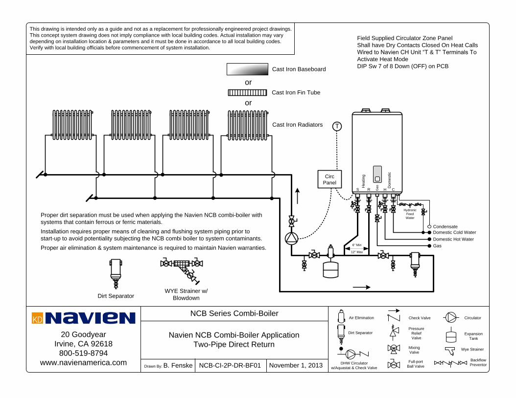
PreventorNCB-CI-2P-DR-BF01
Air Elimination
Dirt Separator
NCB Series Combi-Boiler
Navien NCB Combi-Boiler Application
Two-Pipe Direct Return
H
Gas
Hydronic
Feed
Water
Domestic Hot Water
Domestic Cold Water
Condensate
Ga
s Do
me
stic
He
atin
g
S R C
6" Min
12" Max
Field Supplied Circulator Zone Panel
Shall have Dry Contacts Closed On Heat Calls
Wired to Navien CH Unit “T & T” Terminals To
Activate Heat Mode
DIP Sw 7 of 8 Down (OFF) on PCB
T
Circ
Panel
or
Cast Iron Baseboard
Cast Iron Fin Tube
Cast Iron Radiators
or
Proper dirt separation must be used when applying the Navien NCB combi-boiler with
systems that contain ferrous or ferric materials.
Installation requires proper means of cleaning and flushing system piping prior to
start-up to avoid potentiality subjecting the NCB combi boiler to system contaminants.
Proper air elimination & system maintenance is required to maintain Navien warranties.
Dirt SeparatorWYE Strainer w/
Blowdown

20 Goodyear
Irvine, CA 92618
800-519-8794
www.navienamerica.com
Check Valve Circulator
Drawn By: B. Fenske November 1, 2013
Pressure
Relief
ValveExpansion
Tank
Wye Strainer
Full-port
Ball Valve
Mixing
Valve
DHW Circulator
w/Aquastat & Check Valve
This drawing is intended only as a guide and not as a replacement for professionally engineered project drawings.
This concept system drawing does not imply compliance with local building codes. Actual installation may vary
depending on installation location & parameters and it must be done in accordance to all local building codes.
Verify with local building officials before commencement of system installation.
Backflow
PreventorNCB-CI-2P-RR-BF01
Air Elimination
Dirt Separator
NCB Series Combi-Boiler
Navien NCB Combi-Boiler Application
Two-Pipe Reverse Return
Field Supplied Circulator Zone Panel
Shall have Dry Contacts Closed On Heat Calls
Wired to Navien CH Unit “T & T” Terminals To
Activate Heat Mode
DIP Sw 7 of 8 Down (OFF) on PCB
Proper dirt separation must be used when applying the Navien NCB combi-boiler with
systems that contain ferrous or ferric materials.
Installation requires proper means of cleaning and flushing system piping prior to
start-up to avoid potentiality subjecting the NCB combi boiler to system contaminants.
Proper air elimination & system maintenance is required to maintain Navien warranties.
Dirt SeparatorWYE Strainer w/
Blowdown
H
Gas
Hydronic
Feed
Water
Domestic Hot Water
Domestic Cold Water
Condensate
Ga
s Do
me
stic
He
atin
g
S R C
6" Min
12" Max
T
Circ
Panel
or
Cast Iron Baseboard
Cast Iron Fin Tube
Cast Iron Radiators
or

20 Goodyear
Irvine, CA 92618
800-519-8794
www.navienamerica.com
Check Valve Circulator
Drawn By: B. Fenske November 1, 2013
Pressure
Relief
ValveExpansion
Tank
Wye Strainer
Full-port
Ball Valve
Monoflo
Tee
DHW Circulator
w/Aquastat & Check Valve
This drawing is intended only as a guide and not as a replacement for professionally engineered project drawings.
This concept system drawing does not imply compliance with local building codes. Actual installation may vary
depending on installation location & parameters and it must be done in accordance to all local building codes.
Verify with local building officials before commencement of system installation.
Backflow
PreventorNCB-CI-MONO-BF01
Air Elimination
Dirt Separator
NCB Series Combi-Boiler
Navien NCB Combi-Boiler Application
One-Pipe (Monoflo) Distribution System
H
Gas
Hydronic
Feed
Water
Domestic Hot Water
Domestic Cold Water
Condensate
Ga
s Do
me
stic
He
atin
g
S R C
6" Min
12" Max
Field Supplied Circulator Zone Panel
Shall have Dry Contacts Closed On Heat Calls
Wired to Navien CH Unit “T & T” Terminals To
Activate Heat Mode
DIP Sw 7 of 8 Down (OFF) on PCB
T
Circ
Panel
or
Cast Iron Baseboard
Cast Iron Fin Tube
Cast Iron Radiators
or
Proper dirt separation must be used when applying the Navien NCB combi-boiler with
systems that contain ferrous or ferric materials.
Installation requires proper means of cleaning and flushing system piping prior to
start-up to avoid potentiality subjecting the NCB combi boiler to system contaminants.
Proper air elimination & system maintenance is required to maintain Navien warranties.
Dirt SeparatorWYE Strainer w/
Blowdown

20 Goodyear
Irvine, CA 92618
800-519-8794
www.navienamerica.com
Check Valve Circulator
Drawn By: B. Fenske November 1, 2013
Pressure
Relief
ValveExpansion
Tank
Full-port
Ball Valve
Mixing
Valve
DHW Circulator
w/Aquastat & Check Valve
This drawing is intended only as a guide and not as a replacement for professionally engineered project drawings.
This concept system drawing does not imply compliance with local building codes. Actual installation may vary
depending on installation location & parameters and it must be done in accordance to all local building codes.
Verify with local building officials before commencement of system installation.
Backflow
PreventorNCB-DHWR-BF01
Air Elimination
Solenoid
Valve
NCB Series Combi-Boiler
Navien NCB Combi-Boiler Application
DHW Recirculation Shown
S
H
Gas
Hydronic
Feed
Water
Domestic Hot Water
Domestic Cold Water
Condensate
Ga
s Do
me
stic
He
atin
g
S R C
6" Min
12" Max
*
System Return
DHW Circulator Requirements:
1. S.S. or Bronze Body & Impeller
* DHW Side 2.5 PSI Pressure drop @ 2 GPM
2. > 0.5 GPM to Activate Burner
3. Maximum 2 GPM
4. Programmable Timer
5. Selectable Aquastat
* Set minimum 5°F below NCB DHW Setpoint
Purge
Valve

20 Goodyear
Irvine, CA 92618
800-519-8794
www.navienamerica.com
T
Check Valve Circulator
Drawn By: B. Fenske November 1, 2013
Pressure
Relief
ValveExpansion
Tank
Aquastat
Full-port
Ball Valve
Mixing
Valve
DHW Circulator
w/Aquastat & Check Valve
This drawing is intended only as a guide and not as a replacement for professionally engineered project drawings.
This concept system drawing does not imply compliance with local building codes. Actual installation may vary
depending on installation location & parameters and it must be done in accordance to all local building codes.
Verify with local building officials before commencement of system installation.
Backflow
PreventorNCB-NPE-BF01
Air Elimination
Solenoid
Valve
NCB Series Combi-Boiler & NPE (A/S) Series Tankless
Navien NCB Combi-Boiler Application
With NPE-A or S Tankless Water Heater
S
H
Gas
Hydronic
Feed
Water
Domestic Cold Water
Condensate
Ga
s Do
me
stic
He
atin
g
S R C
6" Min
12" Max
CH
Domestic Hot Water
Communication
Cable
Ga
s
Opt. DHW Recirculation – “A” Model
S

20 Goodyear
Irvine, CA 92618
800-519-8794
www.navienamerica.com
T
Check Valve Circulator
Drawn By: B. Fenske November 1, 2013
Pressure
Relief
ValveExpansion
Tank
Aquastat
Full-port
Ball Valve
Mixing
Valve
DHW Circulator
w/Aquastat & Check Valve
This drawing is intended only as a guide and not as a replacement for professionally engineered project drawings.
This concept system drawing does not imply compliance with local building codes. Actual installation may vary
depending on installation location & parameters and it must be done in accordance to all local building codes.
Verify with local building officials before commencement of system installation.
Backflow
PreventorNCB-2NPE-BF01
Air Elimination
Solenoid
Valve
NCB Series Combi-Boiler & NPE (A/S) Series Tankless
Navien NCB Combi-Boiler Application
With Two NPE-A or S Tankless Water Heater
S
H
Gas
Hydronic
Feed
Water
Domestic Cold Water
Condensate
Ga
s Do
me
stic
He
atin
g
S R C
6" Min
12" Max
CH
Communication
Cable
Ga
s
S
CH
Domestic Hot Water
Ga
s
Opt. DHW Recirculation
NPE– “A” Models
Communication
Cable