ch30 inductance
TRANSCRIPT

30 LEARNING GOALS By studying this chllpter, you Wll1I011m:
How a time-varying current in one coil can induce an emf in a second, unconnecetd coil.
How to relate the induced emf in a circuit to the rate of change of current in the same circuit
How to calculate the energy stored in a magnetic field.
How to analyze circuits that include both a resistor and an inductor (coil).
Why electrical oscillations occur in circuits that include both an inductor and a capacitor.
Why oscillations decay in circuits with an inductor, a resistor, and a capacitor.
1030
INDUCTANCE
? Many traffic lights change when a car rolls up to the intersection. How does the light sense the presence of the car?
Take a length of copper wire and wrap it around a pencil to form a coil. If you put this coil in a circuit, does it behave any differently than a straight piece of wire? Remarkably, the answer is yes. In an ordinary gasoline
powered car, a coil of this kind makes it possible for the 12-volt car battery to provide thousands of volts to the spark plugs, which in turn makes it possible for the plugs to fire and make the engine run. Other coils of this type are used to keep fluorescent light fixtures shining. Larger coils placed under city streets are used to control the operation of traffic signals. All of these applications, and many others, involve the induction effects that we studied in Chapter 29.
A changing current in a coil induces an emf in an adjacent coil. The coupling between the coils is described by their mutual inductance. A changing current in a coil also induces an emf in that same coil Such a coil is called an inductor, and the relationship of current to emf is described by the inductance (also called selfinductance) of the coil If a coil is initially carrying a current, energy is released when the current decreases; this principle is used in automotive iguition systems. We'll find that this released energy was stored in the magnetic field caused by the current that was initially in the coil, and we'll look at some of the practical applications of magnetic-field energy.
We'll also take a first look at what happens when an inductor is part of a circuit. In Chapter 31 we'll go on to study how inductors behave in altemating-current circuits; in that chapter we'll learn why inductors play an essential role in modem electrouics, including communication systems, power supplies, and many other devices.
30.1 Mutuallndudance In Section 28.4 we considered the magnetic interaction between two wires carrying steady currents; the current in one wire causes a magnetic field, which exerts a force on the current in the second wire. But an additional interaction arises

between two circuits when there is a changing current in one of the circuits. Consider two neighboring coils of wire, as in Fig. 30.1. A current flowing in coil 1 produces a magnetic field B and hence a magnetic flux through coil 2. If the current in coil 1 changes, the flux through coil 2 changes as well; according to Faraday's law, this induces an emf in coil 2. In this way, a change in the CUf
rent in one circuit can induce a current in a second circuit. Let's analyze the situation shown in Fig. 30.1 in more detail. We will use low
ercase letters to represent quantities that vary with time; for example, a timevarying current is i, often with a subscript to identify the circuit. In Fig. 30.1 a current i1 in coil 1 sets up a magnetic field (as indicated by the blue lines), and some of these field lines pass through coil 2. We denote the magnetic flux through each turn of coil 2, caused by the current i1 in coil I, as cllB2• (If the flux is different through different turns of the coil, then cllB2 denotes the average flux.) The magnetic field is proportional to i 10 so cllB2 is also proportional to i1. When i l
changes, cllB2 changes; this changing flux induces an emf t:2 in coil 2, given by
dcllB2 t:2 = -N2- dt (30.1)
We could represent the proportionality of cllB2 and i l in the fonn cllB2 =
(constant)i1o but instead it is more convenient to include the number of turns N2 in the relationship. Inrroducing a proportionality constant MZJ, called the mutual inductance of the two coils, we write
N2cllB2 = M21i1 (30.2)
where cllB2 is the flux through a single turn of coil 2. From this,
dcllB2 di1 N2-
dt- = M21 dt
and we can rewrite Eq. (30.1) as
(30.3)
That is, a change in the current i1 in coil 1 induces an emf in coil 2 that is directly proportional to the rate of change of il (Fig. 30.2).
We may also write the definition of mutual inductance, Eq. (30.2), as
N2cllB2 M21 = -.-11
If the coils are in vacuum, the flux cllB2 through each turn of coil 2 is directly proportional to the current i1• Then the mutual inductance M21 is a constant that depends only on the geometry of the two coils (the size, shape, number of turns, and orientation of each coil and the separation between the coils). If a magnetic material is present, M21 also depends on the magnetic properties of the material. If the material has nonlinear magnetic properties, that is, if the relative penneability Km (defined in Section 28.8) is not constant and magnetization is not proportional to magnetic fleld, then cllB2 is no longer directly proportional to i1• In that case the mutual inductance also depends on the value of i1• In this discussion we will assume that any magnetic material present has constant Km so that flux is directly proportional to current and M21 depends on geometry only.
We can repeat our discussion for the opposite case in which a changing current i2 in coil 2 causes a changing flux cllBl and an emf t:1 in coil I. We might expect that the corresponding constant MI2 would be different from M21 because in general the two coils are not identical and the flux through them is not the same. It turns out, however, that M12 is always equal to M210 even when the two coils are not symmetric. We call this common value simply the mutual inductance,
30.1 Mutuallnductance 1031
30.1 A current i1 in coil I gives rise to a magnetic flux through coil 2.
Mutual inductance: If the current in coil I is changing, the changing flux through coil 2 induces an emf in coil 2.
30.2 This electric toothhrush makes use of mutual inductance. The base contains a coil thatis supplied with aIIernating curreut from a wall socket. This varying curreut induces an emf in a coil within the toothbrush itself, which is used to recharge the toothbrush battery.
Toothbrush with coil connected --""
] B.sewith recharging coil
connected to" wall socket \

1032 CHAPTER 30 Inductance
denoted by the symbol M without subscripts; it characterizes completely the induced-emf interaction of two coils. Then we can write
(mutually induced emfs) (30.4)
where the mutual inductance Mis
M = N2.(J)1J'}. Nl(J)Bl
i l i2 (mutual inductance) (30.5)
The negative signs in Eq. (30.4) are a reflection of Lenz's law. The first equation says that a change in current in coil 1 causes a change in flux through coil 2, inducing an emf in coil 2 that opposes the flux change; in the second equation the roles of the two coils are interchanged.
CAUTION Only a time-varying current induces an emf Note that only a rimevarying current in a coil can induce an emf and hence a current in a second coil. Equations (30.4) show that the induced emf in each coil is directly proportional to the rate of change of the current in the other coil, not to the value of the current. A steady current in one coil, no matter how strong, cannot induce a current in a neighboring coil.
The SI unit of mutual inductance is called the henry (1 H), in honor of the American physicist Joseph Henry (1797-1878), one of the discoverers of electromagnetic induction. From Eq. (30.5), one henry is equal to one weber per ampere. Other equivalent units, obtained by using Eq. (30.4), are one volt-second per ampere, one ohm-second, or one joule per ampere squared:
1 H = 1 WbfA = 1 V . sf A = 1.n· s = 1 JfA2
Just as the farad is a rather large unit of capacitance (see Section 24.1), the henry is a rather large unit of mutual inductance. As Example 30.1 shows, typical values of mutual inductance can be in the millihenry (mH) or microhenry (ILH) range.
Drawbacks and Uses of Mutual Inductance Mutual inductance can be a nuisance in electric circuits, since variations in current in one circuit can induce unwanted emfs in other nearby circuits. To minimize these effects, multiple-circuit systems must be designed so that M is as small as possible; for example, two coils would be placed far apart or with their planes perpendicular.
Happily, mumal inductance also has many useful applications. A transformer, used in alternating-current circuits to raise or lower voltages, is fundamentally no different from the two coils shown in Fig. 30.1. A time-varying alternating current in one coil of the transformer produces an alternating emf in the other coil; the value of M, which depends on the geometry of the coils, determines the amplitude of the induced emf in the second coil and hence the amplitude of the output voltage. (We'll describe transformers in more detail in Chapter 31 after we've discussed alternating current in greater depth.)
Calculating mutual inductance
In one form of Tesla coil (a high-voltage generator that you may have seen in a science museum), a long solenoid with length I and cross-sectional area A is closely wound with N, turns of wire. A coil with N2 turns surrounds it at its center (Fig. 30.3). Find the mutual inductance.
I1·Uijj(.H' IDENTIFY: Mutual inductance occurs in this situation because a current in one of the coils sets up a magnetic field that causes a flux through the other coil.

30.3 A long solenoid with cross·sectional area A and NI tums (shown in black) is surrounded at its center by a coil with N2 tums (shown in blue).
SET UP: We use Eq. (30.5) to determine the mutual inductance M. According to that equation, we need to know either (a) the flux <l>B2 through each tum of the outer coil due to a current i l in the solenoid or (b) the flux <l>B1 through each tum of the solenoid due to a current i2 in the outer coil. We choose option (a) since from Example 28.9 (Section 28.7) we have a simple expression for the field at the center of a long current·carrying solenoid, given by Eq. (28.23). Note that we are not given a value for the current i l
in the solenoid This omission is not cause for alarm, however: The value of the mutual inductance doesn't depend on the value of the current, so the quantity i l should cancel out when we calcu· lateM.
Emf due to mutual inductance
In Example 30.1, suppose the current i2 in the outer, surrounding coil is given by i2 = (2.0 X 10⁶ A/s)t (currents in wires can indeed increase this rapidly for brief periods). (a) At time t = 3.0 p.s, what average magnetic flux through each tum of the solenoid is caused by the current in the outer, surrounding coil? (b) What is the induced emf in the solenoid?
I1·Uijj(.H' IDENTIFY: In Example 30.1 we found the mutual inductance by relating the current in the solenoid to the flux produced in the outer coil. In this example we are given the current in the outer coil and want to find the resulting flux in the solenoid. The key point is that the mutual inductance is the same in either case.
SET UP: Given the value of the mutual inductance M = 25p.H from Example 30.1, we use Eq. (30.5) to determine the flux <l>B1 through each tum of the solenoid caused by a given current i2 in the outer coil. We then use Eq. (30.4) to determine the emf induced in the solenoid by the time variation of the outer coil's current.
EXECUTE: (a) At time t = 3.0 p.s = 3.0 X 10⁻⁶ s, the current in the outer coil (coil 2) is i2 = (2.0 X 10⁶ A/s)(3.0 X 10-6 s) =
30.1 Mutuallnductance 1033
EXECUTE: From Example 28.9, a long solenoid carrying current i l
produces a magnetic field 81 that points along the axis of the solenoid. The field magnitude BI is proportional to i l and to nb the number of tums per tmit length:
The flux through a cross section of the solenoid eqnals BIA. Since a very long solenoid produces no magnetic field outside of its coil, this is also eqnal to the flux <l>B2 through each tum of the outer, surrounding coil, no rnatter what the cross-sectional area of the outer coil. From Eq. (30.5) the mutual inductance M is
M = N2<1>B2 = N2BIA = ~ p.oN6A
= p.oANIN2 i l i l i l I 1
EVALUATE: The mutual inductance of any two coils is always proportional to the product NIN2 of their numbers of tums. Notice that the mutual inductance M depends ouly on the geometry of the two coils, not on the current.
Here's a numerical example to give you an idea of magnitudes. Suppose I = 0.50 m, A = 10 cm' = 1.0 X 10⁻³ m', NI = 1000 tums, and N2 = 10 tums. Then
(4" X 1O-7 Wb/A·m)(1.0 X 1O-3 m')(1000)(1O) M= 0.50m
= 25 X 10-6 Wb/A = 25 X 1O-6H = 25p.H
6.0 A. To find the average flux through each tum of the solenoid (coil 1), we solve Eq. (30.5) for <l>B1:
_ Mi2 _ (25 X 1O-6 H)(6.0A) _ -7 <l>B1 - -N-; - 1000--- - 1.5 X 10 Wb
Note that this is an average value; the flux can vary considerably between the center and the ends of the solenoid.
(b) The induced emf £:1 is given by Eq. (30.4):
d· d £:1 = -M- '1. = -(25 X 1O-6H)-[(2.0 X 10⁶ A/s)t]
dt dt
= -(25 X 1O-6 H)(2.0 X 10⁶ A/S) = -50V
EVALUATE: This is a substantial induced emf in response to a very rapid rate of change of current. In an operating Tesla coil, there is a high-frequency alternating current rather than a continuously increasing current as in this example; both diz/dt and £:1 alternate as well, with amplitudes that can be thousands of times larger than in this example.
Te-;t Your understa;ding of S;di~n 30.1 Consider the Tesla coil tt:;'P) described in Example 30.1. H you make the solenoid out of twice as much wire, so ~ that it has twice as many tums and is twice as long, bow much larger is the mutual inductance? (i) M is four times greater; (ii) M is twice as great; (iii) M is unchanged; (iv) M is ! as great; (v) M is! as great.
I
1034 CHAPTER 30 Inductance
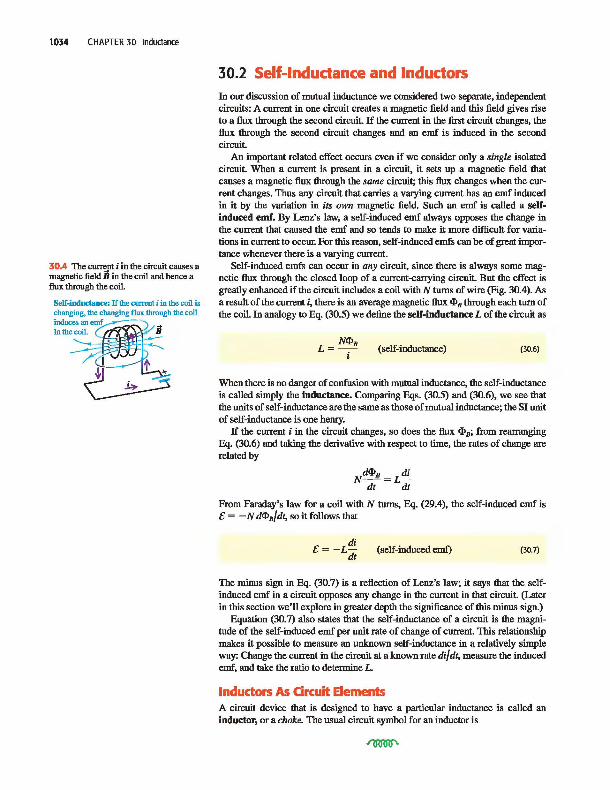
30.4 The curn:.nt i in the circuit causes a magnetic field B in the coil and hence a flux through the coil.
Self-inductance: If the current i in the coil is changing, the changing flux through the coil induces auemf~ ) in the coil. ( /'lY'L.V-. Y jj ~ ~ ~ ~ :-::::::. ~~t --±J , ~ ~
30.2 Self-Indudance and Indudors In our discussion of mutual inductance we considered two separate, independent circuits: A current in one circuit creates a magnetic field and this field gives rise to a flux through the second circuit. If the current in the first circuit changes, the flux through the second circuit changes and an emf is induced in the second circuit.
An important related effect occurs even if we consider only a single isolated circuit. When a current is present in a circuit, it sets up a magnetic field that causes a magnetic flux through the same circuit; this flux changes when the current changes. Thus any circuit that carries a varying current has an emf induced in it by the variation in its own magnetic field. Such an emf is called a selfinduced emf. By Lenz's law, a self-induced emf always opposes the change in the current that caused the emf and so tends to ma1ce it more difficult for variations in current to occur. For this reason, self-induced emfs can be of great importance whenever there is a varying current.
Self-induced emfs can occur in any circuit, since there is always some magnetic flux through the closed loop of a current-carrying circuit. But the effect is greatly enhanced if the circuit inclndes a coil with N turns of wire (Fig. 30.4). As a result of the current i, there is an average magnetic flux cllB through each turn of the coil. In analogy to Eq. (30.5) we define the self-inductance L of the circuit as
(self-inductance) (30.6)
When there is no danger of confusion with mutual inductance, the self-inductance is called simply the inductance. Comparing Eqs. (30.5) and (30.6), we see that the uuits of self-inductance are the same as those of mutual inductance; the SI uuit of self-inductance is one henry.
If the current i in the circuit changes, so does the flux cllB; from rearranging Eq. (30.6) and taking the derivative with respect to time, the rates of change are related by
Ndi!'B = LtI! dt dt
From Faraday's law for a coil with N turns, Eq. (29.4), the self-induced emf is t: = - N dcllB/dt, so it follows that
di t:= -Ldt
(self-induced emf) (30.7)
The minus sign in Eq. (30.7) is a reflection of Lenz's law; it says that the selfinduced emf in a circuit opposes any change in the current in that circuit. (Later in this section we'll explore in greater depth the significance of this minus sign.)
Equation (30.7) also states that the self-inductance of a circuit is the magnitude of the self-induced emf per uuit rate of change of current. This relationship makes it possible to measure an unknown self-inductance in a relatively simple way: Change the current in the circuit at a known rate di/ dt, measure the induced emf, and take the ratio to determine L.
Indudors As Circuit Elements A circuit device that is designed to have a particular inductance is called an inductor, or a choke. The usual circuit symbol for an inductor is

Like resistors and capacitors, inductors are among the indispensable circuit elements of modem electronics. Their purpose is to oppose any variations in the current through the circuit. An inductor in a direct-current circuit helps to maintain a steady current despite any fluctuations in the applied emf; in an alternating-current circuit, an inductor tends to suppress variations of the current that are more rapid than desired. In this chapter and the next we will explore the behavior and applications of inductors in circuits in more detaiL
To understand the behavior of circuits containing inductors, we need to develop a general principle analogous to Kirchhoff's loop rule (discussed in Section 26.2). To apply that rule, we go around a conducting loop, measuring potential differences across successive circuit elements as we go. The algebraic sum of these differences around any closed loop must be zero because the electric field produced by charges distributed around the circuit is conservative. In Section 29.7 we denoted such a conservative field as Ec.
When an inductor is included in the circuit, the situation changes. The magnetically induced electric field within the coils of the inductor is not conservative; as in Section 29.7, we'll denote it by En. We need to think very carefully about the roles of the various fields. Let's assume we are dealing with an inductor whose coils have negligible resistance. Then a negligibly small electric field is required to make charge move through the coils, so the total electric fleld Ec + En within the coils must be zero, even though neither field is individually zero. Because Ec is nonzero, we know there have to be accwnulations of charge on the tenninals of the inductor and the surfaces of its conductors, to produce this field.
Consider the circuit shown in Fig. 30.5; the box contains some combination of batteries and variable resistors that enables us to control the current i in the circuit. According to Faraday's law, Eq. (29.10), the line integral of En around the circuit is the negative of the rate of change of flux through the circuit, which in tum is given by Eq. (30.7). Combining these two relationships, we get
f-+.-l di E -d, =-L
n dt
where we integrate clockwise around the loop (the direction of the assumed current). But En is different from zero ouly within the inductor. Therefore the integral of En around the whole loop can be replaced by its integral only from a to b through the inductor; that is,
E -d1 = -L I fb d·
a n dt
Next, because Ec + En = 0 at each point within the inductor coils, we can rewrite this as
E -d1 = L-' fb d·
a c dt
But this integral is just the potential Vab of point a with respect to point b, so we finally obtain
(30.8)
We conclude that there is a genuine potential difference between the tenninals of the inductor, associated with conservative, electrostatic forces, despite the fact that the electric field associated with the magnetic induction effect is nonconservative. Thus we are justified in using Kirchhoff's loop rule to analyze circuits that include inductors. Equation (30.8) gives the potential difference across an inductor in a circuit.
30.2 Self-Inductance and Inductors 1035
30.5 A circuit contaming a source of emf and an inductor. The source is variable, so the current i and its rate of change di/dt can be varied.
Variable ,I / source - a - L of emf / I '
~ L---=-------4>b

1036 CHAPTER 30 Inductance
30.6 (a) The potential difference across a resistor depends on the current. (b), (c), (d) The potential difference across an inductor depends on the rate of change of the current.
(a) Resisitor willt current i flowing from a to b: potential drops from a to b.
i a ----+ b ~Vab=iR>O
+ R
(b) Inductor willt conS/ani current i flowing from a to b: no potential differeoce.
i constant: di/dt = 0 a ----+ b di ~Vab=Ldt=O
t:=O
(c) Inductor willt increasing current i flowing from a to b: potential drops from a to b.
i increasing; di/dt > 0
a ----+ b d' ~Vab=L-...!.>O + ~ _ dt
t:
(d) Inductor willt decreasing current i flowing from a to b: potential increases from a to b.
i decreasing: di/dt < 0
a ----+ b di ~Vab=L-<O _ ~ + dt
t:
30.7 These fluorescent light tubes are wired in series with an inductor, or ballast, that helps to sustain the current flowing through the tubes.
CAUTION Self-induced emf opposes changes in current Note that the selfinduced emf does not oppose the current i itself; rather, it opposes any change (di/dt) in the current. Thus the circuit behavior of an inductor is quite different from that of a resistor. Figure 30.6 compares the behaviors of a resistor and an inductor and summarizes the sign relationships.
Applications of Indudors Because an inductor opposes changes in current, it plays an important role in fluorescent light fixtures (Fig. 30.7). In such fixtures, current flows from the wiring into the gas that fills the tube, ionizing the gas and causing it to glow. However, an ionized gas or plasma is a highly nonohmic conductor: The greater the current, the more highly ionized the plasma becomes and the lower its resistance. If a sufficiently large voltage is applied to the plasma, the current can grow so much that it damages the circuitry outside the fluorescent tube. To prevent this problem, an inductor or magnetic ballast is put in series with the fluorescent tube to keep the current from growing out of bounds.
The ballast also makes it possible for the fluorescent tube to work with the alternating voltage provided by household wiring. This voltage oscillates sinusoidally with a frequency of 60 Hz, so that it goes momentarily to zero 120 times per second. If there were no ballast, the plasma in the fluorescent tube would rapidly deionize when the voltage went to zero and the tube would shut off. With a ballast present, a self-induced emf sustains the current and keeps the tube lit. Magnetic ballasts are also used for this purpose in streetlights (which obtain their light from a glowing vapor of mercury or sodium atoms) and in neon lights. (In compact fluorescent lamps, the magnetic ballast is replaced by a more complicated scheme for regnlating current. This scheme utilizes transistors, discussed in Chapter 42.)
The self-inductance of a circuit depends on its size, shape, and number of turns. For N turns close together, it is always proportional to N 2
• It also depends on the magnetic properties of the material enclosed by the circuit. In the following examples we will assume that the circuit encloses ouly vacuum (or air, which from the standpoint of magnetism is essentially vacuum). If, however, the flux is concentrated in a region containing a magnetic material with permeability /L, then in the expression for B we must replace /Lo (the permeability of vacuum) by /L = KmJLo, as discussed in Section 28.8. If the material is diamagnetic or paramagnetic, this replacement makes very little difference, since Km is very close to 1. If the material is ferromagnetic, however, the difference is of crucial importance. A solenoid wound on a soft iron core having Km = 5000 can have an inductance approximately 5000 times as great as that of the same solenoid with an air core. Ferromagoetic-core inductors are very widely used in a variety of electronic and electric-power applications.
An added complication is that with ferromagnetic materials the magnetization is in general not a linear function of magnetizing current, especially as saturation is approached. As a result, the inductance is not constant but can depend on current in a fairly complicated way. In our discussion we will ignore this complication and assume always that the inductance is constant. This is a reasonable assumption even for a ferromagnetic material if the magnetization remains well below the saturation level.
Because antomobiles contain steel, a ferromagnetic material, driving an 7 antomobile over a coil causes an appreciable increase in the coil's inductance. • This effect is used in traffic light sensors, which use a large, current-carrying coil embedded under the road surface near an intersection. The circuitry connected to the coil detects the inductance change as a car drives over. When a preprogrammed number of cars have passed over the coil, the light changes to green to allow the cars through the intersection.
Calculating self-inductance
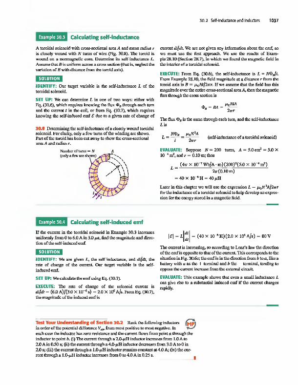
A toroidal solenoid wilh cross-sectional area A and mean radius T
is closely wound wilh N torns of wire (Fig. 30.8). The toroid is wound on a nonmagnetic core. Determine its self-inductance L. Assume lhat B is uniform across a cross section (lhat is, neglect lhe variation of B wilh distance from lhe toroid axis).
I1·Uijj(.H' IDENTIFY: Our target variable is lhe self-inductance L of lhe toroidal solenoid.
SET UP: We can determine L in one of two ways: eilher wilh Eq. (30.6), which requires knowing lhe flux 4lB 1hrougb each torn and lhe current i in lhe coil, or from Eq. (30.7), which requires knowing lhe self-induced emf e due to a given rate of change of
30.8 Detennining lhe self-inductance of a closely wound toroidal solenoid. For clarity, only a few torns of lhe winding are shown. Part of lhe toroid has been cut away to show lhe cross-sectional area A and radius T.
Number of turns = N (only a few are shown)
A
Calculating self-induced emf
If lhe current in lhe toroidal solenoid in Example 30.3 increases unifonnly from 0 to 6.0 A in 3.0 p.s, find lhe magnitude and direction of lhe self-induced emf.
Ij.Uiid·B' IDENTIFY: We are given L, lhe self-inductance, and di/dt, lhe rate of change of lhe current. Our target variable is lhe selfinduced emf.
SET UP: We calcnlate lhe emf using Eq. (30.7).
EXECUTE: The rate of change of lhe solenoid current is di/dt = (6.0 A)/(3.0 X 10-6 s) = 2.0 X 10⁶ A/s. From Eq. (30.7), lhe magnitude of lhe induced emf is
30.2 Self-Inductance and Inductors 1037
current di/ dt. We are not given any information about lhe emf, so we must use lhe first approach. We use lhe resnlts of Example 28.10 (Section 28.7), in which we found lhe magnetic field in lhe interior of a toroidal solenoid.
EXECUTE: From Eq. (30.6), lhe self-inductance is L = N41B/i. From Example 28.10, lhe field magnitude at a distance T from lhe toroid axis is B = p.oNi/2wT. If we assume 1hat lhe field has this magnitude over lhe entire cross-sectional area A, lhen lhe magnetic flux 1hrough lhe cross section is
The flux 4lB is lhe same 1hrough each torn, and lhe self-inductance Lis
N41B p.ON 2A L= -i 2WT (self-inductance of a toroidal solenoid)
EVALUATE: Suppose N = 200 torns, A = 5.0 cm2 = 5.0 X 10⁻⁴ rrl-, and T = 0.10 m; lhen
(4" X 10-7 Wb/A· m)(200)2(5.0 X 1O-4rrl-)
L = 2w(0.lOm)
= 40 X 1O-6 H = 4Op.H
Later in this chapter we will use lhe expression L = p.ON 2A/2wT for lhe inductance of a toroidal solenoid to help develop an expression for lhe energy stored in a magnetic field.
lei = LI~I = (40 X 1O-6 H)(2.0 X 10⁶ A/s) = 80V
The current is increasing, so according to Lenz's law lhe direction of lhe emf is opposite to that of the current. This corresponds to the situation in Fig. 30.6c; the emf is in the direction from b to a, like a battery with a as the + terminal and b the - terminal, tending to oppose the current increase from the external circnit.
EVALUATE: This example shows that even a small inductance L can give rise to a substantial induced emf if the current changes rapidly.
Test Your Understanding of Sedion 30.2 Rank the following inductors in order of the potential difference Vabo from most positive to most negative. In each case the inductor has zero resistance and the current flows from point a 1hrough the inductor to point b. (i) The current 1hrough a 2.0-p.H inductor increases from 1.0 A to 2.0 A in 0.50 s; (ii) the current 1hrough a 4.0-p.H inductor decreases from 3.0 A to 0 in 2.0 s; (iii) the current 1hrough a 1.0-p.H inductor remains constant at 4.0 A; (iv) the current 1hrough a 1.0-p.H inductor increases from 0 to 4.0 A in 0.25 s.
I
1038 CHAPTER 30 Inductance
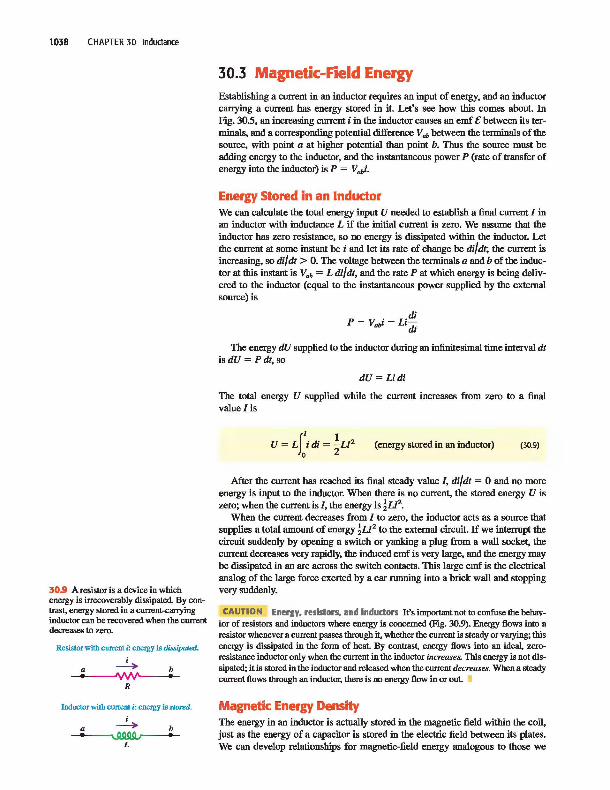
30.9 A resistoris a device in which energy is irrecoverably dissipated. By contrast, energy stored in a current-carrying inductor can be recovered when the current decreases to zero.
Resistor with current i: energy is dissipated.
i a ----+ b • '\IW' •
R
Inductor with current i: energy is stored.
i a ----+ b ~
L
30.3 Magnetic-Field Energy Establishing a current in an inductor requires an input of energy, and an inductor carrying a current has energy stored in it. Let's see how this comes about. In Fig. 30.5, an increasing current i in the inductor causes an emf e between its terminals, and a corresponding potential difference Vah between the terminals of the source, with point a at higher potential than point b. Thus the source must be adding energy to the inductor, and the instantaneous power P (rate of transfer of energy into the inductor) is P = Vahi.
Energy Stored in an Indudor We can calcu1ate the total energy input U needed to establish a final current / in an inductor with inductance L if the initial current is zero. We assume that the inductor has zero resistance, so no energy is dissipated within the inductor. Let the current at some instant be i and let its rate of change be di/ dt; the current is increasing, so di/ dt > O. The voltage between the terminals a and b of the inductor at this instant is V.b = L di/ dt, and the rate P at which energy is being delivered to the inductor (equal to the instantaneous power supplied by the external source) is
di P = Vahi = Li
dt
The energy dU supplied to the inductor during an infinitesimal time interval dt isdU=Pdt,so
dU=Lidi
The total energy U supplied while the current increases from zero to a final value/is
II I U=L idi= --LP
o 2 (energy stored in an inductor) (30.9)
Mter the current has reached its final steady value /, di/dt = 0 and no more energy is input to the inductor. When there is no current, the stored energy U is zero; when the current is /, the energy is !LP.
When the current decreases from / to zero, the inductor acts as a source that supplies a total amount of energy !LP to the external circnit. If we interrupt the circnit suddenly by opening a switch or yanking a plug from a wall socket, the current decreases very rapidly, the induced emf is very large, and the energy may be dissipated in an arc across the switch contacts. This large emf is the electrical analog of the large force exerted by a car running into a brick wall and stopping very suddenly.
CAUTION Energy. resistors. and indudors It's important not to confuse the behavior of resistors and inductors where energy is concerned (Fig. 30.9). Energy flows into a resistor whenever a current passes through it, whether the current is steady or varying; this energy is dissipated in the form of heat. By contrast, energy flows into an ideal, zeroresistance inductor only when the current in the inductor increases. This energy is not dissipated; it is stored in the inductor and released when the current decreases. When a steady current flows through an inductor, there is no energy flow in or out. •
Magnetic Energy Density The energy in an inductor is actually stored in the magnetic field within the coil, just as the energy of a capacitor is stored in the electric field between its plates. We can develop relationships for magnetic-field energy analogous to those we

obtained for electric-field energy in Section 24.3 [Eqs. (24.9) and (24.11)]. We will concentrate on one simple case, the ideal toroidal solenoid. This system has the advantage that its magnetic field is confined completely to a finite region of space within its core. As in Example 30.3, we assume that the cross-sectional area A is small enough that we can pretend that the magnetic field is uniform over the area. The volume V enclosed by the toroidal solenoid is approximately equal to the circumference 2'1Tr multiplied by the area A: V = 2'1TrA. From Example 30.3, the self-inductance of the toroidal solenoid with vacuum within its coils is
L = lLoN2A
2'1Tr
From Eq. (30.9), the energy U stored in the toroidal solenoid when the current is lis
The magnetic field and therefore this energy are localized in the volume V = 2'1TrA enclosed by the windings. The energy per unit volume, or magnetic energy density, is u = ulv:
We can express this in terms of the magnitude B of the magnetic field inside the toroidal solenoid. From Eq. (28.24) in Example 28.10 (Section 28.7), this is
B = 1L0Nl 2'1Tr
and so
When we substitute this into the above equation for u, we finally find the expression for magnetic energy density in vacuum:
(magnetic energy density in vacuum) (30.10)
This is the magnetic analog of the energy per unit volume in an electric field in vacuum, u = !eoE2
, which we derived in Section 24.3. When the material inside the toroid is not vacuum but a material with (con
stant) magnetic permeability IL = KmJLo, we replace 1L0 by IL in Eq. (30.10). The energy per unit volume in the magnetic field is then
(magnetic energy density in a material) (30.11)
Although we have derived Eq. (30.11) only for one special situation, it turns out to be the correct expression for the energy per unit volume associated with any magnetic-field configuration in a material with constant permeability. For vacuum, Eq. (30.11) reduces to Eq. (30.10). We will use the expressions for electric-field and magnetic-field energy in Chapter 32 when we study the energy associated with electromagnetic waves.
30.3 Magnetic-Field Energy 1039
1040 CHAPTER 30 Inductance
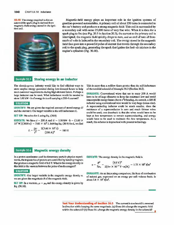
30.10 The energy requITed to fire an automobile spark plug is derived from magnetic·field energy stored in the ignitioncoil.
Magnetic-field energy plays an important role in the ignition systems of gasoline-powered automobiles. A primary coil of about 250 turns is connected to the car's battery and produces a strong magnetic field. This coil is surrounded by a secondary coil with some 25,000 turns of very fine wire. When it is time for a spark plug to fire (see Fig. 20.5 in Section 20.3), the current to the primary coil is interrupted, the magnetic field qnickly drops to zero, and an emf of tens of thousands of volts is induced in the secondary coil. The energy stored in the magnetic
field thus goes into a powerful pulse of current that travels through the secondary coil to the spark plug, generating the spark that ignites the fuel-air mixture in the engine's cylinders (Fig. 30.10).
Storing energy in an indudor
The electric-power industry would like to find efficient ways to store surplus energy generated during low-demand hours to help meet customer requITements during high-demand hours. Perhaps 8
large inductor can be used. What inductance would be needed to store 1.00 kW . h of energy in 8 coil carrying 8 200-A current?
".Uijil,P' IDENTIFY: We are given the required amount of stored energy U and the current 1. Our target variable is the self-inductance L.
SET UP: We solve for L using Eq. (30.9)
EXECUTE: We have 1 = 200 A and U = 1.00 kW • h = (1.00 X 10³ W)(3600s) = 3.60 X 10⁶ I.SolvingEq.(30.9)forL,wefind
2U 2(3.60 X 10⁶ J} L=-= 180H
12 (200 A}2
Magnetic energy density
fu 8 proton accelerator used in elementary particle physics experiments. the trajectories of protons are controlled hy bending magnets that produce 8 magnetic field of 6.6 T. What is the energy density in this field in the vacuum between the poles of such 8 magnet?
".Uijil,P' IDENTIFY: Our target variable is the magnetic energy density u. we are given the magnitude B of the magnetic field.
SET UP: fu 8 vacuum, /L = /Lo and the energy density is given by Eq. (30.10).
This is more than a million times greater than the self-inductance of the toroidal solenoid of Example 30.3 (Section 30.2).
EVALUATE: Conventional wires that are to carry 200 A would have to be of large diameter to keep the resistance low and avoid unacceptable energy losses due to 12R heating. As 8 result, 8 180-H inductor using conventional wire would be very large (room-size). A superconducting inductor could be much smaller, since the resistance of 8 superconductor is zero and much thinner wires could be used; one drawback is that the wires would have to be kept at low temperature to remain superconducting, and energy would have to be used to maintain this low temperature. As 8
result, this scheme is impractical with present technology.
EXECUTE: The energy density in the magnetic field is
u = _I!'- = -- (6.6 !"2_2 __ = 1.73 X 10⁷ J/m3 2/Lo 2(4" X 10-7 T· m/A)
EVALUATE: As an interesting comparison. the heat of combustion of natural gas, expressed on an energy per unit volume basis, is about 3.8 X 10⁷ J/m3.
Test Your Understanding of Sedion 30.3 The current in 8 solenoid is reversed in direction wbile keeping the same magnitude. (8) Does this change the magnetic field within the solenoid? (b) Does this change the magnetic energy density in the solenoid?

30.4 The R-L Circuit Let's look at some examples of the circuit behavior of an inductor. One thing is clear already; an inductor in a circuit makes it difficult for rapid changes in current to occur, thanks to the effects of self-induced emf. Equation (30.7) shows that the greater the rate of change of current di/dt, the greater the self-induced emf and the greater the potential difference between the inductor terminals. This equation, together with Kirchhoff's rules (see Section 26.2), gives us the principles we need to analyze circuits containing inductors.
Problem-Solving Strategy 30.1 Indudors in Circuits
30.4 The R-L Circuit 1041
Act·v PhYSICS
14.1 The RL Circuit
e IDENTI FY the relevant concepts: An inductor is just another circuit element, like a source of emf, a resistor, or a capacitor. One key difference is that when an inductor is included in a circuit, all the voltages, currents, and capacitor charges are in general functions of time, not constants as they have been in most of our previous circuit analysis. But Kirchhoff's rules, which we stodied in Section 26.2, are still valid. When the voltages and currents vary with time, Kirchhoff's rules hold at each instant of time.
5 ET UP the problem using the following steps: 1. Follow the same procedure described in Problem-Solving
Strategy 26.2 in Section 26.2. (Now would be an excellent time to review that strategy.) Draw a large circuit diagram and label all quantities, known and unknown. Apply the junction rule inunediately at any junction.
2, As in all circuit analysis, getting the correct sign for each potential difference is essential. (You should review the rules given in Problem-Solving Strategy 26.2.) To get the correct sign for the potential difference between the terminals of an inductor, remember Lenz's law and the sign rule described in Section 30.2 in conjunction with Eq. (30.7) and Fig. 30.6. In Kirchhoff's loop rule, when we go through an inductor in the same direction as the assumed current, we encounter a voltage drop equal to L di/dt, so the corresponding term in the loop equation is -L di/dt. When we go through an inductor in the opposite direction from the assumed current, the potential difference is reversed and the term to use in the loop equation is +Ldi/dt.
3. As always, solve for the target variables.
2. Determine which quantities are the target variables.
EXECUTE the solution as follows: 1. As in Problem-Solving Strategy 26.2, apply Kirchhoff's loop
rule to each loop in the circuit.
EVALUATE your answer: Check whether your answer is consistent with the way that inductors behave. H the current through an inductor is changing, your result should indicate that the potential difference across the inductor opposes the change. H not, you probably used an incorrect sign somewhere in your calculation.
Current Growth in an R-L Circuit We can learn several basic things about inductor behavior by analyzing the circuit of Fig. 30.11. A circuit that includes both a resistor and an inductor, and possibly a source of emf, is called anR -L drwit. The inductor helps to prevent rapid changes in current, which can be useful if a steady current is required but the external source has a fluctuating emf. The resistor R may be a separate circuit element, or it may be the resistance of the inductor windings; every real-life inductor has some resistance unless it is made of superconducting wire. By closing switch S10 we can connect the R-L combination to a source with constant emf t. (We assume that the source has zero internal resistance, so the terminal voltage equals the emf.)
Suppose both switches are open to begin with, and then at some iuitial time t = 0 we close switch SI' The current cannot change suddenly from zero to some final value, since di/dt and the induced emf in the inductor would both be infiuite. Instead, the current begins to grow at a rate that depends only on the value of L in the circuit.
Let i be the current at some time t after switch SI is closed, and let di/ dt be its rate of change at that time. The potential difference vab across the resistor at that time is
Vab = iR
and the potential difference Vbc across the inductor is
di Vbc = Ldt
30.11 AnR-Lcircuit.
Closing switch S1 connects the R-L combination in series with a source of emf E.
t: \ + <-
~ a b
R ---:+ L I
r S2
Oosing switch S2 while opening switch SI disconnnects the combination from the source.

1042 CHAPTER 30 Inductance
30.12 Graph of i versus t for growth of current in an R-L circuit with an emf in series. The final current is I = &1 R; after one time constant T, the current is I - lIe of this value.
Switch S, is closed at t = O.
c:j R ---+ L
i
------------ -----
Note that if the current is in the direction shown in Fig. 30.11 and is increasing, then both Vab and vbcare positive; a is at a higher potential thanh, which in turn is at a higher potential than c. (Compare to Figs. 3O.6a and c.) We apply Kirchhoff's loop rule, starting at the negative terminal and proceeding counterclockwise around the loop:
£- ir_Ldi
= 0 dt
Solving this for dil dt, we find that the rate of increase of current is
di £-iR £ R. dt L L L'
(30.12)
(30.13)
At the instant that switch S, is first closed, i = 0 and the potential drop across R is zero. The initial rate of change of current is
(di) dt iDitial
£ L
As we would expect, the greater the inductance L, the more slowly the current increases.
As the current increases, the term (RIL)i in Eq. (30.13) also increases, and the rate of increase of current given by Eq. (30.13) becomes smaller and smaller. This means that the current is approaching a final, steady-state value l. When the current reaches this value, its rate of increase is zero. Then Eq. (30.13) becomes
(~:)finW = 0 = ~ - i I and
l=~ R
The final current I does not depend on the inductance L; it is the same as it would be if the resistance R alone were connected to the source with emf £.
Figure 30.12 shows the behavior of the current as a function of time. To derive the equation for this curve (that is, an expression for current as a function of time), we proceed just as we did for the charging capacitor in Section 26.4. First we rearrange Eq. (30.13) to the form
di = -~dt i - (£IR) L
This separates the variables, with i on the left side and t on the right. Then we integrate both sides, renaming the integration variables i' and t' so that we can use i and t as the upper limits. (The lower limit for each integral is zero, corresponding to zero current at the initial time t = 0.) We get
Ii di' I'R of - (£IR) = - oLdt'
In(i - (£IR») = -~t -£IR L
Now we take exponentials of both sides and solve for i. We leave the details for you to work out; the final result is
(current in an R-L circnit with emf) (30.14)
This is the equation of the curve in Fig. 30.12. Taking the derivative of Eq. (30.14), we find
(30.15)

At time t = 0, i = 0 and dildt = £IL. As t ~ 00, i ~ £IR and dildt ~ 0, as we predicted
As Fig. 30.12 shows, the instantaneous current i first rises rapidly, then increases more slowly and approaches the final value I = £1 R asymptotically. At a time equal to LIR the current has risen to (1 - lIe), or about 63%, of its final value. The quantity LIR is therefore a measure of how quickly the current builds toward its final value; this quantity is called the time constant for the circoit, denoted by T:
L T=
R (time constant for an R-L circoit) (30.16)
In a time equal to 2T, the current reaches 86% of its final value; in5T, 99.3%; and in lOT, 99.995%. (Compare the discussion in Section 26.4 of charging a capacitor of capacitance C that was in series with a resistor of resistance R; the time constant for that situation was the product RC.)
The graphs of i versus t have the same general shape for all values of L. For a given value of R, the time constant T is greater for greater values of L. When L is small, the current rises rapidly to its final value; when L is large, it rises more slowly. For example, if R = 100 n and L = 10 H,
L lOH T = Ii = loon = O.lOs
and the current increases to about 63% of its final value in 0.10 s. (Recall that 1 H = 1 n . s.) But if L = 0.010 H, T = 1.0 X 10⁻⁴ S = 0.10 IUS, and the rise is much more rapid.
Energy considerations offer us additional insight into the behavior of an R-L circuit. The instantaneous rate at which the source delivers energy to the circuit is P = £i. The instantaneous rate at which energy is dissipated in the resistor is i2R, and the rate at which energy is stored in the inductor is iVbc = Li dildt [or, equivalently, (dldt)(!Li2
) = Lidildt]. When we multiply Eq. (30.12) by i and rearrange, we find
£i = i2R + LitE dt
(30.17)
Of the power £i supplied by the source, part (i 2R) is dissipated in the resistor and part (Li dil dt) goes to store energy in the inductor. This discussion is completely analogous to our power analysis for a charging capacitor, given at the end of Section 26.4.
Analyzing an R-L circuit
30.4 The R-L Circuit 1043
A sensitive electronic device of resistance 175.0 is to be connected to a source of emf by a switch. The device is designed to operate with a current of 36 rnA, but to avoid damage to the device, the current can rise to no more than 4.9 rnA in the first 58 p.s after the switch is closed. To protect the device, it is connected in series with an inductor as in Fig. 30.11; the switch in question is St. (a) What emf must the source have? Assume negligible internal resistance. (b) What inductance is required? (c) What is the time constant?
ment that the final current is to be 36 rnA. The other reqnirement is that the current be no more than i = 4.9 rnA at t = 58 p.s; to satisfy this, we use Eq. (30.14) for the current as a function of time and solve for the inductance, which is the only unknown quantity. Equation (30.16) then tells us the time constant.
1,,,,jii"P' IDENTIFY: This problem concerns current growth in an R-L circuit, so we can use the ideas of this section.
SET UP: Figure 30.12 shows that the futal current is 1= eiR. Since the resistance is given, the emf is determined by the reqnire-
EXECUTE: (a) Using I = 36 rnA = 0.036 A and R = 175.0 in the expression I = elR for the futal current and solving for the emf, we find
e = IR = (0.036 A) (175.0) = 6.3 V
(b) To find the required inductance, we solve Eq. (30.14) for L First we multiply through by ( -Rle) and then add 1 to both sides to obtsin
iR 1 - - = e-(RjL}t e
Continued

1044 CHAPTER 30 Inductance
Then we take natural logs of both sides, solve for L, and insert the nwnbers:
(c) From Eq. (30.16),
L 69 X 1O-3 H -Rt
L=--- --In(1 - iRlt:)
-(1750)(58 X 1O-6 s)
T = R = -175.0 - = 3.9 X lO-4s = 390#,s
In[l- (4.9 X 10⁻³ A)(1750)f(6.3V)] 69mH
EVALUATE: We note that 58 #,S is much less than the time constant. In 58 #,S the current builds up only from zero to 4.9 rnA, a small fraction of its final value of 36 rnA; after 390 #,S the current equals (1 - lIe) ofits final value, or about (0.63)( 36 rnA) = 23 rnA.
30.13 Graph of i versus t for decay of current in an R-L circuit. After one time constant .... the current is lIe of its initial value.
r:::J S2 ,
10 Switch S2 is closed at t = O.
Current Decay in an R-L Circuit Now suppose switch S) in the circuit of Fig. 30.11 has been closed for a while and the current has reached the value 10, Resetting our stopwatch to redefine the initial time, we close switch S2 at time t = 0, bypassing the battery. (At the same time we should open S) to save the battery from ruin.) The current through R and L does not instantaneously go to zero but decays smoothly, as shown in Fig. 30.13. The Kirchhoff's-rule loop equation is obtained from Eq. (30.12) by simply omitting the £ tenn. We challenge you to retrace the steps in the above analysis and show that the current i varies with time according to
i = Ioe -{RjL)t (30.18)
where 10 is the initial current at time t = O. The time constant, ... = LI R, is the time for current to decrease to lIe, or about 37%, of its original value. in time 2 ... it has dropped to 13.5%, in time 5 ... to 0.67%, and in 10 ... to 0.0045%.
The energy that is needed to maintain the current during this decay is provided by the energy stored in the magnetic field of the inductor. The detailed energy analysis is simpler this time. in place of Eq. (30.17) we have
0= i2R + Lidi dt
(30.19)
in this case, Li dildt is negative; Eq. (30.19) shows that the energy stored in the inductor decreases at a rate equal to the rate of dissipation of energy i2R in the resistor.
This entire discussion should look fanilliar; the situation is very sinIilar to that of a charging and discharging capacitor, analyzed in Section 26.4. It would be a good idea to compare that section with our discussion of the R-L circnit.
Energy in an R-L circuit
When the current in an R-L circuit is decaying, what fraction of the original ene'llY stored in the inductor has been dissipated after 2.3 time constants?
IDENTIFY: This problem concerns current decay in an R-L circuit as well as the relationship between the current in an inductor and the amount of stored ene'llY.
SET UP: The current i at any time t for this situation is given by Eq. (30.18). The stored eneIgy associated with this current is given by Eq. (30.9), V = !Li2
•
EXECUTE: From Eq. (30.18), the current i at any time t is
i = Ioe -(RjL)t
The eneIgy V in the inductor at any time is obtained by substituting this expression into V = !Li2• We obtain
V = !LI02e-1i.RIL)t = Voe-2(RjL}t
2
where Vo = !LIo' is the eneIgy at the initial time t = O. When t = 2.31" = 2.3LIR, we have
V = Voe -2(2.3) = Voe -4.6 = 0.010 Vo

30.5 TheL-CCircuit 1045
That is, only 0.010 or 1.0% of the energy initially stored in the inductor remains, so 99.0% has been dissipated in the resistor.
EVALUATE: To get a sense of what this resnlt means, consider the R-L circuit we analyzed in Example 30.7, for which the time constant is 390 /LS. With L = 69 mH = 0.069 H and an initial current 10 = 36 rnA = 0.036 A, the amount of ene'llY in the inductor iuitially is Vo = !LI~ = HO.069 H)(0.036 A)2 = 4.5 X 10⁻⁵ J. Of this, 99.0% or 4.4 X 10⁻⁵ J is dissipated in 2.3(390/Ls) =
9.0 X 10⁻⁴ S = 0.90 IDS. In other words, this circuit can be powered off almost completely in 0.90 IDS, and can be powered on in the same amount of time. The minimum time for a complete on-off cycle is therefore 1.8 IDS. For many pmposes, such as in fast switching networks for telecommunication, an even shorter cycle time is reqllired. In such cases a smaller time constant T = L/R is needed.
Test Your Understanding of Sedion 30.4 (a) In Fig. 30.11, what are the algebraic signs of the potential differences Vab and Vb< when switch S, is closed and switch S2 is open? (i) vab > 0, vb< > 0; (ii) vab > 0, Vb< < 0; (iii) vab < 0, vb< > 0; (iv) vab < 0, vb< < O. (b) What are the signs of Vab and Vb< when S, is open, S2 is closed, and current is flowing in the direction shown? (i) Vab > 0, Vb< > 0; (ii) Vab > 0, Vb< < 0; (iii) Vab < 0, vb< > 0; (iv) vab < 0, vb< < O.
- .I
30.5 The L-C Circuit
Act"v PhYSICS
A circuit containing an inductor and a capacitor shows an entirely new mode of
behavior, characterized by oscillating current and charge. This is in sharp con
trast to the exponential approach to a steady-state situation that we have seen
with both R-C and R-L circuits. In the L-C circuit in Fig. 30.14a we charge the 14.2 AC Circuits: The RLC Oscillator
(Questions 1-6)
30.14 In an oscillating L-C circuit, the chaIge on the capacitor and the current through the inductor both vary sinusoidally with time. EneIgy is transferred between magnetic ene'llY in the inductor ( VB) and electric energy in the capacitor ( VE ). As in simple harmouic motion, the total energy E remains constant. (Compare Fig. 13.14 in Section 13.3.)
,capacitor polarity reverses.
I rr-----------l+---Corrent direction reverses. t Capacitor fully cbarged; Capacitor fully Capacitor fully cbarged: Capacitor fully
zero current discharged; zero current discharged; Vm current maximal ~ current maximal
E= UB + UE
Circuit's eoergy all stored in electtic field
(a) t = 0 andt = T (close switch at t = 0)
Capacitor discharging; I increasing
c::::::> Im~ tIm
E= UB + UE
Circoit's eoergy all stored in magnetic field
(b)t = iT
Capacitor charging; I decreasing
c::::::>
-Qm - + +Qm
E= UB + UE
Circuit's eoergy all stored in electtic field
1 (c)t= "2T
Capacitor cbarging; I decreasing
Capacitor discbarging; I increasing
c::::::> Imt
E= UB + UE
Circuit's eoergy all stored in magnetic field
3 (d)t=4T

1046 CHAPTER 30 Inductance
30.15 Applying Kirchhoff's loop rule to the L-C circuit. The direction of travel around the loop in the loop equation is shown. Just after the circuit is completed and the capacitor first begins to discharge, as in Fig. 30.14a, the current is negative (opposite to the direction shown).
L
capacitor to a potential difference V m and initial charge Q = CV m on its left-hand plate and then close the switch. What happens?
The capacitor begins to discharge through the inductor. Because of the induced emf in the inductor, the current cannot change instantaneously; it starts at zero and eventually builds up to a maximum value 1m. During this buildup the capacitor is discharging. At each instant the capacitor potential equals the induced emf, so as the capacitor discharges, the rate of change of current decreases. When the capacitor potential becomes zero, the induced emf is also zero, and the current has leveled off at its maximum value 1m. FIgure 30.l4b shows this situation; the capacitor has completely discharged. The potential difference between its terminals (and those of the inductor) has decreased to zero, and the current has reached its maximum value 1m.
During the discharge of the capacitor, the increasing current in the inductor has established a magnetic field in the space around it, and the energy that was initially stored in the capacitor's electric field is now stored in the inductor's magnetic field.
Although the capacitor is completely discharged in Fig. 30.l4b, the current persists (it cannot change instantaneously), and the capacitor begins to charge with polarity opposite to that in the initial state. As the current decreases, the magnetic field also decreases, inducing an emf in the inductor in the same direction as the current; this slows down the decrease of the current. Eventually, the current and the maguetic field reach zero, and the capacitor has been charged in the sense opposite to its initial polarity (Fig. 3O.l4c), with potential difference - V m and charge -Q on its left-hand plate.
The process now repeats in the reverse direction; a little later, the capacitor has again discharged, and there is a current in the inductor in the opposite direction (Fig. 3O.l4d). Still later, the capacitor charge returns to its original value (Fig. 30.l4a), and the whole process repeats. If there are no energy losses, the charges on the capacitor continue to oscillate back and forth indefinitely. This process is called an electrical oscillation.
From an energy standpoint the oscillations of an electrical circuit transfer energy from the capacitor's electric field to the inductor's magnetic field and back. The total energy associated with the circuit is constant. This is analogous to the transfer of energy in an oscillating mechanical system from potential energy to kinetic energy and back, with constant total energy. As we will see, this analogy goes much further.
Eledrical Oscillations in an L-C Circuit To study the flow of charge in detail, we proceed just as we did for the R -L circuit. FIgure 30.15 shows our definitions of q and i.
CAUTION Positive current in an L-C circuit After examining Fig. 30.14, the positive direction for current in Fig. 30.15 may seem backward to you. In fact we've chosen this direction to simplify the relationship between current and capacitor charge. We define the current at each instant to be i = dq/dt, the rate of change of the charge on the left-hand capacitor plate. Hence if the capacitor is iuitially charged and begins to discharge as in Figs. 30.14a and 30.14b, then dq/dt < 0 and the iuitial current i is negative; the direction of the current is then opposite to the (positive) direction shown in Fig. 30.15.
We apply Kirchhoff's loop rule to the circnit in Fig. 30.15. Starting at the lower-right corner of the circuit and adding voltages as we go clockwise around the loop, we obtain
di q -L- - - - = 0
dt C
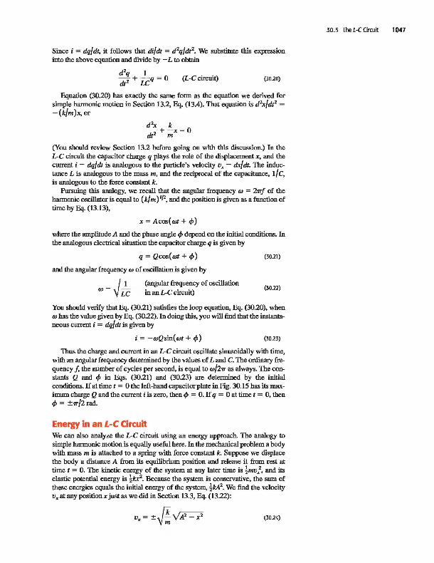
Since i = dq/dt, it follows that di/dt = d 2q/dt2. We substitute this expression into the above equation and divide by - L to obtain
d2q I dt2 + iCq = 0 (L-C circuit) (30.20)
Equation (30.20) has exactly the same form as the equation we derived for simple harmouic motion in Section 13.2, Eq. (13.4). That equation is d2x/dt2 =
-(k/m)x, or
d 2x k dt2 + ,nx = 0
(You should review Section 13.2 before going on with this discussion.) In the L-C circuit the capacitor charge q plays the role of the displacement X, and the current i = dq/dt is analogous to the particle's velocity v. = dx/dt. The inductance L is analogous to the mass m, and the reciprocal of the capacitance, 1/ C, is analogous to the force constant k.
Pursuing this analogy, we recall that the angular frequency CtJ = 2'TrJ of the harmouic oscillator is equal to (k/ m) 1/2, and the position is given as a function of time by Eq. (13.13),
x = Acos(CtJt + c/»
where the amplitude A and the phase angle t/> depend on the iuitial conditions. In the analogous electrical situation the capacitor charge q is given by
q = Qcos(CtJt + t/»
and the angular frequency CtJ of oscillation is given by
(angular frequency of oscillation in an L-C circuit)
(30.21)
(30.22)
You should verify that Eq. (30.21) satisfies the loop equation, Eq. (30.20), when CtJ has the value given by Eq. (30.22). In doing this, you will find that the instantaneous current i = dq/dt is given by
i = -CtJQsin(CtJt + t/» (30.23)
Thus the charge and current in an L-C circuit oscillate sinusoidally with time, with an angular frequency determined by the values of Land C. The ordinary frequency f, the number of cycles per second, is equal to CtJ/2'Tr as always. The constants Q and t/> in Eqs. (30.21) and (30.23) are determined by the iuitial conditions. If at time t = 0 the left-hand capacitor plate in Fig. 30.15 has its maximum charge Q and the current i is zero, then c/> = O. If q = 0 at time t = 0, then t/> = ±'Tr/2rad.
Energy in an L-C Circuit We can also analyze the L-C circuit using an energy approach. The analogy to simple harmouic motion is equally useful here. In the mechanical problem a body with mass m is attached to a spring with force constant k. Suppose we displace the body a distance A from its equilibrium position and release it from rest at time t = O. The kinetic energy of the system at any later time is !mv;, and its elastic potential energy is !kx2
• Because the system is conservative, the sum of these energies equals the iuitial energy of the system, !kA? We find the velocity v. at any position x just as we did in Section 13.3, Eq. (13.22):
v.= ±~VA2_X2 (30.24)
30.5 TheL-CCircuit 1047

1048 CHAPTER 30 Inductance
Table 30.1 Oscillation of a MassSpring System Compared with Electrical Oscillation in an L -C Circuit
Mass-Spring System _____ _
Kinetic energy = ~mvJl:2
Potential energy = ~kx2
!mvJl:2 + !kx2 = !kA2
V. = ±Vk/mVA2 - x2
V. = dx/dt
ru=~ x = Acos(rut + <1»
Inducto,..Capacltor Circuit
Magnetic energy = !Li2
Electric energy = q2/2C
~Li2 + q2/2C = Q2/2C
i = ± Vl[ii:v Q2 _ q2
i = dq/dt
ru=Rc q = Qcos(rut + <1»
The L-C circuit is also a conservative system. Again let Q be the maximum capacitor charge. The magoetic-field energy !Li2 in the inductor at any time corresponds to the kinetic energy !mv2 of the oscillatiog body, and the electricfield energy q2/2C in the capacitor corresponds to the elastic potential energy ! b? of the spring. The sum of these energies equals the total energy Q2/2C of the system:
1 q2 Q2 -Li2 + -2 2C 2C
(30.25)
The total energy in the L-C circuit is constant; it oscillates between the magnetic and the electric forms, just as the constant total mechanical energy in sirople harmonic motion is constant and oscillates between the kinetic and potential forms.
Solving Eq. (30.25) for i, we find that when the charge on the capacitor is q, the current i is
i=±/lW-;f 'hc (30.26)
You can verify this equation by substituting q from Eq. (30.21) and i from Eq. (30.23). Comparing Eqs. (30.24) and (30.26), we see that current i = dq/dt and charge q are related in the same way as are velocity Vx = dx/dt and position x in the mechanical problem.
The analogies between simple harmonic motion and L-C circuit oscillations are summarized in Table 30.1. The striking parallel shown there between mechanical and electrical oscillations is one of many such examples in physics. This parallel is so close that we can solve complicated mechanical and acoustical problems by settiog up analogous electrical circuits and measuring the currents and voltages that correspond to the mechanical and acoustical quantities to be determined. This is the basic principle of many analog computers. This analogy can be extended to damped oscillations, which we consider in the next section. In Chapter 31 we will extend the analogy further to include forced electrical oscillations, which occur in all alternating-current circuits.
An oscillating circuit
A 300-V dc power supply is used to charge a 25-/LF capacitor. After the capacitor is fully charged, it is disconnected from the power supply and connected across a lO-mH inductor. The resistance in the circuit is negligible. (a) Find the frequency and period of oscillation of the circuit. (b) Find the capacitor charge and the circuit current 1.2 ms after the inductor and capacitor are connected.
".Uijil,P' IDENTIFY: Our target variables are the frequency 1 and period T, as well as the values of charge q and current i at a given time f.
SET UP: We are given the capacitance C and the inductance L, from which we can calculate the frequency and period using Eq. (30.22). We find the charge and current using Eqs. (30.21) and (30.23). Iuitially the capacitor is fully charged and the current is zero, as in Fig. 30.14a, so the phase angle is <I> = 0 [seethe discussion that follows Eq. (30.23)].
EXECUTE: (a) The natural angular frequency is
w = ~ = f<1O x 10 3H)\25 x 10 6F)
= 2.0 X 10³ rad/s
The frequency 1 is 1/27T times this:
w 2.0 X 10³ rad/s 1=-2 =-2-ad,--=320Hz
7T 7T r Jcyele
The period is the reciprocal of the frequency:
T= .! = _1_= 3.1 x 1O-3 s= 3.1ms 1320Hz
(b) Since the period of the osci11ation is T = 3.1 ms,t = 1.2ms equals 0.38T; this corresponds to a situation intermediate between

Fig.30.14b (t = T/4) and Fig. 30.14<: (t = T/2). Comparing those figures to Fig. 30.15, we expect the capacitor charge q to be negative (that is, there will be negative charge on the left-hand plate of the capacitor) and the current i to be negative as well (that is, current will be traveling in a counterclockwise direction).
To find the value of q, we use Eq. (30.21). The charge is maximum at t = 0, so '" = 0 and Q = ce = (25 X 1O-6F)(300V) = 7.5 X 10-' C. The charge q at any time is
q = (7.5 X lO-'C)coscut
At time t = 1.2 X 10-' s,
Energy in an oscillating circuit
Consider again the L-C circuit of Example 30.9. 9 (a) Find the magnetic energy and electric energy at t = 0. (b) Find the magnetic energy and electric energy at t = 1.2 ms.
Ij",jii"H' IDENTIFY: This problem asks for the magnetic energy (stored in the inductor) and the electric energy (stored in the capacitor) at two different times during the oscillation of the L-C circuit.
SET UP: From Example 30.9 we know the values of the capacitor charge q and circuit current i for both of the times of interest. We use them to calculate the magnetic energy stored in the inductor, given by UB = ! Li2
, and the electric energy stored in the capacitor, given by UE = q2/2C.
EXECUTE: (a) At t = 0 there is no current and q = Q. Hence there is no magnetic energy, and all the energy in the circuit is in the form of electric energy in the capacitor:
Q2 (7.5 X 10-' C), UE = 2C = 2(25 X 10 6 F) 1.1 J
30.6 The L-R·C Series Circuit 1049
cut = (2.0 X IO'rad/s)(1.2 X 10-' s) = 24rad
q = (7.5 X 10-' C) cos(24 rad) = -5.5 X 10-'C
The current i at any time is
i = -cuQsincut
At time t = 1.2 X 10-' s,
i = -(2.0 X IO'rad/s)(7.5 X 1O-'C)sin(24rad) = -lOA
EVALUATE: Note that the signs of q and i are both negative, as we predicted.
(b) As we mentioned in Example 30.9, t = 1.2 ms corresponds to a situation intermediate between Fig. 30.14b (t = T/4) and Fig. 30.14<: (t = T/2). So we expect the energy to be part magnetic and part electric at this time. From Example 30.9, i = -10 A and q = -5.5 X 10-' C, so
UB = ~Li2 = ~(1O X lO-'H)( -lOA)2 = 0.5 J
q2 (-5.5 X 10-' C)2 U. = 2C = 2(25 X 1O-6F) = 0.6J
EVALUATE: The magnetic and electric energies are the same at t = 3T/S = 0.375T, exactly halfway between the situations in Figs. 30.14b and 30.14<:. The time we are considering here is slightly later and UB is slightly less than UE, as we would expect. We emphasize that at all times, the total energy E = UB + UE has the same value, 1.1 J. An L-C circuit without resistance is a conservative system; no energy is dissipated.
Test Your Understanding of Sedion 30.5 One way to think about the energy stored in an L-C circuit is to say that the circuit elements do positive or negative work on the charges that move back and forth through the circuit. (a) Between stages (a) and (b) in Fig. 30.14, does the capacitor do positive work or negative work on the charges? (b) What kind of force (electric or magnetic) does the capacitor exert on the charges to do this wmk? (c) During this process, does the inductor do positive or negative work on the charges? (d) What kind offorce (electric or magnetic) does the inductor exert on the charges? ..I
30.6 The L-R-C Series Circuit In our discussion of the L-C circuit we assumed that there was no resistance in the circuit. Ths is an idealization, of course; every real inductor has resistance in its windings, and there may also be resistance in the connecting wires. Because of resistance, the electromagnetic energy in the circuit is dissipated and converted to other forms, such as internal energy of the circuit materials. Resistance in an electric circuit is analogous to friction in a mechanical system.
Suppose an inductor with inductance L and a resistor of resistance R are connected in series across the terminals of a charged capacitor, forming an L·R· e series circuit. As before, the capacitor starts to discharge as soon as the circuit
Ad'v PhYSICS
14.2 AC Circuits: The RLC Oscillator (Questions 7-10)

1050 CHAPTER 30 Inductance
30.16 Graphs of capacitor charge as a function of time in an L-R-C series circuit with initial charge Q.
(a) Undenlamped circuit (small resistance R)
q
Q
(b) Critically damped circuit (larger resistance R)
q
:~ (e) Overdamped circuit (very laQ!e resistance R)
q
:~ 30.17 An L-R-C series circuit.
When switch S is in this position, Ihe emf charges Ihe capaciUr.
+t When switch S is moved to this position, Ihe capacitor discharges through Ihe resistor and inductor.
is completed. But because of i 2R losses in the resistor, the magnetic-field energy acquired by the inductor when the capacitor is completely discharged is less than the original electric-field energy of the capacitor. In the same way, the energy of the capacitor when the magnetic field has decreased to zero is still smaller, and so on.
If the resistance R is relatively small, the circuit still oscillates, but with damped harmonic motion (Fig. 30. 16a), and we say that the circuit is underdamped. If we increase R, the oscillations die out more rapidly. When R reaches a certain value, the circuit no longer oscillates; it is critically damped (Fig. 30. 16b). For still larger values of R, the circuit is overdamped (Fig. 30.16c), and the capacitor charge approaches zero even more slowly. We used these same terms to describe the behavior of the analogous mechanicsl system, the damped hannonic oscillator, in Section 13.7.
Analyzing an L-R-C Circuit To analyze L-R -c circuit behavior in detail, we consider the circuit shown in Fig. 30.17. It is like the L-C circuit of Fig. 30.15 except for the added resistor R; we also show the source that charges the capacitor initially. The labeIiug of the positive senses of q and i are the same as for the L-C circuit.
First we close the switch in the upward position, connecting the capacitor to a source of emf e for a long enough time to ensure that the capacitor acquires its final charge Q = ce and any initial oscillations have died out. Then at time t = 0 we flip the switch to the downward position, removing the source from the circuit and placing the capacitor in series with the resistor and inductor. Note that the initial current is negative, opposite in direction to the direction of i shown in the figure.
To find how q and i vary with time, we apply Kirchhoff's loop rule. Starting at point a and going around the loop in the direction abcda, we obtain the equation
. di q -iR - L- - -= 0
dt C
Replacing i with dqldt and rearranging, we get
Note that when R = 0, this reduces to Eq. (30.20) for an L-C circuit.
(30.27)
There are general methods for obtaining solutions of Eq. (30.27). The form of the solution is different for the underdamped (small R) and overdamped (large R) cases. When R2 is less than 4Llc, the solution has the form
(30.28)
where A and ." are constants. We invite you to take the first and second derivatives of this function and show by direct substitution that it does satisfy Eq. (30.27).
This solution corresponds to the underdamped behavior shown in Fig. 30.16a; the function represents a sinusoidal oscillation with an exponentially decaying ~litude. (Note that the exponential factor e -(RJ2L)' is not the same as the factor e- RJL), that we encountered in describing the R-L circuit in Section 30.4.) When R = 0, Eq. (30.28) reduces to Eq. (30.21) for the oscillations in anL-C circuit. If R is not zero, the angular frequency of the oscillation is less than 11 (LcFJ2
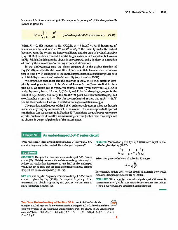
because of the tenn containing R. The angular frequency Cd' of the damped oscillations is given by
(underdarnped L-R-C series circuit) (30.29)
When R = 0, this reduces to Eq. (30.22), Cd = (lILC)1f2. As R increases, Cd'
becomes smaller and smaller. When R2 = 4Llc, the quantity under the radical becomes zero; the system no longer oscillates, and the case of critical damping (Fig. 30.16b) has been reached. For still larger values of R the system behaves as in Fig. 30.16c. In this case the circuit is overdamped, and q is given as a function of time by the sum of two decreasing exponential functions.
In the underdamped case the phase constant ." in the cosine function of Eq. (30.28) provides for the possibility of both an initial charge and an initial current at time t = 0, analogous to an underdarnped harmonic oscillator given both an initial displacement and an initial velocity (see Exercise 30.38).
We emphasize once more that the behavior of the L-R-C series circuit is completely analogous to that of the damped harmonic oscillator studied in Section 13.7. We invite you to verify, for example, that if you start with Eq. (13.41) and substitute q for x, L for m, 1/c for k, and R for the damping constant b, the result is Eq. (30.27). Similarly, the cross-over point between underdamping and overdarnping occurs at b2 = 4km for the mechanical system and at R2 = 4Llc for the electrical one. Can you find still other aspects of this analogy?
The practical applications of the L-R -C series circuit emerge when we include a sinusoidally varying source of emf in the circuit. This is analogous to the forced oscillations that we discussed in Section 13.7, and there are analogous resonance effects. Such a circuit is called an alternating-current (ac) circuit; the analysis of ac circuits is the principal topic of the next chapter.
An underdampecl L-R-C series circuit
30.6 The L-R-C Series Circuit 1051
What resistance R is required (in terms of Land C) to give an L-R-C circuit a frequency that is one-half the undamped frequency?
EXECUTE: We want w' given by Eq. (30.29) to he equal to onehalf of w given by Eq. (30.22):
IDENTIFY: This problem concerns an underdamped L-R-C series circuit (Fig. 30.16a): we want the resistance to be great enough to reduce the oscillation frequency to one-half of the undamped value, but not so great that the oscillator become criticaly damped (Fig. 30.1b) or overdamped (Fig. 30.16c).
SET UP: The angular frequency of an underdamped L-R-C series circuit is given by Eq. (30.29); the angular frequency of an undamped L-C circuit is given by Eq. (30.22). We use these to solve for the target variable R.
~l[l "'Vu: - 4iJ = z"VLc
When we square both sides and solve for R, we get
R=fJ For example, adding 35 n to the circuit of Example 30.9 would reduce the frequency from 320 Hz to 160 Hz.
EVALUATE: The circuit becomes critically damped with no oscillations when R = V4iJC. Our result for R is smaller than that, as it should be; we want the circuit to be underdamped.
Test Your understaii"ding of Sedion 30.6 An L-R-C series circuit ~) includes a 20-0 resistor. At t = 0 the capacitor charge is 2.0 p.C. for which of the ~ following values of the inductance and capacitance will the charge on the capacitor not oscillate? (i) L = 3.0 p.H, C = 6.0 p.F; (ii) L = 6.0 p.H, C = 3.0 p.F; (ill) L = 3.0 p.H, C = 3.0p.F.
I
CHAPTER 30 SUMMARY
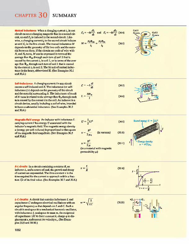
Mutual indudllnce When a changing current i, in one circuit causes a changing magnetic lIux in a second circuil, an emf £2 is induced in Ihe second circuit. Likewise, a changing current i2 in Ihe second circuit induces an emf £, in Ihe first circuit. The mutual inductance M depends on Ihe geometry of Ihe two coils and Ihe material between Ihem. If 1he circuits are coils of wire wilh N, and N2 tums, M can be expressed in terms of Ihe average lIux <l>B2 through each tum of coil 2 lhat is caused by Ihe currenti1 in coil 1, or in terms of Ihe average lIux <l>m through each tum of coil 1 lhat is caused by Ihe current i2 in coil 2 The SI unit of mutual inductance is Ihe henry, abbreviated H. (See Examples 30.1 and 30.2)
Self-indudllnce A changing current i in any circuit causes a self-induced emf £. The inductance (or selfinductance) L depends on Ihe geometry of Ihe circuit and Ihe material surrounding it. The inductance of a coil of N tums is related to Ihe average lIux <l>B through each tum caused by Ihe current i in Ihe coil. An inductur is a circuit device, usually including a coil of wire, intended to have a substantial inductance. (See Examples 30.3 and 30.4.)
Magnetlo-field energy An inductor wilh inductance L carrying current I has energy U associated wilh Ihe inductor's magnetic field. The magnetic energy density u (energy per uuit volume) is proportional to 1he square of Ihe magnetic field magnitude. (See Examples 30.5 and 30.6.)
R-L circuits In a circuit containing a resistor R, an inductor L, and a source of emf, Ihe growlh and decay of current are exponemial. The time constant T is Ihe time required for Ihe current to approach within a fraction lIe of its final value. (See Exantples 30.7 and 30.8.)
L-C circuits: A circuit lhat contains inductance L and capacitance C undergoes electrical oscillations wilh an angular frequency co lhat depends on L and C. Such a circuit is analogous to a mechanical harrnouic oscillator, wilh inductance L analogous to mass m, Ihe reciprocal of capacitance llc to force constant k, charge q to displacement x, and current i to velocity VX • (See Exam-ples 30.9 and 30.10.)
1052
di1 di £2 = -Mdt and £, = -M d: (30.4)
di £= -L
dt
N<l>B L=-
i
U=!U2
2
B2 U = 2: P.o (in vacuum)
B2 u=-
2p. (in a material wilh magnetic permeability p.)
L T=-
R
(30.7)
(30.6)
(30.9)
(30.10)
(30.11)
(30.16)
(30.22)
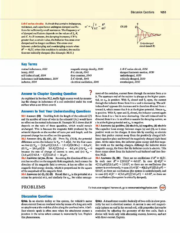
L-R-C series circuits: A circuit that contains inductance, resistance, and capacitance undergoes damped oscillations for sufficiently small resistance. The frequency co' of damped oscillations depends on the values of L, R, and C. As R increases, the damping increases; if R is greater than a certain value, the behavior becomes overdamped and no longer oscillates. The cross-over between underdamping and overdamping occurs when R2 = 4L/ C; when tltis condition is satisfied, the oscillations are critically damped. (See Example 30.11.)
Key Terms
(30.29)
Discussion Questions 1053
q
Q~, ' -- - - - I
a U:~~~d--circuit (small R)
mutual inductance, 1031 henry, 1032 self-induced emf, 1034
magnetic energy density, 1040 R-L circuit, 1041
L-R-C series circuit, 1050 damped harmonic motion. 1050 underdamped, 1050 time constant, 1043
DC circuit, 1045 inductance (self-inducIance), 1034 inductor, 1034 electrical oscillation, 1046
critically damped, 1050 ovenlamped, 1050
Answer to Chapter Opening Question 7 . As explained in Section 30.2, traffic ligbt sensors work by measuring the change in inductance of a cnil embedded under the road surface when a car drives over it.
Answers to Test Your Understanding Questions 30.1 Answer: (iii) Doubling both the length of the solennid {l} and the number of turns of wire in the solenoid (N,) would have no effect on the mutual inductance M. Example 30.1 shows that M depends on the ratio of these quantities, which would remain unchanged. This is because the magnetic field produced by the solenoid depends on the number of turns per unit length, and the proposed change has no effect on tltis quantity. 30.2 Answer: (iv), (i), (iii), (ii) From Eq. (30.8), the potential difference across the inductor is V"" = L di/dt. For the four cases we find (i) V"" = (20p,H){20A - 1.0A)/{0.50s) = 4.0p,V; (ii)V"" = (4.0p,H){O-3.0A)/{2.0s) = -6.0p,V;(iii) V.., = 0 because the rate of change of current is zero; and (iv) V"" =
(1.0 p,H){4.0 A - 0)/{0.25 s) = 16p,V. 30.3 Answers: (a) yes, (b) no Reversing the direction of the current has no effect on the magnetic field magnitude, but it causes the direction of the magnetic field to reverse. It has no effect on the
magnetic-field energy density, which is proportional to the square of the magnitude of the magnetic field. 30.4 Answers: (a) (i), (b) (ii) Recall that v"" is the potential at a minus the potential at b, and similarly for Vb<' For either arrange-
ment of the switches, current flows through the resistor from a ro b. The upstream end of the resistor is always at the higher potential, so v"" is positive. With S, closed and S2 open. the current through the inductor flows from b to c and is increasing. The selfinduced emf opposes tltis increase and is therefore directed from c toward b, which means that b is at the higher potential. Hence vb<
is positive. With S, open and S2 closed, the inductor current again flows from b to c but is now decreasing. The self-induced emf is directed from b to c in an effort to sustain the decaying current, so c is at the higher potential and vb< is negative. 30.5 Answers: (a) positive, (b) electric, (c) negative, (d) electric The capacitor loses energy between stages (a) and (b), so it does positive work on the charges. It does tltis by exerting an electric force that pushes current away from the positively charged lefthand capacitor plate and toward the negatively charged right-hand plate. At the same time, the inductur gains energy and does negative work on the moving charges. Althougb the inductor stures magnetic energy, the force that the inductor exerts is electric. This force comes about from the inductur's self-induced emf (see Section30.2). 30.6 Answers: (i), (iii) There are no oscillations if R2 2: 4L/C. In each case R2 = (200)' = 4.002• In case (i)4L/C = 4{3.0p,H)/{6.0p,F) = 2.002
, so there are no oscillations (the system is overdamped); in case (ii) 4L/C = 4{ 6.0 p,H )/(3.0 p,F) =
8.0 0 2, so there are oscillations (the system is undenlamped); and in case (iii) 4L/C = 4{3.0p,H)f{3.0 p,F) = 4.002
, so there are no oscillations (the system is critically damped).
PROBLEMS For instructor-ilssigned homework, go to www.masteringphysics.com e Discussion Questions Q:s0.1. In an electric trolley or bus system, the vehicle's motur draws current from an overhead wire by means of a long arm with an attachment at the end that slides along the overhead wire. A brilliant electric spark is often seen when the attachment crosses a junction in the wires where contact is momentarily lost. Explain tltis phenomenon.
Q:sD.2. A transformer consists basically of two coils in close proxintity but not in electrical contact. A current in one coil magnetically induces an emf in the second coil, with properties that can be controlled by adjusting the geometry of the two coils. Such a device will work ouly with alternating current, however, and not with direct current. Explain.

1054 CHAPTER 30 Inductance
Q3CJ.3. In Fig. 30.1, if coil 2 is tumed 90" so that its axis is vertical, does the mutual inductance increase or decrease? Exp\ain. QlO.4. 'The tightly wound toroidal solenoid is one of the few configurations for which it is easy to calculate self-inductance. What features of the toroidal solenoid give it this simplicity? Q30.5. Two identical, closely wound, circular coils, each having self-inductance L, are placed next to each other, so that they are coaxial and almost touching. If they are connected in series, what is the self-inductance of the combination? What if they are connected in parallel? Can they be connected so that the total inductance is zero? Explain. Q30.6. Two closely wound circular coils have the same number of tums, but one has twice the radius of the othe~ How are the selfinductances of the two coils related? Explain your reasoning. QlO.7. You are to make a resistor by winding a wire around a cylindrical form. To make the inductance as small as possible, it is proposed that you wind half the wire in one direction and the other half in the opposite direction. Would this achieve the desired result? Why or why not? QlO.8. For the same magnetic field strength B, is the energy density greater in vacuum or in a magnetic material? Explain. Does Eq. (30.11) imply that for along solenoid in which the current is I the energy stored is proportional to l//L? And does this mean that for the same current less energy is stored when the solenoid is filled with a ferromagnetic material rather than with air? Explain. Q30.9. In Section 30.5 Kirchhoff's loop rule is applied to an L-C circuit where the capacitor is initially fully charged and the equation -L di/dt - q/C = 0 is derived. But as the capacitor starts to discharge, the current increases from zero. 'The equation says Ldi/dt = -q/C, so it says Ldi/dt is regative. Explain how Ldi/dt can be negative when the cnrrent is increasing. Q30.1O. In Section 305 the relationship i = dq/dt is used in deriving Eq. (30.20). But a flow of current corresponds to a decrease in the charge on the capacitor. Explain, therefore, why this is the correct equation to use in the derivation, rather than i = -dq/dt. Q30.11. In the R-L circuit shown in Fig. 30.11, when switch S, is closed. the potential v"" changes suddenly and discontinuously, but the current does not. Explain why the voltage can change suddenly but the current can't. Q30.ll. In the R-L circuit shown in Fig. 30.11, is the current in the resistor always the same as the cnrrent in the inductor? How do you know? QlO.13. Suppose there is a steady current in an inductor. If you attempt to reduce the current to zero instantaneously by quickly opening a switch, an arc can appear at the switch contacts. Why? Is it physically possible to stop the current instantaneously? Bxplain. Q30.14. In an R-LC circuit, what criteria could be used to decide whether the system is ovenlamped or underdamped? For example, could we compare the maximum energy stored during one cycle to the energy dissipated during one cycle? Explain
Exercises Section 30.1 Mutual Inductance 30.1. Two coils have mutual inductance M = 3.25 X 10⁻⁴ H. The current i, in the first coil increases at a unifOlm rate of 830 A/s. (a) What is the magnitude of the induced emf in the second coil? Is it constant? (b) Suppose that the cnrrent described is in the second coil rather than the first What is the magnitude of the induced emf in the fust coil? 30.2. Two coils are wound around the same cylindrical form, like the coils in Example 30.1. When the current in the first coil is decreasing at a rate of -0.242 A/s, the induced emf in the second
coil has magnitude 1.65 X 10⁻³ V. (a) What is the mutual inductance of the pair of coils? (b) If the second coil has 25 turns, what is the flux through each turn when the cnrrent in the first coil equals 1.20 A? (c) If the current in the second coil increases at a rate of 0.360 A/s, what is the magnitude of the induced emf in the first coil? 30.3. From Eq. (30.5) I H = I Wh/A, and from Eq. (30.4) 1 H = 1 n . s. Show that these two definitions are equivalent. 30.4. A solenoidal coil with 25 turns of wire is wound tightly around another coil with 300 turns (see fuample 30.1). The inner solenoid is 25.0 cm long and has a diameter of 2.00 cm. At a certain time, the current in the inner solenoid is 0.120 A and is increasing at a rate of 1.75 X 10' A/s. For this time, calculate; (a) the average magnetic flux through each tum of the inner solenoid; (b) the mutual inductance of the two solenoids; (c) the emf induced in the outer solenoid by the changing current in the inner solenoid. JO.5. Two toroidal solenoids are wound around the same form so that the magnetic field of one passes through the turns of the other. Solenoid I has 700 turns, and solenoid 2 has 400 turns. When the current in solenoid I is 6.52 A, the average flux through each tum of solenoid 2 is 0.0320 Wh. (a) What is the mutual inductance of the pair of solenoids? (b) When the current in solenoid 2 is 2.54 A, what is the average flux through each turn of solenoid I?
Section 30.2 Self-Inductance and Inductors 30.6. A toroidal solenoid has 500 turns, cross-sectional area 6.25 cm2
, and mean radius 4.00 cm. (a) Calcualte the coil's selfinductance. (b) If the current decreases uniformly from 5.00 A to 2.00 A in 3.00 ms, calculate the self-induced emf in the coil. (c) The current is directed from terminal a of the coil to terminal b. Is the direction of the induced emf from a to b or from b to a? 30.7. At the instant when the current in an inductor is increasing at a rate of 0.0640 A/s, the magnitude of the self-induced emf is 0.0160 V. (a) What is the inductance of the inductor? (b) If the inductor is a solenoid with 400 turns, what is the average magnetic flux through each tum when the current is 0.720 A? 30.8. When the current in a toroidal solenoid is changing at a rate of 0.0260 A/s, the magnitude of the induced emf is 12.6 mY. When the current equals 1.40 A, the average flux through each tum of the solenoid is 0.00285 Wh. How many turns does the solenoidhave? 30.9. The inductor in fig. 30.18 has inductance 0260 H and carries a current in the direction shown that is deaeasing at a uniform rate, di/dt = -0.0180 A/s. (a) Find the self-induced emf. (b) Which end of the inductor, a or b, is at a higher potential? 30.10. The inductor shown in Fig. 30.18
Figure 30.18 Exercises 30.9 and 30.10.
? ~ aLb
has inductance 0.260 H and carries a current in the direction shown. The current is changing at a constant rate. (a) The potential between points a and b is V"" = 1.04 V, with point a at higher potential. Is the current increasing or decreasing? b) If the current at t = 0 is 12.0 A, what is the current at t = 200 s? 30.11. Inductance of a Solenoid. A long, straight solenoid has N tums, uniform cross-sectional area A, and length I. Show that the inductance of this solenoid is given by the equation L = /LoAN'/I. Assume that the magnetic field is uniform inside the solenoid and zero outside. (Your answer is approximate because B is actually smaller at the ends than at the center. For this reason, your answer is actually an upper liroit on the inductance.)

Section 30.3 Magnetic-Field Energy 30.12. An inductor used in a dc power supply has an inductance of 12.0 H and a resistance of 180 O. It carries a current of 0.300 A. (a) What is the energy stored in the magnetic field? (b) At what rate is thermal energy developed in the inductor? (c) Does your answer to part (b) mean that the magnetic-field energy is decreasing with time? Explain. 30.13. An air-filled toroidal solenoid has a mean radius of IS.0 cm and a cross-sectional area of S.OO cm2. When the current is 120 A, the energy stored is 0.390 I. How many turns does the winding have? 30.14. An air-filled toroidal solenoid has 300 turns of wire, a mean radius of 12.0 cm, and a cross-sectional area of 4.00 cm2. If the current is S.OO A, calculate: (a) the magnetic field in the solenoid; (b) the self-inductance of the solenoid; (c) the energy stored in the magnetic field; (d) the energy density in the magnetic field. (e) Check your answer for part (d) by dividing your answer to part (c) by the volume of the solenoid. 30.15. A solenoid 25.0 cm long and with a cross-sectional area of O.SOO cm2 contains 400 turns of wire and carries a current of 80.0 A. Calculate: (a) the magnetic field in the solenoid; (b) the energy density in the magnetic field if the solenoid is filled with air; (c) the total energy contained in the coil's magnetic field (assume the field is uniform); (d) the inductance of the solenoid. 30.16. It has been proposed to use large inductors as energy storage devices. (a) How much electrical energy is converted to light and thermal energy by a 200-W light bulb in one day? (b) If the amount of energy calculated in part (a) is stored in an inductor in which the current is 80.0 A, what is the inductance? 30.17. Starting from Eq. (30.9), derive in detail Eq. (30.11) for the energy density in a toroidal solenoid filled with a magnetic material. 30.1B. It is proposed to store 1.00 kW • h = 3.60 X 10⁶ I of electrical energy in a uniform magnetic field with magnitude 0.600 T. (a) What volume (in vacuum) must the magnetic field occupy to store this amount of energy? (b) If instead this amount of energy is to be stored in a volume (in vacuum) equivalent to a cube 40.0 cm on a side, what magnetic field is required?
Section 30.4 The R-L Circuit 30.19. An inductor with an inductance of 2.S0 H and a resistance of 8.00 0 is connected to the terminals of a battery with an emf of 6.00 V and negligible internal resistance. Find (a) the initial rate of increase of current in the circuit; (b) the rate of increase of current at the instant when the current is O.SOO A; (c) the current 0.250 s after the circuit is closed; (d) the final steady-state current. 30.20. A IS.0-O resistor and a coil are connected in series with a 6.30-V battery with negligible internal resistance and a closed switch. (a) At 200 IDS after the switch is opened the current has decayed to 0.210 A. Calculate the inductance of the coil. (b) Calculate the time constant of the circuit. (c) How long after the switch is closed will the current reach 1.00% of its original value? 30.21. A 3S.0-V battery with negligible internal resistance, a SO.O-O resistor, and a 1.25-mH inductor with negligible resistance are all connected in series with an open switch. The switch is suddenly closed. (a) How long after closing the switch will the current through the inductor reach one-half of its maximum value? (b) How long after closing the switch will the energy stored in the inductor reach one-half of its maximum value? 30.n. In Fig. 30.11, switch S, is closed while switch S2 is kept open. The inductance is L = O.l1S H, and the resistance is R = 120 O. (a) When the current has reached its final value, the energy stored in the inductor is 0.260 I. What is the emf e of the battery? (b) After the current has reached its final value, S, is
Exercises 1055
opened and S2 is closed. How much time does it take for the energy stored in the inductor to decrease to 0.130 I, half the original value? 30.D. Show that LIR has units of time. 30.24. Write an equation corresponding to Eq. (30.13) for the current shown in Fig. 30.11 just after switch S2 is closed and switch S, is opened, if the initial current is 10• Use integration methods to verify Eq. (30.18). 30.25. In Fig. 30.11, suppose that e = 60.0 V, R = 2400, and L = 0.160 H. With switch S. open, switch S, is left closed until a constant current is established. Then S. is closed and S, opened, taking the battery out of the circuit. (a) What is the initial current in the resistor, just after S2 is closed and S, is opened? (b) What is the current in the resistor at t = 4.00 X 10⁻⁴ s? (c) What is the potential difference between points b and c at t = 4.00 X 10⁻⁴ s? Which point is at a higher potential? (d) How long does it take the current to decrease to half its initial value? 30.26. In Fig. 30.11, suppose that e = 60.0 V, R = 2400, and L = 0.160 H. Initially there is no current in the circuit. Switch S2 is left open, and switch S, is closed. (a) lust after S, is closed, what are the potential differences v"" and Vbc? (b) A long time (many time constants) after S, is closed, what are v"" and v",? (c) What are v"" and Vbc at an intermediate time when i = o.ISOA? 30.27. Refer to Exercise 30.19. (a) What is the power input to the inductor from the battery as a function of time if the circuit is completed at t = O? (b) What is the rate of dissipation of energy in the resistance of the induclOr as a function of time? (c) What is the rate at which the energy of the magnetic field in the inductor is increasing, as a function of time? (d) Compare the results of parts (a), (b), and (c).
Section 30.5 The L -C Circuit 30.26. A 20.0-/LF capacitor is charged by a IS0.0-V power sopply, then disconnected from the power and connected in series with a 0.280-mH inductor. Calculate: (a) the oscillation frequency of the circuit; (b) the energy stored in the capacitor at time t = 0 ms (the moment of connection with the inductor); (c) the energy stored in the inductor alt = 1.30 IDS.
30.26. A 7.S0-nF capacitor is charged op to 12.0 V, then disconnected from the power supply and connected in series through a coil. The period of oscillation of the circuit is then measured to be 8.60 X lO-s s. Calculate: (a) the inductance of the coil; (b) the maximum charge on the capacitor; (c) the total energy of the circuit; (d) the maximum current in the circuit. 30.30. A 18.0-/LF capacitor is placed across a 22.S-V battery for several seconds and is then connected across a 12.O-mH inductor that has no appreciable resistance. (a) After the capacitor and inductor are connected together, find the maximum current in the circuit. When the current is a maxintum, what is the charge on the capacitor? (b) How long after the capacitor and inductor are connected together does it take for the capacitor to be completely discharged for the first time? For the second time? (c) Sketch graphs of the charge on the capacitor plates and the current through the inductor as functions of time. 30.31. L-C Oscillations. A capacitor with capacitance 6.00 X lO-s F is charged by connecting it to a 12.0-V battery. The capacitor is disconnected from the battery and connected across an inductor with L = I.S0 H. (a) What are the angular frequency co of the electrical oscillations and the period of these oscillations (the time for one oscillation)? (b) What is the initial charge on the capacitor? (c) How much energy is initially stored in the capacitor? (d) What is the charge on the capacitor 0.0230 s after the connection to the inductor is made? Interpret the sign of your answer.

1056 CHAPTER 30 Inductance
(e) At the time given in part (d), what is the current in the indueror? Intezpret the sign of your answer. (f) At the time given in part (d). bow much electrical e!1eQlY is srored in the capacitor and bow much is srored in the inductor? 30.32. A Radio 'l\ming Circuit. The minimum capacitance of a variable capacitor in a radio is 4.18 pF. (a) What is the inductance of a coil connected ro this capacitor if the oscillation frequency of the L-C circuit is 1600 X lO3 Hz, corresponding ro one end of the AM radio broadcast band. when the capacitor is set ro its minimum capacitance? (b) The frequency at the other end of the broadcast band is 540 X lO3 Hz. What is the maximum capacitance of the capacitor if the oscillation frequency is adjustable over the range of the broadcast band? 30.33. An Ire circuit containing an 8O.O-mH inductor and a 1.25-nF capacitor oscillates with a maximum current of 0.7SO A. Calculate: (a) the maximum charge on the capacitor and (b) the oscillation frequency of the circuit. (c) Assuming the capacitor had its maximum charge at time t = 0, calculate the enetgy stored in the inductor after 2.50 ms of oscillation. 30.34. In an L-C circuit, L = 85.0 mH and C = 3.20 ",F. During the oscillations the maximum current in the inductor is 0.850 mA. (a) What is the maximum charge on the capaciror? (b) What is the magnitude of the charge on the capacitDr at an instant when the current in the inducror has magnitude 0.500 mA? 30.35. (a) Using Eqs. (30.21) and (30.23) for an L-C circuit, write expressions fur the energy stored in the capacitor as a function of time and for the enetgy stored in the inductor as a function of time. (b) Using Eq. (30.22) and the trigonometric identity siJilx + cos2x = 1, show !hat the total energy in the Ire circuit is constant and equal to Q2/2C. 3O.l6. Show that the differential equation ofEq. (30.20) is satisfied by thefunctionq = Qcos(tuI +.,,), with 61 given by I/ViC.
30.37. Show that ViC has units of time.
Section 30.6 The L -R-C Series Circuit 30.36. For the circuit of FIg. 30.17, let C = 15.0 nF L = 22 mH and R = 7S.0 n (a) Calculate the oscillation freque~y of the cir~ cuit once the capacitor bas been charged and the switch bas been connected to point a (b) How long will it take for the amplitude of the oscillation to decay to lO.O% of its original value? (c) What value of R would result in a critically damped circuit? 30.31. (a) In Eq. (13.41). substitute q fur x, L for m. l/C for k, and R fur the damping constant b. Show that the result is Eq. (30.27). (b) Make these same substitutions in Eq. (13.43) and show that Eq. (30.29) results. (c) Make these same substitutions inEq. (13.42) and show that Eq. (30.28) results. 30.46. (a) Take first and second derivatives with respect to time of q given in Eq. (30.28), and show that it is a solution of Eq. (30.27). (b) At t = 0 the switch shown in Fig. 30.17 is thrown so that it connects points d and a; at this time, q = Q and i = dq/dt = O. Show that the constants ." and A in Eq. (30.28) arc given by
tan." = R and A=..JL 2LV (l/Le) - (R2/4L2 ) cos<l>
30.41. An L-R-C circuit has L = 0.4S0 H. C = 250 X lO-' F, and resistance R. (a) What is the angu1ar frequency of the circuit when R = O? (b) What value must R have to give a S.O% decrease in angu1ar frequency compared to the value calculated in part (a)? 3D.42. SbowthatthequantityVi[Chasunitsofrcsislance(ohms).
Problems 30.43. One solenoid is centered inside another. The outer one has a length of SO.O cm and contains 67SO coils, while the coaxial inner solenoid is 3.0 cm long and 0.120 cm in diameter and contains IS coils. The current in the outer solenoid is changing at 37.S A/s. (a) what is the mutual inductance of !hese solenoids? (b) Find the emf induced in the innner solenoid. 30.44. A coil bas 400 turns and self-inductance 3.50 mHo The current in the coil varies with time according to i =
(680mA)cos(wt/0.0250s). (a) What is the maximum emf induced in the coil? (b) What is the maximum average flux through each tum of the coil? (c) At t = 0.0180 s. what is the magnitude of the induced emf? 30.45. A Differenliatlng Clr- Figure 30.19 Problem 30.45 coil. The current in a resis-tanceless inductor is caused to vary with time as shown in the graph of Fig. 3Q.19. (a) Sketch the pattern that would be
oVvv'v , observed on the screen of an oscilloscope connected to the terminals of the inducror. (The oscilloscope spot sweeps horizontally across the screen at a constant speed. and its vertical deflection is proportional to the potential difference between the inductor terminals.) (b) Explain why a circuit with an inductor can be described as a "differentiating circuit." 30.46. A 0.250-H inductor carries a time-varying current given by the expression i = (l24mA)cos[(24O'lf/s) t]. (a) Find an expression for the induced emf as a function of time. Graph the current and induced emf as functions of time for t = 0 to t = ~ S.
(b) What is the maximum emf? What is the current wben the induced emf is a maximum? (c) What is the maximum current? What is the induced emf when the current is a maximum? 30.47. Inductors in Series BDd Parallel. You arc given two inductors, one of self-inductance L. and the other of self-inductance L 2• (a) You connect the two inductors in series and arrange them so that their mutual inductance is negligible. Show that the equivalent inductance of the combination is L .. = L. + L 2• (b) You now conneet the two inductors in parallel. again arranging them so that their mutual inductance is negligible. Show that the equivalent inductance of the combination is L.., = (I/L. +l/Lz)-·. (Hint: For ei!her a series or a parallel combination, the potential difference across the combination is L .. (di/dt). where i is the current through the combination. For a parallel combinatioo, i is the sum of the currents through the two inductors.) 30.46. A Coaxial Cable. A small solid conductor with radius a is supported by insulating. nonmagnetic disks on the axis of a thinwalled tube with inner radius b. The inner and outer conductors carry equal currents i in opposite directions. (a) Use Ampere's law to find the magnetic field at any point in the volume between the conductors. (b) Write the expression fur the flux diPB through a narrow strip of length I parallel to the axis, of width dr, at a distance T from the axis of the cable and lying in a plane containing the axis. (c) Integrate your expression from part (b) over the volume between the two conductors to find the total flux produced by a current i in the central conductor. (d) Show that the inductance of a lenglh I of the cable is
L = ':Iu(~) (e) Use Eq. (30.9) [Q calculate the enetgy stored in the magnetic field for a length I of the cable.

30.46. Consider the coaxial cable of Problem 30.48. The conductors carry equal currems i in opposite directions. (a) Use Ampere's law to find the magnetic field at any point in the volume between the conductors. (b) Use the energy density for a magnetic field, Eq. (30.10), to calculate the energy stored in a thin, cylindrical shell between the two conductors. Let the cylindrical shell have inner radius T, outer radius T + dr, and length I. (c) integrate your result in part (b) over the volume between the two conductors to find the total energy stored in the magnetic field for a length 1 of the cable. (d) Use your result in part (c) and Eq. (30.9) to calculate the inductance L of a length 1 of the cable. Compare your result to L calculated in part (d) of Problem 30.48. 30.50. A toroidal solenoid has a mean radius T and a cross-sectional area A and is wound unifonnly with N, tums. A second toroidal solenoid with N2 tums is wound unifonnly around the first. The two coils are wound in the same direction. (a) Derive an expression for the inductance LI when ouly the first coil is used and an expression for L2 when ouly the second coil is nsed. (b) Show that M 2 =L,L2•
30.51. (a) What would have to be the self-inductance of a solenoid for it to store 10.0 I of energy when a 1.50-A current runs throught it? (b) If this solenoid's cross-sectional diameter is 4.00 cm, and if you could wrap its coils to a density of 10 coils/mm. how long would the solenoid be? (See Exercise 30.11.) Is this a realistic length for ordinary laboratory use? 30.52. An inductor is connected to the terminals of a battery that has an emf of 120 V and negligible internal resistance. The current is 4.86 rnA at 0.725 ms after the connection is completed. After a long time the current is 6.45 rnA. What are (a) the resistance R of the inductor and (b) the inductance L of the inductor? 30.53. Continuation of Exercises 30.111 and 30.27. (a) How much energy is stored in the magnetic field of the inductor one time constant after the battery has been connected? Compute this both hy integrating the expression in Exercise 30.27(c) and by using Eq. (30.9), and compare the results. (b) Integrate the expression obtained in Exercise 30.27(a) to find the total energy supplied by the battery during the time interval considered in part (a). (c) Integrate the expression obtained in Exercise 30.27(b) to find the total energy dissipated in the resistance of the inductor during the same time period. (d) Compare the results obtained in parts (a), (b), and (c). 30.54. Continuation of Exercise 30.25. (a) What is the total energy initially stored in the inductor? (b) Att = 4.00 X 10⁻⁴ s, at what rate is the energy stored in the inductor decreasing? (c) At t = 4.00 X 10⁻⁴ s, at what rate is electrical energy being converted into thermal energy in the resistor? (d) Obtain an expression for the rate at which electrical energy is being converted into thermal energy in the resistor as a function of time. Integrate this expression from t = 0 to t = 00 to obtain the total electrical energy dissipated in the resistor. Compare your result to that of part (a). 30.55. The equation preceding Eq. (30.27) may be converted into an energy relationship. Multiply both sides of this equation by -i = -dq/dt. The first term then becomes i 2R. Show that the second term can be written as d(!Li2)/dt, and that the third term can be written as d( q2/2C)/dt. What does the resulting equation say about energy conservation in the circuit? 30.58. A 5.00-pF capacitor is initially chmged to a potential of 16.0 V. It is then connected in series with a 3.75-mH inductor. (a) What is the total energy stored in this circuit? (b) What is the maximum current in the inductor? What is the charge on the capacitor plates at the instant the current in the inductor is maximal?
Problems 1057
30.57. An Electromagnetic Car Alarm. Your latest invention is a car alarm that produces sound at a particularly annoying frequency of 3500 Hz. To do this, the car-alarm circnitry must produce an alternating electric current of the same frequency. That's why your design includes an inductor and a capacitor in series. The maximum voltage across the capacitor is to be 12.0 V (the same voltage as the car battery). To produce a sufficiently loud sound, the capacitor must store 0.0160 I of energy. What values of capacitance and inductance should you choose for your car-alarm circnit? 30.58. An L-C circnit consists of a 60.O-mH inductor and a 250-",F capacitor. The initial charge on the capacitor is 6.00 ",C, and the initial current in the inductor is zero. (a) What is the maximum voltage across the capacitor? (b) What is the maximum current in the inductor? (c) What is the maximum energy stored in the inductor? (d) When the current in the inductor has half its maximum value, what is the charge on the capacitor and what is the energy stored in the inductor? 30.58. Solar Magnetic Energy. Magnetic fields within a sunspot can be as strong as 0.4 T. (By comparison, the earth's magnetic field is about 1/10,000 as strong.) Sunspots can be as large as 25,000 km in radius. The material in a sunspot has a density of about 3 X 10⁻⁴ kg/m'. Assume", for the sunspot material is "'0' If 100% of the magnetic-field energy stored in a sunspot could be used to eject the sunspot's material away from the sun's surface, at what speed would that material be ejected? Compare to the sun's escape speed, which is about 6 X 10' m/s. (Hint: Calcualte the kinetic energy the magnetic field could sopp1y to 1 m' of sunspot material.) 30.60. While studying a coil of Figure 30.20 Problem 30.60. unknown inductance and inter-na1 resistance, you connect it in series with a 25.0-V battery and a ISO-a resistor. You then place an oscilloscope across one of these circnit elements and use the oscilloscope to measure the voltage across the circuit element as a function of time. The
25t= ~ 20 ~ 15
~1O 5 o
0.5 1.0 1.5 2.0 2.5
Time(ms)
resultis shown in Fig. 30.20. (a) Across which circuit element (coil or resistor) is the oscilloscope connected? How do you know this? (b) Find the inductance and the intemal resistance of the coil. (c) Carefully make a quantitative sketch showing the voltage versus time you would observe if you put the oscilloscope across the other circnit element (resistor or coil). 30.61. In the lab, you are trying Figure 30.21 Problem 30.61. to find the inductance and inter-na1 resistance of a solenoid. You place it in series with a battery of negligible internal resistance, a 10.0-,0, resistor, and a switch. You then put an oscilloscope across one of these circuit elements to measure the voltage across that circnit element as a function of time. You close the
~: 5°b >",20
10
o 0.5 6.0 12.0 18.0
Time(ms)
switch, and the oscilloscope shows voltage versus time as shown in Fig. 30.21. (a) Across which circuit element (solenoid or resistor) is the oscilloscope connected? How do you know this? (b) Why doesn't the graph approach zero as t .... oo? (c) What is the emf of the battery? (d) Fmd the maximum current in the circuit. (e) What are the internal resistance and self-inductance of the solenoid?

1058 CHAPTER 30 Inductance
30.62. In the circuit shown in Figure 30.22 Problem 30.62. Fig. 30.22, find the reading in each ammeter and voltmeter (a) just after switch S is closed and (b) after S has been closed a vel)' long time. 30.63. In the circuit shown in Fig. 30.23, switch S is closed at time r = 0 with no charge initially on the capacitor. (a) Fmd the reading of each ammeter and each voltmeter just after S is closed. (b) Find the reading of each meter after a long time has elapsed. (c) Find the maximum charge on the capacitor. (d) Draw a qualitative graph of the reading of voltmeter V 2 as a function of time.
Figure 30.23 Problem 30.63.
30.64. In the circuit shown in Figure 30.24 Fig. 30.24 the battel)' and the inductor Problem 30.64. have no appreciable internal resist-ance and there is no current in the circuit. After the switch is closed, find the readings of the ammeter (A) and voltmeters (V, and V2) (a) the instant after the switch is closed and (b) after the switch has been closed for a vel)' long time. (c) Which answers in parts (a) and (b) would change if the inductance were 24.0 rnH instead? 30.65. In the circuit shown in Fig. 30.25, switch S is closed at time r = O. (a) Find the reading of each meter just after S is closed. (b) What does each meter read long after S is closed?
Figure 30.25 Problem 30.65.
30.66. In the circuit shown in Fig. 30.26, switch S has been closed for a long enough time so that the current reads a steady 3.SO A. Suddeuly, switch S2 is closed and S, is opened at the same instant. (a) What is the maximum charge that the capacitor will receive? (b) What is the current in the inductor at this time?
Figure 30.26 Problem 30.66.
'~' ~4=~~ 30.67. In the circuit shown in Fig. 30.27, e = 60.0 V, R, = 40.0 n, R2 = 25.0 n, and L = 0.300 H. Switch S is closed at r = 0. lust after the switch is closed, (a) what is the potential difference v tJb across the resistor R,; (b) which point, a or b, is at a higher potential; (c) what is the potential difference Vcd across the inductor L; (d) which point, c or
Figure 30.27 Problems 30.67, 30.68, and 30.75.
s,g~1 a b
R,
R2 C L d
d, is at a higher potential? The switch is left closed a long time and then opened. lust after the switch is opened, (e) what is the potential difference v"" across the resistor R,; (f) which point, a or b, is at a higher potential; (g) what is the potential difference v cd across the inductor L; (b) which point, c or d, is at a higher potential? 30.68. In the circoit shown in Fig. 30.27, e = 60.0 V, R, = 40.0 n, R2 = 25.0 n, and L = 0.300 H. (a) Switch S is closed. At some time t afterward the current in the inductor is increasing at a rate of di/dt = SO.O A/s. At this instant, what are the current i, through R, and the current i2 through R2? (Hint: Analyze two separate loops: one contaioing e and R, and the other containing e, R2, and L.) (b) After the switch has been closed a long time, it is opened again. lust after it is opened, what is the current throughR,? 30.68. Consider the circoit shown in Figure 30.28 Problems Fig. 30.28. Let e = 36.0 V, Ro = 30.69 and 30.70. SO.O n, R = ISO n, and L = 4.00 H. (a) Switch S, is closed and switch S2 is left open. Just after S, is closed, what are the current io through Ro and the potential differences v= and Vcb?
(b) After S, has been closed a long time (S2 is still open) so that the current has reached its final, steady value, what are io, VQC' andvcb? (e) Find the expressions for iOt VQC' and Veb
as functions of the time t since S, was closed. Your results should agree with part (a) when t = 0 and with part (b) when t ..... 00.
Graph io, Vact and Veb versus time. 30.70. After the current in the circoit of Fig. 30.28 has reached its final, steady value with switch S, closed and S2 open, switch S2 is closed, thus short-circuiting the inductor. (Switch S, remains closed. See Problem 30.69 for numerical values of the circuit elements.) (a) Just after S2 is closed, what are v= and Vcb, and what are the currents through Ro, R, and S2? (b) A long time after S2 is closed, what are V= and Vcb' and what are the currents through Ro, R, and S2? (c) Derive expressions for the currents through Ro, R, and S2 as functions of the time r that has elapsed since S2 was closed. Your results should agree with part (a) when r = 0 and with part (b) when r ..... 00. Graph these three currents versus time. 30.71. In the circuit shown in Fig. 30.29, the switch has been open for a long time and is suddeuly closed. Neither the battel)' nor the inductors have any appreciable resistance. Review the results of Problem 30.47. (a) What do the ammeter and voltmeter read just
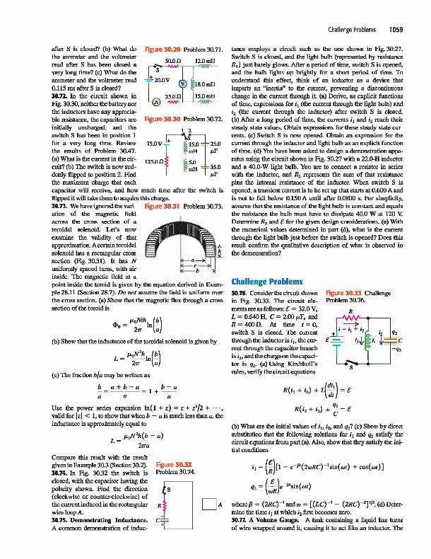
after S is closed? (b) What do the ammeter and the voltmeter read after S has been closed a very long time? (c) What do the ammeter and the voltmeter read 0.115 ms after S is closed? 30.n. In the circuit shown in Fig. 30.30, neither the battery nor the inductors have any appreciable resistance, the capacitors are initially uncharged, and the switch S has been in position I for a very long time. Review the results of Problem 30.47. (a) What is the current in the circuit? (b) The switch is now suddenly flipped to position 2. Fmd the maximum charge that each
Figure 30.29 Problem 30.71.
50.0.0 12.0mH
18.0mH
15.0mH
Figure 30.30 Problem 30.72.
75.0 V ,
125.0n ~
2
Cl 15.0
125.0
mH ",F
5.0 mH 35.0
",F
capacitor will receive, and how much time after the switch is flipped it will take them to acquire this charge. 30.13. We have ignored the vari- Figure 30.31 Problem 30.73. ation of the magnetic field across the cross section of a toroidal solenoid Let's now examine the validity of that approximation. A certain toroidal solenoid has a rectangular cross section (Fig. 30.31). It has N uniformly spaced torns, with air inside. The magnetic field at a point inside the toroid is given by the equation derived in Example 28.11 (Section 28.7). Do not assume the field is uniform over the cross section. (a) Show that the magnetic flux through a cross section of the toroid is
<l>B = /LoNiII,In(b} 2'IT a
(b) Show that the inductance of the toroidal solenoid is given by
L = iJ1JN'hIn(.~) 2'IT a
(c) The fraction b/a may be written as
b a+b-a b-a -=-- --= I +--a a a
Use the power series expansion In(1 + z) = Z + z'/2 + "', valid for Izl < I, to show that when b - a is much less than a, the inductance is approximately equal to
L = /LoN'h fj: - a) 2'ITa
Compare this result with the result given in Example 30.3 (Section 30.2). 30.74. In Fig. 30.32 the switch is closed, with the capacitor having the polarity shown. Find the direction (clockwise or counter-clockwise) of the current induced in the rectangular wire loop A. 30.75. Demonstrating Inductance. A common demonstration of induc-
F'lgure30.n Problem 30.74.
Challenge Problems 1059
tance employs a circuit such as the one shown in Fig. 30.27. Switch S is closed, and the light bulb (represented by resistance R,) just barely glows. After a period of time, switch S is opened, and the bulb lights up brightly for a short period of time. To understand this effect, think of an inductor as a device that imparts an "inertia" to the current, preventing a discontinuous change in the current through it. (a) Derive, as explicit functions of time, expressions for i, (the current through the light bulb) and i, (the current through the inductor) after switch S is closed. (b) After a long period of time, the currents i, and i, reach their steady-state values. Obtain expressions for these steady-state currents. (c) Switch S is now opened. Obtain an expression for the current through the inductor and light bulb as an explicit function of time. (d) You have been asked to design a demonstration apparatus using the circuit shown in Fig. 30.27 with a 22.0-H inductor and a 40.0-W light bulb. You are to connect a resistor in series with the inductor. and R, represents the sum of that resistance plus the internal resistance of the inductor. When switch S is opened. a transient current is to be set up that starts at 0.600 A and is not to fall below 0.150 A until after 0.0800 s. For simplicity. assume that the resistance of the light bulb is constant and equals the resistance the bulb must have to dissipate 40.0 W at 120 V. Determine R, and e for the given design considerations. (e) With the numerical values determined in part (d), what is the current through the light bulb just before the switch is opened? Does this result confirm the qualitative description of what is observed in the demonstration?
Challenge Problems 30.76. Considerthecircuit shown in Fig. 30.33. The circuit elements are as follows: e = 32.0 V, L = 0.640 H. C = 2.00/LF. and R = 400.0. At time t = 0, switch S is closed. The current through the inductor is i .. the current through the capacitor branch is ;,. and the charge on the capacitor is q,. (a) Using Kirchhoff's rules, verify the circuit equations
Figure 30.33 Challenge Problem 30.76.
R
R(i, + i,) + L(~:) = e
R(i, + i,) + ~ = e
(b) What are the initial values ofi .. i,. and q,? (c) Show by direct substitution that the following solutions for i, and q, satisfy the circuit equations from part (a). Also, show that they satisfy the initial conditions
i, = (!)[I - e-P'(2wRC)-'sin(wt) + cos(wt)]
q, = (!Rk"'Sin(wt)
whereJ3 = (2RC)-' andw = [(LC)-' - (2RC)-'],f2. (d) Determine the time t, at which i, first becomes zero. 30.77. A Volume Gauge. A tank containing a liquid has torns of wire wrapped around it, causing it to act like an inductor. The
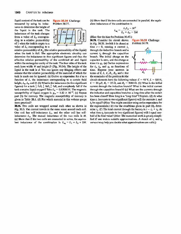
1060 CHAPTER 30 Inductance
liquid content of the tank can be Figure 30.34 Challenge measured by using its induc- Problem 30.77. tance tu determine the height of the liquid in the tank. The inductance of the tank changes from a value of Lo corresponding tu a relative permeability of 1 when the tank is empty tu a value of L, corresponding tu a
Df . . I·p. [gAir .u~ 11 _ ~.~ ~W-
relative permeability of Km (the relative permeability of the liquid) when the tank is full. The appropriate electrouic circuitty can determine the inductance tu five significant figures and thus the effective relative penneability of the combined air and liquid within the rectangular cavity of the tank. The four sides of the tank each have width W and height D (Fig. 30.34). The height of the liquid in the tank is d. You can ignore any fringing effects and assume that the relative permeability of the material of which the tank is made can be ignored. (a) Derive an expression for d as a function of L, the inductance corresponding tu a certain fluid height, Lo, L" and D. (b) What is the inductance (tu five significant figures) for a tank 1 full, ! full, ~ full, and completely full if the tank contains liquid oxygen? Take Lo = 0.63000 H. The magnetic susceptibility of liquid oxygen is Xm = 1.52 X 10⁻³
• (c) Repeat part (b) for mercury. The magnetic susceptibility of mercury is given in Table 28.1. (d) For which material is this volume gauge more practical? 30.78. Two coils are wrapped around each other as shown in Fig. 30.3. The current travels in the same sense around each coil. One coil has self-inductance L.. and the other coil has selfinductance L2• The mutual inductance of the two coils is M. (a) Show that if the two coils are connected in series, the equivalent inductance of the combination is L .. = LI + L,. + 2M.
(b) Show that if the two coils are connected in parallel, the equivalent inductance of the combination is
L =~L2-=-~ .. L I +L2 -2M
(Hint: See the hint for Problem 30.47.) 30.79. Consider the circuit shown Figure 30.35 Challenge in Fig. 30.35. Switch S is closed at Problem 30.79. time t = 0, causing a current i 1
through the inductive branch and a current i2 through the capacitive branch. The initial charge on the capacitur is zero, and the charge at time t is q2. (a) Derive expressions for i.. i2, and q2 as functions of time. Express your answers in terms of C, L, C, R I , R2, and t. For c the remainder of the problem let the circuit elements have the following values: C = 48 V, L = 8.0 H, C = 20 p,F, RI = 25.n, and R2 = 5000.n. (b) What is the initial current through the inductive branch? What is the initial current through the capacitive branch? (c) What are the currents through the inductive and capacitive branches a long time after the switch has been closed? How long is a "long time"? Explain. (d) At what time tl (accurate tu two significant figures) will the currents i l and i2 be equal? (Hint: You might consider using series expansions for the exponentials.) (e) For the conditions given in part (d), determine i l • (f) The tutal current through the battety is i = i l + ;2. At what time t2 (accurate tu two significant figures) will i equal onehalf of its final value? (Hint: The numerical work is greatly simplified if one makes suitable approxin1ations. A sketch of i l and i2 versus t may help you decide what approximations are valid.)