channel pair to pair resistance unbalance-use case … pairs of conductors used for power delivery....
TRANSCRIPT
Power Matters
IEEE802.3 4P Task Force
Channel Pair To Pair Resistance Unbalance (CP2PRUNB)(only cables and connectors)
Analysis of ad-hoc proposed use casesRev 004c
July 2014
Yair Darshan Microsemi

IEEE802.3bt, Channel P2P RUNB - Analysis of ad-hoc proposed use cases, Rev 004c, Yair Darshan July 2014,
Chris Diminico
Larsen, Wayne / Commscope
Leonard Stencel / Bourns
David Tremblay / HP
Fred Schindler / Seen Simply
Lennart Yseboodt / Philips
Christian Beia / ST
Matthias Wendt / Philips
George Zimmerman/ CME Consulting, Affiliations: Commscope & Aquantia
Jean Picard / TI
Kousalya Balasubramanian / Cisco
Pavlick Rimboim / MSCC
Brian Buckmeier / BEL
Sesha Panguluri / Broadcom
Supporters
2
IEEE802.3bt, Channel P2P RUNB - Analysis of ad-hoc proposed use cases, Rev 004c, Yair Darshan July 2014,
To close the TBDs (P2PRUNB and Resistance Difference) from base line text motion from May 2014 meeting.
To verify that during Channel P2PRUNB compliance tests we can pass the above requirements with realistic use cases while what is considered not typical or realistic use cases are covered too by the above requirements in a clear way and not subject to confusion or false interpretation.
Objectives
3
IEEE802.3bt, Channel P2P RUNB - Analysis of ad-hoc proposed use cases, Rev 004c, Yair Darshan July 2014,
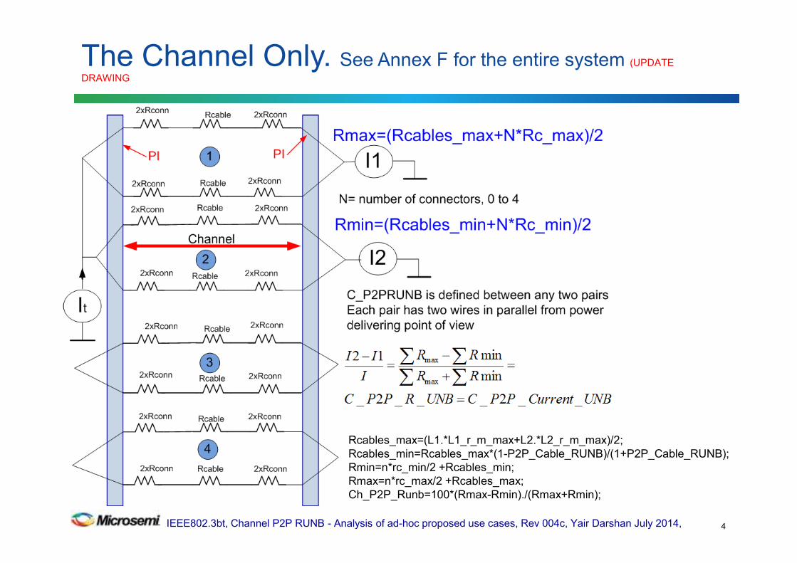
The Channel Only. See Annex F for the entire system (UPDATE
DRAWING
4
Rcables_max=(L1.*L1_r_m_max+L2.*L2_r_m_max)/2;
Rcables_min=Rcables_max*(1-P2P_Cable_RUNB)/(1+P2P_Cable_RUNB);
Rmin=n*rc_min/2 +Rcables_min;
Rmax=n*rc_max/2 +Rcables_max;
Ch_P2P_Runb=100*(Rmax-Rmin)./(Rmax+Rmin);
IEEE802.3bt, Channel P2P RUNB - Analysis of ad-hoc proposed use cases, Rev 004c, Yair Darshan July 2014,
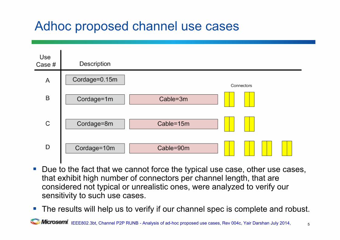
Due to the fact that we cannot force the typical use case, other use cases, that exhibit high number of connectors per channel length, that are considered not typical or unrealistic ones, were analyzed to verify our sensitivity to such use cases.
The results will help us to verify if our channel spec is complete and robust. .
Adhoc proposed channel use cases
5
IEEE802.3bt, Channel P2P RUNB - Analysis of ad-hoc proposed use cases, Rev 004c, Yair Darshan July 2014,
Channel P2P RUNB-Addressing TBDs
6
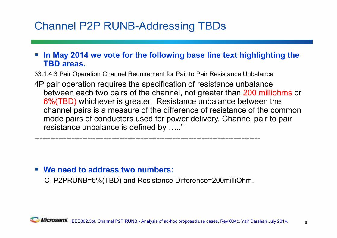
In May 2014 we vote for the following base line text highlighting the TBD areas.
33.1.4.3 Pair Operation Channel Requirement for Pair to Pair Resistance Unbalance
4P pair operation requires the specification of resistance unbalance between each two pairs of the channel, not greater than 200 milliohms or 6%(TBD) whichever is greater. Resistance unbalance between the channel pairs is a measure of the difference of resistance of the common mode pairs of conductors used for power delivery. Channel pair to pair resistance unbalance is defined by J..”
-------------------------------------------------------------------------------------
We need to address two numbers:
C_P2PRUNB=6%(TBD) and Resistance Difference=200milliOhm.
IEEE802.3bt, Channel P2P RUNB - Analysis of ad-hoc proposed use cases, Rev 004c, Yair Darshan July 2014,
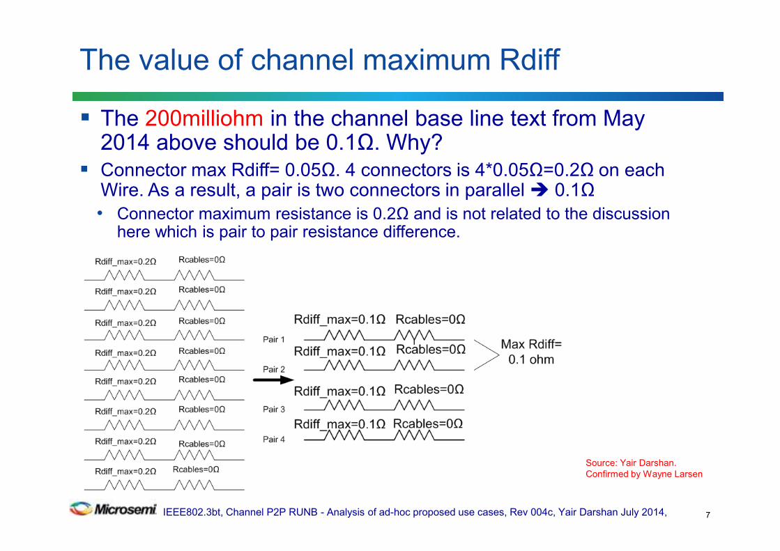
The 200milliohm in the channel base line text from May 2014 above should be 0.1Ω. Why?
Connector max Rdiff= 0.05Ω. 4 connectors is 4*0.05Ω=0.2Ω on each Wire. As a result, a pair is two connectors in parallel 0.1Ω
• Connector maximum resistance is 0.2Ω and is not related to the discussion here which is pair to pair resistance difference.
The value of channel maximum Rdiff
7
Source: Yair Darshan.
Confirmed by Wayne Larsen

IEEE802.3bt, Channel P2P RUNB - Analysis of ad-hoc proposed use cases, Rev 004c, Yair Darshan July 2014,
Presentation Flow
8
Step Analyzing the proposed use cases
1 a) Compare analysis results of proposed use case A,B,C and D to 6%
b) Checking other use cases near the proposed use cases to check the
Channel P2PRUNB sensitivity from deviation from the proposed use cases.
2 Understanding the reasons and rationale behind the results from different
angle and as function of channel parameters
3 Checking if P2PRUNB and Rdiff is sufficient to specify the channel for any
use case.
4 Checking if Rdiff alone is sufficient to define the channel
5 Conclusions and information obtained from this work regarding:
-Channel
-Future work on PSE and PD PI.
IEEE802.3bt, Channel P2P RUNB - Analysis of ad-hoc proposed use cases, Rev 004c, Yair Darshan July 2014,
Channel Component Data used in this work
9
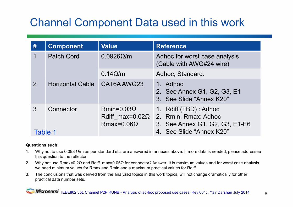
# Component Value Reference
1 Patch Cord 0.0926Ω/m Adhoc for worst case analysis
(Cable with AWG#24 wire)
0.14Ω/m Adhoc, Standard.
2 Horizontal Cable CAT6A AWG23 1. Adhoc
2. See Annex G1, G2, G3, E1
3. See Slide “Annex K20”
3 Connector Rmin=0.03Ω
Rdiff_max=0.02Ω
Rmax=0.06Ω
1. Rdiff (TBD) : Adhoc
2. Rmin, Rmax: Adhoc
3. See Annex G1, G2, G3, E1-E6
4. See Slide “Annex K20”
Questions such:
1. Why not to use 0.098 Ω/m as per standard etc. are answered in annexes above. If more data is needed, please addressee
this question to the reflector.
2. Why not use Rmax=0.2Ω and Rdiff_max=0.05Ω for connector? Answer: It is maximum values and for worst case analysis
we need minimum values for Rmax and Rmin and a maximum practical values for Rdiff.
3. The conclusions that was derived from the analyzed topics in this work topics, will not change dramatically for other
practical data number sets.
Table 1

IEEE802.3bt, Channel P2P RUNB - Analysis of ad-hoc proposed use cases, Rev 004c, Yair Darshan July 2014,
From previous ad-hoc meetings decisions: To check use cases A, B, C and D per the table below for Channel P2PRUNB specification derivation.
Additional use cases were added (total 16 at a time) after running the simulations in order to find Channel P2PRUN hidden peaks for specification sensitivity analysis.
Table below provides a summary. See details next slides.
Use cases to be checked during analysis
10
Use
case
Connectors Cordage[m] Cable[m] Max. Channel P2PRUN
A 0 ≥0.15 0 5% (equal to Cable P2PRUNB)
0 0 ≥0.15
B 2 1 3 9.2% (Covered by the Rdiff requirement)
C 4 8 15 6.47%
D 4 10 90 5.45%
2-4,
6-8
10
1
2
4
See curve next slide.
Considered as
unrealistic use cases
10% - 20% (Covered by the Rdiff requirement)

IEEE802.3bt, Channel P2P RUNB - Analysis of ad-hoc proposed use cases, Rev 004c, Yair Darshan July 2014,
Use case analysis results and proposed objective
11
• A,B,C and D are considered as Typical use cases. The other
use cases are used for discovering peaks that should be
covered by the specification as well (the Rdiff=0.1Ω max.)
• Use case B is above 7% however it is
covered by the Rdiff. See next slides.
• Use Case C is above 6%. Change to 7%.
A
B
CD
Since we can not force only realistic use cases, the question is how we ensure that channel
will not fail P2PRUNB compliance tests when tested with different use cases than A,B,C and D?

IEEE802.3bt, Channel P2P RUNB - Analysis of ad-hoc proposed use cases, Rev 004c, Yair Darshan July 2014,
Channel P2PRUNB vs. Use case parameters
12
A B C D
When cable resistance starts to dominate over the
connectors, Channel P2PRUNB decreases.
IEEE802.3bt, Channel P2P RUNB - Analysis of ad-hoc proposed use cases, Rev 004c, Yair Darshan July 2014,
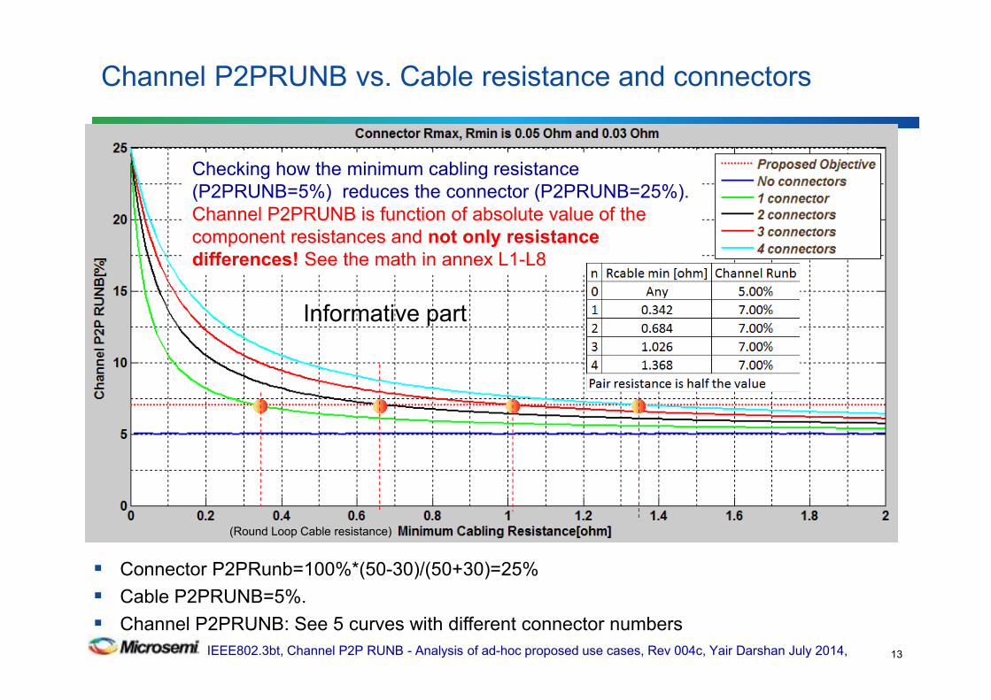
Connector P2PRunb=100%*(50-30)/(50+30)=25%
Cable P2PRUNB=5%.
Channel P2PRUNB: See 5 curves with different connector numbers
Channel P2PRUNB vs. Cable resistance and connectors
13
Checking how the minimum cabling resistance
(P2PRUNB=5%) reduces the connector (P2PRUNB=25%).
Channel P2PRUNB is function of absolute value of the
component resistances and not only resistance
differences! See the math in annex L1-L8
Informative part
(Round Loop Cable resistance)
IEEE802.3bt, Channel P2P RUNB - Analysis of ad-hoc proposed use cases, Rev 004c, Yair Darshan July 2014,
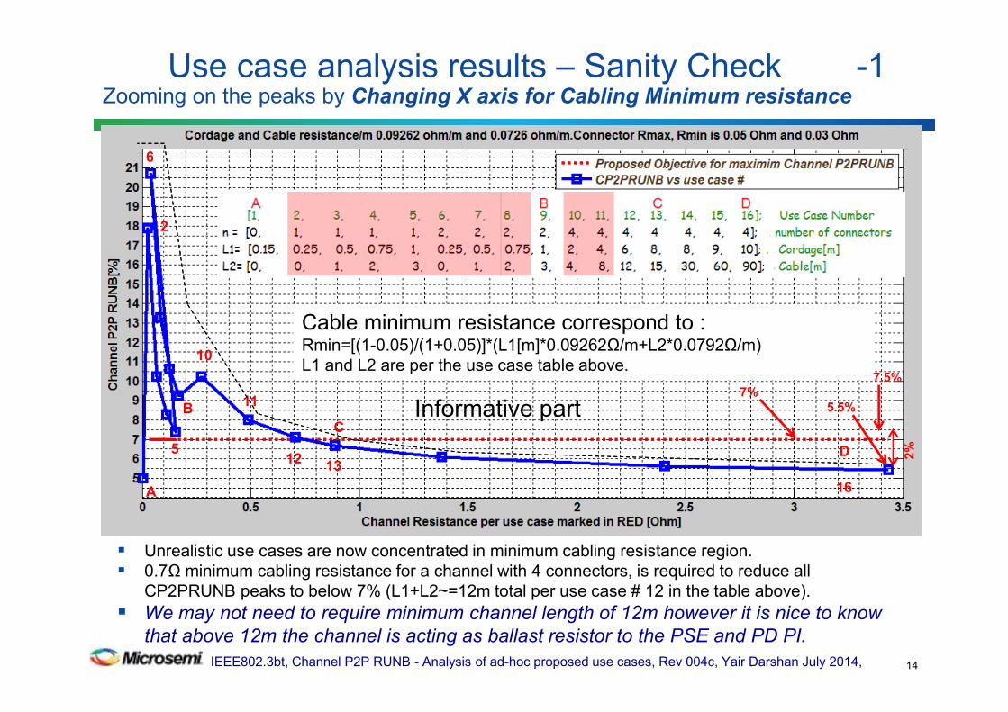
Unrealistic use cases are now concentrated in minimum cabling resistance region.
0.7Ω minimum cabling resistance for a channel with 4 connectors, is required to reduce all
CP2PRUNB peaks to below 7% (L1+L2~=12m total per use case # 12 in the table above).
We may not need to require minimum channel length of 12m however it is nice to know
that above 12m the channel is acting as ballast resistor to the PSE and PD PI.
Use case analysis results – Sanity Check -1 Zooming on the peaks by Changing X axis for Cabling Minimum resistance
14
2
A
6
B
C
D
10
5
Cable minimum resistance correspond to :Rmin=[(1-0.05)/(1+0.05)]*(L1[m]*0.09262Ω/m+L2*0.0792Ω/m)
L1 and L2 are per the use case table above.
1312
16
11 Informative part
2%
7%7.5%
5.5%
IEEE802.3bt, Channel P2P RUNB - Analysis of ad-hoc proposed use cases, Rev 004c, Yair Darshan July 2014,
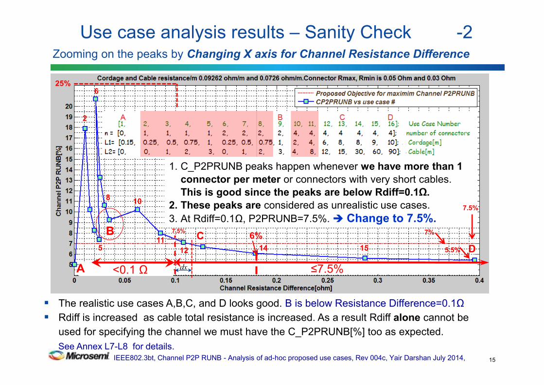
The realistic use cases A,B,C, and D looks good. B is below Resistance Difference=0.1Ω
Rdiff is increased as cable total resistance is increased. As a result Rdiff alone cannot be
used for specifying the channel we must have the C_P2PRUNB[%] too as expected.
See Annex L7-L8 for details.
Use case analysis results – Sanity Check -2 Zooming on the peaks by Changing X axis for Channel Resistance Difference
15
1. C_P2PRUNB peaks happen whenever we have more than 1
connector per meter or connectors with very short cables.
This is good since the peaks are below Rdiff=0.1Ω.
2. These peaks are considered as unrealistic use cases.
3. At Rdiff=0.1Ω, P2PRUNB=7.5%. Change to 7.5%.
2
6
B C
D
10
5 12
11
<0.1 Ω < 7%
8
≤7.5% <0.1 ΩA
6%
1514
dx
7.5%
25%
7%
7.5%
5.5%
IEEE802.3bt, Channel P2P RUNB - Analysis of ad-hoc proposed use cases, Rev 004c, Yair Darshan July 2014,
We can see that the high C_P2PRUNB peaks happen when:
• There are more than 1 connector per 1m of cabling (ratio of 0.22 to 0.25) and/or:
• The cables and patch cords are short and exhibit low resistance compared to total connector resistance
• The above use cases are considered "unrealistic" ones, covered by Rdiff=0.1Ω (was 0.2 Ω).
Use Case B is considered to be realistic, and exceeds the initial proposed 7% but it is covered by Rdiff=0.1Ω (was 0.2 Ω) requirement.
– It has 2 connectors over 4m channel which is 2/4=0.5 ratio which is way different that the general behavior above of 0.25 ratio. So all is good
We saw that:
• Per the Rdiff curve: we can select the specification numbers between:
• (a) Rdiff=0.1Ω, P2PRUNB=7.5%. (b) Rdiff=0.117Ω, P2PRUNB=7%. (c) Rdiff=0.1Ω, P2PRUNB=7%.
• Option (a) is the correct one from worst case analysis point of view.
• Option (b) is not matching the maximum P2P Rdiff per connector standards =0.1 Ω
• Option (c) is possible if counting on the fact that it is worst case analysis and we have design margins for small deviation of 0.5%/0.025Ω. which may be the best optimized cost effective set of parameters.
We may need informative section that says that for 4P operation, it is recommended to use a channel that has ≤1 connector per meter (maximum 4 connectors per standard). Anyway, unrealistic use cases are covered by Rdiff part in the spec.
Conclusions regarding Channel Unbalance Requirements -1
16
IEEE802.3bt, Channel P2P RUNB - Analysis of ad-hoc proposed use cases, Rev 004c, Yair Darshan July 2014,
4P operation with minimum cable resistance help us:
(a) It will reduce some of the burden on PD PI and PSE PI
(b) It helps to reduce overall End to End Channel P2P RUNB and as a
result will reduce the maximum current over the pair with lowest
end to end resistance.
– The implication of the above is equivalent to minimum cable length.
This work shows clearly (by analytical proof and simulations) the following facts:
Only Resistance Difference Requirement for Channel specifications (Rdiff=|Rmax-Rmin|)
is mathematically and practically insufficient. See L1 –L8 for analytical derivation. This
requirement leads to clear interoperability issues. See L7 and L8. In channel, in particular, it
will contradict cable 5% P2PRUNB maximum limit. So we need at least both Rdiff and
P2PRUNB parameters for the channel as we have already in the base line text. Moreover
inexplicitly, for channel Rdif≤0.1Ω , P2PRUNB is bounded by the connector P2PRUNB
(25% per the data used in this work).
Conclusions regarding Channel Unbalance Requirements -2
17
IEEE802.3bt, Channel P2P RUNB - Analysis of ad-hoc proposed use cases, Rev 004c, Yair Darshan July 2014,
The proposed unbalanced parameter values for the base line text are:
• Channel P2PRUNB max.: 7.5% (option a) or 7% (option c)
• Resistance Difference max: 0.1Ω
– (P2PRUNB for Rdiff≤ 0.1Ω is bounded by Connectors actual Rmin, Rmax values i.e.
25% in our analysis. Theoretically it can be higher and it will be bounded by system
unbalanced parameters)
Adhoc use cases proposals covers:
• Realistic use cases with short cables and long cables
• "unrealistic" use cases with short and long cables as well that we
actually cannot control or limit their use.
• It is worst case analysis, therefore contain inherent margins
• It is complete.
Summary
18
IEEE802.3bt, Channel P2P RUNB - Analysis of ad-hoc proposed use cases, Rev 004c, Yair Darshan July 2014,
Specify Channel Unbalance parameters to:
C_P2PRUNB=7.5% max.
Channel Resistance Difference=0.1Ω max.
Which ever is greater.
Notes:
1. 7% is the cost effective choice per the conclusions slides.
2. 7.5% is the accurate solution.
Group to discuss.
Proposed update to Channel base line text
19

IEEE802.3bt, Channel P2P RUNB - Analysis of ad-hoc proposed use cases, Rev 004c, Yair Darshan July 2014,
Q&A
20
IEEE802.3bt, Channel P2P RUNB - Analysis of ad-hoc proposed use cases, Rev 004c, Yair Darshan July 2014,
Backup slides
21

IEEE802.3bt, Channel P2P RUNB - Analysis of ad-hoc proposed use cases, Rev 004c, Yair Darshan July 2014,
The following is the subject for future work:
In TIA/EIA/ISO/IEEE specifications, for pair Runb (wire to wire within a pair), only Runb and Rdiff was specified. For P2P definition especially for short channels, it will be advantageously specifying:
- P2PRUNB≤25%(TBD) for Rdiff ≤0.1Ω or alternatively:
- specifying Rmin for the channel with Rdiff ≤0.1Ω. See Annex L1-L8, P, P1.
This will put upper bound for P2PRUNB at Rdiff ≤0.1Ω region.
Proposed Next steps for the PSE and PD PI models - 1
22

IEEE802.3bt, Channel P2P RUNB - Analysis of ad-hoc proposed use cases, Rev 004c, Yair Darshan July 2014,
PSE PI unbalance parameters
PSE PI unbalance parameters shall include:
• P2PRUNB[%]
• Voltage Difference.
For complete spec, check if adding Rmin is needed or we can satisfied with only the above 2. See Annex L1 –L6 for our options.
PD PI unbalance parameters
• P2PRUNB[%]
• Voltage Difference.
For complete spec, check if adding Rmin is needed or we can satisfied with only the above 2. See Annex L1 –L6 for our options.
Proposed Next steps for the PSE and PD PI models - 2
23

IEEE802.3bt, Channel P2P RUNB - Analysis of ad-hoc proposed use cases, Rev 004c, Yair Darshan July 2014,
With 7.5% C_P2PRUNB limits.
Use case analysis results – Sanity Check Zooming on the peaks by Changing X axis for Channel Resistance Difference
24
1. C_P2PRUNB peaks happen whenever we have more than 1
connector per meter or connectors with very short cables. This
is good since the peaks are below Rdiff=0.1Ω.
2. These peaks are considered as unrealistic use cases.
3. At Rdiff=0.1Ω, P2PRUNB=7.5%. Change to 7.5%.
2
6
B C
D
10
5 12
11
8
≤7.5% <0.1 ΩA
1514
25%
IEEE802.3bt, Channel P2P RUNB - Analysis of ad-hoc proposed use cases, Rev 004c, Yair Darshan July 2014,
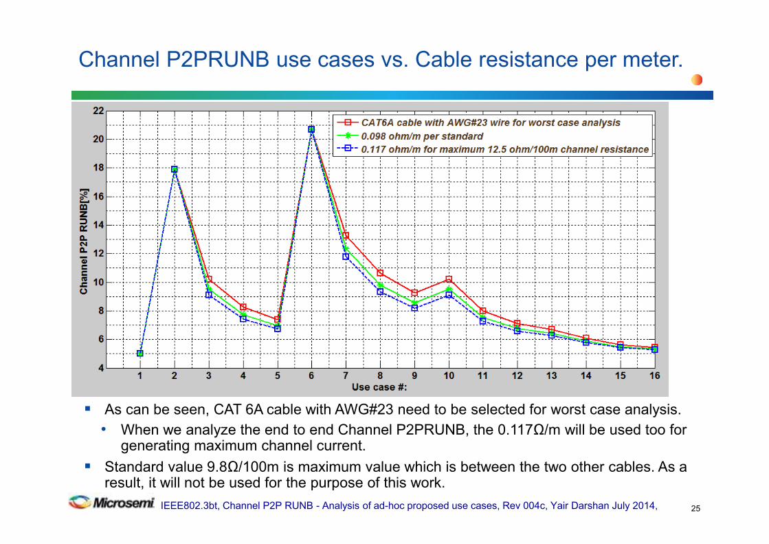
As can be seen, CAT 6A cable with AWG#23 need to be selected for worst case analysis.
• When we analyze the end to end Channel P2PRUNB, the 0.117Ω/m will be used too for generating maximum channel current.
Standard value 9.8Ω/100m is maximum value which is between the two other cables. As a result, it will not be used for the purpose of this work.
Channel P2PRUNB use cases vs. Cable resistance per meter.
25

IEEE802.3bt, Channel P2P RUNB - Analysis of ad-hoc proposed use cases, Rev 004c, Yair Darshan July 2014,
Lower peaks received with using connector Rdiff=0.015Ω instead of 0.02 Ω compared to previous run.
Use case analysis results with connector Rdiff=0.015Ω instead 0.02 Ω.
26
7% example

IEEE802.3bt, Channel P2P RUNB - Analysis of ad-hoc proposed use cases, Rev 004c, Yair Darshan July 2014,
This use case is unlikely to happen although it represent connector Rmax and Rdiff maximum values per standard while we are looking for minimum values for worst case analysis.
Peaks are lower than Rmax=0.05Ω and Rdiff=0.02Ω .
See more effective view when It will require higher Rdiff e.g. 0.2 instead of 0.1 to cover all use cases including use case B which is considered to be realistic one.
Use case analysis results with connector Rmax=0.2Ω Rdiff=0.05Ω -1
27
7.5% example
IEEE802.3bt, Channel P2P RUNB - Analysis of ad-hoc proposed use cases, Rev 004c, Yair Darshan July 2014,
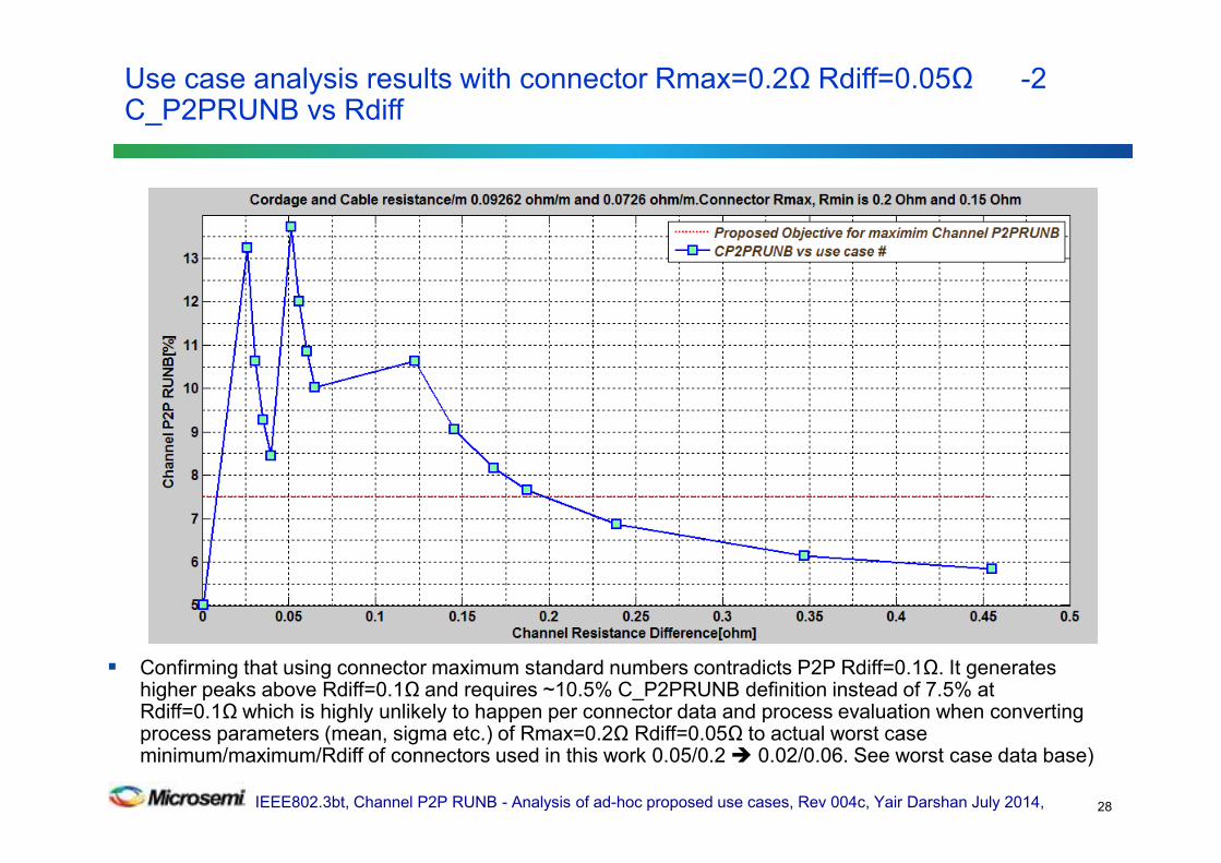
Confirming that using connector maximum standard numbers contradicts P2P Rdiff=0.1Ω. It generates higher peaks above Rdiff=0.1Ω and requires ~10.5% C_P2PRUNB definition instead of 7.5% at Rdiff=0.1Ω which is highly unlikely to happen per connector data and process evaluation when converting process parameters (mean, sigma etc.) of Rmax=0.2Ω Rdiff=0.05Ω to actual worst case minimum/maximum/Rdiff of connectors used in this work 0.05/0.2 0.02/0.06. See worst case data base)
Use case analysis results with connector Rmax=0.2Ω Rdiff=0.05Ω -2C_P2PRUNB vs Rdiff
28

IEEE802.3bt, Channel P2P RUNB - Analysis of ad-hoc proposed use cases, Rev 004c, Yair Darshan July 2014,
With 7.5% C_P2PRUNB limits.
Channel P2PRUNB vs. Cable resistance and connectors
29
IEEE802.3bt, Channel P2P RUNB - Analysis of ad-hoc proposed use cases, Rev 004c, Yair Darshan July 2014,
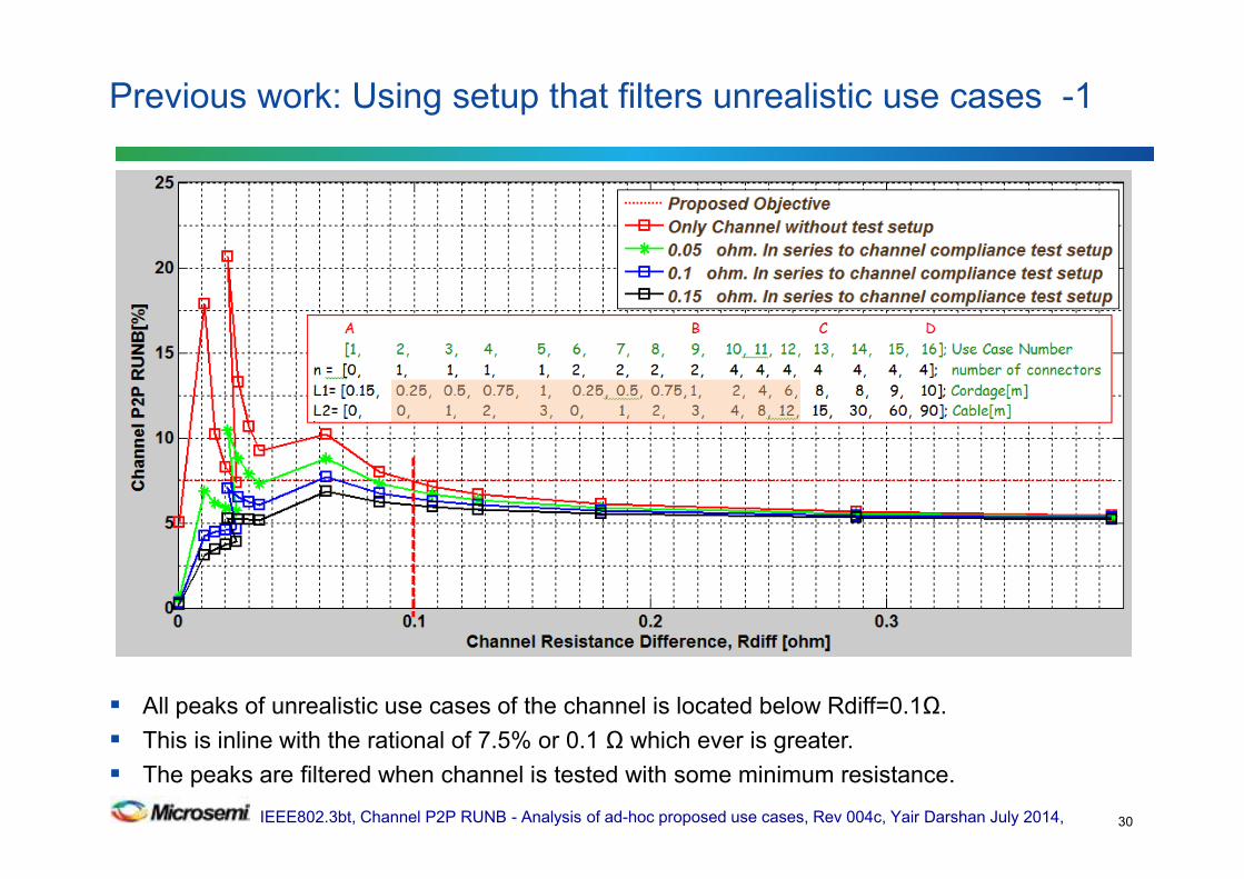
All peaks of unrealistic use cases of the channel is located below Rdiff=0.1Ω.
This is inline with the rational of 7.5% or 0.1 Ω which ever is greater.
The peaks are filtered when channel is tested with some minimum resistance.
Previous work: Using setup that filters unrealistic use cases -1
30
IEEE802.3bt, Channel P2P RUNB - Analysis of ad-hoc proposed use cases, Rev 004c, Yair Darshan July 2014,
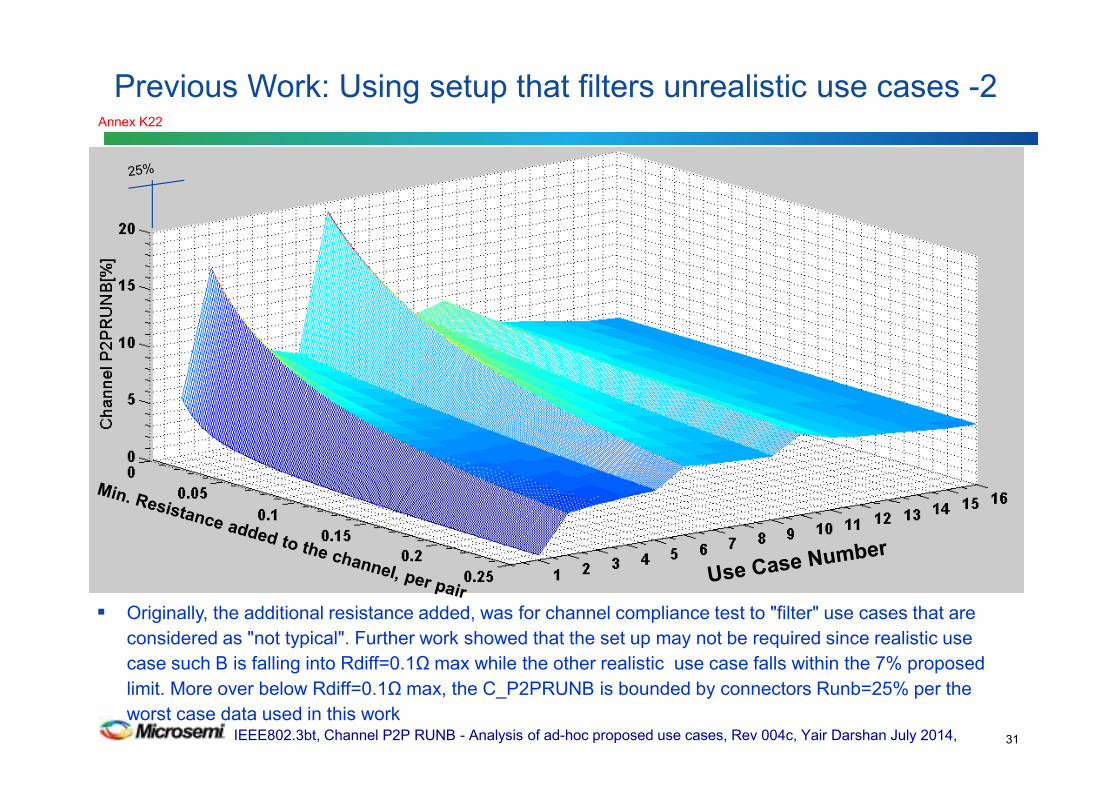
Originally, the additional resistance added, was for channel compliance test to "filter" use cases that are
considered as "not typical". Further work showed that the set up may not be required since realistic use
case such B is falling into Rdiff=0.1Ω max while the other realistic use case falls within the 7% proposed
limit. More over below Rdiff=0.1Ω max, the C_P2PRUNB is bounded by connectors Runb=25% per the
worst case data used in this work
Previous Work: Using setup that filters unrealistic use cases -2
31
Annex K22
IEEE802.3bt, Channel P2P RUNB - Analysis of ad-hoc proposed use cases, Rev 004c, Yair Darshan July 2014,
Previous Work: Using setup that filters unrealistic use cases -3
32
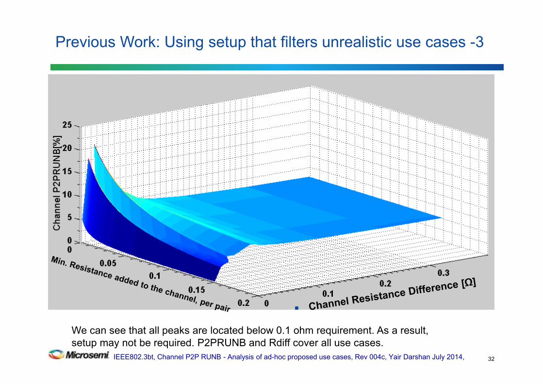
We can see that all peaks are located below 0.1 ohm requirement. As a result,
setup may not be required. P2PRUNB and Rdiff cover all use cases.
IEEE802.3bt, Channel P2P RUNB - Analysis of ad-hoc proposed use cases, Rev 004c, Yair Darshan July 2014,
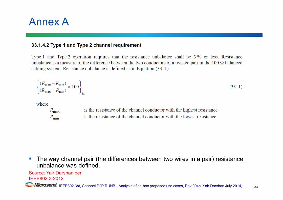
The way channel pair (the differences between two wires in a pair) resistance unbalance was defined.
Annex A
33
Source: Yair Darshan per
IEEE802.3-2012

IEEE802.3bt, Channel P2P RUNB - Analysis of ad-hoc proposed use cases, Rev 004c, Yair Darshan July 2014,
Resistance unbalance of a channel
Annex A2 - ANSI/TIA-568-C.2
34
Source: Yair Darshan per
ANSI/TIA-568-C.2
IEEE802.3bt, Channel P2P RUNB - Analysis of ad-hoc proposed use cases, Rev 004c, Yair Darshan July 2014,
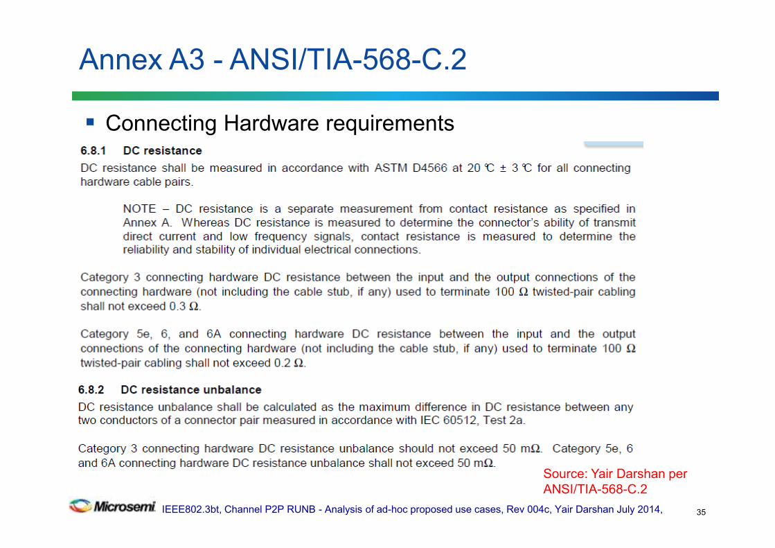
Connecting Hardware requirements
Annex A3 - ANSI/TIA-568-C.2
35
Source: Yair Darshan per
ANSI/TIA-568-C.2
IEEE802.3bt, Channel P2P RUNB - Analysis of ad-hoc proposed use cases, Rev 004c, Yair Darshan July 2014,
The fact is that the cabling channel models assumes some distance between the near end and the far end connecting hardware. As an example in 4 connector channel, the NEXT limits are based on two near end connectors and the far end connectors are not included.
Look at the equation of the NEXT for the channel.
For Return Loss worst case channels are developed based on models with assumed distances between connecting hardware.
More inputs will be updated per Chris DiMinico contribution.
Annex A4: What is the minimum channel length per TIA/ISO standards
36
IEEE802.3bt, Channel P2P RUNB - Analysis of ad-hoc proposed use cases, Rev 004c, Yair Darshan July 2014,
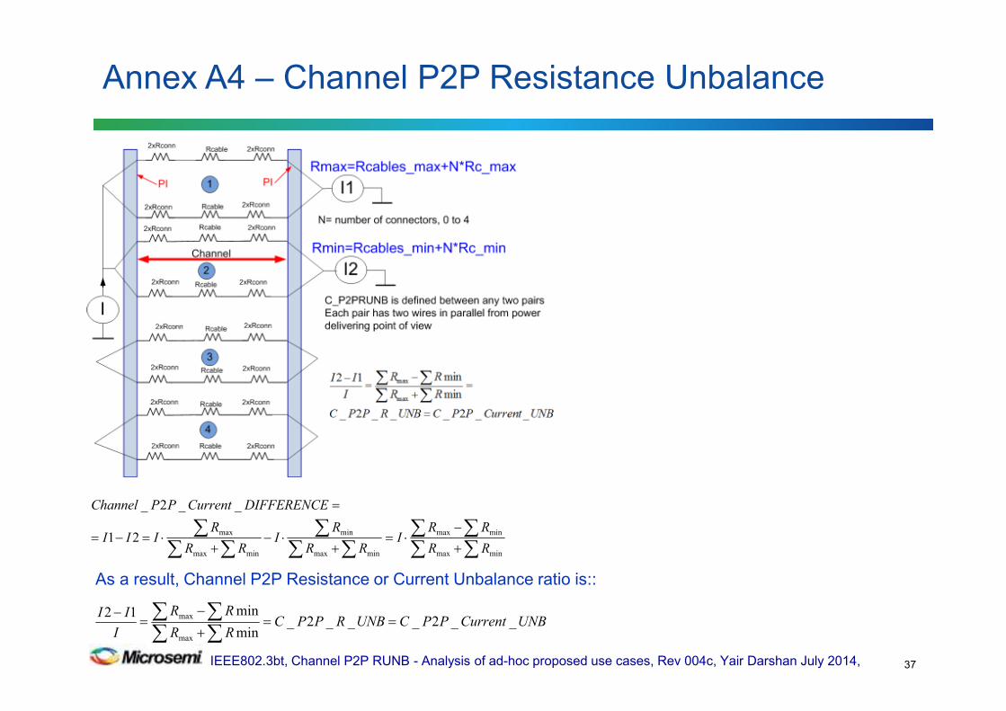
Annex A4 – Channel P2P Resistance Unbalance
37
∑∑∑∑
∑∑∑
∑∑∑
+
−⋅=
+⋅−
+⋅=−=
=
minmax
minmax
minmax
min
minmax
max21
__2_
RR
RRI
RR
RI
RR
RIII
DIFFERENCECurrentPPChannel
UNBCurrentPPCUNBRPPCRR
RR
I
II__2___2_
min
min12
max
max ==+
−=
−
∑∑∑∑
As a result, Channel P2P Resistance or Current Unbalance ratio is::
IEEE802.3bt, Channel P2P RUNB - Analysis of ad-hoc proposed use cases, Rev 004c, Yair Darshan July 2014,
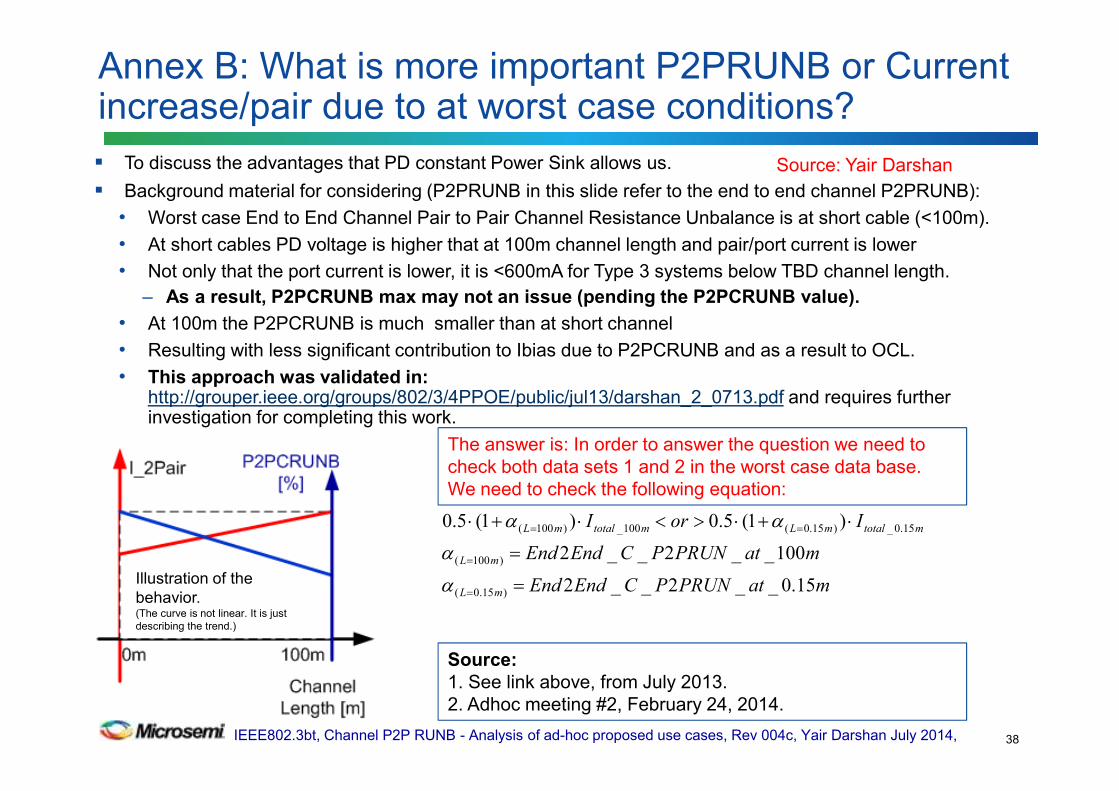
To discuss the advantages that PD constant Power Sink allows us.
Background material for considering (P2PRUNB in this slide refer to the end to end channel P2PRUNB):
• Worst case End to End Channel Pair to Pair Channel Resistance Unbalance is at short cable (<100m).
• At short cables PD voltage is higher that at 100m channel length and pair/port current is lower
• Not only that the port current is lower, it is <600mA for Type 3 systems below TBD channel length.
– As a result, P2PCRUNB max may not an issue (pending the P2PCRUNB value).
• At 100m the P2PCRUNB is much smaller than at short channel
• Resulting with less significant contribution to Ibias due to P2PCRUNB and as a result to OCL.
• This approach was validated in: http://grouper.ieee.org/groups/802/3/4PPOE/public/jul13/darshan_2_0713.pdf and requires further investigation for completing this work.
Annex B: What is more important P2PRUNB or Current increase/pair due to at worst case conditions?
38
Illustration of the
behavior.(The curve is not linear. It is just
describing the trend.)
Source:
1. See link above, from July 2013.
2. Adhoc meeting #2, February 24, 2014.
The answer is: In order to answer the question we need to
check both data sets 1 and 2 in the worst case data base.
We need to check the following equation:
Source: Yair Darshan
matPRUNPCEndEnd
matPRUNPCEndEnd
IorI
mL
mL
mtotalmLmtotalmL
15.0__2__2
100__2__2
)1(5.0)1(5.0
)15.0(
)100(
15.0_)15.0(100_)100(
=
=
⋅+⋅><⋅+⋅
=
=
==
α
α
αα
IEEE802.3bt, Channel P2P RUNB - Analysis of ad-hoc proposed use cases, Rev 004c, Yair Darshan July 2014,
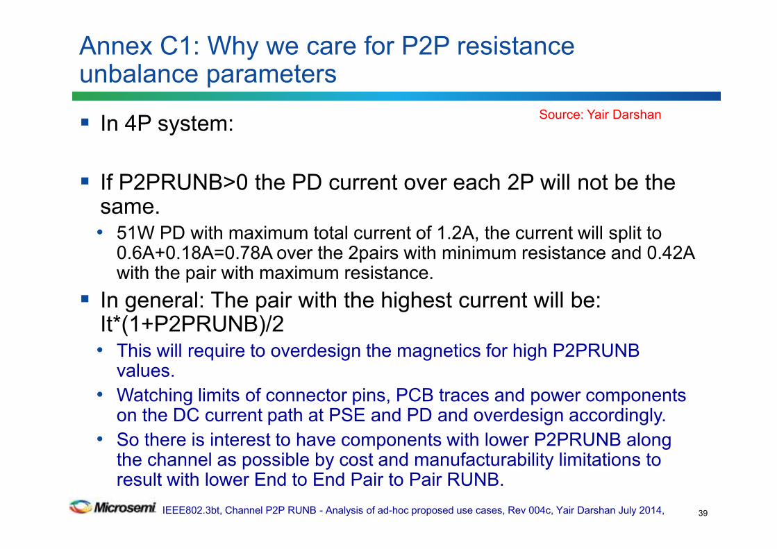
In 4P system:
If P2PRUNB>0 the PD current over each 2P will not be the same.• 51W PD with maximum total current of 1.2A, the current will split to
0.6A+0.18A=0.78A over the 2pairs with minimum resistance and 0.42A with the pair with maximum resistance.
In general: The pair with the highest current will be: It*(1+P2PRUNB)/2• This will require to overdesign the magnetics for high P2PRUNB
values.
• Watching limits of connector pins, PCB traces and power components on the DC current path at PSE and PD and overdesign accordingly.
• So there is interest to have components with lower P2PRUNB along the channel as possible by cost and manufacturability limitations to result with lower End to End Pair to Pair RUNB.
Annex C1: Why we care for P2P resistance unbalance parameters
39
Source: Yair Darshan

IEEE802.3bt, Channel P2P RUNB - Analysis of ad-hoc proposed use cases, Rev 004c, Yair Darshan July 2014,
Other concerns was how it will affect on PD minimum available power for a 60W system (two times the 802.3at power). The decision was that for our current data base we can supply 49W for the PD (instead of 51W). See 802.3bt objective.• This was done by calculating what will be the power at the PD if we
keep maximum 600mA at the pair in order not to cause issues to Type 2 component/ devices that can work with 4P
Other concern was if P2PRUNB will increase power loss on the cable. We show that now it will not. Moreover we show that if P2PRUNB increased, the power loss is decreased.
See: http://www.ieee802.org/3/4PPOE/public/nov13/darshan_02_1113.pdf for more details.
Annex C2: Why we care for P2P resistance unbalance parameters
40
]21[5.0 max_
2 PCRUNBPRItNTrise Nloop −⋅⋅⋅⋅= θ
Source: Yair Darshan
IEEE802.3bt, Channel P2P RUNB - Analysis of ad-hoc proposed use cases, Rev 004c, Yair Darshan July 2014,
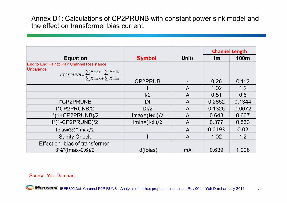
Equation Symbol Units
Channel Length
1m 100mEnd to End Pair to Pair Channel Resistance
Unbalance:
CP2PRUB - 0.26 0.112
I A 1.02 1.2
I/2 A 0.51 0.6
I*CP2PRUNB DI A 0.2652 0.1344
I*CP2PRUNB/2 DI/2 A 0.1326 0.0672
I*(1+CP2PRUNB)/2 Imax=(I+di)/2 A 0.643 0.667
I*(1-CP2PRUNB)/2 Imin=(I-di)/2 A 0.377 0.533
Ibias=3%*Imax/2 A 0.0193 0.02
Sanity Check I A 1.02 1.2
Effect on Ibias of transformer:
3%*(Imax-0.6)/2 d(Ibias) mA 0.639 1.008
Annex D1: Calculations of CP2PRUNB with constant power sink model and the effect on transformer bias current.
41
∑∑∑∑
+
−=
minmax
minmax2
RR
RRPRUNBCP
Source: Yair Darshan
IEEE802.3bt, Channel P2P RUNB - Analysis of ad-hoc proposed use cases, Rev 004c, Yair Darshan July 2014,
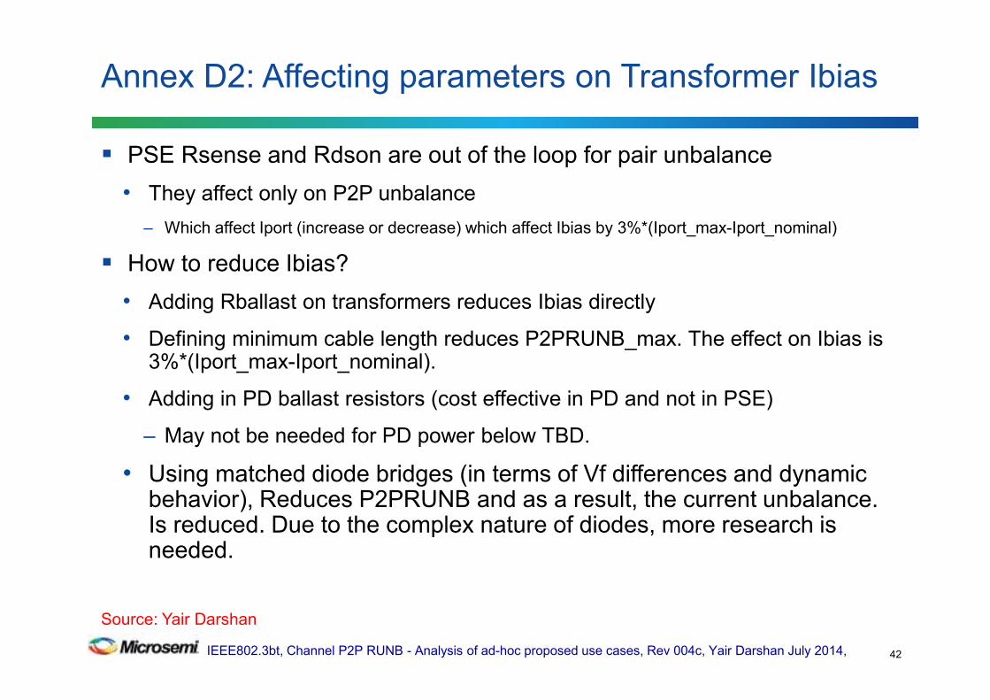
PSE Rsense and Rdson are out of the loop for pair unbalance
• They affect only on P2P unbalance
– Which affect Iport (increase or decrease) which affect Ibias by 3%*(Iport_max-Iport_nominal)
How to reduce Ibias?
• Adding Rballast on transformers reduces Ibias directly
• Defining minimum cable length reduces P2PRUNB_max. The effect on Ibias is 3%*(Iport_max-Iport_nominal).
• Adding in PD ballast resistors (cost effective in PD and not in PSE)
– May not be needed for PD power below TBD.
• Using matched diode bridges (in terms of Vf differences and dynamic behavior), Reduces P2PRUNB and as a result, the current unbalance. Is reduced. Due to the complex nature of diodes, more research is needed.
Annex D2: Affecting parameters on Transformer Ibias
42
Source: Yair Darshan
IEEE802.3bt, Channel P2P RUNB - Analysis of ad-hoc proposed use cases, Rev 004c, Yair Darshan July 2014,
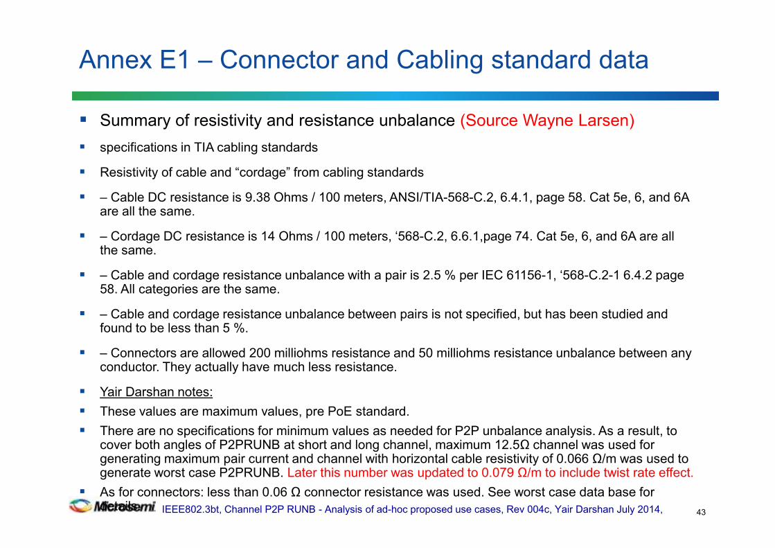
Summary of resistivity and resistance unbalance (Source Wayne Larsen)
specifications in TIA cabling standards
Resistivity of cable and “cordage” from cabling standards
– Cable DC resistance is 9.38 Ohms / 100 meters, ANSI/TIA-568-C.2, 6.4.1, page 58. Cat 5e, 6, and 6A are all the same.
– Cordage DC resistance is 14 Ohms / 100 meters, ‘568-C.2, 6.6.1,page 74. Cat 5e, 6, and 6A are all the same.
– Cable and cordage resistance unbalance with a pair is 2.5 % per IEC 61156-1, ‘568-C.2-1 6.4.2 page 58. All categories are the same.
– Cable and cordage resistance unbalance between pairs is not specified, but has been studied and found to be less than 5 %.
– Connectors are allowed 200 milliohms resistance and 50 milliohms resistance unbalance between any conductor. They actually have much less resistance.
Yair Darshan notes:
These values are maximum values, pre PoE standard.
There are no specifications for minimum values as needed for P2P unbalance analysis. As a result, to cover both angles of P2PRUNB at short and long channel, maximum 12.5Ω channel was used for generating maximum pair current and channel with horizontal cable resistivity of 0.066 Ω/m was used to generate worst case P2PRUNB. Later this number was updated to 0.079 Ω/m to include twist rate effect.
As for connectors: less than 0.06 Ω connector resistance was used. See worst case data base for details.
Annex E1 – Connector and Cabling standard data
43
IEEE802.3bt, Channel P2P RUNB - Analysis of ad-hoc proposed use cases, Rev 004c, Yair Darshan July 2014,
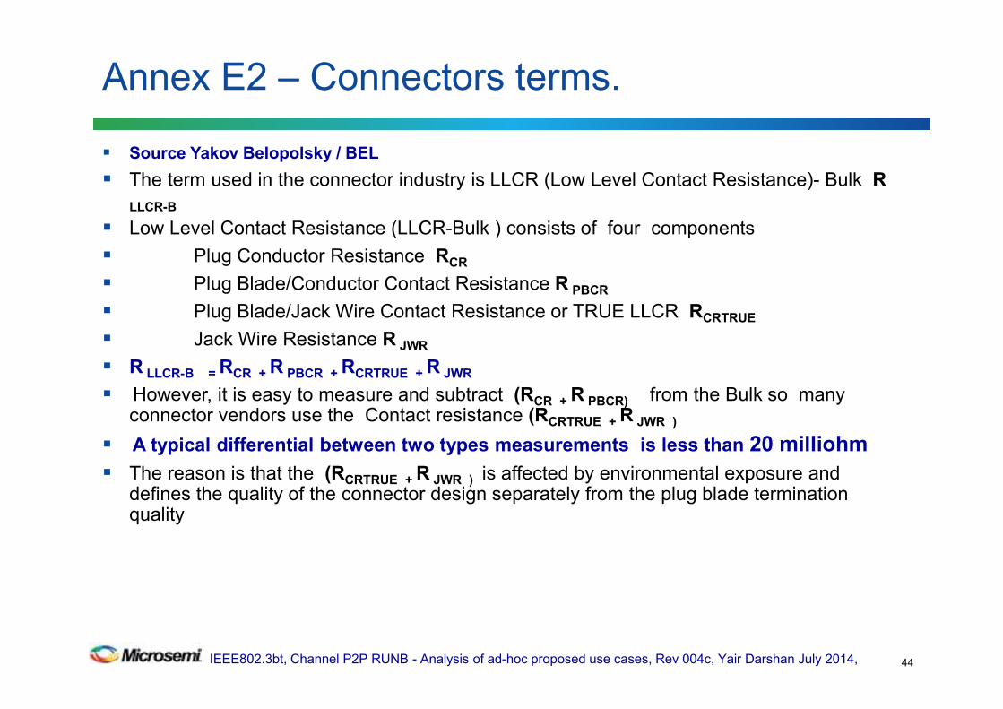
Source Yakov Belopolsky / BEL
The term used in the connector industry is LLCR (Low Level Contact Resistance)- Bulk R
LLCR-B
Low Level Contact Resistance (LLCR-Bulk ) consists of four components
Plug Conductor Resistance RCR
Plug Blade/Conductor Contact Resistance R PBCR
Plug Blade/Jack Wire Contact Resistance or TRUE LLCR RCRTRUE
Jack Wire Resistance R JWR
R LLCR-B = RCR + R PBCR + RCRTRUE + R JWR
However, it is easy to measure and subtract (RCR + R PBCR) from the Bulk so many connector vendors use the Contact resistance (RCRTRUE + R JWR )
A typical differential between two types measurements is less than 20 milliohm
The reason is that the (RCRTRUE + R JWR ) is affected by environmental exposure and defines the quality of the connector design separately from the plug blade termination quality
Annex E2 – Connectors terms.
44

IEEE802.3bt, Channel P2P RUNB - Analysis of ad-hoc proposed use cases, Rev 004c, Yair Darshan July 2014,
Vendor Resistance per datasheet
CAT6 A 30 milliohm max ,Jack only1
CAT6 B 35 milliohm max ,Jack only1
CAT6 C 30 milliohm max ,Jack only1
Annex E3: Connector data from vendors datasheet
45
1. It is per datasheet so actual values are lower.
Source: Yair Darshan
Source: Yair Darshan
IEEE802.3bt, Channel P2P RUNB - Analysis of ad-hoc proposed use cases, Rev 004c, Yair Darshan July 2014,
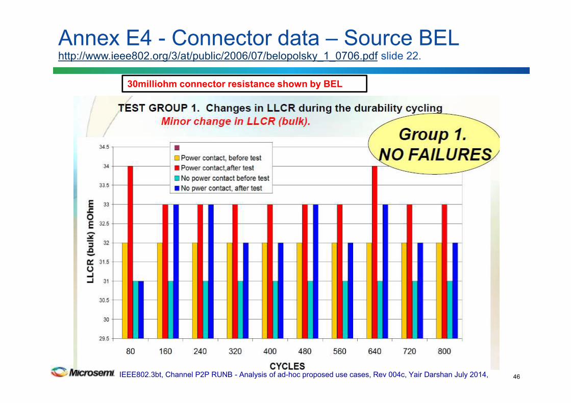
Annex E4 - Connector data – Source BELhttp://www.ieee802.org/3/at/public/2006/07/belopolsky_1_0706.pdf slide 22.
46
30milliohm connector resistance shown by BEL

IEEE802.3bt, Channel P2P RUNB - Analysis of ad-hoc proposed use cases, Rev 004c, Yair Darshan July 2014,
Connector # Vendor A Vendor B Vendor C Vendor D
CAT6 CAT6 CAT6A CAT6A
1 45 43 39 42 45
2 43 43 40 49 46
3 48 42 40 40 39
4 48 46 42 39 44
5 43 45 39 38 47
6 46 39 43 50 44
7 45 42 39 38 43
8 49 46 42 41 44
9 46 45 39 44 45
10 42 45 51 44
11 43 46 44 43
12 43 43 50 39
13 46 54 40
14 42 39 47
15 46 55 42
16 46 51 48
Annex E5: Connectors test data
47
Source: Microsemi
Each number in the table is the average resistance of all pins from end to end (Plug and Jack) for each connector.
Vendor A Vendor B Vendor C Vendor D
Average 45.08 44.06 40.33 44.53
Max 49 46 43 55
min 42 39 39 38
Rdiff 7 7 4 17
Average connector resistance 43.50
Max 55
Min 38
Rdiff 17
All connector resistance: 55milliΩ max.
• Vendors approve 60milliΩ max.
• There are high quality connector that get to 30milliΩ.
• The average resistance of these samples: 43.5milliΩ
Additional Information (not shown from the tables attached):
Within a connector, pair to pair resistance difference≤20milliΩ was confirmed.
Most results were below 15milliΩ, therefore this number chosen to be at the worst case data base table.
Simulations will be done for 15 and 20 milliohms as well.
Source: Yair Darshan
IEEE802.3bt, Channel P2P RUNB - Analysis of ad-hoc proposed use cases, Rev 004c, Yair Darshan July 2014,
See above link page 12.
45milliohm connector resistance of 40 connector samples.
See page 13 at the above link for connector resistance over temperature
Annex E6: Connectors test datahttp://www.vtiinstruments.com/Catalog/Technotes/RJ-45_Excels_For_Stria_Gage_Connection.pdf
48
Source: Yair Darshan.
Based on the above link.

IEEE802.3bt, Channel P2P RUNB - Analysis of ad-hoc proposed use cases, Rev 004c, Yair Darshan July 2014,
Annex F – End to End P2P Resistance Unbalance ModelGeneral Channel Model and its components that we have used.
49
Notes for the general Model:
1. Total end to end channel
connectors is 6 max.
2. The formal channel
definition is marked in red
arrow and is with up to 4
connectors.
3. Our work addresses also the
internal application
resistance of known
components that are used
4. In simulations, pairs 1 and 2
components were set to
minimum and pairs 3 and 4
were set to maximum
values. See simulation
results on previous meetings
5. Vofs1/2/3 and 4 was added.
To update the group. July 3,
2014.
Source: Yair Darshan and Christian Beia
IEEE802.3bt, Channel P2P RUNB - Analysis of ad-hoc proposed use cases, Rev 004c, Yair Darshan July 2014,
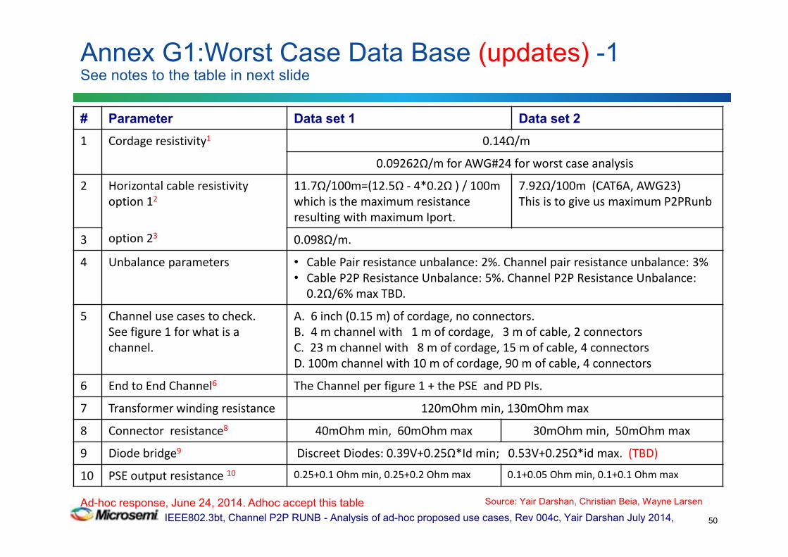
Annex G1:Worst Case Data Base (updates) -1See notes to the table in next slide
50
# Parameter Data set 1 Data set 2
1 Cordage resistivity1 0.14Ω/m
0.09262Ω/m for AWG#24 for worst case analysis
2 Horizontal cable resistivity
option 12
option 23
11.7Ω/100m=(12.5Ω - 4*0.2Ω ) / 100m
which is the maximum resistance
resulting with maximum Iport.
7.92Ω/100m (CAT6A, AWG23)
This is to give us maximum P2PRunb
3 0.098Ω/m.
4 Unbalance parameters • Cable Pair resistance unbalance: 2%. Channel pair resistance unbalance: 3%
• Cable P2P Resistance Unbalance: 5%. Channel P2P Resistance Unbalance:
0.2Ω/6% max TBD.
5 Channel use cases to check.
See figure 1 for what is a
channel.
A. 6 inch (0.15 m) of cordage, no connectors.
B. 4 m channel with 1 m of cordage, 3 m of cable, 2 connectors
C. 23 m channel with 8 m of cordage, 15 m of cable, 4 connectors
D. 100m channel with 10 m of cordage, 90 m of cable, 4 connectors
6 End to End Channel6 The Channel per figure 1 + the PSE and PD PIs.
7 Transformer winding resistance 120mOhm min, 130mOhm max
8 Connector resistance8 40mOhm min, 60mOhm max 30mOhm min, 50mOhm max
9 Diode bridge9 Discreet Diodes: 0.39V+0.25Ω*Id min; 0.53V+0.25Ω*id max. (TBD)
10 PSE output resistance 10 0.25+0.1 Ohm min, 0.25+0.2 Ohm max 0.1+0.05 Ohm min, 0.1+0.1 Ohm max
Ad-hoc response, June 24, 2014. Adhoc accept this table Source: Yair Darshan, Christian Beia, Wayne Larsen

IEEE802.3bt, Channel P2P RUNB - Analysis of ad-hoc proposed use cases, Rev 004c, Yair Darshan July 2014,
1 Per standard. It is maximum value for solid and stranded wire. The maximum value is close to AWG#26 wire
resistance/meter including twist rate effects. See annex E1. Due to the fact that patch cords may use AWG#24 cables with
stranded (for mechanical flexibility) or solid wire (for improved performance), we will use the AWG#24A for worst case analysis as
well. Cordage with AWG#24 wire has 0.0842Ω/m for solid wire and with 10% twist rate it will be 0.09262 Ω/m.
2 We need both data sets (data set 1 and data set 2) to find where is the worst condition for maximum current unbalance. See
Annex B curve and data showing that at short channel we get maximum P2PRUNB but it may has less concern to us since the
current is lower. We need to do all use cases calculation to see where is the maximum current over the pair; at short channel or
long channel. The CAT6A cable with AWG#23 has 0.066 Ω/m. Including 12% increase on cable length due to twist rate, the
effective cable resistance per meter will be 1.12*6.6 Ω/100m= 0.0792 Ω/m.
3 Standard definition per Annex E1. We will check how results will be differ when AWG#23 is used for worst case results (lower
resistance than standard definition for horizontal cable which is a maximum value.
4
5
6 PSE PI and PD PI includes: connector, transformer, resistors. PD PI includes diode bridge.
7
8 Connector resistance was changed since the difference (60-30) milliohm is not representing Rdiff, it is representing maximum and
minimum results of connector resistance of different connectors. To correct it, we change the numbers according to inputs from
connector vendors and measured data. See Annex E1-E6 for confirmation.
9 Vf and Rd are worst case numbers of discrete diode which there is no control on Vf and Rd. It needs more investigation to verify
that we are not over specify. (Christian is checking it). Normally match components (e.g. matched two diode bridges) are used for
4P operation. Any how ,PD PI spec. will eventually set the requirement.
10 PSE output resistance e.g. Rs_a/b=Rsense+Rdson in addition to winding resistance. See model I Annex F for reference.
Annex G2: Worst case data base- Notes. -2
51
Adhoc response, June 24, 2014. Adhoc accept this table Source: Yair Darshan and Christian Beia

IEEE802.3bt, Channel P2P RUNB - Analysis of ad-hoc proposed use cases, Rev 004c, Yair Darshan July 2014,
Connector vendors: connector resistance rage of different connectors for worst case lowest numbers: 0.03Ω to 0.06 Ω. (Standard is 200milliohm max and Rdiff=50milliohm max which is not helping us).
With in a connector (pin to pin or pair to pair), the difference between Rmax and Rmin (=Rdiff) is 0.02Ωmax, Typically it is not more than 0.015Ω. (instead 0.03Ω).
As a result, for worst case calculation we will use for connectors:
• Connector Rmax=0.05Ω, Connector Rdiff=0.02Ω max.
Cordage: 0.14 Ω/m per standard. Cable: 0.0792Ω/m for CAT6A AWG#23 cable for worst case analysis.
Annex G3: Deciding on Channel components data
52
Connector data combinations that don’t make sense.
# Rmax milliΩ Rdif milliΩ Rmin milliΩ Notes
1 201 - - 200milliΩ max, standard
2 - 51 - 50milliΩ max, standard
3 60 50 10 Meets the standard however
doesn’t make sense to have
71.4% P2PRUNB.
4 61 - - Field results, 60milliΩ max
5 - 30 - Field results, 20milliΩ max
Connector data combinations that make sense.
6 60 20 40 OK
7 50 20 30 OK for worst case.
Adhoc response, June 24, 2014. Adhoc accept this table Source: Yair Darshan
IEEE802.3bt, Channel P2P RUNB - Analysis of ad-hoc proposed use cases, Rev 004c, Yair Darshan July 2014,
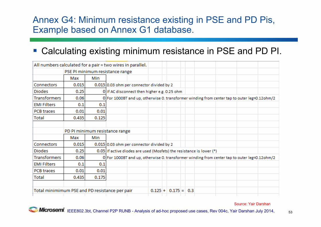
Calculating existing minimum resistance in PSE and PD PI.
Annex G4: Minimum resistance existing in PSE and PD Pis, Example based on Annex G1 database.
53
Source: Yair Darshan

IEEE802.3bt, Channel P2P RUNB - Analysis of ad-hoc proposed use cases, Rev 004c, Yair Darshan July 2014,
(1) Pair resistance unbalance : Is the resistance unbalance between two wires in the
same pair as specified by IEEE802.3 and other standards. This is 2% for cable and 3%
maximum for the channel. Channel is a 4 connector model (cables and connector only).
(2) Pair to Pair resistance unbalance: is the resistance unbalance between two wires of
the same pair connected in parallel to another two wires of other pair connected in parallel.
It is 5% for a cable.
(The resistance of the two wires of the pair is know also as the common mode resistance
of the pair)
(3) End to End channel pair to pair resistance unbalance it is the 26.2% (TBD) worst
case calculation on a worst case data base that we have generated. The 26.2% (TBD) was
calculated at 20degC. The channel is including components at PSE PI and PD PI that
affects the whole end to end channel.
(4) PSE PI Pair to Pair resistance unbalance is the P2P DC Common Mode PSE Output
Resistance Unbalance measured at the PSE PI and include PI interface circuitry such
RDSON, Current sense resistor, equipment connector, magnetic winding resistance. This is
included in the " end to end channel resistance unbalance" and need to be extracted from it
to be separate definition for PSE PI P2PRUNB.
(4.1) PSI PI Pair to Pair voltage difference is the P2P DC Common Mode PSE Output
Voltage Difference measured at the PSE PI under TBD conditions.
Annex J1-Acronyms used in the ad-hoc activity
54
Source: Yair Darshan
IEEE802.3bt, Channel P2P RUNB - Analysis of ad-hoc proposed use cases, Rev 004c, Yair Darshan July 2014,
(5) PD PI Pair to Pair resistance unbalance is the P2P DC Common Mode PD
input Resistance Unbalance measured at the PD PI and include PI interface
circuitry such Diode bridge voltage offset and dynamic resistance, equipment
connector, magnetic winding resistance. This is included in the "end to end
channel resistance unbalance" and need to be extracted from it to be separate
definition for PD PI P2PRUNB.
(5.1) PD PI Pair to Pair voltage difference is the P2P DC Common Mode PD
input Voltage Difference measured at the PD PI under TBD conditions.
(6) Channel Pair to Pair resistance unbalance is the P2P resistance
unbalance of the cables and 4 connector model. This need to be excreted from
the " end to end channel resistance unbalance" and specified separately.
So (PSE PI +Channel + PD PI)p2prunb all together is 26.2% (TBD).
Items 4,5 and 6 will be specified in the standard, (item 2 is covered by item 6).
Meeting #4: Adhoc response: ok. Meeting #5: To discuss changes in RED. Done.
Annex J2-Acronyms used in the ad-hoc activity
55
Source: Yair Darshan
IEEE802.3bt, Channel P2P RUNB - Analysis of ad-hoc proposed use cases, Rev 004c, Yair Darshan July 2014,
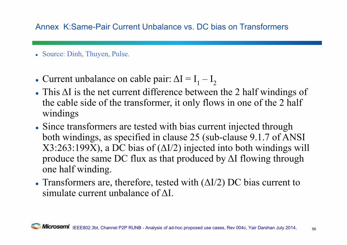
Source: Dinh, Thuyen, Pulse.
Current unbalance on cable pair: ∆I = I1
– I2
This ∆I is the net current difference between the 2 half windings of the cable side of the transformer, it only flows in one of the 2 half windings
Since transformers are tested with bias current injected through both windings, as specified in clause 25 (sub-clause 9.1.7 of ANSI X3:263:199X), a DC bias of (∆I/2) injected into both windings will produce the same DC flux as that produced by ∆I flowing through one half winding.
Transformers are, therefore, tested with (∆I/2) DC bias current to simulate current unbalance of ∆I.
Annex K:Same-Pair Current Unbalance vs. DC bias on Transformers
56
IEEE802.3bt, Channel P2P RUNB - Analysis of ad-hoc proposed use cases, Rev 004c, Yair Darshan July 2014,
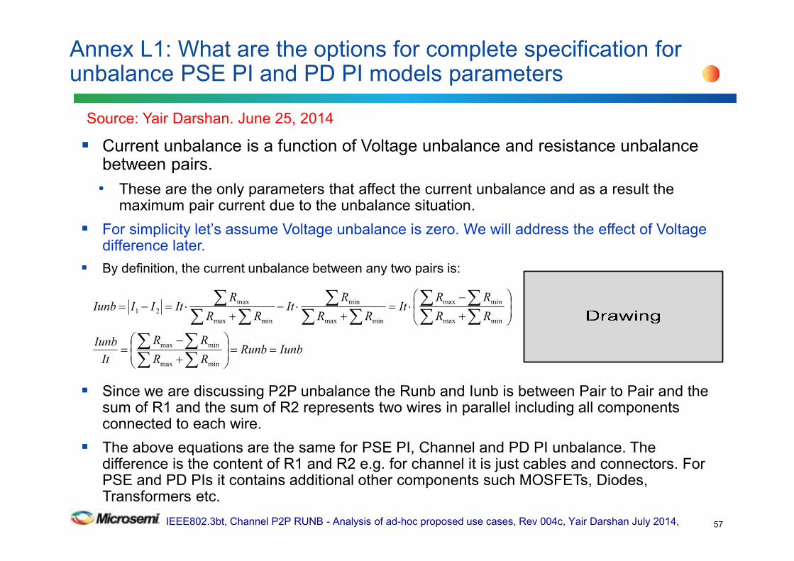
Current unbalance is a function of Voltage unbalance and resistance unbalance between pairs.
• These are the only parameters that affect the current unbalance and as a result the maximum pair current due to the unbalance situation.
For simplicity let’s assume Voltage unbalance is zero. We will address the effect of Voltage difference later.
By definition, the current unbalance between any two pairs is:
Since we are discussing P2P unbalance the Runb and Iunb is between Pair to Pair and the sum of R1 and the sum of R2 represents two wires in parallel including all components connected to each wire.
The above equations are the same for PSE PI, Channel and PD PI unbalance. The difference is the content of R1 and R2 e.g. for channel it is just cables and connectors. For PSE and PD PIs it contains additional other components such MOSFETs, Diodes, Transformers etc.
Annex L1: What are the options for complete specification for unbalance PSE PI and PD PI models parameters
57
Source: Yair Darshan. June 25, 2014
IunbRunbRR
RR
It
Iunb
RR
RRIt
RR
RIt
RR
RItIIIunb
==
+
−=
+
−⋅=
+⋅−
+⋅=−=
∑∑∑∑
∑∑∑∑
∑∑∑
∑∑∑
minmax
minmax
minmax
minmax
minmax
min
minmax
max
21

IEEE802.3bt, Channel P2P RUNB - Analysis of ad-hoc proposed use cases, Rev 004c, Yair Darshan July 2014,
The maximum pair current is function of the total End to End Channel Resistance and Voltage Unbalance.
The PSE PI and PD PI are affecting Imax at short and long channels.
By definition for maximum pair current Imax as function of P2PRUNB and P2P Voltage Difference of the system from end to end:
The PSE PI P2PRUNB can be defined in similar way by similarity.
Note: PSE PI P2PRUNB is not equal to E2E_CPWPRUNB nor to PD PI P2PRUN. It requires additional mathematical procedure to find this parameters so it will be equal to the E2E_CP2PRUNB target.
Annex L2: What are the options for complete specification for unbalance PSE PI and PD PI models parameters
58
2
)2_21(
2
2_2
2Im
PRUNBPEEItPRUNBPEEItItax
+⋅=
⋅+=
( ) ( ) ( )
2
1
2
)2_21(Im
minminminmaxmaxmax
minmaxminmaxminmax
+++++
−+−+−+⋅
=+⋅
=∑∑∑∑∑∑∑∑∑ ∑∑∑
CH
R
PD
R
PSE
R
CH
R
PD
R
PSE
R
CH
R
CH
R
PD
R
PD
R
PSE
R
PSE
RIt
PRUNBPEEItax
2
1
2
)2_21(Im
minminminmaxmaxmax
+++++
+++⋅
=+⋅
=∑∑∑∑∑∑
∑∑∑CH
R
PD
R
PSE
R
CH
R
PD
R
PSE
R
CH
R
PD
R
PSE
R diffdiffdiffIt
PRUNBPEEItax
Source: Yair Darshan

IEEE802.3bt, Channel P2P RUNB - Analysis of ad-hoc proposed use cases, Rev 004c, Yair Darshan July 2014,
We can see that Imax is function of Rmax and Rmin and Rdiff=Rmax-Rmin
From the above, PSE PI P2PRUNB upper limit can be extracted and it will have the same effect on Imax with the same exact concept.
The terms k, a and b are used to transform the true PSE PI P2PRUNB to PSE PI P2PRUNB as stand alone function.
Now we can see what are the necessary unbalanced properties that are needed to uniquely specify the PSE PI?
Annex L3: What are the options for complete specification for unbalance PSE PI and PD PI models parameters
59
2
1
2
)2_21(Im
minminminmaxmaxmax
+++++
+++⋅
=+⋅
=∑∑∑∑∑∑
∑∑∑CH
R
PD
R
PSE
R
CH
R
PD
R
PSE
R
CH
R
PD
R
PSE
R diffdiffdiffIt
PRUNBPEEItax
∑∑∑∑∑∑∑
+++++=
CH
R
PD
R
PSE
R
CH
R
PD
R
PSE
R
PSE
RdiffPRUNBPPIPSE
minminminmaxmaxmax
2__
( )∑∑
∑∑∑∑
+=
++
⋅+=
PSE
newR
PSE
R
PSE
newR
PSE
R
PSE
R
PSE
R
new
diffdiffk
PRUNBPPIPSE_
_
minmax_minmax
2__β
α
Source: Yair Darshan

IEEE802.3bt, Channel P2P RUNB - Analysis of ad-hoc proposed use cases, Rev 004c, Yair Darshan July 2014,
Conclusions: In order to limit Imax_pair you must have in addition to voltage difference and maximum load current It, two additional parameters.
Firs and fast observation: Imax is equation with 3 parameters. Total current, It is given. We need two variable to solve equation with two parameters
So specifying only Rdiff and Vdiff for PSE PI or PD PI will not work. It leads to interoperability issues. (one parameter is loose..)
Annex L4: What are the options for complete specification for unbalance PSE PI and PD PI models parameters
60
++⋅⋅=
+
−=
+=
∑∑∑
∑∑∑∑
∑∑∑
PSE
newR
PSE
R
PSE
newR
PSE
newR
PSE
R
PSE
newR
PSE
R
PSE
newR
PSE
R
PSE
newR
new
diff
new
new
new
diff
Itax
PRUNBPPIPSE
_
_
_
_
_
_
minmax_
minmax_
minmax_
minmax_
15.0Im
2__
Source: Yair Darshan
IEEE802.3bt, Channel P2P RUNB - Analysis of ad-hoc proposed use cases, Rev 004c, Yair Darshan July 2014,
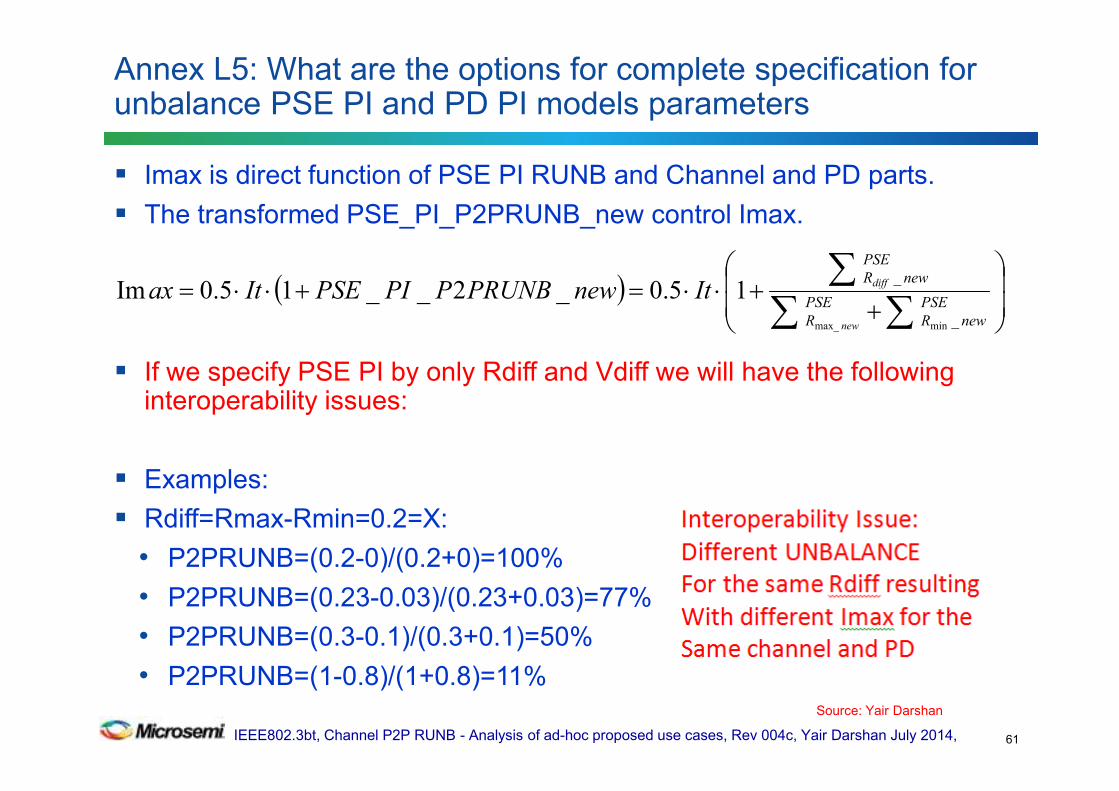
Imax is direct function of PSE PI RUNB and Channel and PD parts.
The transformed PSE_PI_P2PRUNB_new control Imax.
If we specify PSE PI by only Rdiff and Vdiff we will have the following interoperability issues:
Examples:
Rdiff=Rmax-Rmin=0.2=X:
• P2PRUNB=(0.2-0)/(0.2+0)=100%
• P2PRUNB=(0.23-0.03)/(0.23+0.03)=77%
• P2PRUNB=(0.3-0.1)/(0.3+0.1)=50%
• P2PRUNB=(1-0.8)/(1+0.8)=11%
Annex L5: What are the options for complete specification for unbalance PSE PI and PD PI models parameters
61
( )
++⋅⋅=+⋅⋅=
∑∑∑
PSE
newR
PSE
R
PSE
newR
new
diffItnewPRUNBPPIPSEItax
_
_
minmax_
15.0_2__15.0Im
Source: Yair Darshan
IEEE802.3bt, Channel P2P RUNB - Analysis of ad-hoc proposed use cases, Rev 004c, Yair Darshan July 2014,
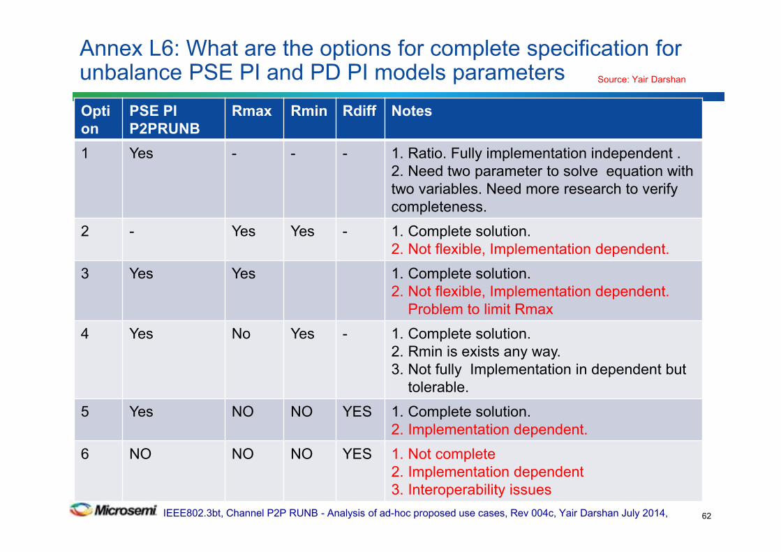
Annex L6: What are the options for complete specification for unbalance PSE PI and PD PI models parameters
62
Opti
on
PSE PI
P2PRUNB
Rmax Rmin Rdiff Notes
1 Yes - - - 1. Ratio. Fully implementation independent .
2. Need two parameter to solve equation with
two variables. Need more research to verify
completeness.
2 - Yes Yes - 1. Complete solution.
2. Not flexible, Implementation dependent.
3 Yes Yes 1. Complete solution.
2. Not flexible, Implementation dependent.
Problem to limit Rmax
4 Yes No Yes - 1. Complete solution.
2. Rmin is exists any way.
3. Not fully Implementation in dependent but
tolerable.
5 Yes NO NO YES 1. Complete solution.
2. Implementation dependent.
6 NO NO NO YES 1. Not complete
2. Implementation dependent
3. Interoperability issues
Source: Yair Darshan
IEEE802.3bt, Channel P2P RUNB - Analysis of ad-hoc proposed use cases, Rev 004c, Yair Darshan July 2014,
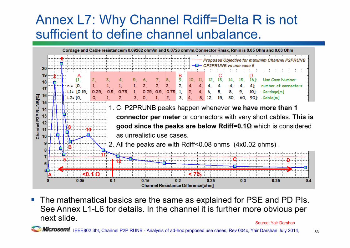
The mathematical basics are the same as explained for PSE and PD PIs. See Annex L1-L6 for details. In the channel it is further more obvious per next slide.
Annex L7: Why Channel Rdiff=Delta R is not sufficient to define channel unbalance.
63
1. C_P2PRUNB peaks happen whenever we have more than 1
connector per meter or connectors with very short cables. This is
good since the peaks are below Rdiff=0.1Ω which is considered
as unrealistic use cases.
2. All the peaks are with Rdiff<0.08 ohms (4x0.02 ohms) .
2
6
B
C D
10
5 12
A
11
<0.1 Ω < 7%
8
Source: Yair Darshan

IEEE802.3bt, Channel P2P RUNB - Analysis of ad-hoc proposed use cases, Rev 004c, Yair Darshan July 2014,
If we will specify Channel P2P RUNB by its Rmax-Rmin=Rdiff=0.1Ω (or any number) property only we will end with the following undesired results:
(a) At long channel (high resistance) the unbalance is converging to lowest possible value. It is bounded by the P2PRUNB[%] property which is much lower than the connectors unbalance property.
(b) At short channel when resistance is low, the P2PRUNB property is bounded by the connectors Rmax, Rmin which results with 25% unbalance for Rmax=0.05Ω, Rmin=0.03Ω Rdiff=0.02 Ω (50-30)/(50+30)=25%
So it is obvious that best and optimized performance will be achieved with two properties needed for the channel: P2PRUNB and Rdiff.
Annex L8: Why Channel Rdiff=Delta R is not sufficient to define channel unbalance.
64
Source: Yair Darshan
IEEE802.3bt, Channel P2P RUNB - Analysis of ad-hoc proposed use cases, Rev 004c, Yair Darshan July 2014,
Adhoc has recommended the following approach (meetings 5,6,7)
• How to handle PSE PI, PD PI Pair to Pair unbalance parameters and Channel P2RUNB as function of temperature?
– Adhoc response:
– Use PSE PI, PD PI pair to pair Unbalance parameters and Channel P2PRUNB that was calculated at 20°.
– Set it as the number to meet without saying at what temperature it is.
– Vendors will have to assure that they meet it at their operating temperature range spec.
– How they will do it, we don’t care. The rest is per 33.7.7.
Annex M: How we address P2PRUNB vs Temperature
65
Ad-hoc response, June 10, 2014. Ad hoc agrees to set temperature of P2PUNB numbers at 20degC.
IEEE802.3bt, Channel P2P RUNB - Analysis of ad-hoc proposed use cases, Rev 004c, Yair Darshan July 2014,
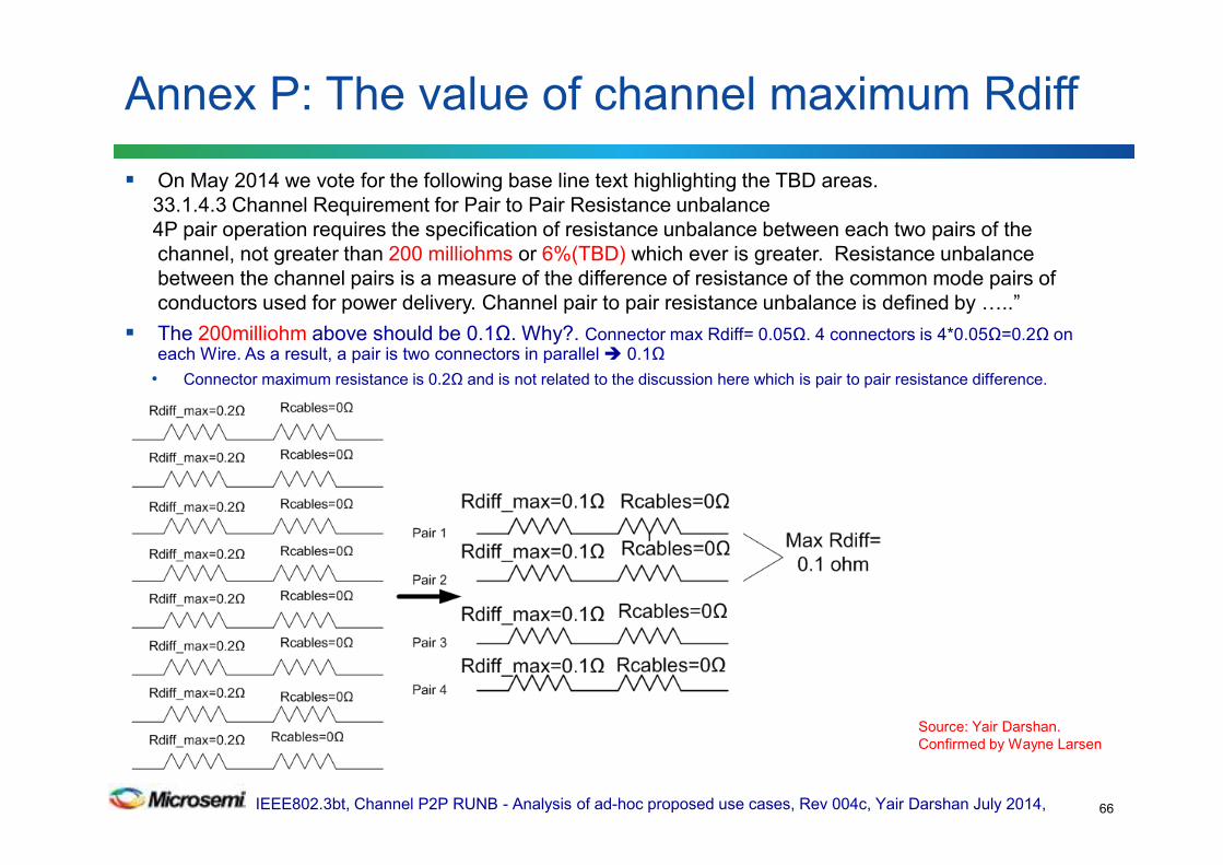
On May 2014 we vote for the following base line text highlighting the TBD areas.
33.1.4.3 Channel Requirement for Pair to Pair Resistance unbalance
4P pair operation requires the specification of resistance unbalance between each two pairs of the
channel, not greater than 200 milliohms or 6%(TBD) which ever is greater. Resistance unbalance
between the channel pairs is a measure of the difference of resistance of the common mode pairs of
conductors used for power delivery. Channel pair to pair resistance unbalance is defined by J..”
The 200milliohm above should be 0.1Ω. Why?. Connector max Rdiff= 0.05Ω. 4 connectors is 4*0.05Ω=0.2Ω on each Wire. As a result, a pair is two connectors in parallel 0.1Ω
• Connector maximum resistance is 0.2Ω and is not related to the discussion here which is pair to pair resistance difference.
Annex P: The value of channel maximum Rdiff
66
Source: Yair Darshan.
Confirmed by Wayne Larsen
IEEE802.3bt, Channel P2P RUNB - Analysis of ad-hoc proposed use cases, Rev 004c, Yair Darshan July 2014,
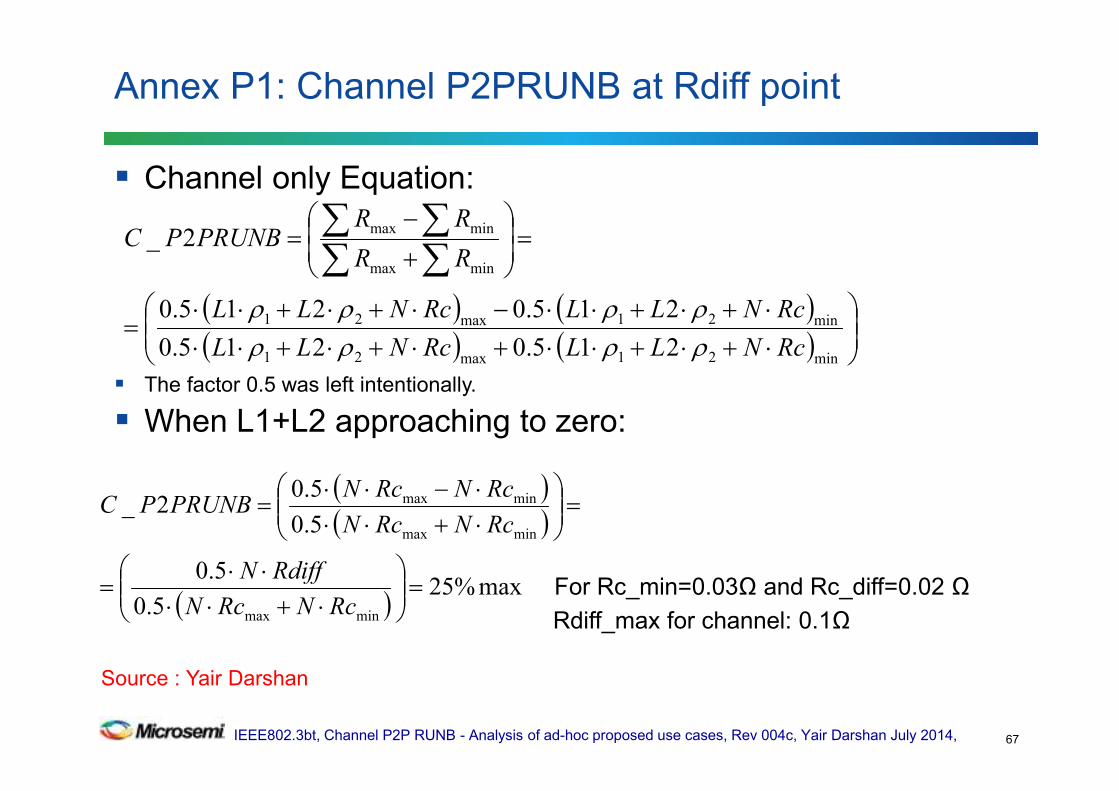
Channel only Equation:
The factor 0.5 was left intentionally.
When L1+L2 approaching to zero:
For Rc_min=0.03Ω and Rc_diff=0.02 Ω
Rdiff_max for channel: 0.1Ω
Annex P1: Channel P2PRUNB at Rdiff point
67
( ) ( )( ) ( )
⋅+⋅+⋅⋅+⋅+⋅+⋅⋅
⋅+⋅+⋅⋅−⋅+⋅+⋅⋅=
=
+
−=
∑∑∑∑
min21max21
min21max21
minmax
minmax
215.0215.0
215.0215.0
2_
RcNLLRcNLL
RcNLLRcNLL
RR
RRPRUNBPC
ρρρρρρρρ
( )( )
( )max%25
5.0
5.0
5.0
5.02_
minmax
minmax
minmax
=
⋅+⋅⋅⋅⋅
=
=
⋅+⋅⋅⋅−⋅⋅
=
RcNRcN
RdiffN
RcNRcN
RcNRcNPRUNBPC
Source : Yair Darshan
IEEE802.3bt, Channel P2P RUNB - Analysis of ad-hoc proposed use cases, Rev 004c, Yair Darshan July 2014,
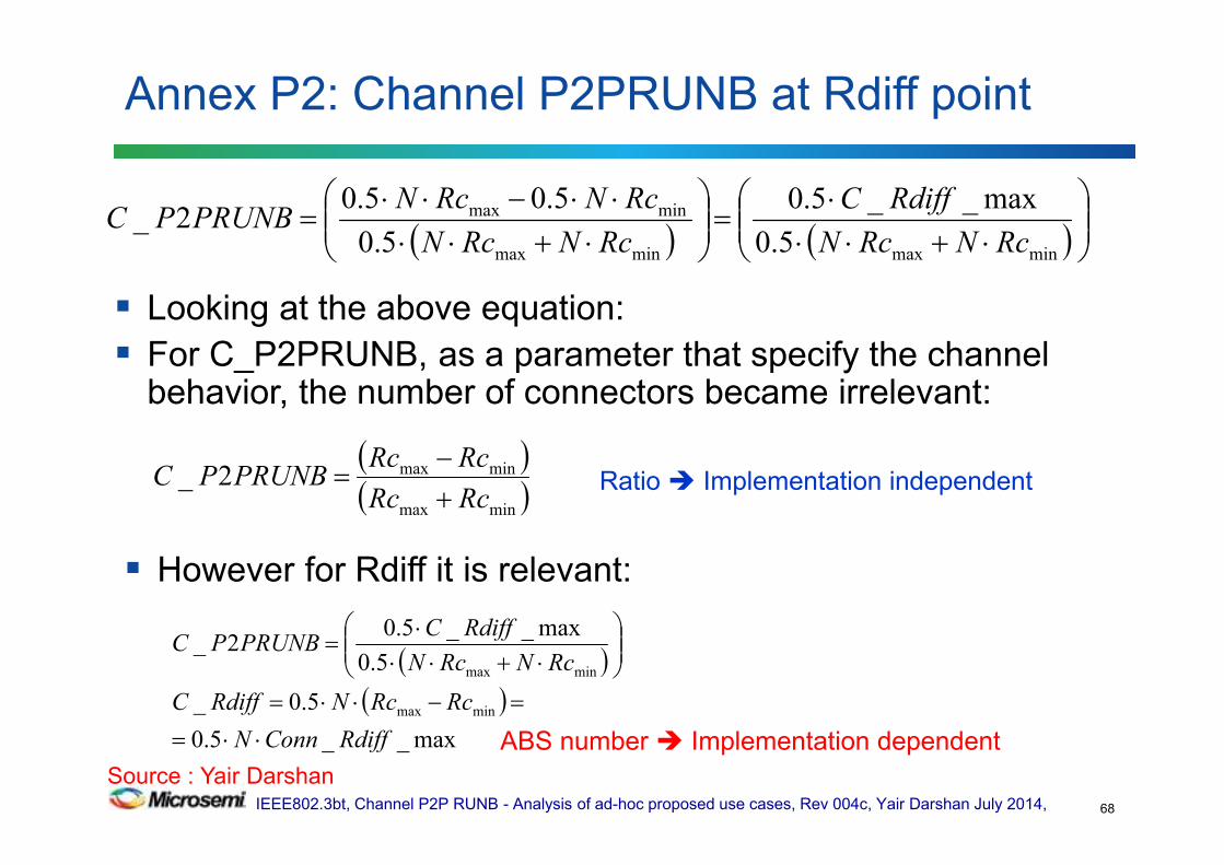
Looking at the above equation:
For C_P2PRUNB, as a parameter that specify the channel behavior, the number of connectors became irrelevant:
Annex P2: Channel P2PRUNB at Rdiff point
68
( ) ( )
⋅+⋅⋅⋅
=
⋅+⋅⋅⋅⋅−⋅⋅
=minmaxminmax
minmax
5.0
max__5.0
5.0
5.05.02_
RcNRcN
RdiffC
RcNRcN
RcNRcNPRUNBPC
( )( )minmax
minmax2_RcRc
RcRcPRUNBPC
+−
=
However for Rdiff it is relevant:
( )( )
max__5.0
5.0_
5.0
max__5.02_
minmax
minmax
RdiffConnN
RcRcNRdiffC
RcNRcN
RdiffCPRUNBPC
⋅⋅=
=−⋅⋅=
⋅+⋅⋅⋅
=
Ratio Implementation independent
ABS number Implementation dependent
Source : Yair Darshan

IEEE802.3bt, Channel P2P RUNB - Analysis of ad-hoc proposed use cases, Rev 004c, Yair Darshan July 2014,
Complete Channel specification: (Complete specification is like defining the behavior of equation for its entire
operating range and as close as possible to implementation independent)
For
For
Which ever is greater
Annex P3: Channel P2PRUNB at Rdiff point
69
( ) ( )( ) ( )
max%5.72121
21212_
min21max21
min21max21 =
⋅+⋅+⋅+⋅+⋅+⋅
⋅+⋅+⋅−⋅+⋅+⋅=
RcNLLRcNLL
RcNLLRcNLLPRUNBPC
ρρρρρρρρ
Ω=⋅⋅> 1.0max__5.0_ RdiffConnNRdiffC
Ω=⋅⋅≤ 1.0max__5.0_ RdiffConnNRdiffC
Ω=⋅⋅= 1.0max__5.0max__ RdiffConnNRdiffC
( )( )
%25max_2_minmax
minmax =+−
=RcRc
RcRcPRUNBPC
Numbers are based on worst case data base numbers Source : Yair Darshan

IEEE802.3bt, Channel P2P RUNB - Analysis of ad-hoc proposed use cases, Rev 004c, Yair Darshan July 2014,
Rmin is given as round loop value.
Rc_max=0.05 ,Rc_min=0.03, β=Cable_P2PRUNB=5%
Channel_P2PRUNB=α=7% as an example.
Annex Q: Channel Rmin vs. Channel P2PRUNB and number of connectors
70
( ) ( )
( ) ( )( ) ( )( ) ( )( ) ( ) ( )( ) ( ) ( ) ( )( ) ( ) ( ) ( )( ) ( )( ) ( ) ( )( ) ( )
( ) ( )11
11
11
11
11
1
1
)(1
)(1max_
min_
2_
2_
minmaxminmaxmin
minmaxminmaxmin
minmaxminmaxminmin
minminmaxminminmax
minminmaxminminmax
minminmax
minminmax
minminmaxmax
minminmaxmax
minminmax
min
−−+⋅+⋅⋅−−⋅
=
+⋅⋅−−⋅=−−+⋅⋅
+⋅⋅−−⋅=−⋅−+⋅⋅
−⋅+−⋅=+⋅⋅++⋅⋅
−⋅+−⋅=+⋅++⋅⋅
=+⋅++⋅−⋅+−⋅
=
=⋅++⋅+⋅+−⋅+
=
⋅=−+
⋅==
=
=
=
δδαα
αδδα
αδδα
δδαα
δδα
δδ
α
α
δββ
βα
RcRcNRcRcNR
RcRcNRcRcNR
RcRcNRcRcNRR
RRcRcNRRcRcN
RRcRcNRRcRcN
RRcRcN
RRcRcN
RcNRRcNR
RcNRRcNR
RRRRcable
RRcable
PRUNBPCable
PRUNBPChannel
( ) ( )( ) ( )11
minmaxminmaxmin −−+⋅
+⋅⋅−−⋅=
δδαα RcRcNRcRcN
R
Source : Yair Darshan.Verified by analytical solution and simulations