chap7
DESCRIPTION
cdmaTRANSCRIPT

1
Chapter 7 Spread-Spectrum Modulation
Spread Spectrum Technique simply consumes spectrum in excess of the minimum spectrumnecessary to send the data.
© Po-Ning [email protected] Chapter 7-2
7.1 Introduction
Definition of spread-spectrum modulationWeakly sense
Occupy a bandwidth that is much larger than the minimum bandwidth (1/2T) necessary to transmit a data sequence.
Strict senseSpectrum is spreading by means of a pseudo-white or pseudo-noise code.

2
© Po-Ning [email protected] Chapter 7-3
7.2 Pseudo-noise sequences
A (digital) code sequence that mimics the (second-order) statistical behavior of a white noise.For example,
balance propertyrun propertycorrelation property
From implementation standpoint, the most convenient way to generate a pseudo-noise sequence is to employ several shift-registers and a feedback through combinational logic.
© Po-Ning [email protected] Chapter 7-4
7.2 Pseudo-noise sequences
Exemplified block diagram of PN sequence generators
Feedback shift register becomes “linear” if the feedback logic consists entirely of modulo-2 adders.

3
© Po-Ning [email protected] Chapter 7-5
7.2 Pseudo-noise sequences
Example of linear feedback shift register
© Po-Ning [email protected] Chapter 7-6
7.2 Pseudo-noise sequences
A PN sequence generated by a feedback shift register must eventually become periodic with period at most 2m, where m is the number of shift registers.A PN sequence generated by a linear feedback shift register must eventually become periodic with period at most 2m − 1, where m is the number of shift registers.A PN sequence whose period reaches its maximum value is named the maximum-length sequence or simply m-sequence.

4
© Po-Ning [email protected] Chapter 7-7
7.2 Pseudo-noise sequences
A maximum-length sequence generated from a linear shift register satisfies all three properties:
Balance propertyThe number of 1s is one more than that of 0s.
Run property (total number of runs = 2m−1)½ of the runs is of length 1¼ of the runs is of length 2…
© Po-Ning [email protected] Chapter 7-8
Correlation propertyAutocorrelation of an ideal discrete white process = a·δ[τ], where δ[τ] is the Kroneckerdelta function.
7.2 Pseudo-noise sequences
5
© Po-Ning [email protected] Chapter 7-9
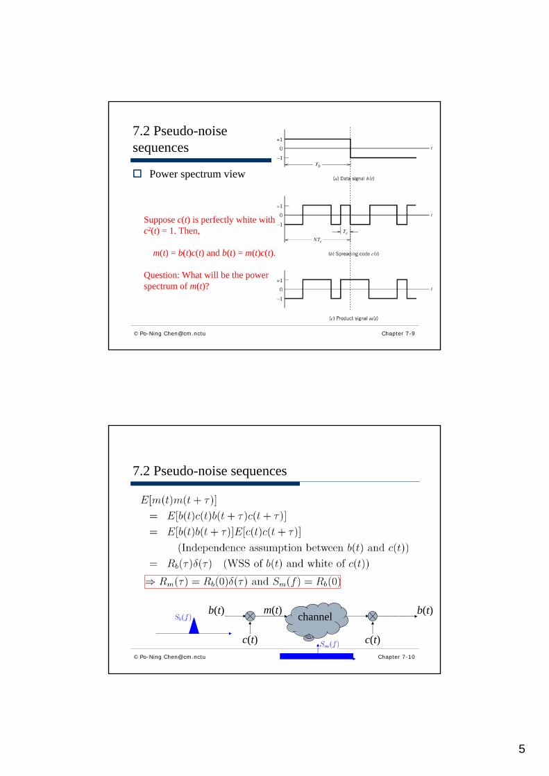
7.2 Pseudo-noise sequences
Power spectrum view
Suppose c(t) is perfectly white with c2(t) = 1. Then,
m(t) = b(t)c(t) and b(t) = m(t)c(t).
Question: What will be the power spectrum of m(t)?
© Po-Ning [email protected] Chapter 7-10
7.2 Pseudo-noise sequences
b(t)
c(t)
m(t) channel b(t)
c(t)

6
© Po-Ning [email protected] Chapter 7-11
7.2 Pseudo-noise sequences
Please self-study Example 7.2 for examples of the m-sequences.
Its understanding will be part of the exam.
© Po-Ning [email protected] Chapter 7-12
7.3 A notion of spread spectrum
b(t)
c(t)
m(t) channel b(t)
c(t)
Make the transmitted signal to blend (and hide behind) the background noise.
Spreading code

7
© Po-Ning [email protected] Chapter 7-13
7.3 A notion of spread spectrum
channel receivertransmitter
Lowpass filter that (only) allows signal b(t) to pass!
© Po-Ning [email protected] Chapter 7-14
7.4 Direct-sequence spread spectrum with coherent binary phase-shift keying
DSSS system
transmitter
receiver

8
© Po-Ning [email protected] Chapter 7-15
© Po-Ning [email protected] Chapter 7-16
(As the conceptual system below.)

9
© Po-Ning [email protected] Chapter 7-17
7.5 Signal-space dimensionality and processing gain
SNR before spreading
SNR after spreading
Orthonormal basis used at the receiver end
Assume “coherent detection”.In other words, perfect synchronization and no phase mismatch.
SNR before spreading
© Po-Ning [email protected] Chapter 7-18

10
SNR after spreading
© Po-Ning [email protected] Chapter 7-19
© Po-Ning [email protected] Chapter 7-20
11
© Po-Ning [email protected] Chapter 7-21
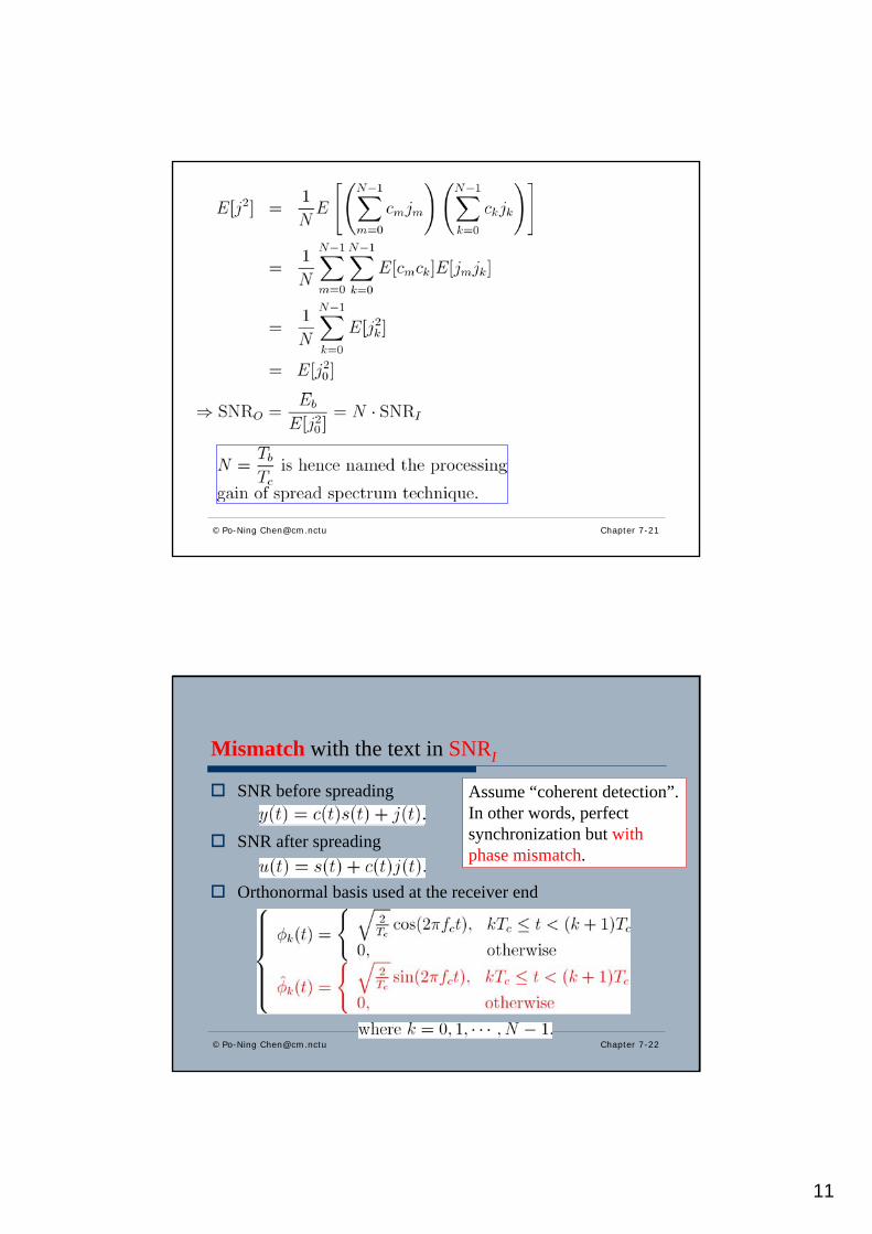
Mismatch with the text in SNRI
SNR before spreading
SNR after spreading
Orthonormal basis used at the receiver end
© Po-Ning [email protected] Chapter 7-22
Assume “coherent detection”.In other words, perfect synchronization but with phase mismatch.

12
SNR before spreading
© Po-Ning [email protected] Chapter 7-23
© Po-Ning [email protected] Chapter 7-24
The factor 2 enters when the “phase” is assumed unknown to the before-spreading receiver; hence, both cosine and sinedomains must be “inner-producted”. If the “phase” is also assumed unknown to the after-spreading receiver, then the fact 2 in SNRI/SNRO formula will (again) disappear.

13
© Po-Ning [email protected] Chapter 7-25
7.6 Probability of error
Gaussian assumptionj is Gaussian distributed due to central limit theorem
© Po-Ning [email protected] Chapter 7-26
7.6 Probability of error
Similar to what the textbook has assumed, let J denote the interference power experiencing at the channel with “phase mismatch”.

14
© Po-Ning [email protected] Chapter 7-27
7.6 Probability of error
Slide 6-32 said that
© Po-Ning [email protected] Chapter 7-28
6.3 Coherent phase-shift keying – Error probability
Error probability of Binary PSKBased on the decision rule
© Po-Ning [email protected] Chapter 6-32

15
© Po-Ning [email protected] Chapter 7-29
7.6 Probability of error
Comparing system performances with/without spreading, we obtain:
With P = Eb/Tb, where P is the average signal power,
J/P is termed the jamming margin (required for a specific error rate).
Example 7.3Without spreading, (Eb/N0) required for Pe = 10−5 is around 10 dB.PG = 4095Then, Jamming margin for Pe = 10−5 is
Information bits can be detected subject to the required error rate, even if the interference level is 409.5 times larger than the received signal power (in the price of the transmission speed is 4095 times slower).
© Po-Ning [email protected] Chapter 7-30

16
© Po-Ning [email protected] Chapter 7-31
7.7 Frequency-hop spread spectrum
Basic characterization of frequency hoppingSlow-frequency hopping
Fast-frequency hopping
Chip rate (The smallest unit = Chip)
© Po-Ning [email protected] Chapter 7-32
7.7 Frequency-hop spread spectrum
A common modulation scheme for FH systems is the M-ary frequency-shift keying

17
© Po-Ning [email protected] Chapter 7-33
0
7
6
5
4
3
2
1
Slow-frequency hopping
The smallest unit= Chip
© Po-Ning [email protected] Chapter 7-34
0
7
6
5
4
3
2
1
Fast-frequency hopping
The smallest unit= Chip

18
© Po-Ning [email protected] Chapter 7-35
7.7 Frequency-hop spread spectrum
Fast-frequency hopping is popular in military use because the transmitted signal hops to a new frequency before the jammer is able to sense and jam it.Two detection rules are generally used in fast-frequency hopping
Make decision separately for each chip, and do majority vote based on these chip-based decisions (Simple)Make maximum-likelihood decision based on all chip receptions (Optimal)
© Po-Ning [email protected] Chapter 7-36
7.8 Computer experiments: Maximum-length and gold codes
Code-division multiplexing (CDM)Each user is assigned a different spreading code.

19
© Po-Ning [email protected] Chapter 7-37
7.8 Computer experiments: Maximum-length and gold codes
So, if
then signal one (i.e., s1) can be exactly reconstructed.In practice, it may not be easy to have a big number of PN sequences satisfying the above equality. Instead, we desire
© Po-Ning [email protected] Chapter 7-38
7.8 Computer experiments: Maximum-length and gold codes
Gold sequences

20
© Po-Ning [email protected] Chapter 7-39
7.8 Computer experiments: Maximum-length and gold codes
Gold sequencesg1(x) and g2(x) are two maximum-length shift-register sequences of period 2m − 1, whose “cross-correlation”lies in:
Then, the structure in previous slide can gives us 2m − 1 sequences (by setting different initial value in the shift registers).Together with the two original m-sequences, we have 2m
+ 1 sequences.
© Po-Ning [email protected] Chapter 7-40
7.8 Computer experiments: Maximum-length and gold codes
Gold’s theoremThe cross-correlation between any pair in the 2m +1 sequences also lies in

21
Experiment 1: Correlation properties of PN sequences
© Po-Ning [email protected] Chapter 7-41
Autocorrelation
© Po-Ning [email protected] Chapter 7-42
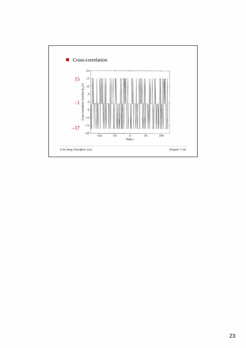
27 − 1 = 127

22
Cross-correlation (of general PN sequences, not necessarily Gold sequences)
© Po-Ning [email protected] Chapter 7-43
Experiment 2: Correlation properties of Gold sequences
© Po-Ning [email protected] Chapter 7-44