chapman sure-set iitm limit switch upgrade · instruction manual pinnacle actuation 298 bell park...
TRANSCRIPT

1
Chapman Sure-Set IITM
Limit Switch Upgrade
Instruction Manual
Pinnacle Actuation 298 Bell Park Drive
Woodstock, GA 30188 770-926-8365
www.pinnacleactuation.com

2
CONTENTS
Product Description Page
General Description 3
Product Installation
Standard Installation 4
Product Operation
Standard Operation
Electrical Startup 8
Manual Operation 9
Switch Setting Operation 9
Product Maintenance
Lubrication 11
Repair and Replacement
Gaskets, Seals 11
Limit Switch Contact Blocks 11
Troubleshooting 11
Parts List 12

3
Product Description
The Pinnacle Actuation Chapman Sure-Set II Limit Switch Upgrade Kit has been engineered to replace
the obsolete Chapman Quick Break Limit Switch assembly. Each upgrade kit consists of a four (4) rotor,
four (4) contact per rotor geared limit switch assembly and the necessary mounting hardware to adapt
the Sure-Set II Limit Switch Assembly to your existing Chapman Valve Operator. Two of the rotors are
used for end-of-travel indication / control and the remaining two rotors may be adjusted for any
intermediate point of travel.
Standard configuration provides for 2 normally open and 2 normally closed contacts per rotor. If
desired, the contact block rotors may be reconfigured individually or in conjunction with adjacent rotors
from normally open to normally closed or visa versa for specific applications.
4
Installation
SAFETY PRECAUTIONS
CAUTION: The geared limit switch is not preset at the factory and must be adjusted after the upgrade
kit is mounted on the associated equipment.
Disconnect all incoming power to the switch assembly prior to opening the limit switch cover
and adjusting the switch.
Consult the relevant wiring diagram for limit switch contact development. All Sure-Set II
Upgrade Kits are supplied with 16-contact limit switches – four switches on each of the four
rotors. Two rotors are used for end-of-travel indication. The remaining two rotors may be
adjusted for any intermediate point-of-travel.
Do not use abrasive cloth to clean the contacts on the limit switch.
Do not attempt to repair gearing in the limit switch. Replace the entire gear frame assembly if
necessary.
CAUTION: When setting the limit switch rotor segments (cams) using a variable speed electric drill, do
not run drill at speeds higher than 200 RPM. Operating the drill at high speeds can damage the
gearing within the limit switch.
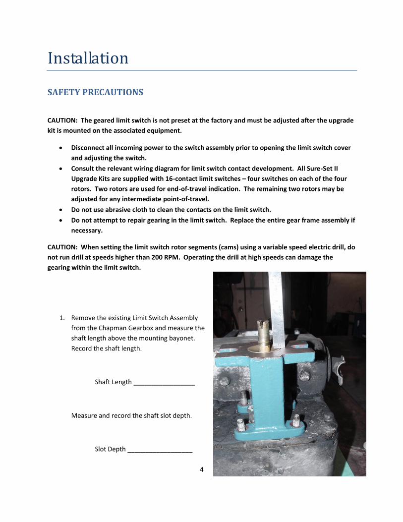
1. Remove the existing Limit Switch Assembly
from the Chapman Gearbox and measure the
shaft length above the mounting bayonet.
Record the shaft length.
Shaft Length _________________
Measure and record the shaft slot depth.
Slot Depth __________________

5
2. Remove the Mounting Bayonet from the
old limit switch assembly. Discard the
old limit switch.
3. Determine the correct shaft extension to
use for this application by measuring the
height of the Mounting Bayonet.
Correct shaft extension will be bayonet
height plus 3/8” to 3/4”.

6
4. Temporarily install the Shaft Extension
onto the Limit Switch Drive Shaft. Install
the bayonet and measure the length of
the shaft above the Mounting Bayonet.
The length must be the same as recorded
in Step 1 above. If the shaft is too long,
cut to the required length.
5. If it was necessary to cut the shaft,
measure the slot depth to ensure that, as
a minimum, the depth is equal to or
greater than the slot depth recorded in
Step 1. If the slot depth is less than the
slot depth recorded in Step 1, increase
the slot depth as required.
6. Secure the shaft extension in place
utilizing the roll pin provided. Remove
and discard the red gag screw from the
front of the switch above the clutch screw.
7. Install the shaft packing and packing
retainer in the bayonet assembly. Install
the Bayonet and Sure-Set II limit switch
assembly on the Chapman Valve
Operator. Ensure there is no binding.
8. Connect the limit switch wiring utilizing
the Contact Arrangement Diagram attached.
9. Adjust the Limit Switch Setpoints in accordance with the Limit Switch Setting Procedure
contained in the Operation section of this manual.

7

8
Operation
WARNING: Do not manually operate the actuator with devices other than
the installed handwheel and shift lever. Using force beyond the ratings of
the actuator and / or using additive force devices such as cheater bars,
wheel wrenches, pipe wrenches or other devices on the actuator
handwheel or shift lever may cause serious personnel injury and / or
damage to the actuator or valve.
CAUTION: Do not motor-operate the valve without first setting or checking the
limit switch setting and motor direction. If the valve closes when the open
button is pushed, the motor may need to be electrically reversed.
Do not force the shift lever into hand or motor position.
Do not alternately start / stop the motor to open or close the valve that is too tight for normal
operation.
Electrical Start-up
1. Verify the actuator has been correctly lubricated
2. Verify the geared limit switch has been correctly set per the Limit Switch Setting Procedure
3. If the valve stem is not visible, remove the stem cover to observe the output direction of the
stem nut assembly.
4. Shift the actuator to the manual mode and hand crank the valve well away from the end-of-
travel positions.
5. Turn on the power supply and push the “open” button on the pushbutton station.
6. Check output rotation:
If phase rotation is correct the valve should begin to open.
If the valve begins to CLOSE, STOP IMMEDIATELY. Incorrect phase rotation will lead to
serious damage if the valve seats.
7. Correct the phase rotation one of two ways:
9
Switch any two of the three power leads for three-phase power, or
Reverse the armature leads for DC power.
The actuator should operate correctly and will be stopped at the end-of-travel positions by torque or
limit switch functions. Premature stopping may be caused by incorrect limit switch or cutout switch
settings or obstructions in the valve.
Manual Operation
The actuator has a handwheel for manual operation. The actuator may be manually operated any time
the motor is de-energized.
Manually operate as follows:
1. Move the shift lever to the hand position and engage the latching pin. This action engages the
handwheel and opens the motor cutout switch.
2. Turn the handwheel in the required direction to place the valve in the desired position.
3. Move the shift lever to the motor position and engage the latching pin. Failure to latch the shift
lever in the motor position may prevent electrical operation of the valve actuator.
Limit Switch Setting
CAUTION: When setting the limit switch rotor segments (cams) using a
variable speed electric drill, do not run drill at speeds higher than 200 RPM.
Operating the drill at high speeds can damage the gearing within the limit
switch.
1. Open and remove the Limit Switch Cover.
2. Place the actuator into manual operation by moving the shift lever to the “hand” position and
engage the latching pin. Use the handwheel to operate the valve in the “open” direction. While
operating the valve, note the rotational direction of the intermediate shaft corresponding to the
rotor or rotors to be set.
3. When the valve is fully open, close it one stem nut revolution to allow for coast of moving parts
or refer to the valve manufacturer setting requirements.
4. Push in the Clutch Screw and turn one quarter turn. The rod will latch in this depressed
position.

10
5. Refer to the applicable wiring diagram for contact development. The limit switch contact is
closed when the rotor is engaged with the plunger. If the rotor to be set has not turned 90
degrees to operate the plunger, turn the intermediate shaft in the same direction as noted in
Step 2 until the rotor clearly trips the switches. This rotor is now set correctly.
6. Before moving the valve, depress and turn the clutch screw one-quarter turn to the spring
released position. Insert a screwdriver into the four intermediate shafts to ensure they will not
move.
NOTE: The cross-slotted shafts A, B, C, and D have been designed for use with a No. 2 Phillips
screwdriver shank chucked into a variable speed reversible electric drill. Do not run drill at
speeds higher than 200 RPM.
CAUTION: Do not operate the valve when the Clutch Screw is in a fully
depressed position. Loss of contact setting will occur and the Clutch Screw
will be damaged.
7. Operate the valve by handwheel to fully “close” position; reverse direction by one turn of the
stem nut to allow for coast of moving parts or refer to the valve manufacturer setting
requirements.
8. Set the other rotors by following Steps 4 through 6 above for each rotor.
11
Maintenance
Lubrication
The Chapman Sure-Set II Limit Switch assembly is permanently lubricated utilizing Exxon Beacon 325
Synthetic Grease. Pinnacle Actuation does not recommend disassembly of the limit switch gearbox for
lubricant inspection.
Gaskets and Seals
The limit switch cover utilizes a reusable low density rubber gasket. Under normal conditions,
this gasket will be reusable for the life of the switch assembly.
The shaft extension packing is manufactured from Duralon 9000 gasket material. Duralon 9000
is a self lubricating packing material that will provide satisfactory service for the life of the
switch assembly,
The limit switch cartridge oil seal and o-ring are primarily used to maintain proper switch
alignment. And will provide satisfactory service for the life of the switch assembly.
Limit Switch Contact Blocks
The Chapman Sure-Set II Limit Switch contact blocks are not field serviceable. In the unlikely event of
failure of a contact block a replacement 8 switch contact block assembly is available.
Troubleshooting
Problem Possible Causes
Geared Limit Switch Fails to Stop Travel A. Damaged Control wiring
B. Motor Reversing Contactor sticking
C. Geared Limit Switch improperly set
D. Intermediate shafts not engaged when clutch rod is
released
E. Drive shaft extension connection roll pin sheered
Unable to Operate Actuator by Motor A. Check motor power and control power circuits for
continuity
B. Motor Reversing Contactor failure
C. Geared Limit Switch Improperly set

12
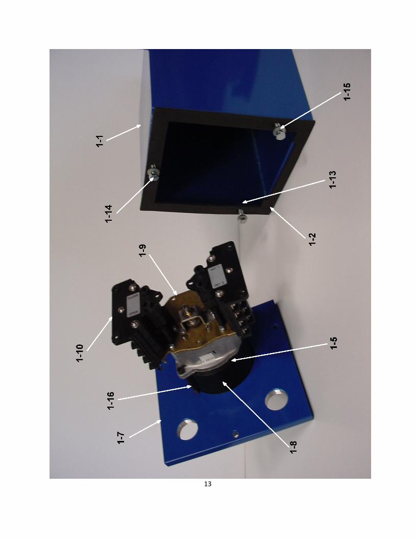
Parts List
Piece Description Quantity Part Number
1-1 Limit Switch Cover 1 888SG
1-2 Limit Switch Cover Gasket, Low Density Rubber 1 7-CHAP-00-A1
1-3 Drive Shaft Extension Packing, Duralon 9000 2 7-CHAP-00-B
1-4 Limit Switch Cartridge Oil Seal 1 7-CHAP-00-F
1-5 Limit Switch Cartridge O-Ring 1 7-CHAP-00-H
1-6 Drive Shaft Extension, 4” 1 7-CHAP-00-D1
1-6 Drive Shaft Extension, 5” 1 7-CHAP-00-D2
1-7 Base Plate 1 7-CHAP-00-C1
1-8 Cartridge Spacer 1 7-CHAP-00-G
1-9 16C Limit Switch Assembly, 4 Gear, Complete 1 7-L20-305-A1
1-10 8 Contact Switch Assembly 2 21800-073
1-11 Stud, Double End, 3/8”-24X1.5 4 11105070
1-12 Roll Pin, 3/32”X1/2” 1 1164055
1-13 Ribbed Nut Insert, ¼”-20 3 0125677
1-14 Hex Cap Screw, ¼”-20X1.25 3 110120305
1-15 Neoprene Washer, 5/8” OD x ¼ 3 35020
1-16 Socket Head Cap Screw, ¼”-20 x 3 2 1123215
13

14