chapter 1: introductionpre-commit phase is added. assume a permanent crash of the coordinator. a...
TRANSCRIPT
Distributed Databases
These slides are a modified version of the slides of the book
“Database System Concepts” (Chapter 20 and 22), 5th Ed.,
McGraw-Hill, by Silberschatz, Korth and Sudarshan.
Original slides are available at www.db-book.com
1.2
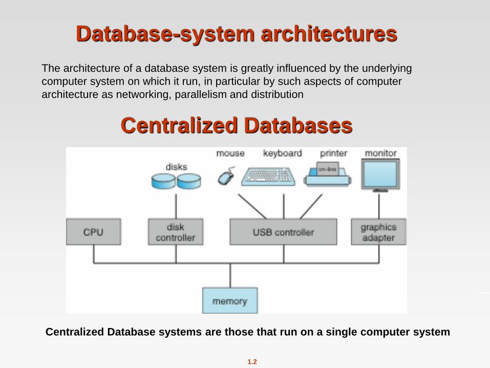
Centralized Databases
Centralized Database systems are those that run on a single computer system
The architecture of a database system is greatly influenced by the underlying
computer system on which it run, in particular by such aspects of computer
architecture as networking, parallelism and distribution
Database-system architectures

1.3
Centralized Systems
Run on a single computer system and do not interact with other
computer systems.
One to a few CPUs and a number of device controllers that are
connected through a common bus that provides access to shared
memory.
Single-user system (e.g., personal computer or workstation): desk-top
unit, single user, usually has only one CPU and one or two hard
disks; the OS may support only one user.
Multi-user system: more disks, more memory, multiple CPUs, and a
multi-user OS. Serve a large number of users who are connected to
the system vie terminals. Often called server systems.
Database-systems support the full transactional features that we have
studied earlier.
1.4
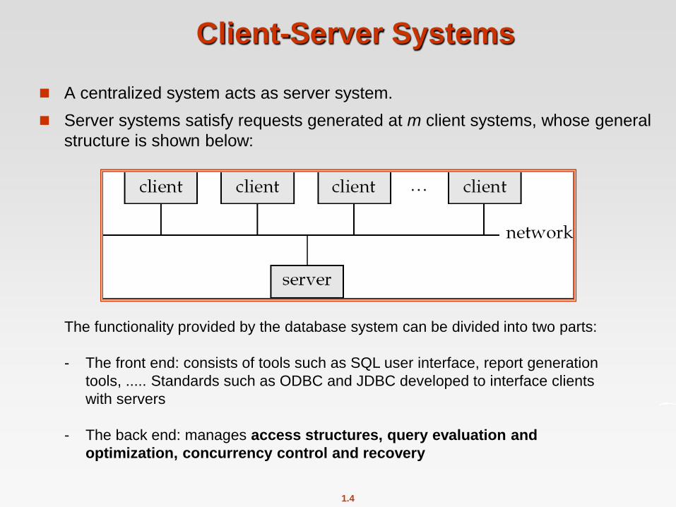
Client-Server Systems
A centralized system acts as server system.
Server systems satisfy requests generated at m client systems, whose general
structure is shown below:
The functionality provided by the database system can be divided into two parts:
- The front end: consists of tools such as SQL user interface, report generation
tools, ..... Standards such as ODBC and JDBC developed to interface clients
with servers
- The back end: manages access structures, query evaluation and
optimization, concurrency control and recovery

1.5
Distributed Databases
Data spread over multiple machines (also referred to as sites or
nodes). Sites do not share main memory or disks.
Network interconnects the machines (LAN or WAN)
Data shared by users on multiple machines
We differentiate between local transactions (access data only from the
site where the transaction was initiated) / global transaction (access
data in a site different from the site where the transaction was initiated
General structure
of a distributed system

1.6
Distributed Databases
Homogeneous distributed databases
Same software/schema on all sites, data may be partitioned among sites (e.g, banking application: data at different branches)
Goal: provide a view of a single database, hiding details of distribution
Heterogeneous distributed databases
Different software/schema on different sites
Goal: integrate existing databases to provide useful functionality

1.7
Trade-offs in Distributed Systems
There are several reasons for building distributed database systems
Sharing data – users at one site able to access the data residing at
some other sites.
Autonomy – each site is able to retain a degree of control over data
stored locally.
Higher system availability through redundancy — data can be
replicated at remote sites, and system can function even if a site fails.
Disadvantage: added complexity required to ensure proper
coordination among sites.
Distributed Databases
1.9
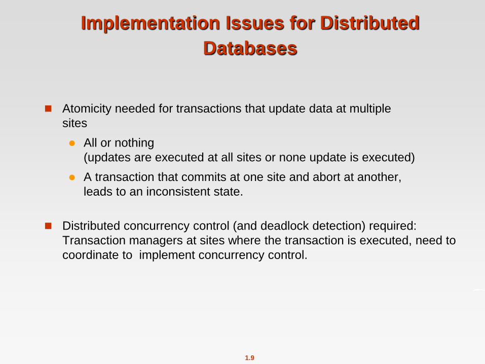
Implementation Issues for Distributed
Databases
Atomicity needed for transactions that update data at multiple
sites
All or nothing
(updates are executed at all sites or none update is executed)
A transaction that commits at one site and abort at another,
leads to an inconsistent state.
Distributed concurrency control (and deadlock detection) required:
Transaction managers at sites where the transaction is executed, need to
coordinate to implement concurrency control.
1.10
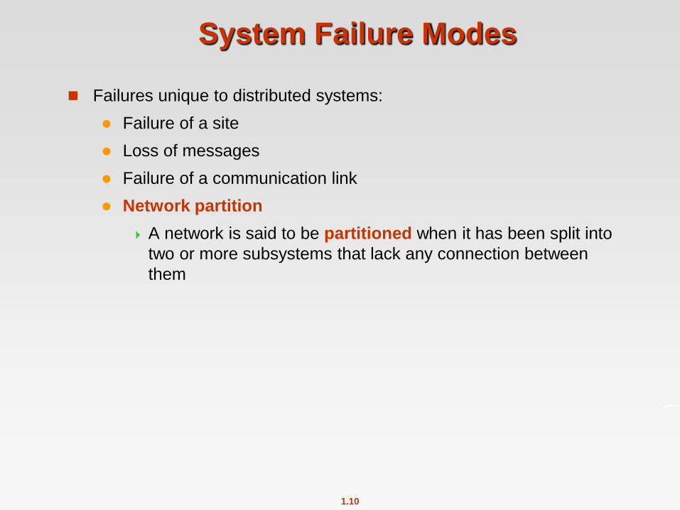
System Failure Modes
Failures unique to distributed systems:
Failure of a site
Loss of messages
Failure of a communication link
Network partition
A network is said to be partitioned when it has been split into
two or more subsystems that lack any connection between
them

1.11
Distributed transactions
t1: begin transaction
UPDATE account
SET balance=balance + 500.000
WHERE account_number=45;
UPDATE account
SET balance=balance - 500.000
WHERE account_number=35;
commit
end transaction
site1 site2
t11: UPDATE account
SET balance=balance + 500.000
WHERE account_number=45;
t12:UPDATE account
SET balance=balance - 500.000
WHERE account number=35;
t1
Client:
t1
t1: distributed transaction
(access data at different sites)
account_number
45
account_number 35
Account =(account_name, branch_name, balance)
divided into a number of fragments, each of which
consists of accounts belonging to a particular branch
Each branch responsable
of data on its accounts
1.12
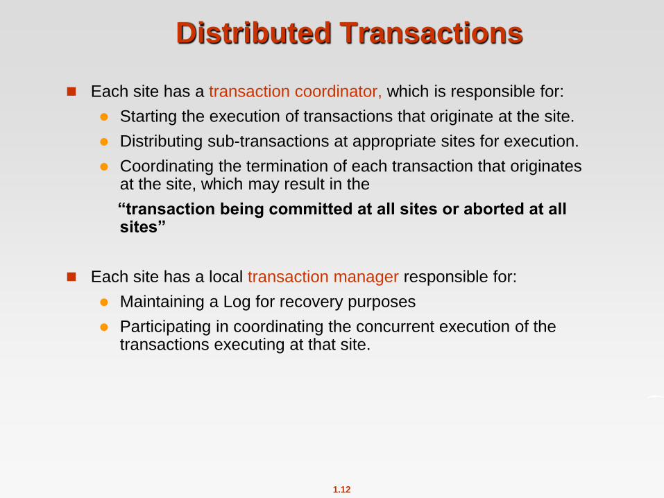
Distributed Transactions
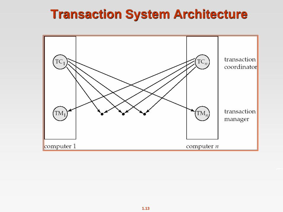
Each site has a transaction coordinator, which is responsible for:
Starting the execution of transactions that originate at the site.
Distributing sub-transactions at appropriate sites for execution.
Coordinating the termination of each transaction that originates at the site, which may result in the
“transaction being committed at all sites or aborted at all sites”
Each site has a local transaction manager responsible for:
Maintaining a Log for recovery purposes
Participating in coordinating the concurrent execution of the transactions executing at that site.
1.13
Transaction System Architecture

1.14
Commit Protocols
Commit protocols are used to ensure atomicity across sites
a transaction which executes at multiple sites must either be
committed at all the sites, or aborted at all the sites.
not acceptable to have a transaction committed at one site and
aborted at another
The two-phase commit (2PC) protocol is widely used
The three-phase commit (3PC) protocol is more complicated and
more expensive, but avoids some drawbacks of two-phase commit
protocol.
The four-phase commit (4PC) avoids some drawbacks by replicating
the transaction coordinator.

1.15
Two Phase Commit Protocol (2PC)
Assumes fail-stop model – failed sites simply stop working, and do
not cause any other harm, such as sending incorrect messages to
other sites.
Execution of the protocol is initiated by the coordinator after the last
step of the transaction has been reached.
The protocol involves all the local sites at which the transaction
executed
Let T be a transaction initiated at site Si, and let the transaction
coordinator at Si be Ci
1.16
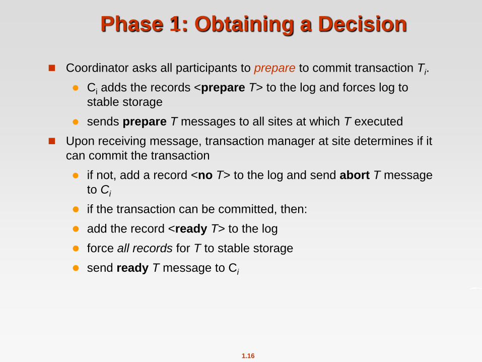
Phase 1: Obtaining a Decision
Coordinator asks all participants to prepare to commit transaction Ti.
Ci adds the records <prepare T> to the log and forces log to
stable storage
sends prepare T messages to all sites at which T executed
Upon receiving message, transaction manager at site determines if it
can commit the transaction
if not, add a record <no T> to the log and send abort T message
to Ci
if the transaction can be committed, then:
add the record <ready T> to the log
force all records for T to stable storage
send ready T message to Ci
1.17
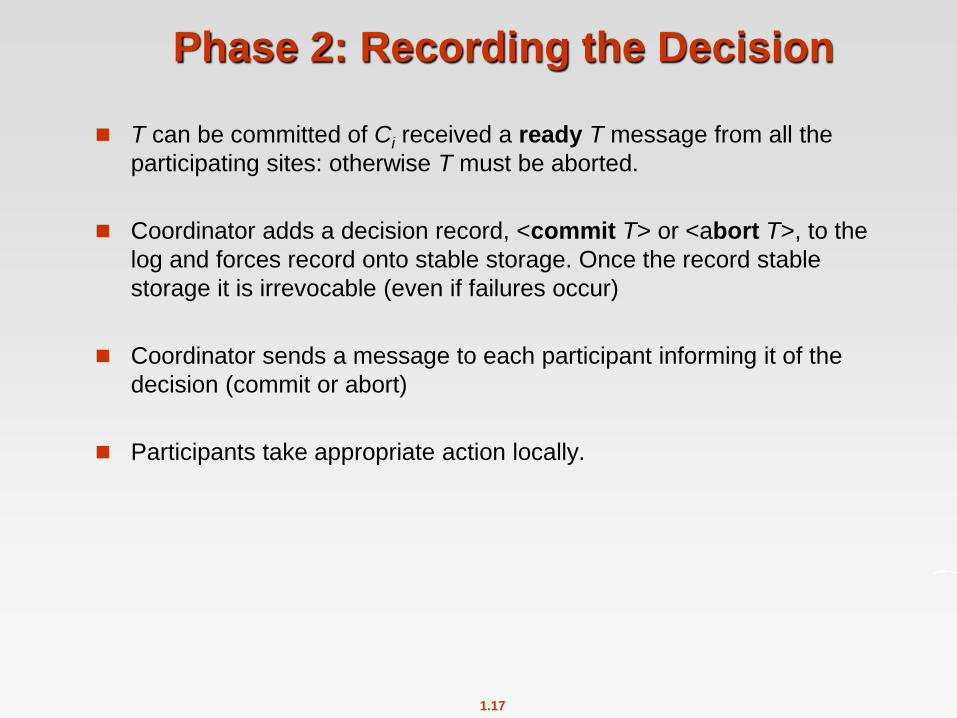
Phase 2: Recording the Decision
T can be committed of Ci received a ready T message from all the
participating sites: otherwise T must be aborted.
Coordinator adds a decision record, <commit T> or <abort T>, to the
log and forces record onto stable storage. Once the record stable
storage it is irrevocable (even if failures occur)
Coordinator sends a message to each participant informing it of the
decision (commit or abort)
Participants take appropriate action locally.
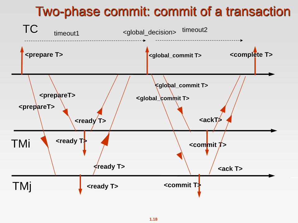
1.18
TC
Two-phase commit: commit of a transaction
TMi
<prepare T> <global_commit T>
<ready T> <commit T>
<prepareT>
<ready T>
<global_commit T>
<complete T>
<ackT>
<commit T> <ready T> TMj
<ready T>
<prepareT>
timeout1 timeout2 <global_decision>
<global_commit T>
<ack T>
1.19
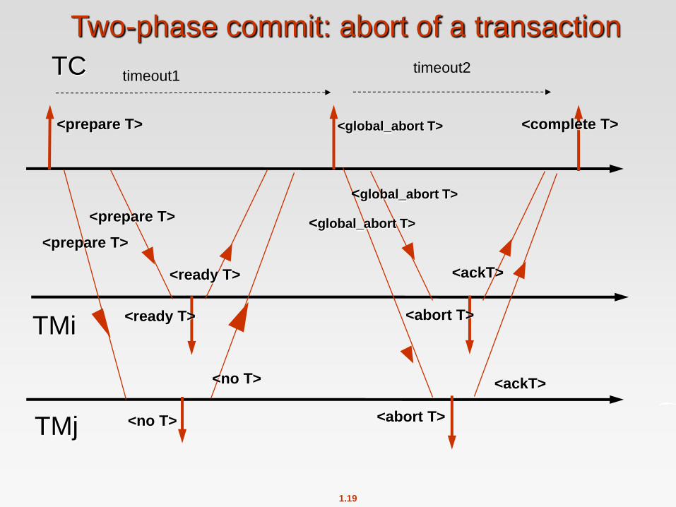
TC
Two-phase commit: abort of a transaction
TMi
<prepare T> <global_abort T>
<ready T> <abort T>
<prepare T>
<ready T>
<global_abort T>
<complete T>
<ackT>
<abort T> <no T> TMj
<no T>
<prepare T>
timeout1 timeout2
<global_abort T>
<ackT>
1.20
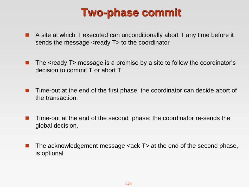
A site at which T executed can unconditionally abort T any time before it
sends the message <ready T> to the coordinator
The <ready T> message is a promise by a site to follow the coordinator’s
decision to commit T or abort T
Time-out at the end of the first phase: the coordinator can decide abort of
the transaction.
Time-out at the end of the second phase: the coordinator re-sends the
global decision.
The acknowledgement message <ack T> at the end of the second phase,
is optional
Two-phase commit
1.21
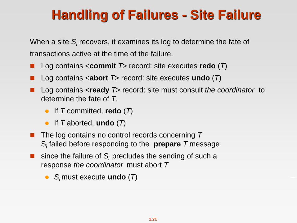
Handling of Failures - Site Failure
When a site Si recovers, it examines its log to determine the fate of
transactions active at the time of the failure.
Log contains <commit T> record: site executes redo (T)
Log contains <abort T> record: site executes undo (T)
Log contains <ready T> record: site must consult the coordinator to
determine the fate of T.
If T committed, redo (T)
If T aborted, undo (T)
The log contains no control records concerning T
Si failed before responding to the prepare T message
since the failure of Si precludes the sending of such a
response the coordinator must abort T
Si must execute undo (T)

1.22
Handling of Failures- Coordinator Failure
When coordinator Ci recovers, it examines its log:
Log contains < prepare T> record:
T is aborted or the prepare message is re-sent
Log contains <global_decision> record: global decision is re-sent
Blocking problem : active sites may have to wait for failed
coordinator to recover.
If a site has a <ready T> record in its logs, but no additional control
records (such as <abort T> of <commit T>), the site must wait for Ci
to recover, to find decision.
A participant can’t assume the role of the coordinator to terminate the
transaction

1.23
Handling of Failures - Network Partition
If the coordinator and all its participants remain in one partition, the
failure has no effect on the commit protocol.
If the coordinator and its participants belong to several partitions:
Sites that are not in the partition containing the coordinator think
the coordinator has failed, and execute the protocol to deal with
failure of the coordinator.
No harm results, but sites may still have to wait for decision
from coordinator.
The coordinator and the sites are in the same partition as the
coordinator think that the sites in the other partition have failed, and
follow the usual commit protocol.
Again, no harm results
1.24
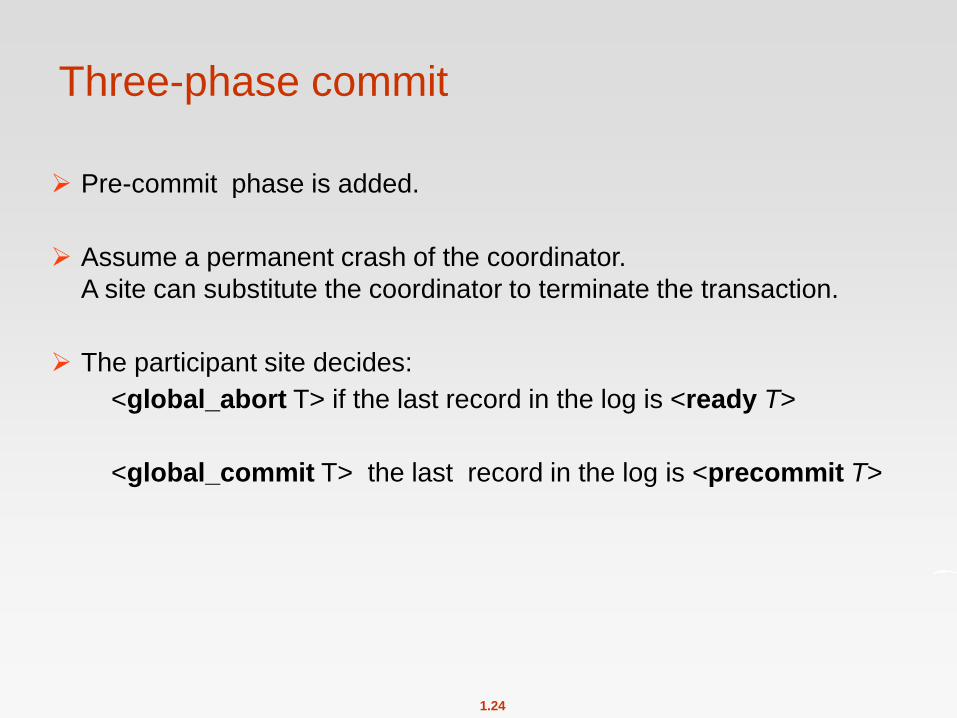
Three-phase commit
Pre-commit phase is added.
Assume a permanent crash of the coordinator.
A site can substitute the coordinator to terminate the transaction.
The participant site decides:
<global_abort T> if the last record in the log is <ready T>
<global_commit T> the last record in the log is <precommit T>
1.25
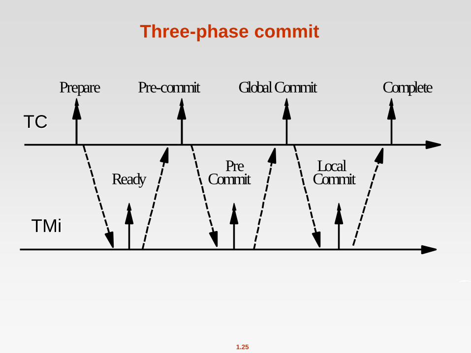
Three-phase commit
Prepare CompletePre-commit Global Commit
LocalCommit
PreCommitReady
TC
TMi
1.26
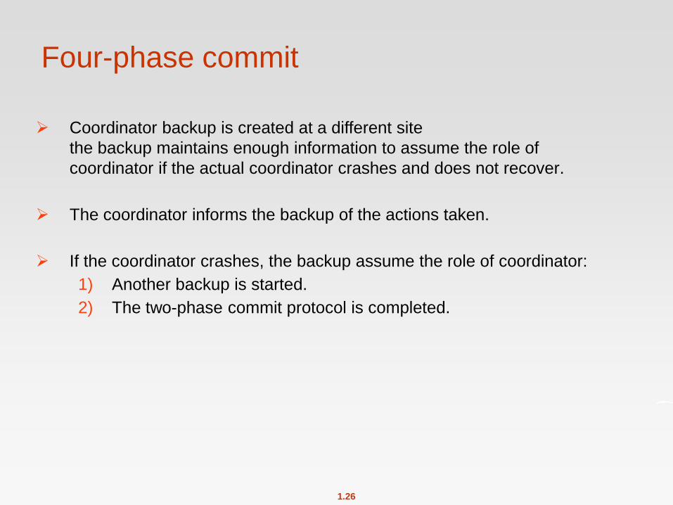
Four-phase commit
Coordinator backup is created at a different site
the backup maintains enough information to assume the role of
coordinator if the actual coordinator crashes and does not recover.
The coordinator informs the backup of the actions taken.
If the coordinator crashes, the backup assume the role of coordinator:
1) Another backup is started.
2) The two-phase commit protocol is completed.
1.27
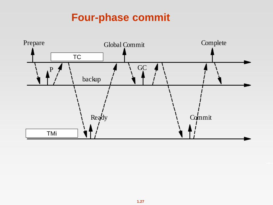
Four-phase commit
P GC
Global Commit CompletePrepare
Ready Commit
partecipante (RM)
coordinatore (TM)
backup
TC
TMi
1.28
Atomicity property
We assume that each site participates in the execution of a commit
protocol to ensure global transaction automicity.

1.29
Concurrency Control
Modify concurrency control schemes for use in distributed environment.
Given a distributed transaction ti, we use the following notation:
tij: sub-transaction of ti executed at site j
rij(x): ti executes read(x) at site j
wij(x): ti executes write(x) at site j
1.30
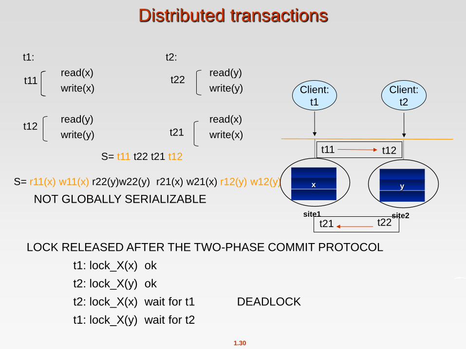
t1: t2:
read(x) read(y)
write(x) write(y)
read(y) read(x)
write(y) write(x)
S= t11 t22 t21 t12
S= r11(x) w11(x) r22(y)w22(y) r21(x) w21(x) r12(y) w12(y)
NOT GLOBALLY SERIALIZABLE
site1
x
site2
y
Client:
t1
Client:
t2
t11 t12
t22 t21
Distributed transactions
t11
t12
t22
t21
LOCK RELEASED AFTER THE TWO-PHASE COMMIT PROTOCOL
t1: lock_X(x) ok
t2: lock_X(y) ok
t2: lock_X(x) wait for t1 DEADLOCK
t1: lock_X(y) wait for t2
1.31
site1 site2
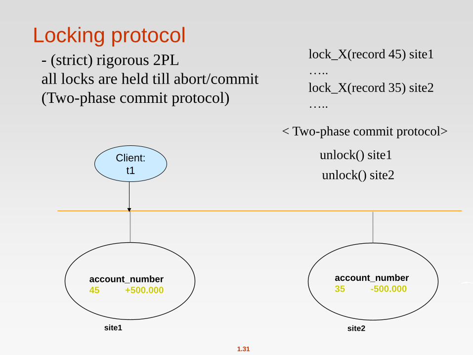
Locking protocol - (strict) rigorous 2PL
all locks are held till abort/commit
(Two-phase commit protocol)
lock_X(record 45) site1
…..
lock_X(record 35) site2
…..
unlock() site1
unlock() site2
< Two-phase commit protocol>
Client:
t1
account_number
45 +500.000
account_number
35 -500.000
1.32
Single-Lock-Manager Approach
System maintains a single lock manager that resides in a single
chosen site, say Si
When a transaction needs to lock a data item, it sends a lock request
to Si and lock manager determines whether the lock can be granted
immediately
If yes, lock manager sends a message to the site which initiated
the request
If no, request is delayed until it can be granted, at which time a
message is sent to the initiating site

1.33
Single-Lock-Manager Approach (Cont.)
Advantages of scheme:
Simple implementation
Simple deadlock handling
Disadvantages of scheme are:
Bottleneck: lock manager site becomes a bottleneck
Vulnerability: system is vulnerable to lock manager site failure.
t1 t2
y
x
Wait-for graph
(cycle) site1
x
site2
y
Client:
t1
Client:
t2
t11 t12
t22 t21
1.34
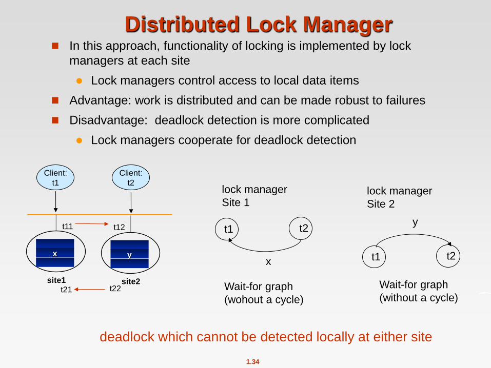
Distributed Lock Manager In this approach, functionality of locking is implemented by lock
managers at each site
Lock managers control access to local data items
Advantage: work is distributed and can be made robust to failures
Disadvantage: deadlock detection is more complicated
Lock managers cooperate for deadlock detection
t1 t2
y
Wait-for graph
(without a cycle)
t1 t2
x
Wait-for graph
(wohout a cycle)
lock manager
Site 1 lock manager
Site 2
site1
x
site2
y
Client:
t1
Client:
t2
t11 t12
t22 t21
deadlock which cannot be detected locally at either site

1.35
Timestamping
Timestamp based concurrency-control protocols can be used in
distributed systems
Each transaction must be given a unique timestamp
Main problem: how to generate a timestamp in a distributed fashion
Each site generates a unique local timestamp using either a logical
counter or the local clock.
Global unique timestamp is obtained by concatenating the unique
local timestamp with the unique identifier.

1.36
site2
site3
site1 1.1 7.1 2.1 8.1
5.3 6.3
1.2 2.2
7.3
Lamport algoritm to assign timestamps
Timestamp: local_timestamp.site_identifier
(integer)
1.37
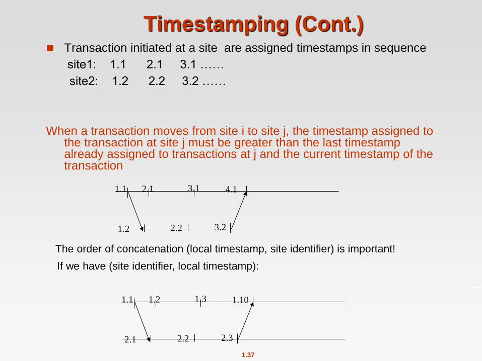
Timestamping (Cont.) Transaction initiated at a site are assigned timestamps in sequence
site1: 1.1 2.1 3.1 ……
site2: 1.2 2.2 3.2 ……
When a transaction moves from site i to site j, the timestamp assigned to the transaction at site j must be greater than the last timestamp already assigned to transactions at j and the current timestamp of the transaction
1.1 2.1 3.1
1.2 2.2 3.2
4.1
The order of concatenation (local timestamp, site identifier) is important!
1.1 1.2 1.3
2.1 2.2 2.3
1.10
If we have (site identifier, local timestamp):
1.38
Deadlock detection locally at each site is not sufficient
Distributed Lock Manager:
Handling deadlock
1.39
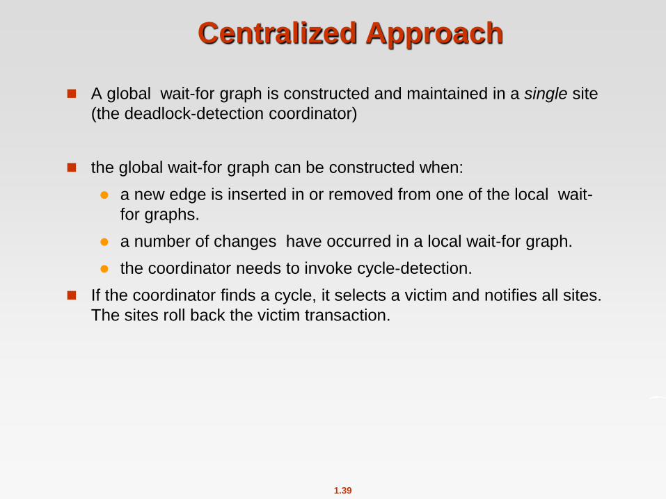
Centralized Approach
A global wait-for graph is constructed and maintained in a single site
(the deadlock-detection coordinator)
the global wait-for graph can be constructed when:
a new edge is inserted in or removed from one of the local wait-
for graphs.
a number of changes have occurred in a local wait-for graph.
the coordinator needs to invoke cycle-detection.
If the coordinator finds a cycle, it selects a victim and notifies all sites.
The sites roll back the victim transaction.

1.40
Distributed deadlock detection algorithm
(IBM DB2)
- A transaction is divided into sub-transactions executing at different sites
- Sub-transactions are executed synchronously
t11 enables t12
t11 waits for the completion of t12
Waiting conditions:
1) A sub-transaction of t waits for another sub-stransaction of t
executed at a different site
2) A sub-transaction of t waits for a sub-transaction of t’
on a shared data item x

1.41
site 1
DBMS 1
site 2
DBMS 2
t12: lock_X(y)
waits t22
t11 enables t12
t11 waits t12
t22 enables t21
t22 waits t21
t12
t11
lock_X(x)
t21
t22
lock(y)
x y
t1: r11(x) w11(x) r12(y) w12(y)
t2: r22(y)w22(y) r21(x) w21(x)
S = r11(x) w11(x) r22(y)w22(y) r21(x) w21(x) r12(y) w12(y)
Distributed deadlock detection algorithm
(IBM DB2)
t21: lock_X(x)
waits t11

1.42
- Wait-for sequences
Ein -> ti -> tj -> Eout
Example:
DBMS1: E2 -> t21 -> t11 -> E2
DBMS2: E1 -> t12 -> t22 -> E1
- Build the wait-for graph locally to a site
Distributed deadlock detection algorithm
(IBM DB2)

1.43
Each site periodically runs the algorithm:
Phase 1
- update the wait-for graph locally with received “wait-for sequences”
Phase 2
- check the wait-for graph locally: if a deadlock arises, rollback
a selected transaction. Abort of the transaction at all sites
Phase 3
- “wait-for sequences” are computed and sent to other sites
Distributed deadlock detection algorithm
The same deadlock can be deteced at multiple sites.
Different transactions can be chosen for the rollback at sites.

1.44
Ein -> ti -> tj -> Eout
- a wait-for sequence is sent iff :
i > j, with i and j the transaction identifiers
- Sequences are sent forward, i.e., to the DBMS where
transaction tj is executed
Distributed deadlock detection algorithm
RULE:
1.45
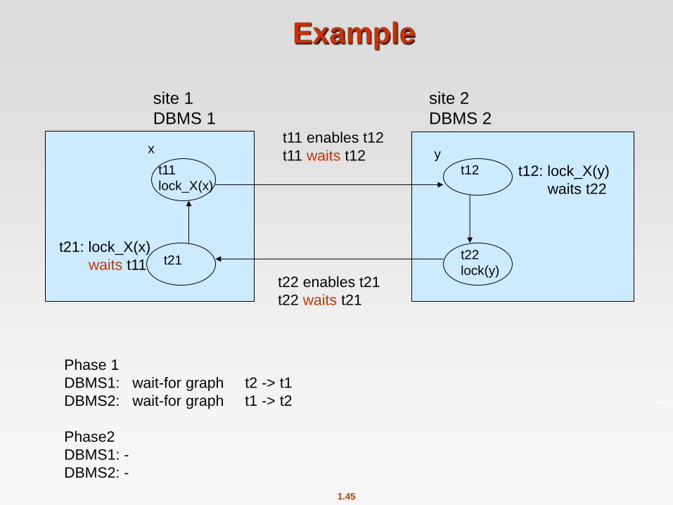
Example
site 1
DBMS 1
site 2
DBMS 2
t12: lock_X(y)
waits t22
t11 enables t12
t11 waits t12
t22 enables t21
t22 waits t21
t12
t11
lock_X(x)
t21
t22
lock(y)
x y
t21: lock_X(x)
waits t11
Phase 1
DBMS1: wait-for graph t2 -> t1
DBMS2: wait-for graph t1 -> t2
Phase2
DBMS1: -
DBMS2: -
1.46
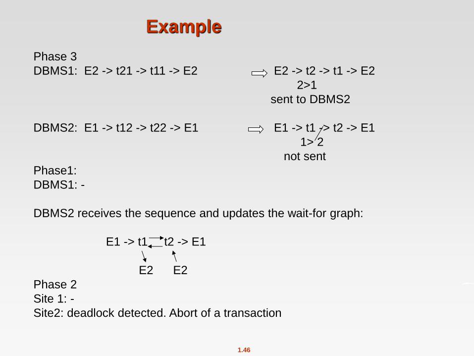
Phase 3
DBMS1: E2 -> t21 -> t11 -> E2 E2 -> t2 -> t1 -> E2
2>1
sent to DBMS2
DBMS2: E1 -> t12 -> t22 -> E1 E1 -> t1 -> t2 -> E1
1> 2
not sent
Phase1:
DBMS1: -
DBMS2 receives the sequence and updates the wait-for graph:
E1 -> t1 t2 -> E1
E2 E2
Phase 2
Site 1: -
Site2: deadlock detected. Abort of a transaction
Example
1.47
Distributed Query Processing
For centralized systems, the primary criterion for measuring the cost
of a particular strategy is the number of disk accesses.
In a distributed system, other issues must be taken into account:
The cost of a data transmission over the network.
The potential gain in performance from having several sites
process parts of the query in parallel.