chapter-14 final aerobic-digestion
DESCRIPTION
yesTRANSCRIPT

14-1 Chapter 14_Final_Aerobic Digestion_.docx
Chapter 14
Aerobic Digestion 14.1 Existing Conditions The aerobic sludge holding/storage tanks or digesters store sludge wasted from the bottom of the primary and secondary clarifiers. The digesters also provide stabilization of the waste sludge, reducing the volatile suspended solids and pathogen levels. The greater the digester capacity the more stable the biosolids fed to the downstream dewatering and drying processes will be. Digester capacity generally depends on the level of thickening achieved. Clarified liquid can be decanted from a digester tank as supernatant to allow for solids thickening and to increase solids storage time. Supernatant removal is provided by telescopic valves. Supernatant from each draw-off discharges into Manhole 101 and from there to the plant drain pump station before it is returned to the primary clarifier distribution box. After digestion, the sludge is dewatered in the belt filter presses (BFPs).
There are a total of five sludge storage tanks at the Salisbury WWTP. Tanks 1 through 3 are circular and they used to be part of an older anaerobic digestion system originally installed in the 1950’s. Tank 4 is rectangular and was constructed as part of the BNR/ENR expansion. Also as part of the BNR/ENR expansion, Tank 3 was divided into two sections, of which, according to record drawing and O&M manual information, Tank 3A was designed to receive secondary sludge and Tank 3B a mixture of primary and secondary sludge. Tank 3B is currently the only tank that can feed the BFPs. It must be noted here that the existing SCADA system has these two tank names reversed. Plant operators currently use the SCADA naming convention. Sludge from every tank has to be transferred by pumping to Tank 3B and from there to the BFPs for dewatering. Dimensions and volumes of the sludge storage tanks are provided in Table 14-1. The approximate effective volume of Tanks 3A and 3B is 294,000 and 92,000 gallons, respectively.
The original design called for three tanks to be used for secondary sludge storage (Tanks 2, 3A, and 4) and Tank 1 for primary sludge storage. In general, it is very difficult to keep primary sludge aerobic. Primary sludge requires a significant air supply to remain mixed and aerobic and that was witnessed during our November 20, 2009 site visit, when intermittent aeration of primary sludge created odors and a layer of floating material on top of Tank 1. The sooner primary sludge turns aerobic the better in terms of reducing odors and stabilizing the sludge prior to dewatering and drying. Mixing of primary with secondary sludge, though it does not solve the nuisance issues associated with aerating raw sludge, is preferred over aerating pure primary sludge. Currently, secondary sludge is pumped to Tank 2 where it overflows through the supernatant draw-off system into the drainage system, then to the plant drain pump station and from there be diverted to the primary clarifier splitter box for co-settling and co-thickening with the primary sludge in the primary clarifiers. This arrangement is necessary because the ability to return secondary sludge directly to the head of the plant was eliminated in the BNR/ENR upgrade. Given this mode of operation, Tanks 1, 3A, and 4 theoretically receive and store co-settled primary and secondary sludge collected from the underflow of the primary clarifiers.

Salisbury Wastewater Treatment Plant PER Chapter 14
14-2
Chapter 14_Final_Aerobic Digestion_.docx
Table 14-1. Aerated Sludge Holding Tanks
Tank 1 - Digester Tank (1958) Value
Inside Diameter (ft) 55
Side Wall Depth (ft) 22
Side Water Depth (ft) 20.5
Center Depth (ft) 29
Center Water Depth (ft) 27.5
Approximate Effective Volume (gal) 400,000
Tanks 2 and 3 - Digester Tanks (1952) Value
Inside Diameter (ft) 60
Side Wall Depth (ft) 18
Side Water Depth (ft) 16.5
Center Depth (ft) 25
Center Water Depth (ft) 23.5
Approximate Effective Volume per Tank (gal) 400,000
Tank 4 Value
Approximate Effective Volume (gal) 250,000
Total Approximate Effective Volume (gal) 1,450,000
The sludge holding tanks are mixed by a coarse bubble aeration system using positive displacement blowers (Table 14-2). Non-condensable off-gas from the dryer is also bubbled into Tanks 1 and 2 as a means to mitigate any odors. The total sludge holding volume is 1,450,000 gallons and the four available blowers were sized to deliver a maximum of 1650 scfm each or 6,600 scfm combined. This corresponds to 6,226 lb of oxygen per day per blower or 24,905 lb of oxygen per day in total, under standard conditions and assuming a 15% standard oxygen transfer efficiency (SOTE used by Sanitaire). The air supply to the aerobic digesters is properly sized as documented by the following calculation checks that show that all three aerobic digestion aeration sizing criteria are satisfied:
1. The supplied air divided by the total sludge volume equals 34 scfm/1,000 cf, which exceeds the minimum of 30 cfm per 1,000 cf of sludge volume recommended in the 10-state standards (2004) and in the 1978 MDE guidelines. Individually, considering the largest tank (400,000 gallons) with its dedicated blower aerating it, the mixing input is approximately 31 scfm/1,000 cf of sludge volume, which is still over the minimum recommended guideline.
2. Air demand is dictated by the biological oxygen demand (BOD) in primary sludge, which is 1.6 to 1.9 lb of oxygen per lb of BOD destroyed for mixed sludges (Metcalf & Eddy, 2003, p. 1538). The average BOD loading in the raw influent at 8.5 MGD plant flows was estimated at 20,600 lb/d. This means that there is sufficient air in the aerated sludge holding tanks to theoretically destroy the entire BOD loading resulting from a primary clarification process that removes more than 63% of the BOD found in its influent (24,900/1.9/ 20,600).
3. The mass rate ratio of oxygen provided (24,900 lb/d) to VS after decant (15,200 lb/d) equates to approximately 1.6 lb of oxygen per lb of cell tissue (VS). The standard minimum oxygen demand for biological stabilization reported in WEF’s MOP-8 (p. 25-158) is 2.0 parts of oxygen per part of organic cell mass destroyed. To that, another 1.6 to 1.9 parts for a total of 3.6 to 3.9 parts of oxygen per part of volatile solids destroyed have to be added to account for primary solids addition. This suggests

Salisbury Wastewater Treatment Plant PER Chapter 14
14-3
Chapter 14_Final_Aerobic Digestion_.docx
that, in theory, there is enough oxygen to destroy approximately 41 – 44 % of the VS that remain in the tanks after decant. If the VS content of the raw sludge before decant (25,500 x 70% = 17,850 lb/d) is used instead, the supplied oxygen drops to 1.4 lb per lb of cell tissue and the theoretical VS destruction drops to a range of 36 – 39 %. Aerobic digestion is not sized for complete oxidation and a 38% VS reduction is often a satisfactory minimum. Based on the above this criterion is also met by the existing aeration system. However performance of the system will be limited by the time the constituents are exposed to the air supplied or, in other words, by its SRT. Its is expected that, in the future, as plant flows and sludge production rates increase, the plant will not be able to stabilize the sludge well in winter.
Table 14-2. Aerated Sludge Holding Equipment
Transfer and BFP Feed Pumps Value Units
Manufacturer Seepex
Units 5
Range BN
Model/Size 130
Pressure 6L
Conveying Capacity (Min, Nominal, Max) 150, 337, 400 gpm
Pump Speed 78, 176, 209 rpm
Motor 30 HP
Blowers
Manufacturer United Blower
Units 4
Model/Size RAM 616
Load 110P
Capacity 1650 scfm
Motor 125 HP
14.2 Corrective Action Plan Several different alternatives were discussed in the June 2010 CAP, including optimizing the existing process or resorting back to anaerobic digestion for sludge stabilization. Because the capital costs to convert the stabilization process from aerobic back to anaerobic are significant and fixing the liquid treatment process train is currently a priority, this upgrade will only include limited modifications to the existing system to optimize the aerobic digestion process, minimize odors, and produce a more stable feedstock to the downstream sludge drying process. This will be accomplished by creating two trains of two tanks connected in series and covering the first tanks of each train to control the odors from the fresh raw sludge. Foul air will be diverted to a new odor control system. A sludge grinder will be installed upstream of the pumps that currently feed the BFPs.

Salisbury Wastewater Treatment Plant PER Chapter 14
14-4
Chapter 14_Final_Aerobic Digestion_.docx
14.3 Basis of Design As part of the proposed upgrades, Tank 1 will be connected with Tank 4 and Tank 2 with Tank 3A via gravity lines as shown in Figures 14-1 and 14-2. Tanks 1 and 2, the first tanks of each train, will be covered with flat aluminum covers to contain the malodors emitted by the fresh raw sludge they will be receiving. The off-gas from both tanks will be diverted to a new odor control system consisting of a biotrickling filter followed by a biofilter as shown in Figures 14-1 and 14-3. The odor control system will be sized to handle 6400 scfm air flow received from both Tanks 1 and 2 combined. A breakout of the total air flow is as follows: (1) 1650 scfm of maximum process air per tank, (2) 1300 scfm of leakage per tank (0.5 scfm per sf of cover) and (3) 500 scfm of condenser gas flow from the dryer, divided by two for each tank.
When a train is ready to be dewatered, each tank will be pumped to Tank 3B one at a time and from there to the BFPs as currently performed. Provisions to transfer sludge from any tank to Tank 3B by pumping will remain unchanged. Sludge pumping and dewatering should be protected as follows. As part of this project, comminutors at the raw influent PSs will be installed to protect the downstream raw influent pumps. Comminutors will be grinding rags and debris, part of which will then flow through the screens into the plant. The potential therefore exists for small pieces of rags that escape preliminary treatment to re-agglomerate somewhere downstream and create operational problems with piping and valves, especially in the solids treatment train. A grinder, typically installed upstream of sludge pumps and expensive process equipment, would regrind any re-agglomerated rags that would otherwise create issues. A grinder is proposed at the common 6-inch suction manifold upstream of the progressing cavity pumps that feed the BFPs. That way both feed pumps, the mixing valves, and the BFPs will be protected.
As part of this project, all four aerobic digestion tanks should become available to store and aerate sludge. This will require discontinuing the use of Tank 2 as secondary sludge drain and making the appropriate piping modifications to be able to pump WAS back to the primary clarifier (PC) splitter box for co-settling with the primary sludge (PS) in the PCs. As an alternate option, if WAS is to be mixed with PS in the pipe feeding the aerobic digesters, WAS pumping should be sized appropriately not to be negatively affected by the PS pumping using progressing cavity pumps. Ideally, positive displacement pumps should be used for WAS pumping as currently done for PS pumping. The benefit of sending WAS back to the primary clarifiers is the theoretical pre-thickening of the sludge mixture accomplished at the primary clarifiers resulting in a reduced number of decants needed at the downstream aerobic digesters. However, it is still unclear whether the primary clarifiers can thicken the sludge to a 1.5% to 2% solids content range that is needed for an efficient dewatering operation without raising the sludge blankets to excessively high levels.
We also propose to install rotary drum thickeners (RDTs) to provide an alternative method of thickening the WAS that will prevent impacts to the operation of the primary clarifiers. During high flow events, sludge bulking events, or warm summer weather, it may be beneficial to thicken the WAS using the RDTs rather than co-thickening in the primary clarifiers. The RDTs will be mounted on the roof of the digester complex and discharge into the top of the first aerobic digester in each train. Each RDT will be sized to handle a flow of 250-275 gprm to allow both WAS or MLSS to be pumped to them for thickening.
The targeted thickened secondary sludge concentration should be approximately 3.0 percent in solids. Thickened secondary sludge will directly discharge into Tank 1 or 2 where it will be mixed with primary sludge. To avoid oxygen transfer limitations and autothermal thermophilic digestion, the mixture of primary and thickened secondary sludge should not exceed 2.5 – 3.0 percent in solids. Salisbury WWTP used to operate rotary drum thickeners ahead of an anaerobic digestion process and operators are familiar with this process.


Salisbury Wastewater Treatment Plant PER Chapter 14
14-8
Chapter 14_Final_Aerobic Digestion_.docx
Table 14-3 summarizes the expected performance of the aerobic digestion process considering the available capacity of the existing tanks as well as current and projected raw sludge production rates. Our assumption of a design raw solids production equal to 3,000 pounds per million gallons of plant flow is based on historical data (see CAP) and simulation modeling.
Table 14-3. Mass Balances Across Aerobic Digestion as a Function of Plant Flow and Liquid Treatment Alternative
Parameter Current Fixed Film Current
Suspended Growth Design
Suspended Growth Units
Plant flow (MGD) 5.5 5.5 8.5 MGD
BC assumes a sludge production of 1,000 3,000 3,000
Total solids based on design flow 5,500 16,500 25,500 lb/d
Available solids after decant 4,700 14,000 21,700 lb/d
Volatile solids 3,300 9,800 15,100 lb/d
VSD destroyed 1,300 1,500 1,500 lb/d
Digested solids 3,400 12,600 20,200 lb/d
Solids in decant 825 2,475 3,825 lb/d
Primary sludge 1.3% 1.3% 1.3%
Thickened/Digested solids 1.7% 1.7% 1.7%
% Solids capture from decant 85% 85% 85%
% VS 70% 70% 70%
% VSD 40% 15% 10%
Raw sludge flowrate - average 51,000 152,000 235,000 gpd
Digested solids flowrate after decant 24,000 89,000 142,000 gpd
Decant flowrate 27,000 64,000 93,000 gpd
Detention time in digestion for Class B 42 42 42 days
Detention time available 61.1 16.4 10.2 days
Digestion volume needed for Class B 997,000 3,718,000 5,985,000 gallons
Digestion volume available 1,450,000 1,450,000 1,450,000 gallons
Digestion volume missing NA 2,268,000 4,535,000 gallons
Digestion volume missing NA 303,000 606,000 ft3
Table 14-3 shows results based on a 1.3% solids concentration in the raw sludge and further thickening through decanting at the aerobic digesters to achieve a 1.7% solids concentration in the sludge, which is the minimum sludge thickness needed for an efficient operation of the downstream belt filter press dewatering. The ratio of raw primary to secondary sludge fed to the aerobic digesters is expected to be approximately 70%:30% by weight. This means that the raw sludge breakout will be 18,000 lb/d primary and 8,000 lb/d secondary solids. Even if primary and secondary sludge were conveyed to the solids treatment train separately, the dry solids quantities reported would remain approximately the same. However, the overall thickness of the raw sludge will reduce significantly, mainly due to the thinness of the secondary sludge, resulting in a corresponding increase in sludge volume that will have to be

Salisbury Wastewater Treatment Plant PER Chapter 14
14-9
Chapter 14_Final_Aerobic Digestion_.docx
addressed by more aggressive decanting at the aerobic digesters. In that case, the ratio of raw primary to secondary sludge fed to the aerobic digesters is expected to be approximately 40%:60% by volume.
Assuming that all four main tanks are available to receive sludge and the necessary decanting is performed, the process SRT will be as high as 61 days under current plant flows and treatment conditions. Under current flows, but utilizing a suspended growth biological treatment process the anticipated SRT will drop to approximately 16 days. Under design flow conditions of 8.5 MGD, a 10-day SRT is expected. As a result of the varying SRT, the expected VSD will decrease from the current 40% of a fixed film system to the future 10% of a suspended growth system at design flows.
It must be noted here that, with the existing infrastructure, all four tanks available, and under current sludge production rates, there is sufficient tank capacity to meet Class B stabilization standards by following a batch and rotational operation of the aerobic digestion tanks. Class B standards could be met without any significant testing required, if the digestion SRT is greater than 42 days. The protocol to accomplish this was originally presented in Appendix F of the June 2010 CAP. Until the proposed modifications are complete, following the proposed protocol of CAP’s Appendix F will allow the operators to produce a stable feedstock for the downstream BFPs and dryer; regardless whether the necessary documentation is submitted to the State to formally produce Class B liquid sludge. Once the biological process is converted to suspended growth, the existing capacity will be sufficient to meet quality criteria for drying only, but not Class B standards. According to Fenton, the manufacturer of a candidate replacement sludge dryer, SRTs of less than 16 days will usually produce biosolids of poorer quality. Also, according to the 1978 MDE Design Guidelines for Sewerage Facilities, a minimum 15-day detention time is required for mesophilic aerobic digestion. As future flows increase, the minimum 15-day SRT will not be met and the process will become just sludge holding rather than digestion.
Incorporating the 100,000-gallon equalization basin located adjacent to Tank 4 and further thickening to 2.5% solids, either by persistent decanting or by other means, will allow meeting an SRT of almost 16 days at 8.5 MGD. Proposed construction to incorporate the EQ Tank into Tank 4 is shown in Figure 14-4. Proposed construction will include saw cutting (top and bottom) the common wall of the two tanks to create the interconnect and adding a dropleg connected to a coarse bubble diffuser grid that will also be supplied by the dedicated Sludge Storage Blower 4 located inside the room adjacent to Tank 4. The existing Sludge Storage Blower 4 was originally oversized given the air demand of Tank 4 and has sufficient capacity to supply air to Tank 4 and the new segment that is proposed to be incorporated into Tank 4. The existing sludge discharge piping into Tank 4 shall be relocated to the new section added, so that sludge is forced to flow from the new section to the old before it is decanted or transferred to Tank 3B.


Salisbury Wastewater Treatment Plant PER Chapter 14
14-11
Chapter 14_Final_Aerobic Digestion_.docx
14.4 Process Control Description The June 2010 CAP included three standard operating procedures (SOPs) that were developed to allow maximizing the sludge holding time for sludge stabilization in the existing aerobic digesters prior to dewatering and drying. The three SOPs were develop to address (1) immediate needs at current flows with only three tanks available, (2) intermediate-term needs assuming minor piping modifications with all four tanks available, and (3) long-term needs with all four tanks available.
Of the three, the long-term alternative will be the basis of this design and will include a system where the first two tanks (Tanks 1 and 2) will be continuously mixed and covered for odor control while the last tanks (Tanks 4 and 3A) in the series will be uncovered and allowed to be decanted for partial thickening as shown in the overall flow diagram for solids of Figure 14-1. Figure 14-2 depicts a more detailed process flow diagram with the proposed piping modifications noted to accomplish conversion of the existing system to a two train system. The 8” decant pipeline of the first tank will be connected with the feed pipeline of the second tank with the necessary valves added. The telescoping valve at each first tank will always be at its lowest, completely open position or removed altogether so simultaneous decanting of both tanks in series will be accomplished by exercising the telescoping valve of the second tank. The range of operation of the existing telescoping valves is 3.5 feet.
Table 14-4 shows the sequence of operation (approximate timing and status of tanks) for a couple of digestion cycles under the proposed operational mode at sludge production rates corresponding to a 4-stage Bardenpho system at 5.5 MGD plant flows. Starting with Tanks 1 and 4 empty (Train A) and ready to be filled and Tanks 2 and 3A full (Train B) and ready to be dewatered, each train will undergo a 16-day cycle that will include the following sub-cycles: 1. Five days to completely fill the empty tanks of Train A (Tanks 1 and 4).
2. Three days to go through the necessary number of decants and refills to thicken the sludge from 1.3% to 1.7% solid.
3. Five days will be allowed for the thickened sludge to be aerated without any inputs or outputs.
4. Three days to dewater the two main tanks in series. The content of both main tanks will be transferred to Tank 3B by pumping. This will be accomplished by exercising the appropriate valves in the suction side of the operating pump to achieve simultaneous withdrawal of both tanks.
This schedule assumes the following operating flowrates:
Raw sludge feed = 106 gpm (continuous)
Sludge transfer to Tank 3B = 200 gpm (maximum individual pump rate = 400 gpm)
Decant = 240 gpm (8” pipe flowing full with a velocity of 1.5 fps to MH 101)
Dewatering flowrate = 160 gpm based on design (maximum individual feed pump and maximum theoretical BFP flowrate = 400 gpm)
If any of these rates change, the proposed schedule should be modified accordingly.

Salisbury Wastewater Treatment Plant PER Chapter 14
14-12
Chapter 14_Final_Aerobic Digestion_.docx
Table 14-4. Sequence of Operation for Aerobic Digestion
Tanks 1+4 Tanks 2+3A
Volume 650,000 694,000 Gallons
Fill Time 4.3 4.6 Days
Decant Vol. Needed 346,000 370,000 Gallons
One Decant Vol. 116,000 124,000 Gallons
Times of Decanting Needed 3 3
Time For All Decants 1.0 1.1 Days
Fill Time to Replace All Decants 2.3 2.4 Days
Total Fill/Decant Time 3.3 3.5 Days
Total Transfer/Dewater Time 2.8 3.0 Days
Total In/Out Time 10.4 11.1 Days
DAY STATUS STATUS
0 EMPTY FULL
1 FILL/AIR HOLD/AIR
2 FILL/AIR HOLD/AIR
3 FILL/AIR HOLD/AIR
DAY STATUS STATUS
4 FILL/AIR HOLD/AIR
5 FILL/AIR HOLD/AIR
6 FILL/DECANT DEWATER
7 FILL/DECANT DEWATER
8 FILL/DECANT DEWATER
9 HOLD/AIR FILL/AIR
10 HOLD/AIR FILL/AIR
11 HOLD/AIR FILL/AIR
12 HOLD/AIR FILL/AIR
13 HOLD/AIR FILL/AIR
14 DEWATER FILL/DECANT
15 DEWATER FILL/DECANT
16 DEWATER FILL/DECANT
17 FILL/AIR HOLD/AIR
18 FILL/AIR HOLD/AIR
19 FILL/AIR HOLD/AIR
20 FILL/AIR HOLD/AIR
21 FILL/AIR HOLD/AIR
22 FILL/DECANT DEWATER
23 FILL/DECANT DEWATER
24 FILL/DECANT DEWATER

Salisbury Wastewater Treatment Plant PER Chapter 14
14-13
Chapter 14_Final_Aerobic Digestion_.docx
Table 14-4. Sequence of Operation for Aerobic Digestion
DAY STATUS STATUS
25 HOLD/AIR FILL/AIR
26 HOLD/AIR FILL/AIR
27 HOLD/AIR FILL/AIR
28 HOLD/AIR FILL/AIR
29 HOLD/AIR FILL/AIR
30 DEWATER FILL/DECANT
31 DEWATER FILL/DECANT
32 DEWATER FILL/DECANT
The above schedule is conservative in that it does not include any potential use of the volume available from Tank 3B, or potential merging of the Recycle EQ tank with Tank 4. Tank 3B could be used in conjunction with the main tanks that are being filled to increase the overall storage capacity. Once the main tanks are full and have been decanted the number of times needed to reach the target sludge thickness, some of their content could be transferred to fill Tank 3B completely. The volume transferred to Tank 3B will have to be replaced with an equal volume of fresh, raw sludge. At this point, the two main tanks of a train and Tank 3B are completely full and ready for further decanting as needed. Tank 3B has an approximate volume of 92,000 gallons, provides the feedstock to the BFPs and will be occupied during a dewatering sub-cycle. Because of that, its filling should be timed appropriately, so it is empty when it needs to be filled. Because all this may sound cumbersome to accomplish, the active volume of Tank 3B was not taken into consideration while developing Table 14-4.
Aeration should stay on in the tanks that are on hold and in the tanks that are being filled. Decanting should occur for the first time once a tank is almost full and after its contents are left sitting without air for about an hour. To facilitate operations, during the time that a tank is sitting without air prior to decanting and during decanting, the fill function should be continued uninterrupted. Approximately three full decants are required per tank in order to obtain high enough solids concentration in the sludge to meet the consistency required to feed the BFPs. All three decants/refills should take place continuously so thickened sludge remains aerated afterwards for the longest amount of time possible prior to being transferred to Tank 3B for dewatering. Dewatering should take place continuously for as many shifts needed until the subject tanks and tank 3B are empty. During the transfer function, aeration should generally be on in both the main tanks and Tank 3B.
Our estimates indicate that 50 to 60 % (53% for calculation purposes) of the original raw sludge volume of a series of tanks should be decanted. This means that from the combined volume of 650,000 gallons of Tanks 1 and 4 for example, approximately 346,000 gallons will have to be eventually decanted. One full decant of both tanks is equal to 116,000 gallons, so Tanks 1 and 4 should be decanted a minimum of three times without accounting for the dilution from the raw sludge entering the system at the same time. The same number of decants applies for Tanks 2 and 3A, whereas Tank 3B will typically need to be decanted a minimum of five times, if it were to be part of the active digestion volume.
14.4.1 Process Control Parameters
The important process control parameters that will affect the use of the aerobic digestion system are:
solids retention time
dissolved oxygen concentration (DO)

Salisbury Wastewater Treatment Plant PER Chapter 14
14-14
Chapter 14_Final_Aerobic Digestion_.docx
alkalinity and pH
tank mixing
formation and removal of supernatant
Solids Retention Time — Solids retention time represents the most critical variable in process control. To maximize the benefits of aerobic digestion, the retention time should be as long as possible and the digesters should be operated in batch mode. The equation for calculating solids residence time (in days) in each digester is essentially
n = mass of solids in the digester/ mass flow rate of solids leaving
If the digesters are operated without thickening (decanting), the retention time is calculated as
n = VCv/ qCq,
where V is the reactor volume, q is the flow rate leaving the digester, Cv is the concentration of solids in the reactor, and Cq is the concentration of solids in the exiting sewage sludge.
If the digesters are operated with decanting
n = VCv/ pCp,
where p is the flow rate of processed sludge leaving the entire system and Cp is the concentration of solids in the processed sludge. For completely mixed reactors, it is often assumed that Cv = Cp.
Aeration Control — Blowers should run continuously unless foaming occurs, the tanks are prepared for decanting, or the volume of sludge is less than 1/3 of the total tank volume (approximately 6 feet of side water depth), upon which time they should run intermittently. A reminder that the lowest blower speed setting should be used unless operators see a need for more air, which is usually the case with full tanks or thick sludges. More air will be provided by increasing the blower speed.
Dissolved Oxygen — The DO concentration of each tank should be maintained between 1.0 and 2.0 mg/l. These DO levels are required to keep the sludge fresh and minimize odor problems.
Alkalinity and pH — Aeration provides the oxygen needed for the oxidation of VS. VS oxidation leads to the formation of nitrate ions and to the consumption of calcium carbonate (alkalinity). Over-aeration will lead to complete nitrification and loss of alkalinity. This is experienced when the sludge pH starts drifting to erratic values beyond the typical 6.5 to 8.0 range; most probably towards lower than 6.5 values. If alkalinity is lost, lime or other alkalinity agent should be added and aeration air should be reduced. New piping will be installed from one of the Thioguard feed system to the digester complex to allow alkalinity to be added, if required.
Tank Mixing — Tank mixing is important both from the standpoint of odor control and also the performance of the sludge dewatering. Tank mixing is a secondary effect of an aeration system, but it becomes the limiting criterion in sludge aeration applications like this. Good tank mixing will minimize the formation of anaerobic pockets within the tanks and consequently minimize the production of odors. Mixing also distributes the solids throughout the tank volume and produces a homogeneous and consistent sludge mixture. Consistent solids loading is an important characteristic affecting the performance of the downstream sludge dewatering system.
Supernatant Formation and Removal — To maximize the residence time and minimize the solids to be dewatered, tanks should have any excess supernatant removed. Frequent removal of supernatant can reduce sludge volumes by 50 percent or more. This will not only increase the storage capacity of the tank, but will also minimize the volume of sludge that needs to be dewatered and the amount of polymer needed for dewatering. Removing supernatant from the tank can thereby increase the solids concentration in the cake, reduce the volume of sludge that needs to be transported for final disposal, and generally reduce operating costs.
Salisbury Wastewater Treatment Plant PER Chapter 14
14-15
Chapter 14_Final_Aerobic Digestion_.docx
The basic procedure to remove supernatant is to first shut off the blowers for about one (1) hour, allowing the solids to settle in the tank. The discharge valve for decanting is then gradually opened to skim the clarified liquid. It is important to carefully monitor this operation to not allow supernatant high in suspended solids to be returned to the head of the plant. As soon as the decanting operation is complete, the blowers should be restarted to minimize odors by minimizing the time the sludge spends under anoxic/anaerobic conditions.
Transfer to Other Digesters — Tanks 1 and 2 will be interconnected with Tanks 4 and 3A, respectively, by modifying the supernatant draw-off piping located above the mid-level of the first tanks. When Tank 3B is dewatered and the contents of the train that is full need to be transferred to Tank 3B to continue the dewatering, sludge withdrawal from the bottom of the second tank will only draw the content of the first tank up to the level where the supernatant draw off piping starts. From there on, the sludge remaining in the first tank will also have to be pumped to Tank 3B utilizing the suction piping at the bottom of the tank that will have to be connected to the suction of a transfer pump. For this, the appropriate valves will have to be exercised to allow pumping of sludge from the first tank of a train to Tank 3B, which could happen concurrently with the transfer of the content of a second tank.
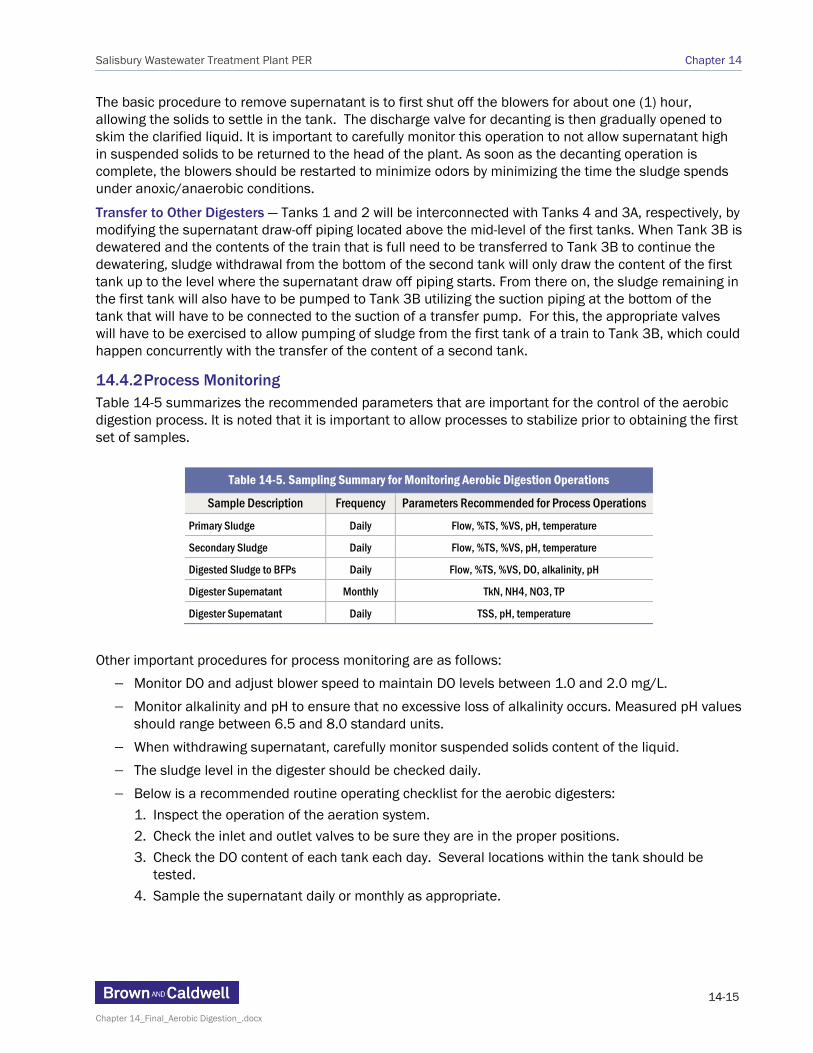
14.4.2 Process Monitoring Table 14-5 summarizes the recommended parameters that are important for the control of the aerobic digestion process. It is noted that it is important to allow processes to stabilize prior to obtaining the first set of samples.
Table 14-5. Sampling Summary for Monitoring Aerobic Digestion Operations
Sample Description Frequency Parameters Recommended for Process Operations
Primary Sludge Daily Flow, %TS, %VS, pH, temperature
Secondary Sludge Daily Flow, %TS, %VS, pH, temperature
Digested Sludge to BFPs Daily Flow, %TS, %VS, DO, alkalinity, pH
Digester Supernatant Monthly TkN, NH4, NO3, TP
Digester Supernatant Daily TSS, pH, temperature
Other important procedures for process monitoring are as follows:
Monitor DO and adjust blower speed to maintain DO levels between 1.0 and 2.0 mg/L.
Monitor alkalinity and pH to ensure that no excessive loss of alkalinity occurs. Measured pH values should range between 6.5 and 8.0 standard units.
When withdrawing supernatant, carefully monitor suspended solids content of the liquid.
The sludge level in the digester should be checked daily.
Below is a recommended routine operating checklist for the aerobic digesters:
1. Inspect the operation of the aeration system. 2. Check the inlet and outlet valves to be sure they are in the proper positions.
3. Check the DO content of each tank each day. Several locations within the tank should be tested.
4. Sample the supernatant daily or monthly as appropriate.

Salisbury Wastewater Treatment Plant PER Chapter 14
14-16
Chapter 14_Final_Aerobic Digestion_.docx
14.4.3 Startup/Shutdown Procedures
Tank Startup — (1) Check the blower for proper setting; (2) set the local switch to the “AUTO” position; (3) set the H-O-A switch on the main control panel in the “AUTO” position for the blower; (4) check the diffuser system for proper operation by observing the bubbling pattern on the surface of the tank when the sludge level is relatively low.
Tanks Shutdown — (1) Close all inlet/outlet valves; (2) set motor control H-O-A switch in the “OFF” position
Decanting — (1) Set the blower switch in the “OFF” position; (2) allow the tank to settle long enough for a good quality supernatant to form; (3) exercise (lower) supernatant control valve; (4) inspect the supernatant quality; (5) adjust the control valve if necessary; (6) reset all valves to their original positions after removing the desired amount of supernatant; (7) turn blower back on.
14.5 Relation to Other Unit Processes Performance of the aerobic digestion process affects the performance of the downstream heat drying process and the quality of the final biosolids. Most sludge drying facilities operate a stabilization process upstream of the dryer, the majority of which are typically digestion. A few dryer facilities operate an extended secondary process to reduce volatile solids in the sludge. Historically, a few plants did attempt to dry raw sludge, but failure of those operations for product stability and odor reasons resulted in their adding an upstream stabilization process. Without testing, it is difficult to predict what level of volatile solids reduction is required to produce good quality biosolids. Generally, an SRT of over 15 days should be the minimum target for good quality dried biosolids and the existing infrastructure will allow meeting that goal up to current plant flows of 5.5 MGD assuming a suspended growth activated sludge liquid treatment system. Pilot testing of the proposed replacement sludge dryer indicated that, under existing conditions, a good quality end product is achievable. At a minimum, the proposed modifications to the existing infrastructure and to the operational procedures should be performed. Replacement of the dryer with a more proven and reliable unit will avoid fires and explosions regardless of the performance of the upstream aerobic digestion, even at shorter SRTs. Shorter than 15-day SRTs are likely to result in a more odorous end product once the dried material gets wet again.
Also, performance of the thickening process through supernatant removal from the aerated tanks affects the efficiency of the downstream dewatering process and, to a lesser extent, the liquid process due to the solids returned back to the head of the plant for reprocessing. Typically, the sludge fed to the BFPs should have a minimum solids content of 1.7% in order to avoid excessive polymer dosing and production of wet cake. Thickening at the primary clarifiers may not be enough to accomplish this, so thickening may need to be supplemented with supernatant removal at the aerobic digesters as recommended. In addition, Salisbury is currently installing a ne water pocket decanting system on the sludge feed lines to the BFPs.
14.6 MDE Guidelines According to MDE as part of a sewage sludge utilization (SSU) permit application for distribution of treated sewage sludge by a process to significantly reduce pathogens (PSRP, a.k.a. Class B) and subsequent land application in Maryland, the Wastewater Treatment Plant (WWTP) owner/operator must demonstrate to the satisfaction of the Department that the sewage sludge treatment process meets the performance standards contained in the Code of Maryland Regulations (COMAR) 26.04.06.08 or the federal regulations under 40 CFR Part 503 for (1) Pathogen Control and (2) Vector Attraction Reduction. Compliance with the two types of requirements must be demonstrated separately and examples include the following:

Salisbury Wastewater Treatment Plant PER Chapter 14
14-17
Chapter 14_Final_Aerobic Digestion_.docx
Pathogen Control: The aerobic digestion process is conducted by agitating the sewage sludge with air or oxygen to maintain aerobic conditions for a specific MCRT at a specific temperature. Values for the MCRT and temperature must be between 40 days at 20°C (68°F) and 60 days at 15°C (59°F), with a volatile solids reduction of at least 38 percent.
Note: Although not explicitly listed in the information posted by MDE for a SSU permit application, under the federal regulations 40 CFR Part 503, an alternate way to demonstrate the pathogen control requirement includes demonstrating that seven samples of treated residuals contain fecal coliform densities of less than or equal to 2,000,000 CFU or MPN per gram total solids.
Vector Attraction Reduction: For aerobically digested sewage sludge, vector attraction reduction is demonstrated either (i) when the percent volatile solids reduction during sewage sludge treatment equals or exceeds 38%, or (ii) when the specific oxygen uptake rate (SOUR) at 20°C (68°F) is less than or equal to 1.5 mg of oxygen per hour per gram of total solids, or (iii) when additional volatile solids reduction during bench-scale aerobic batch digestion for 30 additional days at 20°C (68°F) is less than 15%.
Upon approval of the treated sewage sludge for land application, the WWTP must also comply with Maryland specific requirements regarding annual reporting and associated fees. The WWTP is also held liable to keep track and accurate records of the generated and utilized sewage sludge.
First, as demonstrated in Table 14-3, under current flow and treatment conditions, the time and temperature requirement of 60 days at 15°C (59°F) is met and it is a matter of minor piping modifications to demonstrate that the aerobic digesters produce Class B liquid sludge. Further expanding on the MCRT and temperature requirement, USEPA also states that for staged operation using two stages of approximately equal volume, the time required may be reduced to 70 percent of the time required for single-stage aerobic digestion in a continuously mixed reactor. The same reduction is recommended for batch operation or for more than two stages in series. Thus, the time required would be reduced from 60 days to 42 days at 15°C (59°F). These reduced times are also more than sufficient to achieve adequate vector attraction reduction. Once such performance is demonstrated, the process would have to be operated at time-temperature conditions that match the conditions of the tests.
Under the proposed suspended growth biological treatment process the existing aerobic digestion infrastructure will only allow to partially stabilize the sludge to produce dried biosolids of acceptable handling quality. The plant will rely on the heat drying process to reduce pathogen and vector attraction and meet Class AA or EQ standards.
14.7 Constructability The proposed modifications as part of this upgrade include adding piping and valves to interconnect the supernatant line of Tank 1 with the feed line of Tank 4 and the supernatant line of Tank 2 with the feed line of Tank 3A. Even though the proposed pipeline runs are relatively short and of small diameter (8 inches, the digestion headhouse is congested with piping and the tie-ins will be challenging to accomplish. Because the available record drawings for this area are not accurate, it is proposed during design to survey the existing piping using three-dimensional scanning technology (LIDAR). The proposed tie-ins will then be presented on three-dimension drawings. Piping modifications should be performed first to the tanks consisting of one train, before the same is performed to the tanks of the other train, to allow uninterrupted operation of the sludge storage and digestion process.
Installation of the aluminum covers on Tanks 1 and 2 and ductwork to a new package odor control system should not present any problem to construct. If the telescoping valves are removed from the first tanks there is no other equipment other than the air piping in and out that needs to penetrate the proposed covers. The proposed slab for the odor control system will be constructed either between Tanks 1 and 2 and the road to the north or in the area northwest of Tank 1. The only foreseeable issue

Salisbury Wastewater Treatment Plant PER Chapter 14
14-18
Chapter 14_Final_Aerobic Digestion_.docx
may be related to the available area and the footprint occupied by the proposed odor control system. In case that the two proposed locations cannot accommodate the proposed odor control system, the system should be installed in the unoccupied area west of the solids handling building.
Extending the secondary sludge force main back to the primary clarifier distribution box to be able to collect co-settled sludge from the underflow of the primary clarifiers can be done on a dry pipe by exercising the appropriate isolation valves in the yard north of the old thickener and PC2 structures. The proposed 8”SSL pipeline should be tied into the 8”PSL force main that already discharges into the PC distribution box.
If it is elected to send secondary sludge straight to the aerobic digesters, provisions for mixing of secondary sludge with primary sludge in the pipe are available since the primary and secondary sludge force mains are already interconnected near the sludge tanks. It is a matter of opening and closing the appropriate valves to be able to mix the two sludges together and divert them to the appropriate tank.
Even though transfer pumping to Tank 3B will not overlap between trains, to minimize the opening and closing of valves, sludge transfer pump 3 will be dedicated to the western train (Train A) consisting of Tanks 1 and 4, sludge transfer pump 1 or 2 will be dedicated to the eastern train (Train B) consisting of Tanks 2 and 3A and the remaining sludge transfer pump will be standby.
14.8 Future Expansion Issues The aerobic digestion process is generally not a sustainable process that would be recommended for future expansions beyond 8.5 MGD plant flows. The only viable future expansion is to gain additional digestion capacity without building any new tanks by separating the thickening process from the aerobic digestion process. An RDT or a membrane thickening system could be utilized to thicken raw secondary sludge before the sludge gets to the aerobic digesters. Upstream thickening will remove water and reduce the overall volume of sludge needing treatment; hence increase the detention time and capacity provided by the existing tanks.