chapter 2 data representation in computer systems · unsigned binary values to represent signed...
TRANSCRIPT

CMPS375 Class Notes (Chap02) Page 1 / 25 Dr. Kuo-pao Yang
CHAPTER 2
Data Representation in Computer Systems
2.1 Introduction 57
2.2 Positional Numbering Systems 58
2.3 Converting Between Bases 58 2.3.1 Converting Unsigned Whole Numbers 59
2.3.2 Converting Fractions 61
2.3.3 Converting between Power-of-Two Radices 64
2.4 Signed Integer Representation 64 2.4.1 Signed Magnitude 64
2.4.2 Complement Systems 70
2.4.3 Excess-M Representation for Signed Numbers 76
2.4.4 Unsigned Versus Signed Numbers 77
2.4.5 Computers, Arithmetic, and Booth’s Algorithm 78
2.4.6 Carry Versus Overflow 81
2.4.7 Binary Multiplication and Division Using Shifting 82
2.5 Floating-Point Representation 84 2.5.1 A Simple Model 85
2.5.2 Floating-Point Arithmetic 88
2.5.3 Floating-Point Errors 89
2.5.4 The IEEE-754 Floating-Point Standard 90
2.5.5 Range, Precision, and Accuracy 92
2.5.6 Additional Problems with Floating-Point Numbers 93
2.6 Character Codes 96 2.6.1 Binary-Coded Decimal 96
2.6.2 EBCDIC 98
2.6.3 ASCII 99
2.6.4 Unicode 99
2.7 Error Detection and Correction 103 2.7.1 Cyclic Redundancy Check 103
2.7.2 Hamming Codes 106
2.7.3 Reed-Soloman 113
Chapter Summary 114

CMPS375 Class Notes (Chap02) Page 2 / 25 Dr. Kuo-pao Yang
2.1 Introduction 57
This chapter describes the various ways in which computers can store and manipulate
numbers and characters.
Bit: The most basic unit of information in a digital computer is called a bit, which is a
contraction of binary digit.
Byte: In 1964, the designers of the IBM System/360 mainframe computer established
a convention of using groups of 8 bits as the basic unit of addressable computer
storage. They called this collection of 8 bits a byte.
Word: Computer words consist of two or more adjacent bytes that are sometimes
addressed and almost always are manipulated collectively. The word size represents
the data size that is handled most efficiently by a particular architecture. Words can
be 16 bits, 32 bits, 64 bits.
Nibbles: Eight-bit bytes can be divided into two 4-bit halves call nibbles.
2.2 Positional Numbering Systems 58
Radix (or Base): The general idea behind positional numbering systems is that a
numeric value is represented through increasing powers of a radix (or base).
System Radix Allowable Digits
---------------------------------------------------------------------
Decimal 10 0, 1, 2, 3, 4, 5, 6, 7, 8, 9
Binary 2 0, 1
Octal 8 0, 1, 2, 3, 4, 5, 6, 7
Hexadecimal 16 0, 1, 2, 3, 4, 5, 6, 7, 8, 9, A, B, C, D, E, F
TABLE 2.1 Some Number to Remember
EXAMPLE 2.1 Three numbers represented as powers of a radix.
243.5110 = 2 * 102 + 4 * 10
1 + 3 * 10
0 + 5 * 10
-1 + 1 * 10
-2
2123 = 2 * 32 + 1 * 3
1 + 2 * 3
0 = 2310
101102 = 1 * 24 + 0 * 2
3 + 1 * 2
2 + 1 * 2
1 + 0 * 2
0 = 2210
CMPS375 Class Notes (Chap02) Page 3 / 25 Dr. Kuo-pao Yang
2.3 Converting Between Bases 58
There are two important groups of number base conversions:
1. Conversion of decimal numbers to base-r numbers
2. Conversion of base-r numbers to decimal numbers
2.3.1 Converting Unsigned Whole Numbers 59
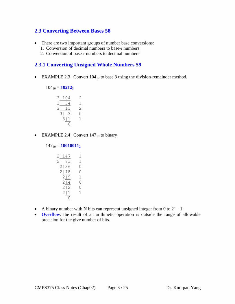
EXAMPLE 2.3 Convert 10410 to base 3 using the division-remainder method.
10410 = 102123
3|104 2
3| 34 1
3| 11 2
3| 3 0
3|1 1
0
EXAMPLE 2.4 Convert 14710 to binary
14710 = 100100112
2|147 1
2| 73 1
2|36 0
2|18 0
2|9 1
2|4 0
2|2 0
2|1 1
0
A binary number with N bits can represent unsigned integer from 0 to 2n – 1.
Overflow: the result of an arithmetic operation is outside the range of allowable
precision for the give number of bits.

CMPS375 Class Notes (Chap02) Page 4 / 25 Dr. Kuo-pao Yang
2.3.2 Converting Fractions 61
EXAMPLE 2.6 Convert 0.430410 to base 5.
0.430410 = 0.20345
0.4304
X 5
2.1520
X 5
0.7600
X 5
3.8000
X 5
4.0000
EXAMPLE 2.7 Convert 0.3437510 to binary with 4 bits to the right of the binary
point.
0.3437510 = 0.01012
0.34375
X 2
0.68750
X 2
1.37500
X 2
0.75000
X 2
1.50000
Reading from top to bottom, 0.3437510 = 0.01012 to four binary places. We simply
discard (or truncate) our answer when the desired accuracy has been achieved.

CMPS375 Class Notes (Chap02) Page 5 / 25 Dr. Kuo-pao Yang
EXAMPLE 2.8 Convert 31214 to base 3
First, convert to decimal 31214 = 3 * 43 + 1 * 4
2 + 2 * 4
1 + 1 * 4
0
= 3 * 64 + 1 * 16 + 2 * 4 + 1 * 1
= 21710
Then convert to base 3 21710 = 220013
3|217 1
3| 72 0
3| 24 0
3| 8 2
3|2 2
0
We have 31214 = 220013
2.3.3 Converting between Power-of-Two Radices 64
EXAMPLE 2.9 Convert 1100100111012 to octal and hexadecimal.
110 010 011 1012 = 62358 Separate into groups of 3 for octal conversion
1100 1001 11012 = C9D16 Separate into groups of 4 for octal conversion
CMPS375 Class Notes (Chap02) Page 6 / 25 Dr. Kuo-pao Yang
2.4 Signed Integer Representation 64
By convention, a “1” in the high-order bit indicate a negative number.
2.4.1 Signed Magnitude 64
A signed-magnitude number has a sign as its left-most bit (also referred to as the
high-order bit or the most significant bit) while the remaining bits represent the
magnitude (or absolute value) of the numeric value.
N bits can represent –(2n-1
- 1) to 2n-1
-1
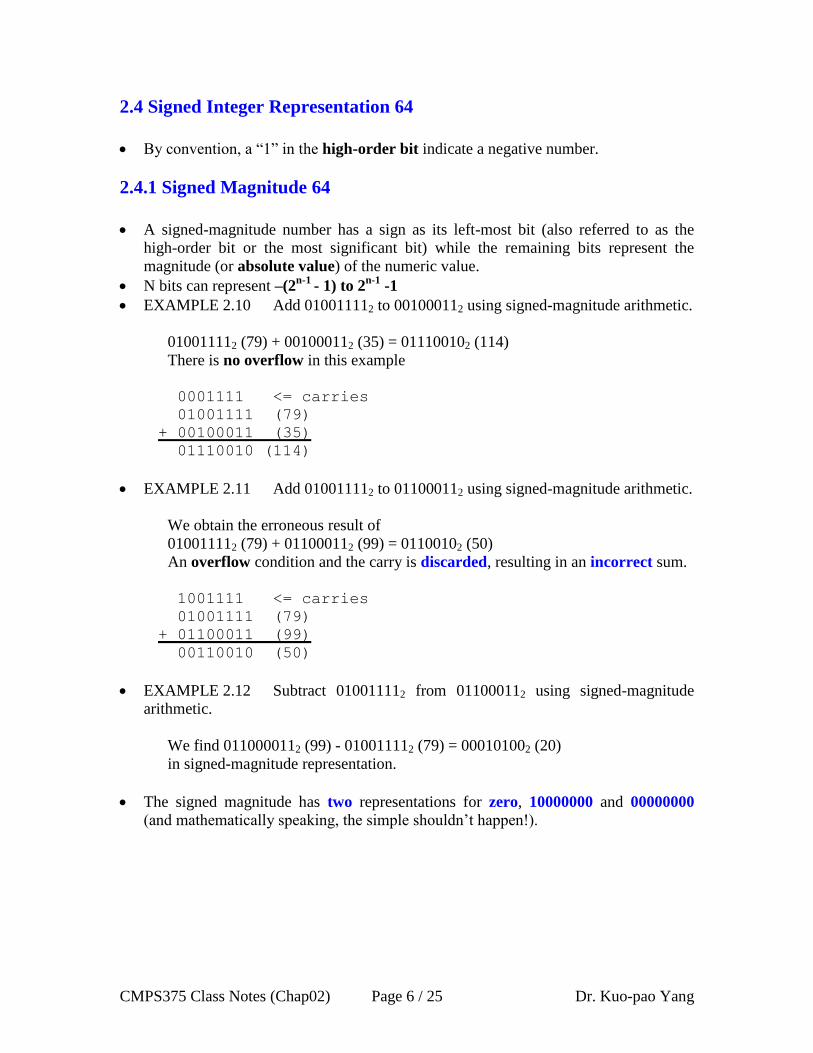
EXAMPLE 2.10 Add 010011112 to 001000112 using signed-magnitude arithmetic.
010011112 (79) + 001000112 (35) = 011100102 (114)
There is no overflow in this example
0001111 <= carries
01001111 (79)
+ 00100011 (35)
01110010 (114)
EXAMPLE 2.11 Add 010011112 to 011000112 using signed-magnitude arithmetic.
We obtain the erroneous result of
010011112 (79) + 011000112 (99) = 01100102 (50)
An overflow condition and the carry is discarded, resulting in an incorrect sum.
1001111 <= carries
01001111 (79)
+ 01100011 (99)
00110010 (50)
EXAMPLE 2.12 Subtract 010011112 from 011000112 using signed-magnitude
arithmetic.
We find 0110000112 (99) - 010011112 (79) = 000101002 (20)
in signed-magnitude representation.
The signed magnitude has two representations for zero, 10000000 and 00000000
(and mathematically speaking, the simple shouldn’t happen!).

CMPS375 Class Notes (Chap02) Page 7 / 25 Dr. Kuo-pao Yang
2.4.2 Complement Systems 70
One’s Complement
o This sort of bit-flipping is very simple to implement in computer hardware.
o EXAMPLE 2.16 Express 2310 and -910 in 8-bit binary one’s complement form.
2310 = + (000101112) = 000101112
-910 = - (000010012) = 111101102
The primary disadvantage of one’s complement is that we still have two
representations for zero: 00000000 and 11111111
Two’s Complement
o Find the one’s complement and add 1.
o EXAMPLE 2.20 Express 2310, -2310, and -910 in 8-bit binary two’s complement
form.
2310 = + (000101112) = 000101112
-2310 = - (000101112) = 111010002 + 1 = 111010012
-910 = - (000010012) = 111101102 + 1 = 111101112
o EXAMPLE 2.22 Add 910 to -2310 using two’s complement arithmetic.
000010012 (910) + 111010012 (-2310) = 111100102 (-1410)
00001001 <= Carries
000010012 ( 9)
+ 111010012 +(-23)
111100102 (-14)
o EXAMPLE 2.23 Find the sum of 2310 and -910 in binary using two’s complement
arithmetic.
000101112 (2310) + 111101112 (-910) = 000011102 (1410)
11110111 <= Carries
000101112 ( 23)
+ 111101112 +(- 9)
000011102 ( 14)

CMPS375 Class Notes (Chap02) Page 8 / 25 Dr. Kuo-pao Yang
o A Simple Rule for Detecting an Overflow Condition: If the carry in the sign bit
equals the carry out of the bit, no overflow has occurred. If the carry into the sign
bit is different from the carry out of the sign bit, over (and thus an error) has
occurred.
o EXAMPLE 2.22 Find the sum of 12610 and 810 in binary using two’s complement
arithmetic.
011111102 (12610) + 000010002 (810) = 100001102 (-12210)
01111000 <= Carries
011111102 ( 126)
+ 000010002 +( 8)
100001102 (-122)
A one is carried into the leftmost bit, but a zero is carried out. Because these
carries are not equal, an overflow has occurred.
o N bits can represent –(2n-1
) to (2n-1
-1). With signed-magnitude number, for
example, 4 bits allow us to represent the value -7 through +7. However, using
two’s complement, we can represent the value -8 through +7.

CMPS375 Class Notes (Chap02) Page 9 / 25 Dr. Kuo-pao Yang
Integer Multiplication and Division
o For each digit in the multiplier, the multiplicand is “shifted” one bit to the left.
When the multiplier is 1, the “shifted” multiplicand is added to a running sum of
partial products.
o EXAMPLE Find the product of 000001102 (610) and 000010112 (1110).
00000110 ( 6)
x 00001011 (11)
Multiplicand Partial Products
00000110 + 00000000 (1; add multiplicand and shift left)
00001100 + 00000110 (1; add multiplicand and shift left)
00011000 + 00010010 (0; Don’t add, just shift multiplicand left)
00110000 + 00010010 (1; add multiplicand and shift left)
= 01000010 (Product; 6 X 11 = 66)
o When the divisor is much smaller than the dividend, we get a condition known as
divide underflow, which the computer sees as the equivalent of division by zero.
o Computer makes a distinction between integer division and floating-point division.
With integer division, the answer comes in two parts: a quotient and a
remainder.
Floating-point division results in a number that is expressed as a binary
fraction.
Floating-point calculations are carried out in dedicated circuits call floating-
point units, or FPU.
CMPS375 Class Notes (Chap02) Page 10 / 25 Dr. Kuo-pao Yang
2.4.3 Excess-M Representation for Signed Numbers 76
Excess-M representation (also called offset binary representation) is another way for
unsigned binary values to represent signed integers.
Excess-M representation is intuitive because the binary string with all 0s represents
the smallest number, whereas the binary string with all 1s represents the largest
value.
An unsigned binary integer M (called the bias) represents the value 0, whereas all
zeroes in the bit pattern represents the integer -M.
The integer is interpreted as positive or negative depending on where it falls in the
range.
If n bits are used for the binary representation, we select the bias in such a manner
that we split the range equally. Typically, we choose a bias of 2n-1
- 1.
o For example, if we were using 4-bit representation, the bias should be 24 -1
- 1 = 7.
Just as with signed magnitude, one’s complement, and two’s complement, there is a
specific range of values that can be expressed in n bits.
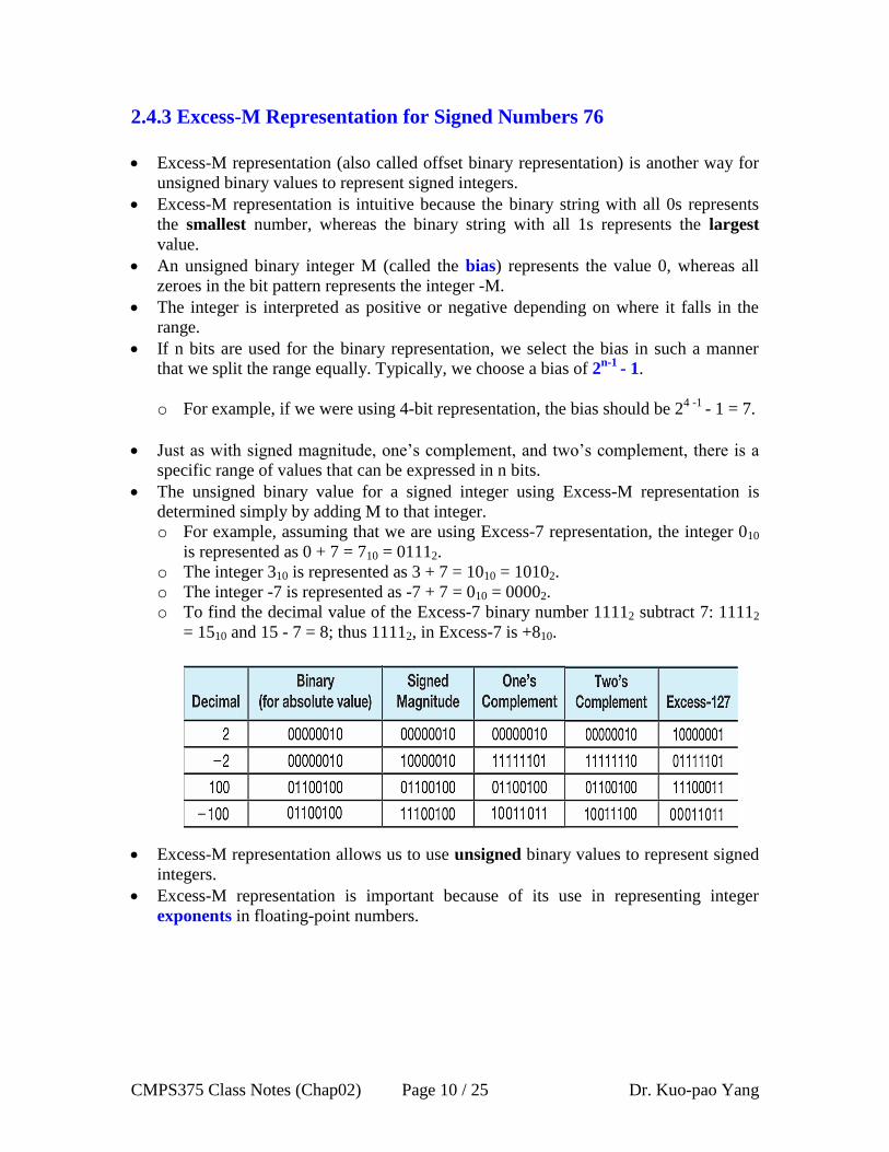
The unsigned binary value for a signed integer using Excess-M representation is
determined simply by adding M to that integer.
o For example, assuming that we are using Excess-7 representation, the integer 010
is represented as 0 + 7 = 710 = 01112.
o The integer 310 is represented as 3 + 7 = 1010 = 10102.
o The integer -7 is represented as -7 + 7 = 010 = 00002.
o To find the decimal value of the Excess-7 binary number 11112 subtract 7: 11112
= 1510 and 15 - 7 = 8; thus 11112, in Excess-7 is +810.
Excess-M representation allows us to use unsigned binary values to represent signed
integers.
Excess-M representation is important because of its use in representing integer
exponents in floating-point numbers.

CMPS375 Class Notes (Chap02) Page 11 / 25 Dr. Kuo-pao Yang
2.4.4 Unsigned Versus Signed Numbers 77
If the 4-bit binary value 1101 is unsigned, then it represents the decimal value 13, but
as a signed two’s complement number, it represents -3.
C programming language has int and unsigned int as possible types for integer
variables.
If we are using 4-bit unsigned binary numbers and we add 1 to 1111, we get 0000
(“return to zero”).
If we add 1 to the largest positive 4-bit two’s complement number 0111 (+7), we get
1000 (-8).

CMPS375 Class Notes (Chap02) Page 12 / 25 Dr. Kuo-pao Yang
2.4.5 Computers, Arithmetic, and Booth’s Algorithm 78
Consider the following standard pencil and paper method for multiplying two’s
complement numbers (-5 X -4):
1011 (-5)
x 1100 (-4)
+ 0000 (0 in multiplier means simple shift)
+ 0000 (0 in multiplier means simple shift)
+ 1011 (1 in multiplier means add multiplicand and shift)
+ 1011____ (1 in multiplier means add multiplicand and shift)
10000100 (-4 X -5 = -124)
Note that: “Regular” multiplication clearly yields the incorrect result.
Research into finding better arithmetic algorithms has continued apace for over 50
years. One of the many interesting products of this work is Booth’s algorithm.
In most cases, Booth’s algorithm carries out multiplication faster and more accurately
than naïve pencil-and-paper methods.
The general idea of Booth’s algorithm is to increase the speed of a multiplication
when there are consecutive zeros or ones in the multiplier.
Consider the following standard multiplication example (3 X 6):
0011 (3)
x 0110 (6)
+ 0000 (0 in multiplier means simple shift)
+ 0011 (1 in multiplier means add multiplicand and shift)
+ 0011 (1 in multiplier means add multiplicand and shift)
+ 0000____ (0 in multiplier means simple shift)
0010010 (3 X 6 = 18)
CMPS375 Class Notes (Chap02) Page 13 / 25 Dr. Kuo-pao Yang
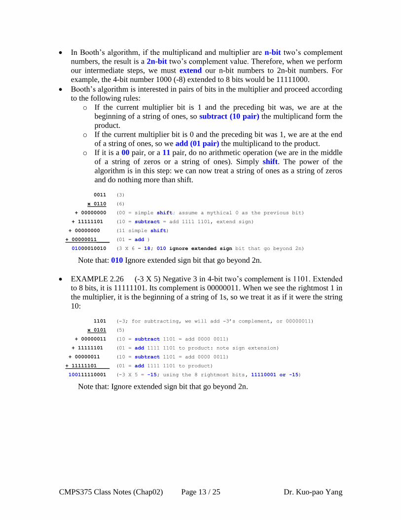
In Booth’s algorithm, if the multiplicand and multiplier are n-bit two’s complement
numbers, the result is a 2n-bit two’s complement value. Therefore, when we perform
our intermediate steps, we must extend our n-bit numbers to 2n-bit numbers. For
example, the 4-bit number 1000 (-8) extended to 8 bits would be 11111000.
Booth’s algorithm is interested in pairs of bits in the multiplier and proceed according
to the following rules:
o If the current multiplier bit is 1 and the preceding bit was, we are at the
beginning of a string of ones, so subtract (10 pair) the multiplicand form the
product.
o If the current multiplier bit is 0 and the preceding bit was 1, we are at the end
of a string of ones, so we add (01 pair) the multiplicand to the product.
o If it is a 00 pair, or a 11 pair, do no arithmetic operation (we are in the middle
of a string of zeros or a string of ones). Simply shift. The power of the
algorithm is in this step: we can now treat a string of ones as a string of zeros
and do nothing more than shift.
0011 (3)
x 0110 (6)
+ 00000000 (00 = simple shift; assume a mythical 0 as the previous bit)
+ 11111101 (10 = subtract = add 1111 1101, extend sign)
+ 00000000 (11 simple shift)
+ 00000011____ (01 = add )
01000010010 (3 X 6 = 18; 010 ignore extended sign bit that go beyond 2n)
Note that: 010 Ignore extended sign bit that go beyond 2n.
EXAMPLE 2.26 (-3 X 5) Negative 3 in 4-bit two’s complement is 1101. Extended
to 8 bits, it is 11111101. Its complement is 00000011. When we see the rightmost 1 in
the multiplier, it is the beginning of a string of 1s, so we treat it as if it were the string
10:
1101 (-3; for subtracting, we will add -3’s complement, or 00000011)
x 0101 (5)
+ 00000011 (10 = subtract 1101 = add 0000 0011)
+ 11111101 (01 = add 1111 1101 to product: note sign extension)
+ 00000011 (10 = subtract 1101 = add 0000 0011)
+ 11111101____ (01 = add 1111 1101 to product)
100111110001 (-3 X 5 = -15; using the 8 rightmost bits, 11110001 or -15)
Note that: Ignore extended sign bit that go beyond 2n.

CMPS375 Class Notes (Chap02) Page 14 / 25 Dr. Kuo-pao Yang
EXAMPLE 2.27 Let’s look at the larger example of 53 X 126:
00110101 (53; for subtracting, we will add the complement of 53 or 11001011)
x 01111110 (126)
+0000000000000000 (00 = simple shift)
+111111111001011 (10 = subtract = add 11001011, sign extension)
+00000000000000 (11 = simple shift)
+0000000000000 (11 = simple shift)
+000000000000 (11 = simple shift)
+00000000000 (11 = simple shift)
+0000000000 (11 = simple shift)
+000110101____ (01 = add 00110101, sign extension)
10001101000010110 (53 X 126 = 6678; using the 16 rightmost bits)
Note that: Ignore extended sign bit that go beyond 2n.
Booth’s algorithm not only allows multiplication to be performed faster in most cases,
but it also has the added bonus in that it works correctly on signed numbers.
2.4.6 Carry Versus Overflow 81
For unsigned numbers, a carry (out of the leftmost bit) indicates the total number of
bits was not large enough to hold the resulting value, and overflow has occurred.
For signed numbers, if the carry in to the sign bit and the carry (out of the sign bit)
differ, then overflow has occurred.
TABLE 2.2 Examples of Carry and Overflow in Signed Numbers
CMPS375 Class Notes (Chap02) Page 15 / 25 Dr. Kuo-pao Yang
2.4.7 Binary Multiplication and Division Using Shifting 82
We can do binary multiplication and division by 2 very easily using an arithmetic
shift operation
A left arithmetic shift inserts a 0 in for the rightmost bit and shifts everything else left
one bit; in effect, it multiplies by 2
A right arithmetic shift shifts everything one bit to the right, but copies the sign bit; it
divides by 2
EXAMPLE 2.28 Multiply the value 11 (expressed using 8-bit signed two’s
complement representation) by 2.
We start with the binary value for 11:
00001011 (+11)
We shift left one place, resulting in:
00010110 (+22)
The sign bit has not changed, so the value is valid.
To multiply 11 by 4, we simply perform a left shift twice.
EXAMPLE 2.31 Divide the value 12 (expressed using 8-bit signed two’s
complement representation) by 2.
We start with the binary value for 12:
00001100 (+12)
We shift right one place, resulting in:
00000110 (+6)
(Remember, we carry the sign bit to the left as we shift.)
To divide 12 by 4, we right shift twice.

CMPS375 Class Notes (Chap02) Page 16 / 25 Dr. Kuo-pao Yang
2.5 Floating-Point Representation 84
In scientific notion, numbers are expressed in two parts: a fractional part call a
mantissa, and an exponential part that indicates the power of ten to which the
mantissa should be raised to obtain the value we need.
2.5.1 A Simple Model 85
In digital computers, floating-point number consist of three parts: a sign bit, an
exponent part (representing the exponent on a power of 2), and a fractional part
called a significand (which is a fancy word for a mantissa).
1 bit 5 bits 8 bits
Sign bit Exponent Significand
FIGURE 2.1 Simple Model Floating-Point Representation
Unbiased Exponent
1710 = 0.100012 * 25
6553610 = 0.12 * 217
Biased Exponent: We select 15 because it is midway between 0 and 31 (our exponent
has 5 bits, thus allowing for 25 or 32 values). Any number larger than 15 in the
exponent field will represent a positive value. Value less than 15 will indicate
negative values. This is called an Excess-15 representation because we have to
subtract 15 to get the true value of the exponent.
1710 = 0.100012 * 25
The biased exponent is 15 + 5 = 20 (101002)
0.2510 = 0.12 * 2-1
The biased exponent is 15 - 1 = 14 (011102)
A normalized form is used for storing a floating-point number in memory. A
normalized form is a floating-point representation where the leftmost bit of the
significand will always be a 1.
Example: Internal representation of (10.25)10
(10.25)10 = (1010.01) 2 (Un-normalized form)
= (1010.01) 2 x 20 .
= (101.001) 2 x 21 .
:
= (.101001) 2 x 24 (Normalized form)
= (.0101001) 2 x 25
(Un-normalized form)
= (.00101001) 2 x 2
6 .
Internal representation of (10.25)10 is 0 10011 10100100
0 00101 10001000
0 10001 10000000
0 10100 10001000
0 01110 10000000

CMPS375 Class Notes (Chap02) Page 17 / 25 Dr. Kuo-pao Yang
2.5.2 Floating-Point Arithmetic 88
EXAMPLE 2.35 Add the following binary numbers as represented in a normalized
14-bit format, using the simple model with a bias of 15.
= 0.11001000 X 22
+
= 0.10011010 X 20
11.001000
+ 0.10011010
11.10111010
Renormalizing we retain the larger exponent and truncate the low-order bit.
EXAMPLE 2.36 Multiply:
= 0.11001000 X 23
X
= 0.10011010 X 21
11001000
x 10011010
00000000
11001000
00000000
11001000
11001000
00000000
00000000
11001000_______
111100001010000
Renormalizing 0.0111100001010000 * 24 = 0.111100001010000 * 2
3 we retain the
larger exponent and truncate the low-order bit.
0 10001 11001000
0 01111 10011010
0 10001 11101110
0 10010 11001000
0 10000 10011010
0 10010 11110000

CMPS375 Class Notes (Chap02) Page 18 / 25 Dr. Kuo-pao Yang
2.5.3 Floating-Point Errors 89
We intuitively understand that we are working in the system of real number. We
know that this system is infinite.
Computers are finite systems, with finite storage. The more bits we use, the better the
approximation. However, there is always some element of error, no matter how
many bits we use.
Table 2.3 Error Propagation in a 14-Bit Floating-Point Number
2.5.4 The IEEE-754 Floating-Point Standard 90
The IEEE-754 single precision floating point standard uses an 8-bit exponent (with a
bias of 127) and a 23-bit significand. An exponent of 255 indicates a special value.
The IEEE-754 double precision standard uses an 11-bit exponent (with a bias of
1023) and a 52-bit significand. The “special” exponent value for a double precision
number is 2047, instead of the 255 used by the single precision standard.
Figure 2.2 IEEE-754 Single Precision Floating-Point Representation

CMPS375 Class Notes (Chap02) Page 19 / 25 Dr. Kuo-pao Yang
In both the IEEE single-precision and double-precision floating-point standard, the
significant has an implied 1 to the LEFT of the radix point.
o The format for a significand using the IEEE format is: 1.xxx…
o For example, 4.5 = 100.12 = .1001 x 23 in IEEE format is 4.5 = 1.001 x 2
2. The 1
is implied, which means is does not need to be listed in the significand (the
significand would include only 001).
o This implied 1 is referred to as the hidden bit or hidden 1 and allows an actual
significand of 23 + 1 = 24 bits.
Table 2.4 Some Example IEEE-754 Single-Precision Floating-Point Numbers
2.5.5 Range, Precision, and Accuracy 92
The range of a numeric integer format is the difference between the largest and
smallest values that is can express.
The precision of a number indicates how much information we have about a value
Accuracy refers to how closely a numeric representation approximates a true value.
2.5.6 Additional Problems with Floating-Point Numbers 93
Because of truncated bits, you cannot always assume that a particular floating point
operation is commutative or distributive.
This means that we cannot assume:
(a + b) + c = a + (b + c)
or
a * (b + c) = ab + ac

CMPS375 Class Notes (Chap02) Page 20 / 25 Dr. Kuo-pao Yang
2.6 Character Codes 96
Thus, human-understandable characters must be converted to computer-
understandable bit patterns using some sort of character encoding scheme.
2.6.1 Binary-Coded Decimal 96
Binary-coded Decimal (BCD) is a numeric coding system used primarily in IBM
mainframe and midrange systems in the 1950s and 1960s.
BCD is very common in electronics, particularly those that display numerical data,
such as alarm clocks and calculators.
BCD encodes each digit of a decimal number into a 4-bit binary form.
When stored in an 8-bit byte, the upper nibble is called the zone and the lower part is
called the digit.
TABLE 2.5 Binary-Coded Decimal
2.6.2 EBCDIC 98
In 1964, BCD was extended to an 8-bit code, Extended Binary-Coded Decimal
Interchange Code (EBCDIC).
EBCDIC was one of the first widely-used computer codes that supported upper and
lowercase alphabetic characters, in addition to special characters, such as punctuation
and control characters.
EBCDIC and BCD are still in use by IBM mainframes today. See TABLE 2.6
CMPS375 Class Notes (Chap02) Page 21 / 25 Dr. Kuo-pao Yang
2.6.3 ASCII 99
ASCII: American Standard Code for Information Interchange
In 1967, a derivative of this alphabet became the official standard that we now call
ASCII.
2.6.4 Unicode 99
Both EBCDIC and ASCII were built around the Latin alphabet.
In 1991, a new international information exchange code called Unicode.
Unicode is a 16-bit alphabet that is downward compatible with ASCII and Latin-1
character set.
Because the base coding of Unicode is 16 bits, it has the capacity to encode the
majority of characters used in every language of the world.
Unicode is currently the default character set of the Java programming language.
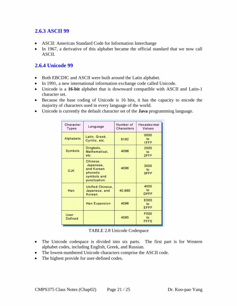
TABLE 2.8 Unicode Codespace
The Unicode codespace is divided into six parts. The first part is for Western
alphabet codes, including English, Greek, and Russian.
The lowest-numbered Unicode characters comprise the ASCII code.
The highest provide for user-defined codes.
CMPS375 Class Notes (Chap02) Page 22 / 25 Dr. Kuo-pao Yang
2.7 Error Detection and Correction 103
No communications channel or storage medium can be completely error-free.
2.7.1 Cyclic Redundancy Check 103
Cyclic redundancy check (CRC) is a type of checksum used primarily in data
communications that determines whether an error has occurred within a large block or
stream of information bytes.
Arithmetic Modulo 2 The rules are as follows:
0 + 0 = 0
0 + 1 = 1
1 + 0 = 1
1 + 1 = 0
EXAMPLE 2.38 Find the sum of 10112 and 1102 modulo 2.
10112 + 1102 = 11012 (mod 2)
EXAMPLE 2.39 Find the quotient and remainder when 10010112 is divided by 10112.
Quotient 10102 and Remainder 1012
Calculating and Using CRC
o Suppose we want to transmit the information string: 10010112.
o The receiver and sender decide to use the (arbitrary) polynomial pattern, 1011.
o The information string is shifted left by one position less than the number of
positions in the divisor. I = 10010110002
o The remainder is found through modulo 2 division (at right) and added to the
information string: 10010110002 + 1002 = 10010111002.
o If no bits are lost or corrupted, dividing the received information string by the
agreed upon pattern will give a remainder of zero.
o We see this is so in the calculation at the right.
o Real applications use longer polynomials to cover larger information strings.
A remainder other than zero indicates that an error has occurred in the transmission.
This method works best when a large prime polynomial is used.
There are four standard polynomials used widely for this purpose:
o CRC-CCITT (ITU-T): X16
+ X12
+ X5 + 1
o CRC-12: X12
+ X11
+ X3 + X
2 + X + 1
o CRC-16 (ANSI): X16
+ X15
+ X2 + 1
o CRC-32: X32
+ X26
+ X23
+ X22
+ X16
+ X12
+ X11
+ X10
+ X8 + X
7 + X
6 + X
4 + X
+ 1
CRC-32 has been proven that CRCs using these polynomials can detect over 99.8%
of all single-bit errors.
CMPS375 Class Notes (Chap02) Page 23 / 25 Dr. Kuo-pao Yang
2.7.2 Hamming Codes 106
Data communications channels are simultaneously more error-prone and more
tolerant of errors than disk systems.
Hamming code use parity bits, also called check bits or redundant bits.
The final word, called a code word is an n-bit unit containing m data bits and r check
bits.
n = m + r
The Hamming distance between two code words is the number of bits in which two
code words differ.
10001001
10110001
*** Hamming distance of these two code words is 3
The minimum Hamming distance, D(min), for a code is the smallest Hamming
distance between all pairs of words in the code.
Hamming codes can detect (D(min) - 1) errors and correct [(D(min) – 1) / 2] errors.
EXAMPLE 2.41
00000
01011
10110
11101
D(min) = 3. Thus, this code can detect up to two errors and correct one single bit
error.
We are focused on single bit error. An error could occur in any of the n bits, so each
code word can be associated with n erroneous words at a Hamming distance of 1.
Therefore, we have n + 1 bit patterns for each code word: one valid code word, and n
erroneous words. With n-bit code words, we have 2n possible code words consisting
of 2m
data bits (where m = n + r).
This gives us the inequality:
(n + 1) * 2m
< = 2n
Because m = n + r, we can rewrite the inequality as:
(m + r + 1) * 2m
<= 2 m + r
or
(m + r + 1) <= 2r

CMPS375 Class Notes (Chap02) Page 24 / 25 Dr. Kuo-pao Yang
EXAMPLE 2.42 Using the Hamming code just described and even parity, encode
the 8-bit ASCII character K. (The high-order bit will be zero.) Induce a single-bit
error and then indicate how to locate the error.
m = 8, we have (8 + r + 1) <= 2r then we choose r = 4
Parity bit at 1, 2, 4, 8
Char K 7510 = 010010112
1 = 1 5 = 1 + 4 9 = 1 + 8
2 = 2 6 = 2 + 4 10 = 2 + 8
3 = 1 + 2 7 = 1 + 2 + 4 11 = 1 + 2 + 8
4 = 4 8 = 8 12 = 4 + 8
We have the following code word as a result:
0 1 0 0 1 1 0 1 0 1 1 0
12 11 10 9 8 7 6 5 4 3 2 1
Parity b1 = b3 + b5 + b7 + b9 + b11 = 1 + 1 + 1 + 0 + 1 = 0
Parity b2 = b3 + b6 + b7 + b10 + b11 = 1 + 0 + 1 + 0 + 1 = 1
Parity b4 = b5 + b6 + b7 + b12 = 1 + 0 + 1 + 0 = 0
Parity b8 = b9 + b10 + b11 + b12 = 0 + 0 + 1 + 0 = 1
Let’s introduce an error in bit position b9, resulting in the code word:
0 1 0 1 1 1 0 1 0 1 1 0
12 11 10 9 8 7 6 5 4 3 2 1
Parity b1 = b3 + b5 + b7 + b9 + b11 = 1 + 1 + 1 + 1 + 1 = 1 (Error, should be 0)
Parity b2 = b3 + b6 + b7 + b10 + b11 = 1 + 0 + 1 + 0 + 1 = 1 (OK)
Parity b4 = b5 + b6 + b7 + b12 = 1 + 0 + 1 + 0 = 0 (OK)
Parity b8 = b9 + b10 + b11 + b12 = 1 + 0 + 1 + 0 = 0 (Error, should be 1)
We found that parity bits 1 and 8 produced an error, and 1 + 8 = 9, which in exactly
where the error occurred.

CMPS375 Class Notes (Chap02) Page 25 / 25 Dr. Kuo-pao Yang
2.7.3 Reed-Soloman 113
If we expect errors to occur in blocks, it stands to reason that we should use an error-
correcting code that operates at a block level, as opposed to a Hamming code, which
operates at the bit level.
A Reed-Soloman (RS) code can be thought of as a CRC that operates over entire
characters instead of only a few bits.
RS codes, like CRCs, are systematic: The parity bytes are append to a block of
information bytes.
RS (n, k) code are defined using the following parameters:
o s = The number of bits in a character (or “symbol”).
o k = The number of s-bit characters comprising the data block.
o n = The number of bits in the code word.
RS (n, k) can correct (n-k)/2 errors in the k information bytes.
Reed-Soloman error-correction algorithms lend themselves well to implementation in
computer hardware.
They are implemented in high-performance disk drives for mainframe computers as
well as compact disks used for music and data storage. These implementations will be
described in Chapter 7.
Chapter Summary 114
Computers store data in the form of bits, bytes, and words using the binary
numbering system.
Hexadecimal numbers are formed using four-bit groups called nibbles (or nybbles).
Signed integers can be stored in one’s complement, two’s complement, or signed
magnitude representation.
Floating-point numbers are usually coded using the IEEE 754 floating-point
standard.
Character data is stored using ASCII, EBCDIC, or Unicode.
Error detecting and correcting codes are necessary because we can expect no
transmission or storage medium to be perfect.
CRC, Reed-Soloman, and Hamming codes are three important error control codes.