chapter 2 part b: 2.0 litre dohc engine - ford euro faqfaq.ford77.ru/pdf/scorpio/1245-02b.pdf ·...
TRANSCRIPT

Chapter 2 Part B:2.0 litre DOHC engine Unless otherwise stated, procedures are as described for the SOHC engines in Part A of this Chapter
Camshafts and cam followers - removal, inspection and refitting . .21Compression test - description and interpretation . . . . . . . . . . . . .35Crankcase ventilation system - general information . . . . . . . . . . . . .2Crankshaft and bearings - examination and renovation . . . . . . . . .31Crankshaft and main bearings - removal and refitting . . . . . . . . . . .30Crankshaft front oil seal - renewal . . . . . . . . . . . . . . . . . . . . . . . . . .23Crankshaft rear oil seal - renewal . . . . . . . . . . . . . . . . . . . . . . . . . . .24Cylinder head - dismantling and reassembly . . . . . . . . . . . . . . . . . .19Cylinder head - inspection and renovation . . . . . . . . . . . . . . . . . . .20Cylinder head - removal and refitting (engine in vehicle) . . . . . . . . .17Cylinder head - removal and refitting (engine removed) . . . . . . . . .18Engine/automatic transmission assembly - reconnection and
refitting . . . . . . . . . . . . . . . . . . . . . . . . . . . . . . . . . . . . . . . . . . . . .12Engine/automatic transmission assembly - removal and separation .8Engine dismantling - general information . . . . . . . . . . . . . . . . . . . . .14Engine/manual gearbox assembly - reconnection and refitting . . . .11Engine/manual gearbox assembly - removal and separation . . . . . .7Engine mountings - renewal . . . . . . . . . . . . . . . . . . . . . . . . . . . . . . .13Engine reassembly - general information . . . . . . . . . . . . . . . . . . . . .33
Engine - refitting (automatic transmission in vehicle) . . . . . . . . . . . .10Engine - refitting (manual gearbox in vehicle) . . . . . . . . . . . . . . . . . .9Engine - removal leaving automatic transmission in vehicle . . . . . . .6Engine - removal leaving manual gearbox in vehicle . . . . . . . . . . . . .5Examination and renovation - general information . . . . . . . . . . . . .32Flywheel/driveplate - removal, inspection and refitting . . . . . . . . . .22General information . . . . . . . . . . . . . . . . . . . . . . . . . . . . . . . . . . . . . .1Initial start-up after overhaul or major repair . . . . . . . . . . . . . . . . . .34Major operations possible with the engine in the vehicle . . . . . . . . .3Major operations requiring engine removal . . . . . . . . . . . . . . . . . . . .4Oil pump - dismantling, inspection and reassembly . . . . . . . . . . . .27Oil pump drive chain and sprockets - examination and renovation .28Oil pump - removal and refitting . . . . . . . . . . . . . . . . . . . . . . . . . . . .26Pistons and connecting rods - removal and refitting . . . . . . . . . . . .29Sump - removal and refitting . . . . . . . . . . . . . . . . . . . . . . . . . . . . . .25Timing chain and sprockets - removal and refitting . . . . . . . . . . . . .15Timing chain, sprockets and tensioner - examination and
renovation . . . . . . . . . . . . . . . . . . . . . . . . . . . . . . . . . . . . . . . . . . .16
GeneralManufacturer’s code:
Carburettor engine . . . . . . . . . . . . . . . . . . . . . . . . . . . . . . . . . . . . . . . N8BFuel-injection engine without catalyst . . . . . . . . . . . . . . . . . . . . . . . . N9BFuel-injection engine with catalyst . . . . . . . . . . . . . . . . . . . . . . . . . . . N9D
Bore - mm (in) . . . . . . . . . . . . . . . . . . . . . . . . . . . . . . . . . . . . . . . . . . . . . 86.00 (3.386)Stroke - mm (in) . . . . . . . . . . . . . . . . . . . . . . . . . . . . . . . . . . . . . . . . . . . 86.00 (3.386)Cubic capacity - cc (cu in) . . . . . . . . . . . . . . . . . . . . . . . . . . . . . . . . . . . 1998 (121.9)Compression ratio . . . . . . . . . . . . . . . . . . . . . . . . . . . . . . . . . . . . . . . . . 10.3:1Compression pressure at cranking speed . . . . . . . . . . . . . . . . . . . . . . . 11 to 13 bar (160 to 189 lbf/in2)Maximum power (DIN, kW @ rpm):
N8B engine . . . . . . . . . . . . . . . . . . . . . . . . . . . . . . . . . . . . . . . . . . . . . 80 @ 5600N9B engine . . . . . . . . . . . . . . . . . . . . . . . . . . . . . . . . . . . . . . . . . . . . . 92 @ 5500N9D engine . . . . . . . . . . . . . . . . . . . . . . . . . . . . . . . . . . . . . . . . . . . . . 88 @ 5500
Maximum torque (DIN, Nm @ rpm):N8B engine . . . . . . . . . . . . . . . . . . . . . . . . . . . . . . . . . . . . . . . . . . . . . 174 @ 3000N9B engine . . . . . . . . . . . . . . . . . . . . . . . . . . . . . . . . . . . . . . . . . . . . . 174 @ 2500N9D engine . . . . . . . . . . . . . . . . . . . . . . . . . . . . . . . . . . . . . . . . . . . . . 171 @ 2500
Lubrication systemOil type . . . . . . . . . . . . . . . . . . . . . . . . . . . . . . . . . . . . . . . . . . . . . . . . . . See “Lubricants and fluids”Oil capacity:
With filter . . . . . . . . . . . . . . . . . . . . . . . . . . . . . . . . . . . . . . . . . . . . . . . 4.5 litres (7.92 pints)Without filter . . . . . . . . . . . . . . . . . . . . . . . . . . . . . . . . . . . . . . . . . . . . 4.0 litres (7.04 pints)
2B•1
Easy, suitable fornovice with littleexperience
Fairly easy, suitablefor beginner withsome experience
Fairly difficult,suitable for competentDIY mechanic
Difficult, suitable forexperienced DIYmechanic
Very difficult,suitable for expertDIY or professional
Degrees of difficulty
Specifications
Contents
2B

2B•2 DOHC engine
Cylinder blockBore diameter:
Standard grade 1 . . . . . . . . . . . . . . . . . . . . . . . . . . . . . . . . . . . . . . . . 86.000 to 86.010 mmStandard grade 2 . . . . . . . . . . . . . . . . . . . . . . . . . . . . . . . . . . . . . . . . 86.010 to 86.020 mmOversize 0.15 grade A . . . . . . . . . . . . . . . . . . . . . . . . . . . . . . . . . . . . . 86.150 to 86.160 mmOversize 0.15 grade B . . . . . . . . . . . . . . . . . . . . . . . . . . . . . . . . . . . . . 86.160 to 86.170 mmOversize 0.5 . . . . . . . . . . . . . . . . . . . . . . . . . . . . . . . . . . . . . . . . . . . . 86.500 to 86.510 mm
CrankshaftEndfloat . . . . . . . . . . . . . . . . . . . . . . . . . . . . . . . . . . . . . . . . . . . . . . . . . . 0.090 to 0.300 mmMain bearing running clearance . . . . . . . . . . . . . . . . . . . . . . . . . . . . . . . 0.011 to 0.048 mmMain bearing journal diameter:
Standard (yellow) . . . . . . . . . . . . . . . . . . . . . . . . . . . . . . . . . . . . . . . . 54.980 to 54.990 mmStandard (red) . . . . . . . . . . . . . . . . . . . . . . . . . . . . . . . . . . . . . . . . . . . 54.990 to 55.000 mmUndersize 0.25 (green) . . . . . . . . . . . . . . . . . . . . . . . . . . . . . . . . . . . . 54.730 to 54.750 mm
Main bearing thrustwasher thickness:Standard . . . . . . . . . . . . . . . . . . . . . . . . . . . . . . . . . . . . . . . . . . . . . . . 2.301 to 2.351 mmOversize 0.38 (yellow) . . . . . . . . . . . . . . . . . . . . . . . . . . . . . . . . . . . . . 2.491 to 2.541 mm
Big-end bearing running clearance . . . . . . . . . . . . . . . . . . . . . . . . . . . . 0.006 to 0.060 mmBig-end bearing journal diameter:
Standard . . . . . . . . . . . . . . . . . . . . . . . . . . . . . . . . . . . . . . . . . . . . . . . 50.890 to 50.910 mmUndersize 0.25 (green) . . . . . . . . . . . . . . . . . . . . . . . . . . . . . . . . . . . . 50.640 to 50.660 mm
Pistons and piston ringsPiston diameter:
Standard 1 . . . . . . . . . . . . . . . . . . . . . . . . . . . . . . . . . . . . . . . . . . . . . 85.970 to 85.980 mmStandard 2 . . . . . . . . . . . . . . . . . . . . . . . . . . . . . . . . . . . . . . . . . . . . . 85.980 to 85.990 mmStandard service . . . . . . . . . . . . . . . . . . . . . . . . . . . . . . . . . . . . . . . . . 85.980 to 86.000 mmOversize 0.15 . . . . . . . . . . . . . . . . . . . . . . . . . . . . . . . . . . . . . . . . . . . 86.130 to 86.150 mmOversize 0.50 . . . . . . . . . . . . . . . . . . . . . . . . . . . . . . . . . . . . . . . . . . . 86.470 to 86.490 mm
Piston ring end gap:Top . . . . . . . . . . . . . . . . . . . . . . . . . . . . . . . . . . . . . . . . . . . . . . . . . . . 0.300 to 0.600 mmCentre . . . . . . . . . . . . . . . . . . . . . . . . . . . . . . . . . . . . . . . . . . . . . . . . . 0.500 to 0.800 mmBottom (oil control) . . . . . . . . . . . . . . . . . . . . . . . . . . . . . . . . . . . . . . . 0.400 to 1.500 mm
Cylinder headValve guide bore . . . . . . . . . . . . . . . . . . . . . . . . . . . . . . . . . . . . . . . . . . . 7.063 to 7.094 mmCamshaft bearing parent bore diameter . . . . . . . . . . . . . . . . . . . . . . . . . 26.000 to 26.030 mm
CamshaftsEndfloat . . . . . . . . . . . . . . . . . . . . . . . . . . . . . . . . . . . . . . . . . . . . . . . . . . 0.020 to 0.260 mm
Valves and valve springs - generalValve timing:
Carburettor engine:Inlet opens . . . . . . . . . . . . . . . . . . . . . . . . . . . . . . . . . . . . . . . . . . . . 13°BTDCInlet closes . . . . . . . . . . . . . . . . . . . . . . . . . . . . . . . . . . . . . . . . . . . 39°ABDCExhaust opens . . . . . . . . . . . . . . . . . . . . . . . . . . . . . . . . . . . . . . . . 43°BBDCExhaust closes . . . . . . . . . . . . . . . . . . . . . . . . . . . . . . . . . . . . . . . . 13°ATDC
Fuel-injection engines:Inlet opens . . . . . . . . . . . . . . . . . . . . . . . . . . . . . . . . . . . . . . . . . . . . 13°BTDCInlet closes . . . . . . . . . . . . . . . . . . . . . . . . . . . . . . . . . . . . . . . . . . . 51°ABDCExhaust opens . . . . . . . . . . . . . . . . . . . . . . . . . . . . . . . . . . . . . . . . 43°BBDCExhaust closes . . . . . . . . . . . . . . . . . . . . . . . . . . . . . . . . . . . . . . . . 13°ATDC
Valve spring free length:Inner spring . . . . . . . . . . . . . . . . . . . . . . . . . . . . . . . . . . . . . . . . . . . . . 48.200 mmOuter spring . . . . . . . . . . . . . . . . . . . . . . . . . . . . . . . . . . . . . . . . . . . . 46.800 mm
Inlet valve stem diameter:Standard . . . . . . . . . . . . . . . . . . . . . . . . . . . . . . . . . . . . . . . . . . . . . . . 7.025 to 7.043 mmOversize 0.2 . . . . . . . . . . . . . . . . . . . . . . . . . . . . . . . . . . . . . . . . . . . . 7.225 to 7.243 mmOversize 0.4 . . . . . . . . . . . . . . . . . . . . . . . . . . . . . . . . . . . . . . . . . . . . 7.425 to 7.443 mmOversize 0.6 . . . . . . . . . . . . . . . . . . . . . . . . . . . . . . . . . . . . . . . . . . . . 7.625 to 7.643 mmOversize 0.8 . . . . . . . . . . . . . . . . . . . . . . . . . . . . . . . . . . . . . . . . . . . . 7.825 to 7.843 mm
Exhaust valve stem diameter:Standard . . . . . . . . . . . . . . . . . . . . . . . . . . . . . . . . . . . . . . . . . . . . . . . 6.999 to 7.017 mmOversize 0.2 . . . . . . . . . . . . . . . . . . . . . . . . . . . . . . . . . . . . . . . . . . . . 7.199 to 7.217 mmOversize 0.4 . . . . . . . . . . . . . . . . . . . . . . . . . . . . . . . . . . . . . . . . . . . . 7.399 to 7.417 mmOversize 0.6 . . . . . . . . . . . . . . . . . . . . . . . . . . . . . . . . . . . . . . . . . . . . 7.599 to 7.617 mmOversize 0.8 . . . . . . . . . . . . . . . . . . . . . . . . . . . . . . . . . . . . . . . . . . . . 7.799 to 7.817 mm

DOHC engine 2B•3
2B
Torque wrench settings Nm lbf ftMain bearing cap bolts . . . . . . . . . . . . . . . . . . . . . . . . . . . . . . . . . . . . . . 90 to 104 66 to 77Big-end bearing cap bolts:
Stage 1 . . . . . . . . . . . . . . . . . . . . . . . . . . . . . . . . . . . . . . . . . . . . . . . . 6 to 8 4 to 6Stage 2 . . . . . . . . . . . . . . . . . . . . . . . . . . . . . . . . . . . . . . . . . . . . . . . . 15 to 17 11 to 13Stage 3 . . . . . . . . . . . . . . . . . . . . . . . . . . . . . . . . . . . . . . . . . . . . . . . . Tighten further 85° to 95° Tighten further 85° to 95°
Crankshaft pulley bolt:Stage 1 . . . . . . . . . . . . . . . . . . . . . . . . . . . . . . . . . . . . . . . . . . . . . . . . 45 to 58 33 to 43Stage 2 . . . . . . . . . . . . . . . . . . . . . . . . . . . . . . . . . . . . . . . . . . . . . . . . Tighten further 80° to 90° Tighten further 80° to 90°
Camshaft sprocket bolts . . . . . . . . . . . . . . . . . . . . . . . . . . . . . . . . . . . . 55 to 63 41 to 46Flywheel bolts . . . . . . . . . . . . . . . . . . . . . . . . . . . . . . . . . . . . . . . . . . . . . 82 to 92 61 to 68Oil pump bolts . . . . . . . . . . . . . . . . . . . . . . . . . . . . . . . . . . . . . . . . . . . . 9 to 12 7 to 9Oil pump sprocket bolt . . . . . . . . . . . . . . . . . . . . . . . . . . . . . . . . . . . . . . 16 to 19 12 to 14Oil pump chain tensioner bolt . . . . . . . . . . . . . . . . . . . . . . . . . . . . . . . . . 10 to 13 7 to 10Sump bolts and nuts . . . . . . . . . . . . . . . . . . . . . . . . . . . . . . . . . . . . . . . . 8 to 10 6 to 7Sump studs . . . . . . . . . . . . . . . . . . . . . . . . . . . . . . . . . . . . . . . . . . . . . . . 6 to 8 4 to 6Sump drain plug . . . . . . . . . . . . . . . . . . . . . . . . . . . . . . . . . . . . . . . . . . . 21 to 28 15 to 21Sump front mounting plate . . . . . . . . . . . . . . . . . . . . . . . . . . . . . . . . . . . 23 to 28 17 to 21Oil baffle nuts . . . . . . . . . . . . . . . . . . . . . . . . . . . . . . . . . . . . . . . . . . . . . 17 to 21 13 to 15Oil pick-up pipe-to-cylinder block bolts . . . . . . . . . . . . . . . . . . . . . . . . . 9 to 13 7 to 10Oil pressure warning lamp switch . . . . . . . . . . . . . . . . . . . . . . . . . . . . . . 18 to 22 13 to 16Cylinder head bolts:
M11 bolts:Stage 1 . . . . . . . . . . . . . . . . . . . . . . . . . . . . . . . . . . . . . . . . . . . . . . 25 18Stage 2 . . . . . . . . . . . . . . . . . . . . . . . . . . . . . . . . . . . . . . . . . . . . . . 55 41Stage 3 . . . . . . . . . . . . . . . . . . . . . . . . . . . . . . . . . . . . . . . . . . . . . . Tighten further 90° Tighten further 90°Stage 4 . . . . . . . . . . . . . . . . . . . . . . . . . . . . . . . . . . . . . . . . . . . . . . Tighten further 90° Tighten further 90°
M8 bolts . . . . . . . . . . . . . . . . . . . . . . . . . . . . . . . . . . . . . . . . . . . . . . . 36 to 39 27 to 29Camshaft cover bolts . . . . . . . . . . . . . . . . . . . . . . . . . . . . . . . . . . . . . . . 6 to 8 4 to 6Camshaft bearing cap nuts . . . . . . . . . . . . . . . . . . . . . . . . . . . . . . . . . . 22 to 26 16 to 19Lower timing chain guide:
Upper bolt . . . . . . . . . . . . . . . . . . . . . . . . . . . . . . . . . . . . . . . . . . . . . . 10 to 13 7 to 10Lower bolt . . . . . . . . . . . . . . . . . . . . . . . . . . . . . . . . . . . . . . . . . . . . . . 24 to 28 18 to 21
Upper and lower timing chain cover bolts . . . . . . . . . . . . . . . . . . . . . . . 7 to 10 5 to 7Crankshaft rear oil seal housing bolts . . . . . . . . . . . . . . . . . . . . . . . . . . 8 to 11 6 to 8Engine-to-gearbox/transmission bolts . . . . . . . . . . . . . . . . . . . . . . . . . . 29 to 41 21 to 30
The 2.0 litre DOHC (Double OverHeadCamshaft) engine was introduced in June1989 to replace the 2.0 litre SOHC engineused previously in the Granada range, at thesame time a 2.0 litre version of the Scorpiomodel was also introduced. The engine is offour-cylinder, in-line type.
The crankshaft incorporates five mainbearings. Thrustwashers are fitted to thecentre main bearing in order to controlcrankshaft endfloat.
The camshafts are driven by a chain fromthe crankshaft and operate the angled valvesvia hydraulic cam followers. One camshaftoperates the inlet valves, and the otheroperates the exhaust valves.
The distributor is driven directly from thefront of the inlet camshaft, and the oil pump isdriven by a chain from the crankshaft. Anelectric fuel pump is mounted in the fuel tank.
Lubrication is by means of a bi-rotor pumpwhich draws oil through a strainer locatedinside the sump, and forces it through a full-flow filter into the engine oil galleries, fromwhere it is distributed to the crankshaft andcamshafts. The big-end bearings are suppliedwith oil via internal drillings in the crankshaft.The undersides of the pistons are supplied
with oil from drillings in the connecting rods.The hydraulic cam followers are supplied withoil from passages in the cylinder head. Thecamshafts are lubricated by oil from spraytubes mounted above the camshaft bearingcaps.
A closed crankcase ventilation system isemployed, whereby piston blow-by gases aredrawn from the crankcase, through a breatherpipe into the inlet manifold where they areburnt with fresh air/fuel mixture.
The crankcase ventilation system (seeillustration) consists of an oil separator andvent valve fitted to the cylinder block on theleft-hand side of the engine. This is connectedby a pipe to the inlet manifold. The systemoperates according to the vacuum in the inlet
2 Crankcase ventilation system -general information1 General information
2.1 Crankcase ventilationsystem - fuel-injection engine1 Inlet manifold connection2 Inlet manifold3 Breather pipe4 Oil separator5 Vent valve6 Connecting hose

manifold. Piston blow-by gases are drawnthrough the oil separator and the vent valve tothe inlet manifold. The blow-by gases are thendrawn into the engine together with the fuel/airmixture. Refer to Chapter 1 for maintenance ofthe system.
The following operations can be carried outwithout removing the engine from the vehicle.a) Removal of the camshafts.b) Removal and servicing of the cylinder
head.c) Removal of the timing chain and
sprockets.d) Removal of the oil pump.e) Removal of the sump.f) Removal of the pistons and connecting
rods. g) Removal of the big-end bearings. h) Removal of the engine mountings. i) Removal of the clutch and flywheel. j) Removal of the crankshaft front and rear
oil seals.
The following operations can only be carriedout after removing the engine from the vehicle.a) Removal of the crankshaft main bearings. b) Removal of the crankshaft.
Note: A hoist and lifting tackle will be requiredto lift the engine out of the vehicle.1 Disconnect the battery negative lead.2 Remove the bonnet.3 On carburettor models, remove the air cleaner.4 On fuel-injection models, remove the airinlet hose, plenum chamber and air cleaner lidas an assembly.5 Disconnect the breather hose from thecamshaft cover, and unscrew the boltsecuring the hose support bracket to the left-hand side of the cylinder head (seeillustration).6 Drain the cooling system. 7 To provide additional working space,remove the radiator.
8 Disconnect the coolant hoses from thewater pump housing on the left-hand side ofthe engine and the cylinder head (seeillustration).9 Disconnect the coolant hoses from thethermostat housing. 10 Disconnect the heater coolant hose fromthe inlet manifold. 11 Where applicable, release the coolanthose from the bracket under the carburettorautomatic choke housing.12 Disconnect the throttle cable and (wherenecessary) speed control cable from thethrottle linkage.13 On carburettor models, disconnect thevacuum pipe from the engine managementmodule.14 Disconnect the brake servo vacuum hose(where necessary) from the inlet manifold.15 On fuel-injection models, disconnect thevacuum pipes from the MAP sensor (locatedon the suspension turret on the right-handside of the engine compartment) and, whereapplicable, the air conditioning system.16 On carburettor models, disconnect thefuel supply and return hoses at thecarburettor, and plug the ends of the hoses tominimise petrol spillage. Take adequate fireprecautions.17 On fuel-injection models, slowly loosenthe fuel feed union at the fuel rail to relieve thepressure in the fuel system beforedisconnecting the union. Be prepared forpetrol spillage and take adequate fireprecautions. Disconnect the fuel feed hose,
and disconnect the fuel return hose from thefuel pressure regulator. Plug the ends of thehoses to minimise petrol spillage.18 Disconnect the HT lead from the ignitioncoil, and unclip it from the timing chain cover.19 Disconnect the wiring from the followingcomponents as applicable, depending onmodel. Then free the wiring loom from anynecessary retaining clips or ties and position itclear of the engine.a) Alternator. b) Starter motor. c) Oil pressure warning lamp switch. d) Temperature gauge sender. e) Cooling fan switch. f) Anti-dieselling valve (carburettor models). g) Automatic choke heater (carburettor
models). h) Engine coolant temperature sensor. i) Crankshaft speed/position sensor. j) Air charge temperature sensor. k) Throttle position sensor. l) Fuel temperature sensor. m) Fuel injectors.20 Remove the water pump/alternatordrivebelt, then unbolt the power steeringpump from the mounting bracket and move itclear of the engine. Note that there is no needto disconnect the fluid hoses, but make surethat the pump is adequately supported toavoid straining them.21 On models fitted with air conditioning,unbolt the air conditioning compressor from themounting bracket, and move it clear of theengine (see illustration). Do not disconnect thehoses, but make sure that the compressor isadequately supported to avoid straining them.22 Unscrew and remove the top engine-to-gearbox bolts which are accessible from theengine compartment. Note the location of thebolts, and the positions of the earth strap andany wiring clips attached to the bolts.23 Unscrew the securing bolt, anddisconnect the earth lead from the rear left-hand side of the cylinder head.24 Unscrew the nuts securing the enginemountings to the engine mounting brackets.25 Apply the handbrake, jack up the front ofthe vehicle and support it securely on axlestands (see “Jacking”).26 Drain the engine oil into a container.
5 Engine - removal leaving manualgearbox in vehicle
4 Major operations requiringengine removal
3 Major operations possible withthe engine in the vehicle
2B•4 DOHC engine
5.5 Removing the hose support bracketbolt from the cylinder head
5.8 Water pump coolant hoses (viewedfrom above)
5.21 Air conditioning compressor mountingbolts (arrowed) (viewed from underneath)
Warning: Vehicles equipped withair conditioning: Components ofthe air conditioning system mayobstruct work being undertaken
on the engine, and it is not always possibleto unbolt and move them aside sufficiently,within the limits of their flexible pipes. Insuch a case, the system should bedischarged by a Ford dealer or airconditioning specialist. Refer also to theprecautions given in Chapter 3.

27 Remove the starter motor.28 Remove the exhaust downpipe.29 Ensure that the steering wheel ispositioned in the straight-ahead position then,using a dab of paint or a suitable marker pen,make alignment marks between theintermediate shaft lower clamp and steeringgear pinion. Slacken and remove the lowerclamp bolt then disconnect the intermediateshaft from the steering gear (see illustration).30 Working inside the vehicle, place awooden block under the clutch pedal to raiseit fully against the stop, so holding theautomatic adjuster pawl clear of the toothedquadrant.31 Disconnect the clutch cable from theclutch release arm, and pass the cablethrough the bellhousing.32 Support the gearbox with a trolley jack,using a block of wood between the jack andthe gearbox to spread the load.33 Unscrew and remove the remainingengine-to-gearbox bolts, and remove the boltfrom the engine adapter plate (seeillustration). Recover any shims fittedbetween the sump and the gearbox whenremoving the lower engine-to-gearbox bolts.34 Make a final check to ensure that allrelevant wires, pipes and hoses have beendisconnected and positioned clear of theengine to facilitate engine removal.35 Attach a suitable hoist to the engine liftingbrackets located at the front and rear of thecylinder head, and carefully take the weight ofthe engine.36 To improve clearance in the enginecompartment when lifting the engine, unboltthe engine mounting brackets from thecylinder block, and remove them (seeillustration).37 Detach the brake lines from the frontsuspension crossmember (see illustration).38 Support the crossmember with a jack (donot remove the jack from under the gearbox),then loosen the bolts securing thecrossmember to the underbody. Remove thebolts from one side, and carefully lower thecrossmember to allow sufficient room for thesump to clear the steering rack andcrossmember when pulling the engineforwards from the gearbox (see illustration).
39 Gently raise the engine, then pull itforwards to disconnect it from the gearbox.Ensure that the gearbox is adequatelysupported, and take care not to strain thegearbox input shaft.
40 Once clear of the gearbox, lift the enginefrom the vehicle, taking care not to damagethe components in the engine compartment.
Note: Refer to Part A, Section 4 of thisChapter and to the warning that appears at thestart of Section 5 before proceeding. Asuitable hoist and lifting tackle will be requiredfor this operation.1 Proceed as described in paragraphs 1 to 21of Section 5.2 Unscrew and remove the top engine-to-transmission bolts which are accessible fromthe engine compartment. Note the location ofthe earth strap, vacuum pipe bracket, andtransmission dipstick tube bracket, asapplicable.3 Proceed as described in paragraphs 23 to 29of Section 5.
4 Where applicable, remove the bolt securingthe transmission fluid dipstick tube to the left-hand side of the cylinder block.5 Working through the starter motor aperture,unscrew the four torque converter-to-driveplate nuts. It will be necessary to turn thecrankshaft, using a suitable spanner on thecrankshaft pulley bolt, in order to gain accessto each bolt in turn through the aperture.6 Support the transmission with a trolley jack,using a block of wood between the jack andthe transmission to spread the load.7 Unscrew and remove the remaining engine-to-transmission bolts, and remove the boltfrom the engine adapter plate. Recover anyshims fitted between the sump and thetransmission when removing the lower engine-to-transmission bolts. Where applicable, pullthe blanking plug from the adapter plate.8 Proceed as described in paragraphs 34 to 38of Section 5.9 Gently raise the engine, then pull the engineforwards to disconnect it from thetransmission. Ensure that the torque converteris held firmly in place in the transmissionhousing, otherwise it could fall out resulting influid spillage and possible damage. It may benecessary to rock the engine a little to releaseit from the transmission.10 Once clear of the transmission, lift theengine from the vehicle, taking care not todamage the components in the enginecompartment.
6 Engine - removal leavingautomatic transmission in vehicle
DOHC engine 2B•5
2B
5.29 Intermediate shaft lower clamp bolt(arrowed)
5.33 Engine adaptor plate bolt (arrowed) 5.36 Remove the engine mounting bracketsto improve clearance
5.37 Removing a brake line securing clipfrom the suspension crossmember
5.38 Removing a suspension crossmembersecuring bolt
It may be necessary to rockthe engine a little to release itfrom the gearbox.

Note: Refer to Part A, Section 4 of this Chapterand to the warning that appears at the start ofSection 5 before proceeding. A hoist and liftingtackle will be required for this operation.1 Proceed as described in paragraphs 1 to 21of Section 5.2 Unscrew the securing bolt, and disconnectthe earth lead from the rear left-hand side ofthe cylinder head.3 Unscrew the nuts securing the enginemountings to the engine mounting brackets.4 Jack up the vehicle and support it securelyon axle stands (see “Jacking”). Ensure thatthere is enough working room beneath thevehicle.5 To improve access, disconnect the exhaustdownpipe from the manifold and remove theexhaust system.6 Drain the engine oil into a suitable container.7 On models fitted with a catalytic converter,release the securing clips and withdraw theexhaust heat shield from under the vehicle foraccess to the propeller shaft.8 Remove the propeller shaft.9 Where applicable, bend back the locktabs,then unscrew the two bolts in each casesecuring the two anti-roll bar mounting clampsto the vehicle underbody. Lower the anti-rollbar as far as possible.10 Proceed as described in paragraphs 30and 31 of Section 5.11 Support the gearbox with a trolley jack,using a block of wood between the jack andthe gearbox to spread the load.12 Unscrew the four nuts securing thegearbox crossmember to the vehicleunderbody. Unscrew the central bolt securingthe crossmember to the gearbox, and removethe crossmember. Note the position of theearth strap, where applicable. Recover themounting cup, and the exhaust mountingbracket and heat shield (as applicable).13 Lower the gearbox slightly on the jack,then remove the circlip, and disconnect thespeedometer drive cable from the gearbox.14 Disconnect the wiring from the reversinglamp switch, and on models with fuel-injection,disconnect the wiring from the vehicle speedsensor mounted in the side of the gearbox.15 Slacken and remove the two bolts andwashers (one either side) securing the gearlinkage support bracket to the gearbox.16 Using a pin punch, drive out the roll pinsecuring the gearchange rod to the gear linkage.17 Attach a hoist to the engine lifting bracketslocated at the front and rear of the cylinder head,and slowly take the weight of the engine. Arrangethe lifting tackle so that the engine/gearboxassembly will assume a steep angle ofapproximately 40° to 45° as it is being removed.18 To improve clearance in the enginecompartment when lifting the engine, unbolt
the engine mounting brackets from thecylinder block, and remove them.19 Ensure that the steering wheel is positionedin the straight-ahead position then, using a dabof paint or a marker pen, make alignment marksbetween the intermediate shaft lower clampand steering gear pinion. Slacken and removethe lower clamp bolt then disconnect theintermediate shaft from the steering gear.20 Detach the brake lines from the frontsuspension crossmember.21 Support the crossmember with a jack (do notremove the jack from under the gearbox), thenloosen the bolts securing the crossmember to theunderbody. Remove the crossmember securingbolts, and carefully lower the crossmember toallow sufficient room for the engine sump to clearthe steering rack and crossmember as theengine/gearbox assembly is removed.22 Make a final check to ensure that allrelevant wires, pipes and hoses have beendisconnected to facilitate removal of theengine/gearbox assembly.23 Raise the engine/gearbox, at the sametime lowering the trolley jack which issupporting the gearbox.24 Place a suitable rod across the vehicleunderbody to support the gear linkage supportbracket whilst the gearbox is removed.25 Tilt the engine/gearbox assembly usingthe hoist and the trolley jack, until theassembly can be lifted from the vehicle. Takecare not to damage surrounding components.26 If the vehicle is to be moved, with theengine/gearbox assembly removed, temporarilyrefit the suspension crossmember and the anti-roll bar to the underbody, and reconnect thesteering column to the intermediate shaft.27 To separate the engine from the gearbox,proceed as follows.28 Remove the starter motor.29 Support the engine and gearboxhorizontally on blocks of wood.30 Unscrew the engine-to-gearbox bolts,noting the locations of the bolts, and thepositions of the earth strap and any wiring clipsattached to the bolts. Recover any shims fittedbetween the sump and the gearbox whenremoving the lower engine-to-gearbox bolts.31 Unscrew the bolt from the engine adapterplate.32 Pull the engine and gearbox apart, takingcare not to strain the gearbox input shaft. Itmay be necessary to rock the units slightly toseparate them.
Note: Refer to Part A, Section 4 of thisChapter and to the warning that appears at thestart of Section 5 before proceeding. Asuitable hoist and lifting tackle will be requiredfor this operation. Any suspected faults in theautomatic transmission should be referred to aFord dealer or automatic transmission
specialist before removal of unit, as thespecialist fault diagnosis equipment isdesigned to operate with the transmission inthe vehicle.1 Proceed as described in paragraphs 1 to 21of Section 5.2 Unscrew the securing bolt, and disconnectthe earth lead from the rear left-hand side ofthe cylinder head.3 Unscrew the nuts securing the enginemountings to the engine mounting brackets.4 Jack up the vehicle and support it securelyon axle stands (see “Jacking”). Ensure thatthere is enough working room beneath thevehicle.5 To improve access, disconnect the exhaustdownpipe from the manifold and remove theexhaust system .6 Drain the engine oil into a suitable container.7 On models fitted with a catalytic converter,release the securing clips and withdraw theexhaust heat shield from under the vehicle foraccess to the propeller shaft.8 Remove the propeller shaft.9 Where applicable, bend back the locktabs,then unscrew the two bolts in each casesecuring the two anti-roll bar mounting clampsto the vehicle underbody. Lower the anti-rollbar as far as possible.10 Support the transmission with a trolleyjack, using a block of wood between the jackand the transmission to spread the load.11 Unscrew the four bolts securing thetransmission crossmember to the vehicleunderbody. Unscrew the central bolt securingthe crossmember to the transmission, andremove the crossmember. Note the position ofthe earth strap, where applicable. Recover themounting cup, and the exhaust mountingbracket and heat shield (as applicable).12 Lower the transmission slightly on the jack.13 Unscrew the unions and disconnect thefluid cooler pipes from the transmission. Plugthe open ends of the pipes and thetransmission to prevent dirt ingress and fluidleakage. Where applicable, detach the fluidcooler pipe bracket from the engine mountingbracket, and move it to one side.14 Remove the two clips securing theselector rod, and detach the selector rod fromthe manual selector lever, and the selectorlever on the transmission.15 Disconnect the wiring from the starterinhibitor switch, downshift solenoid, lock-upclutch, reversing lamp switch, and whereapplicable, the 3rd/4th gearchange solenoid.16 Remove the securing screw, anddisconnect the speedometer cable (wherefitted) from the transmission extensionhousing. Plug the opening in the transmissionto prevent dirt ingress.17 Proceed as described in paragraphs 17 to 26of Section 7, substituting transmission forgearbox and ignoring paragraph 24.18 To separate the engine from thetransmission, proceed as follows.19 Remove the starter motor.20 Support the engine and transmissionhorizontally on blocks of wood.
8 Engine/automatictransmission assembly -removal and separation
7 Engine/manual gearboxassembly - removal andseparation
2B•6 DOHC engine
21 Working through the starter motoraperture, unscrew the four torque converter-to-driveplate nuts. It will be necessary to turnthe crankshaft using a spanner on thecrankshaft pulley bolt in order to gain accessto each nut in turn through the aperture.22 Where applicable, remove the boltsecuring the transmission fluid dipstick tube tothe left-hand side of the cylinder block.23 Unscrew the engine-to-transmission bolts,noting the locations of the bolts, and thepositions of the earth strap and any wiringclips attached to the bolts. Recover any shimsfitted between the sump and the transmissionwhen removing the lower engine-to-transmission bolts.24 Unscrew the bolt from the engine adapterplate and, where applicable, pull the blankingplug from the adapter plate.25 Pull the engine and the transmission apart,ensuring that the torque converter is held firmlyin place in the transmission housing, otherwiseit could fall out resulting in fluid spillage andpossible damage. It may be necessary to rockthe units slightly to separate them.
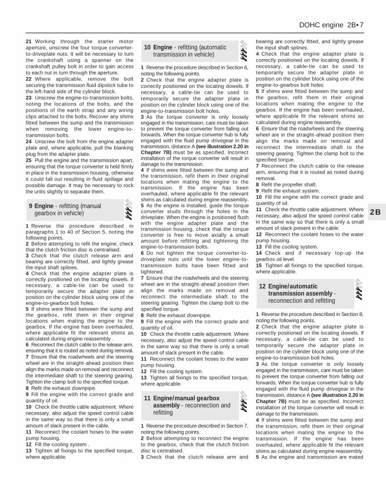
1 Reverse the procedure described inparagraphs 1 to 40 of Section 5, noting thefollowing points.2 Before attempting to refit the engine, checkthat the clutch friction disc is centralised.3 Check that the clutch release arm andbearing are correctly fitted, and lightly greasethe input shaft splines.4 Check that the engine adapter plate iscorrectly positioned on the locating dowels. Ifnecessary, a cable-tie can be used totemporarily secure the adapter plate inposition on the cylinder block using one of theengine-to-gearbox bolt holes.5 If shims were fitted between the sump andthe gearbox, refit them in their originallocations when mating the engine to thegearbox. If the engine has been overhauled,where applicable fit the relevant shims ascalculated during engine reassembly .6 Reconnect the clutch cable to the release arm,ensuring that it is routed as noted during removal. 7 Ensure that the roadwheels and the steeringwheel are in the straight-ahead position thenalign the marks made on removal and reconnectthe intermediate shaft to the steering gearing.Tighten the clamp bolt to the specified torque.8 Refit the exhaust downpipe.9 Fill the engine with the correct grade andquantity of oil.10 Check the throttle cable adjustment. Wherenecessary, also adjust the speed control cablein the same way so that there is only a smallamount of slack present in the cable.11 Reconnect the coolant hoses to the waterpump housing.12 Fill the cooling system . 13 Tighten all fixings to the specified torque,where applicable.
1 Reverse the procedure described in Section 6,noting the following points.2 Check that the engine adapter plate iscorrectly positioned on the locating dowels. Ifnecessary, a cable-tie can be used totemporarily secure the adapter plate inposition on the cylinder block using one of theengine-to-transmission bolt holes.3 As the torque converter is only looselyengaged in the transmission, care must be takento prevent the torque converter from falling outforwards. When the torque converter hub is fullyengaged with the fluid pump drivegear in thetransmission, distance A (see illustration 2.20 inChapter 7B) must be as specified. Incorrectinstallation of the torque converter will result indamage to the transmission.4 If shims were fitted between the sump andthe transmission, refit them in their originallocations when mating the engine to thetransmission. If the engine has beenoverhauled, where applicable fit the relevantshims as calculated during engine reassembly.5 As the engine is installed, guide the torqueconverter studs through the holes in thedriveplate. When the engine is positioned flushwith the engine adapter plate and thetransmission housing, check that the torqueconverter is free to move axially a smallamount before refitting and tightening theengine-to-transmission bolts.6 Do not tighten the torque converter-to-driveplate nuts until the lower engine-to-transmission bolts have been fitted andtightened.7 Ensure that the roadwheels and the steeringwheel are in the straight-ahead position thenalign the marks made on removal andreconnect the intermediate shaft to thesteering gearing. Tighten the clamp bolt to thespecified torque.8 Refit the exhaust downpipe.9 Fill the engine with the correct grade andquantity of oil.10 Check the throttle cable adjustment. Wherenecessary, also adjust the speed control cablein the same way so that there is only a smallamount of slack present in the cable.11 Reconnect the coolant hoses to the waterpump housing.12 Fill the cooling system. 13 Tighten all fixings to the specified torque,where applicable.
1 Reverse the procedure described in Section 7,noting the following points.2 Before attempting to reconnect the engineto the gearbox, check that the clutch frictiondisc is centralised.3 Check that the clutch release arm and
bearing are correctly fitted, and lightly greasethe input shaft splines.4 Check that the engine adapter plate iscorrectly positioned on the locating dowels. Ifnecessary, a cable-tie can be used totemporarily secure the adapter plate inposition on the cylinder block using one of theengine-to-gearbox bolt holes.5 If shims were fitted between the sump andthe gearbox, refit them in their originallocations when mating the engine to thegearbox. If the engine has been overhauled,where applicable fit the relevant shims ascalculated during engine reassembly.6 Ensure that the roadwheels and the steeringwheel are in the straight-ahead position thenalign the marks made on removal andreconnect the intermediate shaft to thesteering gearing. Tighten the clamp bolt to thespecified torque.7 Reconnect the clutch cable to the releasearm, ensuring that it is routed as noted duringremoval. 8 Refit the propeller shaft.9 Refit the exhaust system.10 Fill the engine with the correct grade andquantity of oil.11 Check the throttle cable adjustment. Wherenecessary, also adjust the speed control cablein the same way so that there is only a smallamount of slack present in the cable.12 Reconnect the coolant hoses to the waterpump housing.13 Fill the cooling system. 14 Check and if necessary top-up thegearbox oil level.15 Tighten all fixings to the specified torque,where applicable.
1 Reverse the procedure described in Section 8,noting the following points.2 Check that the engine adapter plate iscorrectly positioned on the locating dowels. Ifnecessary, a cable-tie can be used totemporarily secure the adapter plate inposition on the cylinder block using one of theengine-to-transmission bolt holes.3 As the torque converter is only looselyengaged in the transmission, care must be takento prevent the torque converter from falling outforwards. When the torque converter hub is fullyengaged with the fluid pump drivegear in thetransmission, distance A (see illustration 2.20 inChapter 7B) must be as specified. Incorrectinstallation of the torque converter will result indamage to the transmission.4 If shims were fitted between the sump andthe transmission, refit them in their originallocations when mating the engine to thetransmission. If the engine has beenoverhauled, where applicable fit the relevantshims as calculated during engine reassembly.5 As the engine and transmission are mated
12 Engine/automatictransmission assembly -reconnection and refitting
11 Engine/manual gearboxassembly - reconnection andrefitting
10 Engine - refitting (automatictransmission in vehicle)
9 Engine - refitting (manualgearbox in vehicle)
DOHC engine 2B•7
2B
together, guide the torque converter studsthrough the holes in the driveplate. When theengine is positioned flush with the engineadapter plate and the transmission housing,check that the torque converter is free to moveaxially a small amount before refitting andtightening the engine-to-transmission bolts.6 Do not tighten the torque converter-to-driveplate nuts until the lower engine-to-transmission bolts have been fitted andtightened.7 Ensure that the roadwheels and the steeringwheel are in the straight-ahead position thenalign the marks made on removal andreconnect the intermediate shaft to thesteering gearing. Tighten the clamp bolt to thespecified torque.8 Reconnect the selector rod and adjust asdescribed in Chapter 7, Part B.9 Refit the propeller shaft.10 Refit the exhaust system.11 Fill the engine with the correct grade andquantity of oil.12 Check the throttle cable adjustment. Wherenecessary, also adjust the speed control cablein the same way so that there is only a smallamount of slack present in the cable.13 Reconnect the coolant hoses to the waterpump housing.14 Fill the cooling system. 15 Check and if necessary top-up thetransmission fluid level.16 Tighten all fixings to the specified torque,where applicable.
Proceed as described in Part A, Section 23of this Chapter but note that on certainmodels, it may be necessary to unbolt theengine mounting brackets from the cylinderblock to allow sufficient clearance to removethe mountings.
1 Refer to Part A, Section 8 of this Chapter,paragraphs 1 to 8 inclusive.2 A selection of splined and Torx sockets willbe required to remove many of the bolts whendismantling the engine.3 Before dismantling the main enginecomponents, the following externally mountedancillary components can be removed.a) Inlet manifold (and carburettor, where
applicable).b) Exhaust manifold.c) Alternator.d) Water pump, and thermostat.e) Water pump/alternator drivebelt tensioner.f) Distributor cap, HT leads and spark plugs.g) Oil pressure warning lamp switch.h) Crankshaft speed/position sensor.i) Oil filter.j) Dipstick.k) Engine mounting brackets (if not already
done).l) Crankcase ventilation pipe and hoses.
m) Clutch.n) Alternator mounting bracket.o) Air conditioning compressor mounting
bracket (where applicable).p) Engine lifting brackets.
Note: A puller will be required to remove thecrankshaft pulley. A new crankshaft pulley bolt,a new timing chain tensioner plungerassembly, new upper and lower timing chaincover gaskets and a new camshaft covergasket and reinforcing sleeve sealing ringsmust be used on refitting.1 If the engine is in the car, carry out the
following operations.a) Disconnect the battery negative lead.b) To improve access, remove the radiator. It
will be difficult to remove the crankshaftpulley with the radiator in place.
c) On carburettor models, remove the aircleaner.
d) On fuel-injection models, remove the airinlet hose, plenum chamber and aircleaner lid as an assembly.
e) Disconnect the breather hose from thecamshaft cover.
f) Remove the distributor cap and HT leads,and the rotor arm and housing.
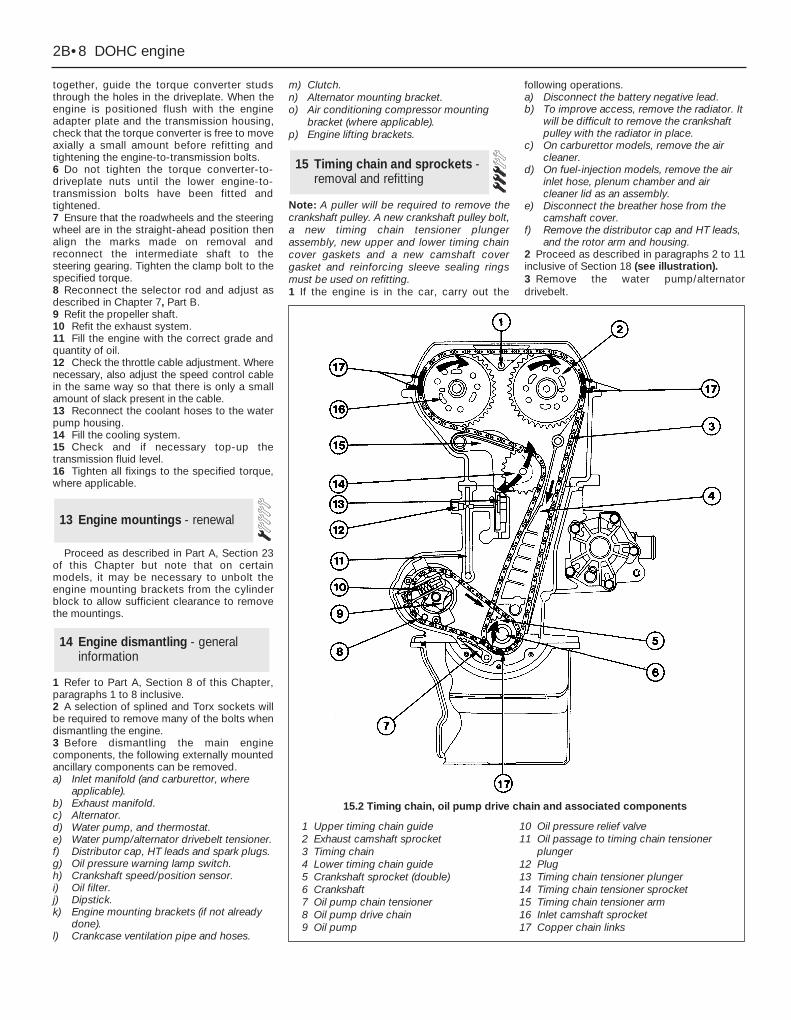
2 Proceed as described in paragraphs 2 to 11inclusive of Section 18 (see illustration).3 Remove the water pump/alternatordrivebelt.
15 Timing chain and sprockets -removal and refitting
14 Engine dismantling - generalinformation
13 Engine mountings - renewal
2B•8 DOHC engine
1 Upper timing chain guide2 Exhaust camshaft sprocket3 Timing chain4 Lower timing chain guide5 Crankshaft sprocket (double)6 Crankshaft7 Oil pump chain tensioner8 Oil pump drive chain9 Oil pump
10 Oil pressure relief valve11 Oil passage to timing chain tensioner
plunger12 Plug13 Timing chain tensioner plunger14 Timing chain tensioner sprocket15 Timing chain tensioner arm16 Inlet camshaft sprocket17 Copper chain links
15.2 Timing chain, oil pump drive chain and associated components
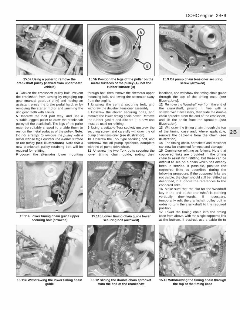
4 Slacken the crankshaft pulley bolt. Preventthe crankshaft from turning by engaging topgear (manual gearbox only) and having anassistant press the brake pedal hard, or byremoving the starter motor and jamming thering gear teeth with a lever.5 Unscrew the bolt part way, and use asuitable legged-puller to draw the crankshaftpulley off the crankshaft. The legs of the pullermust be suitably shaped to enable them torest on the metal surfaces of the pulley. Note:Do not attempt to remove the pulley with apuller whose legs contact the rubber surfaceof the pulley (see illustrations). Note that anew crankshaft pulley retaining bolt will berequired for refitting.6 Loosen the alternator lower mounting
through-bolt, then remove the alternator uppermounting bolt, and swing the alternator awayfrom the engine.7 Unscrew the central securing bolt, andwithdraw the drivebelt tensioner assembly.8 Unscrew the eleven securing bolts, andremove the lower timing chain cover. Removethe rubber gasket and discard it; a new onemust be used on refitting.9 Using a suitable Torx socket, unscrew thesecuring screw, and carefully withdraw the oilpump chain tensioner (see illustration).10 Unscrew the Torx type securing bolt, andwithdraw the oil pump sprocket, completewith the oil pump drive chain.11 Unscrew the two Torx bolts securing thelower timing chain guide, noting their
locations, and withdraw the timing chain guidethrough the top of the timing case (seeillustrations).12 Remove the Woodruff key from the end ofthe crankshaft, prising it free with ascrewdriver if necessary, then slide the doublechain sprocket from the end of the crankshaft,and lift the chain from the sprocket (seeillustration).13 Withdraw the timing chain through the topof the timing case and, where applicable,remove the cable-tie from the chain (seeillustration).14 The timing chain, sprockets and tensionercan now be examined for wear and damage.15 Commence refitting as follows. Note thatcoppered links are provided in the timingchain to assist with refitting, but these can bedifficult to see on a chain which has alreadybeen in service. If possible, position thecoppered links as described during thefollowing procedure. If the coppered links arenot visible, the chain should still be refitted asdescribed, but ignore the references to thecoppered links.16 Make sure that the slot for the Woodruffkey in the end of the crankshaft is pointingvertically downwards. If necessary,temporarily refit the crankshaft pulley bolt inorder to turn the crankshaft to the requiredposition.17 Lower the timing chain into the timingcase from above, with the single coppered linkat the bottom. If desired, use a cable-tie to
DOHC engine 2B•9
2B
15.5a Using a puller to remove thecrankshaft pulley (viewed from underneath
vehicle)
15.5b Position the legs of the puller on themetal surfaces of the pulley (A), not the
rubber surface (B)
15.9 Oil pump chain tensioner securingscrew (arrowed)
15.12 Sliding the double chain sprocketfrom the end of the crankshaft
15.11a Lower timing chain guide uppersecuring bolt (arrowed)
15.13 Withdrawing the timing chain throughthe top of the timing case
15.11b Lower timing chain guide lowersecuring bolt (arrowed)
15.11c Withdrawing the lower timing chainguide

prevent the chain from dropping into thetiming case, as during removal.18 Locate the double chain sprocket looselyover the end of the crankshaft (larger sprocketnearest the crankcase), with the timing markpointing vertically down.19 Fit the chain over the inner, largersprocket, aligning the coppered link in thechain with the timing mark on the sprocket(see illustration).20 Coat the threads of the lower timing chainguide lower securing bolt with a suitablethread-locking compound.21 Introduce the lower timing chain guidethrough the top of the timing case,manipulating the chain around the guide asnecessary, then fit the chain guide lowersecuring bolt and tighten it finger-tight.22 Push the double chain sprocket onto thecrankshaft, engaging the notch in the sprocketwith the groove in the end of the crankshaft.23 Proceed as described in paragraphs 34 to 42of Section 18, but when fitting the chain over thecamshaft sprockets, align the timing mark oneach sprocket between the two correspondingcoppered links in the chain.24 Coat the threads of the lower timing chainguide upper securing bolt with a suitablethread-locking compound, then fit the bolt andtighten it finger-tight.25 Proceed as described in paragraphs 43 to 46of Section 18.26 Tighten the two chain guide securing boltsto the specified torque.27 Proceed as described in paragraphs 47 to 55of Section 18.28 Fit the oil pump drive chain around theouter crankshaft sprocket and the oil pumpsprocket, then refit the oil pump sprocket, andtighten the securing bolt to the specifiedtorque. If necessary, a screwdriver can beinserted through one of the holes in thesprocket to prevent it from turning as thesecuring bolt is tightened.29 Refit the oil pump drive chain tensioner,and tighten the securing bolt to the specifiedtorque.30 Refit the Woodruff key to the end of thecrankshaft.31 Inspect the oil seal in the lower timingchain cover. If the oil seal is in good condition,
the cover can be refitted as follows, but if theseal is damaged, or has been leaking, a newseal should be fitted to the cover. If necessary,carefully prise the old oil seal from the coverusing a screwdriver, and drive in the new sealusing a suitable metal tube. Make sure that theseal lip faces into the engine. Note that the oilseal should be fitted dry. Take care not todamage the timing chain cover (seeillustration).32 Fit the lower timing chain cover using anew rubber gasket (see illustration).33 Loosely refit the timing chain coversecuring bolts.34 Refit the crankshaft pulley to the end of thecrankshaft, and draw the pulley onto thecrankshaft using the original securing bolt, at thesame time centering the lower timing chain cover.35 With the lower timing chain covercentralised, and the pulley fully home on thecrankshaft, remove the old securing bolt, thenfit a new bolt.36 Tighten the new crankshaft pulley bolt tothe specified torque, in the two stages given inthe Specifications at the beginning of thisChapter. Prevent the crankshaft from turningas during removal.37 Tighten the lower timing chain coversecuring bolts to the specified torque.38 Refit the drivebelt tensioner assembly,ensuring that the lug on the rear of thetensioner bracket engages with thecorresponding hole in the cylinder block, andtighten the securing bolt.
39 Swing the alternator into position to alignthe upper mounting bolt hole with thecorresponding hole in the drivebelt tensionerassembly, then refit the upper mounting bolt,and tighten the upper bolt and the lowerthrough-bolt.40 Refit the water pump/alternator drivebelt.41 If the engine is in the vehicle, reverse theoperations described in paragraph 1 ofSection 15.42 Where applicable, refill the coolingsystem.
1 Examine all the teeth on the camshaft andcrankshaft sprockets. If the teeth are “hooked”in appearance, renew the sprockets.2 Examine the chain tensioner plasticsprocket for wear. If excessive wear is evident,the complete tensioner assembly must berenewed as the sprocket cannot be renewedindependently. Note that the tensioner plungerassembly must be renewed whenever thetiming chain is removed.3 Examine the timing chain for wear. If thechain has been in operation for a considerabletime, or if when held horizontally (rollersvertical) it takes on a deeply bowedappearance, renew it.
Note: The cylinder head must not be removedwhen the engine is warm. Refer to the note atthe beginning of the following Section beforeproceeding.1 Disconnect the battery negative lead.2 On carburettor models, remove the aircleaner.3 On fuel-injection models, remove the airinlet hose, plenum chamber, and air cleaner lidas an assembly.4 Drain the cooling system.5 Disconnect the heater coolant hose fromthe inlet manifold (see illustration).
17 Cylinder head - removal andrefitting (engine in vehicle)
16 Timing chain, sprockets andtensioner - examination andrenovation
2B•10 DOHC engine
15.19 Coppered link in timing chain alignedwith crankshaft sprocket timing mark
(arrowed)
17.5 Disconnecting the heater coolant hosefrom the inlet manifold
15.31 Fitting a new lower timing chaincover oil seal
15.32 Lower timing chain cover gasket inposition. Ensure that lug on gasket
engages with notch in cover (arrowed)

6 Disconnect the breather hose from thecamshaft cover, and unbolt the hose bracketfrom the left-hand side of the cylinder head(see illustration).7 Unscrew the securing bolt and disconnectthe earth lead from the left-hand rear of thecylinder head.8 Remove the distributor cap and HT leads,and the rotor arm and housing, as applicable.If necessary, mark the HT leads to aid refitting.9 The cylinder head can be removed eitherwith or without the manifolds and fuel rail,where applicable (it is easiest to remove thehead complete with the manifolds and fuelrail). If desired, the inlet manifold and the fuelrail can be unbolted and moved to one side,leaving the wires, hoses, pipes and cablesconnected, but care must be taken not toplace any strain on them.10 Unscrew the three securing nuts anddisconnect the exhaust downpipe from themanifold. It may be necessary to jack up thefront of the vehicle to gain access to the nuts(in which case apply the handbrake andsupport the front of the vehicle securely onaxle stands) (see “Jacking”). Discard thegasket.11 If the inlet manifold and the fuel rail (whereapplicable) are to be removed with the cylinderhead, disconnect all relevant wires, hoses,pipes and cables, otherwise, unbolt themanifold and the fuel rail, and move them toone side, ensuring that they are adequatelysupported. If the fuel rail is unbolted, beprepared for fuel spillage, and take adequatefire precautions.12 Refer to the procedure described inparagraphs 2 to 19 of Section 18 to completecylinder head removal.13 Commence refitting by referring toparagraphs 20 to 55 of Section 18, thenreverse the procedure described inparagraphs 1 to 11 of this Section, noting thefollowing points.a) Use a new gasket when reconnecting the
exhaust downpipe to the manifold.b) Ensure that the HT leads are reconnected
correctly.c) Fill the cooling system.
Note: New cylinder head bolts, a new cylinderhead gasket, a new timing chain tensionerplunger assembly, a new upper timing chaincover gasket, and a new camshaft covergasket and reinforcing sleeve sealing ringsmust be used on refitting. It is essential thatthe three smaller M8 bolts are of the latest typewith hexagonal heads, not the earlier Torx type(see illustration).1 With the manifolds removed, proceed asfollows.2 Unscrew the eleven bolts and four nuts, andremove the camshaft cover. Recover the gasket.3 Unscrew the four securing bolts and threestuds, and remove the upper timing chaincover. Note the locations of the studs to aidrefitting. 4 Using a spanner on the crankshaft pulley,turn the crankshaft to bring No 1 piston to thefiring point (TDC). With No 1 piston at the firingpoint, the timing marks on the camshaftsprockets should be pointing away from eachother, and should be approximately level withthe top edge of the cylinder head. Timingnotches are provided in the camshaftsprockets, and corresponding paint marks areprovided on the outside edges of thesprockets (see illustration). 5 Hold the inlet camshaft sprocket stationaryusing a peg spanner which engages with the
spokes of the camshaft sprocket. Unscrew thecamshaft sprocket bolt, and remove thedistributor rotor shaft (see illustration).
6 Repeat the procedure given in paragraph 5for the exhaust camshaft, but note that a spaceris fitted in place of the distributor rotor shaft.7 Squeeze the upper timing chain guidesecuring lugs together, using pliers ifnecessary, and withdraw the guide from theplate at the front of the cylinder head (seeillustration).8 Mark the position of the timing chain inrelation to the camshaft sprockets, so that thechain can be refitted in precisely its originalposition (ie, make alignment marks betweeneach sprocket and a corresponding link in thechain), then slide the camshaft sprockets fromthe camshafts. Withdraw the sprockets andlay the timing chain over the exhaust side ofthe timing case, having eliminated the slack in
18 Cylinder head - removal andrefitting (engine removed)
DOHC engine 2B•11
2B
17.6 Hose bracket bolted to cylinder head(arrowed)
18.0 Use new M8 (auxiliary) cylinder headbolts with hexagonal heads (A), not the
earlier Torx type bolts (B)
18.4 Timing mark positions with No 1cylinder at TDC
18.5 Removing the inlet camshaft sprocketbolt and the distributor rotor shaft
18.7 Upper timing chain guide securinglugs (arrowed)
If a peg spanner is not available,a tool can be made from twolengths of steel strip (one long,the other short) and three nuts
and bolts; one nut and bolt forming thepivot of a forked tool with the remainingtwo nuts and bolts at the tips of the “forks”to engage with the sprocket spokes.
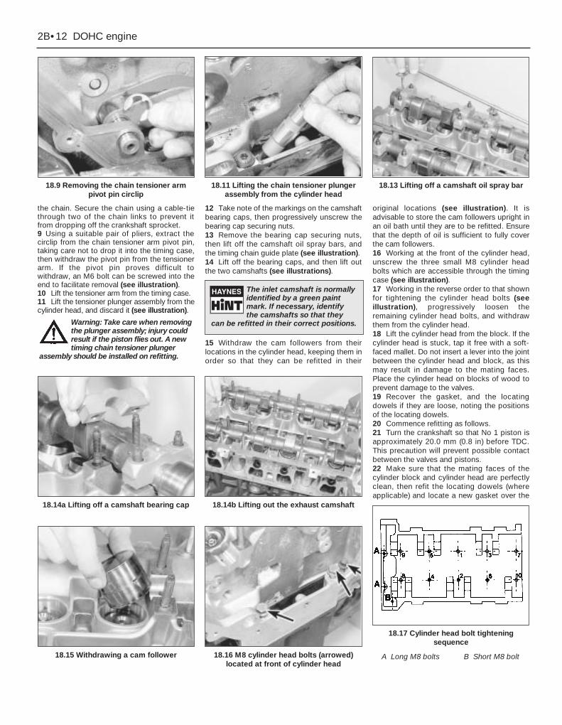
the chain. Secure the chain using a cable-tiethrough two of the chain links to prevent itfrom dropping off the crankshaft sprocket.9 Using a suitable pair of pliers, extract thecirclip from the chain tensioner arm pivot pin,taking care not to drop it into the timing case,then withdraw the pivot pin from the tensionerarm. If the pivot pin proves difficult towithdraw, an M6 bolt can be screwed into theend to facilitate removal (see illustration).10 Lift the tensioner arm from the timing case.11 Lift the tensioner plunger assembly from thecylinder head, and discard it (see illustration).
12 Take note of the markings on the camshaftbearing caps, then progressively unscrew thebearing cap securing nuts.13 Remove the bearing cap securing nuts,then lift off the camshaft oil spray bars, andthe timing chain guide plate (see illustration).14 Lift off the bearing caps, and then lift outthe two camshafts (see illustrations).
15 Withdraw the cam followers from theirlocations in the cylinder head, keeping them inorder so that they can be refitted in their
original locations (see illustration). It isadvisable to store the cam followers upright inan oil bath until they are to be refitted. Ensurethat the depth of oil is sufficient to fully coverthe cam followers.16 Working at the front of the cylinder head,unscrew the three small M8 cylinder headbolts which are accessible through the timingcase (see illustration).17 Working in the reverse order to that shownfor tightening the cylinder head bolts (seeillustration), progressively loosen theremaining cylinder head bolts, and withdrawthem from the cylinder head.18 Lift the cylinder head from the block. If thecylinder head is stuck, tap it free with a soft-faced mallet. Do not insert a lever into the jointbetween the cylinder head and block, as thismay result in damage to the mating faces.Place the cylinder head on blocks of wood toprevent damage to the valves.19 Recover the gasket, and the locatingdowels if they are loose, noting the positionsof the locating dowels.20 Commence refitting as follows.21 Turn the crankshaft so that No 1 piston isapproximately 20.0 mm (0.8 in) before TDC.This precaution will prevent possible contactbetween the valves and pistons.22 Make sure that the mating faces of thecylinder block and cylinder head are perfectlyclean, then refit the locating dowels (whereapplicable) and locate a new gasket over the
2B•12 DOHC engine
18.9 Removing the chain tensioner armpivot pin circlip
18.15 Withdrawing a cam follower
18.14a Lifting off a camshaft bearing cap
18.16 M8 cylinder head bolts (arrowed)located at front of cylinder head
18.14b Lifting out the exhaust camshaft
18.17 Cylinder head bolt tighteningsequence
A Long M8 bolts B Short M8 bolt
18.11 Lifting the chain tensioner plungerassembly from the cylinder head
18.13 Lifting off a camshaft oil spray bar
The inlet camshaft is normallyidentified by a green paintmark. If necessary, identifythe camshafts so that they
can be refitted in their correct positions.Warning: Take care when removingthe plunger assembly; injury couldresult if the piston flies out. A newtiming chain tensioner plunger
assembly should be installed on refitting.

dowels. Note that the gasket can only fit in oneposition (see illustration). Do not use jointingcompound.23 Lower the cylinder head onto the gasket,making sure that the locating dowels engage.24 Oil the threads of the new main cylinderhead bolts, and insert them into their locationsin the cylinder head.25 Tighten the bolts in the order shown (seeillustration) and in the four stages given in theSpecifications.26 Insert the three smaller M8 cylinder headbolts through the top of the timing case (seeillustration) and tighten them to the specifiedtorque. Note that new bolts must be used, andthat they should be of the latest type withhexagonal heads.27 Lubricate the cam follower bores in thecylinder head, and the cam followersthemselves, then insert the cam followers intotheir original locations in the cylinder head.28 Lubricate the camshaft bearing surfaces inthe cylinder head and the bearing caps.29 Lubricate the surfaces of the camshafts,then carefully lay the camshafts in their originalpositions in the cylinder head. Position thecamshafts with the slots in their front endspointing away from each other.30 Fit the bearing caps L1, L3, L5, R1, R3,and R5 (see illustration), then lay thecamshaft oil spray bars and the timing chainguide plate in position over the studs (seeillustrations).
31 Carefully tighten the bearing cap securingnuts by hand in the following stages to lowerthe camshafts into position.
Tighten the nuts for bearing caps L1 and R1by half-a-turn (180°)
Tighten the nuts for bearing caps L5 and R5by half-a-turn (180°)
Tighten the nuts for bearing caps L3 and R3by half-a-turn (180°)Continue to tighten the nuts in the smallstages given until the bearing caps contact thecylinder head. 32 Fit bearing caps L2, L4, R2 and R4, andtap them into position on the cylinder headusing light taps from a soft-faced mallet.Tighten the securing nuts evenly by hand.33 Tighten all the bearing cap nuts to thespecified torque in half turn stages, using thefollowing sequence.
L1 and R1L5 and R5L3 and R3L2 and L4R2 and R4
34 Fit a new chain tensioner plungerassembly to the housing in the cylinder headwith the piston uppermost. Before fitting thenew plunger assembly, take note of theposition of the piston (see illustration). Theassembly is normally supplied with the pistonprotruding slightly from the cylinder, or slightly
below the top surface of the cylinder (A). If thenew assembly is supplied with the pistonpartially unlatched (B), or fully unlatched withthe latching ring visible (C), it must not be used.
35 Locate the chain tensioner arm in position,then insert the pivot pin, and secure it with thecirclip. Take care not to drop the circlip intothe timing case.36 Release the cable-tie securing the timingchain, and lay the chain over the exhaustcamshaft sprocket, aligning the marks madepreviously on the chain and sprocket, so thatthe timing chain is taught on the exhaust sideof the engine.37 Fit the sprocket to the exhaust camshaft,with the camshaft in the TDC position (ie withthe exhaust camshaft sprocket timing mark inline with the top edge of the cylinder head,pointing to the exhaust side of the engine, seeparagraph 4). If necessary, use a pair of plierson one of the unmachined sections of thecamshaft to turn the camshaft to the TDCposition. Take care not to damage themachined surfaces of the camshaft.38 With the sprocket fitted, fit the spacer tothe end of the camshaft, and tighten thesecuring bolt finger-tight (see illustration).39 Lay the timing chain over the inlet
DOHC engine 2B•13
2B
18.22 Fitting a new cylinder head gasket 18.30a Camshaft bearing cap tighteningsequence
18.30b Camshaft oil spray bars correctlyfitted
18.30c Fitting the timing chain guide plate
18.34 Timing chain tensioner plungerassembly
A Piston retracted - plunger assembly useableB Piston partially unlatched - discard plunger
assemblyC Latching ring (1) visible - discard plunger
assembly
18.38 Spacer and sprocket securing boltfitted to end of camshaft, with camshaft in
TDC position (timing marks arrowed)
Warning: Take care wheninstalling the plunger assembly,as there is a risk of injury if thepiston flies out.

camshaft sprocket, aligning the marks madepreviously on the chain and the sprocket.40 Fit the sprocket to the inlet camshaft, withthe camshaft in the TDC position (ie with theinlet camshaft sprocket timing mark in linewith the top edge of the cylinder head,pointing to the inlet side of the engine seeparagraph 4). Again, turn the camshaft ifnecessary to enable the sprocket to be fitted.41 With the sprocket fitted, fit the distributorrotor shaft to the end of the camshaft, andtighten the securing bolt finger-tight. Note thatit is acceptable for the timing chain to sagslightly between the two pulleys. 42 Fit a new upper timing chain guide to theplate at the front of the cylinder head.43 Turn the crankshaft clockwise until theinlet camshaft begins to turn.44 If the chain tensioner plunger pistonprotrudes from the cylinder, unlatch the piston bypressing the chain tensioner arm down by hand.45 If the plunger piston is below the topsurface of the cylinder, a tool must befabricated to unlatch the piston (seeillustration). It is suggested that 2.5 mmdiameter welding rod is used to manufacturethe tool. Use the tool to release the piston asfollows.46 Carefully lift the chain tensioner arm with ascrewdriver, and insert the tool between thetensioner arm and the piston. Remove thescrewdriver, and release the piston bypressing the tensioner arm down by hand.Carefully withdraw the tool once the pistonhas been released.47 Tighten the camshaft sprocket securingbolts to the specified torque, holding thesprockets stationary as during removal.48 Turn the crankshaft clockwise through twocomplete revolutions, and check that thetiming marks on the camshaft sprockets arestill aligned with the top face of the cylinderhead as described in paragraph 4.49 Turn the crankshaft clockwise throughanother complete revolution, and check thatthe timing marks on the camshaft sprocketsare facing each other, directly in line with thetop face of the cylinder head. 50 If the timing marks do not align asdescribed, the timing chain has beenincorrectly fitted (probably one chain link away
from the correct position on one of thecamshaft sprockets), and the chain should beremoved from the sprockets and fitted in thecorrect position.51 Inspect the oil seal in the upper timingchain cover. If the oil seal is in good condition,the cover can be refitted as follows, but if theseal is damaged, or has been leaking, a newseal should be fitted to the cover. If necessary,carefully prise the old oil seal from the coverusing a screwdriver, and drive in the new sealusing a suitable metal tube. Make sure that theseal lip faces into the engine. Take care not todamage the timing chain cover.52 Fit the upper timing chain cover using anew rubber gasket. Great care must be takento avoid damage to the oil seal when passingthe seal over the end of the inlet camshaft.Careful manipulation will be required (possiblyusing a thin feeler blade) to avoid damage tothe oil seal sealing lip. Note that the oil sealshould be fitted dry.53 Refit the timing chain cover securing boltsand studs in their original locations and tightenthem to the specified torque (see illustration).54 Remove the reinforcing sleeves from thecamshaft cover, and renew the rubber sealingrings. Note that the four short reinforcingsleeves fit at the front of the cover (seeillustration).55 Refit the camshaft cover using a newgasket, and tighten the securing bolts andstuds to the specified torque.
Note: A valve spring compressor will berequired during this procedure. New valvestem oil seals should be used on reassembly.
Dismantle the cylinder head as described inparagraphs 2 to 4, Section 12, Part A of thisChapter and reassemble the head asdescribed in paragraphs 4 to 6, Section 42,Part A of this Chapter, noting the followingpoints:a) Ignore the references to the special tool.b) Double valve springs are used on all the
valves (see illustration).c) Refer to the following Section if the
cylinder head is to be inspected andrenovated.
Refer to Part A, Section 34 of this Chapter,noting the following points.a) Valve and valve seat cutting and
regrinding can be carried out usingconventional tools.
b) The cylinder head cannot be resurfaced,and if the surface distortion exceeds thespecified limits, the cylinder head must berenewed.
Note: Once the timing chain has beenremoved from the camshaft sprockets, do notturn the crankshaft until the timing chain hasbeen correctly refitted - this is to preventcontact between the valves and pistons. Anew timing chain tensioner plunger assembly,a new upper timing chain cover gasket, and anew camshaft cover and reinforcing sleevesealing rings must be used on refitting.1 If the engine is in the vehicle, carry out thefollowing operations.a) Disconnect the battery negative lead.b) On carburettor models, remove the air
cleaner.c) On fuel-injection models, remove the air
inlet hose, plenum chamber, and aircleaner lid as an assembly.
21 Camshafts and cam followers- removal, inspection andrefitting
20 Cylinder head - inspection andrenovation
19 Cylinder head - dismantlingand reassembly
2B•14 DOHC engine
18.45 Fabricated tool used to unlatchtensioner plunger piston
19.1 Withdrawing the double valve springsfrom the cylinder head
18.53 Upper timing chain cover securingstud locations (arrowed)
18.54 Fitting a camshaft cover reinforcingsleeve and sealing ring

d) Disconnect the breather hose from thecamshaft cover.
e) Remove the distributor cap and HT leads,and the rotor arm and housing. Ifnecessary, mark the HT leads to aidrefitting.
2 Proceed as described in paragraphs 2 to 15inclusive of Section 18.3 Examine the surfaces of the camshaftjournals and lobes and the contact surfaces ofthe cam followers for wear. If wear isexcessive, considerable noise would havebeen noticed from the top of the engine whenrunning, and new camshafts and followersmust be fitted. It is unlikely that this level ofwear will occur unless a considerable mileagehas been covered. Note that the cam followerscannot be dismantled for renewal of individualcomponents.4 Check the camshaft bearing surfaces in thecylinder head and the bearing caps for wear. Ifexcessive wear is evident, the only course ofaction available is to renew the cylinder headcomplete with bearing caps.5 Check the cam follower bores in thecylinder head for wear. If excessive wear isevident, the cylinder head must be renewed.6 Check the cam follower oil grooves and theoil ports in the cylinder head for obstructions.7 Refit the cam followers and the camshafts asdescribed in paragraphs 27 to 55 of Section 18.8 If the engine is in the vehicle, reverse theoperations given in paragraph 1.
Refer to Part A, Section 15 of this Chapter,noting the following points.a) If the engine is in the car, refer to Chapter
6 when removing and refitting the clutch,where applicable.
b) The flywheel/driveplate securing boltsmust be renewed on refitting; the newbolts are supplied ready-coated withthread-locking compound (seeillustration).
c) Check on the availability of new partsbefore contemplating renewal of the ringgear.
Note: A suitable puller will be required toremove the crankshaft pulley. A newcrankshaft pulley bolt and a new lower timingchain cover gasket must be used on refitting.1 The crankshaft front oil seal is located in thelower timing chain cover.2 If the engine is in the car, carry out thefollowing operations.a) Disconnect the battery negative lead.b) To improve access, remove the radiator. It
will be difficult to remove the crankshaftpulley with the radiator in place.
c) On fuel-injection models, remove the airinlet hose, plenum chamber, and aircleaner lid as an assembly.
3 Proceed as described in paragraphs 3 to 8of Section 15.4 With the lower timing chain cover removed,prise the old oil seal from the cover using ascrewdriver, and drive in the new seal using asuitable metal tube. Make sure that the seal lipfaces into the engine. Take care not todamage the timing chain cover. Note that theseal should be fitted dry.5 Refit the lower timing chain cover asdescribed in paragraphs 32 to 40 of Section 15.6 If the engine is in the vehicle, reverse theoperations given in paragraph 2.
Note: New flywheel/driveplate bolts must beused on refitting.1 Remove the flywheel/driveplate and theengine adapter plate.2 Extract the seal using an oil seal removal toolif available. It may also be possible to removethe oil seal by drilling the outer face and usingself-tapping screws and a pair of grips.3 Clean the oil seal housing, then carefullywind a thin layer of tape around the edge ofthe crankshaft to protect the oil seal lip as theseal is installed.4 Install a new oil seal. Make sure that the seallip faces into the engine (see illustration).
5 With the oil seal installed, carefully pull thetape from the edge of the crankshaft.6 Refit the engine adapter plate and theflywheel/driveplate.
Note: A new sump gasket will be required onrefitting, and suitable sealing compound willbe required to coat the sump and cylinderblock mating faces. Shims may be requiredwhen mating the gearbox/transmission.1 Sump removal and refitting is far easier ifthe engine is removed from the vehicle,however if the engine is in the vehicle, proceedas follows. If the engine has been removedfrom the vehicle, proceed to paragraph 9.2 Remove the clutch or automatictransmission, as applicable.3 Remove the flywheel/driveplate and theengine adapter plate.4 Drain the engine oil into a suitable container.5 Ensure that the steering wheel is positionedin the straight-ahead position then, using adab of paint or a marker pen, make alignmentmarks between the intermediate shaft lowerclamp and steering gear pinion. Slacken andremove the lower clamp bolt then disconnectthe intermediate shaft from the steering gear.6 Attach a suitable hoist to the engine liftingbrackets located at the front and rear of thecylinder head, and carefully take the weight ofthe engine.7 Detach the brake lines from the frontsuspension crossmember.8 Support the crossmember with a jack, thenloosen the bolts securing the crossmember tothe underbody. Remove the bolts and carefullylower the crossmember sufficiently to allowthe sump to be removed.9 If the engine has been removed, it ispreferable to keep it upright until the sump hasbeen removed to prevent sludge from enteringthe engine internals.10 Unscrew the sump securing nuts andbolts, and withdraw the sump from the engine.Do not prise between the mating faces of thesump and cylinder block. Discard the oldgasket.
11 Thoroughly clean the mating faces of thecylinder block and sump.12 Commence refitting by locating a newgasket in the grooves in the sump.
25 Sump - removal and refitting
24 Crankshaft rear oil seal -renewal
23 Crankshaft front oil seal -renewal
22 Flywheel/driveplate - removalinspection and refitting
DOHC engine 2B•15
2B
22.1 Improvised tool used to hold flywheelwhen tightening securing bolts
24.4 Tool used to fit the oil sealA Rear oil seal housingB Special tool
A tool can be improvised usinga metal tube, a metal disc orflat bar, and two flywheelbolts. Draw the seal into
position using the two flywheel bolts.
If the sump is stuck, gentlytap it sideways to free it (thesump will not move farsideways, as it locates on
studs in the cylinder block).

13 Apply a sealing compound to the faces ofthe cylinder block and sump at the pointsindicated (see illustration).14 Apply suitable thread-locking compoundto the sump securing studs and bolts, thenlocate the sump on the cylinder block and fitthe securing nuts and bolts, but do not fullytighten them at this stage.15 Align the sump so that the end faces andthe cylinder block are flush. To do this, use astraight-edge. If the sump cannot bepositioned so that the faces of the cylinderblock and sump are flush, measure thedifference in height using a feeler blade asshown (see illustration).16 Tighten the sump securing nuts and boltsto the specified torque, then repeat themeasurement made in paragraph 15. If theend faces of the sump and cylinder block arenot flush, suitable shims must be fitted(available from a Ford dealer) between thesump and the gearbox/transmission toeliminate the clearance when mating theengine to the gearbox/transmission. Note thatshims should be fitted at both sides of thesump, as required. Select suitable shims fromthose listed in the following table.
Clearance measured Shims required0 to 0.25 mm No shims required0.25 to 0.29 mm 0.15 mm (silver)0.30 to 0.44 mm 0.30 mm (light blue)0.45 to 0.59 mm 0.45 mm (red)0.60 to 0.75 mm 0.60 mm (black)
17 If the engine is in the vehicle, reverse theprocedure described in paragraphs 3 to 8,noting the following points.a) Ensure that the roadwheels and the
steering wheel are in the straight-ahead
position then align the marks made onremoval and reconnect the intermediateshaft to the steering gear. Tighten theclamp bolt to the specified torque.
b) Fill the engine with the correct grade andquantity of oil.
c) Refit the engine adapter plate and theflywheel/driveplate.
d) Refit the gearbox or automatictransmission, as applicable, ensuring thatthe required shims are fitted between thesump and the gearbox/transmission.
e) Tighten all fixings to the specified torquewhere applicable.
Note: A suitable puller will be required toremove the crankshaft pulley. A newcrankshaft pulley bolt, a new lower timingchain cover gasket and a new oil pump gasketmust be used on refitting.1 If the engine is in the car, carry out thefollowing operations.a) Disconnect the battery negative lead.b) To Improve access, remove the radiator. It
will be difficult to remove the crankshaftpulley with the radiator in place.
c) On fuel-injection models, remove the airinlet hose, plenum chamber and aircleaner lid as an assembly.
2 Proceed as described in paragraphs 3 to 10of Section 15.
3 Unscrew the four securing bolts andwithdraw the oil pump from the cylinder block(see illustration). Recover the gasket anddiscard it.4 If desired, the pump can now be dismantledand inspected.5 Thoroughly clean the mating faces of thepump and the cylinder block.6 Prime the pump by injecting clean engine oilinto it and turning it by hand.7 Place a new gasket on the oil pump flange,ensuring that the gasket is correctly located sothat the holes align with the oil passages in thepump.8 Fit the oil pump, and tighten the securingbolts to the specified torque.9 Proceed as described in paragraphs 28 to 40of Section 15.10 If the engine is in the vehicle, reverse theoperations described in paragraph 1.
1 The oil pump can be dismantled forcleaning, but if any of the components areworn, the pump must be renewed as anassembly.2 To dismantle the pump, proceed as follows.3 Unscrew the two securing bolts, andremove the pump cover (see illustration).4 Lift the inner and outer rotors from thepump casing.5 Unscrew the pressure relief valve plug from
27 Oil pump - dismantling,inspection and reassembly
26 Oil pump - removal andrefitting
2B•16 DOHC engine
25.13 Apply sealing compound to thesump/cylinder block mating faces at the
points indicated (2)Dimensions are for guidance only
27.3 Removing the oil pump cover 27.5a Unscrew the pressure relief valveplug and washer . . .
25.15 Measuring the clearance between thecylinder block and sump end faces
26.3 Oil pump securing bolts (arrowed)

the pump cover, recover the washer, andwithdraw the spring and plunger (seeillustrations).6 Thoroughly clean all components in petrolor paraffin, and wipe dry using a non-fluffy rag.7 Examine the rotors and the pump casing forsigns of excessive wear on the machinedsurfaces. If wear is evident, the completepump assembly must be renewed, as spareparts are not available individually. 8 Commence reassembly by lubricating therelief valve plunger. Fit the plunger and thespring, and screw the plug into place, ensuringthat the washer is in place under the plug.9 Lubricate the rotors, and fit them to thepump casing with the punch marks facing thepump cover (see illustration).10 Refit the pump cover and tighten thesecuring bolts.11 Prime the pump before refitting.
1 Examine all the teeth on the sprockets. If theteeth are “hooked” in appearance, renew thesprockets.2 Examine the chain tensioner for wear andrenew it if necessary.3 Examine the chain for wear. If it has been inoperation for a considerable time, or if whenheld horizontally (rollers vertical) it takes on adeeply bowed appearance, renew it.
Note: New connecting rod bolts and a new oilpick-up pipe gasket must be used on refitting.1 Remove the sump and the cylinder head.2 Unscrew the two securing bolts, andremove the oil pick-up pipe (see illustration).Recover the gasket and discard it.3 Unscrew the four securing nuts andwithdraw the oil baffle from the studs on themain bearing caps (see illustration).4 Removal is as described in Part A, Section 21,paragraphs 2 to 5 of this Chapter, and refittingas described in Part A, Section 37, noting thefollowing additional points:a) Take note of the orientation of the bearing
shells during dismantling, and ensure thatthey are fitted correctly during reassembly.
b) When fitting the pistons, ensure that thearrow on the piston crown and the letter Fon the face of the connecting rod arepointing towards the front of the engine.
c) Use new connecting rod bolts onreassembly; before fitting, oil the threadsand the contact faces of the bolts. Tightenthe bolts to the three stages given in theSpecifications.
d) Refit the oil baffle and tighten the securingnuts.
e) Clean the mating faces of the cylinderblock and the oil pick-up pipe, and refitthe pick-up pipe using a new gasket.
f) Refit the cylinder head and the sump.
Note: A new crankshaft rear oil seal and a newrear oil seal housing gasket should be used onreassembly.1 With the engine removed from the vehicle,remove the timing chain and crankshaftsprocket, and the flywheel/driveplate.2 Remove the pistons and connecting rods. Ifno work is to be done on the pistons andconnecting rods, there is no need to push thepistons out of the cylinder bores.3 Unbolt the crankshaft rear oil seal housingand remove it from the rear of the cylinderblock. Recover the gasket and discard it.4 Unscrew the two securing bolts and removethe sump mounting plate from the front of thecylinder block (see illustration).5 Check the main bearing caps for identificationmarks, and if necessary use a centre punch toidentify them (see illustration).6 Before removing the crankshaft, check thatthe endfloat is within the specified limits byinserting a feeler blade between the centrecrankshaft web and one of the thrustwashers(the thrustwashers are fitted to the crankcase,not the bearing cap). This will indicate whetheror not new thrustwashers are required.7 Unscrew the bolts and tap off the mainbearing caps complete with bearing shells.8 Lift the crankshaft from the cylinder block,and remove the rear oil seal if it is still in placeon the crankshaft.
30 Crankshaft and main bearings- removal and refitting
29 Pistons and connecting rods- removal and refitting
28 Oil pump drive chain andsprockets - examination andrenovation
DOHC engine 2B•17
2B
27.5b . . . and withdraw the spring andplunger
27.9 The punch marks (arrowed) on the oilpump rotors must face the pump cover
29.2 Removing the oil pick-up pipe
29.3 Withdrawing the oil baffle 30.4 Unscrewing a sump mounting platesecuring bolt
30.5 Main bearing cap identification mark(arrowed)

9 Extract the bearing shells, and recover thethrustwashers, keeping them identified forlocation.10 The crankshaft and bearings can beexamined and if necessary renovated.11 Commence refitting as follows (seeillustration).12 Wipe the bearing shell locations in thecrankcase, and the crankshaft journals with asoft non-fluffy rag.13 If the old main bearing shells are to berenewed (not to do so is a false economy,unless they are virtually new) fit the five upperhalves of the main bearing shells to theirlocations in the crankcase.14 Fit the thrustwashers to the centre mainbearing location, using a little grease to retainthem if necessary. The oil grooves in thethrustwashers must face outwards (ie facingthe crankshaft webs). Note that wherestandard thrustwashers have been fitted inproduction, the centre main bearing isunmarked, but if oversize (0.38 mm)thrustwashers have been fitted, the centremain bearing will carry a yellow paint mark.15 Lubricate the crankshaft journals and theupper and lower main bearing shells withclean engine oil, then carefully lower thecrankshaft into the crankcase.16 Lubricate the crankshaft main bearingjournals again, and then fit the main bearing capsin their correct locations, with the arrows on thecaps pointing towards the front of the engine.17 Fit the main bearing cap bolts, noting thatthe studded bolts secure bearing caps Nos 3and 5.18 Lightly tighten all the securing bolts, thenprogressively tighten all bolts to the specifiedtorque.19 Check that the crankshaft rotates freely.Some stiffness is to be expected with new
components, but there must be no tight spotsor binding.20 Check that the crankshaft endfloat iswithin the specified limits by inserting a feelerblade between the centre crankshaft web andthe thrustwashers.21 Refit the sump mounting plate to the frontof the cylinder block, and tighten the securingbolts to the specified torque.22 Carefully wind a thin layer of tape aroundthe rear edge of the crankshaft to protect theoil seal lips as the rear oil seal is installed.23 Refit the crankshaft rear oil seal housing,using a new gasket, and tighten the securingbolts to the specified torque.24 Install the new oil seal with reference toSection 24.25 With the oil seal installed, carefully pull thetape from the edge of the crankshaft.26 Refit the pistons and connecting rods asdescribed previously in this Chapter.27 Refit the flywheel/driveplate, and thetiming chain and crankshaft sprocket.
Proceed as described in Part A, Section 27of this Chapter, noting that the productionbearing undersizes are indicated as follows.Yellow or red paint marks on crankshaft —
standard diameter main bearing journals.Green line on crankshaft front counterweight
— main bearing journals 0.25 mmundersize.
Green spot on counterweight — big-endbearing journals 0.25 mm undersize.
Refer to Part A, Section 25 of this Chapter,but note that the connecting rod bolts shouldbe renewed on reassembly, and whenrenewing the cylinder head bolts, the latesttype bolts with hexagonal heads shouldalways be used.
Proceed as described in Part A, Section 35of this Chapter, noting the following points.a) If the cylinder head has been removed,
pay particular attention to the note at thebeginning of Section 18.
b) If removed during any dismantlingoperations, new flywheel driveplate boltsand connecting rod bolts must be used.
c) After reassembling the main enginecomponents, refer to paragraph 3 ofSection 14 and refit the ancillarycomponents listed.
Refer to Part A, Section 51 of this Chapter,but note that when the engine is first started, ametallic tapping noise may be heard. This isdue to the timing chain tensioner plungerassembly taking time to pressurize with oil,resulting in a temporarily slack chain. Thenoise should stop after a short time, once oilpressure has built up.
1 When engine performance is down, or ifmisfiring occurs which cannot be attributed tothe ignition or fuel system, a compression testcan provide diagnostic clues. If the test isperformed regularly it can give warning oftrouble before any other symptoms becomeapparent. 2 The engine must be at operatingtemperature, the battery must be fully chargedand the spark plugs must be removed. Theservices of an assistant will also be required.3 Disable the ignition system by dismantlingthe coil LT feed. Fit the compression tester toNo 1 spark plug hole. (The type of tester whichscrews into the spark plug hole is to bepreferred.)4 Have the assistant hold the throttle wideopen and crank the engine on the starter.Record the highest reading obtained on thecompression tester.5 Repeat the test on the remaining cylinders,recording the pressure developed in each.6 Desired pressures are given in theSpecifications. If the pressure in any cylinderis low, introduce a teaspoonful of clean engineoil into the spark plug hole and repeat the test.7 If the addition of oil temporarily improvesthe compression pressure, this indicates thatbore or piston wear was responsible for thepressure loss. No improvement suggests thatleaking or burnt valves, or a blown headgasket, may be to blame.8 A low reading from two adjacent cylinders isalmost certainly due to the head gasketbetween them having blown.9 On completion of the test, refit the sparkplugs and reconnect the coil LT feed.
35 Compression test -description and interpretation
34 Initial start-up after overhaulor major repair
33 Engine reassembly - generalinformation
32 Examination and renovation -general information
31 Crankshaft and bearings -examination and renovation
2B•18 DOHC engine
30.11 Crankshaft main bearings andassociated components
1 Bearing cap2 Thrustwasher3 Stud for oil baffle4 Identification markings5 Bearing shell without oil groove6 Bearing shell with oil groove7 Bearing seat in cylinder block