chapter 2 references
TRANSCRIPT

CHAPTER 2
REFERENCES
1. HANSEN, T.C. In fluence o f Aggregate #nd Void; onModulus o f E M it lc l ty o f C oncrete. Cement Mortar #nu cement P ** te . Journal o f th e American c o n cre te in i t i tw te . P roceed ing ; Vol 62, No. 2,Feb 196S, pp 193-216.
2 . SHAH, S .P . , WINTER, G. Ine1a»t1c Behaviour andF ra c tu re o f C oncrete, c a u w i . Wecmani*# and tw itro ^ o f crack in g 4n c o n c re te . Aci P u b lica tio n SPZO. 19W: PP 5-Z8.---------------
3 . SPOONER, B.C. The S tre ; ; -S tra 1 n R e la tio n sh ip fo rHardened Cement P a s te ; in co * p re ;* io n . Magazine of C oncrete k esearch . vo Z4, l^o. 79, 1972, pp 85-92.
4. HOMS, n w. The S treng th and Deformation o f Concreteunder SfxTt "jd ing: A Reviewi lech n ica iR eport, ho. *2. w * dement and C oncrete A ssocia tion Sept 1973, pp 1-2.
5. HANSEK, T .C ., op c l t pp 193-216.
6. ILLSTON, J .M ., OINWOOOIE, J .M ., SMITH. A.A. C oncrete .T i t t e r and M eta ls, The Nature and Behaviour ofs t ru c tu r a l M a te ria ls . In te rn a tio n a l S tudent E d itio n . Van k s t r a n d Relnhold 1979, pp 275-276.
7. HIRSCH, T . J . , Modulus o f E la s t i c i ty o f C oncreteA ffe c te d by E la s t ic Mojuii o f cem ent P a s te M atrix and A g g re g a te , kroceeaings o f th e American Concrete i n s t i t u t e , 59, 1962, p 4 2 \
8. ILLSTON, J .M ., OINWOOOIE, J .M ., SMITH, A.A. op C ltpp 94 - 95.
9. SOROKA, J . , P o rtlan d cement p as te and co n c re te . LondonMacmillan P re ss , 1979 pp 81-87.
10. SOROKA, I . , oo c l t pp 103-106.
11. HELMUTH, R.A ., AND TURK, O.M., E la s t ic Moduli ofHardened P o rtlan d Cement and T ricalcium 5,"Tlcate P a s te s , byegoslum an s t r u c tu r e o f P o rtlan d Cement P a s te a n a co n c re te . Highway Research Board, Special k ep o rt. No. 90 Washington 1966, pp 135-144.
12. F E LMAN , R . F . , AND B E AUD OI N , J . J . , M i c r o s t r u c t u r eand S t rength of Hydrated Cemenfl Sympusium on the Chemistry of Cement, Moscow 1974.

REFERENCES/CO,
13. FELDMAN. R .F ., AND SEREDA. P . J . , A N*w Model fo rHydrated C##*nt and i t * P ra c tic a l A pp lica tio n . EnginaaAng jo u rn a l , 53. WoT 9 . Id/G pp »3-5y.
14. 1LLST0W. J .N .. DINW000IE, J .M ., SMITH. A.A. op c l tpp 276.277. ------
15. SEREDA. P . J . . FELDMAN. R .F .. AND SWENSON. E .G ..E ffe c t of Sorbed Water on Some Mechanical p ro p e rtie * o f Hydra ted cement P a s ta ; and Compact*. H iywa* #eiearcfi Soard, Special Report Kb. W .-1 9 W . pp 56-73.
16. SOROKA, I . . op c l t pp 105-106.
17. ILLSTON, J .M .. e t al op c l t p 277.
16. SPOONER. D .C .. op e f t p 92.
19. AC! COMMITTEE 22*. C ontrol o f Cracking In ConcreteS tru c tu re* (AC: kziP -B di, Concrete in te rn a tio n a l Ge$tgn and C o n itru c tlo n V.2. No. 10 Oct 1980. pp 3$-76.
20. MAHER, A .. DARWIN, D .. M ortar Co n s t i tu e n t o f C oncreteIn Coa*re;*1on. Jou rnal American co n cre te i n s t i t u t e March - A pril 1932 pp 100-109.
21. ALEXANDER. M.G.. A8ER0EIND.A.. Ela*t1c1t% Of P la inConcrete and M o rt.r Specimen: in H ex u re and com prem on . ine c iv i l Engineer in soutn A frica . Vol 25. "No. 4 A pril 1983. pp 205-215.
22. H08BS. D.W.. op c l t p 1-2.
23. SWAMY. R .N ., RAO G .B .S ., Cement and Concrete ,earchPergamon P re :» 3, 413 I97T
24. DAVIS, O.E. Note; on T eft* C arried Out on MortarMl x e i . PH pp 2 "^1
25. SPOONER, D . C . , op c l t pp 85-86.
26. SABS 471 (1982) South A frican Bureau o f Standard*.P o rtlan d Cement (O rd inary , Rapid Hardening and Sulphate d e s is t in g ) . P re to r ia : SAes IW z.
27. ALEXANDER, M.G., A Lim ited Laboratory Study of theE ffe c t; on Hardened Conc r e te or a P l a l t l c l i e r and Three S u p e rp la : t lc l ;e r* . Concrete aeton No. J l 1983 pp UC?*.-------------

REFERENCES/cont.1 1 8
28. STOCK. A .F ., HANNANT, D .J . , WILLIAMS, R .I .T . , TheE ffe c t o f Aggregate C orcentrattom upon the S trength and Moau lu : o f Ei * : t i c i l y o f C oncrete . Maga/tne o f co n cre te Research: voi 31. No. 1U9 D e c k e r 1979. pp Z25-234.
Z9. PONTLANO CEMENT INSTITUTE De#fgm of Concrete Nlxei8/1 - 8/10 -------------------------------------------------
30. DAVIS. O .E ., op d t pp 2 -4 .
1 1 9
CHAPTER 3 ELASTICITY CONCRETE
3.1 BACKGROUND
S tru c tu ra l co n cre te I s norm ally sp e c if ie d In terms o f i t s c aap -esslv e s tr e n g th . The type o f aggregate Is seldom p re sc r ib e d , u n less a lig h tw e ig h t aggregate Is " t l l l z e d . From th i s lim ite d Inform ation an e s tim a te fo r th e e l a s t ic modulus o* th e co n cre te Is c a lc u la te d . This estim ated value I s used In design c a lc u la t io n s , not only fo r e l a s t i c d efoneatlons bu t a lso fo r creep d lsplaceam nts v ia a creep f a c to r . I t I s c le a r th a t the accuracy of th ese d isp lacem ents Is dependent on tr,c accuracy with which th e e l a s t i c modulus has been es tla m ted . I t I s coaaaonly accepted th a t th e e l a s t i c moduli derived from cube s tre n g th s are s u f f ic ie n t ly a ccu ra te fo r design purposes and th i s I s probably the case In th e m ajo rity o f s t r u c tu r e s . However, the e l a s t i c modulus a t a given s tre n g th Is dependent on th e c h a r a c te r i s t ic s o f the aggregate and I t has been found th a t e s tim a te s o f e l a s t i c sedu lus could p o ss ib ly be 50% In e r r o r ! .
As t r a d i t io n a l sources o f aggregate are d ep le te d , d l f f e r e n t aggregates may be used to provide co n cre tes o f adequate s tre n g th , b u t w ith lower m oduli. Over th e p a s t few decades most o f the mine dump aggregate sources o f W ltw atersrand q u a r tx l te have been exhausted . Engineers have th e re fo re focussed on a l te r n a t iv e sources o f :oncre te agg regate . Hence, I f th r d es ig n er Is aware o f any v a r ia t io n s , he could a ll* # g re a te r margins fo r swvement or s e le c t aggregates w ith g re a te r c a re . I t Is th e re fo re Im portant to c h a ra c te r is e lo ca l aggregates and cements and e s ta b l is h useab le re la t io n sh ip s fo r design In these m a te r ia ls . The
concre tes under t e s t In th is p ro je c t are a g ra n ite aggregate concre te and an a n d es lte aggregate co n c re te , w ith the g ra n ite having a lower e l a s t i c modulus than the a n d e s lte . In ch ap te r 1, r e s u l t s o f measurements of the Im portant eng ineering p ro p e rtie s of the rocks were p resen ted and an attem pt was made to c o r re la te the s t a t i c e l a s t ic modulus w ith measured dynamic m odi'll.

1 2 0
3.2 STRESS-STRAIN CURVE FOR CONCRETE
The term 'e l a t t l c m odului' 1; uniquely defined when app lied to p e r fe c t l in e a r ly M a s t ic , I s o tro p ic , hoawgeneous m a te r ia ls . C oncrete, however. Is a m ultiphase c o a fo s l te m a te r ia l . I t may be analysed as a two-phase m ate ria l c o n s is tin g of aggregate p a r t ic le s embedded In a m atrix o f cement m orta r. I f th e aggregate phase and m ortar phase a re considered to be homogeneous and I so tro p ic and I f d i r e c t In te ra c tio n between aggr ; s t f p a r t ic le s does not occur*. The assw qitlon th a t both aggregates and p as te s a re e l a s t ic Is g en e ra lly tru e fo r aggregates but no t fo r p astes*
I f th e r a t io o f d i r e c t s t r e s s to th e lo n g itu d in a l s t r a in produced i , c o n s ta n t, the co n stan t Is re Tarred to as th e 'modulus of e l a s t i c i t y ' o r Young's Modulus. C oncrete p re sen ts a problem In th i s r e s p e c t, as th e s t r e s s - s t r a ln r e la t io n s h ip Is n o n - lin e a r .The n o n - l in e a r i ty o f the s t r e s s - s t r a ln curve Is due to an I r r e v e r s ib le defoneatlon o f the co n cre te even a f t e r sh o rt loading tim es, which can be measured when the co n cre te Is unloaded.Thus, the term 'In s ta n ta n e o u s ' s t r a in r a th e r than 'e l a s t i c ' s t r a in Is probably more a p p ro p ria te . F igure 3.1 shows a ty p ic a l o b se rvation fo r a t e s t In which two successive cycles o f load were ap p lied w ith the mexlsam s t r e s s being approxim ately 6M of the concre te s tre n g th . Ine Young's modulus I s given by the slope o f th e s t r e s s - s t r a ln curves and th re e p o ss ib le cho ices a re :
a) the tangen t modulus, A, which 1s measured a t the s t r e s s
under co n s id e ra tio n . This value reduces as the s t r e s s In c re a se s . This modulus Is a use fu l measure o f the co n cre te respon e to r e la t iv e ly small ad d itio n a l s t r e s s e s
b) the I n i t i a l tangen t modulus, U, which Is th e slope oftn« tangen t to the curve a t the o r ig in . This Is the C lo sest approxim ation to a modulus of e l a s t i c i t y derived from tru ly e la s t ic response. The I n i t i a l tangen t modulus renders the h ig h est value o f s t a t i c e la s t ic

m o d u l u s . H o w e v e r , t h i s m o d u l u s I s o f l i t t l e p r a c t i c a l
s i g n i f i c a n c e s i n c e I t a p p l i e s o n l y t o s m a l l s t r e s s e s a n d
s t r a i n s . T h e d y n a m i c m o d u l u s o e l a s t i c i t y I s a
r e a s o n a b l e e s t i m a t e of t h e I n i t i a l t a n g e n t m o d u l u s ,
s i n c e I t s d e t e r m i n a t i o n I n v o l v e s o n l y s m a l l
d i s p l a c e m e n t s o f t h e m a t e r i a l .
c ) t h e s e c a n t m o d u l u s , C , w h i c h I s a m o r e p r a c t i c a l m e a s u r e
o f t h e m o d u l u s o f e l a s t i c i t y . A l l s t r a i n o ccurring a t a
g i v e n s t r e s s I s r e g a r d e d a s e l a s t i c , a n d t h u s t h e s l o p e
o f t h e s e c a n t b e t w e e n t h e o r i g i n a n d a n y p o i n t o n t h e
c u r v e w i l l g i v e t h e s e c a n t m o d u l u s f o r t h e c o r r e s p o n d i n g
ap p lied s t r e s s . T h is value a lso reduces w ith s t r e s s , b u t t o a l e s s e r e x t e n t t h a n t h e tan g en t m o d u l u s .
F i g u r e 3 . 1 s h o w s d i s t i n c t h y s te re s is l o o p s a n d a re s id u a l s t r a i n ( O X ) a f t e r u n l o a d i n g . I n a d d i t i o n , t h e s t r e s s / s t r a i n
c u r v e i s a t n o stage t r u l y l i n e a r a n d t h e a b o v e m e n t i o n e d m o d u l i
are a l l an a p p r o x i m a t i o n t o t h e rea l b e h a v i o u r o f c o n c r e t e . The n o n - l in e a r i ty b e c o m e s m o r e p r o n o u n c e d 1 f : -
a ! t h e load Is a p p l i e d m o r e s l o w l y : - t h i s allows a l a rg e rc r e e p s t r a i n t o o c c u r d u r i n g t h e t e s t , s o t h a t t h e s l o p e
o f the curve diminishes a t a l l s t r e s s l e v e l s . This e f f e c t Is reduced by more rapid load a p p l ic a t io n and I t I s found th a t the e f f e c t reduces on success ive loading cyc les* . This Is shown In f ig u re 3.1 by the g rea t ly diminished area enclosed w ith in the second h y s te re s i slo. p compared to the f i r s t . A recognised exper imental technique 1s to ex e rc ise th r specimen through severa l loading cycles before the e l a s t i c modulus i s es t im ated . I t I s a lso k n o w n t h a t t h e c r e e p r a t e d i m i n i s h e s w i t h
t i m e , b u t never the less specimens loaded In more t h a n t w o
m i n u t e s a n d l e s s t h a n f i f t e e n m i n u t e s s h o w n o
appreciab le d i f fe ren ce In t h e i r s t r e s s / s t r a i n curves*.

0 %S t ra in
F igure 3. T y p i c a l S h o r t - T e r m S t r e s s / S t r a i n C u r v e f o r C o n c r e t e ( a f t e r l l l s t o n e t

1 2 3
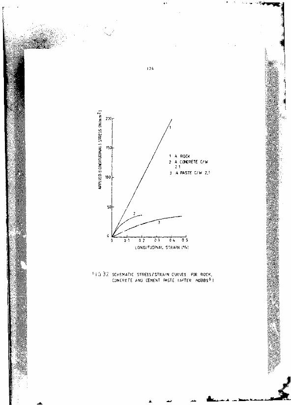
b ) t h e s t r e s s i s I n c r e a s e d t o h i g h e r l e v e l s . F i g u r e 3 . 2
s h o w s s t r e s s - s t r a l n c u r v e s f o r r o c k , c o n c r e t e a n d c e m e n t
p a s t e l o a d e d I n u n i a x i a l c o m p r e s s i o n . I n g e n e r a l , r o c k s
u s e d a s c o n c r e t e a g g r e g a t e s e x h i b i t a p p r o x i m a t e
l i n e a r i t y u p t o f a i l u r e . I n c o n t r a s t , b o t h p a s t e a n d
c o n c r e t e e x h i b i t market n o n - l i n e a r i t y . T h e n o n -
l i n e a r i t y b e c o m e s m o r e p r o n o u n c e d a t h i g h e r s t r e s s
l e v e l s , p a r t i c u l a r l y a p p r o a c h i n g f a i l u r e . T h e d e p a r t u r e
f r o m l i n e a r i t y i s g e n e r a l l y a t t r i b u t e d t o t h e
d e v e l o p m e n t o f m i c r o c r a c k i n g . T h e s e m i c r o c r a c k s s t a r t
a t r e l a t i v e l y l o w s t r e s s e s a n d m a k e a n I n c r e a s i n g
c o n t r i b u t i o n t o t h e c u r v a t u r e o f t h e s t r e s s - s t r a i n c u r v e
a s t h e s t r e s s l e v e l r i s e s . H o w e v e r , a s d i s c u s s e d i n
c h a p t e r 2 , M a h e r a n d D a r w i n * s t a t e t h a t t h e n o n -
l i n e a r i t y o f c o n c r e t e u n d e r c o m p r e s s i v e l o a d i n g I s
h i g h l y d e p e n d e n t o n t h e n o n l i n e a r i t y o f I t s c e m e n t p a s t e
a n d m o r t a r c o n s t i t u e n t s . C e m e n t m o r t a r I s n o t a n
e l a s t i c , b r i t t l e m a t e r i a l b u t I s n o n l i n e a r a n d d a m a g e d
c o n t i n u o u s l y u n d e r l o a d . T h e s e s t u d i e s s e e m t o d i m i n i s h
r . i c r o c r a c k l n g a s t h e m o s t i m p o r t a n t f a c t o r I n t h e
n o n l i n e a r b e h a v i o u r o f c o n c r e t e .
I t w o u l d t h e r e f o r e a p p e a r t h a t t h e e l a s t i c m o d u l u s f o r c o n c r e t e
s h o u l d b e q u o t e d w i t h r e f e r e n c e t o a p a r t i c u l a r r a t e o f l o a d i n g
a n d a s p e c i f i e d s t r e s s l e v e l . H o w e v e r , c a r e f u l d e f i n i t i o n a n d a
w e l l c o n s i d e r e d e x p e r i m e n t a l t e c h n i q u e c a n l e a d t o t h e
measurement o ' values th a t enable good p r e d ic t io n : to be made of Immediate s t r a i n s in concre te a f t e r loading.
3 . 3 E L A S T IC MODULUS FO R CONCRETE
The engineering des igner has a f i r s t r e s p o n s ib i l i t y to ensure t h a t h is s t r u c tu r e w il l ca r ry imposed loads; t h i s leads him to give p r i o r i t y to the ana ly s is of the s t r e s s e s in the s t ru c tu r e due to ex ternal fo rces . Concrete a lso undergoes deformation as « r e s u l t of e l a s t i c , creep , shrinkage and thermal s t r a i n s . These s t r a i n s are a f fe c te d in d i f f e r e n t ways by time dependent fac to r*
ife.
APPL
IED
ILON
GIfm
NAU
STRE
SS
IWrn
m
A POCK* CONCRETE C /W
A PASTE C/W 2,1
0 & 0 50 30 0 20 1L O S G I T U O I N A L S T R A I N ( % )
F I G 3 2 SCHEM ATIC S T R E S S fS T R A IN CURVES FOR ROCK .C O N CRET E ANO CEMENT * S T E (A FT ER H O B B S ' I

1 2 5
s u c h a s s t r e s s , r e l a t i v e h u m i d i t y a n d t e m p e r a t u r e . T h e
r e i n f o r c e d c o n c r e t e d e s i g n t e c h n i q u e s used a genera tio n ago w e r e
r e l a t i v e l y s i m p l e . T h e e l a s t i c m o d u l u s o f c o n c r e t e w a s t a k e n a s
1 5 S P a a n d t h e f a c t t h a t the ac tu a l v a l u e w a s a p p r o x i m a t e l y
d o u b l e t h i s f i g u r e e f f e c t i v e l y t o o k c a r e o f a n y s h r i n k a g e o r
c r e e p d e f o r m a t i o n f o r n o r m a l s t r u c t u r e s . H o w e v e r , t h e m o d e r n
a p p r o a c h Is t o a n a l y s e th e v a r i o u s s t r a i n c o m p o n e n t s I n s o m e
d e p t h . C a r e m u s t b e ex erc ised I n t h i s s i t u a t i o n a n d s ig h t m u s t
n o t b e l o s t o f t h e f a c t t h a t c o n cre te I s a h e t e r o g e n e o u s m a t e r i a l
a n d I t s b e h a v ' o u r c a n n o t be p r e d i c t e d w i t h c o m p l e t e a c c u r a c y .
T h # d e f le c tio n o f * co n cre te # r * b * r mmy co nven ien tly be d iv idedI n t o t h r e e c o m p o n e n t s 7 ( e x c l u d i n g t h e r m a l m o v e m e n t s ) :
1) in stan tan eo u s movement Induced by ap p lied loads
2) long term movement caused by creep
3 ) m o v e m e n t c a u s e d b y d r y i n g s h r i n k a g e
The moAjlws of e l a s t i c i t y of co n cre te I s In v a ria b ly estim ated from th e co n cre te s tre n g th as d iscu ssed l a t e r In t h i s c h a p te r . However, th i s method Ignores o th e r f a c to rs which In flu en ce e l a s t i c i t y . In p a r t i c u la r , the modulus o f e l a s t i c i t y 1s dependent upon the moduli o f e l a s t i c i t y o f th e aggregate and the cement p a s te , and upon the volume c o n cen tra tio n o f aggregate .The modulus o f e l a s t i c i t y of concre te I s used In e l a s t i c analyses and In creep c a lc u la t io n s , so I f Is Im portant th a t aggregate e l a s t i c i t y e f fe c ts a re no t to ta l ly n eg lec ted . For example, 1f a slen d er b ridge were co n s tru c ted using a high modulus aggregate as opposed to a low modulus agg reg a te , o th e r mix design p ro p e rtie s being e q u a l, d e f le c tio n s and cu rv a tu re s would be reduced.
D e n s e a g g r e g a t e s n o r m a l l y u s e d I n c o n c r e t e mixes d o n o t
e x p e r i e n c e c r e e p . H e n c e , t h e c r e e p o f c o n c r e t e Is d e t e r m i n e d b y
t h e c r e e p o f t h e c e m e n t p a s t e a n d I t s v o l u m e c o n c e n t r a t i o n . T h e
m a g n i t u d e o f c r e e p I n c r e a s e s a s p a s t e c o n t e n t I n c r e a s e s . T h e

1 Z 6
a g g r e g a t e e f f e c t i v e l y r e s t r a i n s c r e e p o f t h e o as t* , t h e ' s t l f f e r '
t h e a g g r e g a t e , t h e g r e a t e r t h e r e s t r a i n t . I t f o l l o w s t h a t f o r
t h e s a m e c e m e n t / w a t e r r a t i o a n d a g g r e g a t e c o n c e n t r a t i o n ,
co n c re te s designed w ith s o f t ' aggregates w ill e x h ib it g re a te r c r e e p t h a n t h o s e m a d e w i t h ' s t l f f e r ' a g g r e g a t e s . C r e e p o f
l i g h t w e i g h t c o n c r e t e s I s h igher t h a n t h a t o f n o r m a l w eight c o n c r e t e s o f t h e s a m e c e m e n t / w a t e r r a t i o , t h e h i g h e r c r e e p b e i n g
a t t r ib u ta b le to the lower s t i f f n e s s o f th e lig h tw eig h t agg reg a te . Various ex p ress ions have been suggested to p re d ic t co n cre te creep w i t h t i m e , i n a l l o f th ese eq u a tio n s , t h e m o d u l u s
o f e l a s t i c i t y o f t h e c o n c r e t e Is I n v o l v e d e i th e r d i r e c t l y o r
In d ire c t ly . Hence th e e l a s t i c modulus o f the aggregate which Is I n e x tr ic a b ly linked to th a t o f th e co n cre te w ill a f fe c t deform ation c a lc u la t io n s .
The co arse aggregate a lso p lays a major ro le In d e teneln lng
shrinkage movements In c e r ta in in s ta n c e s , s t ru c tu re s made w ith dubious coarse aggregate have undergone s ig n if ic a n t ly g re a te r d e f le c tio n s than those made w ith sound ag g reg a te . The c o r re la tio n between high shrinkage and low e l a s t i c modulus could
In d ic a te th a t these d e f le c tio n s may have been e rroneously a t t r ib u te d to d rying shrinkage w h ils t low e l a s t i c modulus may, In f a c t , have been the f a c to r . Hence aggregates p rev iou sly regarded as unaccep tab le may be used provided an ap p ro p ria te value of e l a s t i c modulus i s used*.
The c o n tr ib u tio n of sh rinkage to the cu rv a tu re and d e f le c tio n of a co n cre te member Is be liev ed to be somewhere between 5 and
30%9, but g re a te r shrinkage c o n tr ib u tio n s can occur I f the a p p lied bending moments are lowlO. Thus, to a s c e r ta in r e l ia b le p re d ic tio n s fo r the d e f le c tio n s o f re in fo rc e d concre te members, es tim a tio n o f shrinkage must be taken In to account. The shrinkage of p la in concre te th a t r e s u l t s from drying 1 s p rim a rily dependent upon the r e la t iv e hum idity of the a i r surrounding the co n c re te , the su rface area from which m oisture can be lo s t r e a t l v e to the volume o f the co n c re te , and the mix p ropo rtio n s o f the con cre te .
Worm! dense aggregates fo r concre te u su a lly have n e g lig ib le sh rinkages. For a p as te o f given q u a l i ty , th e shrinkage of the c o n c r e t e w i l l d e c r e a s e w i t h I n c r e a s i n g co n cen tra tio n o f
aggregate . In f a c t , th e re Is much s im i la r i ty In th e e f f e c t of aggregate on both shrinkage and creep In co n c re te . The aggregate a lso r e s t r a in s th e sh rinkage of th e p as te and hence the co n c re te . The ' s t l f f e r ' th e aggregate used, the g re a te r the reduction In shrinkage. However, In creasin g th e volume co n cen tra tio n o f the aggregate has a g re a te r e f f e c t on reducing s h r i n k a g e t h a n I n c r e a s i n g t h e r i g id i t y o f t h e a g g r e g a t e 1 1 . The shrinkage o f concre te may only be 20 p ercen t o f th a t o f cement pas te of Id e n tic a l cem ent/w ater r a t i o 1?.
The e f f e c t o f aggregate s t i f f n e s s on th e modulus o f e l a s t i c i t y and shrinkage of co n cre te Is In d ica ted In an In d ire c t way In f ig u re 3 .3 In which shrinkage Is p lo tte d a g a in s t modulus of e l a s t i c i t y of the co n c re te . I t Is ev id en t t h a t th e shrinkage depends on the modulus o f e l a s t i c i t y and d ecreases w ith Increase In I t s va lue . As s ta te d above, th e modulus o f e l a s t i c i t y depends to a la rg e degree on th a t o f the agg regate . I t fo llow s th a t the shrinkage of concre te w il l a lso depend on th e modulus o f the agg regate . Shrinkage In a lig h tw eig h t aggregate Is g re a te r than th a t o f normal w eight co n c re te . This Is supported by f ig u re 3 .3 where the shrinkage of lig h tw e ig h t co n cre te Is c le a r ly g re a te r than th a t o f nonaal-w eight c o n c re te . However, fo r both shrinkage and c reep , lig h tw e ig h t and norm al-weight concre tes of s im ila r s tre n g th e x h ib i t the same magnitude of sh rinkage1*. To o b ta in the same s tre n g th , lig h tw e ig h t concre te must be made with a h igher cem ent/w ater r a t io than norm al-weight co n cre te . The h igher cem ent/w ater r a t io reduces shrinkage In the p a s te , d e sp ite th e h igher cement co n ten t which norm ally accompanies an Increase In cem ent/w ater r a t io . T herefore , the e f fe c t of cem ent/w ater r a t i o outweighs th a t o f cement co n te n t1^.

Figure
S e c a n t m o d u l u s , k N / m m ^
3.3 Shrinkage of Concrete P lo tte d A gatn it I t ; Secant ModuTu: o f E la s t i c i ty ( a f t e r R e ic h a rd " )*. norm al-w eight co n c re te ; o , ligh tw eigh t concrete

1 2 9
F in a l ly , t h e r m a l s t r a i n o c c u r s I n c o n c r e t e . T h e c o e f f i c i e n t o f
t h e r m a l e x p a n s i o n c f c o n c r e t e Is dependent mainly u p o n t h e
c o e f f i c i e n t o f e x p a n s i o n o f t h e c e m e n t p a s t e , w h i c h I n t u r n
depends on th e m oisture c o n te n t. The c o e f f ic ie n t or th e concre te Is a lso a f fe c te d by the c o e f f ic ie n t o f expansion of the ag g reg a tes . Since the c o e f f ic ie n t o f expansion of the aggregate Is le s s than th a t o f the p a s te , th e c o e f f ic ie n t o f expansion of co n cre te w ill decrease w ith In cre ase In co n cen tra tio n of aggregate^* . Thermal s t r a in s a re c a lc u la te d from the product o f a s u i ta b le c o e f f ic ie n t o f thermal expansion and the a n tic ip a te d tem perature change.
Much of th e wort c a r r ie d o u t to d a te on th e above deform ations has been la b o ra to ry o r ie n ta te d . The c u rre n t need Is to conduct experim ental work In the f i e ld and to r e la te th e la b o ra to ry measurements to the f i e ld r e s u l t s In p r a c tic a l en g ineering term s. Table 3 .1 In d ic a te s ty p ica l s t r a in s th a t might develop between th e s t a r t o f c o n s tru c tio n and 30 y ea rs o f se rv ic e fo r a concre te w ith a Z8 day s tre n g th of 4CMPa loaded a t the age of 90 days.
3 .4 FACTORS AFFECTING MODULUS OF ELASTICITY OF CONCRETE
There r r e a number o f f a c to rs which a f f e c t the modulus of e l a s t i c i t y o f concre te e .g .
(a) Mix F ac to rs:
1) p as te cem ent/w ater r a t io (and hence s tre n g th )2) pas te p o ro sity
3) aggregate co n cen tra tio n and nature C) s t i f f n e s s o f various phases
(b) Serv ice f a c to rs :1) age of loading2) m oisture con ten t3) voids and Incomplete compaction4) tem perature e f fe c ts

no
Table 3.1 S t ra in s p red ic ted fo r a 40 MPa Concrete( a f t e r P a r r o t t 1 ' )
S t r a i n co*p@m#nt* * 10* T o ta l s t r a i n * 10*f@r a ; tr# a # of
(Im'.IWUKl «$* *0i 0 # N/m*2
.# per M/we2 *7 MO - 1*0 2*0 #0*
1# W/m** W **r W/a#2 + 210 - ? 0 t # * 2 7 0 370 to 710
^ r .
* r
a t* "
mtrmle cr*## i t r a m
m&rmlu

131
The modului o f e l a s t i c i t y 1* p r im a rily re la te d to com pressive s tre n g th and d en s ity and can be a sc e r ta in e d from em pirical eq u a tio n s . F ac to rs a f fe c tin g s tre n g th a lso a f f e c t the e l a s t ic
modulus. However, th e re are excep tions to t h i s , fo r ex aap le , two co n cre tes o f s im ila r s tre n g th made w ith d i f fe r e n t aggregates can have wp to a 50% d iffe re n c e In e l a s t i c modulus**.
3.4 .1 Aggregate
The modulus o f e l a s t i c i t y o f th e aggregate and I t s volume co n cen tra tio n both s ig n i f ic a n t ly a f f e c t th e modulus o f the c o n c re te . The modulus o f e l a s t i c i t y o f o rd inary c o n c re te , where th e aggregate I s s t l f f e r then th e p a s te . Is g r e a te r than th a t o f the p as te and In cre ases w ith In c re asin g aggregate volume co n cen tra tio n and s t i f f n e s s . When the p as te Is s t l f f e r than the ag g reg a te , th e modulus o f e l a s t i c i t y o f the co n c re te Is lower than th a t of th e p as te and decreases w ith In c re as in g co n cen tra tio n o f agg reg a te . G en era lly , th e modulus o f e l a s t i c i t y o f co n cre te In cre ases w ith In c re ase In modulus o f aggregate**.
The modulus o f e l a s t i c i t y o f co n cre te Is a lso soawwhat s e n s it iv e to t t * g rad ing , maximum s iz e and te x tu re o f the aggreg a te . The main In fluence o f these Is on th e w o rk a b l l ty o f th e co n cre te and hence on aggregate volume c o n c e n tra tio n . The *alue of the e l a s t i c modulus Is p a r t ly dependent on p ro g ress iv e m icrocrecking a t the p as te aggregate In te r f a c e . H um ver, th ese f a c to rs are secondary In r e la t io n to the modulus o f the agg reg a te , and the volume co n cen tra tio n of th agg regate .
3 .4 .Z P aste
The e l a s t ic modulus o f the hardened cement p a s te , Ep. a lso ha; a s ig n if ic a n t e f f e c t on the modulus o f the c o n c re te . The dominant param eter 1; p as te p o ro s ity and the lo d u lu s o f the

co n cre te w ill d ecrea l* markedly a ; p o ro sity in c re a se s . I .e . a ; ^em ent/w ater r a t i o d ecrease* . P o ro sity change; occur e n tire ly w ith in the p a s te , and th e re fo re change In the concrete s t r e i s - s t r a l n behav iour w ith change In cement/water r a t io Is due to changes In p a s te r e sp o n s e ^ . The e f fe c ts of the modulus of th e p a s te , Ep, m oistu re c o n te n t, movement of In te rla y e r water and th e i r r e sp e c tiv e e f fe c ts on the modulus o f e l a s t ic i t y of the c o a r -e te a re d e a l t w ith comprehensively In chap ter 2.
J .4 .3 E ffe c t o f Concrete S trength
T heore tica l eq u a tio n s used to p re d ic t the modulus o f e l a s t i c i t y o f co n cre te a re no t very p r a c t ic a l . They req u ire a knowledge of the moduli o f the c o n s titu e n t m a te r ia ls , tamely th e pas te ana the agg regate . C onsequently , In engineering p ra c tic e , the modulus is estim ated from the com pressive s tren g th o f the con cre te . As s t* te d above, f a c to r : a f fe c t in g s tre n g th o ften a f fe c t modulus In a s im ila r way, th e excep tions being th a t a h igher E* r e su lts In a h ig h e r Eg and t h i s Is no t n e c e ssa rily tru e fo r s tre n g th .Also th e w e tte r th # c o n c re te , the h igher the Eg (due to c a p i l la ry pore p re s s u re s ) , whereas an opposite e f fe c t is noted fo r s tre n g th . F igu re 3 .4 shrw* th a t p a s te modules Is re la te d to I t s s tr e n g th , and therefore h igher strength pastes w in Impart a h igher modulus to the co n cre te .
Hence, fa r th e same ag g reg a tes . I t follow s th a t the modulus of e l a s t i c i t y o f c o n c re te , Er w in se r e la te d to I t s compressive s tr e n g th , fg . An em pirica l re la t io n sh ip fo r concrete Is In th* general form
Eg ' (k . fg)% i (3 .1)
where Eg - modulus of e l a s t i c i t y of concre tek « co n s ta n t depending on s p e c if ic co nd itionsfg « com pressive stren g th of the concreten » an In te g e r (g en era lly Z or ])

Figure 3.4
o 20
110Compressive strength, Mr,m?
R ela tion between ModuTu: of E T i s t l c l t y and Compressive S trength for Cement Paste ( a f t e r Feldman and Btoudoln^l)
Aggregate p ro p e r t ie s a f f e c t co n cre te s tre n g th . The ex ac t na tu re o f th is e f f e c t Is no t always c le a r , bu t g en e ra lly speaking, concre te s tre n g th In creases w ith In crease In aggregate modulus o f e l a s t i c i t y and co n cen tra tio n and w ith decrease In I t s p a r t ic le s iz e . The s tre n g th o f o rd inary co n cre te I s only s l ig h t ly a ffe c te d by th e s tre n g th of th e a g g re g a te ^ . These f a c to r s , however, a f f e c t th e modulus o f the co n cre te to a g re a te r e x ten t than th e i r corresponding e f fe c ts on s tre n g th .
3.4.4 Service Factors
The s tru c tu re o f hardened cement p as te I s s u f f ic ie n t ly d iso rdered to ensure th a t s t r e s s - s t r a ln r e la t io n s h ip s are not sim ple. As s ta te d in se c tio n 3 .2 . the term 'In s ta n ta n e o u s ' s t r a in ra th e r than 'e l a s t i c ' s t r a in Is more a p p ro p ria te fo r co n cre te even a f t e r sh o rt load ing tim es. This Is because a p o rtio n o f th e s t r a in Is no t r e v e r s ib le , s t r a in I s time dependent and creep occu rs . P a r r o t t ^ suggests a formula to e s tim a te the e l a s t i c modulus a t time of lo ad in g , as fo llo w s:-
Et - E;g 10,4 + 0 .6 f t / f g g ) (3 .2 )
where - modulus o f e l a s t i c i t y of concre te a t age t daysEgg * 28 day modulus of e l a s t i c i t y o f concre tef^ " cube s tre n g th a t age t days fgg " 28 day cube s tren g tht - age a t loading
F urtner t x t n n s l c e f f e c t s Includ? temperature and compaction of c o n c t t t e . Monfore and Lentz^* Ind ica te th a t a t very low
*q»er&ture*. the re Is a cons iderab le Increase In the modulus of
e l a s t i c i t y of concre te . At high temperatures, however, the re Is a p rogress ive decrease In the modulus of e l a s t i c i t y ^ .Incomplete compaction a ls o a f f e c t s concre te modulus. Kaplan?* showed th a t S percen t voids can reduce th e modulus of e l a s t i c i t y of concrete by 18 per cen t .

3.5 EQUATIONS RELATING ELASTIC MODULUS OF CONCRETE AND COMPRESSIVE STRENGTH
The fo llow ing fauts should be borne In mind before the spec ific equations are stated. There I t no d ire c t theore tica l basis fo r a re la tionsh ip between the compressive strength o f the concrete and the e la s tic modulus o f the concrete. A ll such re lationsh ips are empirical and are used fo r reasons o f p ra c t ic a lity . The fo llow ing equations take no cognizance o f the a ffec ts o f age or aggregate properties. The B r it is h Standard Code of Practice fo r the S tructura l Use of Concrete, CPllO^?, and '• South African Code SA83 0 1 0 0 ^ 8 state tha t the s ta t ic moilv f e la s t ic ity Is re lated to the cube strength as f o l 1 ows:-
Eg « 9.1 (3.3)
wh*r# E; « modwlui o f e l a i t l e l t y o f co n cre te In 8P#feu * c#b* s tre n g th of co n cre te In # t time of
tm itln#
The CEB/Fip29 (1970) derive the e la s tic modulus from cy linde r compressive strength. The formula Is given by
Eg ' 6.6 (fcy)l/Z ........... (3.4)
where Ec » modulus of e la s t ic ity o f concrete In GPafey " cy lin d e r s tre n g th # t the ap p ro p ria te age In MPa
For lig h tw e ig h t co n cre te* . CEB/FIP recommend the fo llow ingequation:-
Ec " 1 .8 (p j fgy) 1 /2 ............. ( 3 . 5 )
where Eg » modulus o f e la s t ic ity of the concrete In GPa p • density of the concrete kg/nv*
fey " cy linder strength at the appropriate age In MPa

The American Concrete I n s t i t u t e base t h e f r equation on a square roo t r e la t io n s h ip r a th e r than a cube roo t . The AC I Building code 197730 gives Ec In GPa and f Cy In MPa. The equation Is
Eg ' 4.73 ( fc y ) l /Z ........ (3 .6 )
T his equation was l a t e r m odified to
Ec - 4 .9 ( fc „ ) l /Z ......... (3 .7 )
which Is based on th e cube s tre n g th feu ra th e r than th e c y lin d e r s tre n g th fgy.
O avls^l proposed a curve fo r South A frican con cre tes (see f ig u re 3 .5 ( a ) ) . The curve Is th e l in e o f b e s t f i t fo r approxim ately 100 experim en ta lly measured p o in ts . The t e s t r e s u l t s fo r a l l ages from 7 days to one y ear a re p lo t te d . He a lso showed th a t age a f fe c ts co ap resslv e s tre n g th and e l a s t i c modulus d if f e r e n t ly (see f ig u re 3 .5 (b ) ) . The c r v e s show th a t one y ear a f t e r c a s t in g , the e l a s t i c modulus I s approxim ately 15% g re a te r than a t 28 days. However, th e com pressive s tre n g th Is40% g re a te r than the corresponding value a t 28 days. Davisconsidered th a t the s c a t t e r was p r la w rlly due to the wide v a r ie ty of aggregates te s te d and mix p ro p o rtio n s used, ra th e r than the age d1 ffe ren ce .
The Cement and Concrete Associat ion (U.K.) Development Report No. 3%3 es t im ates the e l a s t i c modulus from a l i n e a r r e la t io n s h ip Incorpora ting an Index of aggregate so f tn ess ( r e l a t e d to the aggregate) and age e f f e c t s .

F I G 3
0 a t o 60 80 TOO
COMPRESSIVE STRENGTH - MPa
5 a RELATIONSHIP BETWEEN COMPRESSIVE STRENGTH AND ELASTIC MODULUS OF CONCRETE (AFTER DAVIS 31)

1 3 8
120
99%
a%
d
F IG 3 . 5 b ELASTIC MODULUS AND COMPRESSIVE STRENGTH EXPRESSED IN TERMS OF 2 8 DAY VALUE (AFTER DAVIS?")

The equation i i given in th e fo r* .
Em " c„ + 0.2 f a (3.8)
where E%g » ?8 day madulu* of concre te
f a " th e comp re s t iv e cube s tre n g th a t 28 daysC@ « fa c to r c lo se ly re la te d to th e modulus o f the
aggregate
"" tey propose th a t Co has a mean value o f ZOGPa fo r normal- w eight aggregates and 10 GPa fo r lig h tw e ig h t ag g reg a tes . The modulus o f e l a s t i c i t y of co n cre te a t ages o th e r than 28 days Is estim ated from equation (3 .2 ) quoted e a r l i e r In the t e x t . I t is a lso recoaseended th a t measured s tre n g th s be used as f a r as p o ss ib le In equation ( 3 .2 ) , as th e use of s tre n g th r a t io s
obtained from CP110 or elsew here would reduce th e r e l i a b i l i t y of the es tim ated value.
3 .6 CURRENT METHODS OF MEASURING STATIC ELASTIC MODULUS
The e l a s t i c i t y o f co n cre te may be assessed by means o f cy lin d e r and prism com pressive t e s t s and f le x u ra l beam bending t e s t s However, th e re a re d if fe re n c e s between moduli measured in these t e s t s A lexander and Aberdein^* c a r r ie d o u t a s e r ie s o f t e s ts on concre te and m ortar under coaqiresslon and f le x u re . They found e l a s t i c moduli measured <n beam t e s ts were about 6 p e r cen t h igher than prism m oduli, which In tu rn were about 7 per cen t h igher than modul1 measured In a s tandard cy lin d e r t e s t . In the case o f th e beam bending t e s t s , a c o rre c tio n fo r shear d e f le c tio n and the Seewald e f f e c t , which tak es account o f d e v ia tio n s from th e slmpln theory of bending in the f le x u ra l t e s t , were included . The beam te s ts y ie ld ed a lower spread of values fo r e l a s t ic modulus than the compression t e s t s . The spread of values fo r the c y lin d e rs and prisms were e s s e n t ia l ly the same. They p o stu la ted th a t the v a r ia t io n 1i e l a s t i c modulus of the d if fe r e n t types of

t e x t could po**1b1y be exp la ined In term : of the Wei b u ll 33 w e* k « t lin k theory fo r the s tre n g th o f m a te r ia l : . According to t i l l ; th eo ry , the p ro b a b il ity o f f a i lu r e of a specimen I : dependent on the »tre$» in the specimen, and th e volume of m ate ria l under s t r e s s . For two t e s t p ieces id e n tic a l in every re sp e c t except th a t one has a g re a te r volume of m a teria l under maximum s t r e s s than I t s c o u n te rp a r t, the theo ry in fe rs th a t th e la rg e r t e s t p iece w ill ( a i l a t a low er s t r e s s than th e sm aller L,-,3 The above argument was ap p lied to s t i f f n e s s ra th e r than s tre n g th , as i t Is known th a t I s o la te d c racks a re I n i t i a t e d in co n cre te a t a m olecular lev e l a t very low s t r e s s e s . The m ic ro stru c tu re o f co n cre te can be taken to be a l a t t i c e o f In te r l in k in g aggregate and m ortar members and th e response o f co n cre te to s t r e s s I s dependent on th e s t i f f n e s s o f th e l a t t i c e . The au tho rs s t a te th a t th e volume of th e 'a r g e r specimen hau I g re a te r p ro b a b il i ty of 's e r io u s ' In c ip ie n t c ra c k s , and hence a lower s t i f f n e s s In i t s l a t t i c e s t r u c tu r e . I t f o l1ows th a t th e la rg e r c y lin d e rs may be expected to have a low * s t i f f n e s s than th e sa w lle r prism s and beams. O ther In v e s t ig a to rs have shown th a t th e e l a s t i c modulus o f co n cre te may depend on, amongst o th e r th in g s , the s t a te v f s t r e s s In th e specimen, specimen and t e s t geometry, and environm ental c o n d i t io n s ^ .
Hoguestad e t a l^* in te s t in g orism s and c y lin d e rs o f s im ila r to ta l volume, found th a t e c c e n tr ic coap resslon c o n d itio n s gave e l a s t ic moduli 10 per cen t g re a te r than the u n iax ia l compression c o n d itio n . They a lso coaqpared f le x u ra l and compression moduli fo r concre te and found th e n t l o to be 1 ,1 ; they s ta te d the d if fe re n c e between the s t r e s s s ta te s o f f le x u re and compression accounted fo r the d i f fe r e n t moduli. The above c o n s id e ra tio n s must be borne in mind as the w r ite r has u ied prisms fo r e l a s t ic m oduli: de term ination and not c y lin d e rs , which are th e normally accepted stan d ard . The prism : were used fo r reasons o f economy and ra se o f c a s t in g , a : well is to be c o n s is te n t w ith the fa c t th a t prisms were used to determ ine e l a s t ic moduli fo r both the p » : te : and m orta rs .

3 . 6 . 1 T e s t P r o c e d u r e s
T est procedures fo r th e detenefnetlo r, o f the s t a t i c modulus of e l a s t i c i t y o f concre te In coapresslom a re d escribed In BS 1881: P a r t 121 : 19830*) and AST* C 4 6 9 0 6 ). E ith e r a secan t o r a
chord modulus I s determ ined. In the American AST* C469 s ta n d ard , th e s t r e s s lev e l a t which the suxh lus Is determ ined I s 40 per c en t o f the u ltlm e te s tre n g th o f the co n c re te . In BS 1881 the s t r e s s lev e l I s one t h i r d o f u ltlm e te . The AST* method s t ip u la te s a chord modulus from a lower p o in t on the s t r e s s / s t r a in curve corresponding to a s t r a in o f 50 % 10"* to an upper p o in t corresponding to a s t r e s s o f 40 p er cen t o f th e u ltlm e te . The lower p o in t I s near the o r ig in , b u t f a r enough away to be f re e from any I r r e g u la r i t i e s . The upper p o in t I s In th e upper range o f working s t r e s s Hence I t covers th e working range of co n cre te s t r e s s e s to be encountered In a s t r u c tu r e .
The B r i t is h BS 1881 method s t ip u la te s an a p p lic a tio n of a bas ic s t r e s s o f 0 .5 MPa, w hereafter th e s t r e s s I s In creased s te a d i ly a t a co n s tan t ra te o f 0 ,6 0 ,4 W /Iarnf.s) u n t i l a s t r e s s o f oneth i rd of the coegiresslve s tre n g th o f th e co n cre te I s reached.
T his s t r e s s I s m elntalned fo r 60s and s t r a in read ings taken during the succeeding 30s. The load Is then reduced a t th e saam co n s tan t ra te to the lev e l of th e b as ic s t r e s s , and th e specimen recen tred I f s t r a in read ings show th a t th is Is necessa ry . Two a d d itio n a l p re load ing c y c le s , u sin g the same load ing and unloading r a te and m ain tain ing th e saam basic and upper loading s t r e s s co n s tan t fo r a period of 60s a re c a r r ie d o u t, before a f in a l cycle from which the e l a s t i c i t y measurements a re taken .
For p a s te , m ortar and co n cre tes a l 1 s t a t i c e l a s t ic amdulua t e s ts were c a r r ie d out according to th e p r in c ip le s of BS 1381:P a r t 121: 1983. The recommended ra te o f loading was adhered toas c lo se ly as p o ss ib le , as well as the p eriods of su s ta in ed basic and upper load ing s t r e s s .
I
I
142
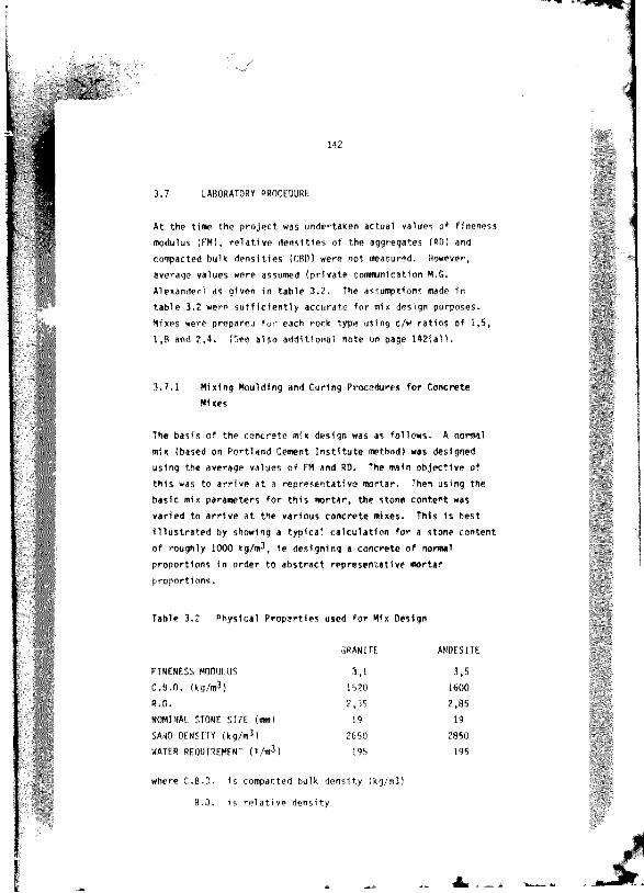
3.7 LABORATORY PROCEDURE
At the time the p ro je c t *#« undertaken actual va lue: of fineme:* modulus (FM), r e la t iv e d e n s l t le : o f the aggregate: (RD) and compacted bulk d e n s itie s (CUD) were not measured. However, average values were assumed (p riv a te communication M.G. Alexander) as given In ta b le 3 .2 . The assum ption: made In ta b le 3.2 were s u f f ic ie n t ly accu ra te fo r mix design purposes. Mixes were prepared fu r each rock type using c/w r a t io s of 1 .5 ,1 .8 and 2 ,4 . (See a lso a d d itio n a l note on page 142(a)).
3 .7 .1 Mixing Moulding and Curing Procedures fo r Concrete Ml xes
The b as is o f the concre te mix design was as fo llow s. A nor#*! mix (based on P o rtlan d Cement I n s t i tu te method) was designed using the average values o f FM and RO. The main o b jec tiv e of th is was to a r r iv e a t a re p re se n ta tiv e m ortar. Then using the bas ic mix param eters fo r th is m orta r, the stone con ten t was varied to a r r iv e a t the various co n cre te mixes. This Is bes t I l lu s t r a te d by showing a ty p ica l c a lc u la tio n fo r a stone con ten t of roughly 1000 kg/m^, 1e designing a concre te o f normal p roportions In o rder to a b s tra c t re p re se n ta tiv e m ortar p ro p o rtio n s .
Table 3.2 Physical P ro p e rtie s used fo r Mix Design
GRANITE ANDESITE
FINENESS MODULUS 3.1 3.5C.B.D. (kg/m3) 1520 1600R.D. 2,35 2.85NOMINAL STONE SIZE (ml) 19 19SAND DENSITY (kg/up) 2650 2850WATER REQUIREMENT (l/m ^) 195 195
where C.B.D. Is compacted bulk d en s ity (kg/i»3)
R.D. Is r e la t iv e d en sity
. — . A

1 4 2 ( a )
In the iv e n t a c tu . l FM values were lower (<ee Appendix A). However, th is was not c r i t i c a l , since the aim was to design re p re se n ta tiv e m ortars combined w ith th ree d if fe re n t stone c o n te n ts , namely 700 kg/m3. 1000 kg/*3 and 1300 kg/«P.This aim was s a t i s f a c to r i l y achieved In the mixes.

In the example the following symbols with refe rence to one cubic metre of - r e t i , a re used:-
^saMe Ms Mst ' s tV.c/wSa/c
Mw
mass of cement ( tg /n4l mass of sand (sg/m^l mass of stone (kg/mS) volume of stone (m-*) volume of mnrtar 1*3) cement/water r a t io sand/cement raH o mass of water (kg/*3)
volume of water
dens i ty of cement (kg/*3)
dens i ty of water (kg/m3)
dens i ty of stone and sand (kg/*3)
C/W « 1.5 volume « 1*3 mass (kg)
absolute volume (*3)
. . ' t e r (R.O. ' 1,0) 195 195T300
a 0.195
cement (R.O. « 3 ,14) 195 x 1.5 ' 293 2933T*T
a 0,093
stone (R.O. ' 2,75) 1010 x 1550 - 1037 ITZO
1037Z750
a 0 .37 /
Total abs v o l : 0,665
Therefore, sand * 1 (R.O. . 2,75)
- 0.665 - 0,335 m3
sand « 0.335 s 2750 « 921 kg
( N o t e c h a r a n a r * r a * e v a l u e n f meed a n d a t o n e R . O . f o r t h e g r a n i t e i n d a n d e a l t e a a n d a l a b e i n g n e e d ) .

Mortar r a t i o : : -
(1) R a t io ' : by ma;: (2) R a t io ' : b» volume
C/W * 1.5 c/w « 0,477
Sl/C « _3Z L . 3,15 Sa/c - 3.60292.5
's t " 1000kg/m^
'h e -e fo rr Vst ' ' C.36362750
t i a r ^ ' * 1 - 0 ,3 6 3 6 - 0,6364 #3
t i ta n " i-" 7= ' "w k . % L + _L + Sa x^_ :'_ L )(W P{ 0* c w "sa)
0 6364 « Mw (1.^ * 1 140 * i o w '
3.15 x 1.5 x _ l _ ) 2750)
C ,'.354 196 x lO '- l
Thi ret'f -e ^ ' ' 199 kg3.196x10-3
" n , o r e ^ . 1 .5 x ! 9 9 « 299 kgta 3 ,1 5 x 1 9 9 - 942 kg
' 1000 kg
2440 kg
low using th e s r q u a n t i t ie s we cam d erive th e p roportionsreq u ln jd fo r tl - g ra n ite and amdesi te co n c re te s , ad ju s tin g adxp roportions so i% ta nave equal vol umes of stone in the «dx.
a) g r a n i fw a e r « 199kg(eor.nt « 299 kgw 9 4 2 x 2 * 5 0 » 908 kg
7750
:tor,« 1000 x 2650 « 964 kg7750
b) a n d e :itew ater « 199 kgcement » 299kg:and ?A 2x2850 . 976 kg
77TJ
s to w IM O xR asO . 1036 ko7750

Each mix was daalqned according to th e above approach and thenfra c tlo n e d down to the r ifred batch s iz e . For each of thecem ent/w ater r a t io s 1e 1 ,b , 1,8 and 2 ,4 and two rock types th r^ecoarse aggregate co n ten ts were used , i . e . approxim ately 700 kg/m^, 1000 k g 'm3 and 1300 kg/m^. The various sMx p roportions a re shown In ta b le s 3 .3 and 3 .4 .
For th e dynamic t r t t h i r t y s ix 100 x 100 x 500 am long concre tebeasm were c a s t , which when cu t In h a lf provided a to ta l of seventy two 100 x 100 x 250 am long prism s fo r th e re sp e c tiv e s t a t i c t e s t s T herefo re , fo r each dynamic t e s t th e re were two specimens per cement/W ater r a t io and stone co n ten t and four fo r th e s t a t i c t e s t . Four cubes were a lso c a s t per cem ent/w ater r a t io and stone c o n ten t.
These cesm nt/w iter r a t io s and the In term ed ia te stone co n ten t were chosen such th a t the most comaonly used s t ru c tu r a l grade
concre tes would be rep re sen ted . The primary reason fo r th e range of stone co n ten ts was to see how the e l a s t ic moduli ob ta ined from them coapared with the th e o re t ic a l model p re d ic tio n s given In C hapter 4. At 700 kg/eP th e voluam co n cen tra tio n o f the stone Is q u ite low and so th e re Is l i t t l e o r no aggregate In te ra c tio n under load I . e . th e aggregate Is d isp e rsed through the m ortar m atrix . At the stone co n ten t o f 1000 kg /sP , ty p ic a l of most s t ru c tu ra l co n c re te , th e re Is a c e r ta in amount o f aggregate In te ra c tio n and a t 1300 kq/sP (approaching maximum p o ss ib le stone c o n te n t) , th e re Is a g re a te r percentage o f ag g reg s 'a
o n ta c t. F igures 3 .6 ( a ) , (b) and (c) show cro ss se c tio n !"ugh a typ ica l andes t te c . i c r e t e of cement/ a t e r r a t i o 1,8 for
.or - co i^enfs of 700, 10,:C end 1300 kg/«P r e sp e c t iv e ly , (Area
marked C, shows aggregate con tac t In each mix).
T ria l mixes of 500 kg/nP and 1400 kg/sP were c a r r ie d out and both found to be u n s a t i s f a c to ry . The 500 kg/sP mix when c a s t and cut open was found to conta in a l l I t s aggregate In the bottom

Table 3.3 Mix Proportion* fo r Granite Concrete
COARSE AGGREGATE CONTENT
kg/m)
C/W RATIO WATER
kg
CEMENT
kg
SAND
kg
STONE
kg
700 1.5 233 350 1100 700
1.8 233 420 1039 700
2.4 233 560 916 700
1000 t . s 199 299 908 964*
1.8 199 359 854 964*
2 .4 199 480 753 964*
13C0 1.5 165 248 751 1252*
1.8 165 297 709 1252*
2 .4 165 399 626 1252*
The d if fe re n c e between the p re sc rib ed and actual ito n e con ten t* a re due to average value* being used fo r th e mix design c a lc u la tio n *

1 4 7
T*b1# 3 .4 Mix P roportion* fo r And#*1t* Concrete
SE AGGREGATEINTENT(g/«M
C/W RATIO WATER
kg
CEMENT
kg
SAND
kg
STONE
kg
700 1.5 233 350 1180 751*
1.8 233 420 1117 751*
2.4 233 560 986 751*
1000 1.5 199 299 976 1036*
1.8 199 359 918 1036*
2.4 199 480 810 1036*
1300 i . s 165 248 808 1347*
1.8 165 762 1347*
2.4 1M 399 673 1347*
* Th* dfffmrence between the p resc r ibed and actual 3tom* con ten ts a re ike to average va lue ; being used fo r the *1% design c a lc u la t io n s

1 4 8
4 &
V O ID S
o
o
FIGURE 3 6 ( a ) C RO SS SECTION SHOWING AGGREGATE PARTICLES IN ANDESITE CONCRETE, c / w = 1 ,8 . TOO k g / m 3 STONE CONTENT C=IN TE R% RTICLE CONTACT

( b ) CROSS SECTION SHOWING AGGREGATE PARTICLES IN ANOESITE CONCRETE. c / w = 1 ,8 , 1000 k g / m 3 STONE CONTENT C = INTERPARTICLE CONTACT

1 5 0
FIGURE J . 6 ( c ) CROSS SECTION SHOWING AGGREGATE PARTICLES IN ANOESITE CONCRETE c / w r 1,8 1 300 k q / m 3 ' STONE CONTENTS C= INTERPARTICLE CONTACT

1 5 1
tw )f o f th# te x t b*«* w hile th e 1*00 kg/m-* mix wax ex cap tlo n a lly d i f f i c u l t to compact and th* top 301 o f th* beam rexembled a 'n o - f ln e x ' coocre t* du* to 1nxuff1:1*nt xw rtar to f i l l th# voldx b*tw**n th* aggregate .
O rdinary P o rtlan d cement, coxplying w ith SABS *71 (1971), wax uxed fo r a l l conc-x tex . The cement wax received frea h from the xuinufacturer In on# batch and each pocket wax then x to red In an a l r - t i g i t drum In th* la b o ra to ry . Thlx batch of cement w x uxed fo r *11 th e te x tx c a r r ie d out In th lx In v e x tlg a llo n . The x ta t lc and dynamic te x tln g o f each mix wax c a r r ie d out 28 dayx a f t e r c a s t in g . All cubes were a lso te s te d In u n iax ia l coagirexxlon a t 28 dayx a f t e r c a s t in g .
The main aim of the lab o ra to ry te x tln g wax to a s c e r ta in the e f f e c t o f In creasin g volume co n cen tra tio n o f aggregate on e la s t ic moduli. The h igher the stone c o n te n t, tli* g re a te r should be the measured e l a s t i c modulus. Th* M r ta r and pas ta mix r a t io s were id e n tic a l t t the re sp e c tiv e m ortars and p as te s rep o rted In C h a p t e r th e re fo re , only t h e stone co n ten t was v aried fo r th# re sp e c tiv e cem ent/w ater r a t io s . These measured moduli could then be cormared to the estim ated th e o re tic a l model p re d ic t io n s . I t Is thought th a t a t the h igher stone con ten t whore th e re Is d e f in i te I n f r o a r t l c l e c o n ta c t, the model equations xdght break down. Th1, Is because a mam assumption of the model equations I s t h a t the concre te Is a two-phase m ateria l of aggregate d isp e rsed In a mot ta r m atrix , each aggregate p a r t ic le a c tin g Independently o f I t s iieighbour.
3 .7 .2 Mixing Procedure
All the s o l id m a te r ia ls were weigh batched on a labora to ry balance to an accuracy of lOOg. The water was volume batched using a measuring cy l in d e r graduated In 20 ml In t e rv a l s .

Th# m te r la l* were Introduced In to a 100 kg pan mixer In the fo llow ing order:
1) Sand 11) Cement
111) Stone 1v) Meter
The dry m a te r ia l : were f l n t mixed by approxim ately th re e tu rn : o f th e peddle* and, w ith th e mixer a c tiv a te d , th e w ater wa: added over a period o f one m inute. Mixing wa* then con tinued fo r a fu r th e r th re e m inute*. At the end o f th l* p e rio d , the paddle* were ra1*ed and, to e n w re an w en j l i t r i b u t l o n o f the comxtltuen": m a te r ia l : , the m ixture wa* turned *evera! time* u*1ng a hand *coop. Thi* manual mixing wa: nece:*ary a* I t wa* found th a t , a f t e r mechanical mixing, th# coar*e aggregate tended to be concen tra ted more a t the c e n te r o f the mixing pan. Also In the high ito n e co n ten t mlxe*, p a r t ic u la r ly th e e n d e ; i te . the m ortar adhered to th e :1de of the pan m ixer. T herefore , to e n w re a rep re * e n ta tiv e mix, f u r th e r hand mixing wa: c a r r ie d o u t.
3 .7 .3 S lu # and V.8. Te*t*
For each mix. *tmndard ilump and V.B. t e : t * were perform ed.Three *uch t e x t : were c a r r ie d out fo r each mix. A fte r each *lump
and V.B. t ' / : t , the concre te wa* re tu rn ed to the pan m ixer and re-mixed fo r a :h o r t p e rio d . The r * : u l t i uf the :lump und V.B.
? * t: a re given in ta b le 3 .5 fo r g ra n ite and a n d e :l te mlxe*.I t can be :een th a t in general the :lu**i ind V.B. fo r each mix were re» :onably co n * 1 :ten t. implying con*1*tency In the experim ental procedure.

T a b l e 3 . 5 S l u m p a n d Y . B . T i m e s f o r G r a n i t e a n d A n d e s I t e M ix es
GRANITE ANOESITEC/W RATIO STONE SLUMP V.8. SLUMP V.B.
CONTENT(kg/Wp) (m) (m) (*)
1.5 700 SO 2.5 90 3,5*5 3.5 85 2.550 * .0 90 2.5
A ver## *8 3.3 88 2,«
1.8 700 75 2 .5 *5 2 .075 3.0 85 3,065 3 .0 95 2.5
Average 72 2 .8 88 2.5
700 70 . 50 4 .075 3 ,0 50 3 .580 3.5 65 3,5
Kvefege %-----" "3 % ~ n T ?
1.5 1000 25 6.5 20 4 ,015 5.5 10 4,525 5 5 10 3.5
Average 20 6 .0 13 4 .0
1.8 1000 IS 5.0 2b 3.510 6 .5 10 5.5
10,0 25 5,0
Average 10 7.0 20 4.7
2 / 1000 20 ?,i> fl) 7 ,015 6.5 20 6,520 8.0 20 9,0
Average 18 7.2 20 7,5

T#b1# 3 .5 S lw # mnd Y.B. Tim** fo r Grmnlt# mnd AndM lt# Nix#: (cqmtlnued)
GRANITE ANOESITEC/W RATIO STOWE SLUMP V.8. SLUMP V.8.
CONTENT(kg/"3) ("") (*) (mm) ( ; )
1.5 1300 0 5.0 0 4.00 4 .0 0 6 .00 s . o 0 5.5
A w n * 0 4.7 0 S.2
1.8 : J O 0 5.5 0 4 50 5 : 0 5 .00 5 .0 0 4.5
Av*r*g# 0 5.3 0 4.7
Z.« 1300 0 4,5 0 V0 5.5 0 10.00 6 .0 0 7.0
Avermg* 0 5.3 0 8.0

1))
3 .7 .4 C o # # c tio n
Th# 100 x 100 x 500 m b«4m would; were h a lf f i l l e d w ith concre te and tamped approxim ately 50 tim e ;, before being v ib ra ted on a mechanical v ib ra tin g ta b le fo r th e d u ra tio n ; given In ta b le 3 .5 . Thlx compaction procedure wa; a lso app lied to the101.5 ma cube aw uld;, a lthough they were hand held on the mechanical v ib ra tin g ta b le and tamped approxlam tely 25 tim e; per la y e r . The mould; were f i l e d In two la y e r ; .
Table 3 .5 V ib ra ting Time; fo r Various Stone C o n ten t:, G ran ite and A ndeelte beam Mould;
STOWE CONTENT DURATION OF VIBRATIONkg/m3 (PER HALF LAYER)
700 20 :
1000 60 :
1300 2 -2 ,5 mln
3 .7 .5 Curing
A fter compaction, th e co n cre te In th e mould: were covered w ith p la s t ic sh e e t; to prevent evaporation of w ater from th e exposed su rface . Approximately 18 hours a f t e r c a s tin g th e hardened beams and cubes were removed c a re fu lly from th e i r moulds and p laced 1n a w ater f i l l e d cu ring bath . 5y means of an 1 em ersion h ea te r and a small c ir c u la t io n pump the te a p e ra tu re In the cu Ing bath wa: held C uM lant a t 22 + 1% . All concre te specimen; fo r th is In v e s tig a tio n were s to red In a curing oath u n t i l th e time of te s t in g . Due to evaporation and the removal o f specimens from the ba th , I t was necessary to p e r io d ic a lly add w ater to the b. to keep the co n cre te , the h e a te r and the w ater pump submerged.

1 5 6
3 . 7 . 6 T e s t i n g
A h r le f o u tl in e o f th e t e s t in g procedure Is given h e re . However, a f u l l e r procedure Is o u t l ined In Appendixes C, F and E for s t a t i c , u l tra so n ic and electrodynam ic t e s t in g re sp e c tiv e ly .Before being te s te d , th e beams and cubes were removed from the cu-iiig b a th . A fte r excess w ater was wiped o f f , each specimen was weighed to an accuracy o f O .lg . The beam specimens were dimensioned p h y sic a lly in accordance w ith Appendix C i . e . the leng th measured in four p laces and s ix meesureamnts f ir both bread th and dep th , by means o f a v e rn ie r s c a le . The t e s t bees* were sc rib ed with c e n tre - lin e s and gauge len g th s to f a c i l i t a t e c e n tra l p ' . i t i o n ng f -e specimens and f ix in g o f th e s t a t i c LVDT r ig s . The sequenre of te s t in g was as fo llo w s:-
3 .7 .6 .1 U ltraso n ic T est
The u ltra so n ic t e s te r shown In f ig u re 3 .7 was c a l ib ra te d using th e standard 10 us c a l ib r a t io n b a r . The 100 x 100 x 500 m long beam specimens were p laced between th e ends of th e u ltra s o n ic tra n sd u c e rs . Care was taken to ensure th a t th e ends o f the specimens were c lean and su rface dry befo re coupling th e i r ends to the tran sd u cers w ith petroleum j e l l y . The tran sd u cers were h eld firm ly a t each end and a read ing taken . This was repeated th re e tim es fo r each specimen and an average taken fo r c a lc u la t io n purposes.
3 .7 .6 .2 Electrodynamic T est
The t e s t beams were removed from the curing tank and th e i r ends cleaned of any water and g r i t . The beam wss then clamped in to the electrodynamic apparatus and the electrodynamic e x c i t e r un i t was brought Into con tac t with the cen t re o ' the beam end. S im i la r ly , the plcx-up c . s posi t ioned on the opposite face.

Figure 3 .7 Concrete Beam in U ltraso n ic T est Apparatus T « Transducers
Figure 3.8 P aste Beam under Test In Electrodynam ic Apparatus A » V ariab le Frequency O s c il la to r E » *1ck-upB » O scilloscope F « Power Source (D.C.C « Specimen G « Dangling Layer0 » D river

F i g u r e 3 . 8 s h o w s t h e t e s t s e t u p ( f o r a p a s t e p r i s m ) . T h e
v a r i a b l e f r e q u e n c y o s r i l l a t o r w a s s w i t c h e d o n a n d t h e f r e q u e n c y
v aried u n t i l a pta '. cu tp u t t r a c e wa: observed on the o s c i l l o s c o p e . I n d i c a t i n g t h e f u n d a m e n t a l f r e q u e n c y o f t h e t e s t
s p e c i m e n s . T h e f u n d a m e n t a l f r e q u e n c y w a s s u b s e q u e n t l y r e a d o f f
t h e f r e q u e n c y c o u n t e r . T h i s p r o c e d u r e w a s - e p e e t a d t h r e e t i m e s
a n d a m e a n r e s o n a n t f r e q u e n c y r e c o r d e d . I t I s r e c o m m e n d e d t h a t
t h e o p e r a t o r e x e r c i s e s care t o e n s u r e t h e ' p e a k 1 t r a c e o b s e r v e d
o n t h e s c o p e 1 s t h a t o f t h e f u n d a m e n t a l m o d e , a n d n o t a h a r m o n i c .
3 7 . 6 . 3 S t a t i c T e s t
A f t e r t h e b e a m s w e r e t e s t e d u l t r 1 t a l l y a n d e l e c t r o -
4ynam1ca11y. they were cu t In ha sing a diam ond-tipped saw M ade. Both ends were ground p la n t to ensu-e p a ra l le l faces fo r th e s t a t i c t e s t . The s t a t i c r ig was fixed onto th e specimen as shown I n f i g u r e 3 9 a n d t h e specimen p o s i t i o n e d c e n t r a l l y I n a T ln ius Olsen coapresslon machine. Both th e LVDTs and the e l e c t r o n i c l o a d o u t p u t f r o m t h e c o m p r e s s i o n m a c h i n e w e r e
connected *0 »n X - Y r e c o r d e r . F i g u r e 3 . 1 0 shows the overa ll experim ental s e t u p . The load ou tpu t was read d ir e c t ly from t h e
T ln ius 0 1 s e n machine. T h e p r e - l o a d g i v e n I n A p p e n d i x C w a s
app lied and th e LVDTs z e r o e d b y means o f a m ultim eter c o n n e c t e d
a c r o s s t h e X - Y r e c o r d e r . T h e l o a d was t h e n Increased a t 1 5
MPa/min up to one th ird o f th e mean com pressive s tre n g th . The load was (teld a t th i s value fo r one minute and then decreased a t th e a fo re - mentioned loading r a te to the value o f *he p re -lo a d . The X-Y reco rder pens fo r lo n g itu d in a l and tra n sv e rse deform ation were re-zeroed and th e opera tio n repeated fo r two successive p lo ts . The s t a t i c e l a s t ic swdulus was determ ined from the th i rd p lo t .
F in a lly , the pens were re-zeroed and a t the above loading ra te the specimen was loaded to f a i lu r e , x.ie X-Y reco rder c a l ib ra t io n s were se t so as to give adequate s e n s i t iv i ty fo r each p lo t .

Figure 3 .9 Concrete Specimen held In S ta t ic RigA - LYOT to measure lo n g itu d in a l s t r a in B « LVDT to measure la te r a l s t r a in
F igure 3.10 S ta t ic T est Equipment A » Specimen hel^ In r ig B « T lnlus Olsen Compression machine C « XT P lo t te r 0 » M ultim eter E " O.C. Power source

3 . 7 . 6 . 4 C u b e S t r e n g t h
A fter w eighing, the cubes were te s te d on an Amsler type 103 co#pre::4on t e s t in g machine (cap ac ity 2000 kN). The cube: were c e i t ie d In the machine and loaded to f a i lu r e a t a load ing ra te of 15 #a/m1m. The f a i lu r e load wa* recorded to the n e a re s t 1 kN. The r e s u l ts o ' the cube t e s t s are given In apoendlx C.
3 .8 RESULTS
The r e s u l t s o f the s t a t i c , electrodynam ic and u ltra so n ic e la s t ic modulus t e s t s a re given In Appendix C. E and F re sp e c tiv e ly .The f in a l column of the ta b le s In d ic a te s the mode of f a i lu r e of the various specimens on being loaded to f a i lu r e .
3 .9 DISCUSSION OF RESULTS
T able 3.7 shews E ' load ( i . e . th e load corresponding to one th ird the expected f a i lu r e s tre n g th of the con cre te ) and the expected f a i lu r e s t r e s s fo r each o f th e cem ent/w ater r a t io s . Theexpected f a i lu r e s t r e s s e s a re based on cube s tren g th and notprism s tre n g th . The ac tu a l measured cube and prism f a i lu r e s tre n g th s a re tab u la ted In ta b le 3 .8 (a ) and (b) fo r both g ra n ite and a n d es ite concre te re sp e c tiv e ly . The r e s u l t s show th a t the prism compressive s tre n g th s a re c o n s is te n tly lower than the expected f a i lu r e s t r e s s and v ice versa fo r cube s tre n g th s , e sp e c ia l ly th e an d es ite mixes. The s tre n g th s fo r g ra n ite are lower than th e i r an d esite c o u n te rp a m . At the low cem ent/w»terr a t io s and stona con ten ts o f 1000 kg/m^ and 1300 kg/*3. thepercentage d if fe re n c e o f the g ra n ite prisms i s -97.2% and -70,7% re sp e c tiv e ly , compared w ith only -30 ,8? and -3 7 ,M d if fe re n c e in the re sp e c tiv e a n d es lte mixes. Thi: may be due to the b e tte r bond p ro p e rtie s of the an d es ite aggregate g iv ing r i s e to higher s tre n g th s than th e i r g ra n ite c o u n te rp a r t: . However, o v era ll the

1 6 1
p r l ;* rm fre s s iv * stren q th * a re am average of 43% low er than expected f a i , . , r e a t r n g th a fo r the g ra n ite e ix ea (n eg lec tin g t i e re a u lta fo r ceeen t/w a te r r a t io 1,5 and atone co n ten t 1000 and1300 kg/nth and -34% lower fo r an d ea itea . These re su l t - - would help to provide an exp lanation for the prism r e s u l t s recorded in ch ap te r Z fo r paatea and m ortar*. The priam compreaaive s t reng ths measured were a lso considerably lower than expected
f a i lu re a tre a a e a . C oncrete la c le a r ly no t aa s e n s i t iv e to aspect r a t io aa p a s te s ; however the prism compreaaive stren g th * are c o n s i s te n t ly low.
Engineering t e x t* 3 \ ̂ d iscuss comparison* m ainly between cube and c y lin d e r a tre n c th . In th i s p ro je c t p r ism were employed. However, severa l fa c to rs a f fe c t in g c y lin d e r s tre n g th a lso apply to th e case o f p rism s. For e x a m l* . th e re s tr a in in g e f f e c t of th e te s t in g machine p la te n s extend over the e n t i r e h e ig h t o f a cube, but leav es p a r t o f the prism u n affe c ted . This would tend to give h ig h er cube s tre n g th s than prism s tre n g th s . Although the r a t io of cube s tr e n g th /c y lin d e r s tre n g th decreases as s tren g th o f concre te in c re a se s , i t i s o ften assumed th a t cube s tre n g th Is 1.Z5 times th a t of a c y lin d e r . I t i s a lso known th a t a* the specimen s i t e In c re a se s , so s tre n g th and v a r ia b i l i ty of s tren g th d e c re a s e ^ .
The aspect r a t io ( r a t i o of h e ig h t to l e a s t l a t a 'a l dimension h /d) a lso plays an la g o r ta n t ro le . For values of h /d sm aller than 1,5 measured s tre n g th Increases rap id ly owing to the aforementioned p la ten r e s tr a in in g a f f e c t . Between a h /d r a t io of 1,5 and 4 ,0 s tren g th Is l i t t l e a f fe c te d , w hile fo r an h/d r a t io g re a te r than 5 s tren g th f a l l s o ff markedly and slenderness a f fe c ts become apparen t. The concre te prisms te s te d in th is p -b je c t had an aspect r a t io o f 2 ,5 .
At the lower cement/watcr r a t i o s combined with the h igher stone con ten ts , p a r t i c u l a r l y n the g r a n i t e s , the re i s a p o s s i b i l i t y th a t we may be measuring a d i f f e r e n t m ater ia l behaviour with
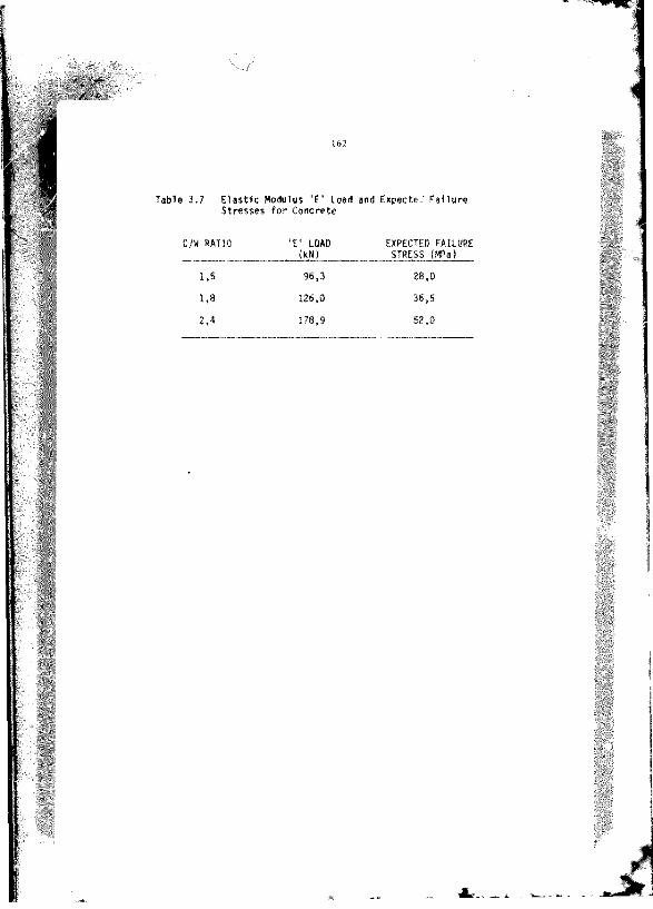
T#b1# 3 .7 E la s t ic Modwlu: E ' Load and Expecte. Fallw r* S tro a aa : fo r Concrete
C/W RATIO 'E ' LOAD EXPECTED FAILURE(UN) STRESS (MPa)

Table 3.8(a) Mean Cube and PM*# Strength: for GraniteConcrete:
C/W MEAN CUBE CWRESSIVE MEAN PRISM COMPRESSIVERATIO STRENGTH (MPa) STRENGTH (MPa) ,
STONE CONTENT kg/#3 STONE CONTENT kg/#3700 1000 1300 700 1000 1300
1.5 28.5 30.1 31,4 20.S 14.2 16.4% d iffe ren ee from expected
+1.8 +7.0 +10,8 -36.6 -97.2 -70.7
1.8 37.9 4 3 .S 42,9 25.8 26.2 24,8% di ffe ren ce fro # expected
+3.7 +15.1 +14,9 -41.5 -39.3 -47.2
2.4 .8 .9 82.8 65.6 38.1 34.8 34.8% d iffe re n c e fro # expected
+11.7 +17.2 +20.7 36.5 -49.4 -49 .4
Table 3 .8 (b ) Mean Cube and Prim : S tre n g th : fo r A ndeaite C oncrete:
C/W MEAN CUBE COMPRESSIVE MEAN PRISM COMPRESSIVERATIO STRENGTH (MPa) STRENGTH (MPa)
STONE CONTENT kg/m- STONE CONTENT kq/aH700 1000 1300 700 1000 1300
1,5 33.5 35.1t d if fe re n c e +16,4 +20,2fro# expected
1.8 43.7 46,01 di fference +16,5 +20.7fro# expected2.4 63.7 54,6
% d iffe ren ce +18.4 +19.5fro# expected
38,3 23.5 21.4 20.3+26.9 -19.1 -30.8 -37.9
48.8 29.1 29.5 26.6+25.2 -25.4 -23.7 -37.2
38.8 35.1 35.1-34.0 -48.1 -48.1
t DIFFERENCE - MEASURED - PREDICTEDMEASURED % 100
NOTE Both the cube and prism s treng th values are an average of four t e s t specimens

modwlwi Nnd PoiMon'% r a t io fo r g ra n ite and an d e s lte concrete r e sp e c tiv e ly . The r e i u l t : in f e r th a t the modulus 1 ; not adverse ly a ffe c te d by the low r1«» i t r e n g th : . I f a d if f e r e n t m ateria l behaviour were being measured, we would expect th a t low s tren g th would a lso r e s u l t In a low modulus. However, th is I s c le a r ly not the case . T herefore, the modulus r e s u l ts are accep tab le .
3 .9 .1 S ta t ic E la s t ic Modulus
The r e s u l ts of the s t a t i c modulus t e s t s are given In appendix C. The average s t a t i c e l a s t i c moduli a re tab u la te d In ta b le 3 .9 (a ) and (b) fo r g r a r l te and an d es lte concre te re sp e c tiv e ly . The r e s u l t s show c o n s is te n t moduli values fo r each mix.
F igure 3 .1 1 (a ) and (b) show th e p lo ts of cube s tre n g th ag a in s t s t a t i c e l a s t i c moduli fo r g ra n ite and a n d es lte concre te r e sp e c tiv e ly . The p lo ts c l e f l y show th a t the s t l f f e r aggregate has a h igher modulus and coa^ ss lv e s tre n g th , in* lin e s f i t t e d to th e r e s u l t s are l in e a r w - on l in e s . I t I s very In te re s t in g th a t both the l in e s fo r g ra n ite and an d e s lte are p a r a l l e l . They only d i f f e r a t Y " In te rc e p t o rd in a te on the s t a t i c modulus o f e l a s t i c i t y axis th e Co va^ue a : defined Insec tio n 3 .5 ) . From the graphs. C,, f c g ra n ite s I s 18.8 6Pa andfo r an d es lte C@ Is 27,1 UPa). From the y 'aohs we can derive two equations r e la t in g the Z8-day cube s tren g th f ;^ and the 28-day s t a t i c modulus of e l a s t i c i t y Egg fo r g ra n lte and a n d es lte co n c re te . The re la t io n sh ip I l lu s t r a te d In f ig u re 3 .11 (a) fo r g ra n ite concrete may be expressed In terms of the equation:
E, (GPa) - 0.210 f ^ * 18,84 .......... (3 .9)
and for andes l te as I l l u s t r a t e d In f igu re 3 .11(b):
E, (GPa) . 0.213 % + 27.13 .......... (3.10)

1 6 5
Tabl* 3 .9 (a )
STONECONTENT
kg/w3
Average S ta t i c Modulus f o r G ran ttf Concrete
C/W RATIO
and P o ls so n ':
AVERAGESTATICMOOUIUS
B a
R atio Values
AVERAGESTATICPOISSON'SMHO
'X ) 1.5 23,46 0.171.8 29.93 0.182.4 29.78 0.18
1000 1.5 24,24 3.161 P 27.70 0.1*
31,37 0.20
1300 i . s 2 4 .M 0.161.8 29.30 0.172.4 33.24 0.20
Table 3 .9 (b ) Average S ta t ic Modului fo r A nd*:it* Concrete
'n d Fo1;:om'* R atio Value*
STONE C/W RATIO AVERAGE AVERAGECONTENT
kg/*3
STATICX'uULUS
y .
STATICPOISSON'SRATIO
700 1.5 ; .8 i 0,201.8 %93 0,202.4 15,21 0,21
1000 1.5 34,50 0,201.8 37,34 0.212.4 40,60 0.22
1300 1.5 39,66 0.20

1 6 6
5 0
3 0
20
E , . 0 , 2 1 f u , + 18 6 4 ( G P a )
2 0 M 3 0 M 4 0 4 S 1 0 W * 0 M 7 0 7 *
CUBE C N U lM fN O 8 T M W » rM (M P N I
n # ] 1 1 o C U K IT N E N O TM V 5 . :T * T T C M OOULU: t W W N i r E C O N C R E T E )

Author Grills Frank
Name of thesis Static And Dynamic Elastic Modulus Testing Of Concrete And Its Constituents And Comparison Of Results
With Theoretical Models. 1986
PUBLISHER: University of the Witwatersrand, Johannesburg
©2013
LEGAL NOTICES:
Copyright Notice: All materials on the Un i ve r s i t y o f the Wi twa te r s rand , Johannesbu rg L ib ra ry website are protected by South African copyright law and may not be distributed, transmitted, displayed, or otherwise published in any format, without the prior written permission of the copyright owner.
Disclaimer and Terms of Use: Provided that you maintain all copyright and other notices contained therein, you may download material (one machine readable copy and one print copy per page) for your personal and/or educational non-commercial use only.
The University of the Witwatersrand, Johannesburg, is not responsible for any errors or omissions and excludes any and all liability for any errors in or omissions from the information on the Library website.