chapter 2 temporary sediment control management 2…
TRANSCRIPT

Best Management Practices Manual
01/14 Chapter 2 Temporary Sediment Control Management
CHAPTER 2 TEMPORARY SEDIMENT CONTROL MANAGEMENT
2.1 Introduction The requirement that sediment control be initiated on all exposed soil surfaces within a given timeframe is an integral compliance component on virtually all construction and maintenance projects. Temporary sediment control best management practices (BMPs) are short-term measures that should be considered during a period where areas are disturbed due to construction or maintenance.
A temporary sediment control BMP is normally used for 1—6 months, or until a more permanent BMP is put into place. Temporary sediment control BMPs are typically used in conjunction with erosion control BMPs and are designed and installed to keep as much sediment on-site as possible.
The proper use of temporary sediment control BMPs allows for cleaner water runoff into receiving waters such as streams, rivers, and lakes. Erosion control is the primary and initial consideration in a construction project that disturbs soil, and sediment control or collection should be the secondary consideration. If erosion control is implemented correctly, there should be little or no sediment control or collection needed.
2.2 Temporary Sediment Control Management Goals Temporary sediment control goals consist of:
1. Perimeter Controls a. Ensure that no sediment, or only a minimal amount, enters or leaves the
project area.
b. Treat or filter sediment-laden discharge waters, before leaving the project area, as many times as needed to meet receiving water standards.
2. Controls within the Project a. Maintain erosion and sediment control on cut-and-fill slopes and in the ditches
or channels.
b. Divert stormwater away from the project, especially disturbed areas.
c. Protect all potential receiving bodies of water (ponds, streams, wetlands, etc.).
3. Final Product a. Coordinate all temporary sediment controls to facilitate permanent measures.

01/14 Chapter 2 Temporary Sediment Control Management
Temporary sediment control management involves the use of the following BMPs: Typical Highway Construction Activities
Temporary Sediment Control Management
Best Management Practices Dem
olis
h Pa
vem
ent/S
truct
ures
Cle
ar a
nd G
rub
Con
stru
ct A
cces
s Roa
d
Gra
ding
(inc
. cut
and
fill
slop
es)
Cha
nnel
Exc
avat
ion
Cha
nnel
Pav
ing
Tren
chin
g/U
nder
grou
nd D
rain
age
Und
ergr
ound
Dra
inag
e Fa
cilit
y In
stal
latio
n
Dra
inag
e In
let M
odifi
catio
n
Util
ity T
renc
hing
Util
ity In
stal
latio
n
Subg
rade
Pre
para
tion
Bas
e Pa
ving
AC
Pav
ing
Con
cret
e Pa
ving
Saw
Cut
ting
Join
t Sea
ling
Grin
d/G
roov
e
Stru
ctur
e Ex
cava
tion
Erec
t Fal
sew
ork
Brid
ge/S
truct
ure
Cons
truct
ion
Rem
ove
Fals
ewor
k
Strip
ing
Mis
cella
neou
s Con
cret
e W
ork
Soun
d W
alls
/Ret
aini
ng W
alls
Plan
ting
and
Irrig
atio
n
Con
tract
or A
ctiv
ities
Trea
tmen
t BM
P C
onst
ruct
ion
SC-1 Dikes and Berms X X X X X X X X X X
SC-2 Check Dam X X X X X X
SC-3 Gravel Bag Berm X X X X X X X X X X
SC-4 Street Sweeping and Vacuuming X X X X X X X X X X X X X X X X X X X X X
SC-5 Sandbag Barrier X X X X X X X X X X X X
SC-6 Inlet/Outlet Protection X X X X X X X X X X X X X X X X X
SC-7 Silt Fence X X X X X X X X X X X X
SC-8 Fiber Rolls X X X X X X X X X X
SC-9 Sediment/Desilting Basin X X X X X X X X
SC-10 Sediment Trap X X X X X X X X X X X X
SC-11 Temporary Construction Entrances X X X X X
SC-12 Temporary Roads X X X
SC-13 Entrance/Outlet Tire Wash X X X X X

Best Management Practices Manual SC-1 Dikes and Berms
01/14 Chapter 2 Temporary Sediment Control Management
SC-1 DIKES AND BERMS Refer to: ITD Standards and Specifications for Highway Construction, Section 212 ITD Standard Drawings P-1-E
Definition and Purpose A temporary dike or berm is a ridge constructed of compacted soil, composted material, gravel, crushed rock, sandbags, gravel bag barriers, or straw bales that intercepts and prevents runoff from entering a disturbed area, and diverts or directs the water to a controlled or stabilized drainage outlet. Dikes or berms can be located or placed immediately along cut or fill slopes, along the perimeter of a disturbed area, or adjacent to streams to prevent water from a construction site from entering a body of water.
Dikes or berms can also be used to direct water to slope drains, ditches, channels, sediment basins, or sediment traps.
Appropriate Applications
• Prevent runoff from entering or overflowing onto newly-constructed slopes, or intercept or divert runoff coming off the slope.
• Intercept runoff from upland undisturbed areas, and divert or direct runoff to a sediment basin or specified location.
• Intercept runoff and sediment from exposed disturbed areas, such as a newly-constructed road or slope, and filter sediment or redirect water to a slope drain, sediment basin, or other specified location.
• Install a perimeter around a disturbed area to protect adjacent undisturbed areas and prevent off-site runoff from entering the area.
• Still the water in larger sediment basins, allowing more sediment to settle.
BMP Objectives
Perimeter Control
Slope Protection
Borrow and Stockpiles
Drainage Areas
Sediment Trapping
Stream Protection
Temporary Stabilizing
Permanent Stabilizing

Best Management Practices Manual SC-1 Dikes and Berms
01/14 Chapter 2 Temporary Sediment Control Management
• Prevent high water from streams, ponds, or lakes from entering a project.
• Prevent runoff from entering into bodies of water.
• Divert runoff from a roadway under construction with a waterbar to a roadside ditch.
Limitations
• Do not use dikes and berms in streams or channels.
• Space, degree of slope, and access can be limiting or prohibitive factors for installing a dike or berm.
• The dike or berm must be designed and constructed to avoid causing erosion or washout due to diverting the water and creating concentrated flow runoff.
• Dikes or berms should be used for small drainage areas and must be properly keyed and compacted to avoid washout.
• Sandbags or gravel bag barriers can be used to construct dikes or berms in more restricted or hard-to-access areas. See SC-3 and SC-5.
• Straw bale sediment barriers are to be used in emergencies only and require constant maintenance and repair. Straw bales, properly installed and anchored, can be placed uphill of a silt fence to act as a sediment barrier prior to water passing through a silt fence.
Design Parameters
• If soil is used for dikes or berms, the soil should consist of clayey material.
• Compaction of the dike or berm material (if soil or rock) is required per the project specifications.
• The height of dikes or berms comprised of soil or rock should be sufficient to prevent water from overtopping the structure.
• Compost dikes or berms may be left as a permanent filter or part of the natural landscape and may include a permanent seed mix.
• Geosynthetic liners should be placed on the uphill or upstream side and properly anchored to prevent erosion or washout of the dike or berm.
• If used as an interceptor/diversion structure, the berm should be built on the contour with a consistent and gradual gradient to a stabilized outlet.
• Dikes and berms shall be graded in order to divert runoff to a stabilized outlet or other area using a gradient as flat as possible to prevent erosion.
• Straw bales shall be installed in a trench and anchored properly. The straw bales shall be laid on the sides opposite the bale twine, and any holes or gaps shall be plugged tightly with wedged straw. A geosynthetic liner, properly anchored, shall be used to increase the effectiveness of the straw bale dike or berm.
• Field adjustments shall be made as necessary to ensure proper performance.

Best Management Practices Manual SC-1 Dikes and Berms
01/14 Chapter 2 Temporary Sediment Control Management
Maintenance and Inspection
• Conduct inspections as required by the NPDES permit or contract specifications.
• Remove sediment retained by the berm once it has reached one-half of the exposed height of the berm, and dispose of properly to an approved site. Remove channel or ditch obstructions and dispose in an approved location.
• If temporary, remove the dikes or berms only after other permanent BMPs are in place and the site is stabilized. Sometimes the dike or berm may be left in place and continue operating after final acceptance of the project, or the maintenance section for that area may be required to remove the dikes or berms at a later date.
• If straw bales are used during emergencies, check for failure, damaged bales, undercutting or end runs. Replace or repair as necessary.
• Straw bales shall be removed from the site after permanent BMPs are in place and the site is stabilized.

Best Management Practices Manual SC-2 Check Dam
01/14 Chapter 2 Temporary Sediment Control Management
SC-2 CHECK DAM Refer to: ITD Standards and Specifications for Highway Construction, Section 212. ITD Standard Drawing P-1-D & P-2-B. QPL Category: 212 Sediment Retention Fiber Rolls
Definition and Purpose
Check dams are constructed of rock, sediment retention fiber rolls, gravel bags, sandbags, or other proprietary product placed across a natural or manmade channel or drainage ditch. A properly designed, constructed, and maintained check dam will reduce scour and channel erosion by reducing flow velocity and encouraging sedimentation.
Check dams in conjunction with sediment basins are usually able to capture a large percentage of the sediments suspended in the water.
Appropriate Applications A check dam either filters the water for sediment as it passes through the dam or retains the water, allowing the sediment to settle while the water flows over the dam. Check dams may be installed:
• In small open channels.
• During the establishment of grass linings in drainage ditches or channels.
• In temporary ditches where the short length of service does not warrant establishment of erosion-resistant linings.
The following products are available to construct an effective temporary check dam:
• Rock Check Dams are constructed primarily of riprap and are more effective in ditches where the velocity of runoff is expected to be high, or in situations where the surface area exceeds 5 acres and drainage is funneled into a ditch or channel. An erosion control geotextile should be used at the bottom or base of the rock check dam to prevent undercutting. In some instances, erosion control geotextile should also be installed on the overflow portion of the dam to prevent erosion.
BMP Objectives
Perimeter Control
Slope Protection
Borrow and Stockpiles
Drainage Areas
Sediment Trapping
Stream Protection
Temporary Stabilizing
Permanent Stabilizing

Best Management Practices Manual SC-2 Check Dam
01/14 Chapter 2 Temporary Sediment Control Management
• Sediment Retention Fiber Roll Check Dams are made from natural or organic material (e.g. straw, coconut fiber (coir), wood fiber (excelsior) mulch, or compost) wrapped in biodegradable netting. Sediment retention fiber roll can be cut to length and used for ditch or channel protection and are easily installed. A series of stair steps made of fiber rolls is effective in filtering and collecting water. Most fiber rolls are degradable and can be left in place after construction. See SC-8, Sediment Retention Fiber Rolls.
• Sandbag Check Dams are best suited for emergencies such as floods or slides when other materials may be difficult to acquire. Individual sand bags can be filled and placed to form a check dam where water needs to be diverted or channeled. Tightly abut the bags and stack them using a pyramid approach. Place the bags in an interlocking pattern to assure proper sealing and stability; the upper rows of sandbags shall overlap the joints in lower rows. Bags shall not be stacked higher than 3 feet.
• Straw Bale Check Dams should only be used in emergencies and are better suited as a temporary berm or dike to capture or direct runoff where structural strength is not required.
• Temporary check dams should be removed after the purpose is served or when permanent BMPs are in place and final stabilization is achieved, unless directed otherwise.
•
Limitations
• Check dams:
Shall be used on slopes with a gradient of 3:1 or less.
Shall not be used in live streams, except as allowed with proper approval and permitting.
Shall not be placed in channels that are already grass-lined unless erosion is expected, as installation may damage vegetation.
Shall not be constructed from silt fence.
Require extensive maintenance following high velocity flows.
Promote sediment trapping, which can be re-suspended during subsequent storms or removal of the check dam if not properly maintained.
Shall be constructed of straw bales only in emergencies.
Design Parameters
• The size of the area to be drained, the gradient or slope of the ditch and anticipated high velocity runoff must all be considered when choosing the appropriate type of check dam.
• Rock check dams are usually the most effective to use, but the correct rock size and combination must be available and installed properly. Rock size should vary from 1 inch to 8 inches, with 8 inches making up 30 percent or more of the mix.

Best Management Practices Manual SC-2 Check Dam
01/14 Chapter 2 Temporary Sediment Control Management
• Check dams shall be placed at a distance and height to allow small pools to form behind them. The check dams shall be installed approximately 6 feet from the outfall device and at regular intervals based on slope gradient and soil type.
• For installation of multiple check dams, backwater from downstream check dam shall reach the toe of the upstream dam. On steep slopes, typically greater than 3H:1V, the spacing will become so close that consideration should be given to using a slope drain (rock lined or pipe) instead of a check dam (see EC-5, Slope Drains).
• The center of the check dam should be 6 to 10 inches lower than the top of the outside edge to form a weir for the overflow. The top of the outside edges should be at least 6 inches lower than the roadway, banks, or back slope to prevent water from flowing onto the roadway or undercutting the banks.
• High flows shall safely flow over the check dam without an increase in upstream flooding or damage to the check dam.
• Undercutting shall always be considered, regardless of the type of check dam being used. For rock check dams, a geotextile shall be placed under the bottom of the dam. For sediment retention fiber rolls, a trench (3 to 5 inches deep) shall be dug to key in the roll. Excavated soil shall be placed on the upstream side of the wattle and compact. The fiber rolls shall be anchored with wood stakes according to manufacturer’s recommendations.
• Where grass is used to line ditches, check dams may be removed when grass has matured sufficiently to protect the ditch or swale.
• Rock shall be placed individually by hand or by mechanical means, but should not be dumped to achieve complete ditch or swale coverage.
• Stable inlets and outlets shall be designed and constructed prior to installation of check dams.
• If straw bales are used, the bales shall be placed in a trench backfilled on the upstream side and compacted. Rock 1 to 3 inches shall be placed in the overflow area both upstream and downstream (similar to a rock check dam) to provide additional stability and strength. An overflow shall be formed in the center of straw bale check dams.
• Careful inspection is important during installation of check dams and channel liners. Refer to special contract provisions or plans to ensure that check dams and liners are installed and perform properly during their lifetime.
• Field adjustments shall be made as necessary to ensure proper performance.
Qualified Products List Criteria See SC-8 (Fiber Rolls).
Maintenance and Inspection
• Conduct inspections as required by the NPDES permit or contract specifications.
• Make any repairs necessary to keep the check dams in good working order and check for signs of undercutting.

Best Management Practices Manual SC-2 Check Dam
01/14 Chapter 2 Temporary Sediment Control Management
• Remove accumulated debris and sediments from behind the check dams when sediment reaches a depth of one-half the original height of the dam and prior to permanent seeding or soil stabilization. Dispose of all materials properly at an approved site.
• For sediment retention fiber rolls, clean out accumulated sediment or replace the roll as necessary.
• Replace rock as necessary to maintain the correct height of rock check dams.
• Replace sandbag dam fabric as necessary.
• Remove check dam when no longer needed or when directed by the Engineer.

Best Management Practices Manual SC-3 Gravel Bag Barrier
01/14 Chapter 2 Temporary Sediment Control Management
SC-3 GRAVEL BAG BARRIER Refer to: ITD Standards and Specifications for Highway Construction, Section 212.
Definition and Purpose A gravel bag barrier consists of a single row of gravel bags that are installed end-to-end to form a barrier across a slope to intercept runoff, reduce its flow velocity, release the runoff as sheet flow, and provide some sediment removal. Gravel bag barriers can also be used where flows are moderately concentrated, such as ditches, swales, and storm drain inlets to divert and/or detain flows.
Appropriate Applications
• Along the perimeter of a site.
• Along streams and channels.
• Below the toe of exposed and erodible slopes.
• Down slope of exposed soil areas.
• Around stockpiles.
• Where flows are moderately concentrated, such as ditches, swales, and storm drain inlets.
• Across channels if constructing check dams or diversions.
• Parallel to a roadway to keep sediment off paved areas.
• At the top of slopes to divert runoff away from disturbed slopes.
• To divert or direct flow or create a temporary sediment basin.
• During construction activities in channels when the contributing drainage area is less than 5 acres.
• When extended construction period limits the use of either silt fences or straw bale barriers.
• When site conditions or construction sequencing require adjustments or relocation of the barrier to meet changing field conditions and needs during construction.
BMP Objectives
Perimeter Control
Slope Protection
Borrow and Stockpiles
Drainage Areas
Sediment Trapping
Stream Protection
Temporary Stabilizing
Permanent Stabilizing

Best Management Practices Manual SC-3 Gravel Bag Barrier
01/14 Chapter 2 Temporary Sediment Control Management
• At grade breaks of exposed and erodible slopes to shorten slope length and spread runoff as sheet flow.
Limitations
• Degraded gravel bags may rupture when removed, spilling contents.
• Installation can be labor-intensive.
• Burlap bags have limited durability for long-term projects.
• When used to detain concentrated flows, maintenance requirements increase.
Construction
• When using as a linear control for sediment removal:
Install along a level contour.
Turn ends of gravel bag row upslope to prevent flow around the ends.
Generally, use gravel bag barriers in conjunction with temporary soil stabilization controls up slope to provide effective control.
• When using for concentrated flows:
Stack gravel bags to required height using a pyramid approach.
Upper rows of gravel bags shall overlap joints in lower rows.
• Construct gravel bag barriers with a setback of at least 3 feet from the toe of a slope. Where it is not practical due to specific site conditions, the gravel bag barrier may be constructed at the toe of the slope, but shall be constructed as far from the toe of the slope as practical to allow for maintenance access.
Design Considerations
• Bag Material: Bags shall be woven polypropylene, polyethylene, or polyamide fabric, minimum unit weight 4 ounces per square yard; mullen burst strength exceeding 300 psi in conformance with the requirements in ASTM designation D3786; and ultraviolet stability exceeding 70 percent in conformance with the requirements in ASTM designation D4355.
• Fill Material: Gravel shall be between 0.4 and 0.8 inch in diameter and shall be clean and free from clay balls, organic matter, and other deleterious materials. The filled bags shall be between 28 and 48 pounds in mass. Fill material is subject to approval by the Engineer.
Maintenance and Inspection
• Conduct inspections as required by the NPDES permit or contract specifications.
• Reshape or replace gravel bags as needed.
• Repair washouts or other damages as needed.
• Removed sediment shall be incorporated in the project at locations designated by the Engineer or disposed of in an approved manner.

Best Management Practices Manual SC-3 Gravel Bag Barrier
01/14 Chapter 2 Temporary Sediment Control Management
• Remove gravel bag berms when no longer needed. Remove sediment accumulation, and clean, re-grade, and stabilize the area.
Best Management Practices Manual SC-4 Street Sweeping and Vacuuming
01/14 Chapter 2 Temporary Sediment Control Management
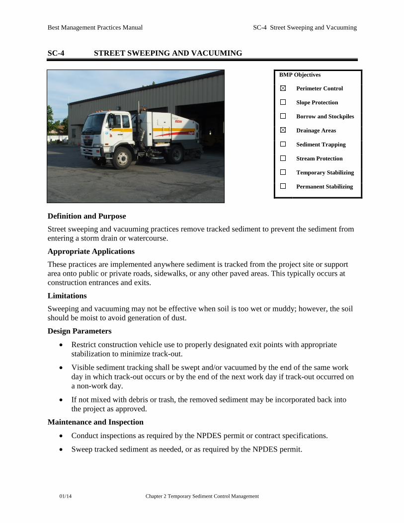
SC-4 STREET SWEEPING AND VACUUMING
Definition and Purpose Street sweeping and vacuuming practices remove tracked sediment to prevent the sediment from entering a storm drain or watercourse.
Appropriate Applications These practices are implemented anywhere sediment is tracked from the project site or support area onto public or private roads, sidewalks, or any other paved areas. This typically occurs at construction entrances and exits.
Limitations Sweeping and vacuuming may not be effective when soil is too wet or muddy; however, the soil should be moist to avoid generation of dust.
Design Parameters
• Restrict construction vehicle use to properly designated exit points with appropriate stabilization to minimize track-out.
• Visible sediment tracking shall be swept and/or vacuumed by the end of the same work day in which track-out occurs or by the end of the next work day if track-out occurred on a non-work day.
• If not mixed with debris or trash, the removed sediment may be incorporated back into the project as approved.
Maintenance and Inspection
• Conduct inspections as required by the NPDES permit or contract specifications.
• Sweep tracked sediment as needed, or as required by the NPDES permit.
BMP Objectives
Perimeter Control
Slope Protection
Borrow and Stockpiles
Drainage Areas
Sediment Trapping
Stream Protection
Temporary Stabilizing
Permanent Stabilizing

Best Management Practices Manual SC-4 Street Sweeping and Vacuuming
01/14 Chapter 2 Temporary Sediment Control Management
• Be careful not to sweep up any unknown substance or any object that may be potentially hazardous.
• Adjust brooms frequently to maintain proper contact with the ground and maximize efficiency of sweeping operations.
• After sweeping is finished, properly dispose of sweeper wastes at an approved dumpsite.

Best Management Practices Manual SC-5 Sandbag Barrier
01/14 Chapter 2 Temporary Sediment Control Management
SC-5 SANDBAG BARRIER Refer to: ITD Standards and Specifications for Highway Construction, Section 212.
Definition and Purpose
A sandbag barrier is a temporary linear sediment barrier consisting of stacked sandbags, designed to intercept and slow the flow of sediment-laden sheet flow runoff. Sandbag barriers allow sediments to settle from runoff before water leaves the construction site. Large sandbag barriers can also be used for in-water work and/or water diversions if site conditions allow and appropriate permits are obtained.
Appropriate Applications
• To divert or direct flow or create a temporary sediment/desilting basin.
• During construction activities in stream beds when the contributing drainage area is less than 5 acres.
• To capture and detain non-stormwater flows until proper cleaning operations occur.
• When site conditions or construction sequencing require adjustments or relocation of the barrier to meet changing field conditions and needs during construction.
• To temporarily close or continue broken, damaged, or incomplete curbs. Appropriate locations:
• Along the perimeter of a site.
• Along streams and channels.
• Below the toe of exposed and erodible slopes.
• Down slope of exposed soil areas.
BMP Objectives
Perimeter Control
Slope Protection
Borrow and Stockpiles
Drainage Areas
Sediment Trapping
Stream Protection
Temporary Stabilizing
Permanent Stabilizing

Best Management Practices Manual SC-5 Sandbag Barrier
01/14 Chapter 2 Temporary Sediment Control Management
• Around stockpiles.
• Across or along channels to serve as a barrier for utility trenches or provide a temporary channel crossing for construction equipment, or to create an in-stream diversion for a work space to reduce stream impacts.
• Parallel to a roadway to keep sediment off paved areas.
• At the top of slopes to divert roadway runoff away from disturbed slopes.
• Along the perimeter of vehicle and equipment fueling and maintenance areas or chemical storage areas.
Limitations
• The drainage area upstream of the barrier shall be limited to 5 acres.
• Degraded sandbags may rupture when removed, spilling sand.
• Installation can be labor-intensive.
• Limited durability of bag material.
• When used to detain concentrated flows, maintenance may increase.
Design Considerations
• Bag Material: Bags shall be woven polypropylene, polyethylene, or polyamide fabric, minimum unit weight 4 ounces per square yard; mullen burst strength exceeding 300 psi in conformance with the requirements in ASTM designation D3786; and ultraviolet stability exceeding 70 percent in conformance with the requirements in ASTM designation D4355.
• Fill Material: Sand shall be clean and free from clay balls, organic matter, and other deleterious materials that could leach from the bag. Fill material is subject to approval by the Engineer.
Construction Guidelines
• When used as a linear sediment control:
Install along a level contour.
Turn ends of sandbag row upslope to prevent flow around the ends.
Generally, use sandbag barriers in conjunction with temporary soil stabilization controls upslope to provide effective erosion and sediment control.
• Construct sandbag barriers with a set-back of at least 3 feet from the toe of a slope. Where it is determined to be not practical due to specific site conditions, the sandbag barrier may be constructed at the toe of the slope but shall be constructed as far from the toe of the slope as practicable.
• When used for in water work:
Ensure appropriate permits are obtained for in water work and fill material in waters of the U.S.

Best Management Practices Manual SC-5 Sandbag Barrier
01/14 Chapter 2 Temporary Sediment Control Management
Use clean sand to fill bags.
Place bags in a manner that causes the least amount of disturbance to the stream bed.
Maintenance and Inspection
• Conduct inspections as required by the NPDES permit or contract specifications.
• Reshape or replace sandbags as needed, or as directed by the Engineer.
• Repair washouts or other damages as needed, or as directed by the Engineer.
• Removed sediment shall be incorporated in the project at locations designated by the Engineer or disposed of as approved.
• Remove sandbags when no longer needed. Remove sediment accumulation, and clean, re-grade, and stabilize the area.

Best Management Practices Manual SC-6 Inlet/Outlet Protection
01/14 Chapter 2 Temporary Sediment Control Management
SC-6 INLET/OUTLET PROTECTION Refer to: ITD Standard Specifications, Sections 212, 640, and 718. ITD Standard Drawings P-1-A and P-1-H. QPL Category: 212 Inlet Protection
Definition and Purpose Temporary inlet and outlet treatment of runoff water ensures that the water leaving the construction site has a reduced sediment load.
• Inlet treatment: The focus is to capture sediment, that has been suspended in stormwater as a result of ground disturbance, from entering a conveyance system (man-made or natural stream). In this case the disturbed area is the source of the sediment at the point of concentrated flow.
• Outlet treatment: The focus is to not cause erosion at the point of concentrated discharge of relatively clean stormwater from a disturbed area. In this case the disturbed area is not the source of the sediment but it is the source of the concentrated flow.
Appropriate Applications Inlet Protection
• Inlet protection is recommended on any structure that conveys water away from a construction site to a sediment basin or receiving water.
• Storm drain inlet treatment is used where:
A permanent storm drain structure is being constructed on-site and there is danger of sediment silting or filling in the structure prior to site stabilization and placement of permanent BMPs, or where ponding around the inlet structure could interfere with traffic within the site.
Sediment-laden runoff may enter an inlet.
BMP Objectives
Perimeter Control
Slope Protection
Borrow and Stockpiles
Drainage Areas
Sediment Trapping
Stream Protection
Temporary Stabilizing
Permanent Stabilizing
Best Management Practices Manual SC-6 Inlet/Outlet Protection
01/14 Chapter 2 Temporary Sediment Control Management
• Sediment filtering of the runoff used in combination with sediment basins, or other erosion and sediment control BMPs can be effective in reducing the sediment load.
• Recommended inlet controls consist of:
Fiber wattles, placed upstream to or around the inlet (see Standard Drawing P-1-H)
Riprap or graded aggregate and erosion control geotextile
Sediment basin upstream of the inlet
Cinder block and graded aggregate (see Standard Drawing P-1-H)
Sandbags or gravel bag barriers
Framework with silt fence and wire mesh (see Standard Drawing P-1-H)
Approved pre manufactured inlet filter devices
Outlet Protection Outlet protection should be comprised of riprap and riprap/erosion control geotextile that is installed at the outlets of all conveyance systems, sediment trap basins, ditches or channels where the velocity of flow may cause erosion in the receiving area.
Limitations
• Inlet treatment measures require constant monitoring and maintenance. Where approaches to inlets are paved, special consideration and practices such as sandbags may be needed to reduce water velocity.
Straw bales are not an acceptable application for inlet treatment, except for emergencies.
Silt fencing is not an acceptable application for inlet treatment without framework and wire mesh backing.
Gravel bag barriers for inlet protection are applicable when sheet flows or concentrated flows exceed 0.5 cubic feet per second, and it is necessary to allow for overtopping to prevent flooding.
Fiber rolls and foam barriers are not appropriate for locations where they cannot be properly anchored to the surface.
Inlet protection requires an adequate area for water to pond without encroaching upon traveled way and should not present itself to be an obstacle to oncoming traffic.
Inlet protection may require other methods of temporary protection to prevent sediment-laden stormwater and non-stormwater discharges from entering the storm drain system.
Sediment removal may be difficult in high-flow conditions or if runoff is heavily sediment-laden. If high-flow conditions are expected, other onsite sediment trapping techniques (e.g., check dams) should be used in conjunction with inlet protection.

Best Management Practices Manual SC-6 Inlet/Outlet Protection
01/14 Chapter 2 Temporary Sediment Control Management
For drainage areas larger than 1 acre, runoff shall be routed to a sediment trapping device designed for larger flows. See SC-9 (Sediment/Desilting Basin) and SC-10 (Sediment Trap).
Traffic obstruction and durability must be considered when choosing inlet protection in areas with expected traffic.
• Outlet treatment measures require the right size and thickness of riprap to be effective, depending on flow volume and velocity, soil conditions, and slope angle.
Design Considerations
• Inlet: The area immediately surrounding the inlet should be as flat as possible.
Sediment retention fiber rolls can be effective to filter low-velocity-flow runoff, which in most instances provides a continuous filtering barrier around the inlet. For higher velocity flows, masonry block can be installed between the roll and the inlet to provide added strength and stability. The masonry block shall be laid on its flat side so water can pass through the openings in the block.
If graded aggregate is used in lieu of a sediment retention fiber roll, ½” wire mesh shall be installed between the masonry block and the aggregate. The graded aggregate should be washed gravel 0.75 inches in diameter, with less than 5 percent being 4.75 mm (No. 4 sieve) in diameter or smaller..
• Outlet: The outlet should be located to discharge onto a stabilized area or into a channel to prevent erosion.
Unless otherwise specified, all riprap used in an outlet shall be 6 inches or larger.
An erosion control geotextile should be installed prior to the placement of the riprap, with the riprap placed directly on top of the geotextile.
A basin on the discharge side of the outlet may be needed to dissipate water velocity and prevent erosion.
Construction Guidelines
• Inlet: Leave inlet treatment in place and operational until the drainage area is completely stabilized with a more permanent BMP. The measure may be left in place past final acceptance of the project. Make field adjustments as necessary to assure proper performance.
Level the area immediately surrounding the inlet as much as possible.
Install a dike or berm on the downstream side of the inlet to avoid bypassing the inlet after the installation of the filtering device.
Anchor and stabilize the filtering device properly to avoid washout or undercutting.
Construct a sediment basin upstream–the width, size, and depth to be determined by the availability of room.
Best Management Practices Manual SC-6 Inlet/Outlet Protection
01/14 Chapter 2 Temporary Sediment Control Management
Install wire mesh with a 0.4- to 0.6-inch opening over the inlet (grate) to prevent rock from entering the inlet. Extend the wire mesh over the edges of the inlet (grate) by a minimum of 12 inches.
Install an approved pre manufactured inlet filter devices per the manufacturer’s recommendations.
• Outlet: Make field adjustments as necessary to assure proper performance.
Construct outlets concurrently with pipe, culvert, dikes, berms, and inlets before allowing water flows to pass over or through the outlet.
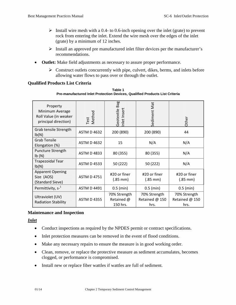
Qualified Products List Criteria Table 1
Pre-manufactured Inlet Protection Devices, Qualified Products List Criteria
Property Minimum Average
Roll Value (in weaker principal direction) Te
st
Met
hod
Geot
extil
e Ba
g In
let I
nser
t
Sedi
men
t Mat
Oth
er
Grab tensile Strength lb(N) ASTM D 4632 200 (890) 200 (890) 44
Grab Tensile Elongation (%) ASTM D 4632 15 N/A N/A
Puncture Strength lb (N) ASTM D 4833 80 (355) 80 (355) N/A
Trapezoidal Tear lb(N) ASTM D 4533 50 (222) 50 (222) N/A
Apparent Opening Size (AOS) (Standard Sieve)
ASTM D 4751 #20 or finer (.85 mm)
#20 or finer (.85 mm)
#20 or finer (.85 mm)
Permittivity, s-1 ASTM D 4491 0.5 (min) 0.5 (min) 0.5 (min)
Ultraviolet (UV) Radiation Stability ASTM D 4355
70% Strength Retained @
150 hrs.
70% Strength Retained @ 150
hrs.
70% Strength Retained @ 150
hrs.
Maintenance and Inspection Inlet
• Conduct inspections as required by the NPDES permit or contract specifications.
• Inlet protection measures can be removed in the event of flood conditions.
• Make any necessary repairs to ensure the measure is in good working order.
• Clean, remove, or replace the protective measure as sediment accumulates, becomes clogged, or performance is compromised.
• Install new or replace fiber wattles if wattles are full of sediment.

Best Management Practices Manual SC-6 Inlet/Outlet Protection
01/14 Chapter 2 Temporary Sediment Control Management
• Where evidence of sediment accumulation adjacent to the inlet exists, remove the deposits by the same work day in which it is found or by the end of the following work day if removal the same day is not feasible.
• Remove accumulated sediment in the sediment trap basin when filled to half the depth of the basin.
• Dispose of the sediment properly.
• Remove any rock, leaves, debris or trash that has been deposited on the grate and wire mesh to prevent further clogging of the entrance to the inlet.
Outlet
• Conduct inspections as required by the NPDES permit or contract specifications.
• Make any necessary repairs to ensure the measure is in good working order.
• Remove accumulated sediment from the sediment trap basin.
• Dispose of the sediment as approved.

Best Management Practices Manual SC-7 Silt Fence
01/14 Chapter 2 Temporary Sediment Control Management
SC-7 SILT FENCE Refer to: ITD Standard Specifications, Sections 212 and 718 ITD Standard Drawing P-1-B QPL Category: 212 Silt Fence
Definition and Purpose Silt fences consists of permeable geotextile material stretched and attached to supporting posts that assists in sediment containment by capturing/intercepting most of the eroded soil particles (sediment) and slowing the runoff velocity to allow particle settling. Welded wire backing may be necessary for added strength.
Appropriate Applications
• Downslope perimeter of a disturbed area, including stockpiles.
• Below the toe of exposed and erodible slopes, allowing water to pass through.
• At natural drainage areas.
• At grade breaks on cut or fill slopes and above interceptor dikes, berms, channels, or ditches.
Limitations
• Shall not be used at the top of a slope.
• Shall not be used in a live stream, ditch, channel, or drainage way or where soil conditions prevent proper installation.
• Are not effective unless trenched and keyed in.
• Are not intended for use as mid-slope protection on slopes steeper than 4H:1V.
BMP Objectives
Perimeter Control
Slope Protection
Borrow and Stockpiles
Drainage Areas
Sediment Trapping
Stream Protection
Temporary Stabilizing
Permanent Stabilizing

Best Management Practices Manual SC-7 Silt Fence
01/14 Chapter 2 Temporary Sediment Control Management
• Must be maintained regularly to ensure effectiveness.
• Must be removed and disposed of upon project completion.
• Shall not be used below slopes subject to creep, slumping, or landslides.
• Shall not be used to divert flow.
• For slopes steeper than 2H :1V and that contain a high number of rocks or large dirt clods that tend to dislodge, it may be necessary to install additional protection immediately adjacent to the bottom of the slope, prior to installing silt fence. Additional protection may be a chain link fence or a cable fence.
• For slopes adjacent to water bodies or environmentally sensitive areas, additional temporary soil stabilization BMPs shall be used.
Material Considerations
• Wood stakes shall be commercial quality lumber of the size and shape shown on the plans. Each stake shall be free from decay, splits or cracks longer than the thickness of the stake, or other defects that would weaken the stakes.
• Fabric shall meet the specifications found in section 718 of the spec book.
• Staples used to fasten the fence fabric to the stakes shall be not less than 1.75 inches long and shall be fabricated from 0.06-inch or heavier wire. The wire used to fasten the tops of the stakes together when joining two sections of fence shall be 0.12-inch or heavier wire. Galvanizing of the fastening wire is not required.
Installation Considerations In most instances, silt fences should be used on the toe of a slope or disturbed areas where surface water will run off the construction site. Install silt fence perpendicular to the flow of water, along the contours of the slope. Install perimeter protection before clearing and grubbing, excavating haul roads, benches, or any soil-disturbing construction activity.
• Follow all manufacturers’ recommendations for proper installation.
• Generally, silt fences shall be used in conjunction with soil stabilization controls up slope to provide effective sediment control.
• Trenches shall not be excavated wider and deeper than necessary for proper installation of the temporary linear sediment barriers.
• Excavation of the trenches shall be performed immediately before installation of the temporary linear sediment barriers.
• Silt fences should be constructed with a set-back of at least 3 feet from the toe of a slope. If this is not practical due to specific site conditions, the silt fence may be constructed at the toe of the slope.
• Geotextile shall not be attached to trees.
Best Management Practices Manual SC-7 Silt Fence
01/14 Chapter 2 Temporary Sediment Control Management
• When welded wire is used, the wire shall be fastened to the upslope side of the posts using heavy-duty wire staples, tie wires, or hog rings. The wire support shall be extended to the bottom of the trench.
• Designated vegetated buffer areas shall not be disturbed.
• Field adjustments shall be made as necessary to ensure proper performance.
• The fences should remain in place until the disturbed area is permanently revegetated and/or stabilized with non-vegetative controls.
Maintenance and Inspection
• Conduct inspections as required by the NPDES permit or contract specifications.
• Repair undercut silt fences.
• Repair or replace split, torn, slumping, or weathered fabric. Holes, depressions, or other ground disturbance activities caused by the removal of the temporary silt fences shall be backfilled and repaired in conformance with the Standard Specifications.
• Silt fences that are damaged and become unsuitable for the intended purpose, as determined by the Engineer, shall be removed, disposed of outside the highway right-of-way in conformance with the Standard Specifications, and replaced.
• If concentrated surface flow occurs after installation place rock berms or other controls in the areas of concentrated flow to direct and spread the flow.
• When the silt fence is removed, cut the geotextile at ground level, remove the wire and post, fill and compact post holes and anchorage trench, spread the sediment, prepare for seeding, and grade fence alignment to blend with adjacent ground.

Best Management Practices Manual SC-8 Sediment Retention Fiber Rolls
01/14 Chapter 2 Temporary Sediment Control Management
SC-8 SEDIMENT RETENTION FIBER ROLLS Refer to: ITD Standard Specifications, Section 212 and 711 ITD Standard Drawing P-1-B QPL Category: 212 Sediment Retention Fiber Rolls
Definition and Purpose A sediment retention fiber roll consists of wood excelsior, rice or wheat straw, compost, or coconut fibers that are rolled or bound into a tight tubular roll and placed on the toe and face of slopes to intercept runoff, reduce its flow velocity, release the runoff as sheet flow and provide removal of sediment from the runoff. Sediment retention fiber rolls may also be used for inlet protection and as check dams or shoreline protection under certain situations. Sediment retention fiber rolls include degradable fiber wattles, degradable logs, and compost socks.
Appropriate Applications
• Sediment retention fiber rolls may be used as check dams in unlined ditches if low flow exists and if approved by the Engineer [refer to SC-2 (Check Dams)].
• Sediment retention fiber rolls may be used for drain inlet protection if properly anchored and if approved by the Engineer [refer to SC-6 (Inlet/Outlet Protection)].
• Degradable logs may be used for shoreline protection if approved by the Engineer.
• Sediment retention fiber rolls may be located:
Along the toe, top, face, and at grade breaks of exposed and erodible slopes to shorten slope length and spread runoff as sheet flow.
Below the toe of exposed and erodible slopes.
Down-slope of exposed soil areas.
Around temporary stockpiles.
BMP Objectives
Perimeter Control
Slope Protection
Borrow and Stockpiles
Drainage Areas
Sediment Trapping
Stream Protection
Temporary Stabilizing
Permanent Stabilizing
Best Management Practices Manual SC-8 Sediment Retention Fiber Rolls
01/14 Chapter 2 Temporary Sediment Control Management
Along the perimeter of a project.
Limitations
• Erosion may occur if sediment retention fiber roll is not adequately trenched in.
• Sediment retention fiber rolls may be used for drainage inlet protection if they can be properly anchored.
• Sediment retention fiber rolls are difficult to move once saturated.
• Sediment retention fiber rolls can be removed by unexpected high flows if not properly staked and trenched in.
• Sediment retention fiber rolls have a limited sediment capture zone.
• Sediment retention fiber rolls must be maintained (cleaned out) once 50% of capacity is reached.
• Sediment retention fiber rolls shall not be used on slopes subject to creep, slumping, or landslide.
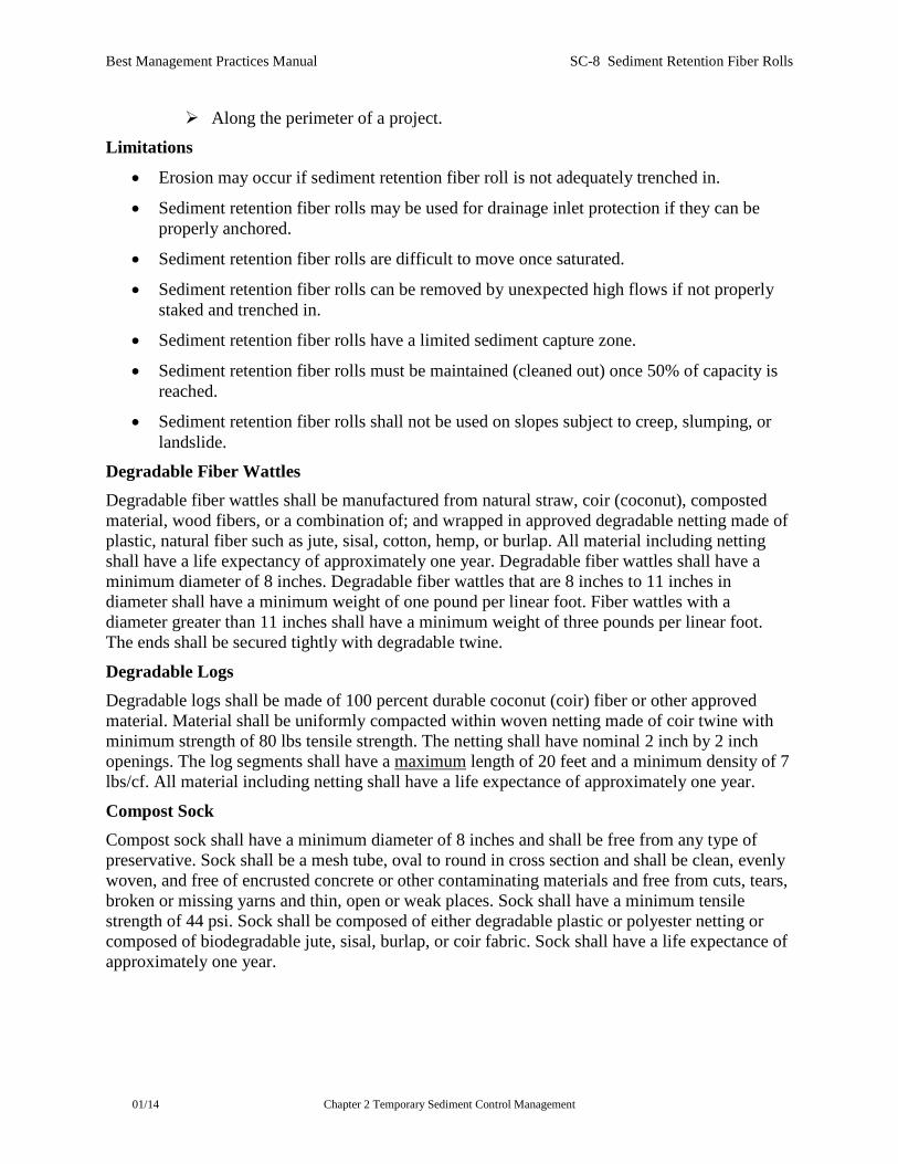
Degradable Fiber Wattles Degradable fiber wattles shall be manufactured from natural straw, coir (coconut), composted material, wood fibers, or a combination of; and wrapped in approved degradable netting made of plastic, natural fiber such as jute, sisal, cotton, hemp, or burlap. All material including netting shall have a life expectancy of approximately one year. Degradable fiber wattles shall have a minimum diameter of 8 inches. Degradable fiber wattles that are 8 inches to 11 inches in diameter shall have a minimum weight of one pound per linear foot. Fiber wattles with a diameter greater than 11 inches shall have a minimum weight of three pounds per linear foot. The ends shall be secured tightly with degradable twine.
Degradable Logs Degradable logs shall be made of 100 percent durable coconut (coir) fiber or other approved material. Material shall be uniformly compacted within woven netting made of coir twine with minimum strength of 80 lbs tensile strength. The netting shall have nominal 2 inch by 2 inch openings. The log segments shall have a maximum length of 20 feet and a minimum density of 7 lbs/cf. All material including netting shall have a life expectance of approximately one year.
Compost Sock Compost sock shall have a minimum diameter of 8 inches and shall be free from any type of preservative. Sock shall be a mesh tube, oval to round in cross section and shall be clean, evenly woven, and free of encrusted concrete or other contaminating materials and free from cuts, tears, broken or missing yarns and thin, open or weak places. Sock shall have a minimum tensile strength of 44 psi. Sock shall be composed of either degradable plastic or polyester netting or composed of biodegradable jute, sisal, burlap, or coir fabric. Sock shall have a life expectance of approximately one year.

Best Management Practices Manual SC-8 Sediment Retention Fiber Rolls
01/14 Chapter 2 Temporary Sediment Control Management
Removal
• Degradable fiber rolls are typically left in place.
• If sediment retention fiber rolls are removed, sediment accumulation shall be collected and disposed of, and holes, trenches, depressions, or any other ground disturbance shall be filled and compacted to blend with adjacent ground as approved by the Engineer.
Maintenance and Inspection
• Conduct inspections as required by the NPDES permit or contract specifications.
• Repair or replace split, torn, unraveling, or slumping sediment retention fiber rolls.
Best Management Practices Manual SC-9 Sediment Basin
01/14 Chapter 2 Temporary Sediment Control Management pg. 1
SC-9 SEDIMENT BASIN Refer to: ITD Standard Specifications, Section 212.
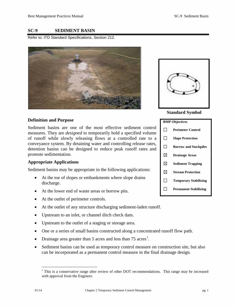
Standard Symbol Definition and Purpose Sediment basins are one of the most effective sediment control measures. They are designed to temporarily hold a specified volume of runoff while slowly releasing flows at a controlled rate to a conveyance system. By detaining water and controlling release rates, detention basins can be designed to reduce peak runoff rates and promote sedimentation.
Appropriate Applications Sediment basins may be appropriate in the following applications:
• At the toe of slopes or embankments where slope drains discharge.
• At the lower end of waste areas or borrow pits.
• At the outlet of perimeter controls.
• At the outlet of any structure discharging sediment-laden runoff.
• Upstream to an inlet, or channel ditch check dam.
• Upstream to the outlet of a staging or storage area.
• One or a series of small basins constructed along a concentrated runoff flow path.
• Drainage area greater than 5 acres and less than 75 acres1.
• Sediment basins can be used as temporary control measure on construction site, but also can be incorporated as a permanent control measure in the final drainage design.
1 This is a conservative range after review of other DOT recommendations. This range may be increased with approval from the Engineer.
BMP Objectives
Perimeter Control
Slope Protection
Borrow and Stockpiles
Drainage Areas
Sediment Trapping
Stream Protection
Temporary Stabilizing
Permanent Stabilizing

Best Management Practices Manual SC-9 Sediment Basin
01/14 Chapter 2 Temporary Sediment Control Management pg. 2
Limitations
• Normally collects particles that are sand-sized or larger, with fine clay-sized particles remaining in suspension. Because finer silts or clays may not settle out, additional sediment control measures may be required (e.g., chemical treatment).
• Require large surface areas to permit infiltration and sedimentation.
• Cannot be used in active stream channel or established natural buffer area. (Reference 1)
• May present a drowning hazard. Protective fencing and warning signs are required on permanent basins and should be considered on temporary basins if there is the potential for unauthorized persons at the basin site.
Required Design Parameters
• All basins shall be designed by a Professional Engineer (P.E.) registered in the State of Idaho.
• The basin must be designed to meet all applicable local ordinance(s).
• For projects with Construction General Permit (CGP) coverage, the minimum required detention volume is either (1) the calculated volume of runoff from a 2-year, 24-hour storm, or (2) 3,600 cubic feet per acre drained. Maintain at least half of the designed detention capacity at all times. (Reference 1)
• Water within the detention storage volume shall be withdrawn from the surface of the basin through a skimmer or similar device, unless infeasible. If infeasible, documentation shall be provided in the SWPPP as to why it is infeasible. (Reference 1)
• Some traps may be regulated as “dams” by the Idaho Department of Water Resources (IDWR). Coordination with IDWR is required prior to construction of a “dam”. See Table 1 to determine if a proposed design would be regulated. (Reference 2)
• A sediment basin may be considered a “Shallow Injection Well” and be subject to additional regulation by IDWR if the dug or drilled depth is greater than the largest surface dimension, it is an improved sink hole, or it has a subsurface fluid distribution system. (Reference 3)

Best Management Practices Manual SC-9 Sediment Basin
01/14 Chapter 2 Temporary Sediment Control Management pg. 3
Table 1. (Provided by IDWR)
MATRIX SERVES ALL HYDRAULIC
BARRIERS *
H E I G H T O F
B A R R I E R
Less than 6.0 Feet
6 -to- 10 Feet
10 Feet or More
S T O R A G E
Less than 10.0 Acre-Feet
NO NO NO
10 -to- 50 Acre-Feet
NO NO YES
50 Acre-Feet or More
NO YES YES
* Note: In general accordance w/ Idaho Code 42.1709, any Significant or High Hazard structure
may be regulated on a case-by-case basis regardless of height or storage capacity

Best Management Practices Manual SC-9 Sediment Basin
01/14 Chapter 2 Temporary Sediment Control Management pg. 4
Additional Design Parameters2
• Design of the sediment basin should be based upon the total area being drained. Consideration should be given to the volume of sediment, the percent of sediment load to be removed, particle size, ground water levels (min. 3ft. separation), and estimated peak rates of runoff.
• When possible, place the basin in a natural swale, using natural slopes so that only the frontal dike needs to be constructed. The top toe of the natural or excavated slope that starts the basin shall be no higher than the top of the basin dike portion. Construct the basin so that excavated and embankment quantities will be reasonably balanced.
• The size (volume) of the basin should be based on an assessment of potential downstream impacts and expected sedimentation rates. Only providing the required detention volume to capture the design storm will not ensure maximum constituent removal. An effectively configured basin will have a long flow path, establish low velocities, and avoid stagnant areas.
• The basin may be designed to include baffles (berms) or other deflectors, such as floating sediment barriers, to spread and reduce the velocity of water flow throughout the basin. Runoff should enter the basins as far from the outlet as possible to maximize retention time.
• The dike must be compacted to at least 95% of maximum standard dry density. Maximum permeability is 𝐾 = 2.5 × 10⁻⁷.
• The entrance to the basin must be stabilized with rip rap of appropriate depth and length for inlet velocity and slope. Riprap should extend to the bottom of the basin.
• The minimum sediment storage volume should be 900 cubic feet per acre. (Reference 4)
• Detention storage depth should be 3-5 feet to promote sedimentation.
• The length to width ratio should be at least 3:1 and preferably 5:1. (Reference 5)
• Side slopes should be gentle (3:1 or flatter). Steep slopes create a greater potential for erosion and sloughing inside the basin, an increased safety hazard and make routine maintenance (i.e. mowing) more difficult.
• Minimum top width of the embankment should be 6ft. (Reference 6)
• The basin should not produce a public nuisance (vegetation overgrowth, vector issues associated with standing water, etc.) To reduce the potential for these issues and allow for adequate sedimentation, the drawdown time should be 48-72 hrs.
• The skimmer should be sized to discharge at a pre-determined flow rate. Maximum outflow rate from the skimmer shall not be more than the pre-development rate of runoff.
2 These parameters are considered Best Engineering Practices (BEPs). Unless noted by a specific, referenced source, these parameters were either published in the previous version of this document and are still considered BEPs or they were developed as BEPs in this version after reviewing similar guidance in other states.

Best Management Practices Manual SC-9 Sediment Basin
01/14 Chapter 2 Temporary Sediment Control Management pg. 5
• The sediment clean out elevation should be clearly marked on the discharge riser. Sediment shall be removed when it reaches the level marked on the riser. The clean out elevation should correspond to the top of the sediment storage capacity or a level that will maintain at least half of the detention storage capacity of the basin at all times.
• An emergency spillway (lined flume or riprap trough with geotextile liner) should be included in the basin, in case the skimmer is plugged or blocked. The emergency spillway structure will be designed on a site-specific basis to safely pass flows above the design capacity of the basin. The area to which the spillway discharges must be stabilized using rip rap and/or other energy dissipation devices.
Discharge Riser
• The discharge riser will consist of a vertical pipe or box-type riser joined to a horizontal conduit (barrel) that will extend through the embankment. The horizontal pipe conduit (barrel) should be a minimum of 12 inches in diameter. The riser should be a minimum of 15 inches in diameter. The cross-sectional area of the riser should be at least 1.5 times the cross-sectional area of the horizontal conduit.
• Crest Elevation: The crest elevation of the riser should be at least 12 inches below the elevation of the control section of the emergency spillway.
• Base: The riser should have a base attached with a watertight connection and should have sufficient weight to prevent flotation of the riser.
• Antivortex Device: Install an antivortex device on the top of the riser. An approved antivortex device is a thin, vertical plate normal to the centerline of the dam and firmly attached to the top of the riser. The plate dimensions are: length = diameter of the horizontal pipe.
• Trash Rack: A trash rack should be welded across the top of the riser.
• Antiseep Collars: Conduits through embankments should be provided with antiseep collars. All basins should have a minimum of one antiseep collar located near middle of fill that is rectangular, blocking all potential flow through the backfilled material and extending to the sides of the barrel trench. The horizontal dimension should be at least 24 inches larger than the barrel diameter. The bottom side of the antiseep collar should extend a minimum of 24 inches below the grade line, and the topside should extend 12 inches above the barrel.
• See Figures 1-3 for design examples.
Installation
• Locate and construct temporary sediment basin early in the construction phase.
• Clear existing vegetation and other debris if present in the basin construction area.
• Construct the sediment basin in an area where there is sufficient room and topography to allow for access and clean-out of the basin or incorporate an access road into the design.
• The banks or slope of the sediment basin may require that geosynthetic liner or jute matting be installed to protect against erosion. Care must be taken not to disturb the liners

Best Management Practices Manual SC-9 Sediment Basin
01/14 Chapter 2 Temporary Sediment Control Management pg. 6
or matting during clean out of the basin. A temporary soil stabilization or erosion control surface application may be used to stabilize the surrounding area.
Maintenance and Inspection
• Conduct inspections as required by the NPDES permit or contract specifications.
• Make necessary repairs to ensure the basin is operational and performing properly. • Clean out the basin when the designed sediment storage capacity is reached. Dispose of
the removed sediment in an approved areas that will prevent the sediment from returning to the basin or downstream areas during a storm event.
• Maintain at least half of the designed detention capacity at all times. (Reference 1) • If not incorporated into the final stormwater design as a permanent BMP, remove the
basin infrastructure and re-grade the area to match preconstruction conditions.

Best Management Practices Manual SC-9 Sediment Basin
01/14 Chapter 2 Temporary Sediment Control Management pg. 7
Figure 1. Example of basin layout (skimmer and anti-seep collars not shown)
Adapted from Natural Resources Conservation Services, Conservation Practice Standard, Sediment Basin, Code 350, January 2010, pg 350-2.
Sediment Storage
Detention
Auxiliary Spillway
Principal Spillway
1.0' min.
Storage
900 cu. ft./acre
3600 cu. ft./acre
Flood StorageBased on aux. spwy.
flow reqmt.
Required Sediment Basin Storage Capacities

Best Management Practices Manual SC-9 Sediment Basin
01/14 Chapter 2 Temporary Sediment Control Management pg. 8
Figure 2: Skimmer detail example
Adapted from the Pennsylvania Department of Environmental Protection, Erosion and Sediment Pollution Control
Program Manual, March 2012, pg. 167.

Best Management Practices Manual SC-9 Sediment Basin
01/14 Chapter 2 Temporary Sediment Control Management pg. 9
Figure 3. Photo showing example of a riser, trash rack, anti-vortex device, skimmer and landing pad.
Adapted from Pennsylvania Department of Environmental Protection, Erosion and Sediment Pollution Control Program Manual, March 2012, pg. 166.

Best Management Practices Manual SC-9 Sediment Basin
01/14 Chapter 2 Temporary Sediment Control Management pg. 10
References:
1) U.S. Environmental Protection Agency, Construction General Permit 2012, Section 2.1.3.2. 2) Idaho Statues, Title 42 Irrigation and Drainage – Water Rights and Reclamation, Chapter 17 Department of Water Resources – Water Resource Board, Section 42-1711. 3) Idaho Department of Water Resources, Idaho Department of Water Resources Memo for Shallow Injection Well Criteria, Effective date 1 July 2011. Available at http://itd.idaho.gov/enviro/Stormwater/FAQs/default.htm. 4) Natural Resources Conservation Services, Conservation Practice Standard, Sediment Basin, Code 350, January 2010. 5) Idaho Department of Environmental Quality, IDEQ Storm Water Best Management Practices Catalog, September 2005, pg. 77. 6) Natural Resources Conservation Services, Conservation Practice Standard, Pond, Code 378, May 2011.
Best Management Practices Manual SC-10 Sediment Trap
01/14 Chapter 2 Temporary Sediment Control Management
SC-10 SEDIMENT TRAP Refer to: ITD Standard Specifications, Section 212. ITD Standard Drawings P-1-C and P-1-D.
Standard Symbol
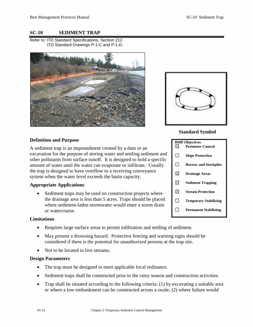
Definition and Purpose A sediment trap is an impoundment created by a dam or an excavation for the purpose of storing water and settling sediment and other pollutants from surface runoff. It is designed to hold a specific amount of water until the water can evaporate or infiltrate. Usually the trap is designed to have overflow to a receiving conveyance system when the water level exceeds the basin capacity.
Appropriate Applications
• Sediment traps may be used on construction projects where the drainage area is less than 5 acres. Traps should be placed where sediment-laden stormwater would enter a storm drain or watercourse.
Limitations
• Requires large surface areas to permit infiltration and settling of sediment.
• May present a drowning hazard. Protective fencing and warning signs should be considered if there is the potential for unauthorized persons at the trap site.
• Not to be located in live streams.
Design Parameters
• The trap must be designed to meet applicable local ordinance.
• Sediment traps shall be constructed prior to the rainy season and construction activities.
• Trap shall be situated according to the following criteria: (1) by excavating a suitable area or where a low embankment can be constructed across a swale, (2) where failure would
BMP Objectives Perimeter Control
Slope Protection
Borrow and Stockpiles
Drainage Areas
Sediment Trapping
Stream Protection
Temporary Stabilizing
Permanent Stabilizing

Best Management Practices Manual SC-10 Sediment Trap
01/14 Chapter 2 Temporary Sediment Control Management
not cause loss of life or property damage, (3) to provide access for maintenance, including sediment removal and sediment stockpiling in a protected area, and (4) where infiltration will not negatively impact groundwater.
• On projects with Construction General Permit (CGP) coverage, traps shall be sized to retain, at a minimum, the 2 yr, 24 hour storm or 3,600 cubic feet per acre of contributing drainage area. Multiple traps and/or additional volume may be required to accommodate site-specific rainfall and soil conditions. (Reference 1)
• The volume of impounded water shall infiltrate within 72 hours so as not to produce a public nuisance by causing a vector issues associated with standing water, unless specified differently in local ordinance.
• The length to width ratio should be at least 2:1.
• Side slopes should be gentle (3:1 or flatter). Steep slopes create a greater potential for erosion and sloughing inside the basin and an increased safety hazard.
• Minimum top width of the embankment should be 6ft. (Reference 2)
• Some traps may be regulated as “dams” by the Idaho Department of Water Resources (IDWR). Coordination with IDWR is required prior to construction of a “dam”. See Table 1 to determine if a proposed design would be regulated. (Reference 3)
• A sediment basin may be considered a “Shallow Injection Well” and be subject to additional regulation if the dug or drilled depth is greater than the largest surface dimension, it is an improved sink hole, or it has a subsurface fluid distribution system. (Reference 4)
• The design shall include maintenance requirements, including sediment removal, to ensure continuous function of the trap.
• Rock or vegetation shall be used to protect the trap overflow against erosion. The entire trap may be lined with rock or geotextile, if necessary.

Best Management Practices Manual SC-10 Sediment Trap
01/14 Chapter 2 Temporary Sediment Control Management
Table 1. (Provided by IDWR)
MATRIX SERVES ALL HYDRAULIC
BARRIERS *
H E I G H T O F
B A R R I E R
Less than 6.0 Feet
6 -to- 10 Feet
10 Feet or More
S T O R A G E
Less than 10.0 Acre-Feet
NO NO NO
10 -to- 50 Acre-Feet
NO NO YES
50 Acre-Feet or More
NO YES YES
* Note: In general accordance w/ Idaho Code 42.1709, any Significant or High Hazard structure
may be regulated on a case-by-case basis regardless of height or storage capacity
Maintenance and Inspection
• Conduct inspections as required by the NPDES permit or contract specifications.
• If captured stormwater has not completely infiltrated within 72 hours, then dewater the sediment trap using an approved method.
• Repair damage and remove obstructions as needed or as directed by the Engineer.

Best Management Practices Manual SC-10 Sediment Trap
01/14 Chapter 2 Temporary Sediment Control Management
• Remove accumulated sediment when the volume of sediment has reached one-half the designed trap volume. (Reference 1)
• Properly dispose of sediment and debris removed from the trap.

Best Management Practices Manual SC-10 Sediment Trap
01/14 Chapter 2 Temporary Sediment Control Management
References:
1) U.S. Environmental Protection Agency, Construction General Permit 2012, Section 2.1.3.2.
2) Natural Resources Conservation Services, Conservation Practice Standard, Pond, Code 378, May 2011.
3) Idaho Statues, Title 42 Irrigation and Drainage – Water Rights and Reclamation, Chapter 17 Department of Water Resources – Water Resource Board, Section 42-1711.
4) Idaho Department of Water Resources, Idaho Department of Water Resources Memo for Shallow Injection Well Criteria, Effective date 1 July 2011.

Best Management Practices Manual SC-11 Temporary Construction Entrances
01/14 Chapter 2 Temporary Sediment Control Management
SC-11 TEMPORARY CONSTRUCTION ENTRANCES Refer to: ITD Standard Specifications, Sections, 205, & 212. ITD Standard Drawings P-1-F.
Definition and Purpose A temporary construction entrance is a temporary sediment removal device at the approach from a temporary road or construction site/staging area to a public road or detour, or other paved surface such as a sidewalk. This BMP is used to limit off-site tracking of sediment, and is typically made of crushed stone or rock often with an underlying geotextile or non-woven filter fabric, or a turf reinforcement mat.
Appropriate Applications A stabilized construction entrance should be considered where:
• Vehicles or equipment are entering or leaving a construction site to a paved surface.
• Any unpaved entrance or exit where there is risk of tracking mud or sediment to the paved surface.
Limitations
• Controls may not be needed for entrances or approaches solely contained within the construction site or that exit onto other unpaved surfaces.
• Linear construction may result in limited right-of-way. Adequate control of sediment track-out may require additional measures such as wheel washing or vehicle and equipment cleaning. See SC-13 or NS-8.
Design Parameters
• At sites where traffic volume is high, the entrance shall be wide enough to pass two vehicles and shall have an adequate turning radius where it meets existing roads to accommodate larger vehicles.
BMP Objectives
Perimeter Control
Slope Protection
Borrow and Stockpiles
Drainage Areas
Sediment Trapping
Stream Protection
Temporary Stabilizing
Permanent Stabilizing

Best Management Practices Manual SC-11 Temporary Construction Entrances
01/14 Chapter 2 Temporary Sediment Control Management
• Geotextile shall be installed on properly prepared surfaces prior to placement of aggregate.
• Place enough aggregate to support heaviest equipment on site (approximately 12”) and protect existing pipe culverts from crushing.
• Crushed aggregate, small enough to be traversable by highway vehicles, yet large enough to prevent tracking, shall be used. Constructed/manufactured steel plates with ribs are allowed in place of aggregate with written approval from the RE.
• Properly grade each construction entrance to prevent runoff from leaving the site.
• The material and geotextile shall be removed after use and prior to placement of the final aggregate layer(s) or other final grading activities.
• Require all employees, subcontractors, and suppliers to use the temporary construction entrance to access the site.
Maintenance and Inspection
• Conduct inspections as required by the NPDES permit or contract specifications.
• Remove temporary construction entrances after they are no longer needed.
• Consider wheel washing (SC-13) and/or street sweeping (SC-4) if track-out is not being prevented.
• Make adjustments as necessary and have accumulated sediment and other debris removed and disposed of properly.
• At the end of construction, return to natural conditions using permanent erosion and sediment control BMPs. Remove or stabilize trapped sediment and permanently stabilize disturbed areas.
Best Management Practices Manual SC-12 Temporary Roads
01/14 Chapter 2 Temporary Sediment Control Management
SC-12 TEMPORARY ROADS Refer to: ITD Standard Specifications, Sections 107, 205, & 212. ITD Standard Drawing P-1-F.
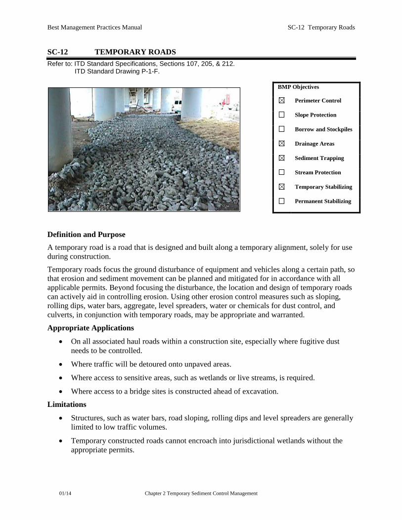
Definition and Purpose A temporary road is a road that is designed and built along a temporary alignment, solely for use during construction.
Temporary roads focus the ground disturbance of equipment and vehicles along a certain path, so that erosion and sediment movement can be planned and mitigated for in accordance with all applicable permits. Beyond focusing the disturbance, the location and design of temporary roads can actively aid in controlling erosion. Using other erosion control measures such as sloping, rolling dips, water bars, aggregate, level spreaders, water or chemicals for dust control, and culverts, in conjunction with temporary roads, may be appropriate and warranted.
Appropriate Applications
• On all associated haul roads within a construction site, especially where fugitive dust needs to be controlled.
• Where traffic will be detoured onto unpaved areas.
• Where access to sensitive areas, such as wetlands or live streams, is required.
• Where access to a bridge sites is constructed ahead of excavation.
Limitations
• Structures, such as water bars, road sloping, rolling dips and level spreaders are generally limited to low traffic volumes.
• Temporary constructed roads cannot encroach into jurisdictional wetlands without the appropriate permits.
BMP Objectives
Perimeter Control
Slope Protection
Borrow and Stockpiles
Drainage Areas
Sediment Trapping
Stream Protection
Temporary Stabilizing
Permanent Stabilizing

Best Management Practices Manual SC-12 Temporary Roads
01/14 Chapter 2 Temporary Sediment Control Management
Design Parameters
• Locate temporary roads to minimize erosion impacts. Design temporary roads to access sensitive areas at specific locations.
• At sites where traffic volumes are high, ensure that the entrance and roadway is wide enough for two vehicles to pass safely. Provide adequate turning radius at all entrances.
• Where appropriate, use geotextiles prior to placement of aggregate. Place aggregate at sufficient depth to support heavy equipment and protect existing pipe culverts from crushing.
• Route runoff from the road to a stabilized area (i.e., vegetated area, sediment basin or rip rap lined ditch).
Construction Guidelines
• Adequately slope temporary roads for good drainage, and install all other structures such as water bars, culverts, and rolling dips, according to plans and specifications.
• Do not use road sloping on grades steeper than 5 percent unless other structures are also used. If road is steeper than 5 percent, use gravel surfacing to minimize erosion, and slope the road to the side that has a ditch.
• Make field adjustments, as necessary, to ensure proper performance.
Maintenance and Inspection
• Conduct inspections as required by the NPDES permit or contract specifications.
• Make adjustments based on inspections and have accumulated sediment and other debris removed and disposed of properly.
• At the end of construction, re-contour to original slope and return to natural conditions using permanent erosion and sediment control BMPs. Remove or stabilize trapped sediment and permanently stabilize disturbed areas.
Best Management Practices Manual SC-13 Entrance/Outlet Tire Wash
01/14 Chapter 2 Temporary Sediment Control Management
SC-13 ENTRANCE/ OUTLET TIRE WASH Refer to: ITD Standard Specifications, Section 212. ITD Standard Drawing P-3-E.
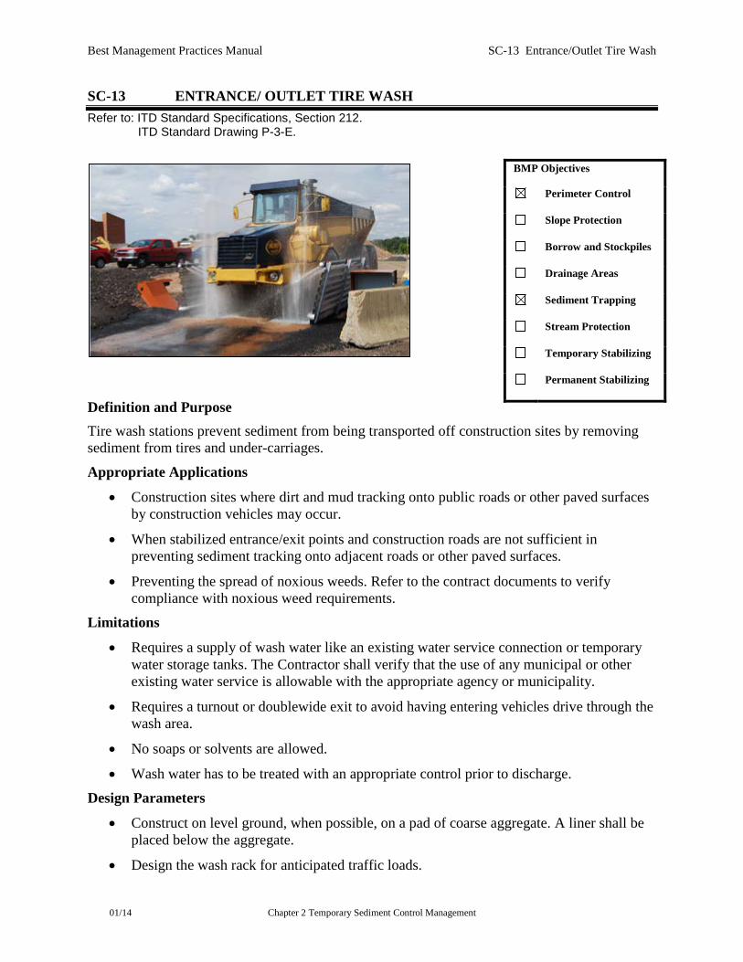
Definition and Purpose Tire wash stations prevent sediment from being transported off construction sites by removing sediment from tires and under-carriages.
Appropriate Applications
• Construction sites where dirt and mud tracking onto public roads or other paved surfaces by construction vehicles may occur.
• When stabilized entrance/exit points and construction roads are not sufficient in preventing sediment tracking onto adjacent roads or other paved surfaces.
• Preventing the spread of noxious weeds. Refer to the contract documents to verify compliance with noxious weed requirements.
Limitations
• Requires a supply of wash water like an existing water service connection or temporary water storage tanks. The Contractor shall verify that the use of any municipal or other existing water service is allowable with the appropriate agency or municipality.
• Requires a turnout or doublewide exit to avoid having entering vehicles drive through the wash area.
• No soaps or solvents are allowed.
• Wash water has to be treated with an appropriate control prior to discharge.
Design Parameters
• Construct on level ground, when possible, on a pad of coarse aggregate. A liner shall be placed below the aggregate.
• Design the wash rack for anticipated traffic loads.
BMP Objectives
Perimeter Control
Slope Protection
Borrow and Stockpiles
Drainage Areas
Sediment Trapping
Stream Protection
Temporary Stabilizing
Permanent Stabilizing

Best Management Practices Manual SC-13 Entrance/Outlet Tire Wash
01/14 Chapter 2 Temporary Sediment Control Management
• Provide a drainage ditch that will convey the runoff from the wash area to a sediment-trapping device. See SC-10 (Sediment Trap) for additional guidance regarding sediment traps. The drainage ditch shall be of sufficient grade, width, depth and adequately stabilized.
• Require that all employees, subcontractors, and others use the wash facility as appropriate.
• Implement SC-4 (Street Sweeping and Vacuuming) as needed.
Maintenance and Inspection
• Conduct inspections as required by the NPDES permit or contract specifications.
• Remove accumulated sediment in wash rack and/or sediment trap to maintain system performance and dispose of as required.