chapter 2 thermodynamics 2.1 the first law of thermodynamicsphysics.bounce1.info/bigbangscience/aqa...
TRANSCRIPT
AQA A2 Physics © Nelson Thornes 2009
Applied physics
Chapter 2 Thermodynamics
2.1 The first law of thermodynamics
Learning objectives:
What is the difference between heat and work?
How can we change the internal energy of a system?
What is an adiabatic change?
Heat transfer
Heat is energy transferred due to temperature difference. Heat transferred to an object either
causes the internal energy of the object to rise or allows the object to do work, or both. Energy
transformations often involve heating the surroundings. For example, a falling mass loses
potential energy. What happens to the potential energy? If the mass is accelerating as it falls, it
speeds up so it gains kinetic energy. Assuming air resistance is negligible, the loss of potential
energy equals the gain of kinetic energy of the object. If the mass then hits the floor, what
happens to its kinetic energy? Sound energy is produced and the atoms of the floor at the impact
point gain some energy as well. So the floor becomes just a little warmer as a result of the impact.
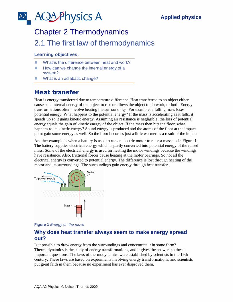
Another example is when a battery is used to run an electric motor to raise a mass, as in Figure 1.
The battery supplies electrical energy which is partly converted into potential energy of the raised
mass. Some of the electrical energy is used for heating the motor windings because the windings
have resistance. Also, frictional forces cause heating at the motor bearings. So not all the
electrical energy is converted to potential energy. The difference is lost through heating of the
motor and its surroundings. The surroundings gain energy through heat transfer.
Figure 1 Energy on the move
Why does heat transfer always seem to make energy spread out? Is it possible to draw energy from the surroundings and concentrate it in some form?
Thermodynamics is the study of energy transformations, and it gives the answers to these
important questions. The laws of thermodynamics were established by scientists in the 19th
century. These laws are based on experiments involving energy transformations, and scientists
put great faith in them because no experiment has ever disproved them.
AQA A2 Physics © Nelson Thornes 2009
Applied physics
The first law of thermodynamics states that heat energy supplied to a system either
increases the internal energy of the system or enables it to do work, or both.
Link
See A2 Physics A Topic 11.1 for internal energy.
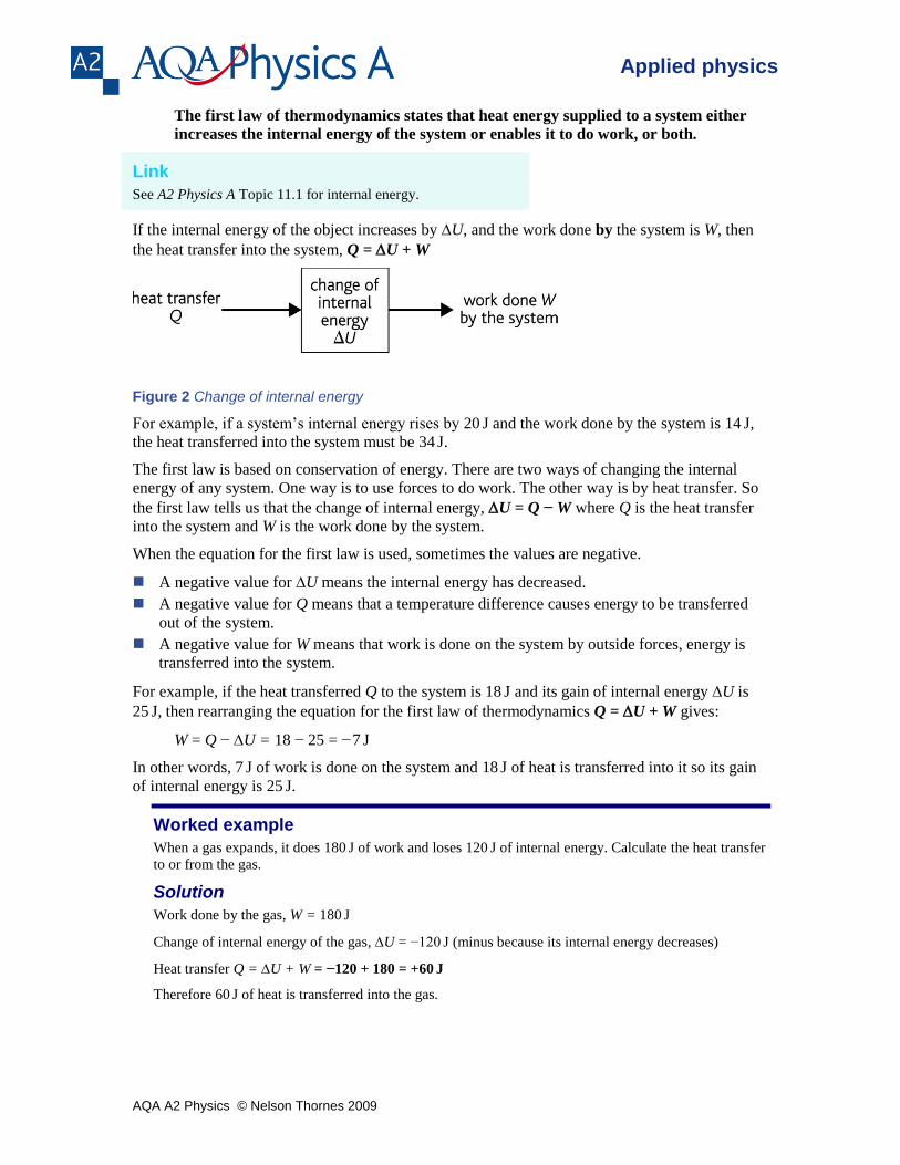
If the internal energy of the object increases by U, and the work done by the system is W, then
the heat transfer into the system, Q = U + W
Figure 2 Change of internal energy
For example, if a system’s internal energy rises by 20 J and the work done by the system is 14
J,
the heat transferred into the system must be 34 J.
The first law is based on conservation of energy. There are two ways of changing the internal
energy of any system. One way is to use forces to do work. The other way is by heat transfer. So
the first law tells us that the change of internal energy, U = Q − W where Q is the heat transfer
into the system and W is the work done by the system.
When the equation for the first law is used, sometimes the values are negative.
A negative value for U means the internal energy has decreased.
A negative value for Q means that a temperature difference causes energy to be transferred
out of the system.
A negative value for W means that work is done on the system by outside forces, energy is
transferred into the system.
For example, if the heat transferred Q to the system is 18 J and its gain of internal energy U is
25 J, then rearranging the equation for the first law of thermodynamics Q = U + W gives:
W = Q − U = 18 − 25 = −7 J
In other words, 7 J of work is done on the system and 18
J of heat is transferred into it so its gain
of internal energy is 25 J.
Worked example
When a gas expands, it does 180 J of work and loses 120
J of internal energy. Calculate the heat transfer
to or from the gas.
Solution
Work done by the gas, W = 180 J
Change of internal energy of the gas, U = −120 J (minus because its internal energy decreases)
Heat transfer Q = U + W = −120 + 180 = +60 J
Therefore 60 J of heat is transferred into the gas.
AQA A2 Physics © Nelson Thornes 2009
Applied physics
Thermodynamics at work
Stretching a rubber band 1 Stretch a rubber band quickly then hold it, still stretched, against your lower lip. It feels
warm. The internal energy of the rubber increases because you have done work on the rubber
band when you stretched it. The stretching was so rapid that heat transfer to the surroundings
was negligible. An energy transfer where no heat transfer occurs is called an adiabatic
change.
2 Keep the rubber band stretched against your lip and you should find that it cools to ‘lip’
temperature. Its internal energy falls due to heat transfer to the surroundings. No work is done
because there is no movement.
3 Now release the rubber band quickly, and put it unstretched against your lip again. You ought
to find that it becomes colder than ‘lip’ temperature as a result of unstretching. Its internal
energy has fallen because internal forces in the rubber do work as it unstretches. No heat
transfer occurs because the change is rapid.
4 Finally the unstretched rubber warms up to ‘lip’ temperature because heat transfer from the
surroundings increases its internal energy.
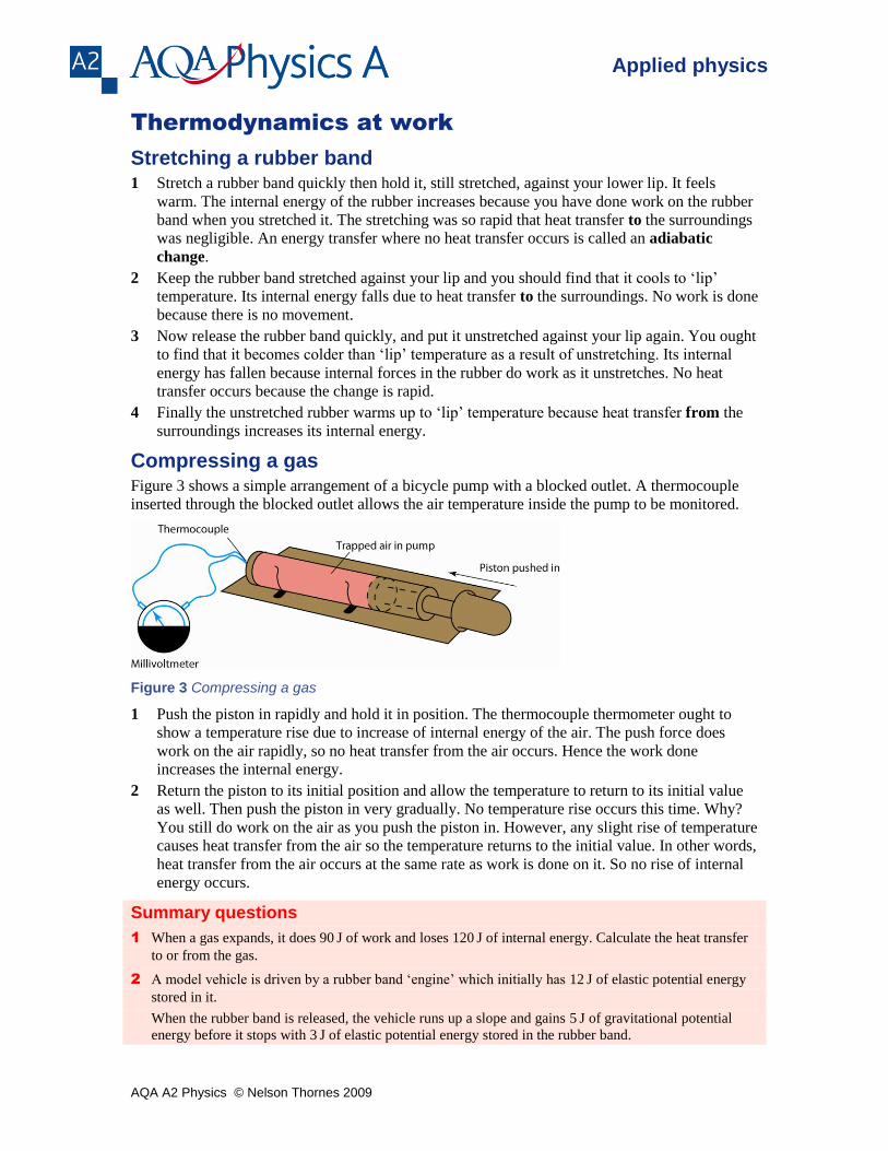
Compressing a gas Figure 3 shows a simple arrangement of a bicycle pump with a blocked outlet. A thermocouple
inserted through the blocked outlet allows the air temperature inside the pump to be monitored.
Figure 3 Compressing a gas
1 Push the piston in rapidly and hold it in position. The thermocouple thermometer ought to
show a temperature rise due to increase of internal energy of the air. The push force does
work on the air rapidly, so no heat transfer from the air occurs. Hence the work done
increases the internal energy.
2 Return the piston to its initial position and allow the temperature to return to its initial value
as well. Then push the piston in very gradually. No temperature rise occurs this time. Why?
You still do work on the air as you push the piston in. However, any slight rise of temperature
causes heat transfer from the air so the temperature returns to the initial value. In other words,
heat transfer from the air occurs at the same rate as work is done on it. So no rise of internal
energy occurs.
Summary questions
1 When a gas expands, it does 90 J of work and loses 120
J of internal energy. Calculate the heat transfer
to or from the gas.
2 A model vehicle is driven by a rubber band ‘engine’ which initially has 12 J of elastic potential energy
stored in it.
When the rubber band is released, the vehicle runs up a slope and gains 5 J of gravitational potential
energy before it stops with 3 J of elastic potential energy stored in the rubber band.
AQA A2 Physics © Nelson Thornes 2009
Applied physics
a Calculate the change of internal energy of the rubber band.
b Estimate:
i the work done by the rubber band
ii the heat transfer to or from the surroundings.
3 In a gas explosion, a gas is suddenly ignited then expands very rapidly.
a Explain why:
i the gas does no work when it ignites
ii no heat transfer occurs when the gas expands
b Complete the table on the right to indicate the energy transfers that
take place at each stage.
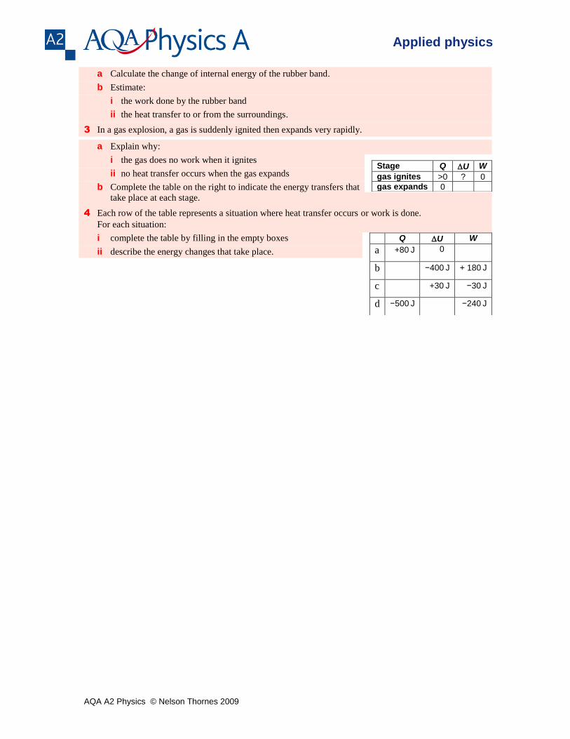
4 Each row of the table represents a situation where heat transfer occurs or work is done.
For each situation:
i complete the table by filling in the empty boxes
ii describe the energy changes that take place.
Q U W
a +80 J 0
b −400 J + 180
J
c +30 J −30
J
d −500 J −240
J
Stage Q U W
gas ignites >0 ? 0
gas expands 0
AQA A2 Physics © Nelson Thornes 2009
Applied physics
2.2 Thermodynamics of ideal gases
Learning objectives:
How much work is done by a gas when it expands?
How can we determine the work done by an ideal gas from a pressure–volume graph?
How can we calculate the pressure of a gas when it undergoes an adiabatic change?
Work done by an ideal gas
The internal energy U of an ideal gas is due to the kinetic energy of its molecules. No internal
forces of attraction exist between ‘ideal gas’ molecules so an ideal gas does not possess molecular
potential energy. To change the temperature of a gas, its internal energy U must be changed. To
do this, work must be done or heat must be transferred to or from the gas.
Link
See A2 Physics A Topic 12.2 to remind yourself about the
properties of an ideal gas.
Work is done on a gas when its volume is reduced (compressed). At constant volume, no work
is done because the forces due to pressure in the gas do not move the container walls. When a gas
is compressed, work is done on it by the applied forces which push the pressure forces back. Try
compressing the air in a bicycle pump by blocking the outlet and pushing the piston in rapidly.
Work is done by a gas when it expands. When a gas expands, the forces due to its pressure
pushes back the container walls, as in Figure 1. So the gas does work when it expands. For
example, when the valve on a cylinder of carbon dioxide gas is released, the cylinder outlet
releases a high-pressure jet of CO2 gas into the air. The gas does work to expand and push back
the air. The CO2 uses up so much of its internal energy to expand that it cools and solidifies. You
may have seen solid CO2 produced in this way for use in cloud chambers.
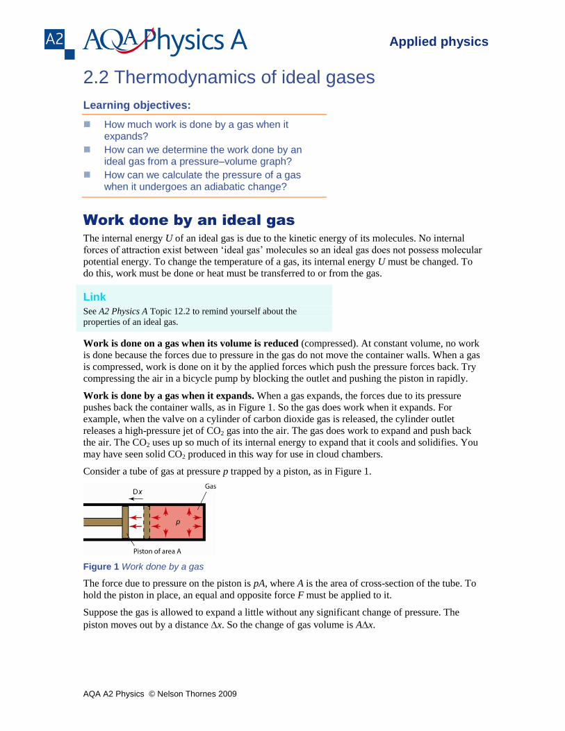
Consider a tube of gas at pressure p trapped by a piston, as in Figure 1.
Figure 1 Work done by a gas
The force due to pressure on the piston is pA, where A is the area of cross-section of the tube. To
hold the piston in place, an equal and opposite force F must be applied to it.
Suppose the gas is allowed to expand a little without any significant change of pressure. The
piston moves out by a distance x. So the change of gas volume is Ax.
AQA A2 Physics © Nelson Thornes 2009
Applied physics
The work done by the gas is given by force × distance moved = Fx = pAx = pV since
Ax = the volume change, V. Therefore, when a gas expands and its volume increases by V at
constant pressure p.
work done by the gas, W = pV
For example, if the volume increases from 0.100 m
3 to 0.102
m
3 at a pressure of 10
5 Pa, the work
done by the gas is 105 × 0.002 = 200
J.
Note
If the volume had decreased from 0.100 m
3 to 0.098
m
3, the volume change would have been
−0.002 m
3, giving work done by the gas equal to −200
J. In this case, the − sign indicates energy
transferred to the gas.
Adiabatic changes of an ideal gas
An adiabatic change is defined as one which occurs without heat transfer. A gas can be
compressed adiabatically by reducing its volume rapidly. The change is then too fast for
measurable heat transfer. Another way is to insulate the gas container so heat transfer cannot
occur.
For any adiabatic change of an ideal gas, it can be shown that the gas pressure p and the gas
volume V are given by the following equation which is referred to as the adiabatic equation for
an ideal gas.
constant γ Vp
where , referred to as the adiabatic constant, has a value that depends on the number of atoms in
each molecule of the gas.
Notes
1 Proof of this equation is not required. You do need to be able to use the equation. An outline
of the proof is provided in Appendix B to give a deeper understanding of the principles that
underlie the equation.
2 You will be given the value of in an examination question. For a monatomic gas, = 1.67;
for a diatomic gas, = 1.40; for a polyatomic gas, = 1.33.
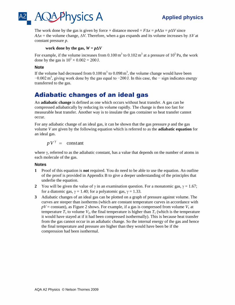
3 Adiabatic changes of an ideal gas can be plotted on a graph of pressure against volume. The
curves are steeper than isotherms (which are constant temperature curves in accordance with
pV = constant), as Figure 2 shows. For example, if a gas is compressed from volume V1 at
temperature T1 to volume V2, the final temperature is higher than T1 (which is the temperature
it would have stayed at if it had been compressed isothermally). This is because heat transfer
from the gas cannot occur in an adiabatic change. So the internal energy of the gas and hence
the final temperature and pressure are higher than they would have been be if the
compression had been isothermal.

AQA A2 Physics © Nelson Thornes 2009
Applied physics
Figure 2 Adiabatic curves
Worked example
A cylinder contains 0.24 m
3 of air at a pressure of 100
kPa and a temperature of 290
K. The air in the
cylinder is compressed adiabatically by means of a piston to a volume of 0.11 m
3. Calculate the pressure
and the temperature of the air immediately after it has been compressed.
= 1.40 for air
Solution
To find the final pressure p, applying pV = constant to the initial and final pressures and volumes gives
p × 0.111.4
= 100 × 103 × 0.24
1.4 where p is the final pressure.
Therefore p = 100 × 103 ×
4.1
11.0
24.0
= 300 × 10
3 Pa = 300
kPa
To find the final temperature T, applying pV = nRT in the form T
pV = constant (= nR) gives
290
24.01010011.010300 33
T
Rearranging this equation gives K40024.010100
29011.0103003
3
T
Pressure against volume curves
For a fixed mass of an ideal gas, the pressure, volume and temperature must always conform to
the ideal gas law pV = nRT. Pressure against volume curves are a helpful way to show the
changes in a gas.
Link
See A2 Physics A Topic 12.2 for the ideal gas law.
Figure 2 shows three particular changes in which a fixed mass of gas is compressed from volume
V1 to a smaller volume V2:
At constant pressure, the change is represented by a horizontal line from V1 to V2.
AQA A2 Physics © Nelson Thornes 2009
Applied physics
At constant temperature (i.e. an isothermal change), the change is represented by a curve in
accordance with Boyle’s law (i.e. pressure p is inversely proportional to the volume V). Thus the
equation for the curve is V
kp where k = nRT.
For no heat transfer (i.e. an adiabatic change), the change is a curve that is steeper than the
isothermal curve. The equation for an adiabatic curve is the adiabatic equation constant. γ Vp
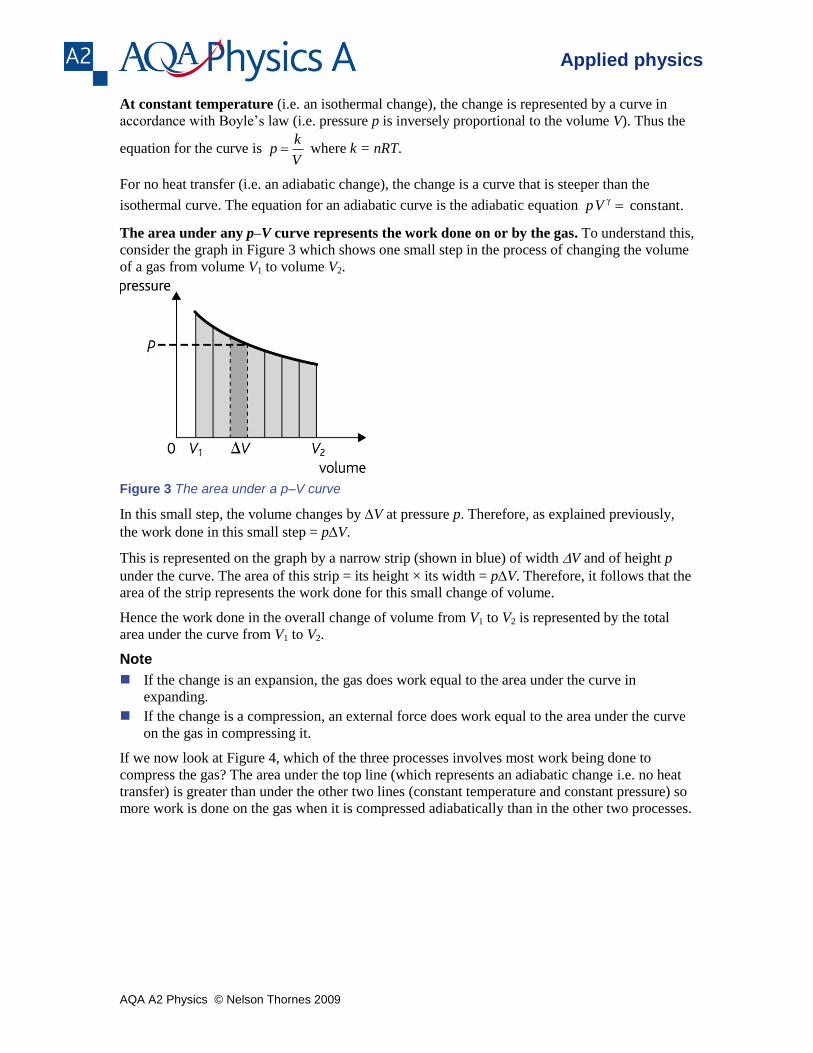
The area under any p–V curve represents the work done on or by the gas. To understand this,
consider the graph in Figure 3 which shows one small step in the process of changing the volume
of a gas from volume V1 to volume V2.
Figure 3 The area under a p–V curve
In this small step, the volume changes by V at pressure p. Therefore, as explained previously,
the work done in this small step = pV.
This is represented on the graph by a narrow strip (shown in blue) of width V and of height p
under the curve. The area of this strip = its height × its width = pV. Therefore, it follows that the
area of the strip represents the work done for this small change of volume.
Hence the work done in the overall change of volume from V1 to V2 is represented by the total
area under the curve from V1 to V2.
Note
If the change is an expansion, the gas does work equal to the area under the curve in
expanding.
If the change is a compression, an external force does work equal to the area under the curve
on the gas in compressing it.
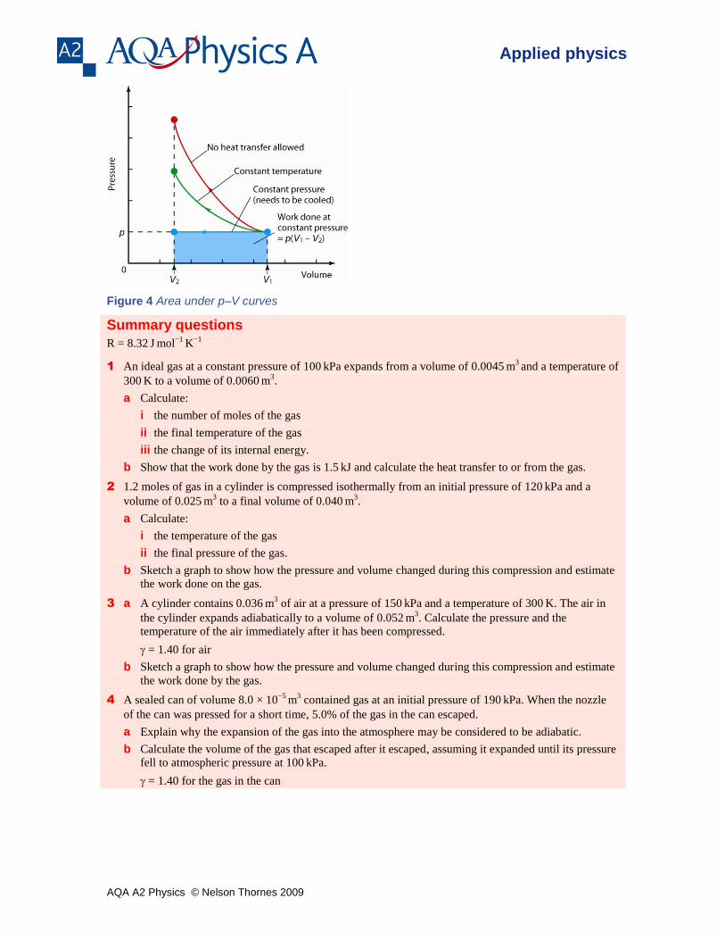
If we now look at Figure 4, which of the three processes involves most work being done to
compress the gas? The area under the top line (which represents an adiabatic change i.e. no heat
transfer) is greater than under the other two lines (constant temperature and constant pressure) so
more work is done on the gas when it is compressed adiabatically than in the other two processes.
AQA A2 Physics © Nelson Thornes 2009
Applied physics
Figure 4 Area under p–V curves
Summary questions
R = 8.32 J
mol
−1 K
−1
1 An ideal gas at a constant pressure of 100 kPa expands from a volume of 0.0045
m
3 and a temperature of
300 K to a volume of 0.0060
m
3.
a Calculate:
i the number of moles of the gas
ii the final temperature of the gas
iii the change of its internal energy.
b Show that the work done by the gas is 1.5 kJ and calculate the heat transfer to or from the gas.
2 1.2 moles of gas in a cylinder is compressed isothermally from an initial pressure of 120 kPa and a
volume of 0.025 m
3 to a final volume of 0.040
m
3.
a Calculate:
i the temperature of the gas
ii the final pressure of the gas.
b Sketch a graph to show how the pressure and volume changed during this compression and estimate
the work done on the gas.
3 a A cylinder contains 0.036 m
3 of air at a pressure of 150
kPa and a temperature of 300
K. The air in
the cylinder expands adiabatically to a volume of 0.052 m
3. Calculate the pressure and the
temperature of the air immediately after it has been compressed.
= 1.40 for air
b Sketch a graph to show how the pressure and volume changed during this compression and estimate
the work done by the gas.
4 A sealed can of volume 8.0 × 10⁻⁵
m3 contained gas at an initial pressure of 190
kPa. When the nozzle
of the can was pressed for a short time, 5.0% of the gas in the can escaped.
a Explain why the expansion of the gas into the atmosphere may be considered to be adiabatic.
b Calculate the volume of the gas that escaped after it escaped, assuming it expanded until its pressure
fell to atmospheric pressure at 100 kPa.
= 1.40 for the gas in the can
AQA A2 Physics © Nelson Thornes 2009
Applied physics
2.3 Heat engines
Learning objectives:
Why does a heat engine always waste energy?
What is an indicator diagram and how do we use it to find work done?
What do we mean by overall efficiency?
The second law of thermodynamics
A heat engine is designed to do useful work which is supplied to it as a result of heat transfer. A
steam engine or a car engine does work as long as it has fuel. Heat transfer from the burning fuel
to the engine takes place, allowing the engine to do work. The internal energy of the engine does
not change, provided its temperature is steady. So heat transfer to the engine is equal to the work
done by the engine + the heat losses to the surroundings.
Qin = W + Qout
where:
Qin = heat transfer to the engine
W = work done by the engine
Qout = heat losses to the surroundings.
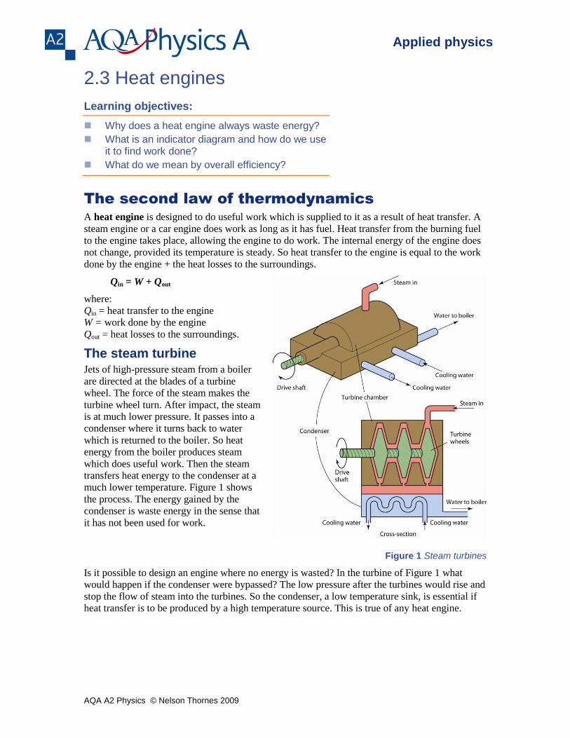
The steam turbine Jets of high-pressure steam from a boiler
are directed at the blades of a turbine
wheel. The force of the steam makes the
turbine wheel turn. After impact, the steam
is at much lower pressure. It passes into a
condenser where it turns back to water
which is returned to the boiler. So heat
energy from the boiler produces steam
which does useful work. Then the steam
transfers heat energy to the condenser at a
much lower temperature. Figure 1 shows
the process. The energy gained by the
condenser is waste energy in the sense that
it has not been used for work.
Figure 1 Steam turbines
Is it possible to design an engine where no energy is wasted? In the turbine of Figure 1 what
would happen if the condenser were bypassed? The low pressure after the turbines would rise and
stop the flow of steam into the turbines. So the condenser, a low temperature sink, is essential if
heat transfer is to be produced by a high temperature source. This is true of any heat engine.
AQA A2 Physics © Nelson Thornes 2009
Applied physics
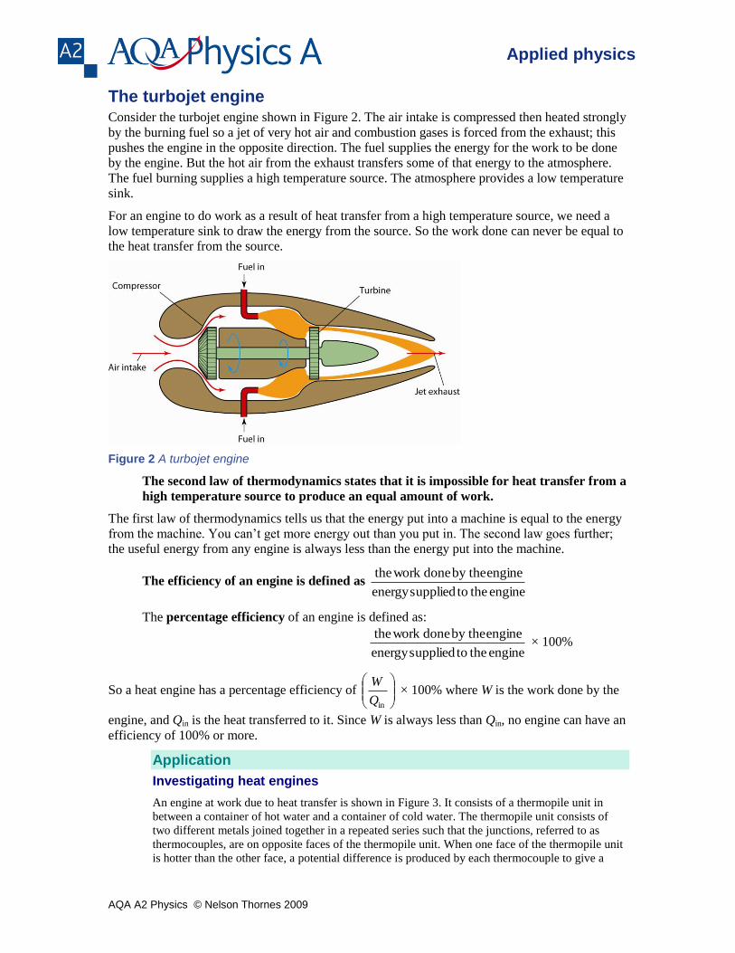
The turbojet engine Consider the turbojet engine shown in Figure 2. The air intake is compressed then heated strongly
by the burning fuel so a jet of very hot air and combustion gases is forced from the exhaust; this
pushes the engine in the opposite direction. The fuel supplies the energy for the work to be done
by the engine. But the hot air from the exhaust transfers some of that energy to the atmosphere.
The fuel burning supplies a high temperature source. The atmosphere provides a low temperature
sink.
For an engine to do work as a result of heat transfer from a high temperature source, we need a
low temperature sink to draw the energy from the source. So the work done can never be equal to
the heat transfer from the source.
Figure 2 A turbojet engine
The second law of thermodynamics states that it is impossible for heat transfer from a
high temperature source to produce an equal amount of work.
The first law of thermodynamics tells us that the energy put into a machine is equal to the energy
from the machine. You can’t get more energy out than you put in. The second law goes further;
the useful energy from any engine is always less than the energy put into the machine.
The efficiency of an engine is defined as engine the tosuppliedenergy
engine by the done work the
The percentage efficiency of an engine is defined as:
engine the tosuppliedenergy
engine by the done work the × 100%
So a heat engine has a percentage efficiency of
inQ
W × 100% where W is the work done by the
engine, and Qin is the heat transferred to it. Since W is always less than Qin, no engine can have an
efficiency of 100% or more.
Application
Investigating heat engines
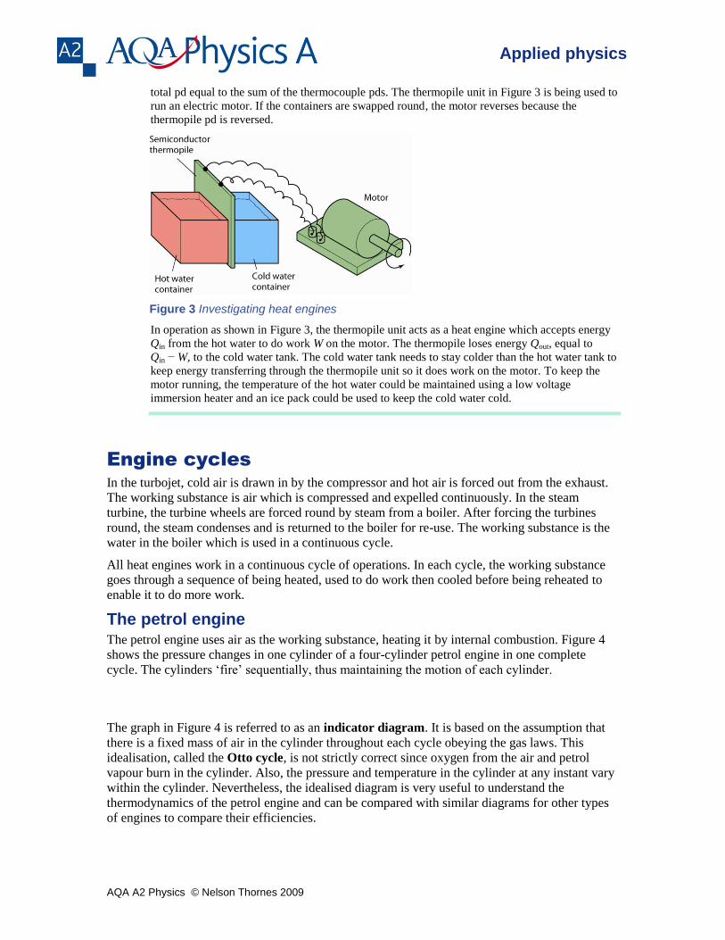
An engine at work due to heat transfer is shown in Figure 3. It consists of a thermopile unit in
between a container of hot water and a container of cold water. The thermopile unit consists of
two different metals joined together in a repeated series such that the junctions, referred to as
thermocouples, are on opposite faces of the thermopile unit. When one face of the thermopile unit
is hotter than the other face, a potential difference is produced by each thermocouple to give a
AQA A2 Physics © Nelson Thornes 2009
Applied physics
total pd equal to the sum of the thermocouple pds. The thermopile unit in Figure 3 is being used to
run an electric motor. If the containers are swapped round, the motor reverses because the
thermopile pd is reversed.
Figure 3 Investigating heat engines
In operation as shown in Figure 3, the thermopile unit acts as a heat engine which accepts energy
Qin from the hot water to do work W on the motor. The thermopile loses energy Qout, equal to
Qin − W, to the cold water tank. The cold water tank needs to stay colder than the hot water tank to
keep energy transferring through the thermopile unit so it does work on the motor. To keep the
motor running, the temperature of the hot water could be maintained using a low voltage
immersion heater and an ice pack could be used to keep the cold water cold.
Engine cycles
In the turbojet, cold air is drawn in by the compressor and hot air is forced out from the exhaust.
The working substance is air which is compressed and expelled continuously. In the steam
turbine, the turbine wheels are forced round by steam from a boiler. After forcing the turbines
round, the steam condenses and is returned to the boiler for re-use. The working substance is the
water in the boiler which is used in a continuous cycle.
All heat engines work in a continuous cycle of operations. In each cycle, the working substance
goes through a sequence of being heated, used to do work then cooled before being reheated to
enable it to do more work.
The petrol engine The petrol engine uses air as the working substance, heating it by internal combustion. Figure 4
shows the pressure changes in one cylinder of a four-cylinder petrol engine in one complete
cycle. The cylinders ‘fire’ sequentially, thus maintaining the motion of each cylinder.
The graph in Figure 4 is referred to as an indicator diagram. It is based on the assumption that
there is a fixed mass of air in the cylinder throughout each cycle obeying the gas laws. This
idealisation, called the Otto cycle, is not strictly correct since oxygen from the air and petrol
vapour burn in the cylinder. Also, the pressure and temperature in the cylinder at any instant vary
within the cylinder. Nevertheless, the idealised diagram is very useful to understand the
thermodynamics of the petrol engine and can be compared with similar diagrams for other types
of engines to compare their efficiencies.
AQA A2 Physics © Nelson Thornes 2009
Applied physics
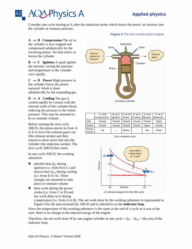
Consider one cycle starting at A after the induction stroke which draws the petrol–air mixture into
the cylinder at constant pressure:
Figure 4 The four-stroke petrol engine
A B Compression The air in
the cylinder is now trapped and
compressed adiabatically by the
incoming piston. No heat enters or
leaves the cylinder.
B C Ignition A spark ignites
the mixture, raising the pressure
and temperature in the cylinder
very rapidly.
C D Power High pressure in
the cylinder forces the piston
outward. Work is done
adiabatically by the expanding gas.
D A Cooling The gas is
cooled rapidly by contact with the
internal walls of the cylinder block,
reducing the pressure to the initial
pressure. This may be assumed to
be at constant volume.
Before starting the next cycle
ABCD, the piston moves in from A
to E to force the exhaust gases out
(the exhaust stroke) and then
returns to draw more fuel into the
cylinder (the induction stroke). The
next cycle ABCD then starts.
In one cycle ABCD, the working
substance:
absorbs heat Qin during
ignition (i.e. from B to C) and
rejects heat Qout during cooling
(i.e. from D to A). These
changes are assumed to take
place at constant volume
does work during the power
stroke (i.e. from C to D) and
has work done on it during
compression (i.e. from A to B). The net work done by the working substance is represented in
Figure 4 by the area enclosed by ABCD and is referred to as the indicator loop.
Since the temperature of the working substance is the same at the end of a cycle as it was at the
start, there is no change in the internal energy of the engine.
Therefore, the net work done W by one engine cylinder in one cycle = Qin − Qout = the area of the
indicator loop.
AQA A2 Physics © Nelson Thornes 2009
Applied physics
The indicated power of the engine
= the rate of net work done by the engine
= area of indicator loop × number of cycles per second × number of cylinders
The input power to the engine
= the calorific value of the fuel (in J kg
−1) × the fuel flow rate (in kg
s
−1)
where the calorific value of the fuel is the energy released per unit mass of fuel when the fuel is
burned.
Therefore, as the thermal efficiency of the engine = secondper suppliedenergy
secondper donework
the thermal efficiency = combustion fuel frompower input
power indicated
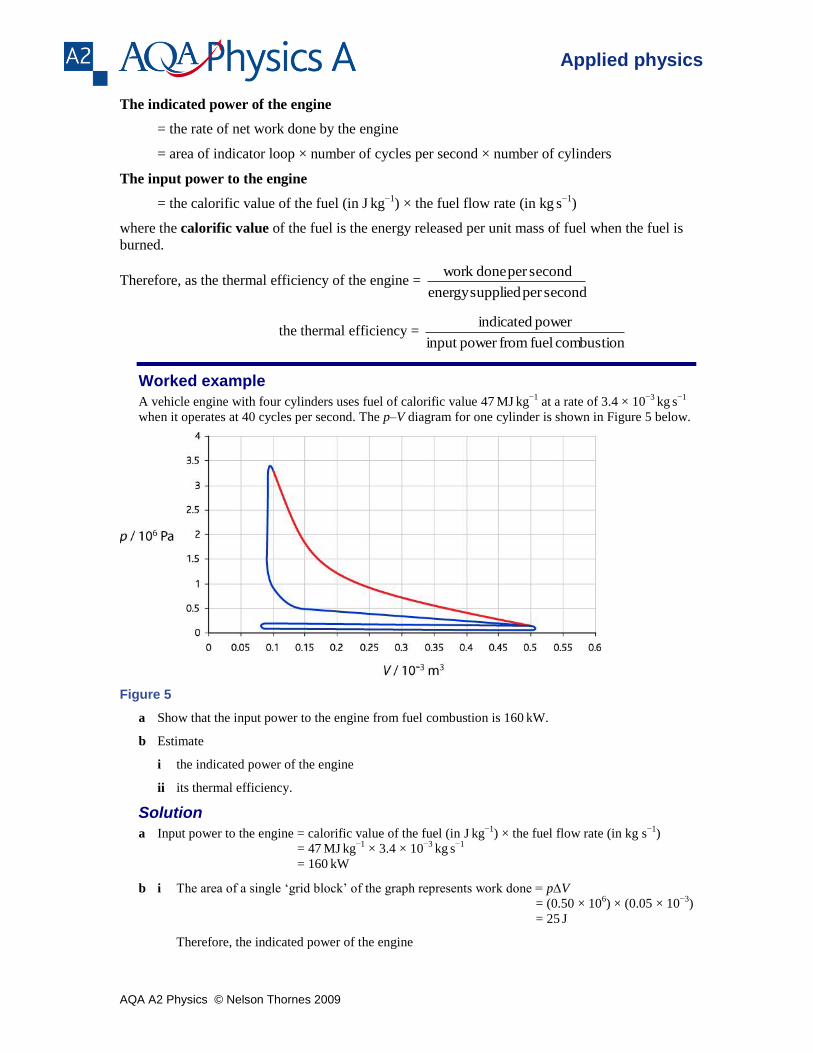
Worked example
A vehicle engine with four cylinders uses fuel of calorific value 47 MJ
kg
−1 at a rate of 3.4 × 10
−3 kg
s
−1
when it operates at 40 cycles per second. The p–V diagram for one cylinder is shown in Figure 5 below.
Figure 5
a Show that the input power to the engine from fuel combustion is 160 kW.
b Estimate
i the indicated power of the engine
ii its thermal efficiency.
Solution
a Input power to the engine = calorific value of the fuel (in J kg
−1) × the fuel flow rate (in kg s
−1)
= 47 MJ
kg
−1 × 3.4 × 10
−3 kg
s
−1
= 160 kW
b i The area of a single ‘grid block’ of the graph represents work done = pV
= (0.50 × 106) × (0.05 × 10
−3)
= 25 J
Therefore, the indicated power of the engine
AQA A2 Physics © Nelson Thornes 2009
Applied physics
= indicator loop area × number of cycles per second × number of cylinders
= 12 blocks × 25 J per block × 40
s
−1 × 4 cylinders
= 48 kW
ii Thermal efficiency = combustion fuel frompower input
power indicated =
160
48 = 0.3
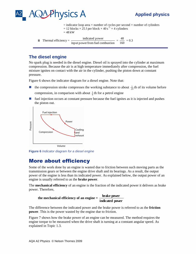
The diesel engine No spark plug is needed in the diesel engine. Diesel oil is sprayed into the cylinder at maximum
compression. Because the air is at high temperature immediately after compression, the fuel
mixture ignites on contact with the air in the cylinder, pushing the piston down at constant
pressure.
Figure 6 shows the indicator diagram for a diesel engine. Note that:
the compression stroke compresses the working substance to about 201 th of its volume before
compression, in comparison with about 91 th for a petrol engine
fuel injection occurs at constant pressure because the fuel ignites as it is injected and pushes
the piston out.
Figure 6 Indicator diagram for a diesel engine
More about efficiency
Some of the work done by an engine is wasted due to friction between such moving parts as the
transmission gears or between the engine drive shaft and its bearings. As a result, the output
power of the engine is less than its indicated power. As explained below, the output power of an
engine is usually referred to as the brake power.
The mechanical efficiency of an engine is the fraction of the indicated power it delivers as brake
power. Therefore,
the mechanical efficiency of an engine = power indicated
power brake
The difference between the indicated power and the brake power is referred to as the friction
power. This is the power wasted by the engine due to friction.
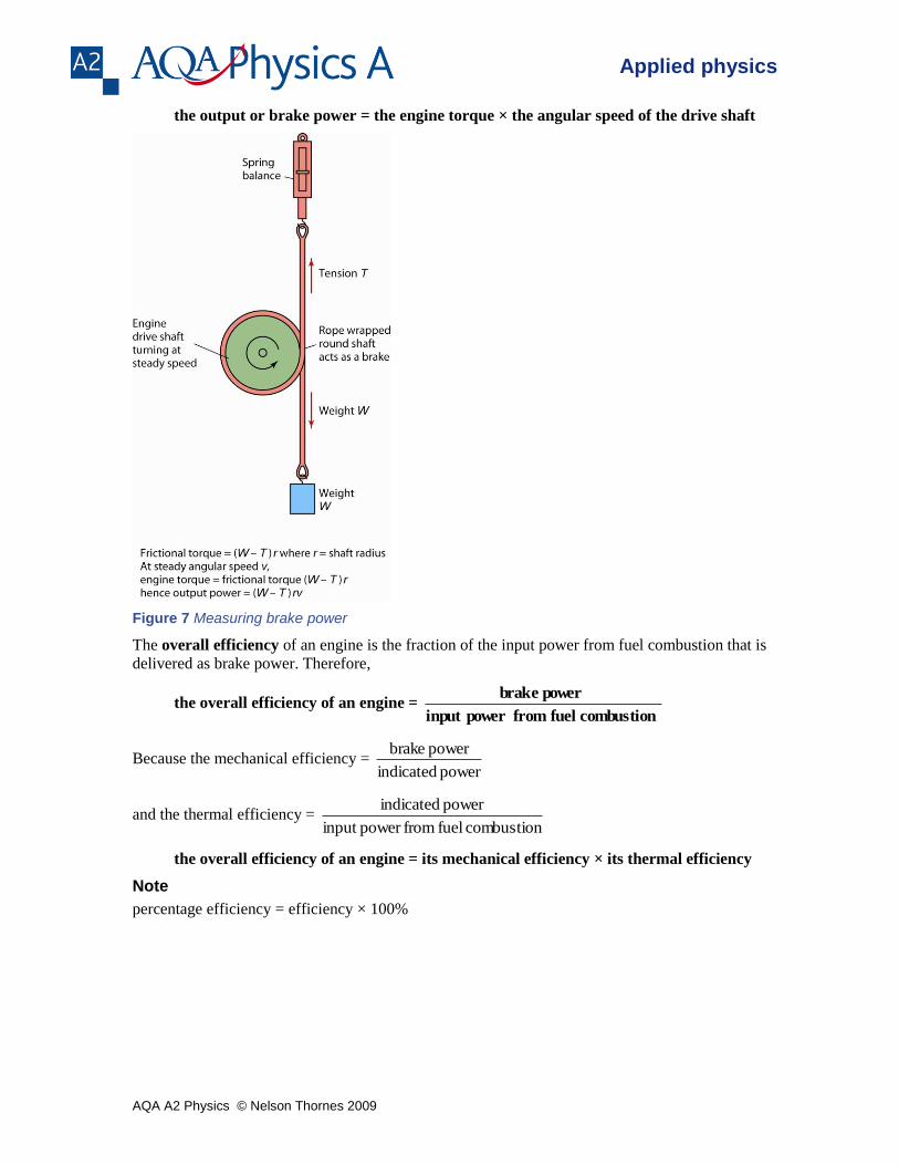
Figure 7 shows how the brake power of an engine can be measured. The method requires the
engine torque to be measured when the drive shaft is turning at a constant angular speed. As
explained in Topic 1.3.
AQA A2 Physics © Nelson Thornes 2009
Applied physics
the output or brake power = the engine torque × the angular speed of the drive shaft
Figure 7 Measuring brake power
The overall efficiency of an engine is the fraction of the input power from fuel combustion that is
delivered as brake power. Therefore,
the overall efficiency of an engine = combustion fuel frompower input
power brake
Because the mechanical efficiency = power indicated
power brake
and the thermal efficiency = combustion fuel frompower input
power indicated
the overall efficiency of an engine = its mechanical efficiency × its thermal efficiency
Note
percentage efficiency = efficiency × 100%
AQA A2 Physics © Nelson Thornes 2009
Applied physics
Summary questions
1 Explain qualitatively why the efficiency of a heat engine is less than 100%.
2 A vehicle engine with 4 cylinders uses fuel of calorific value 43 MJ
kg
−1 at a rate of 3.7 × 10
−3 kg
s
−1
when it operates at 48 cycles per second. In this situation, the work done by each cylinder in each
engine cycle is 0.23 kW.
Calculate:
a the input power from the engine
b the percentage thermal efficiency of the engine.
3 With the aid of indicator diagrams, describe how an engine cycle of a diesel engine differs from that of
a petrol engine.
4 A certain jet engine does 500 kJ of work for every kilogram of air that passes through it. When the mass
flow rate through the engine is 9.6 kg
s
−1, frictional heating in the engine causes a total power loss of
400 kW.
a Calculate:
i the work done per second by the engine
ii the output power of the engine.
b The engine uses fuel of calorific value 42 MJ
kg
−1 at a rate of 0.31
kg
s
−1.. Calculate:
i the input power to the engine
ii the overall efficiency of the engine.
AQA A2 Physics © Nelson Thornes 2009
Applied physics
2.4 Efficiency and thermodynamics
Learning objectives:
What is a reversible heat engine?
How efficient can a heat engine be in theory?
What are the main reasons why an engine does not achieve its theoretical efficiency?
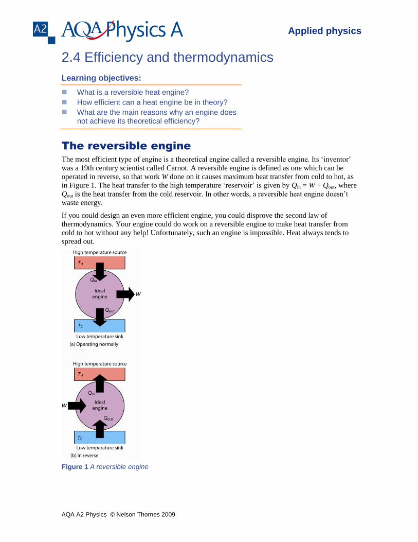
The reversible engine
The most efficient type of engine is a theoretical engine called a reversible engine. Its ‘inventor’
was a 19th century scientist called Carnot. A reversible engine is defined as one which can be
operated in reverse, so that work W done on it causes maximum heat transfer from cold to hot, as
in Figure 1. The heat transfer to the high temperature ‘reservoir’ is given by Qin = W + Qout, where
Qout is the heat transfer from the cold reservoir. In other words, a reversible heat engine doesn’t
waste energy.
If you could design an even more efficient engine, you could disprove the second law of
thermodynamics. Your engine could do work on a reversible engine to make heat transfer from
cold to hot without any help! Unfortunately, such an engine is impossible. Heat always tends to
spread out.
Figure 1 A reversible engine
AQA A2 Physics © Nelson Thornes 2009
Applied physics
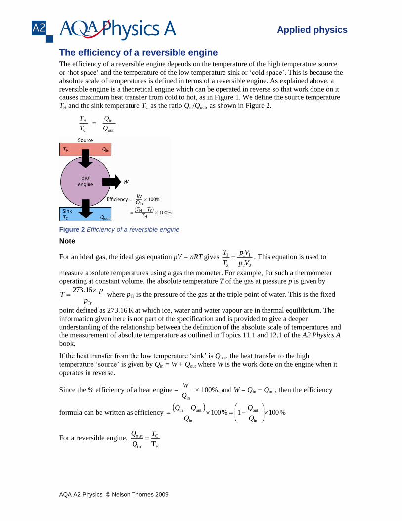
The efficiency of a reversible engine The efficiency of a reversible engine depends on the temperature of the high temperature source
or ‘hot space’ and the temperature of the low temperature sink or ‘cold space’. This is because the
absolute scale of temperatures is defined in terms of a reversible engine. As explained above, a
reversible engine is a theoretical engine which can be operated in reverse so that work done on it
causes maximum heat transfer from cold to hot, as in Figure 1. We define the source temperature
TH and the sink temperature TC as the ratio Qin/Qout, as shown in Figure 2.
out
in
C
H Q
Q
T
T
Figure 2 Efficiency of a reversible engine
Note
For an ideal gas, the ideal gas equation pV = nRT gives 22
11
2
1
Vp
Vp
T
T . This equation is used to
measure absolute temperatures using a gas thermometer. For example, for such a thermometer
operating at constant volume, the absolute temperature T of the gas at pressure p is given by
Tr
16.273
p
pT
where pTr is the pressure of the gas at the triple point of water. This is the fixed
point defined as 273.16 K at which ice, water and water vapour are in thermal equilibrium. The
information given here is not part of the specification and is provided to give a deeper
understanding of the relationship between the definition of the absolute scale of temperatures and
the measurement of absolute temperature as outlined in Topics 11.1 and 12.1 of the A2 Physics A
book.
If the heat transfer from the low temperature ‘sink’ is Qout, the heat transfer to the high
temperature ‘source’ is given by Qin = W + Qout where W is the work done on the engine when it
operates in reverse.
Since the % efficiency of a heat engine = inQ
W × 100%, and W = Qin − Qout, then the efficiency
formula can be written as efficiency
%1001%100in
out
in
outin
Q
Q
Q
For a reversible engine, H
C
in
out
T
T
Q
Q
AQA A2 Physics © Nelson Thornes 2009
Applied physics
Therefore, the % efficiency of a reversible engine
%100%1001H
CH
H
C
T
TT
T
T
Because a reversible engine is the most efficient engine possible, the maximum possible
efficiency of any heat engine operating between a heat source and a heat sink at temperatures TH
and TC respectively is given by
maximum possible efficiency
%100H
CH
T
TT
For example:
a thermopile engine operating between 373 K and 273
K can never have an efficiency greater
than 27%
an engine operating between temperatures of 700 K and 300
K can never have an efficiency
greater than 56%.
The only way any engine could be made 100% efficient would be to make the sink at absolute
zero (TC = 0), and that is impossible.
Energy becomes less and less useful when it is transferred because real engines operate at less
than maximum efficiency.
A reversible engine does work W by taking energy Qin as heat transfer from a high
temperature source TH. The engine has to supply energy Qout to a low temperature sink TC to
enable it to do work. Suppose we use the engine to raise a weight so the work done is stored
as gravitational potential energy of the weight. We can then use the stored energy to do work
W on the heat engine, operating it in reverse. The reversible engine would then transfer
energy Qin back to TH, taking energy Qout from TC. Our operations have taken us back to the
starting point, as if nothing had happened. No energy has been wasted. This can only happen
with a reversible engine.
Now suppose we use a real engine instead. It does less work for the same heat transfer Qin
from the high temperature source as its efficiency is less than the reversible engine.
Therefore, when it operates in reverse, it cannot return energy Qin to the high temperature
source. Its efficiency must be less than that of a reversible engine under the same conditions.
Efficiency in practice As explained in the previous topic, the overall efficiency of an engine = its mechanical efficiency
× its thermal efficiency. Mechanical efficiency and thermal efficiency are both lower in practice
than in theory for the following reasons:
Thermal efficiency in theory depends on the temperatures of the heat ‘source’ and the heat ‘sink’
as explained in the next topic. Typical theoretical values of thermal efficiency are 58% for a
petrol engine and 65% for a diesel engine. In practice, a typical petrol engine has a thermal
efficiency of about 30% in practice in comparison with about 35% for a typical diesel engine. The
main reasons why thermal efficiency values are much lower in practice than in theory are:
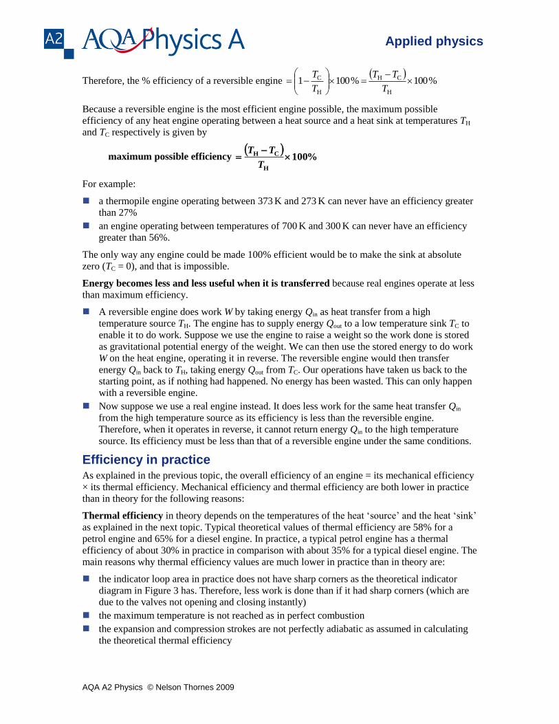
the indicator loop area in practice does not have sharp corners as the theoretical indicator
diagram in Figure 3 has. Therefore, less work is done than if it had sharp corners (which are
due to the valves not opening and closing instantly)
the maximum temperature is not reached as in perfect combustion
the expansion and compression strokes are not perfectly adiabatic as assumed in calculating
the theoretical thermal efficiency
AQA A2 Physics © Nelson Thornes 2009
Applied physics
work is done by the engine to bring about the induction and exhaust strokes.
AB BC CD DA AE EA
compression ignition power cooling exhaust induction
Figure 3 The indicator diagram for the Otto cycle
Mechanical efficiency is less than 100% because:
friction between the moving parts in the engine cannot be eliminated
oil used to lubricate the bearings in an engine are viscous which means they cause some
resistance to the motion of the moving parts.
Application
More about the thermodynamics of a petrol engine
In a petrol engine, energy from the fuel in a cylinder is released as heat when the fuel is ignited by
a spark.
The heat source is the ignited fuel in the cylinder hence the engine is referred to as an internal
combustion engine. The heat transfer Qin from the ignited fuel causes an increase of temperature
in the cylinder when ignition occurs in proportion to the heat transferred. Hence, with reference to
the indicator diagram in Figure 3 (where TA, TB, TC, TD = temperatures at A, B, C, D).
Qin (TC − TB)
The heat sink is the engine casing which transfers heat from the cylinders to the surroundings.
This heat transfer Qout occurs during cooling after the power stroke and before the exhaust stroke.
The heat transfer Qout causes a decrease of temperature in the cylinder in proportion to the heat
transferred. Hence, with reference to the indicator diagram in Figure 3
Qout (TD − TA)
Since the % efficiency of a heat engine = %100
in
outin
Q
= %1001
in
out
Q
Q
Therefore the theoretical % efficiency of a petrol engine = %1001BC
AD
TT
TT
Using the adiabatic equation for an ideal gas, it can be shown that the temperature difference ratio
AQA A2 Physics © Nelson Thornes 2009
Applied physics
BC
AD
TT
TT
is equal to r
−0.4, where r is the ratio of the
volumeminimum
volumemaximum of the cylinder, referred to
as the compression ratio.
A typical value of r = 9 gives a value of r−0.4
equal to 0.42 and therefore a theoretical thermal
efficiency of 58%. In comparison, for the reasons listed in Topic 2.3, the % efficiency of a real
petrol engine is about 30%.
Application
Combined heat and power (CHP) stations
In an electricity power station, turbine engines are used to drive electricity generators. The engines
need to be cooled to keep them working otherwise the steam used to drive them would not
condense. Cooling is achieved by pumping water through the engine block. The water is heated as
it passes through the engine block. In CHP stations, this hot water is used to heat local buildings.
Taking account of this use of heat that would otherwise be wasted, CHP stations are more
efficient than non-CHP stations that generate equal electrical power.
Summary questions
1 A thermopile engine operating between water tanks at temperatures of 20°C and 80°C delivers 4 W of
electrical power to an electric motor and supplies heat to the cold water tank at a rate of 36 J
s
−1.
a Calculate:
i the heat per second transferred from the hot water tank
ii the efficiency of the engine.
b Calculate the maximum possible efficiency of the engine in this situation.
2 In a geothermal power station, a heat engine uses hot water from below the surface as a heat source and
cold sea water as a heat sink. The temperature of the hot water is 79°C. When the sea water is at 9°C,
the heat engine has a power output of 3.2 MW. Calculate:
a the theoretical efficiency of the heat engine
b the rate at which the heat engine extracts heat from the hot water, assuming the engine operates at its
theoretical efficiency.
3 A gas-powered engine operates between temperatures of 1200 K and 350
K. When the engine uses gas
of calorific value 32 MJ
kg
−1 supplied at a rate of 8.4
kg
h
−1, the mechanical power output of the engine
is 40 kW.
a Calculate the theoretical efficiency of the engine.
b i Show that the input power to the engine is 75 kW.
ii Calculate the heat transferred by the heat engine to its low-temperature sink.
4 a Give two reasons why a petrol engine cannot achieve:
i its maximum thermal efficiency
ii its maximum mechanical efficiency.
b Discuss whether a petrol engine is more efficient in summer than in winter.
AQA A2 Physics © Nelson Thornes 2009
Applied physics
2.5 Heat pumps
Learning objectives:
What is a heat pump?
How efficient can a heat pump be?
What do we mean by coefficient of performance?
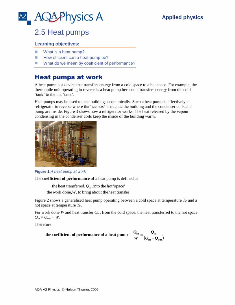
Heat pumps at work
A heat pump is a device that transfers energy from a cold space to a hot space. For example, the
thermopile unit operating in reverse is a heat pump because it transfers energy from the cold
‘tank’ to the hot ‘tank’.
Heat pumps may be used to heat buildings economically. Such a heat pump is effectively a
refrigerator in reverse where the ‘ice box’ is outside the building and the condenser coils and
pump are inside. Figure 3 shows how a refrigerator works. The heat released by the vapour
condensing in the condenser coils keep the inside of the building warm.
Figure 1 A heat pump at work
The coefficient of performance of a heat pump is defined as
ferheat trans about the bring to, done, work the
space''hot theinto , ferred,heat trans the in
W
Q
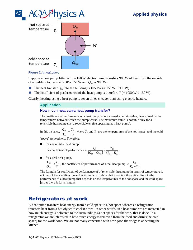
Figure 2 shows a generalised heat pump operating between a cold space at temperature TC and a
hot space at temperature TH.
For work done W and heat transfer Qout from the cold space, the heat transferred to the hot space
Qin = Qout + W.
Therefore
the coefficient of performance of a heat pump = outin
inin
Q
W
Q
AQA A2 Physics © Nelson Thornes 2009
Applied physics
Figure 2 A heat pump
Suppose a heat pump fitted with a 150 W electric pump transfers 900
W of heat from the outside
of a building to the inside. W = 150 W and Qout = 900
W.
The heat transfer Qin into the building is 1050 W (= 150
W + 900
W).
The coefficient of performance of the heat pump is therefore 7 (= 1050 W ÷ 150
W).
Clearly, heating using a heat pump is seven times cheaper than using electric heaters.
Application
How much heat can a heat pump transfer?
The coefficient of performance of a heat pump cannot exceed a certain value, determined by the
temperatures between which the pump works. The maximum value is possible only for a
reversible heat pump (i.e. a reversible engine operating as a heat pump).
In this instance, C
H
out
in
T
T
Q
Q where TH and TC are the temperatures of the hot ‘space’ and the cold
‘space’ respectively. Therefore:
for a reversible heat pump,
the coefficient of performance = CH
H
outin
in
TT
T
Q
for a real heat pump,
C
H
out
in
T
T
Q
Q , the coefficient of performance of a real heat pump
CH
H
TT
T
The formula for coefficient of performance of a ‘reversible’ heat pump in terms of temperature is
not part of the specification and is given here to show that there is a theoretical limit to the
performance of a heat pump that depends on the temperatures of the hot space and the cold space,
just as there is for an engine.
Refrigerators at work
A heat pump transfers heat energy from a cold space to a hot space whereas a refrigerator
transfers heat from a hot object to cool it down. In other words, in a heat pump we are interested in
how much energy is delivered to the surroundings (a hot space) for the work that is done. In a
refrigerator we are interested in how much energy is removed from the food and drink (the cold
space) for the work done. We are not really concerned with how good the fridge is at heating the
kitchen!
AQA A2 Physics © Nelson Thornes 2009
Applied physics
This difference in function between a heat pump and a refrigerator means the coefficient of
performance of a refrigerator is defined as W
Qout (in comparison with W
Qin for a heat pump).
Therefore:
the coefficient of performance of a refrigerator = outin
outout
Q
W
Q
For example, a refrigerator with a coefficient of performance of 5 and fitted with a 20 W electric
pump extracts heat from the cold space at a rate of 100 W (= 5 × 20
W) and transfers 120
W of
heat to the hot space.
Application
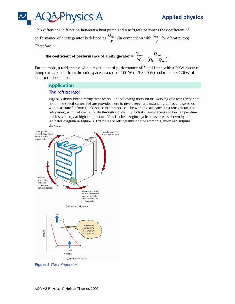
The refrigerator
Figure 3 shows how a refrigerator works. The following notes on the working of a refrigerator are
not on the specification and are provided here to give deeper understanding of basic ideas to do
with heat transfer from a cold space to a hot space. The working substance in a refrigerator, the
refrigerant, is forced continuously through a cycle in which it absorbs energy at low temperature
and loses energy at high temperature. This is a heat engine cycle in reverse, as shown by the
indicator diagram in Figure 3. Examples of refrigerants include ammonia, freon and sulphur
dioxide.
Figure 3 The refrigerator
AQA A2 Physics © Nelson Thornes 2009
Applied physics
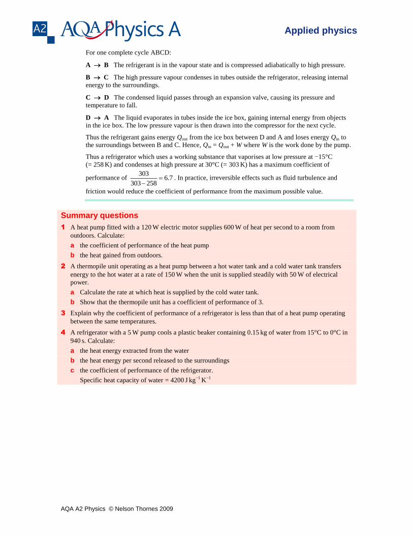
For one complete cycle ABCD:
A B The refrigerant is in the vapour state and is compressed adiabatically to high pressure.
B C The high pressure vapour condenses in tubes outside the refrigerator, releasing internal
energy to the surroundings.
C D The condensed liquid passes through an expansion valve, causing its pressure and
temperature to fall.
D A The liquid evaporates in tubes inside the ice box, gaining internal energy from objects
in the ice box. The low pressure vapour is then drawn into the compressor for the next cycle.
Thus the refrigerant gains energy Qout from the ice box between D and A and loses energy Qin to
the surroundings between B and C. Hence, Qin = Qout + W where W is the work done by the pump.
Thus a refrigerator which uses a working substance that vaporises at low pressure at −15°C
(= 258 K) and condenses at high pressure at 30°C (= 303
K) has a maximum coefficient of
performance of 7.6258303
303
. In practice, irreversible effects such as fluid turbulence and
friction would reduce the coefficient of performance from the maximum possible value.
Summary questions
1 A heat pump fitted with a 120 W electric motor supplies 600
W of heat per second to a room from
outdoors. Calculate:
a the coefficient of performance of the heat pump
b the heat gained from outdoors.
2 A thermopile unit operating as a heat pump between a hot water tank and a cold water tank transfers
energy to the hot water at a rate of 150 W when the unit is supplied steadily with 50
W of electrical
power.
a Calculate the rate at which heat is supplied by the cold water tank.
b Show that the thermopile unit has a coefficient of performance of 3.
3 Explain why the coefficient of performance of a refrigerator is less than that of a heat pump operating
between the same temperatures.
4 A refrigerator with a 5 W pump cools a plastic beaker containing 0.15
kg of water from 15°C to 0°C in
940 s. Calculate:
a the heat energy extracted from the water
b the heat energy per second released to the surroundings
c the coefficient of performance of the refrigerator.
Specific heat capacity of water = 4200 J
kg
−1 K
−1
AQA A2 Physics © Nelson Thornes 2009
Applied physics
Appendices The notes in the two appendices are not required for the specification. They are provided to
enable a deeper understanding of the topics.
Appendix A Heat capacities of an ideal gas
Heat transfer, Q, to a gas to change its temperature must increase its internal energy. But if the
gas expands when it is heated, it uses energy to do work. So the heat transfer Q to the gas is equal
to its increase of internal energy + the work done by the gas to expand.
Q = U + pV
where
V = change of volume at constant pressure p
Q = heat transfer to the gas
U = change of its internal energy.
The molar heat capacity at constant volume, CV, is defined as the heat transfer required to raise
the temperature of 1 mole by 1 K at constant volume.
For 1 mole of gas heated at constant volume so its temperature increases by T, the heat transfer
Q = CVT.
Since V = 0, then no work is done hence the increase of internal energy U = Q = CVT.
The molar heat capacity at constant pressure, CP, is defined as the heat transfer to the gas
required to raise the temperature of 1 mole by 1 K at constant pressure.
For 1 mole of gas heated at constant pressure so its temperature increases by T, the heat transfer
Q = CPT.
The internal energy increases by the same amount as at constant volume because the temperature
increase is the same. So U = CVT. However, the gas expands to keep the pressure constant. So
it does work equal to pV where V is the increase of volume.
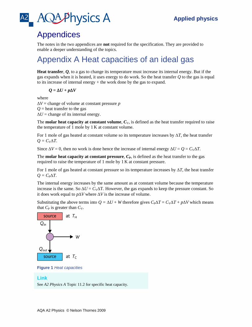
Substituting the above terms into Q = U + W therefore gives CPT = CVT + pV which means
that CP is greater than CV.
Figure 1 Heat capacities
Link
See A2 Physics A Topic 11.2 for specific heat capacity.
AQA A2 Physics © Nelson Thornes 2009
Applied physics
The adiabatic constant, , of a gas is defined as the ratio of its molar specific heats V
P
C
C
It can be shown that:
for a monatomic gas, = 3
5 = 1.67
for a diatomic gas (i.e. two atoms per molecule), = 5
7 = 1.40
for a polyatomic gas (i.e. more than two atoms per molecule), = 3
4 = 1.33
More about the adiabatic constant
The notes below are not required for the specification and are intended to give a deeper
understanding of the thermodynamics of an ideal gas.
For 1 mole of an ideal gas heated by a temperature increase T at constant pressure p, as
explained above, CPT = CVT + pV
Before heating the gas, its pressure, volume and temperature are such that pV = RT
After heating the gas, its pressure, volume and temperature are such that
p(V + V) = R(T + T)
Hence, by subtraction, pV = RT
Hence CPT = CV T + pV = CV T + RT
Cancelling T and rearranging therefore gives:
Cp − CV = R
The internal energy U of an ideal gas is due entirely to the kinetic energy of its molecules.
Using the kinetic theory equation pV = 31 Nmcrms
2, we can show that the total kinetic energy of
1 mole of its molecules at temperature T is 23 RT. Hence its internal energy U =
23 RT at
temperature T.
If the gas is monatomic and its temperature rises by 1 K, its internal energy rises by
23 R.
Because no work is done by the gas, this increase in internal energy is equal to the heat
transfer at constant volume, CVT. In other words CVT = 23 R.
Also, since CP − CV = R, CP = CV + R = 25 R.
Therefore, for a monatomic gas, = V
P
C
C =
R
R
23
25
= 3
5 = 1.67.
Each molecule of a monatomic gas can move in three independent ‘translational’ directions
so it is said to have three ‘degrees of freedom. We can associate a third of the internal energy
of the gas molecules with each degree of freedom. A diatomic gas has two further degrees of
freedom due to it having two independent directions of rotation perpendicular to its
‘diatomic’ axis.
AQA A2 Physics © Nelson Thornes 2009
Applied physics
The internal energy of 1 mole of a diatomic gas at temperature T is therefore 25 RT.
Hence CVT = 25 RT and CPT =
27 RT. Therefore =
V
P
C
C =
5
7 = 1.40
Each molecule of a polyatomic gas has six degrees of freedom, three as for a monatomic gas
and three due to it having three independent directions of rotation.
The internal energy of 1 mole of such a gas at temperature T is therefore 26 RT.
Hence CVT = 26 RT and CPT =
28 RT. Therefore =
V
P
C
C =
6
8 = 1.33
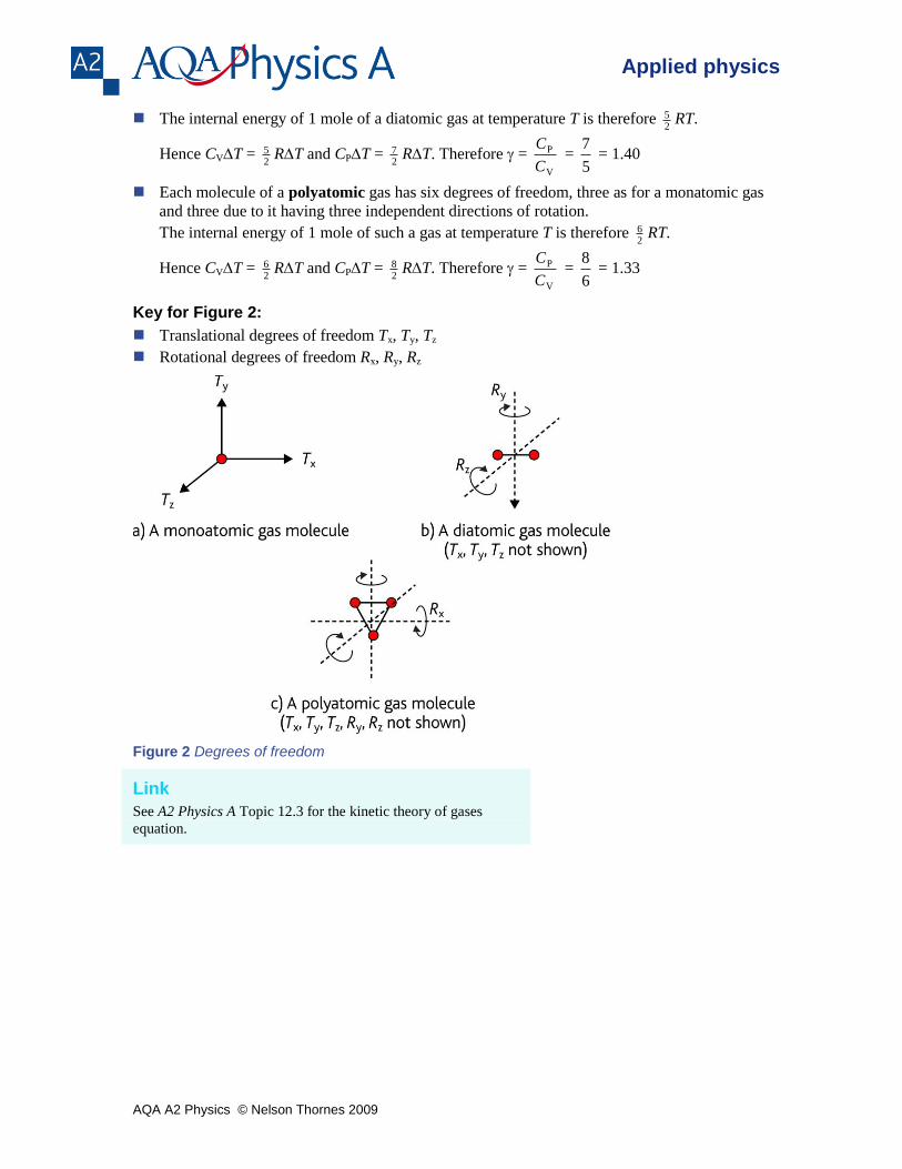
Key for Figure 2:
Translational degrees of freedom Tx, Ty, Tz
Rotational degrees of freedom Rx, Ry, Rz
Figure 2 Degrees of freedom
Link
See A2 Physics A Topic 12.3 for the kinetic theory of gases
equation.
AQA A2 Physics © Nelson Thornes 2009
Applied physics
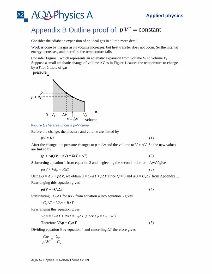
Appendix B Outline proof of constant γ Vp
Consider the adiabatic expansion of an ideal gas in a little more detail.
Work is done by the gas as its volume increases, but heat transfer does not occur. So the internal
energy decreases, and therefore the temperature falls.
Consider Figure 1 which represents an adiabatic expansion from volume V1 to volume V2
Suppose a small adiabatic change of volume V as in Figure 1 causes the temperature to change
by T for 1 mole of gas.
Figure 1 The area under a p–V curve
Before the change, the pressure and volume are linked by
pV = RT (1)
After the change, the pressure changes to p + p and the volume to V + V. So the new values
are linked by
(p + p)(V + V) = R(T + T) (2)
Subtracting equation 1 from equation 2 and neglecting the second order term pV gives
pV + Vp = RT (3)
Using Q = U + pV, we obtain 0 = CVT + pV since Q = 0 and U = CVT from Appendix 1.
Rearranging this equation gives
pV = −CVT (4)
Substituting −CVT for pV from equation 4 into equation 3 gives
−CVT + Vp = RT
Rearranging this equation gives
Vp = CVT + RT = CPT (since CP = CV + R )
Therefore Vp = CPT (5)
Dividing equation 5 by equation 4 and cancelling T therefore gives
V
P
C
C
Vp
pV
AQA A2 Physics © Nelson Thornes 2009
Applied physics
Rearranging this equation and substituting for V
P
C
C therefore gives
V
p
V
p
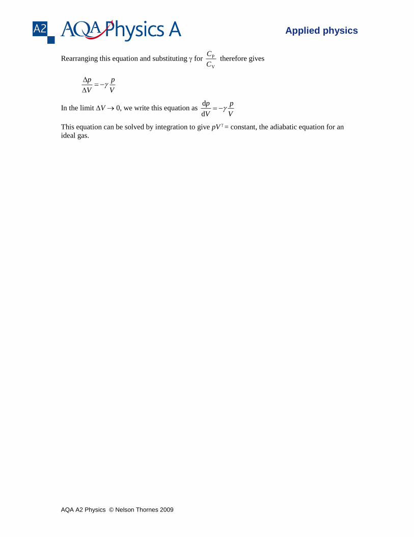
In the limit V 0, we write this equation as V
p
V
p
d
d
This equation can be solved by integration to give pV
= constant, the adiabatic equation for an
ideal gas.
AQA A2 Physics © Nelson Thornes 2009
Applied physics
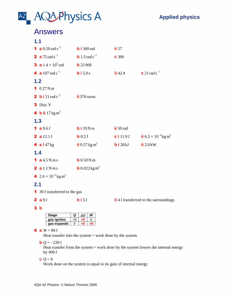
Answers
1.1
1 a 0.20 rad
s
−2 b i 360
rad ii 57
2 a 75 rad
s
−1 b 1.5
rad
s
−2 c 300
3 a 1.4 × 10⁵ rad b 22
000
4 a 107 rad
s
−1 b i 5.0
s ii 42.4 c 21
rad
s
−1
1.2
1 0.27 N
m
2 b i 21 rad
s
−2 ii
376 turns
3 Disc Y
4 b ii 17 kg
m
2
1.3
1 a 9.6 J b i 19
N
m ii 50
rad
2 a 12.1 J b 0.2
J c i 11.9
J ii 6.3 × 10
−4 kg
m
2
4 a i 47 kg ii 0.57
kg
m
2 b i 28
kJ ii 2.0
kW
1.4
1 a 4.5 N
m
s b 0.50
N
m
2 a 1.1 N
m
s b 0.022
kg
m
2
4 2.6 × 10⁻²
kg m
2
2.1
1 30 J transferred to the gas
2 a 9 J b i 5
J ii 4 J transferred to the surroundings
3 b
4 a W = 80 J
Heat transfer into the system = work done by the system
b Q = −220 J
Heat transfer from the system + work done by the system lowers the internal energy
by 400 J
c Q = 0
Work done on the system is equal to its gain of internal energy
Stage Q U W
gas ignites >0 >0 0
gas expands 0 <0 >0
AQA A2 Physics © Nelson Thornes 2009
Applied physics
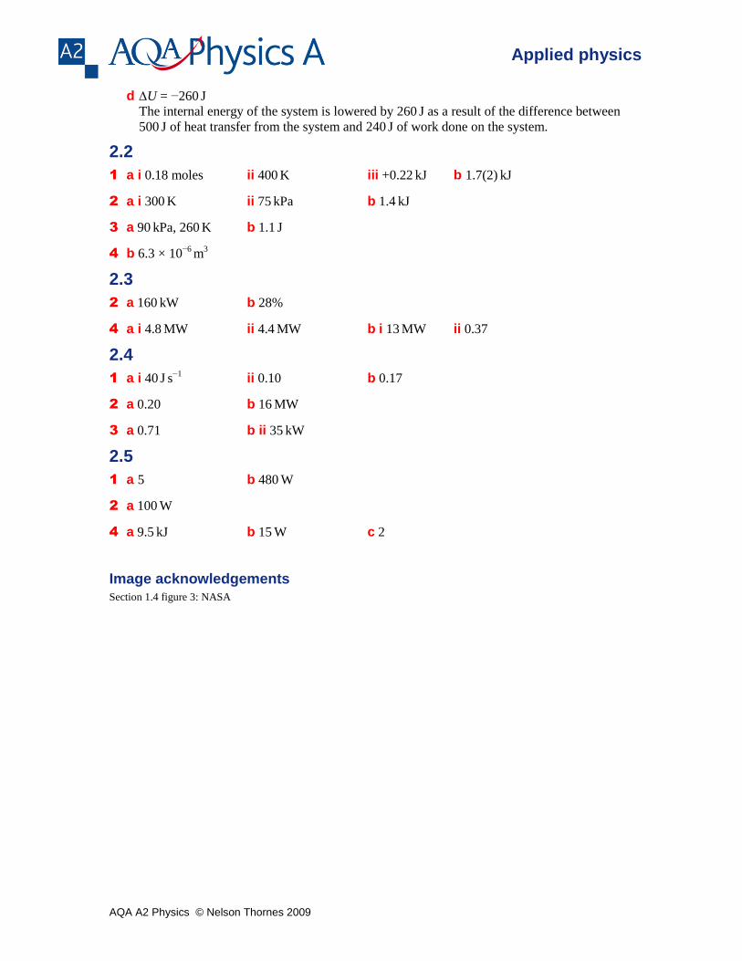
d U = −260 J
The internal energy of the system is lowered by 260 J as a result of the difference between
500 J of heat transfer from the system and 240
J of work done on the system.
2.2
1 a i 0.18 moles ii 400 K iii +0.22
kJ b 1.7(2)
kJ
2 a i 300 K ii 75
kPa b 1.4
kJ
3 a 90 kPa, 260
K b 1.1
J
4 b 6.3 × 10⁻⁶
m3
2.3
2 a 160 kW b 28%
4 a i 4.8 MW ii 4.4
MW b i 13
MW ii 0.37
2.4
1 a i 40 J
s
−1 ii 0.10 b 0.17
2 a 0.20 b 16 MW
3 a 0.71 b ii 35 kW
2.5
1 a 5 b 480 W
2 a 100 W
4 a 9.5 kJ b 15
W c 2
Image acknowledgements Section 1.4 figure 3: NASA