chapter 3 digital transmission - york university · chapter 3 digital transmission ... unipolar....
TRANSCRIPT
Chapter 3 Digital Transmission
FundamentalsLine Coding
Modems and Digital Modulation
Digital transmission of Digital Signals

Digital transmission of Digital Signals
• data levels – number of values / levels used to represent data(typically only two: 0 & 1)
• signal levels – number of values / levels allowed in a particular signal
Data Level vs. Signal Level
DC
Two signal levels, two data levels.
Three signal levels, two data levels.

Chapter 3Digital Transmission
FundamentalsLine Coding
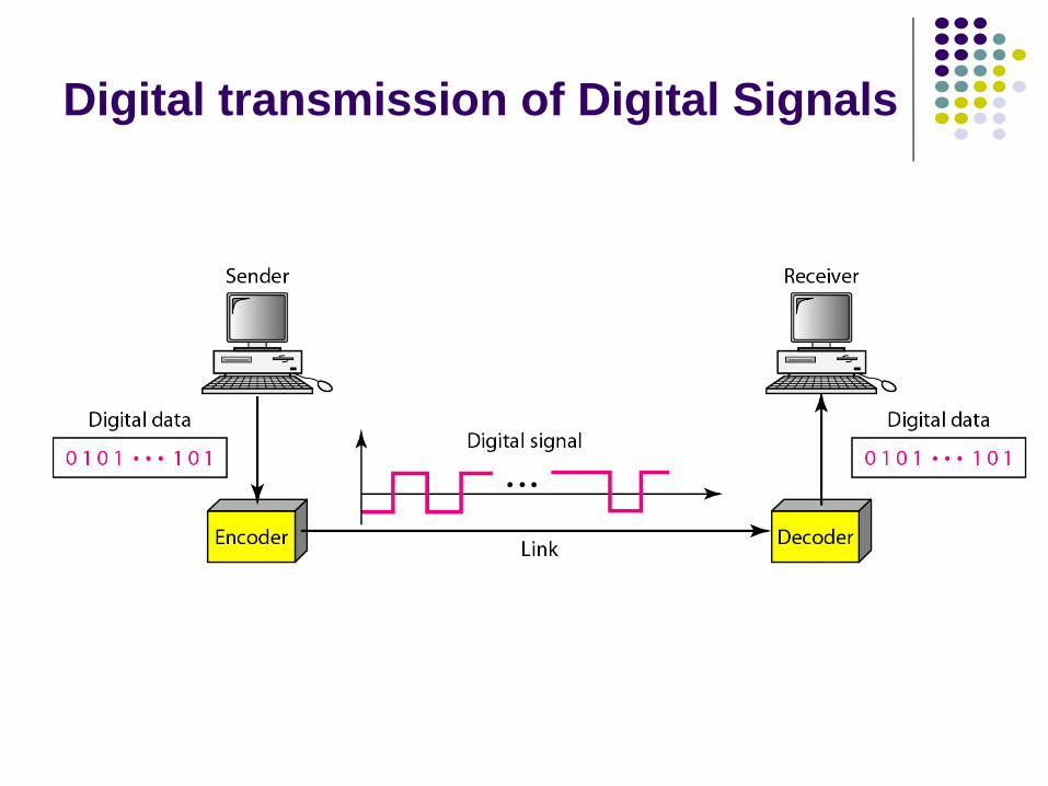
What is Line Coding?Mapping of binary information sequence into the digital signal that enters the channelprocess of converting binary data (sequence of bits) to a digital signaldigital signal depends ‘linearly’ on information bits, i.e. bits are transmitted ‘one-by-one’ – different from block coding
Ex. “1” maps to +A square pulse; “0” to –A pulse

Line Coding: Design Consideration
– some line coding schemes have a residual (DC) component, generally undesirabletransformers do not allow passage of DC componentDC component ⇒ extra energy – useless!
DC Component in Line Coding
56 kbps ⇒0.0178 ms
Self-Synchronization (Clocking)– to correctly interpret signal received from sender, receiver’s bit interval mustcorrespond exactly to sender’s bit intervals
• if receiver clock is faster/slower, bit intervals are not matched ⇒ receiver mightmisinterpret signal
• self-synchronizing digital signals include timing information in itself, to indicate the beginning and end of each pulse
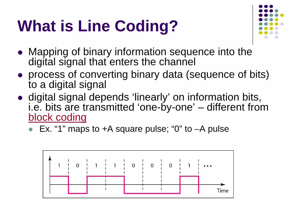
uses only one non-zero voltage level (0 and +)
uses three voltage level (+, 0, -)
Line Coding Schemes

Line coding examples
NRZ-inverted(differentialencoding)
1 0 1 0 1 1 0 01
UnipolarNRZ
Bipolarencoding
Manchesterencoding
DifferentialManchester
encoding
Polar NRZ

9
Unipolar Line Coding – uses only one non-zero and one zero voltagelevel
• (e.g.) 0 = zero level, 1 = non-zero level
• simple to implement, but obsolete due to two mainproblems:
DC component present lack of synchronization for long series of 1-s or 0-s
Unipolar Code

Polar Line Coding – uses two non-zero voltage level for representationof two data levels – one positive and one negative• “DC-problem” alleviated ☺
• 4 main types of polar coding:
NRZ-level NRZ-invert
(1) Nonreturn to Zero (NRZ) • NRZ-level: signal level represents particular bit,(e.g.) 0 = positive volt. , 1 = negative volt.
lack of synchronization for long series of 1-s & 0-s
• NRZ-invert: inversion of voltage level represents bit 1,no voltage change represents bit 0
1s in data streams enable synchronizationlong sequence of 0-s still a problem
Polar Coding

11
NRZ-I is better than NRZ-L, but it still does not provide complete synchronization.To ensure complete synchronization, there must be a signal change for each bit.
Data is represented by
signal level.
Logical ‘1’ is represented by
change in signal level.
problem with long sequencesof 0-s and 1-s
problem with long sequencesof 0-s
Polar Coding (NRZ)
12
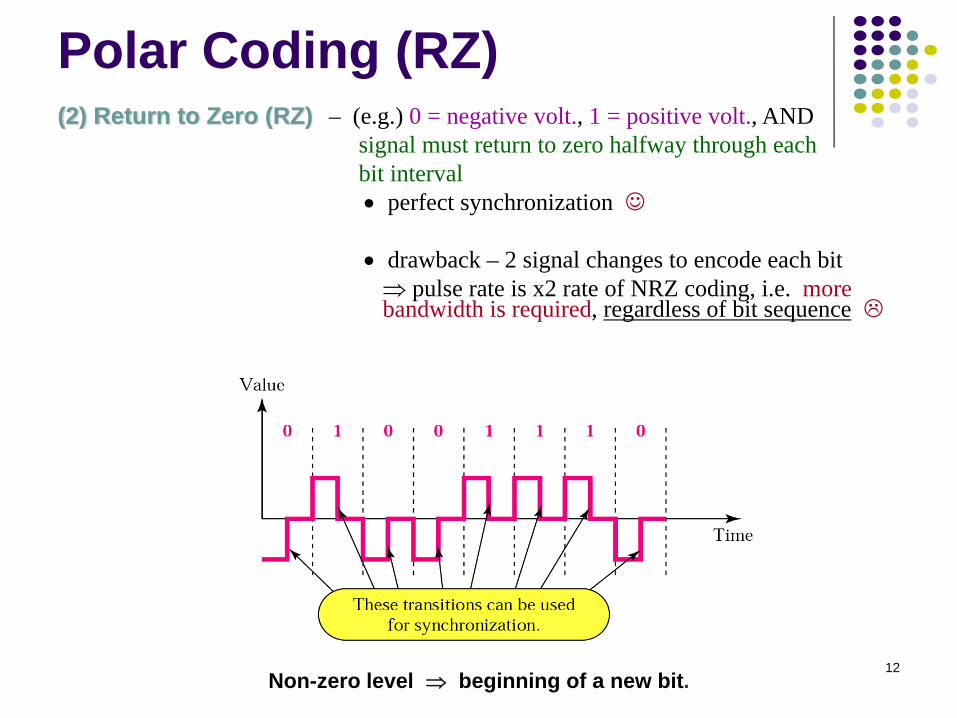
(2) Return to Zero (RZ) – (e.g.) 0 = negative volt., 1 = positive volt., ANDsignal must return to zero halfway through eachbit interval• perfect synchronization ☺
• drawback – 2 signal changes to encode each bit⇒ pulse rate is x2 rate of NRZ coding, i.e. more bandwidth is required, regardless of bit sequence
Non-zero level ⇒ beginning of a new bit.
Polar Coding (RZ)

13
(3) Manchester – inversion at the middle of each bit interval is used for both synchronization and bit representation
• 0 = pos-to-neg transition, 1 = neg-to-pos transition• perfect synchronization ☺
• there is always transition at the middle of the bit, and maybeone transition at the end of each bit
• fine for alternating sequences of bits (10101), but wastesbandwidth for long runs of 1-s or 0-s
• used by IEEE 802.3 (Ethernet)
Manchester code

14
(4) Differential Manchester – inversion in the middle of bit interval is usedfor synchronization – presence or absenceof additional transition at the beginning ofnext bit interval identifies the bit
• 0 = transition, 1 = no transition• perfect synchronization ☺
• fine for long runs of 1s, but wastes bandwidthfor long runs of 0-s
• used by IEEE 802.5 (Token Ring)
Differential Manchester code

15
Bipolar Line Coding – uses two non-zero and zero voltage level for representation of two data levels
• 0 = zero level; 1 = alternating pos and neg level
• e.g. if 1st ‘bit 1’ is represented by positive amplitude,the 2nd will be represented by negative amplitude,the 3rd by positive, etc.
• less bandwidth required than with Manchester coding (for any sequence of bits) ☺
• loss of synchronization is possible for long runs of 0-s
Bipolar Code
16
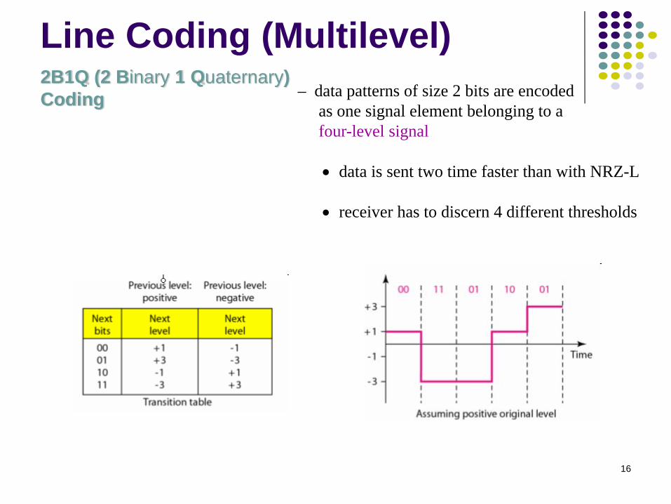
2B1Q (2 Binary 1 Quaternary)Coding – data patterns of size 2 bits are encoded
as one signal element belonging to a four-level signal
• data is sent two time faster than with NRZ-L
• receiver has to discern 4 different thresholds
Line Coding (Multilevel)

17
Data Rate – number of data elements (bits) sent in 1 sec – unit: bps
Signal Rate – number of signal elements (pulses) sent in 1 sec – unit: baud
One goal of data communications is to increase data rate (speed of transmission)while decreasing signal rate (bandwidth requirements).
Data Rate vs. Baud Rate
18
Exercise
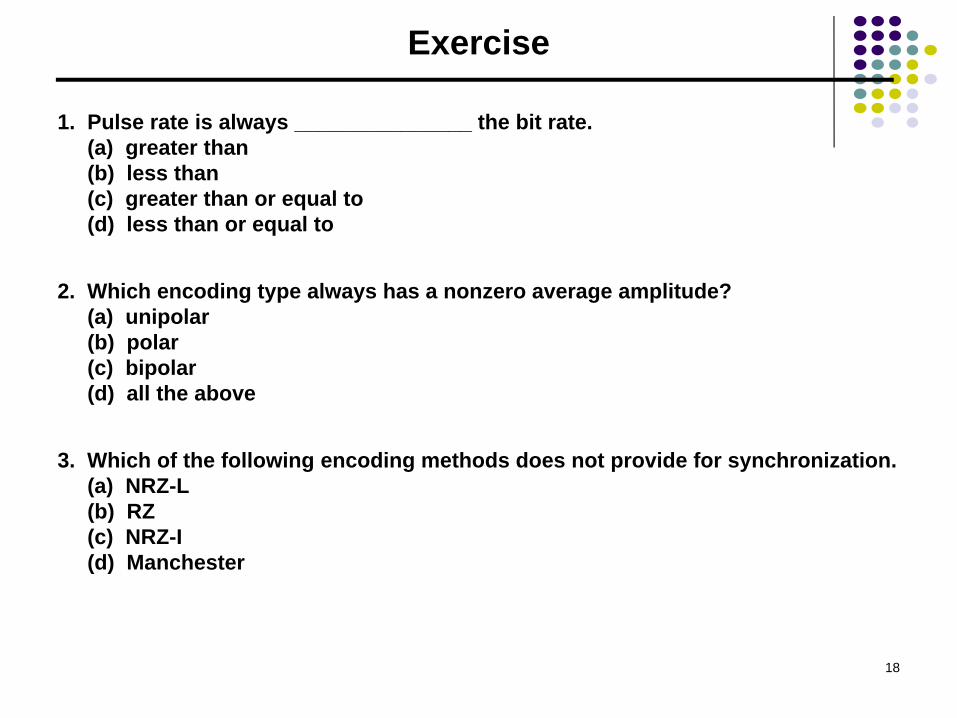
1. Pulse rate is always _______________ the bit rate.(a) greater than(b) less than(c) greater than or equal to(d) less than or equal to
2. Which encoding type always has a nonzero average amplitude?(a) unipolar(b) polar(c) bipolar(d) all the above
3. Which of the following encoding methods does not provide for synchronization.(a) NRZ-L(b) RZ(c) NRZ-I(d) Manchester