chapter 3 tcp/ip - georgia southern university-armstrong...
TRANSCRIPT

Chapter 3
TCP/IP

2
Objectives
• Discuss the origins of TCP/IP
• Identify and discuss the different layer functions of TCP/IP
• Describe the functions performed by protocols in the TCP/IP protocol suite, including ICMP, UDP, TCP, ARP, and RARP

3
Objectives (continued)
• Use Ping and Trace and describe their functions
• Explain how packets are transmitted
• Describe the Cisco three-layer hierarchical model

4
Origins of TCP/IP• Transmission Control Protocol/Internet Protocol (TCP/IP)
– Resulted from a coordinated effort by the U.S. Department of Defense
(DOD)
• Advanced Research Projects Agency (ARPA)
– Charged with creating a wide area network (WAN)
– Results were TCP/IP and ARPANET
• DOD funded two projects
– The adaptation of TCP/IP to work with UNIX
– The inclusion of the TCP/IP protocol with Berkeley UNIX (BSD UNIX)

5
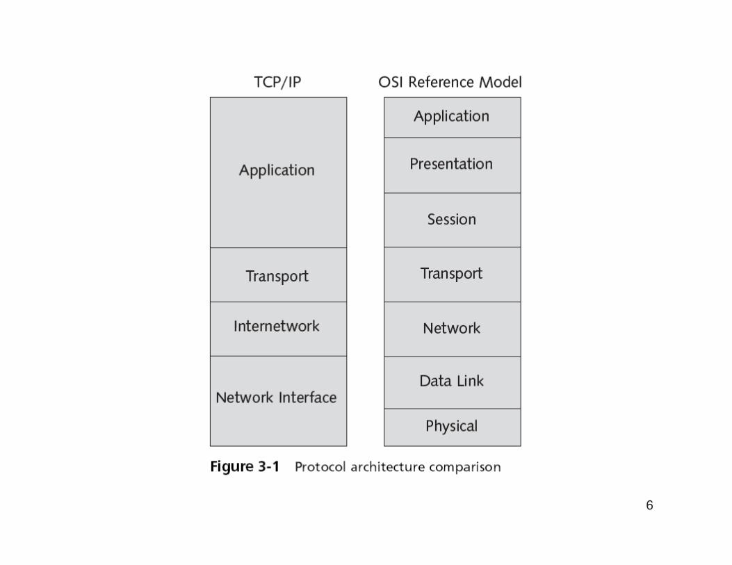
Overview of the TCP/IP Protocol Suite
• The TCP/IP model explains how the protocol suite works to provide communications
– Four layers: Application, Transport, Internetwork, and
Network Interface
• Requests for Comments (RFCs)
– Define, describe, and standardize the implementation
and configuration of the TCP/IP protocol suite
6

7
Application Layer
• Protocols at the TCP/IP Application layer include:
– File Transfer Protocol (FTP)
– Trivial File Transfer Protocol (TFTP)
– Network File System (NFS)
– Simple Mail Transfer Protocol (SMTP)
– Terminal emulation protocol (telnet)
– Remote login application (rlogin)
– Simple Network Management Protocol (SNMP)
– Domain Name System (DNS)
– Hypertext Transfer Protocol (HTTP)

8
Transport Layer
• Performs end-to-end packet delivery, reliability, and flow control
• Protocols:
– TCP provides reliable, connection-oriented
communications between two hosts
• Requires more network overhead
– UDP provides connectionless datagram services
between two hosts
• Faster but less reliable
• Reliability is left to the Application layer

9
Transport Layer (continued)• Ports
– TCP and UDP use port numbers for communications between hosts
– Port numbers are divided into three ranges:
• Well Known Ports are those from 1 through 1,023
• Registered Ports are those from 1,024 through 49,151
• Dynamic/Private Ports are those from 49,152 through 65,535

10

11
Transport Layer (continued)
• TCP three-way handshake
– Establishes a reliable connection between two points
– TCP transmits three packets before the actual data transfer occurs
– Before two computers can communicate over TCP, they must
synchronize their initial sequence numbers (ISN)
– A reset packet (RST) indicates that a TCP connection is to be
terminated without further interaction

12

13

14

15
Transport Layer (continued)
• TCP sliding windows
– Control the flow and efficiency of communication
– Also known as windowing
• A method of controlling packet flow between hosts
• Allows multiple packets to be sent and affirmed with a single acknowledgment packet
– The size of the TCP window determines the number of acknowledgments sent for a given data transfer
– Networks that perform large data transfers should use large window sizes

16
Transport Layer (continued)
• TCP sliding windows (continued)
– Other flow control methods include
• Buffering
• Congestion avoidance

17
Internetwork Layer
• Four main protocols function at this layer
– Internet Protocol (IP)
– Internet Control Message Protocol (ICMP)
– Address Resolution Protocol (ARP)
– Reverse Address Resolution Protocol (RARP)
• ARP
– A routed protocol
– Maps IP addresses to MAC addresses
– ARP tables contain the MAC and IP addresses of other devices on the network

Internetwork Layer
18

19
Internetwork Layer (continued)• ARP (continued)
– When a computer transmits a frame to a destination on the local
network
• It checks the ARP cache for an IP to MAC address mapping for the
destination node
• ARP request
– If a source computer cannot locate an IP to MAC address mapping in its
ARP table
• It must obtain the correct mapping

20
Internetwork Layer (continued)
21
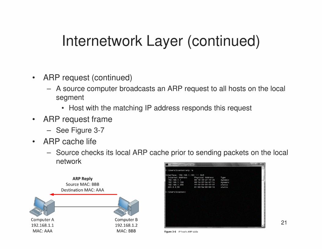
Internetwork Layer (continued)
• ARP request (continued)
– A source computer broadcasts an ARP request to all hosts on the local
segment
• Host with the matching IP address responds this request
• ARP request frame
– See Figure 3-7
• ARP cache life
– Source checks its local ARP cache prior to sending packets on the local
network

22
Internetwork Layer (continued)

23
Internetwork Layer (continued)
• ARP cache life (continued)
– Important that the mappings are correct
– Network devices place a timer on ARP entries
– ARP tables reduce network traffic
• Reverse Address Resolution Protocol (RARP)
– Similar to ARP
– Used primarily by diskless workstations
• Which have MAC addresses burned into their network cards but no IP addresses
– Client’s IP configuration is stored on a RARP server

24
Internetwork Layer (continued)
• RARP request frame
– See Figure 3-8
• RARP client
– Once a RARP client receives a RARP reply, it configures its IP networking components
• By copying its IP address configuration information into its local RAM
• ARP and RARP compared
– ARP is concerned with obtaining the MAC address of other clients
– RARP obtains the IP address of the local host

25

26
Internetwork Layer (continued)
• ARP and RARP compared (continued)
– The local host maintains the ARP table
– A RARP server maintains the RARP table
– The local host uses an ARP reply to update its ARP
table and to send frames to the destination
– The RARP reply is used to configure the IP protocol
on the local host
• Routers and ARP
– ARP requests use broadcasts
– Routers filter broadcast traffic
– Source must forward the frame to the router

27
Internetwork Layer (continued)
• ARP tables
– Routers maintain ARP tables to assist in transmitting
frames from one network to another
– A router uses ARP just as other hosts use ARP
– Routers have multiple network interfaces and
therefore also include the port numbers of their NICs
in the ARP table
• The Ping utility
– Packet Internet Groper (Ping) utility verifies
connectivity between two points
– Uses ICMP echo request/reply messages

28
Internetwork Layer (continued)

29
Internetwork Layer (continued)

30
Internetwork Layer (continued)
• The Trace utility
– Uses ICMP echo request/reply messages
– Can verify Internetwork layer (OSI-Network layer)
connectivity
– Shows the exact path a packet takes from the
source to the destination
• Accomplished through the use of the time-to-live
(TTL) counter
– Several different malicious network attacks have
also been created using ICMP messages
• Example: ICMP flood

31
Internetwork Layer (continued)

32
Network Interface Layer
• Plays the same role as the Data Link and Physical layers of the OSI model
• The MAC address, network card drivers, and specific interfaces for the network card function at this level
• No specific IP functions exist at this layer
– Because the layer’s focus is on communication with
the network card and other networking hardware

33
Understanding Frame Transmission
• Each host on a segment evaluates the frame
– To determine whether the listed destination MAC
address matches its own or is a broadcast to all hosts
• The host makes a copy of the frame and sends the original along the network path
• On the destination host, frames are sent up the TCP/IP stack
– Removing each layer header information
• For a packet to be routed on a TCP/IP internetwork
– An IP address and MAC address are required for both
the source and destination hosts
34
Routers on the Network
• A router requires:
– An IP address for every network segment to which it is
connected
– A separate network interface or port for each network
segment
• Computers send frames to destinations that are not on their segment to the router (default gateway)
• The router must determine which subnet should receive the frame
– The router references its routing table

35
Routers on the Network (continued)

36
Network to Network
• Routers maintain routing tables that they use to route packets from one network to another
• When a network uses TCP/IP, each port on a router requires an IP address
– Allows the router to correctly forward the packet to the
appropriate network segment
• On a TCP/IP network, the logical addresses on a certain segment must be matched
– If you move a computer from one segment to another,
the IP address will have to be changed

37
Network to Network (continued)
38
Dynamic or Static Tables
• Routing tables match network addresses with the addresses of the routers that handle those networks
– The tables can be built statically or dynamically
• Dynamic updates are provided through routing protocols
– A router capable of dynamic routing can choose from
among the various routes on a network
– The router communicates with other dynamic routers
• To determine the most efficient route from one point to
another on the network
39
Dynamic or Static Tables (continued)
• Methods to determine the best path across a network
– The distance-vector algorithm
– The link-state algorithm

40
Transmitting Packets to Remote
Segments
• When TCP/IP hosts transmit packets to remote segments
– They contact their default gateway (usually a router)
• The router checks its routing tables against the destination IP address
– To locate the appropriate network interface through
which to forward the packet
• Router re-addresses the frame or sends the packet to the next router in the path (indirect routing)

41
Routing Packets

42
Routing Packets (continued)

43
Routing Packets (continued)
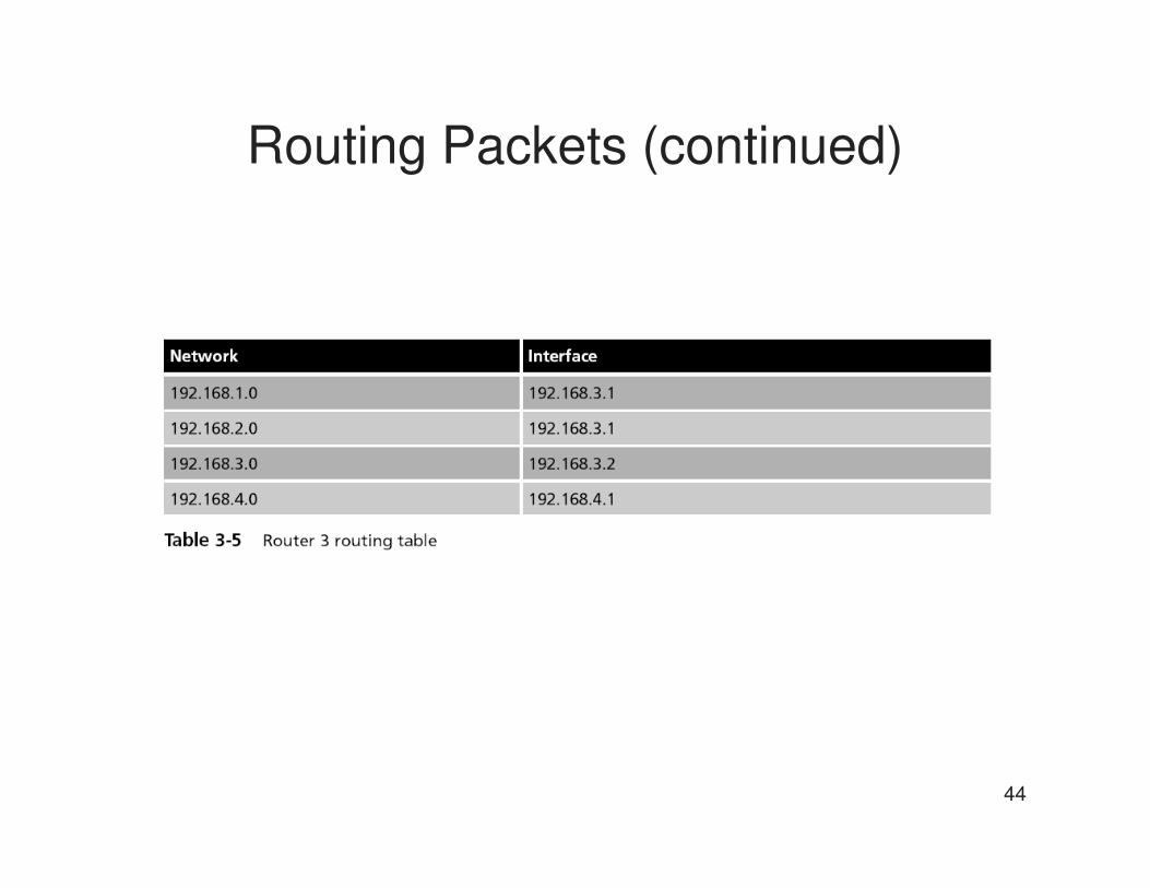
44
Routing Packets (continued)

45
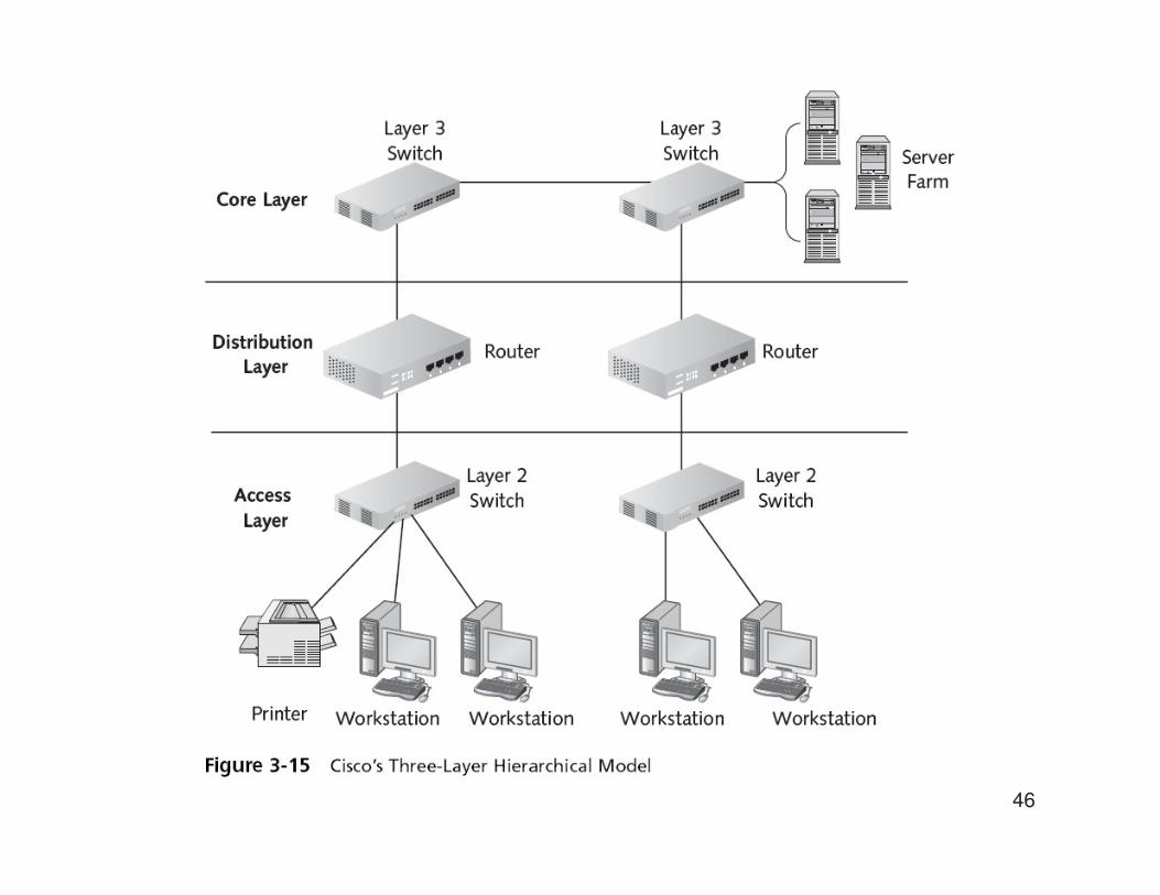
The Cisco Three-Layer Hierarchical
Model
• Cisco Three-Layer Hierarchical model
– Does not describe how communications take place
– Focuses on how best to design a network
• Especially a relatively large network or one that is
expected to grow
• Each layer of the model is involved in specific functions
– Is typically defined by a particular type of device
• The three layers of the model from bottom up are Access, Distribution, and Core
46