chapter 4 1 transport network aspects - dspcsp · lte backhaul is mostly based on gbe interfaces...
TRANSCRIPT

Chapter 4 Transport Network Aspects 1
Yaakov (J) Stein Yuri Gittik Ron Insler
RAD Data Communications, Ltd (Tel Aviv)
In this chapter we discuss various transport network technologies used for backhaul (i.e. connection the NG-RAN to the 5GC), fronthaul (i.e. connecting NG-RAN to RRG) and midhaul (connecting network nodes in split NG-RAN architecture). This is illustrated in Figure 4.1 below.
Figure 4.1: Backhaul, midhaul, and fronthaul (xHaul) transport networks
The figure above showing an xHaul as a straight line connecting network nodes, is a bit misleading as in practice an xHaul can have a complex network topology and many links, using many different technologies. This aspect is often overlooked in technical specifications (e.g. in 3GPP) and architecture documents. In the present section we discuss this in more detail.
4.1 Key ideas
The transition from 4G to 5G will strongly impact the transport network, due to requirements for higher data-rates, lower latency, enhanced reliability, energy efficiency, and heightened dynamicity.
Choice of 5G RAN segment defined by functional split (fronthaul through midhaul to backhaul) and RAN planning factors (density, distances, placement of Points of Presence (PoPs), etc.) deeply influence the requirements for transport.
In addition, delivery of disparate services (eMBB, URLLC, and mMTC) requires different transport attributes.
Distributed edge computing, whether for enabling vRAN/cRAN operation, serving the disaggregated transport network, or hosting end-user applications, drives yet more sophisticated transport network designs with compute resources and connectivity of distributed physical and virtual components
1 In 5G RAN architecture, Sasha Sirotkin (ed.), John Wiley and Sons, to be published 2020.
Integration of transport and computational components will produce a new xHaul infrastructure.
To target higher data-rates, new fiber Ethernet technologies (e.g., N*10G, 25G, and higher rates) will supplant the GbE links prevalent for 4G, although some PON solutions may only be sufficient for the near term.
To tackle lower latency, new Time Sensitive Networking (TSN) and Deterministic Networking (DetNet) technologies are being introduced.
New protection switching, fast reroute, self-healing, loop-free alternatives, and frame replication technologies may be employed to address reliability challenges.
Coexistence of traffic with wildly diverging requirements mandates support for network slicing across the transport network.
Backhaul networks for 5G may be based on WDM, OTN, PON, Carrier Ethernet, MPLS, pure IP, segment routing (either MPLS or IPv6 variety), and vertical/horizontal combinations of these; and may be managed using distributed control protocols or centralized management (e.g., SDN).
Introduction of 5G into existing (brownfield) transport networks, will necessitate migration strategies.
All of the above will transform transport networks, whether owned by the mobile operator or by a wholesale provider of backhaul/xHaul services; in most cases the services will be terminated by an enhanced Cell Site Gateway.
The increased number of cells and the stricter time accuracy requirements will necessitate innovative timing solutions.
Network dynamicity and slicing requires tighter interworking between network management systems (and/or SDN controllers) of transport networks and mobile networks.
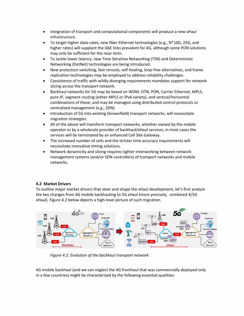
4.2 Market Drivers To outline major market drivers that steer and shape the xHaul development, let’s first analyze the key changes from 4G mobile backhauling to 5G xHaul (more precisely, combined 4/5G xHaul). Figure 4.2 below depicts a high-level picture of such migration.
Figure 4.2: Evolution of the backhaul transport network
4G mobile backhaul (and we can neglect the 4G fronthaul that was commercially deployed only in a few countries) might be characterized by the following essential qualities:

On the whole, connecting radio sites to centralized locations that host content and applications. The exceptional case of MEC that was introduced to bring content closer to users (for example, with local CDN) was not in particular successful, as it was not organic to the 4G standard architecture and required complementary vendor-specific components.
Single Class-of-Services for all applications
Static pre-provisioned connections (“pipes”) with star or ring topology; typically, not direct X2 connections between eNBs, but via an aggregation node
Semi-static network management. 5G xHaul dramatically changes these basic features and entails new ones:
Connectivity to highly distributed content and applications that require various transport attributes:
RAN related – CPR/eCPRI delay/PDV, HARQ delay, split data-rates
Application related – eMBB, URLLC, mMTC: more specifically per application– higher data-rates, lower latency, lower PLR and higher reliability.
By definition multiple Classes-of-Service assured by end-to-end service and network slicing
Orchestrated dynamic connectivity for on-demand mesh topology embracing multiple physical and virtual components
Zero Touch Provisioning (ZTP) and Automation for dynamic end-to-end slicing support.
Such substantial changes furnish major challenges (both engineering and economical) for a mobile operator to define a smooth migration path. In most cases the existing 4G backhaul and aggregation networks will be incrementally enhanced and upgraded to reach the 5G xHaul end-game. Recent practices indicate that such migration will usually be executed in phases; an example scenario consisting of the following phases:
Phase 1: upgrading to support higher data rates
Phase 2: integrating the transport network with edge computing (i.e., MEC)
Phase 3: decreasing latency and increasing reliability
Phase 4: adding support for slicing (different traffic types over a single network infrastructure)
Phase 5: assuring higher density of UEs for IoT (optionally integrated with 4G IoT deployment)
4.3 Defining the problem
At the highest level of abstraction a 5G network consists of three entities: • 5G user equipment (UE) • 5G Radio Access Network (RAN) incorporating the gNB basestation and other elements
to be described later • 5G core network (5GC)
In many cases there is also a catch-all fourth entity - external data networks or server platforms.
5G communications are carried out by interconnecting these entities. 3GPP documents [3GPP 38.401] specify that the RAN consists of a Radio Network Layer (RNL) and a Transport Network Layer (TNL), where the TNL provides services for transport of both user plane and signaling.
3GPP specifications deal in minute detail with all aspects of RNL connectivity between the UE and gNB, but severely under-specify2 the TNL connection between the gNB and the 5GC, viewing connections from the cell site to the core as ideal transport pipes.
The connection between the 5GC and external networks or servers generally utilizes the Internet Protocol (IP) suite, which is defined by documents produced by the Internet Engineering Task Force (IETF). It may additionally entail Ethernet protocols, defined by the IEEE and other organizations.
The connection between the gNBs and the core is called the NG interface. The gNBs can also be interconnected by interfaces named Xn. Transport of data over either the Xn or NG interface is conventionally known as backhaul, in line with the terminology of previous generations of mobile communications.
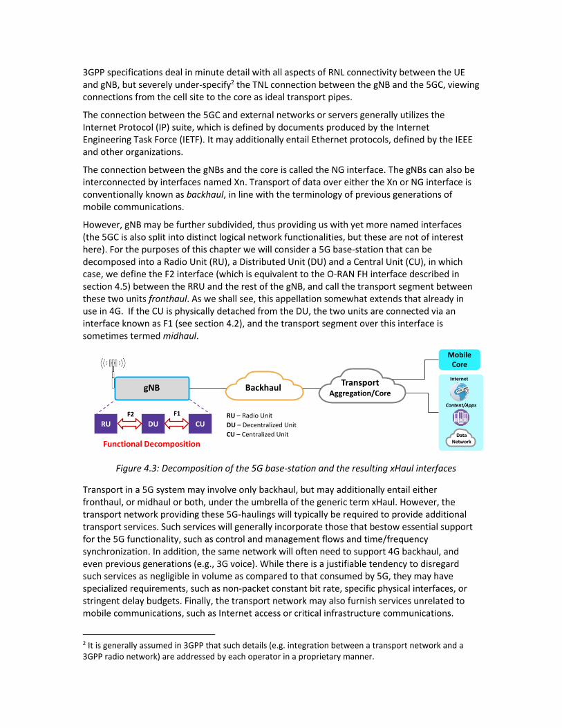
However, gNB may be further subdivided, thus providing us with yet more named interfaces (the 5GC is also split into distinct logical network functionalities, but these are not of interest here). For the purposes of this chapter we will consider a 5G base-station that can be decomposed into a Radio Unit (RU), a Distributed Unit (DU) and a Central Unit (CU), in which case, we define the F2 interface (which is equivalent to the O-RAN FH interface described in section 4.5) between the RRU and the rest of the gNB, and call the transport segment between these two units fronthaul. As we shall see, this appellation somewhat extends that already in use in 4G. If the CU is physically detached from the DU, the two units are connected via an interface known as F1 (see section 4.2), and the transport segment over this interface is sometimes termed midhaul.
Figure 4.3: Decomposition of the 5G base-station and the resulting xHaul interfaces
Transport in a 5G system may involve only backhaul, but may additionally entail either fronthaul, or midhaul or both, under the umbrella of the generic term xHaul. However, the transport network providing these 5G-haulings will typically be required to provide additional transport services. Such services will generally incorporate those that bestow essential support for the 5G functionality, such as control and management flows and time/frequency synchronization. In addition, the same network will often need to support 4G backhaul, and even previous generations (e.g., 3G voice). While there is a justifiable tendency to disregard such services as negligible in volume as compared to that consumed by 5G, they may have specialized requirements, such as non-packet constant bit rate, specific physical interfaces, or stringent delay budgets. Finally, the transport network may also furnish services unrelated to mobile communications, such as Internet access or critical infrastructure communications.
2 It is generally assumed in 3GPP that such details (e.g. integration between a transport network and a 3GPP radio network) are addressed by each operator in a proprietary manner.
Mobile Core
Content/Apps
Internet
Data Network
TransportAggregation/Core
Backhaul
RU – Radio Unit
DU – Decentralized Unit
CU – Centralized Unit
Functional Decomposition
DU CURU
gNB
F2 F1

3GPP standards tend to consider transport as a minor function that effortlessly delivers data over the named interfaces with no availability failures, data-rate restrictions, burdensome latency, synchronization glitches, or other degradations. Unfortunately, this is not the case. Even well-engineered transport networks have limitations and occasionally fail to live up to design requirements. The limitations of transport networks, and the best practices to reach the highest levels of performance, are the subject of this chapter.
Now that we understand the different transport segments, we need to appreciate the challenges presented by each such one. There are several types of requirements, the most important of which are network topology (e.g., star, mesh), traffic capacity, traffic characteristics (packet size, burstiness, etc.), delay (end-to-end propagation latency), reliability (availability and time-to-repair), dynamicity (how quickly services need to be set up and torn down), and synchronization (frequency and time recovery). There may be additional requirements, such as provision of distributed computational platforms, and co-existence with or migration from existing network infrastructures.
4.4 The Physical Layer
In this section we will discuss a plethora of physical layer technologies that have been proposed to face the challenges presented by 5G transport. Figure 4.4 provides a preliminary overview of the proposed technologies and the challenges addressed by each.
Figure 4.4 Summary of mechanisms for upgrading the xHaul physical layer
4.4.1 Physical Layer – achieving the required data rates
While achieving a 10 to 100 fold increase in data rate is well understood to be challenging for the air interface, it is far from trivial for xHaul transport as well. LTE backhaul is mostly based on GbE interfaces (whether fiber or point-to-point microwave) with even lower rate Synchronous Digital Hierarchy (SDH) and even Plesiochronous Digital Hierarchy (PDH) still in common use. Physical links supporting data rates of up to 1 Gbps will not suffice for 5G needs (and even for LTE-A which may approach 3 Gbps). The duct itself, whether active/passive optical or microwave may require technology upgrading.

In the near term (Release-15 with eMBB traffic) it is expected that cell site backhauling (i.e., the NG interface) will peak at about 5 Gbps. Such data rates are readily handled by upgrading 1 Gbps Ethernet transport links to 10 Gbps ones, an upgrade that involves limited CAPEX (the existing fiber plant will support 10G, and 10G SFP+ Small Form-Factor Pluggables are no longer appreciably more expensive than 1G SFPs) and insignificant additional OPEX (less than 1 watt difference at 10 or 20 km). However, this remedy comes with three caveats.
The first is that those deployments that exploit TDM-based Passive Optical Network (PON) technologies will probably have to migrate to active networks. The fastest such standardized PON is XGS-PON [ITU-T G.987.x] at 10Gbps, which limits the Optical Distribution Network (ODN) to a single 2:1 split. On the other hand PONs that utilize wavelength-based multiplexing, including NG-PON2 [ITU-T G.989.3] which can reach 40G rates, will be viable for some time.
The second is that 10 Gbps does not suffice for all functional splits, in particular, the F1 interface will require higher data rates even for initial NR deployments; and of course F2 fronthaul traffic may be much higher in volume.
The third relates to future proofing. The quoted 5 Gbps rate is for initial deployments; over time, and especially with deployment of mmWaves and system channel bandwidths of 200 MHz and above, the traffic to and from cell sites is expected to dramatically increase. 10 Gbps will probably suffice in most cases for the first 2-3 years of 5G deployment, and thus is an attractive upgrade option for existing networks. It is questionable whether it makes sense to design new networks that will require re-engineering in several years’ time.
For those cases where 10 Gbps does not suffice, multiplexing of multiple 10G links may make sense. Such multiplexing can be accomplished via Link Aggregation (LAG) [IEEE 802.1AX], but only when there is some criterion that consistently maps flows and fairly distributes bandwidth between them. For backhauling standard hashing techniques should suffice, but these methods may not be applicable at the CU/DU split with compressed headers.
The next rate to be considered could be the conventional 100 Gbps, although this capacity should not be needed for single cell sites. 100G is already used for LTE second level aggregation networks, and will be required for 5G first level aggregation networks. Advancing from 10G to 100G involves a major jump in CAPEX, as 100 Gbps currently comprises 4 lanes of 25 Gbps. Even for single mode fiber where these lanes are instantiated as different wavelengths and not individual fibers, 100G requires a QSFP with 4 lasers, making it significantly more expensive than 10G. In addition, 100G standards do not presently support bidirectional traffic on a single fiber (BiDi), and thus require twice the number of fibers when compared to 10G employing BiDi. In addition, network elements that can forward at 100G wirespeed are also significantly more expensive than comparable lower rate ones. Power costs for 100G are not really that much higher than for 10G.
The IEEE, while standardizing 100 Gbps, included an intermediate rate of 40G [clause 80 of IEEE 802.3], but there seems to be little reason to consider this rate. For data centers 40G made sense, but was defeated in the market by 56G Infiniband. For backhauling it presents few advantages as compared to deploying 100G, using four lanes and thus being about as expensive as 100G.
In 2016 the IEEE approved amendment 802.3by which standardized a rate of 25 Gbps. A 25G link corresponds to a single lane of the 100G standard, and was thus born with operational experience. Like 10G, 25G interfaces are supported by inexpensive SFP+, and do not require a
QSFP. It is thus reasonable to assume that 25G will supplant the 10G links used for initial 5G deployments. Support for 25G and higher rates has recently been added to Optical Transport Network (OTN) standards [ITU-T G.709] as well [ITU-T G.709-Amd3].
For yet longer term cell site deployments, for aggregation networks, and for lower functional splits, multiplexing of 25G links will be used. The problem of distributing traffic over the 25G links can be solved here by using an emerging standard called FlexE. The Optical Internetworking Forum (OIF) published the original FlexE Interoperability Agreement in 2016 (and an updated one in 2017). Amongst a host of other features, FlexE enables bonding of an arbitrary number of 25G links.
Future developments will further increase data rates available for xHauling. The IEEE is currently working on enhancing the single lane data rate to 50G (and hence the 4-lane rate of 200 Gbps instead of 100G), and later to a full 100G (and hence a 4-lane rate of 400 Gbps) [IEEE 802.3cd, IEEE 802.3bs].
4.4.2 Physical layer – achieving the required latencies
The requirement for low latency for backhauling is ultimately derived from the end-to-end delay tolerated by the user application (unless this delay is unimportant, in which case the delay tolerated by signaling, for example RRC to PDCP configuration estimated at about 10 ms, dominates). For general eMBB use this can usually be hundreds of milliseconds, while interactive voice or voice+video communications may suffer at more than tens of milliseconds. More demanding applications, such as gaming, AR/VR, and V2x, may require one-way end-to-end delays as low as 1 millisecond. Some factory automation applications demand delays from sensor to programmable logic controller as low as 0.25 milliseconds (in addition to extremely low packet loss rates); such low delays mandate local termination. Ultra-low delay will also be critical for recent innovations in manufacturing technologies, thought of as the fourth industrial revolution and thus called Industry 4.0, which introduce cyber-physical systems and cognitive computing. It should be noted that from all these allowed end-to-end delays one needs to deduct terminal processing times. Other important applications having stringent delay requirements, such as professional audio and video, are discussed [RFC 8578].
Fronthaul and midhaul have additional, usually more stringent, latency requirements, deriving from operational and technological constraints rather than from the user application. For example, for midhaul with functional splits from 5 and above, HARQ response times limit latency to about 100 usec. CPRI fronthaul also mandates latencies of up to 100 microseconds.
We need to differentiate between low average delay, and bounded delay. In certain applications, including interactive audio or video, having a sufficiently low average delay is sufficient, with occasional high delay packets considered lost and subject to packet loss concealment. In most cases of relevance here we need to focus on guaranteed (i.e., worst case) upper bounds to delay.
Achieving low network traversal latencies generally entails combining two strategies: 1. Finding potentially low-delay paths through the network (e.g., paths with short links,
minimal number of active forwarding elements, etc.). 2. Ensuring low packet residence time for express traffic packets (i.e., packets whose
forwarding must be expedited) at the forwarding elements.

The former strategy may be accomplished using SDN techniques involving maintaining a network topology graph at a centralized computational resource, and performing graph optimization algorithms. Once a feasible path has been found, it must be deployed, and protected against failures. Protection mechanisms may be end-to-end (requiring an alternative feasible backup path) or local (requiring bypass alternatives for all possible failures).
The latter strategy requires identifying and prioritizing express traffic packets, and may involve resource reservation at the forwarding elements.
One-way end-to-end latency is made up of several contributions. The first is the physical propagation latency of about 1 microsecond for 200 meters of fiber or 300 meters of point-to-point microwave. The second is the residence times in each active network element, which we can define as the interval from the first bit arriving at the network element until the last bit exits it. Each residence time is composed of packetization time (time for all bits to arrive at line rate), processing time (time for memory accesses, to read header fields, to classify packet, lookup forwarding information, etc.), queuing time (the time the packet waits its turn to be transmit), and depacketization time (time to clock all the bits out). For low priority packets, the queuing time dominates (especially in congested network elements); for highest priority packets, the queuing time is reduced to head of line blocking time (the time for the currently transmitted packet to finish).
To understand these contributions, consider designing to minimize delay using standard technologies. We’ll consider a hypothetical case of an RRU directly connected over a 10 km fiber link to a DU, which in turn is midhauled over 40 km via 10 hops to a CU, and a server directly connected to the 5GC but 250 km and 10 routers away from the CU. Adding the components we find 200 km of fiber contributing only a single millisecond. On the other hand, the 10 midhaul switches may contribute 20 microseconds each, and the 10 core routers 200 microseconds each, for an additional 2.2 milliseconds. We are thus over 3 milliseconds in the absolute best case. If our midhaul or 5GC become congested the numbers will be much greater, and for servers not directly hooked up to the 5GC, the additional routers may add significantly higher latencies.
Physics tells us that the only way to minimize the propagation latencies is to reduce the distance travelled. One way to achieve this is to employ virtualized applications closer to RU (e.g. with MEC, see section 6.4 for details)), where at least the first portion of the processing is placed at the cell site or an aggregation point. Such placement allows for extremely rapid acknowledgements, which can, for example, enable battery-powered IoT devices to promptly return to sleep mode. MEC additionally reduces core data rate requirements, since large quantities of data may be combined or summarized; in many IoT use cases analytics may be performed by the MEC and only statistics conveyed to the core.
For non-priority traffic the dominant contribution to residence time in a single network element is queuing time. Traffic shaping [MEF 10.3, RFC 2475] typically adds significant delay in its attempt to avoid exceeding packet loss objectives which are considered more significant. For TCP-based traffic this “bufferbloat” [CoDEL] also expresses itself in reduced data rates, since the bandwidth-delay-product bounds its throughput.
For traffic of the highest priority the dominant contribution is head-of-line blocking time, namely the time a packet waits for draining of a packet whose transmission has already commenced. Assuming a 1500 Byte packet just started transmission (actually 2000 Bytes is the maximum Ethernet frame size inside the network (802.3as) , and jumbo frames of up to 9000 Bytes have recently been sanctioned), a highest priority packet needs to wait:

Line rate head-of-line blocking time
10 Mbps 1.7 msec
100 Mbps 170 μsec
1 Gbps 17 μsec
10 Gbps 1.7 μsec
100 Gbps 0.17 μsec
Table 4.1 Head-of-line blocking time vs. line rate
and to determine the contribution to end-to-end latency, these worst case times single-switch times need to be multiplied by the number of switches traversed.
It is, or course, possible to runt the outgoing packet (i.e., abruptly stop its transmission without computing an FCS, and allowing the next switch to discard the errored frame), but this would require its full retransmission, and burden the next switch along the path to parse and discard it.
A new mechanism that ameliorates head-of-line blocking is frame pre-emption, whereby express Ethernet frames (i.e., ones requiring expedited forwarding) can pre-empt the transmission of normal frames. Frame pre-emption along with Interspersing Express Traffic (IET) are defined in IEEE 802.1Qbu, 802.3br respectively.
Frame pre-emption occurs over a single link (that is, fractional frames do not propagate through the network, but are re-assembled by the following switch), and thus requires compliant switches at both ends of the link. When an express frame arrives and a normal frame is being transmitted, the packet transmission of the normal frame is temporarily suspended, the neighboring switch buffers the content already received, the express frame(s) are sent and forwarded, transmission of the normal frame is continued, and finally the neighboring switch reassembles the outgoing frame and forwards it.
Reflecting on Table 4.1 above, it is obvious that at high rates frame pre-emption is not really needed to reduce delay, and its real purpose is to avoid complete starvation of normal traffic when there is an abundance of express traffic.
Some Time Sensitive Networking mechanisms assume that all (or at least most) network forwarding elements have access to high accuracy (sub-microsecond) timing information, obtained, e.g., by use of the Precision Time Protocol [IEEE 1588v2]. Once the entire network is thus synchronized, a new set of mechanisms becomes available that can provide guaranteed upper bounds on end-to-end latencies.
The base mechanism of TSN is the time-sensitive queue defined in IEEE 802.1Qbv, which mimics time-division multiple access schemes by opening and closing at precise timeslots. Timeslot schedules may be dynamically computed by a centralized management system that configures the network nodes using the Stream Reservation Protocol (SRP). In this way express traffic classes are serviced without interruption, effectively eliminating queuing delay, and rendering residence time deterministic. This enables guaranteeing upper bounds on end-to-end latencies.
A readily understood, but non-optimal, method of exploiting time sensitive queues without intricate signaling is called cyclic queuing (previously called peristaltic queuing) [IEEE 802.1Qch]. In this scheme all switches simultaneously forward all packets of the same traffic class in the same timeslot. Before outputting the priority marking is incremented, so that the packets exit the next switch in the following time slot. The end-to-end latency is hence the number of switches traversed times the timeslot duration.

4.4.3 Physical layer – achieving the required reliability
Mobile communications were originally considered relatively unreliable, due in large part to poor coverage and the customer’s understanding of the limitations of the air interface. However, due to its ubiquity, people and businesses have become more and more dependent on mobile communications services, requiring upgrading the reliability of these services. In addition, over time more and more mission critical services have migrated to the public mobile network, including first responders, hospitals, and more recently smart city applications. Initial studies of 5G identified ultra-reliable services as one of the vertical markets that needed to be addressed.
In this subsection we will consider two related topics, availability and packet loss. Availability is beyond doubt the most important characteristic of any communications service, since a non-available service is of no use. The golden standard for telephony service has always been five nines, which translates to less than 4 and a half minutes of down-time per month. Some cloud-based services now promise six nines, i.e., less than half a minute of downtime per month. Additionally, the four minutes and 23 seconds of five nines, or even the 26 seconds of six nines, are not allowed to occur in a single duration. The golden standard here is 50 milliseconds from failure detection to repair.
High reliability and fast repair is obtained in transport networks today by one of two self-healing mechanisms, which we may term Automatic Protection Switching (APS) and Fast Reroute (FRR), respectively. With APS, supported by Carrier Ethernet and MPLS-TP, one prepares an alternative disjoint end-to-end path, which is called the backup path in contrast to the working path [ITU-T G.808.1]. A prevalent special case of APS utilizes rings, where one way around the ring is the working path and the opposite direction is the standby path [ITU-T G.808.2]. Non-ring scenarios are often referred to as linear protection.
Upon detection of a failure of the working path (e.g., through physical layer indications or via loss of several consecutive OAM Continuity Check (CC) messages, the traffic is sent over the backup path. In order to conform to 50 ms. repair times, CC messages are often sent at rates of 100 per second, and 30 ms. without receiving a CC message triggers a failover switch.
There are four main APS variants [ITU-T G.808.1]. In 1+1 APS protected traffic is always sent over both paths, but the destination end consistently selects packets from one path until a failover is triggered. In 1+1 no APS signaling is required and failover time is little more than the detection time, but network bandwidth is wasted on redundant traffic. In 1:1 APS protected traffic is sent only over the working path, leaving the backup path free to carry unprotected pre-emptible traffic. Upon detecting failure of the working path, the tail end signals the head end (over an APS signaling channel) the source to commence sending the traffic over the backup path. This mechanism is more efficient in use of network resources, but requires both an APS signaling channel, and additional time before failover switching is accomplished. 1:1 APS systems may revert to the original state after the working channel has been repaired, although this may cause an unnecessary short service disruption. Yet more efficient is 1:n APS, where a single backup channel is used to protect n working channels, with the drawback that two failures can’t be handled. 1:n APS requires two phase signaling, where the tail end signals the head end of failure, and the head signals back that the backup channel is available and the switch has been made. 1:n systems will almost always revert upon repair. Finally, in m:n APS m working channels are protected by a smaller number n of standby channels, enabling protection in the case of up to n simultaneous failures, at the expense of a three phase APS signaling protocol.

The second prevalent self-healing mechanism, Fast ReRoute (FRR), is frequently used in MPLS core networks [RFC 4090], although recent work has extended this method to IP networks (under the name Loop Free Alternates – LFA [RFC 5286]) and to segment routing (under the name Topology Independent Loop Free Alternates - TI-LFA [draft-ietf-rtgwg-segment-routing-ti-lfa]). Unlike APS where end-to-end backup paths are prepared, in FRR mechanisms local detours are prepared to bypass failed links or network elements. In order to bypass a failed link one prepares an alternative Next Hop (NHOP) while bypassing a failed network element requires preparing a Next Next HOP (NNHOP).
A related issue for packet switched networks is packet loss. When packet loss is low (say less than 1 packet in a million) its effects can be ignored except in the most demanding of URLLC applications, but when high it is essentially equivalent to service failure. Best effort Internet connections may have Packet Loss Ratio (PLR) of about 1%, while Carrier Ethernet services routinely specify 10-6. While cellular air interfaces have very variable PLR, depending on obstructions, speed, etc. backhaul transport paths tend to have relatively stationary PLR, almost entirely due to buffer overflows in network elements along the path.
A new mechanism called Frame Replication and Elimination for Reliability (FRER) for Ethernet and Packet Replication, Elimination, and Ordering Functions (PREOF) for IP/MPLS has recently been proposed to simultaneously achieve ultra-high reliability (better than five nines availability) and ultra-low packet loss [IEEE 802.1CB]. FRER can be best explained starting with 1+1 APS. Similar to 1+1 FRER simultaneously sends packets over alternative paths, but is not limited to two paths – a working path and a backup one, but rather to as many as the planner desires. Unlike 1+1 APS FRER does not consistently retrieve packets from a working path and only start retrieving form the backup path once a failure has been declared. Instead, it functions on a packet-by-packet basis. It utilizes a per-packet sequence number (adding one if necessary), and selects the first packet with the required sequence number to arrive. This not only automatically combats failures, but compensates for erratic packet loss. However, FRER goes a step further in order to protect against multiple simultaneous failures. Packet replication is performed not only at the head end, but at intermediate switches. In order not to completely overwhelm the network with duplicate packets, intermediate switches also perform an erasure operation, whereby after forwarding a given packet, additional copies are discarded and not forwarded.
4.4.4 Physical layer –frequency and time synchronization
Frequency and time synchronization requirements of the NG-RAN are critical in order to assure:
maximizing data-rates on the air interface by minimizing guard frequencies/times in order to maximize spectral efficiency, and utilizing bandwidth-boosting technologies like Carrier Aggregation (CA) and MIMO/CoMP;
optimizing user experience, including smooth handover (significant reduction in call drops when sync is good), and reduced experienced delay;
supporting user applications that rely on highly accurate timing, such as Location Based Services.
While frequency and time (or phase) are definitely related, reference sources and dissemination at the highest accuracies employ very different technologies. Frequency references employ physical phenomena (such as narrow spectral lines of certain elements) and frequency
distribution over communications links needs to be accomplished by the physical layer. Once a frequency reference is agreed upon, a time reference identifies particular moments in the periodic output of the frequency reference, and time distribution consists of sending data labeling these instants, and compensating for the propagation latency, which at high accuracy requires hardware time-stamping, physical layer symmetry and on-path support.
As a concrete example, a Primary (frequency) Reference Clock (PRC) according to [ITU-T G811] is required to have long term frequency accuracy of 1 * 10-11, which will lead to a drift of up to 864 ns per day or 26 us per month. For more demanding applications an enhanced PRC (ePRC) according to [ITU-T G.811.1] is constrained to frequency accuracy of 1 * 10-12, which implies one tenth of these time drifts, i.e., 84.4 ns per day and 2.6 us per month. This level of accuracy may be obtained by a Rubidium atomic oscillators.
A Primary Time Reference Clock (PRTC) according to [ITU-T G.8272] has its internal frequency
locked to a PRC and is required to keep time to within 100 ns (for a PRTC-A) or 40 ns (for a PRTC-B) of the desired time standard (e.g., UTC). Recently the ITU-T has specified even more stringent clock types [ITU-T G.8272.1].
In order to prevent gNB transmissions deviating from their allotted frequency allocations, we require frequency accuracies of 50 parts per billion (ppb) for macrocells and 100 ppb for small cells (observed over a 1 millisecond window) [3GPP TS 38.104]. These accuracies seem lenient as compared with PRC/ePRC levels, but are actually not trivial to obtain at the cell site.
LTE TDD macrocells have a requirement for ±5 μs absolute time error, while the accuracy requirements for TDD small cells is ±1.5 μs and certain LTE-A features may require ±500 ns accuracies [ITU-T G.8271]. With 5G’s scalable sub-carrier spacing, the basic requirement becomes stricter, e.g., ±780 ns for 30 kHz and ±390 ns for 60 kHz. Carrier aggregation may put even more stringent demands on the relative time error (i.e., the error between neighboring base stations) [3GPP 36.104], requiring 260 ns relative time error for inter-band non-contiguous case (half that for the intra-band contiguous case, but this requirement does not impact the transport network). MIMO may drive down the relative time error to 65 ns, and CPRI interfaces require very strict transport delay accuracy of 16 ns.
Highly accurate Location Based Services will require even stricter time accuracy targets. Aiming for 1 meter accuracy [3GPP 22.862] will necessitate less than 3 nanoseconds of relative time difference between participating base stations. While the latest time distribution standards [IEEE 1588v3] address sub-nanosecond accuracies, such tolerances do not come without a cost.
In some areas of the world macro-cells have traditionally relied on non-network sources of timing, e.g., via a Global Navigation Satellite System (GNSS) such as the Global Positioning System (GPS). With the increased number of cells expected in 5G, the cost of providing independent GPS-based timing will likely become prohibitive. Moreover, the accuracy of time recovery from GNSS is limited to ± 100 nsec, which is insufficient for the most demanding of 5G uses. The alternative is for base stations to obtain timing from the communications infrastructure that feeds it, namely from the backhaul transport, and the physical layer of the transport network is a critical element in delivery of high-accuracy timing information.
If the transport is carried over a natively synchronous infrastructure, such as PDH, SDH, OTN, or dark fiber, then highly stable frequency is automatically retrieved by the physical infrastructure, as the physical layer requires this frequency synchronization for its own proper functioning, and obtains it using a Phase Locked Loop (PLL). The most common asynchronous physical layer is
802.3 Ethernet, but even Ethernet, for rates of interest here, continuously transmits bits at a constant rate (sending Idle codes when there is nothing to transmit), although that rate is not locked to within high accuracy to a frequency reference. Synchronous Ethernet (SyncE) [ITU-T G.8262] remedies this deficiency by applying conventional mechanisms for locking the frequency of physical layers of synchronous networks to Ethernet. The first Ethernet switch in a chain of switches has its transmit bit-rate locked to a PRC, that is, a frequency reference with accuracy of 10-11 or better. Each switch in the chain locks its internal clock onto an input closer to the PRC, and transmits its outputs accordingly. The ITU-T has specified the Ethernet Synchronization Messaging Channel (ESMC) to indicate clock quality (closeness to the PRC) and to aid avoiding timing loops [ITU-T G.8262].
Distribution of Time of Day information over a packet network requires a packet time protocol, such as the Network Time Protocol (NTP) [RFC 5905], or the Precision Time Protocol (PTP, IEEE1588) [IEEE 1588v2]. The latter has the potential to be more accurate than the former due to its access to physical layer timestamping (e.g., it defines packet arrival precisely as half-way up the leading edge of the first bit) and to its defining on-path support, that is, PTP-specific mechanisms implemented along the path taken by the PTP packets. NTP is a client-server protocol (the client requests service from an NTP server, and the server maintains no information on the clients) while PTP is master-slave (the master sends information to the slaves for which it has been configured).
In all such protocols the delay from the master or server to the slave or client must be measured in order to offset the time-of-day announcement. In NTP this measurement is merged with the announcements, while PTP separates the two functions in order to enable announcements at a higher rate (and even multicast). The standard technique measures round-trip delay, and assuming symmetry between the two directions divides by two. Furthermore, the non-negligible residence time in the responding element must be taken into account. The calculation involves four timestamps. The client/slave initiates the exchange; t1 is the time (according to the client/slave’s clock) that the protocol packet was originally; t2 and t3 are the time (according to in the server/master’s clock) that the server/master receives that packet and transmits its response packet respectively; and t4 is the time (according to the client/slave’s clock) that the client/slave receives the response packet. Assuming symmetry, the estimate of the one-way delay is ½ ( t4 – t1 – (t3–t2) ).
The problem is that this calculated one-way delay varies from packet to packet due to queuing delays in switches intermediate between master and slave, and infrequently due to routing changes. PTP enables cancellation of these effects through either of two mechanisms. A transparent clock (TC) is an intermediate switch that can measure its total residence time and add it to the accumulated time through the network. A boundary clock (BC) is an intermediate switch that like a slave disciplines its own internal clock, and like a master initiates its own PTP messaging.
In normal operation PTP is used at update rate sufficient to precisely set its internal clock frequency, so that time determinations can be extrapolated for some time. However, frequency adjustment made at packet rates is necessarily less accurate than that obtainable via a PLL working on the physical layer. However, it is possible to combine highly accurate frequency obtained from SyncE with less frequent time updates obtained from PTP [1588wSyncE].
It should be mentioned that in order to conform to the more stringent requirements of 5G, new techniques are still being developed. PTP has undergone a revision to 1588v3, which includes both new security mechanisms and higher accuracy through the so-called white rabbit

extensions [ITU-T 1588v3]. In order to cope with brown-field networks that do not use SyncE and/or do not have PTP on-path support, the Distributed GM (DGM) approach made be used [US 9,276,689]. DGM breaks the paradigm of a single master clock located relatively remote from its slaves (and thus suffering from numerous uncompensated time errors from all the intermediate switches), and instead uses a large number of PTP masters close to the cell sites where the slaves are located. These devices are presently available in small form-factors to simplify deployment.
4.4.5 Physical layer – energy efficiency
Studies estimate that between ½% and 1% of global electric energy consumption is directly attributable to mobile communications, of which about 20% is consumed by the transport segment. Power consumption can be taken to be linearly proportional to data rate (note that energy consumption of computation increases super-linearly with clock speed). Hence, 5G’s striving to increase rates by a factor of 10 to 100 will lead to a dramatic impact on global power consumption, unless power efficiency is improved.
All physical layer technologies used for xHaul transport consume essentially constant power regardless of the true data rate, in fact regardless of whether data is being sent at all. For this reason various green mechanisms have been proposed that save energy by putting ports into sleep mode when there is no data to be sent. Other proposed mechanisms include automatically adjusting transmitted power according to cable length, and automatically adapting transmission speed according to the amount of data that needs to be sent.
IEEE has standardized the first mechanism as Energy efficient Ethernet [clause 78 of IEEE 802.3]. When there is no data to be sent the physical layer sends Low Power Idle (LPI) symbols for some specified time, and then enters sleep mode during which it only transmits periodic refresh signals to maintain link integrity, although all receive circuitry remains active. When new data arrives, the normal Idle signal is sent for some time, and transmission is subsequently restored.
4.5 Higher layers
As we have mentioned above, 3GPP specifications severely under-specify the transport segments within the NG-RAN and between the gNB and the 5GC, viewing connections from the cell site to the core as transparent transport pipes. In practice, this connection is implemented as a nontrivial collection of transport segments and network elements, often operated by multiple network operators, each with its own technologies, management systems, and business interests.
This state of affairs is the result of two sets of justifications. The first set consists of technological constraints that make it unappealing to simply connect base stations to the core network. Ports on core routers are limited in number and expensive – there are simply too many cell sites for it to be economically feasible to directly connect them all to core elements. Even were there sufficient ports, the number of fibers required for a star configuration from core edge routers would be prohibitive. Core elements have very high rate ports (e.g., 100Gbps), which are un-needed and too expensive to implement for cell site equipment. Finally, provision of Xn interfaces between base stations without the exorbitant cost of direct fiber interconnect, requires a nontrivial network architecture.

The second set of justifications consists of business constraints. Provision of transport services requires transport resources (fiber plant, micro-wave links, optical muxes, Ethernet switches, etc.) and transport expertise (Operations, Administration, and Maintenance, Performance Measurement, efficient Automatic Protection Switching, etc.), neither of which is at the heart of the mobile operator’s business. It thus makes sense for the mobile operator to farm out the transport segment to a wholesale provider (or to an internal, but separate, transport division – see below) with the needed resources and expertise.
In many cases the mobile operator provides its own transport, but generally through a separate “transport” division or business unit. Quite often this transport network is used for multiple services – residential, business and mobile. Although a mobile operator may decide to build out its own transport network, this case occurs most often when the mobile operator is the successor of an incumbent telephony provider, or the result of a merger of service providers with different specialties, or part of a diverse telecommunications company. Even in such cases the mobile operator may contract a wholesale provider to augment its footprint into areas where it needs to provide mobile coverage but has no transport footprint.
A wholesale provider is typically a network operator with extensive fiber and switching resources with which it delivers a variety of services, of which mobile backhauling is one. Mobile backhauling mandates certain specific requirements, such as synchronization, but is otherwise a relatively straightforward use of the wholesaler’s network and expertise. A recent trend is for wholesale providers to additionally supply power and shelving for servers, in order to host (and perhaps even provide) virtualized services including virtual RAN functions.
Based on the above, one might be led to believe that the transport network extends from the base station (which in 4G and 5G necessarily has IP routing functionality) and the Provider Edge (PE) router at the edge of the mobile core. In fact, this is not quite true. Due to the organizational separation between mobile operator and wholesale provider or transport division, Cell Site Gateways (CSGs) [BBF TR-221] are required for demarcation at the cell site, and aggregation site gateways (ASGs) at the edge of the mobile core. When transport is based on IP or MPLS technologies the CSG is sometimes called a Cell Site Router (CSR), but this term will be avoided here since it is more often used for routers belonging to the mobile operator’s network. 3GPP (which, as has been mentioned, is not concerned with transport network issues) does not define CSG or ASG functionality, leaving it to other standards organizations, notably the BBF and MEF. In any case, we define the transport network to extend from the CSGs to the ASG.
Demarcation is a function used in situations where a communications service is provided to an end-user, or to a second operator providing an over the top service. The purpose of implementing demarcation in a separate gateway, rather than as a function in an existing network element, is to clearly delineate the boundary between the service provider (or transport division) and its client, in order to avoid finger pointing arguments regarding provisions of Service Level Agreements (SLA) in the case of a wholesaler or Service Level Objectives (SLOs) in the case of a transport division. Thus, the wholesale provider will continuously monitor its Quality of Service (QoS) parameters using its OAM toolset, and automatically trigger corrective actions when an SLA objective is endangered. Note that the demarcation devices must belong to the wholesale provider, not to the mobile operator, frustrating attempts to absorb its functionalities into the base station.
Once in place, a cell site gateway may be used to provide additional functionalities as well, and more fully warrant its name. The most common function is aggregation of all traffic types

originating in the cell, including 4G, 5G sub 6 GHz (FR1), 5G mmWaves (FR2), small cell transit traffic, WiFi hot spot backhauling, etc. The CSG is responsible for homogenizing traffic across generations and technologies, minimizing transport expenses (including energy efficiency and multiplexing/duplexing in order to minimize OOF fiber expenses), constructing a single frequency and time-of-day reference clock, providing a cell-wide heart-beat to ensure connectivity to the cell and all its components, and initiating fail-over self-healing procedures as needed. It may additionally incorporate a micro-data center platform for edge computation.
4.5.1 xHaul network topology
We concluded in the previous section that direct connection of base stations to the mobile core is infeasible, and that a nontrivial xHaul network, with various transport-specific functionalities, is required.
The classical backhaul network topology comprises a “core edge” switch or router connecting via an “aggregation network” to CSGs. The connectivity topology of this network is universally either star, tree, “hub and spoke” or a ring or collection of rings (ring-subring, ladders, etc.), as depicted in Figure 4.5. In geographically large jurisdictions, where cell count and distances overly burden such a topology, the connectivity between the core edge and the cell sites might be divided into “first aggregation” (or pre-aggregation) networks and second aggregation network (sometimes called “access” and aggregation” networks, respectively). The first aggregation networks have hub and spoke or ring topology, while the second aggregation network comprises rings or some form of partial mesh.
Figure 4.5 Transport network topologies
This basic model supports various variants. Xn traffic between cell sites are support by hair-pinning at the core edge (or 2nd aggregation switch) rather than continuing on to the core. Fronthaul requires an extension to this model, where dark fiber is deployed from the cell sites to points of presence (PoPs) where the baseband unit is located, and the aggregation network commences at the PoPs. Local Internet breakout further muddies the waters.
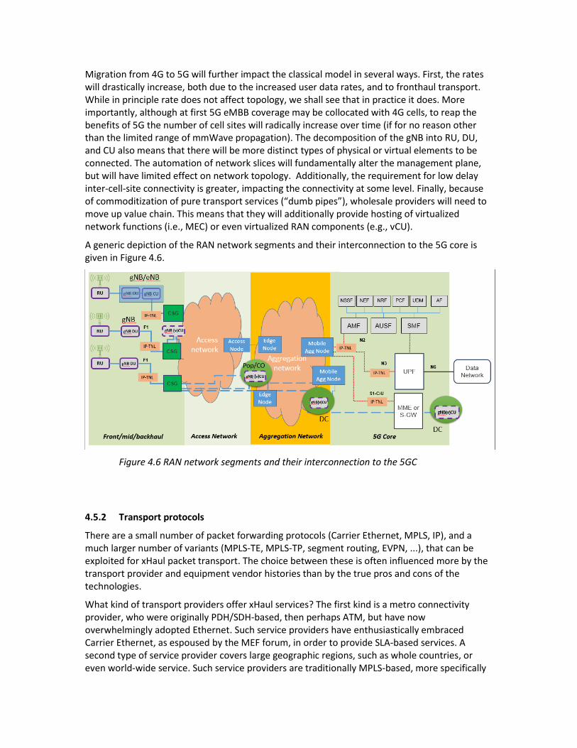
Migration from 4G to 5G will further impact the classical model in several ways. First, the rates will drastically increase, both due to the increased user data rates, and to fronthaul transport. While in principle rate does not affect topology, we shall see that in practice it does. More importantly, although at first 5G eMBB coverage may be collocated with 4G cells, to reap the benefits of 5G the number of cell sites will radically increase over time (if for no reason other than the limited range of mmWave propagation). The decomposition of the gNB into RU, DU, and CU also means that there will be more distinct types of physical or virtual elements to be connected. The automation of network slices will fundamentally alter the management plane, but will have limited effect on network topology. Additionally, the requirement for low delay inter-cell-site connectivity is greater, impacting the connectivity at some level. Finally, because of commoditization of pure transport services (“dumb pipes”), wholesale providers will need to move up value chain. This means that they will additionally provide hosting of virtualized network functions (i.e., MEC) or even virtualized RAN components (e.g., vCU).
A generic depiction of the RAN network segments and their interconnection to the 5G core is given in Figure 4.6.
Figure 4.6 RAN network segments and their interconnection to the 5GC
4.5.2 Transport protocols
There are a small number of packet forwarding protocols (Carrier Ethernet, MPLS, IP), and a much larger number of variants (MPLS-TE, MPLS-TP, segment routing, EVPN, ...), that can be exploited for xHaul packet transport. The choice between these is often influenced more by the transport provider and equipment vendor histories than by the true pros and cons of the technologies.
What kind of transport providers offer xHaul services? The first kind is a metro connectivity provider, who were originally PDH/SDH-based, then perhaps ATM, but have now overwhelmingly adopted Ethernet. Such service providers have enthusiastically embraced Carrier Ethernet, as espoused by the MEF forum, in order to provide SLA-based services. A second type of service provider covers large geographic regions, such as whole countries, or even world-wide service. Such service providers are traditionally MPLS-based, more specifically

supporting the L3VPN [RFC 4364] variety of MPLS, perhaps supplemented with pseudowire services [RFC 3985]. A third kind of provider is typified by electric utilities, who, having excess fiber plant, are willing to lease it at reasonable prices. Since these service providers are actually not networking experts, they tend to offer wavelength service, or piggybacking over whatever mechanisms they already have in place, e.g., flat IP or vanilla MPLS. Finally, we have those operators with an in-house transport division, whose technology tool-kits vary according to their history.
Accordingly we have two traditionally opposing worlds of backhauling based on Carrier Ethernet and MPLS, with a newer possibility of pure IP networks.
MPLS networks, with their local labels rather than network-unique addresses, tend to scale better, and thus second aggregation networks are most often MPLS based. Ethernet technologies can be scaled-up using PBBN techniques (familiarly known as MAC-in-MAC in contrast to the standard service provider labeling called Q-in-Q), but these techniques have not been widely adopted. Hence, MPLS dominates the second aggregation network, when one is present.
On the other hand, Ethernet must be considered a more secure technology for access networks (after all, MPLS packets have no source address which can be authenticated), and additionally (unlike IP and MPLS) define their own physical layer. Hence Ethernet has seen success in the first aggregation segment.
Since core networks also employ MPLS, the idea of seamless MPLS, i.e., stitching together of two MPLS domains has been proposed [draft-ietf-mpls-seamless-mpls]. However, concerns have been voiced about the security of this idea, and in any case the idea is unattractive when two different service providers are involved.
No matter which protocol or combination or protocols is utilized, the transport network must be “carrier grade”, that is, it must be able to guarantee maintenance of specified quality levels. The quality parameters are called Quality of Service (QoS) parameters, and may include data rate, one-way or round-trip delay, packet delay variation, etc. The contract between the customer (mobile operator) and the (wholesale) service provider specifying the precise QoS parameters, their required bounds, and the consequences of not conforming to these bounds is called a Service Level Agreement (SLA). When the transport is not provided by a distinct business entity, the parameters and their values are often called Service Level Objectives (SLOs). The toolkit for monitoring QoS parameters consists of Operations, Administration and Maintenance (OAM) protocols, which in turn are classified as Fault Management (Continuity Check, loopbacks, etc.) and Performance Management (packet loss measurement delay measurement, etc.).
Ethernet was originally a LAN technology, and thus did not require specification of QoS parameters. When Ethernet became a service provided to business customers by Metro-Ethernet Service Providers, it was upgraded to Carrier Ethernet (CE) by specifying QoS parameters, OAM protocols to measure them, management-based route specification, APS mechanisms (including for Ethernet rings) to rapidly recover from failures, and various other carrier grade features.
MPLS was originally a mechanism to accelerate forwarding of IP packets, and thus did not require specification of QoS parameters. It has since been extended in multiple fashions, and we can now distinguish several distinct flavors:
1. Vanilla MPLS is the variety deployed in the core of the Internet to accelerate forwarding. It usually employs LDP signaling to set up Label Switched Paths (LSPs), but is not truly connection-oriented as these LSPs change with routing updates. It may employ Fast ReRoute (FRR) to locally bypass faults.
2. RFC-2547 (more properly now called RFC-4364 [RFC 4364]) is the flavor used to implement L3VPN services for business customers. It sets up LSPs using BGP.
3. MPLS-TE is a true connection-oriented version which reserves resources in order to guarantee SLOs. It does not specify a full OAM suite or APS.
4. MPLS-TP is a transport-network specific flavor. Its defining characteristic is the definition of QoS protocols and true APS (instead of FRR), and may operate without IP forwarding or routing protocols.
5. MPLS-SR is the newest addition. MPLS Segment Routing is implemented by a stack of MPLS labels which are popped in order to reveal the next hop, similar to (now all but deprecated) source routing but without the security issues of enabling an end-user dictate forwarding behavior.
It must be noted that Ethernet defines both the physical (L1) and data-link (L2) layers, while MPLS (as part of the IP suite) does not define a physical layer. Therefore it frequently occurs that MPLS or IP avail themselves of Ethernet for the lower layers. However, we differentiate between this use of Ethernet as a “dumb pipe”, and the use of Carrier Ethernet as a carrier grade networking technology. Yet, it may happen that the differentiation is not clear, with some functionality being carried out in the Ethernet underlay network (e.g., timing, physical layer fault detection, LAG), and other functionalities carried out by the higher layer.
4.5.3 Protocol Stacks for User Traffic
In this section we will detail the construction of the forwarding plane packets as seen in various points in the transport network. For concreteness we will assume in the following that the PDU session type is IP, and that all the data-link and physical interfaces are Ethernet. We will describe packet structure according to the layering convention rather than the packet order convention, so that higher layers appear first, and the rightmost header is the first to be transmitted.
NG-RAN user traffic (e.g. from either DU or CU) is delivered as GTP-U packets, which are themselves encapsulated in UDP/IP (note that 2G and 3G used TDM or ATM, and that these may still be required to be supported). Similarly, signaling traffic is encapsulated as SCTP layer-4 over IP. When these IP packets are the focus of the transport network, we speak of an IP TNL. If these IP packets are further encapsulated in Ethernet layer-2 frames and these are the focus of the transport network, we speak of an Ethernet TNL. For further details on NG-RAN protocols refer to section 3.3.
As a concrete example, in conventional backhauling, packets from a CU destined for the appropriate UPF, are delivered to the transport network as IP/GTP/UDP/IP/Ethernet. Here, the outer (first) “IP” represents the user’s IP datagram including IP header with the UE’s address as source address and the server or peer’s address as destination address, while the inner (second) one is the backhaul IP header with CU’s source address and UPF’s destination address. Note that a single CU may connect to multiple UPFs, and the appropriate UPF depends on the UE’s session.

For the gNB CU/DU split (described in section 4.2), packets from a DU destined for its CU, are delivered to the transport network as PDCP/GTP/UDP/IP/Ethernet, where PDCP represents the (encrypted) user traffic with ROHC compressed headers. The IP is the xHaul IP (SA=DU, DA=CU). Note that a single DU may only connect to a single CU (except for redundancy purposes).
The xHaul network must perform several functions. First and foremost control of forwarding behavior. While the outer IP designates the packet’s ultimate destination, unless the network is trivial there will be multiple possible paths and path parameters (priorities, shaping/policing mechanisms, etc.). Most often the xHaul network will employ a transport tunneling mechanism (unrelated to the mobile network’s GTP tunnels), such as MPLS or GRE, although more recently an approach utilizing segment routing has been proposed. As for any carrier grade network there must be resilience mechanisms, such as APS (possibly with rings) or FRR. Optionally there will be multiple gateways to exit the network. To trigger these mechanisms FM OAM is required, and PM is often needed as well.
It is generally agreed that the first aggregation network does not need to employ MPLS switching (although the packets may carry MPLS labels), so that it will most probably be based on either plain Ethernet with ancillary mechanisms or on CE. For the latter case, S-tagged Q-in-Q VLANs will be used to control the forwarding, resulting in a stack of the type X/GTP/UDP/IP/S-tag/C-tag/Ethernet. If instead an MPLS label stack is inserted to identify tunnels, this instead will be X/GTP/UDP/IP/MPLS/Ethernet. In some cases the transport provider may wish to preserve the user’s Ethernet, in which case an Ethernet pseudowire may be built, resulting in X/GTP/UDP/IP/Ethernet/PW/MPLS/Ethernet (where the first Ethernet header is the user’s and the second is the wholesaler’s), or more generally X/GTP/UDP/IP/Ethernet/PW/MPLS/S-tag/C-tag/Ethernet.
For the case where CE is not used, required carrier grade features are often provided by IP mechanisms, e.g., IS-IS for forwarding behavior, BFD for OAM, IP-FRR for resilience, etc. This requires some tunneling mechanism, most commonly GRE [RFC 2890], although an MPLS label stack may be employed [RFC 4023]. When using GRE the stack will be IP/GTP/UDP/IP/Ethernet/GRE/IP/Ethernet, or IP/GTP/UDP/IP/Ethernet/MPLS/IP/Ethernet where the first IP is the UE’s, the 2nd the BS the third the CSG. More complex cases may be found, for example using VXLAN or other modern tunneling mechanisms.
In fiber-rich environments, and when higher data rates are required (especially for fronthaul), the lower layers may be circuit-switched instead of, or in addition to, packet switched. In such cases Optical Transport Network (OTN) [ITU-T G.709] and Dense Wavelength Division Multiplexing (DWDM) [ITU-T G.694.1] technologies will be employed. The ITU-T is presently studying the application of OTN to 5G transport [ITU-T G Suppl. 67]. Similarly, point-to-point microwave may be used instead of fiber as a constant bit rate transport medium, although such technologies now frequently sport Ethernet interfaces.
Two families of Passive Optical Networks may also be employed at the physical layer. IEEE EPON [clauses 64 and 65 of IEEE 802.3] share much of the standard Ethernet physical layer structure, with modifications (e.g., in the preamble and additional K-codes for Forward Error Correction) and augmentations (such as MultiPoint Control Protocol frames). ITU-T PON flavors [e.g., ITU-T G.989.3] encapsulate Ethernet (and MPLS) in GPON Encapsulation Method (GEM and XGEM) carried in a synchronous bit stream.
The physical layer very often avails itself of point-to-point microwave links (either native Ethernet or TDM based). An emerging elegant solution (attractive for mobile operators

providing their own transport) is integrated access/backhaul (IAB) (described in section 5.2) wherein the 5G air interface and the backhaul share the same wireless technology.
4.5.4 Technology comparison Any comparison of the pros and cons of the different technologies, needs to address the following issues:
1. Scalability 2. Multiservice support 3. Controlling forwarding behavior 4. Support for slicing 5. Resilience 6. Fault management 7. Performance monitoring 8. Security 9. Timing 10. NFV/MEC
which are discussed in the following subsections.
4.5.4.1 Scalability
The problem of scalability in the transport network is much less acute than in the mobile network itself, since there is no awareness of individual end users or devices. In most cases the scale should not exceed hundreds of end points, including the CSGs and ASGs.
4.5.4.2 Multiservice support
No transport network is useful if it can’t transport the required client traffic types. Ethernet carries a wide variety of traffic types via Ethertype marking (or LLC) but does not natively transport TDM, which requires pseudowire extensions [MEF-8]. IP carries different traffic types either directly (via the protocol number or “next header” field) or via layer-four port numbers. MPLS natively carries only IP or MPLS itself (the latter using the label stack) but may transport a wide variety of payloads via pseudowire mechanisms. It should be noted that MPLS packets are not self-describing, and thus there is no way of discovering the traffic type by packet inspection.
Although 3GPP defines three PDU types for 5G, namely, IP, Ethernet and unstructured, and the transport network may handle traffic from various functional split options, in practice all 5G packet transport networks will be required to transport IP over Ethernet. Split 8 fronthaul traffic (not being explicitly specified for 5G) will generally be transported as CPRI [CPRI] over dark fiber or OTN, and the ORAN split 7.2 (see section 4.5) is expected to be much more popular due to its reduced data rate. This latter split may be encapsulated in IP using eCPRI [eCPRI]. Split 2 traffic will be GTP in UDP in IP; split 1 (also not being explicitly specified for 5G) will generally be IP in GTP over UDP/IP; handoff to third party packet networks will avail itself of pure IP. All of these may be carried over the aforementioned alternative lower layers, such as double-tagged Ethernet, MPLS, Ethernet pseudowires over MPLS, and often seemingly ridiculous combinations of these are regularly encountered.
For the foreseeable future CSGs will be required to support 4G (both fronthaul and backhaul), and perhaps 3G (IP or ATM) and even 2G (TDM). In addition non-3GPP IP (e.g. WiFi) and other sources of IP traffic (e.g. residential) may all be in the mix.
Some wholesalers, especially those with carrier Ethernet networks, may prefer not to terminate the Ethernet underlay over which the IP traffic is delivered and employ Ethernet pseudowires [RFC 4448] instead. In such cases, user Ethernet PDUs may be handled natively.
4.5.4.3 Controlling forwarding behavior
It is often the case that network traversal needs to be more nuanced than simply ensuring packet delivery. This most often is the case when there are alternate paths with quite different end-to-end QoS parameters, although other factors may also be influential (e.g., paths with quite different costs). Network slicing obviously requires separation and appropriate forwarding of flows belonging to different slices, and issues specific to it will be discussed in the next subsection.
Two types of path computation are used in the control plane: 1. distributed routing where forwarding devices exchange information between
themselves and each independently builds a Forwarding Information Base (FIB), 2. centralized path computation (network management, SDN) where an omniscient “God
box” uses graph optimization algorithms to compute paths, and disseminates these to the forwarding elements.
Independently of these, two types of QoS handling need to be considered in the forwarding plane:
1. hard QoS (AKA IntServ, Traffic Engineering (TE)) where a combination of Connection Admission Control (CAC) and resource reservation provides hard QoS guarantees,
2. soft QoS (AKA DiffServ, traffic conditioning) where packets are afforded differential treatment according to their priority and discard eligibility, and scheduling/queuing/policing/shaping algorithms provide statistical QoS performance.
Ethernet, IP, and MPLS were all originally best effort (BE) with no QoS handling, but each developed such handling over time. Hard QoS was proposed for VoIP in the form of RSVP, but was never widely used. DiffServ IP is common based on the 6-bit DiffServ Code Point (DSCP) field in the IP header. Carrier Ethernet implements soft QoS based on the 3-bit Priority Code Point (PCP, colloquially called priority bits or P-bits) and Discard Eligibility Indicator (DEI). MPLS-TE adopted the traffic engineering approach by extending RSVP to RSVP-TE [RFC 3209].
Ethernet, IP and MPLS have traditionally utilized various distributed control protocols to learn how to forward, while in Carrier Ethernet traditionally a Network Management System (NMS) configured switch forwarding tables. In MPLS-TE a Path Computation Element (PCE) [RFC 4655] was later added to optimize centralized path computation, and still later Software Defined Networking advocated centralized control of IP and consequent simplification of the forwarding elements to become so-called whitebox switches. Use of SDN for 5G transport networks is described in [ITU-T G.7702].
One advantage of the PCE approach over the related SDN one is that the PCE did not instruct the network elements, leaving the steering function to the source node, while the SDN controller needs to reach out and maintain state with every whitebox switch. Because of this SDN controllers are single points of failure, SDN controller suffer from scalability issues, and even
minor programming bugs in SDN controller code can impact unrelated flows. Recently an alternative called Segment Routing has gained popularity for MPLS and IPv6.
Segment routing, similar to source routing, dictates forwarding by a list of path stations in the packet. Unlike source routing, this list of intermediate addresses is inserted by the ingress router, not by a source host, avoiding the negative security implications of source routing. In MPLS segment routing, the list of intermediate nodes is implemented as a standard MPLS stack, with each LSR popping the top of stack label, rather than swapping it.
4.5.4.4 Support for slicing
A network slice is defined [3GPP TS 23.501, TS 28.530] as a logical network that provides specific network capabilities and network characteristics. Hard isolation slicing refers to the dedicating of resources to a slice instance (such as the assignment of a wavelength on a fiber) while soft isolation slicing refers to isolation of slice instances using shared resources. Soft slice instances can’t exchange packets or directly observe each other, but still may dynamically interact (e.g., due to resource contention). Soft slicing is achieved through logically multiplexing the data-plane over a physical channel, by means of tunneling or pseudowires.
In order for a network slice to conform to its QoS criteria, it needs to be defined end-to-end, i.e., on the air interface, the transport network, and in the core. To support slicing in the transport network the packets need to be classified as belonging to a particular slice. In the case of fronthaul this may not be possible, both because different slices are mixed together in the air interface, and because there may be no easily recognizable identifier for classification (unless slices are differentiated by RF band). In other cases the GTP headers or UDP ports must provide the necessary classification labels. Furthermore, for split 1 different slices may be directed to different UPFs, but at split 2 (the DU/CU split) there is only one CU for a given DU, and thus the different slices need all to be delivered upstream to the same CU, but may traverse different paths or incur different forwarding behaviors at intermediate network elements.
To support a slicing using an Ethernet service, it is necessary to provide a mapping from a 3GPP defined network slice identifier, i.e. Network Slice Selection Assistance Information (NSSAI), to some identifying fields in the Ethernet packet, such as 12-bit VLAN identifier (VID) or the 3-bit PCP. Ethernet VPNs would then constitute a form of soft network slicing. VPN technologies utilize tunneling, isolation of forwarding tables between different tenants, and overlay topology to provide connectivity between different sites of each virtual network. The VPN overlay and the underlay network resources are loosely coupled, and statistical multiplexing still functions to improve network utilization.
Carrier Ethernet supports a palette of isolation types, including [MEF 6.1]:
ELINE – point to point Ethernet service o Ethernet private Line (EPL) – dedicated bandwidth E-LINE service (further
subdivided by [ITU-T G.8011]) o Ethernet Virtual Private Line Service (EVPL) - shared-bandwidth E-LINE
service (i.e., statistical multiplexing of user traffic) (e.g., VPWS)
E-LAN – multipoint to multipoint Ethernet service o EPLAN - dedicated- bandwidth E-LAN service o EVPLAN - shared- bandwidth E-LAN service (e.g., VPLS)
E-TREE (or Ethernet Virtual Private Tree) – point to multipoint Ethernet service.

To support slicing using MPLS the identifying fields can be either the 20-bit label (previously called LLSPs) or the 3-bit Traffic Class (TC) field (ELSPs). Using MPLS-TE one can guaranteed performance (hard QoS) through resource reservation using RSVP-TE [RFC 3209], or by mapping each slice to a physical channel (e.g., wavelength or fiber).
Furthermore, since slicing requires supporting multiple logically self-contained networks over the same transport network [3GPP TS 28.530], the management systems of the mobile (described in section 6.5) and transport networks need to function in harmony to economically attain the performance objectives of each slice instance. This will require cross network interconnection, alignment functions and security mechanisms, which have yet to be standardized.
4.5.4.5 Resilience
High availability mechanisms such as rapid restoration, rings, and FREF are discussed above in the context of the physical layer. In this section we focus on the impact on higher layer protocols. Automatic Protection Switching requires careful protocol work, planning and proper configuration. Historically solutions for both linear protection (i.e., protection over general topologies) and ring protection have been employed.
Ethernet, due to its lacking a Time-To-Live field, disallows rings. Two solution strategies have been proposed:
open loop ring protection methods (e.g., [G.8032]), wherein at any instant in time one link in the ring is blocked, and upon a single link failure the protocol assures that the failed link is the blocked one,
closed loop ring protection methods, whereby some other mechanism, e.g., adding a TTL field, avoids loops.
Open loop mechanisms are generally incompatible with QoS assurance, and closed loop mechanisms have not gained wide acceptance.
For MPLS-TP the IETF has standardized linear protection [RFC 6378] and ring protection [RFC 6974], and the ITU-T has standardized alternative mechanisms [ITU-T G.8131, ITU-T G.8132]. More prevalent is MPLS Fast ReRoute [RFC 4090] that provides a local detour around failed fibers or nodes at the cost of loss of determinism – the end-points are not informed of the local route change.
IP recovers from failures by computing new routes, which is often a lengthy process. Loop Free Alternate Fast Reroute (LFA) [RFC 5286] minimizes downtime by precomputing backup paths (called repair paths) that are guaranteed to be loop free. For IP (MPLS) a Loop Free Alternative to a destination with respect to an element (link/node) for a destination is a router (LSR) that 1) is not the default next hop, 2) is connected to the destination, and 3) does not forward through the element (and hence does not need to know about the failure). In the context of MPLS segment routing, Topology Independent LFA (TI-LFA) allows the source LSR (which knows all the labels from the SR routing protocols) to immediately substitute and alternative MPLS SR label stack. It is Topology Independent in the sense that a loop free backup path is found irrespective of the topologies before and after the failure.
The Replication and Erasure mechanisms (FRER, PREOF) discussed above have been specified by TSN for Ethernet [802.1CB] and are being specified for IP and MPLS by DetNet [RFC 8655].

4.5.4.6 Fault management
Unless the failed element is physically connected to the destination, triggering any of the reliability mechanisms of the previous subsection relies on end-to-end continuity monitoring mechanisms. (Note that Continuity Check (CC) refers to verifying that information sent indeed arrives at the destination, while Connectivity Verification (CV) refers to verifying that information sent to a particular destination does not arrive somewhere else.) These continuously running OAM mechanisms, along with troubleshooting diagnostics (such as loop-backs) that are run when needed, are collectively called fault management (FM). Upon detecting a fault, fault management may trigger control plane functions such as APS or reroute, and management plane functions such as collection of fault statistics, setting off alarms, notification of technical staff, etc. In the following subsection we discuss those OAM functions that monitor less critical operational parameters, and which generally only trigger management plane statistics gathering.
Ethernet, once without any OAM now has multiple standardized FM mechanisms. In particular Connectivity Fault Management [IEEE 802.1ag] and [ITU-T Y.1731] define Continuity Check (CC) heartbeats, as well as loop-back (LB) and link trace (LT) mechanisms. The ITU-T version further defines forward and backward defect indications, locking for diagnostics, and messaging channels for APS. Another ITU-T standard [ITU-T Y.1564] specifies the use of FM when commissioning a new service.
IP and MPLS have a FM protocol known as Bidirectional Forwarding Detection (BFD) [RFC 5880]. Originally a simple keep-alive and loopback (known in BFD as echo) mechanism between two adjacent routers, BFD has expanded to become a full-featured FM protocol, especially in the context of MPLS-TP (which additionally uses LSP-ping for on-demand diagnostics [RFC 6426]).
4.5.4.7 Performance monitoring
Performance Monitoring (PM) means OAM for measurement of QoS parameters that may or may not be important to any particular application. Thus, while CC is critical for any application (no communications-based application can properly function without communications), such parameters as one-way delay (OWD), round-tip-delay (RTD), Packet Delay Variation (PDV) and Packet Loss Ratio (PLR) may or may not be critical for proper functioning of an application.
The ITU-T version of Ethernet OAM (Y.1731) supports both FM and PM, while the IEEE version (802.1ag) supports only FM. IP has one-way and two-way measurement mechanisms, known respectively as OWAMP [RFC 4656] and TWAMP [RFC 5357]. MPLS-TP defines an extensive set of PM functions [RFC 6374] and [RFC 6375].
4.5.4.8 Security 5G presents several new security challenges related to the transport network. The most obvious one is the radical change in trust model due to openness of the core towards third party applications. Related to this are the new use cases and novel network architecture based on distributed telco cloud. Higher number of cells, higher data rates, and lower latencies, all further impact security solutions.
Focusing on the transport network we find that performance issues lurk behind many of these challenges. Denial of service based on overloading physical bit per second rates,

forwarding packet per second rate, cryptographic algorithm resources, or RAN-situated virtualization or computation infrastructure, all need to be addressed in order to avoid bottlenecking the RAN or 5GC resources such as UPF firewall capabilities. This involves both upgrading raw performance to handle worst case scenarios, and detecting and blocking threats at the edge. However, traditional DDoS mitigation approaches may be powerless against truly large scale infected massive MTC attacks, and the conventional approach of redirecting suspicious packets to scrubbing centers may be irrelevant because of latency constraints.
RAN transport protocols play a part here as well. In the forwarding plane it should be noted that while IP and Ethernet packets have source addresses, and thus allow for packet by packet source authentication, MPLS label stacks contain neither destination nor source addresses, and hence necessarily rely on lower or higher layers for this function. In the control plane IP and vanilla MPLS conventionally rely on distributed routing protocols, which facilitate certain attack vectors, while Carrier Ethernet and MPLS-TE traffic steering are configured from a central site in SDN fashion, which expose them to different threats.
Attacks involving undermining virtualized RAN infrastructure (vDU/vCU, MEC) have yet to be adequately researched. Adopting cloud principles may lead to mobile and/or transport operator VNFs running on the same physical platform as third-party application functions, and even completely unrelated computational tasks. While economically attractive multi-tenant hosting introduces novel attack vectors, including denial of service, information leakage (potentially including discovery of passwords, shared secrets and credentials), data manipulation, resource access and even gaining complete platform control. Until lately virtualization technologies were thought to prevent these attacks, but the recent discovery of a plethora of attacks exploiting speculative execution, instruction pipelining, and paged memory have demonstrated that almost all modern CPUs are vulnerable.
4.5.4.9 Timing
We previously discussed the requirements and physical layer aspects of delivering highly accurate timing to base stations over the transport network. For the most stringent requirements the network’s physical layer is utilized for stabilizing frequency (since bit rates are orders of magnitude higher than packet arrival rates) while the upper layers take care of time accuracy with some help from the physical layer.
MPLS and IP can’t provide any of the required physical layer functionalities, simply since they don’t define physical layers. Ethernet defines both layer 1 and layer 2, and is thus almost universally used for on-path support, even when forwarding is performed by a different protocol.
The IETF TICTOC working group seriously considered an MPLS PTP encapsulation, but this never progressed to standard status. The ITU-T telecom profiles [ITU-T G.8265.1, ITU-T G.8275.1, ITU-T G.8275.2] use UDP/IP PTP encapsulations in order to simplifying addressing, but still assume well-engineered networks and the use of on-path support as required; which in most cases is accomplished by means of an Ethernet underlay network (at very least to provide accurate timestamping). While it is extremely advantageous for PTP sync messages to be multicast in large networks, the current ITU-T telecom profiles mandate unicast. However, they do specify automatically configuring slaves with IP addresses of potential master clocks via 1588’s optional unicast discovery mechanism.

4.5.4.10 NFV/MEC
Functionality virtualization is used in mobile networks for three different types of network functions:
1. 3GPP defined network nodes, e.g. AMF, and CU; 2. networking functionalities required by the transport network itself, for example WAN
optimization, FM and PM probes and reflectors; 3. user-centric functionalities such as firewalls, support for location-based services, and
IoT aggregation.
The first of these involves functions belonging to the mobile operator, although the transport provider may provide the computational platform and hosting services. The second function type focuses unambiguously on the needs of the transport provider (reducing costs, increasing automation), and is intended to be transparent to both mobile operator and end-user. The third category directly benefit the end-user, and are frequently marketed by mobile operators, although they may be provided by third parties (a model facilitated by the 5G SBA).
The first type is obviously tightly coupled with the functional split option being used, while the second type is only indirectly influenced by the split (being directly susceptible only to traffic characteristics such as data rate or delay constraints). In some cases type 2 VNFs may be slice-dependent, in which case they must be able to classify traffic to a slice as has been previously discussed.
User functionalities are generally limited to backhauling (split option 1) where user IP packets are discernible. At N3 interfaces these user packets are still transported in GTP-U tunnels, and VASes need to decapsulate (or at least snoop) the GTP. This GTP handling may be performed by a VNF hosted in a CSG which then directs the user traffic to an appropriate server, or the entire functionality may be hosted in the CSG. Alternatively, a MEC platform [ETSI GS MEC 003] may be hosted in a CSG, or a vUPF implemented and afterwards (as part of the 5G core) 5G Application Functions may be similarly hosted [MEC 5G WP].
4.5 Conclusions
5G presents multiple highly inter-related challenges to transport. Numerous technologies, both physical layer and higher layers, are being proposed to meet these challenges. Increased data rates mandate newer physical interfaces, and/or new techniques for bonding physical interfaces, but also impact network topology, forwarding paradigms, and placement of edge computing (MEC) platforms. Reduced latencies necessitate time-sensitive forwarding mechanisms and efficient SDN-based routing, and in some cases dictate MEC processing. Both high data rates and time-sensitive networking impose the requirement for yet more highly accurate time and frequency synchronization. High reliability impacts system design and obligates deploying new resilience mechanisms. Data rate, latency and reliability are all QoS criteria that may need to be monitored, and traded off (e.g., via network slicing). Many of the new requirements and proposed mechanisms entail increased energy consumption, which needs to be countered but yet other means. And all the above mechanisms need to be deployed without introducing new security vulnerabilities.
Non-standalone 4G/5G cases present yet further challenges to the transport segment, for example, integrated Low PHY functionality for converged network elements. Network migration scenarios may be even more challenging as they typically attempt to leverage existing brownfield network infrastructure.

4.6 Bibliography
1588wSyncE Yaakov (J) Stein, Alon Geva, and Gabriel Zigelboim (November 2007), ‘Delivering Better Time-of-Day Using Synchronous Ethernet and 1588’, ITSF-2007
3GPP Technical Report 22.862, ‘Feasibility study on new services and markets technology enablers for critical communications; Stage 1’, www.3gpp.org.
3GPP Technical Specification 23.501, ‘System Architecture for the 5G System; Stage 2’, www.3gpp.org.
3GPP Technical Specification 28.530 ‘Technical Specification Group Services and System Aspects; Management and orchestration; Concepts, use cases and requirements’, www.3gpp.org.
3GPP 36.104 ‘Evolved Universal Terrestrial Radio Access (E-UTRA); Base Station (BS) radio transmission and reception’, www.3gpp.org.
3GPP 38.104 ’NR; Base Station (BS) radio transmission and reception’, www.3gpp.org.
3GPP 38.401 ’NG-RAN; Architecture Description’, www.3gpp.org.
BBF Technical Report TR-221 Technical Specifications for MPLS in Mobile Backhaul Networks
CoDEL Kathleen Nichols, Van Jacobson, Controlling Queue Delay, ACM Queue, May 2012.
CPRI Ericsson AB, Huawei Technologies Co. Ltd, NEC Corporation, Alcatel Lucent and Nokia Siemens Networks GmbH, ‘Common Public Radio Interface (CPRI); Interface Specification v6.0’, August 2013, www.cpri.info.
draft-ietf-rtgwg-segment-routing-ti-lfa S. Litkowski, A. Bashandy, C. Filsfils, B. Decraene, P. Francois, D. Voyer, F. Clad, P. Camarillo, Topology Independent Fast Reroute using Segment Routing, IETF, 2019.
draft-ietf-mpls-seamless-mpls N. Leymann (ed.), Seamless MPLS Architecture, IETF, 2014.
eCPRI Ericsson AB, Huawei Technologies Co. Ltd, NEC Corporation and Nokia, eCPRI Specification V1.0 (2017-08-22) Interface Specification, 2017
ETSI MEC WP ‘Mobile-Edge Computing – Introductory Technical White Paper’, September 2014, www.etsi.org.
MEC 5G WP ‘ETSI White Paper No. 28, MEC in 5G networks, First edition – June 2018’, www.etsi.org.
ETSI GS MEC 003 ‘Multi-access Edge Computing (MEC); Framework and Reference Architecture’, January 2019, www.etsi.org.
IEEE 1588v2 ‘IEEE 1588-2008 - IEEE Standard for a Precision Clock Synchronization Protocol for Networked Measurement and Control Systems’, standards.ieee.org.
IEEE 1588v3 ‘IEEE 1588-2019 - IEEE Standard for a Precision Clock Synchronization Protocol for Networked Measurement and Control Systems’, standards.ieee.org.
IEEE 802.1ag ‘IEEE Standard for Local and Metropolitan Area Networks Virtual Bridged Local Area Networks Amendment 5: Connectivity Fault Management’, now IEEE 802.1Q-2012 clauses 18-22.

IEEE 802.1AX ‘IEEE Standard for Local and metropolitan area networks--Link Aggregation’, December 2014, standards.ieee.org.
IEEE 802.1CB ‘IEEE Standard for Local and metropolitan area networks - Frame Replication and Elimination for Reliability’, September 2017, standards.ieee.org.
IEEE 802.1Qch ‘IEEE Standard for Local and metropolitan area networks - Bridges and Bridged Networks--Amendment 29: Cyclic Queuing and Forwarding’, June 2017, standards.ieee.org.
IEEE 802.3 ‘IEEE Standard for Ethernet’, August 2018, standards.ieee.org.
IEEE 802.3bs ‘IEEE Standard for Ethernet Amendment 10: Media Access Control Parameters, Physical Layers, and Management Parameters for 200 Gb/s and 400 Gb/s Operation’, December 2017, standards.ieee.org.
IEEE 802.3cd ‘IEEE Standard for Ethernet - Amendment 3: Media Access Control Parameters for 50 Gb/s and Physical Layers and Management Parameters for 50 Gb/s, 100 Gb/s, and 200 Gb/s Operation’, February 2019, standards.ieee.org.
ITU-T G.694.1, ‘Spectral grids for WDM applications: DWDM frequency grid’, February 2012, www.itu.int/en/ITU-T/.
ITU-T G.709 ‘Interfaces for the optical transport network’, June 2016, www.itu.int/en/ITU-T/.
ITU-T G.709-Amd3 ‘G.709 Amendment 3’, March 2019 , www.itu.int/en/ITU-T/.
ITU-T G.808.1 ‘Generic protection switching – Linear trail and subnetwork protection’, May 2014, www.itu.int/en/ITU-T/.
ITU-T G.808.2 ‘Generic protection switching – Ring protection’, August 2019, www.itu.int/en/ITU-T/.
ITU-T G.811 ‘Timing characteristics of primary reference clocks’, September 1997, www.itu.int/en/ITU-T/.
ITU-T G.811.1 ‘Timing characteristics of enhanced primary reference clocks’, August 2017, www.itu.int/en/ITU-T/.
ITU-T G.987.x ‘10-Gigabit-capable passive optical network (XG-PON) systems’, www.itu.int/en/ITU-T/.
ITU-T G.989.3 ‘40-Gigabit-capable passive optical networks (NG-PON2): Transmission
convergence layer specification’, October 2015, www.itu.int/en/ITU-T/.
ITU-T G.7702 ‘Architecture for SDN control of transport networks’, March 2018, www.itu.int/en/ITU-T/.
ITU-T G.8011 ‘Ethernet service characteristics’, November 2018, www.itu.int/en/ITU-T/.
ITU-T G.8131 ‘Linear protection switching for MPLS transport profile’, July 2014, www.itu.int/en/ITU-T/.
ITU-T G.8132 ‘MPLS-TP shared ring protection’, August 2017, www.itu.int/en/ITU-T/.
ITU-T G.8262 ‘Timing characteristics of a synchronous equipment slave clock’, January 2015, www.itu.int/en/ITU-T/.
ITU-T G.8265.1 ‘Architecture and requirements for packet-based frequency delivery’, July 2014, www.itu.int/en/ITU-T/.

ITU-T G.8271 ‘Time and phase synchronization aspects of telecommunication networks’, August 2017, www.itu.int/en/ITU-T/.
ITU-T G.8272 ‘Timing characteristics of primary reference time clocks’, November 2018, www.itu.int/en/ITU-T/.
ITU-T G.8272.1 ‘Timing characteristics of enhanced primary reference time clocks’, November 2016, www.itu.int/en/ITU-T/.
ITU-T G.8275.1 ‘Precision time protocol telecom profile for phase/time synchronization with full
timing support from the network’, June 2016, www.itu.int/en/ITU-T/.
ITU-T G.8275.2 ‘Precision time protocol telecom profile for time/phase synchronization with
partial timing support from the network’, June 2016 , www.itu.int/en/ITU-T/.
ITU-T G Suppl. 67 ‘Application of optical transport network Recommendations to 5G transport’, July 2019, www.itu.int/en/ITU-T/.
ITU-T Y.1564 ‘Ethernet service activation test methodology’, February 2016, www.itu.int/en/ITU-T/.
ITU-T Y.1731 ‘Operations, administration and maintenance (OAM) functions and mechanisms
for Ethernet-based networks’, August 2015, www.itu.int/en/ITU-T/.
MEF 6.1 ‘MEF Technical Specification 6.2 Ethernet Services Definitions Phase 2 (April 2008)’,
www.mef.net.
MEF 8 ‘Implementation Agreement for the Emulation of PDH Circuits over Metro Ethernet
Networks (October 2004)’, www.mef.net. MEF 10.3 ‘MEF Technical Specification 10.3 Ethernet Services Attributes Phase 3 (October 2013)’, www.mef.net.
RFC 2475 ‘An Architecture for Differentiated Services’, S. Blake, D. Black, M. Carlson, E. Davies, Z. Wang, W. Weiss. December 1998, www.ietf.org.
RFC 2890 ‘Key and Sequence Number Extensions to GRE’, G. Dommety. September 2000, www.ietf.org.
RFC 3209 ‘RSVP-TE: Extensions to RSVP for LSP Tunnels’, D. Awduche, L. Berger, D. Gan, T. Li, V. Srinivasan, G. Swallow. December 2001, www.ietf.org.
RFC 3985 ‘Pseudo Wire Emulation Edge-to-Edge (PWE3) Architecture’, S. Bryant, Ed., P. Pate, Ed.. March 2005, www.ietf.org.
RFC 4023 ‘Encapsulating MPLS in IP or Generic Routing Encapsulation (GRE)’, T. Worster, Y. Rekhter, E. Rosen, Ed. March 2005, www.ietf.org.
RFC 4090 Fast Reroute Extensions to RSVP-TE for LSP Tunnels. P. Pan, Ed., G. Swallow, Ed., A. Atlas, Ed. May 2005, www.ietf.org.
RFC 4364 ‘BGP/MPLS IP Virtual Private Networks (VPNs)’, E. Rosen, Y. Rekhter. February 2006, www.ietf.org.
RFC 4448 ‘Encapsulation Methods for Transport of Ethernet over MPLS Networks‘, L. Martini, Ed., E. Rosen, N. El-Aawar, G. Heron. April 2006, www.ietf.org.
RFC 4655 ‘A Path Computation Element (PCE)-Based Architecture‘, A. Farrel, J.-P. Vasseur, J. Ash. August 2006, www.ietf.org.

RFC 4656 A One-way Active Measurement Protocol (OWAMP). S. Shalunov, B. Teitelbaum, A. Karp, J. Boote, M. Zekauskas. September 2006, www.ietf.org.
RFC 5286 ‘Basic Specification for IP Fast Reroute: Loop-Free Alternates‘, A. Atlas, Ed., A. Zinin, Ed. September 2008, www.ietf.org.
RFC 5357 ‘A Two-Way Active Measurement Protocol (TWAMP)’, K. Hedayat, R. Krzanowski, A. Morton, K. Yum, J. Babiarz. October 2008, www.ietf.org.
RFC 5880 Bidirectional Forwarding Detection (BFD). D. Katz, D. Ward. June 2010, www.ietf.org.
RFC 6374 ‘Packet Loss and Delay Measurement for MPLS Networks‘, D. Frost, S. Bryant. September 2011, www.ietf.org.
RFC 6375 A Packet Loss and Delay Measurement Profile for MPLS-Based Transport Networks. D. Frost, Ed., S. Bryant, Ed. September 2011, www.ietf.org.
RFC 6378 ‘MPLS Transport Profile (MPLS-TP) Linear Protection‘, Y. Weingarten, Ed., S. Bryant, E. Osborne, N. Sprecher, A. Fulignoli, Ed.. October 2011, www.ietf.org.
RFC 6426 ‘MPLS On-Demand Connectivity Verification and Route Tracing‘, E. Gray, N. Bahadur, S. Boutros, R. Aggarwal. November 2011, www.ietf.org.
RFC 6974 ‘Applicability of MPLS Transport Profile for Ring Topologies‘, Y. Weingarten, S. Bryant, D. Ceccarelli, D. Caviglia, F. Fondelli, M. Corsi, B. Wu, X. Dai. July 2013, www.ietf.org.
RFC 8578 ‘Deterministic Networking Use Cases’, E. Grossman, Ed. May 2019, www.ietf.org.
RFC 8655 ‘Deterministic Networking Architecture’, N. Finn, P. Thubert, B. Varga, J. Farkas. Oct 2019, www.ietf.org US 9,276,689 US patent ‘PLUGGABLE MASTER CLOCK’, March 2016, Alon Geva and Yaakov Stein.