chapter 4: composite pre-processing - altair...
TRANSCRIPT

Copyright © 2009 Altair Engineering, Inc. Proprietary and Confidential. All rights reserved.
Chapter 4: Composite Pre-Processing

Copyright © 2009 Altair Engineering, Inc. Proprietary and Confidential. All rights reserved.
Agenda – Chapter 4: Composite Pre-Processing
4. Modeling of Composites in Finite Element Environments
4.1 Ply-Based Laminate Modeling Concept
4.2 How to Setup Composites in HyperMesh
4.3 Designing Composite using HyperLaminate
Exercise 4.1 PCOMP
Exercise 4.2 PCOMPG
Exercise 4.3 PCOMPP

Copyright © 2009 Altair Engineering, Inc. Proprietary and Confidential. All rights reserved.
Chapter 4: Modeling of Composites in Finite Element Environments

Copyright © 2009 Altair Engineering, Inc. Proprietary and Confidential. All rights reserved.
Agenda – Chapter 4: Composite Pre-Processing
4. Modeling of Composites in Finite Element Environments
4.1 Ply-Based Laminate Modeling Concept
4.2 How to Setup Composites in HyperMesh
4.3 Designing Composite using HyperLaminate
Exercise 4.1 PCOMP
Exercise 4.2 PCOMPG
Exercise 4.3 PCOMPP

Copyright © 2009 Altair Engineering, Inc. Proprietary and Confidential. All rights reserved.
Chapter 4: Modeling of Composite
Modeling of Composites in Finite Element Environments
Composites can be modeled using single layer shells, multi-layer shells
(continuum shells) and/or solids.
In case of solids, each ply needs to be modeled with at least one solid
element. This requires a huge number of solid elements to model a simple
plate.
Majority of the real life parts are modeled with single layer shell elements.
Analysis of composite shells is very similar to the solution of standard shell
elements. An single layer shell element is modeled as composite by assigning a composite property (e.g. PCOMP, PCOMPG or PCOMPP) to it.
Composite material properties in general are modeled with an orthotropic
material model (e.g. MAT8 - NASTRAN Solver ).

Copyright © 2009 Altair Engineering, Inc. Proprietary and Confidential. All rights reserved.
Core 10 mm
2 mm
2 mm
Sandwich Modeling Idealization
Core: Isotropic
• E = 20 MPa
• G = 0.45
Plies: Isotropic
• E = 73,000 MPa
• G = 0.18

Copyright © 2009 Altair Engineering, Inc. Proprietary and Confidential. All rights reserved.
PCOMP3 Layers
PSHELL
PSOLID
PSHELL
PSHELL
PSOLID
PSHELL
Sandwich Modeling Idealization

Copyright © 2009 Altair Engineering, Inc. Proprietary and Confidential. All rights reserved.
Displacement plot
PCOMP
3 layers
PSHELLPSOLID
PSHELL
PSHELLPSOLID
PSHELL
Sandwich Modeling Idealization

Copyright © 2009 Altair Engineering, Inc. Proprietary and Confidential. All rights reserved.
RADIOSS shell elements use FSDT.
Even for thick shell, the hypothesis that a straight line normal to the middle plane remains straight still holds.
In reality, with a soft solid in the middle, the actual deformation is more ‘zigzag’.
Subdividing the solid into 3 layers is not very beneficial here - one solid with two shells suffices to approximate the above ‘zigzag’.
Sandwich Modeling Idealization

Copyright © 2009 Altair Engineering, Inc. Proprietary and Confidential. All rights reserved.
Sandwich Modeling Idealization

Copyright © 2009 Altair Engineering, Inc. Proprietary and Confidential. All rights reserved.
Chapter 4.1: Ply-Based Laminate Modeling
Copyright © 2009 Altair Engineering, Inc. Proprietary and Confidential. All rights reserved.
Agenda – Chapter 4: Composite Pre-Processing
4. Modeling of Composites in Finite Element Environments
4.1 Ply-Based Laminate Modeling Concept
4.2 How to Setup Composites in HyperMesh
4.3 Designing Composite using HyperLaminate
Exercise 2.1 PCOMP
Exercise 2.2 PCOMPG
Exercise 2.3 PCOMPP

Copyright © 2009 Altair Engineering, Inc. Proprietary and Confidential. All rights reserved.
Different choice for PROPERTY definitions – PCOMP
• Homogenization performed in preprocessor
• No associativity between PCOMPs
(1) (2) (3) (4) (5) (6) (7) (8) (9) (10)
PCOMP PID Z0 NSM SB FT TREF GE LAM
MID1 T1 THETA1 SOUT1 MID2 T2 THETA2 SOUT2
MID3 T3 THETA3 SOUT3 etc. …
… …
DS
Ply-Based Laminate Modeling Concept
Copyright © 2009 Altair Engineering, Inc. Proprietary and Confidential. All rights reserved.
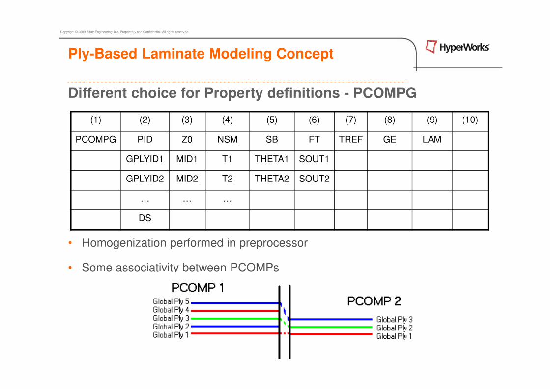
Different choice for Property definitions - PCOMPG
• Homogenization performed in preprocessor
• Some associativity between PCOMPs
(1) (2) (3) (4) (5) (6) (7) (8) (9) (10)
PCOMPG PID Z0 NSM SB FT TREF GE LAM
GPLYID1 MID1 T1 THETA1 SOUT1
GPLYID2 MID2 T2 THETA2 SOUT2
… … …
DS
Ply-Based Laminate Modeling Concept

Copyright © 2009 Altair Engineering, Inc. Proprietary and Confidential. All rights reserved.
Ply-Based Laminate Modeling Concept
Different choice for PROPERTY definitions - PCOMP - PCOMPG

Copyright © 2009 Altair Engineering, Inc. Proprietary and Confidential. All rights reserved.
Different choice for PROPERTY definitions – PCOMP
PCOMP defines all the laminate properties like ply material, thickness and orientation and also the stacking sequence in ONE Property Card.
PCOMP definition contains no information on plies that are also part of
other regions (PCOMPs). During post-processing, this requires lot of book keeping to track ply and stacking information for each PCOMP.
Chapter 2: Composite Pre-processing - Analysis

Copyright © 2009 Altair Engineering, Inc. Proprietary and Confidential. All rights reserved.
Different choice for Property definitions - PCOMPG
PCOMPG is similar to PCOMP and additionally it stores global ply identification number.
Through the global ply identification number, plies that are part of many regions can be tracked across the regions, reducing the effort for keeping track of the ply properties and stacking information.
Chapter 2: Composite Pre-processing - Analysis
Copyright © 2009 Altair Engineering, Inc. Proprietary and Confidential. All rights reserved.
Chapter 2: Composite Pre-processing - Analysis
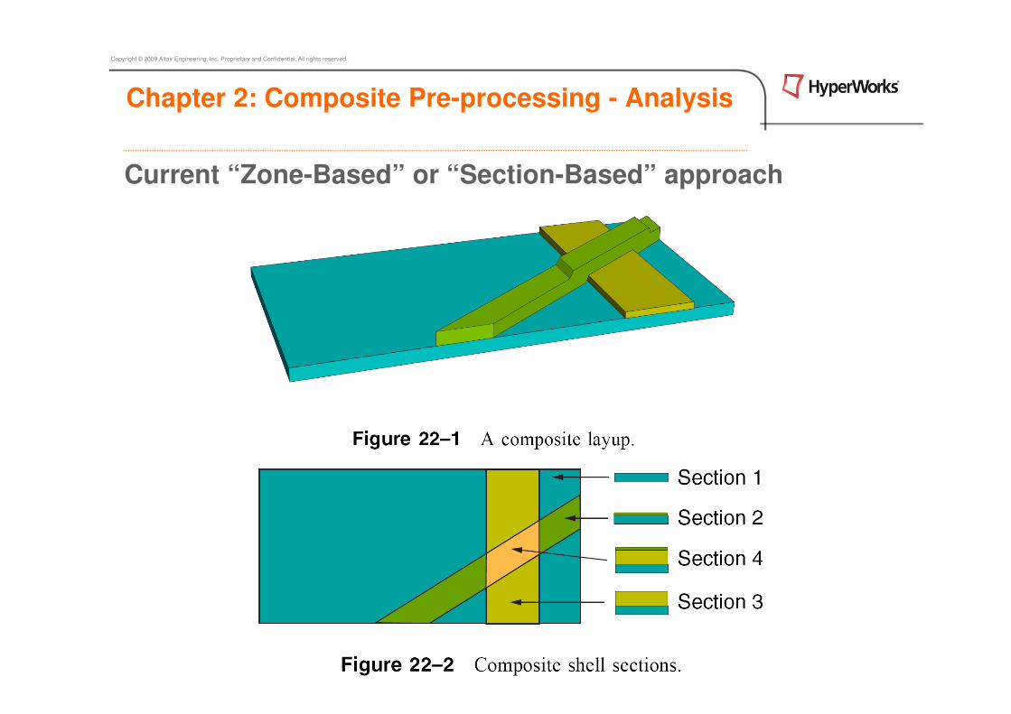
Current “Zone-Based” or “Section-Based” approach

Copyright © 2009 Altair Engineering, Inc. Proprietary and Confidential. All rights reserved.
Current “Zone-Based” or “Section-Based” approach
• Treating laminated composites like metals
• Ignoring ply-based nature of laminated composites
Ply-Based Laminate Modeling Concept

Copyright © 2009 Altair Engineering, Inc. Proprietary and Confidential. All rights reserved.
Current “Zone-Based” composite modeling approach
Disadvantages
• 5 Plies in this simple example create 9 Zones (data to be handled)
• Ply thicknesses are not interconnected (so a thickness change can be a
large book-keeping effort)
• Adding a new ply requires re-zoning effort, which can be considerable
Ply-Based Laminate Modeling Concept

Copyright © 2009 Altair Engineering, Inc. Proprietary and Confidential. All rights reserved.
Current “Zone-Based” composite modeling approach
Adding an new ply requires much effort in re-zoning elements and re-meshing
is often required.
Ply-Based Laminate Modeling Concept

Copyright © 2009 Altair Engineering, Inc. Proprietary and Confidential. All rights reserved.
Ply-Based Laminate Modeling Concept
New ply-based composite modeling approach

Copyright © 2009 Altair Engineering, Inc. Proprietary and Confidential. All rights reserved.
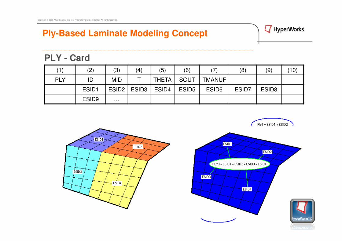
PLY - Card
STACK - Card
PCOMPP - Card
(1) (2) (3) (4) (5) (6) (7) (8) (9) (10)
STACK ID LAM PLYID1 PLYID2 PLYID3 PLYID4 PLYID5 PLYID6
PLYID7 …
(1) (2) (3) (4) (5) (6) (7) (8) (9) (10)
PLY ID MID T THETA SOUT TMANUF
ESID1 ESID2 ESID3 ESID4 ESID5 ESID6 ESID7 ESID8
ESID9 …
(1) (2) (3) (4) (5) (6) (7) (8) (9) (10)
PCMOPP PID Z0 NSM SB FT TREF GE
Ply-Based Laminate Modeling Concept
Copyright © 2009 Altair Engineering, Inc. Proprietary and Confidential. All rights reserved.
PLY - Card
(1) (2) (3) (4) (5) (6) (7) (8) (9) (10)
PLY ID MID T THETA SOUT TMANUF
ESID1 ESID2 ESID3 ESID4 ESID5 ESID6 ESID7 ESID8
ESID9 …
Ply-Based Laminate Modeling Concept

Copyright © 2009 Altair Engineering, Inc. Proprietary and Confidential. All rights reserved.
STACK – Card
Please show and explain : HW10.0 HELP – Stack Card
(1) (2) (3) (4) (5) (6) (7) (8) (9) (10)
STACK ID LAM PLYID1 PLYID2 PLYID3 PLYID4 PLYID5 PLYID6
PLYID7 …
Ply-Based Laminate Modeling Concept
Copyright © 2009 Altair Engineering, Inc. Proprietary and Confidential. All rights reserved.
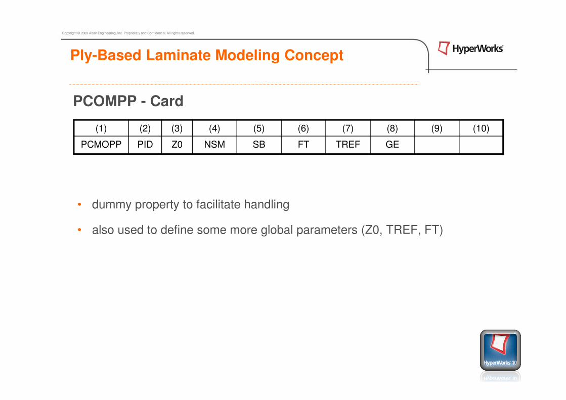
PCOMPP - Card
• dummy property to facilitate handling
• also used to define some more global parameters (Z0, TREF, FT)
Ply-Based Laminate Modeling Concept
(1) (2) (3) (4) (5) (6) (7) (8) (9) (10)
PCMOPP PID Z0 NSM SB FT TREF GE

Copyright © 2009 Altair Engineering, Inc. Proprietary and Confidential. All rights reserved.
Ply-Based Laminate Modeling Concept• PLY – Global Ply Data and Elements Defining Global Ply
• STACK - “glues” PLYs into a Laminate with Order
• PCOMPP – implicit through STACK and PLYs (replacing PCOMP/G)
PLY 1 MID THK THETA SOUT ELEMENTs (e.g. 0° )
PLY 2 MID THK THETA SOUT ELEMENTs (e.g. 90°)
PLY 3 MID THK THETA SOUT ELEMENTs (e.g. 0° )
PLY 4 MID THK THETA SOUT ELEMENTs (e.g. 45°)
PLY …
STACK 1 SYM PLY1 PLY2 ….
Ply-Based Laminate Modeling Concept

Copyright © 2009 Altair Engineering, Inc. Proprietary and Confidential. All rights reserved.
Ply-Based Laminate Modeling Concept
Left flange [11 12 13 14 21 22 23 24]Right flange [11 12 13 14 31 32 33 34]Web [24 23 22 21 41 42 43 31 32 33 34]
Conflicting stacking sequences!
STACK 100
+ SUB 1 top 11 12 13 14
+ SUB 2 left 21 22 23 24
+ SUB 3 right 31 32 33 34
+ SUB 4 mid 41 42 43
+ INT 14 21
+ INT 14 31
+ INT 21 41
+ INT 43 31
STACK Card – SUBlaminate & INTerfaces
• Required to model structures such as T- or I-Beams where the stacking sequence cannot be uniquely defined by a simple STACK card
• Intuitive definition reflecting the manufacturing process

Copyright © 2009 Altair Engineering, Inc. Proprietary and Confidential. All rights reserved.
STACK Card – SUBlaminate & INTerfaces
• Substacks (SUB) define partial stacking sequences
• Interfaces (INT) indicate how the substacks are assembled
• During ply stacking optimization, substacks are shuffled independently as to avoid undesirable ‘penetration’ effects
Ply-Based Laminate Modeling Concept
STACK 100
+ SUB 1 top 11 12 13 14
+ SUB 2 left 21 22 23 24
+ SUB 3 right 31 32 33 34
+ SUB 4 mid 41 42 43
+ INT 14 21
+ INT 14 31
+ INT 21 41
+ INT 43 31

Copyright © 2009 Altair Engineering, Inc. Proprietary and Confidential. All rights reserved.
STACK Card – SUBlaminate & INTerfaces• Supported as control card
• PLY based composite entities
• To create multiple STACKs use pull-down or solver browser
Setup -> Create -> Stack
Ply-Based Laminate Modeling Concept

Copyright © 2009 Altair Engineering, Inc. Proprietary and Confidential. All rights reserved.
Draping accommodation
• Each element may be assigned ∆θ and ∆T for each ply individually
PLY – Card
DRAPE - Card
(1) (2) (3) (4) (5) (6) (7) (8) (9) (10)
PLY ID MID T THETA SOUT TMANUF DRID
ESID1 ESID2 ESID3 ESID4 ESID5 ESID6 ESID7 ESID8
ESID9 …
Ply-Based Laminate Modeling Concept
(1) (2) (3) (4) (5) (6) (7) (8) (9) (10)
DRAPE DRID

Copyright © 2009 Altair Engineering, Inc. Proprietary and Confidential. All rights reserved.
DRAPE – Card
• Draped half-sphere after importing data from ANAGLYPH Laminate Tools
Ply-Based Laminate Modeling Concept
(1) (2) (3) (4) (5) (6) (7) (8) (9) (10)
DRAPE DRID
ELEM 123 1.000000 90.55610

Copyright © 2009 Altair Engineering, Inc. Proprietary and Confidential. All rights reserved.
Agenda – Chapter 4: Composite Pre-Processing
4. Modeling of Composites in Finite Element Environments
4.1 Ply-Based Laminate Modeling Concept
4.2 How to Setup Composites in HyperMesh
4.3 Designing Composite using HyperLaminate
Exercise 4.1 PCOMP
Exercise 4.2 PCOMPG
Exercise 4.3 PCOMPP

Copyright © 2009 Altair Engineering, Inc. Proprietary and Confidential. All rights reserved.
Chapter 4: Composite Pre-processing
How to Setup a Composite in HyperMesh (I)
1. Import or create the 2D geometry that will represent your component.
2. Organize your model in components
3. Generate the Mesh.

Copyright © 2009 Altair Engineering, Inc. Proprietary and Confidential. All rights reserved.
Chapter 4: Composite Pre-processing
How to Setup a Composite in HyperMesh (II)
4. Align the elements according to the laminate main direction
• TETA (Angle that the element needs to be rotate from definition)
• MCID (Local coordinate system)
• Both are defined as the (7th field for CQUAD or 6th field for CTRIA)
5. Define the composite materials.
Don’t forget about the normals !!!
Copyright © 2009 Altair Engineering, Inc. Proprietary and Confidential. All rights reserved.
Chapter 4: Composite Pre-processing
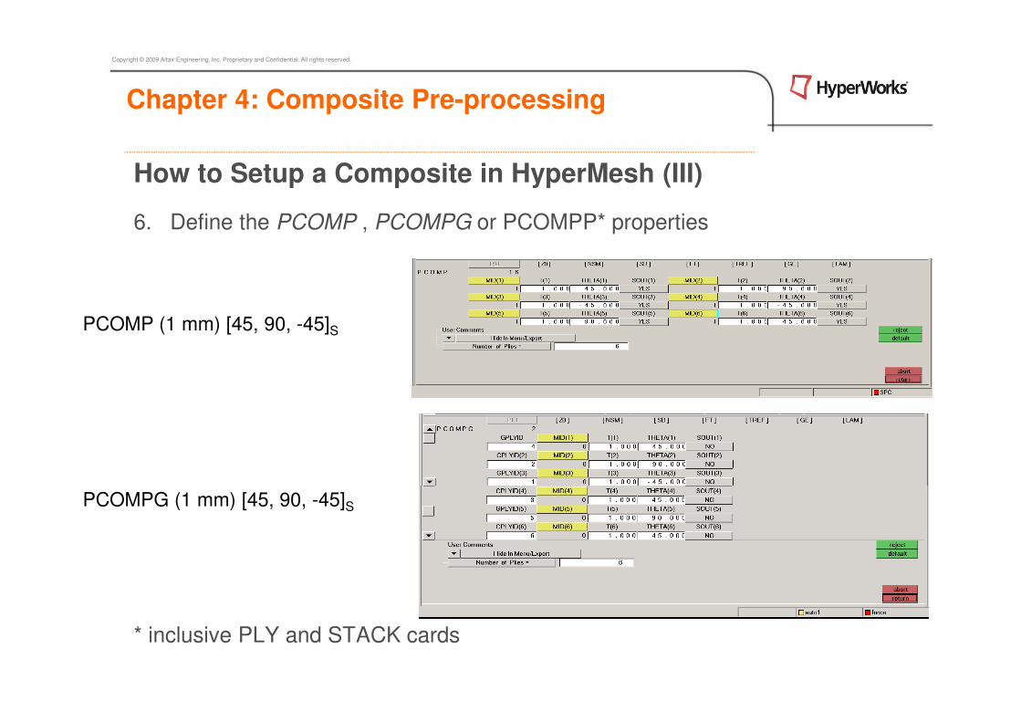
How to Setup a Composite in HyperMesh (III)
6. Define the PCOMP , PCOMPG or PCOMPP* properties
* inclusive PLY and STACK cards
PCOMP (1 mm) [45, 90, -45]S
PCOMPG (1 mm) [45, 90, -45]S

Copyright © 2009 Altair Engineering, Inc. Proprietary and Confidential. All rights reserved.
Chapter 4: Composite Pre-processing
How to Setup a Composite in HyperMesh (IV)
7. Assign the properties to the components.
8. Apply the boundary conditions. (SPC)
9. Apply the loads. (Load)
Loads applied to
geometry to simply the
display !!!

Copyright © 2009 Altair Engineering, Inc. Proprietary and Confidential. All rights reserved.
Chapter 4: Composite Pre-processing
How to Setup a Composite in HyperMesh (V)
10. Create the load step with the constraints and loads.
11. Run the analysis
12. Post-processing

Copyright © 2009 Altair Engineering, Inc. Proprietary and Confidential. All rights reserved.
Composite Pre-Processing – In Detail

Copyright © 2009 Altair Engineering, Inc. Proprietary and Confidential. All rights reserved.
Chapter 2: Composite Pre-processing - Analysis
Parameters for modeling composites
Define material properties (MAT8)
• Ply, matrix and core (HOMOGENIZATION)
Define the material coordinate system to establish the reference for defining
the ply angle
Define the element normal to establish the reference for defining ply stacking
Define the individual laminate property (PCOMP)
• Ply material, Ply thickness (number of plies), Ply angle, Order of stacking

Copyright © 2009 Altair Engineering, Inc. Proprietary and Confidential. All rights reserved.
Chapter 2: Composite Pre-processing - Analysis
Modeling Flow
Element(CQUAD4 )
Element Property(PCOMP)failure theory
Material Property(MAT8)
Material Orientation
Element Normal

Copyright © 2009 Altair Engineering, Inc. Proprietary and Confidential. All rights reserved.
Chapter 2: Composite Pre-processing - Analysis
The typical material model used for composites is MAT8, which is planar
orthotropic material.
Each ply is associated with a material property.
The use of isotropic MAT1 or general anisotropic MAT2 for ply properties is also supported.
Material Property(MAT8)

Copyright © 2009 Altair Engineering, Inc. Proprietary and Confidential. All rights reserved.
Chapter 2: Composite Pre-processing - Analysis
Definition of material property, MAT8 in Hypermesh
E1 = 18.7e6 psi υ12 = υ13= 0.3 G12 = G13 = 0.5e6psi a1 = 1.0e-7 in/in/oC
E2 = E3 = 1.4e6 psi υ23 = 0.6 G23 = 0.45e6 psi a2 = a3 = 18.0e-6 in/in/oC
Material Property(MAT8)
Copyright © 2009 Altair Engineering, Inc. Proprietary and Confidential. All rights reserved.
Chapter 2: Composite Pre-processing - Analysis
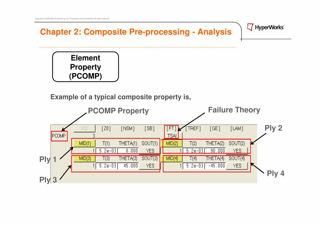
Example of a typical composite property is,
Element Property(PCOMP)
PCOMP Property Failure Theory
Ply 3
Ply 1
Ply 4
Ply 2

Copyright © 2009 Altair Engineering, Inc. Proprietary and Confidential. All rights reserved.
Chapter 2: Composite Pre-processing - Analysis
Element’s normal direction defines the stacking sequence.
Plies are listed from the bottom surface upwards, with respect to the
element’s normal direction
Element Normal
Copyright © 2009 Altair Engineering, Inc. Proprietary and Confidential. All rights reserved.
Chapter 2: Composite Pre-processing - Analysis
• The material orientation is important to establish the reference for ply angles. Ply angles can be specified relative to a
a) element coordinate system,
b) vector projected onto elements,
c) coordinate system.
• Since element coordinate system is strongly dependent upon the node
numbering in individual elements, it is advisable to prescribe a coordinate system for composite elements and specify ply angles relative to this
system.
Material Orientation

Copyright © 2009 Altair Engineering, Inc. Proprietary and Confidential. All rights reserved.
Chapter 2: Composite Pre-processing - Analysis
Material Orientation
• 2D -> composites panel, allows the user to define, review or modify the
material orientation for elements.
• Individual ply orientation can also be reviewed by selecting ply number.
Material Orientation by default(based on element node numbering)
Material Orientation by specifying Material orientation angle

Copyright © 2009 Altair Engineering, Inc. Proprietary and Confidential. All rights reserved.
Sample material property is defined as E1 = 1.3e5 Mpa E2 = E3 = 9650 Mpa
υ12 = υ13 = 0.3 υ23 = 0.6
G12 = G13 = 3450 Mpa G23 = 3100 MPa
a1 = 1.0e-7mm/mm/oC a2 = a3 = 18.0e-6 mm/mm/oC
E1 is much stronger than E2 . But, in which directions are E1 and E2 measured?
Material orientation is very important because it defines the direction for E1 and
E2. It also establishes the reference for the definition of ply angle.
Why is Material orientation is very important?
Chapter 2: Composite Pre-processing - Analysis

Copyright © 2009 Altair Engineering, Inc. Proprietary and Confidential. All rights reserved.
Chapter 2: Composite Pre-processing - Analysis
Why is Material orientation is very important?

Copyright © 2009 Altair Engineering, Inc. Proprietary and Confidential. All rights reserved.
Understanding different coordinate systems
There are many coordinate systems like:
• global coordinate system,
• local coordinate systems,
• element coordinate systems,
• material coordinate systems, …
There is always only one global coordinate system which is the reference
for all other coordinate systems.
Direction for E1 is the x-axis of the element’s material coordinate system
and direction for E2 corresponds to its y-axis.
Chapter 2: Composite Pre-processing - Analysis

Copyright © 2009 Altair Engineering, Inc. Proprietary and Confidential. All rights reserved.
Understanding the element coordinate system
For anisotropic elements by default the material coordinate system is aligned with the element coordinate system.
The x-axis of the element coordinate is aligned with side 1-2 (or direction
from G1 → G2) of the shell element and z-axis is aligned with the normal
of the shell element.
Chapter 2: Composite Pre-processing - Analysis

Copyright © 2009 Altair Engineering, Inc. Proprietary and Confidential. All rights reserved.
Material coordinate system
• Material orientation by default (based on element node numbering) may not
be aligned properly.
• Material coordinate system should be
defined to align the E1 and E2 to the desired
direction.
• Material coordinate system can be defined
by defining an angle or a
coordinate system.
Chapter 2: Composite Pre-processing - Analysis

Copyright © 2009 Altair Engineering, Inc. Proprietary and Confidential. All rights reserved.
Material coordinate system
Material orientation can be defined as an angle Rotated by THETA from the
x axis of the element coordinate system.
THETA = 90 degree
• X (G1 → G2) Rotated by THETA
• Z = Element Normal
• MCID: X is defined by the local coordinate system.
Chapter 2: Composite Pre-processing - Analysis

Copyright © 2009 Altair Engineering, Inc. Proprietary and Confidential. All rights reserved.
Agenda – Chapter 4: Composite Pre-Processing
4. Modeling of Composites in Finite Element Environments
4.1 Ply-Based Laminate Modeling Concept
4.2 How to Setup Composites in HyperMesh
4.3 Designing Composite using HyperLaminate
Exercise 2.1 PCOMP
Exercise 2.2 PCOMPG
Exercise 2.3 PCOMPP
Copyright © 2009 Altair Engineering, Inc. Proprietary and Confidential. All rights reserved.
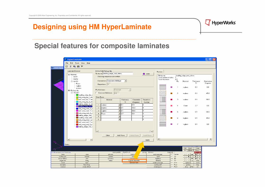
Special features for composite laminates
Designing using HM HyperLaminate

Copyright © 2009 Altair Engineering, Inc. Proprietary and Confidential. All rights reserved.
Designing using HM HyperLaminate

Copyright © 2009 Altair Engineering, Inc. Proprietary and Confidential. All rights reserved.
Agenda – Chapter 4: Composite Pre-Processing
4. Modeling of Composites in Finite Element Environments
4.1 Ply-Based Laminate Modeling Concept
4.2 How to Setup Composites in HyperMesh
4.3 Designing Composite using HyperLaminate
Exercise 2.1 PCOMP
Exercise 2.2 PCOMPG
Exercise 2.3 PCOMPP

Copyright © 2009 Altair Engineering, Inc. Proprietary and Confidential. All rights reserved.
Altair HyperWorks 10.0: A Platform for Innovation