chapter 4 imaging of ocular and adnexal trauma
TRANSCRIPT

61
Imaging of Ocular and Adnexal Trauma
Chapter 4
IMAGING OF OCULAR ANDADNEXAL TRAUMA
JEFFREY P. BLICE, MD*
INTRODUCTION
IMAGING MODALITIESPlain Skull FilmsComputed TomographyMagnetic Resonance ImagingUltrasonography
SPECIFIC TRAUMATIC INJURIES AND IMAGINGIntraorbital and Intraocular Foreign BodiesOrbital FracturesBlunt Ocular Trauma
SUMMARY
*Commander, Medical Corps, US Navy, Department of Ophthalmology, National Naval Medical Center, 8901 Wisconsin Avenue, Bethesda,Maryland 20889-5600

62
Ophthalmic Care of the Combat Casualty
INTRODUCTION
Various imaging modalities exist to aid in theinitial and subsequent evaluation of trauma involv-ing the eye and orbit. However, the best imagingmodality for the initial evaluation of eye traumaremains indirect ophthalmoscopy. In the first hoursafter a severe injury, the first examiner can obtaininformation with a level of detail that no other im-aging method can provide. Although the early viewmay not always be the best one, often the first lookinto a traumatized eye is the only look.
Standard roentgenography, computed tomogra-phy (CT), magnetic resonance imaging (MRI), andultrasonography all have their strengths and weak-nesses. They can be useful adjuncts in the manage-ment of globe ruptures, intraocular foreign bodies(IOFBs), and facial and skull fractures.
Before beginning the discussion of available im-aging methods, a brief review of orbital anatomy isin order. The orbit is pyramidal in shape, with thebase oriented anteriorly and the apex posteriorly.The orbital walls consist of seven bones: the max-illa, zygoma, sphenoid, palatine, ethmoid, lacrimal,
and frontal. The roof of the orbit is composedmainly of the frontal bone, with a small contribu-tion from the sphenoid bone. Laterally, the zygomaand greater wing of the sphenoid provide the ma-jor component of the wall. Both the lateral and su-perior walls of the orbit are strong, but the inferiorand medial walls have thinner bones and are morelikely to be damaged from trauma. Inferiorly, thezygoma and thin roof of the maxilla form the majorportion of the floor, and the palatine bone contrib-utes posteriorly. The medial wall is formed from thefrontal (superiorly), the sphenoid (posteriorly), thelacrimal (inferiorly and anteriorly), and the thin-walled ethmoid (centrally). The thin walls of themaxilla and ethmoid make these bones particularlysusceptible to trauma from compression of the or-bital contents or transmitted force applied to theorbital rim.
The optic canal is formed entirely from the lesser wingof the sphenoid. A traumatic injury resulting in dis-located bone fragments from the sphenoid can im-pinge on the optic nerve, resulting in a neuropathy.
IMAGING MODALITIES
Plain Skull Films
Although largely replaced now by CT scans,plain skull films (ie, roentgenography) can still pro-vide useful information in the evaluation of trau-matic injuries. It is likely that CT will not be easilyaccessible in a deployed medical unit; consequently,plain films of the skull may be the only imagingmethod available. The occipitofrontal, lateral,occipitooral, and oblique are the standard projec-tions used to evaluate the orbit.
The occipitofrontal view, also called Caldwell’sview or the anteroposterior (AP) view, provides aview of the size and shape of the orbit, the orbitfloor, zygomaticofrontal suture, and laminapapyracea. The lateral view demonstrates the sellaturcica, anterior and posterior clinoids, anterior andposterior walls of the frontal sinus, sphenoid sinus,and nasopharyngeal soft tissues. The occipitooral,or Waters’s, view provides the best projection of themaxillary antra and inferior orbital rim. Obliqueviews are used to assess the shape and diameter ofthe optic canal, which has a normal range from 4.4to 6.0 mm in diameter (Table 4-1).1
Plain films are relatively inexpensive and almostuniversally available; soft-tissue definition, how-ever, is poor. Localization of foreign bodies (FBs) is
unreliable without more-involved methods of im-aging. Specifically, suturing a limbal ring to the eyeand repeating AP and lateral views allow a radi-ologist to chart the position of an FB within theglobe.2 In instances of multiple radiopaque FBs,plain films permit a rapid assessment of the num-ber and shape of the objects.
Computed Tomography
A CT image is a mathematical reconstruction ofdata obtained from multiple radiographic projec-tions of an object. The basic principle of the CT scaninvolves an X-ray source and an array of detectorsmounted in a gantry. The beam is projected throughthe object of interest, with the array of detectorsmeasuring the attenuation of the beam. The X-raysource is then moved and the process repeated. Themultiple projections are summed and converted toshades of gray, producing the CT image. The pa-tient is then moved the thickness of the image slice,and the process is repeated for the next image.
The relative attenuation of the beam is expressedas Hounsfield units (HU), named in honor of theinventor of CT scanning. Water has a value of 0 HU,air a value of –1,000 HU, and dense bone a valueof +1,000 HU (Table 4-2). An object with an HU

63
Imaging of Ocular and Adnexal Trauma
TABLE 4-1
APPROPRIATE PLAIN FILMROENTGENOGRAMS FOR EYE IMAGING
View Structures Demonstrated
Anteroposterior (AP) Size and shape of the orbits(or Caldwell’s) Superior orbital fissure
Lamina papyraceaFrontal and ethmoid sinusesZygomaticofrontal suture
Occcipitooral Maxillary antra(or Waters’s) Orbital roof
Inferior orbital rimZygomatic bone and arch
Lateral Sella turcicaClinoid processesClivusWalls of frontal sinusSphenoid sinus
Oblique Optic foramen(or optic foramen) Superior orbital fissure
Lacrimal fossaEthmoid air cells
Adapted with permission from Weber AL. Imaging techniquesand normal radiographic anatomy. In: Albert DM, ed. Principlesand Practice of Ophthalmology. Vol 5. Philadelphia, Pa: WBSaunders Company; 1994: 3505.
value of 0 appears isodense with water, and objectswith higher HU values appear brighter—bone,for example. Adjustment of the grayscale windowcan highlight bony anatomy over soft-tissueanatomy. Modern CT scanners have a fixed arrayof detectors with a rapidly moving source, permit-ting decreased scan times and higher spatial reso-lutions. Relatively new scanners move the patientthrough the gantry continuously at the rate of oneslice thickness per revolution of the X-ray source.This is called a helical or spiral CT; scan time isshortened further, and patient movement artifactis limited.3–5
CT scans of the eye and orbit can produce axialor coronal images. The plane of these images andrepresentative slices for an axial and coronal sec-tion are demonstrated in Figures 4-1 and 4-2. Slicesin the axial plane are usually 1 to 3 mm in thick-ness when specifically imaging the orbit. Protocolsfor scanning orbits may vary from institution toinstitution; if necessary, specify thin sections (1.5or 3.0 mm) when ordering the study. Axial imagesprovide good cross-sectional anatomical views of
TABLE 4-2
COMPUTED TOMOGRAPHY ATTENUATIONCOEFFICIENTS FOR VARIOUS FOREIGNBODIES
Foreign Body Attenuation Coefficient (HU)*
Air –1,000
Aluminum 1,150
Bakelite 400
Brick 400
Ceramic 2,000
Chromium 6,000
Copper 1,600
Glass 1,400–2,800
Graphite 260
Iron 3,800–20,600
Lead 11,600
Mica 25
Porcelain 600
Solder 6,500
Stone 500
Water 0
Wood 5
*Hounsfield unitsAdapted with permission from Gunenc U, Maden A, Kaynak S,Pirnar T. Magnetic resonance imaging and computed tomogra-phy in the detection and localization of intraocular foreign bod-ies. Doc Ophthalmol. 1992;81:371.
the orbit, globe, and skull. Localization of structuresin and around the globe is immensely improvedover plain films, and the improved view of bonyanatomy provides an excellent view of the opticcanal.
Coronal images can be reconstructed from thedata obtained during an axial scan; however, directcoronal scans offer improved resolution. These sec-tions are usually obtained by placing the patient’sneck in a slightly extended position while movingthrough the gantry. The plane of these images maynot be truly coronal but oblique to the true plane.Adjusting the head position can avoid “spray” ar-tifacts from dental work.
Software is now available for reconstruction ofthree-dimensional images of the entire skull. Al-though not useful in every case, these images canbe useful in the reconstruction of severe orbitaltrauma.

64
Ophthalmic Care of the Combat Casualty
a
Fig. 4-1. (a) A diagram of a skull with the axial plane ofthe section demonstrated through the midorbit. (b) Theapproximate appearance of a computed tomography sec-tion corresponding to the plane of the section in view(a). Fractures of the roof and floor are in the same planeas an axial section and are difficult to detect in theseviews. Drawings prepared for this textbook by GaryWind, MD, Uniformed Services University of the HealthSciences, Bethesda, Md.
b
Fig. 4-2. (a) A diagram of skull with the coronal plane ofa section demonstrated through the midorbit. (b) Theapproximate appearance of a computed tomography sec-tion corresponding to the plane of the section in view(a). Fractures through any of the walls of the orbit aremore easily seen in these sections. Reconstructed imageshave suboptimal resolution, so direct coronal sectionsshould be obtained if possible. Drawings prepared forthis textbook by Gary Wind, MD, Uniformed ServicesUniversity of the Health Sciences, Bethesda, Md.
a
Magnetic Resonance Imaging
A detailed discussion of the theory behind MRIscanning is beyond the scope of this chapter; how-ever, knowledge of the basic principles is useful forunderstanding the application of this imaging mo-dality in ocular and orbital trauma.
The general principle of MRI is that the nuclei of
certain atoms become aligned when placed in amagnetic field. A pulse of radio frequency (RF) en-ergy can be applied to these nuclei, resulting ina shift of the net magnetic vector of 90° or 180°.This process involves the absorption of RF energy.The duration and energy of the pulse affect the hy-drogen atoms in human tissue. After the RF pulseis terminated, the nuclei will “relax,” or realign
b

65
Imaging of Ocular and Adnexal Trauma
themselves with the magnetic field, and they emitRF energy that can be measured with an antenna.This antenna can be intrinsic to the MRI scanneror it can be a surface coil placed over the orbit,which improves image resolution. Gadolinium, aparamagnetic contrast agent, can be given intrave-nously to enhance vascular anatomy and orbital pa-thology.
Through manipulation of the various RF pulsesand measurements of the resulting emitted energy,different images can be constructed. The most com-mon of these images are the T1-weighted, T2-weighted, and proton density–weighted. The param-eters used to produce a T1-weighted image result in acharacteristic appearance of ocular structures (Figure4-3). Vitreous and cerebrospinal fluid appear dark,muscle and nerve appear equally dark with thewhite matter of the central nervous system, and fatappears very bright. The great contrast betweenthese structures provides the best anatomical de-tail of the orbit. However, a small orbital lesion maybe hidden by the strong signal produced by orbitalfat. Melanin and blood appear bright on a T1-
Fig. 4-3. Magnetic resonance imaging scans of a normalorbit, T1-weighted images. (a) In this axial section, thevitreous (V) appears dark. Extraocular muscles (M) andoptic nerve (N) appear dark. Fat (F) produces a high sig-nal and appears bright. Fat-suppression protocols im-prove the quality of images by compensating for the in-creased signal produced by the orbital fat. (b) This coronal section provides an excellent view of the vitreous (V) andthe lateral rectus (LR), inferior rectus (IR), medial rectus (MR), superior oblique (SO), levator palpebrae superioris(LPS), and superior rectus (SR) muscles. The lacrimal gland (L) can be seen in the lateral orbit; the signal is similar toother soft tissues in the orbit.
ba
weighted image as well; consequently, subretinalhemorrhage and ocular melanomas can be detectedon these images.
On T2-weighted images, vitreous and cerebrospi-nal fluid appear bright, and fat appears dark (Fig-ure 4-4). The scanning times are longer and, conse-quently, spatial resolution suffers, although tumorinfiltration, edema, and demyelination are betterdemonstrated. Proton density–weighted imagesreflect the number of MRI-visible protons in a givenunit volume. The proton density of the tissues inand around the orbit differs minimally, causing tis-sue contrast to be relatively low and limiting theusefulness of these images.
Fat-suppression protocols have been developedto decrease the signal intensity of orbital fat, which,in combination with gadolinium, can improve vi-sualization of the optic nerve and enhancing lesions.The views produced with an MRI scan are similarto those produced by CT. There are axial and coro-nal images, and sagittal images are also produced.Unlike CT, though, the coronal and sagittal imagesare always reconstructions.

66
Ophthalmic Care of the Combat Casualty
Ultrasonography
Ocular ultrasonography is a useful diagnostictool when media opacities preclude using standardmeans to view the ocular structures and is especiallyhelpful when used in conjunction with other imag-ing modalities. Ultrasonography was initially de-veloped in the late 1950s to evaluate intraoculartumors. Over the ensuing decades, improvementsin technology have made ultrasonography a rou-tine diagnostic tool.
Ultrasound is defined as sound frequency greaterthan 20 kHz. Medical applications use ultrasoundfrequencies in the 2- to 50-MHz range. Lower fre-quencies provide good penetration of tissue butsacrifice resolution. Higher frequencies provide in-creased resolution but at the price of tissue penetra-tion. Transducers with a frequency of 7.5 to 12.0MHz have low penetration, approximately 6 cm at7.5 MHz with resolution of 0.1 mm at 8 MHz.6
Higher-frequency transducers operating in the 50-
Fig. 4-4. Magnetic resonance imaging scans of a normalorbit, T2-weighted images. The view of the orbit in thisaxial section is similar to that in Figure 4-3a except thatthe image is T2-weighted. The vitreous (V) in this caseappears relatively bright. The lens (L) produces a lowsignal and can be seen in the anterior segment. The ex-traocular muscles (M), optic nerve (N), and fat (F) allappear dark. Bone is poorly demonstrated in all viewsof the magnetic resonance imaging scan.
mHz range produce high-resolution images; how-ever, they concentrate on small portions of the ante-rior segment or anterior structures of the posteriorsegment. This equipment is relatively expensive and,although useful in certain circumstances, is notreadily available at all institutions.7,8
The instrument itself consists of a handheldtransducer containing a piezoelectric crystal or syn-thetic ceramic. When an electrical potential is ap-plied across the crystal, the crystal is mechanicallydeformed, and an ultrasonic pulse is emitted. Theechoes produced are received by the transducer andconverted back into electrical impulses. These im-pulses are amplified and converted into a videodisplay.6 The sound wave produced by the trans-ducer can be reflected, refracted, or absorbed. Dif-ferent tissues in the eye and orbit have differentdensities and, therefore, different acoustical imped-ance. At the anatomical boundaries of these tissuesthere is a mismatch of acoustical impedance, result-ing in reflection and refraction of the sound wave.The intensity of the reflection, or echo, depends onthe magnitude of the acoustical impedance mis-match. The intensity of the echo also depends onthe angle at which a sound wave reaches an inter-face: a perpendicular wave is fully reflected, but anoblique wave is only partially reflected. In addition,the shape, size, and regularity of an object can in-fluence the strength of an echo.9
The echoes can be displayed in two formats: am-plitude (A) or brightness (B) modulation. Ampli-tude modulation, or A-scan, displays the intensityof the echo as a vertical spike plotted against theecho’s time delay, which is equivalent to the dis-tance from the transducer. This mode is useful inmeasurements of intraocular length for intraocularlens calculations and in diagnosis of intraocular andintraorbital tumors. The usefulness of the A-scan inthe evaluation of ocular trauma is limited at best.
Brightness modulation, or B-scan, displays a two-dimensional representation of the eye. The inten-sity of an echo is proportional to the brightness of adot on the display. The B-scan is a dynamic exami-nation providing real-time, two-dimensional im-ages of the ocular and orbital structures. Althoughphotographic static images of the B-scan are ob-tained for a permanent record, the kinetic nature ofthe study can provide more information than canbe documented by a photograph. Therefore, theability to perform a B-scan can be an invaluable toolin the diagnosis and evaluation of ocular trauma.
Of the imaging modalities discussed, ultrasoundis the only one in which the ophthalmologist con-trols the access to and quality of the study.

67
Imaging of Ocular and Adnexal Trauma
SPECIFIC TRAUMATIC INJURIES AND IMAGING
Intraorbital and Intraocular Foreign Bodies
The detection and localization of intraocular andintraorbital FBs are important and potentiallydifficult tasks in the management of ocular trauma.All the modalities discussed are potentially use-ful in the detection of FBs and are particularly use-ful when applied together to obtain a complete pic-ture.
Although almost universally replaced by the CTscan, plain films of the skull, as mentioned earlier,are useful for rapid evaluation of the presence, size,number, and shape of FBs in and around the eye(Figures 4-5 and 4-6). The poor localization of theobjects, however, makes the use of other methodsnecessary. B-scan ultrasonography is a very usefulmethod for determining the presence or absence ofFBs that lie within or near the globe.
Ultrasonography can detect an object indepen-dent of its radiopacity and can differentiate betweenintraocular and extraocular objects when they arelocated near the sclera. Usually, an IOFB will ap-pear as a reflective object either in midvitreous orlying near the retina (Figure 4-7). An example of anextraocular object (a BB) lying next to the medial rec-tus is shown in Figure 4-8. The ultrasound artifacts ofacoustical shadowing (see Figure 4-7) and reverbera-tions (see Figure 4-8) aid in the detection of the FB,and when an object passes through the vitreous, atrack can often be seen (Figure 4-9). Air bubbleswithin the vitreous, which may appear in the globeas a result of trauma, may resemble an FB. Air tendsto be more uniform in reflectivity, maintaining itsshape and reflectivity from different angles, but thereflection off an FB will only be high from wavesthat strike perpendicular to its surface.
The use of ultrasound biomicroscopy for the de-tection and localization of occult FBs was reportedin 1999.10 Ultrasound biomicroscopy is a useful ad-junct in the detection and localization of small non-metallic objects, predominantly in the anteriorsegment or the anterior, posterior segment (Figure4-10). Unfortunately, this equipment is not readilyavailable at most facilities.
Although plain films and ultrasonography to-gether may provide enough information to deter-mine the general location of an FB, a CT scan is thestandard of care in the evaluation of these injuries.In fact, in cases in which an FB cannot be seen but ahigh index of suspicion exists, a CT should be ob-tained to rule out a foreign object.
Without question, CT scanning is useful in de-
Fig. 4-5. (a) This is a plain radiograph, occipitooral(Waters’s) view, of a patient who was hammering metalon metal and noticed a sudden decrease in vision. Onpresentation, a self-sealing corneal laceration waspresent, as well as a developing cataract. The arrow dem-onstrates a radiopaque foreign body (FB) somewhere inthe orbit. (b) Lateral plain film of the same patient dem-onstrates the FB (indicated by arrow) present in the an-terior orbit. Although multiple views help localize an FBon plain films, definitive localization of this FB was pro-vided by indirect ophthalmoscopy by the initial exam-iner. The FB was seen lying nasal to the nerve. Subse-quent computed tomography and ultrasonographyconfirmed an intraocular FB in the vicinity described bythe initial exam.
b
a

68
Ophthalmic Care of the Combat Casualty
Fig. 4-8. A patient was shot in the eye with a BB gun; however,no clinical evidence of a ruptured globe was found. A bright-ness modulation (B-scan) ultrasound examination revealed ahighly reflective foreign body (FB) with multiple reverbera-tions, indicated by small arrows. The reverberations seen hereare classic for a BB pellet. Although other foreign bodies pro-duce reverberations, the spherical shape of this object producesthis unique appearance. The B-scan does not demonstrate avitreous cavity because the object is lying outside the globenear the medial rectus muscle. This position was confirmedon exploration of the orbit and removal of the object.
Fig. 4-9. A brightness modulation (B-scan) ultrasound exami-nation of patient with a posterior rupture of the globe. When aforeign body passes through the vitreous cavity, an apparenttrack through the vitreous can be seen, as demonstrated bythe short arrow. In this case, the object passed through theposterior sclera at a point indicated by the longer arrow. TheB-scan does not demonstrate the foreign body directly but doesprovide useful information about the status of the intraocularstructures in a circumstance in which the view is likely to bepoor. Sonogram: Courtesy of Elizabeth L. Affel, MS, RDMS,Philadelphia, Pa.
Fig. 4-7. A brightness modulation (B-scan) ultrasound studyof an intraocular foreign body (IOFB) reveals a highly reflec-tive FB just anterior to the retina; acoustic shadowing is alsoseen, as indicated by small arrows. The ultrasound character-istics of an FB depend on the nature and shape of the object.The appearance can also be affected by the angle at which thesound wave strikes the object. When the acoustic wave strikesthe object perpendicularly and maximum reflection is obtained,shadowing occurs behind the object. If the angle of incidenceis not perpendicular or the surface of the FB is poorly reflec-tive, shadowing may not be seen. Sonogram: Courtesy of Eliza-beth L. Affel, MS, RDMS, Philadelphia, Pa.
Fig. 4-6. Plain radiograph, occipitofrontal view, reveals a rela-tively large radiodense object, which can be seen in the orbit.Radiograph: Courtesy of William Benson, MD, Philadelphia, Pa.
69
Imaging of Ocular and Adnexal Trauma
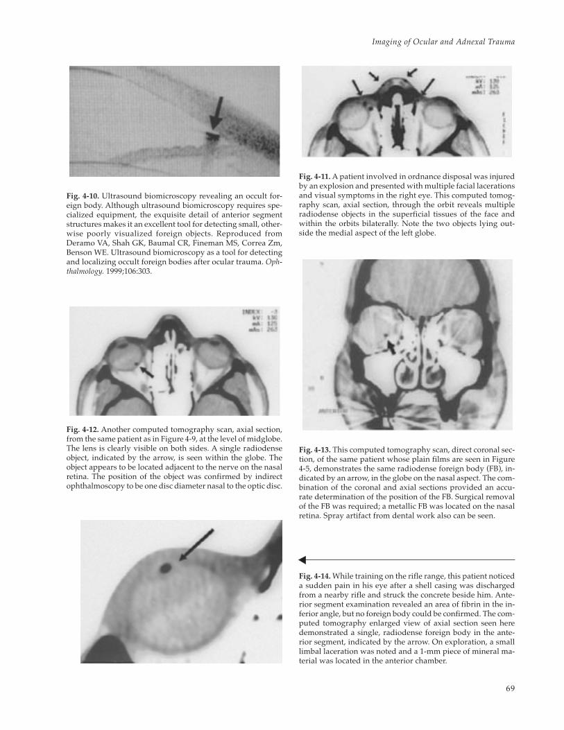
Fig. 4-14. While training on the rifle range, this patient noticeda sudden pain in his eye after a shell casing was dischargedfrom a nearby rifle and struck the concrete beside him. Ante-rior segment examination revealed an area of fibrin in the in-ferior angle, but no foreign body could be confirmed. The com-puted tomography enlarged view of axial section seen heredemonstrated a single, radiodense foreign body in the ante-rior segment, indicated by the arrow. On exploration, a smalllimbal laceration was noted and a 1-mm piece of mineral ma-terial was located in the anterior chamber.
Fig. 4-10. Ultrasound biomicroscopy revealing an occult for-eign body. Although ultrasound biomicroscopy requires spe-cialized equipment, the exquisite detail of anterior segmentstructures makes it an excellent tool for detecting small, other-wise poorly visualized foreign objects. Reproduced fromDeramo VA, Shah GK, Baumal CR, Fineman MS, Correa Zm,Benson WE. Ultrasound biomicroscopy as a tool for detectingand localizing occult foreign bodies after ocular trauma. Oph-thalmology. 1999;106:303.
Fig. 4-11. A patient involved in ordnance disposal was injuredby an explosion and presented with multiple facial lacerationsand visual symptoms in the right eye. This computed tomog-raphy scan, axial section, through the orbit reveals multipleradiodense objects in the superficial tissues of the face andwithin the orbits bilaterally. Note the two objects lying out-side the medial aspect of the left globe.
Fig. 4-12. Another computed tomography scan, axial section,from the same patient as in Figure 4-9, at the level of midglobe.The lens is clearly visible on both sides. A single radiodenseobject, indicated by the arrow, is seen within the globe. Theobject appears to be located adjacent to the nerve on the nasalretina. The position of the object was confirmed by indirectophthalmoscopy to be one disc diameter nasal to the optic disc.
Fig. 4-13. This computed tomography scan, direct coronal sec-tion, of the same patient whose plain films are seen in Figure4-5, demonstrates the same radiodense foreign body (FB), in-dicated by an arrow, in the globe on the nasal aspect. The com-bination of the coronal and axial sections provided an accu-rate determination of the position of the FB. Surgical removalof the FB was required; a metallic FB was located on the nasalretina. Spray artifact from dental work also can be seen.

70
Ophthalmic Care of the Combat Casualty
tecting FBs made of glass, metal, or mineral (Fig-ures 4-11 to 4-14). Lead, iron, solder, and chromiumhave relatively high attenuation coefficients; glassand stone have lower coefficients but still appearrelatively bright. Wood is almost isodense withwater and may be difficult to distinguish from thesurrounding soft tissue (Figure 4-15). The size andvolume of these objects are also factors in their de-tection.11,12 Steel objects with a volume as small as0.048 mm3 are detectable by CT scan, although steelobjects with a volume greater than 0.06 mm3 weredetected with a greater sensitivity in one experi-mental model.4
Helical or spiral CT scans present some benefitsover conventional CT scanning, and the ability todetect steel IOFBs seems equivalent to that of con-ventional CT.4 Scan times for the entire orbital vol-ume can be as fast as 18 seconds, which will mini-mize motion artifact and reduce radiation exposure.Furthermore, unlike conventional CT, high-resolu-tion coronal and sagittal images can be recon-structed from the axial scans, further limiting ra-diation exposure. Total exposure may be approxi-mately one fourth that required for a conventionalCT.5 Helical CT may be ideal for patients with lim-ited ability to cooperate or limited ability to posi-tion for conventional coronal CT scans.
Although excellent for the detection of high-den-
Fig. 4-15. A computed tomography scan, axial section,with enlargement of orbit (inset) of a patient in whom apencil had passed through the eyelid and into the orbitand brain. The relative radiopacity of the graphite isclearly seen, as well as the relative radiolucency of thesurrounding wood. This demonstrates how a woodenforeign body within the orbit may escape detection; amagnetic resonance imaging scan might well providemore information in cases like this. Computed tomogra-phy scan: Courtesy of Allen Thach, MD, Phoenix, Ariz.
sity materials, CT is poor for organic matter of com-parable size.13,14 MRI has been suggested15 as a reli-able method to detect nonmetallic FBs (glass, plas-tic, or mineral), but the detection of organic mattermay be much less reliable. A retrospective study16
concluded that identification of foreign material inthe orbit was possible in only about 50% of caseswith the use of CT and MRI.
The potential danger of MRI in the face of a fer-romagnetic FB in or outside the globe is clearly rec-ognized. An intraocular magnetic object can moveand grossly deform the globe17 or move through theorbit, potentially causing a blinding injury.18 A CTscan or plain film to exclude an iron or steel FB is aprerequisite for an MRI in the setting of an intraor-bital or intraocular FB.
Orbital Fractures
Fractures of the orbital bones can result from di-rect trauma to the facial bones or compression ofthe orbital soft tissues, resulting in a blowout frac-ture of the orbit. Plain films of the skull are still usedin emergency departments to screen for these frac-tures, and usually the telltale sign of an air–fluidlevel in the maxillary sinus prompts further radio-graphic evaluation. The definitive evaluation ofbony anatomy provided by the CT scan is an inte-gral part of the management of these injuries.
When an orbital fracture is suspected, a CT scanwith both axial and direct coronal sections shouldbe obtained. A section 1.5 mm to 3.0 mm in thick-ness is the usual protocol; very thin sections requirea longer scan time, straining the resources of theradiologist, and the extra information obtained maynot alter the management of the injury. The recentdevelopment of the helical CT may provide imag-ing options in patients with limited ability to coop-erate or position for direct coronal sections. Three-dimensional reconstruction, which requires themanipulation of digital images with special soft-ware, may also be useful in the management of com-plex orbital fractures. Although three-dimensionalimaging may not be useful to the general ophthal-mologist, an orbital surgeon faced with a difficultreconstruction may find the information valuable.When considering these more-complex imagingoptions, we should consult a radiologist early in theprocess to ensure that the desired result is obtainedmost efficiently.
Fractures of the orbital walls are most easily seenon coronal sections. Irregularities in the contoursof the medial or inferior orbital walls, as well as
71
Imaging of Ocular and Adnexal Trauma
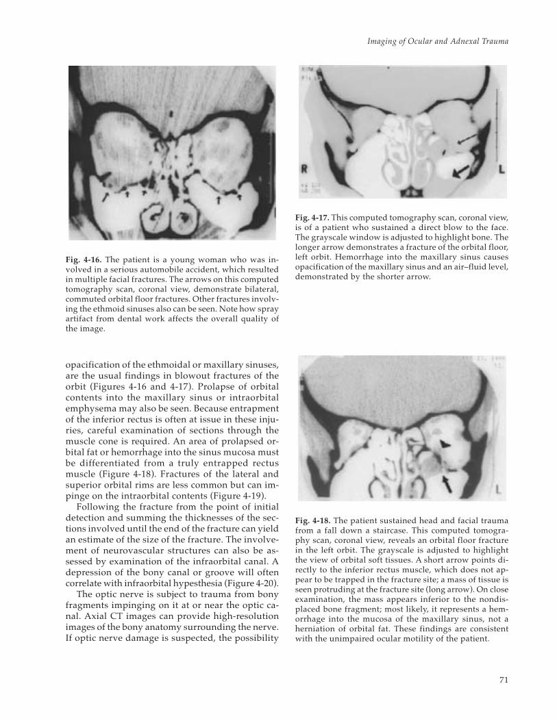
opacification of the ethmoidal or maxillary sinuses,are the usual findings in blowout fractures of theorbit (Figures 4-16 and 4-17). Prolapse of orbitalcontents into the maxillary sinus or intraorbitalemphysema may also be seen. Because entrapmentof the inferior rectus is often at issue in these inju-ries, careful examination of sections through themuscle cone is required. An area of prolapsed or-bital fat or hemorrhage into the sinus mucosa mustbe differentiated from a truly entrapped rectusmuscle (Figure 4-18). Fractures of the lateral andsuperior orbital rims are less common but can im-pinge on the intraorbital contents (Figure 4-19).
Following the fracture from the point of initialdetection and summing the thicknesses of the sec-tions involved until the end of the fracture can yieldan estimate of the size of the fracture. The involve-ment of neurovascular structures can also be as-sessed by examination of the infraorbital canal. Adepression of the bony canal or groove will oftencorrelate with infraorbital hypesthesia (Figure 4-20).
The optic nerve is subject to trauma from bonyfragments impinging on it at or near the optic ca-nal. Axial CT images can provide high-resolutionimages of the bony anatomy surrounding the nerve.If optic nerve damage is suspected, the possibility
Fig. 4-16. The patient is a young woman who was in-volved in a serious automobile accident, which resultedin multiple facial fractures. The arrows on this computedtomography scan, coronal view, demonstrate bilateral,commuted orbital floor fractures. Other fractures involv-ing the ethmoid sinuses also can be seen. Note how sprayartifact from dental work affects the overall quality ofthe image.
Fig. 4-17. This computed tomography scan, coronal view,is of a patient who sustained a direct blow to the face.The grayscale window is adjusted to highlight bone. Thelonger arrow demonstrates a fracture of the orbital floor,left orbit. Hemorrhage into the maxillary sinus causesopacification of the maxillary sinus and an air–fluid level,demonstrated by the shorter arrow.
Fig. 4-18. The patient sustained head and facial traumafrom a fall down a staircase. This computed tomogra-phy scan, coronal view, reveals an orbital floor fracturein the left orbit. The grayscale is adjusted to highlightthe view of orbital soft tissues. A short arrow points di-rectly to the inferior rectus muscle, which does not ap-pear to be trapped in the fracture site; a mass of tissue isseen protruding at the fracture site (long arrow). On closeexamination, the mass appears inferior to the nondis-placed bone fragment; most likely, it represents a hem-orrhage into the mucosa of the maxillary sinus, not aherniation of orbital fat. These findings are consistentwith the unimpaired ocular motility of the patient.

72
Ophthalmic Care of the Combat Casualty
Fig. 4-19. (a) This computed tomography scan, coronal section, demonstrates an orbital fracture involving the zygo-matic-frontal suture (arrow) with displacement of the bone fracture into the orbit. Associated soft-tissue swelling isalso visible on the lateral aspect of the skull. The patient was unable to elevate the globe. (b) This computed tomog-raphy scan, axial section, of the same patient demonstrates bony fragments (indicated by arrow) impinging on theglobe and interfering with supraduction. Computed tomography scans: Courtesy of Allen Thach, MD, Phoenix, Ariz.
Fig. 4-20. The patient sustained sports injury to the rightorbit 6 months before this computed tomography study,coronal view, was done. The long arrow indicates a frac-ture of the right orbital floor involving the infraorbitalcanal. The depression of the canal is consistent with theinfraorbital hypesthesia seen in these fractures. The ab-sence of an air–fluid level and a clear picture of the dis-placed sinus mucosa (arrowhead) suggest that the injuryis not acute.
Fig. 4-21. A computed tomography scan, axial view, of apatient with multiple skull fractures and no light per-ception following a motor vehicle accident. Fragmentsof the sphenoid bone (long arrows) can be seen imping-ing on the optic nerve (short arrow). The axial sectionthrough the optic canal can provide valuable informa-tion when a traumatic injury from a bone fragment issuspected.
a b
73
Imaging of Ocular and Adnexal Trauma
should be brought to the attention of the radiolo-gist before the study is obtained to ensure adequateimaging of the nerve and surrounding bone. Earlydetection of bone fragments impinging on the nervecan provide an opportunity for treatment by decom-pression, or at least early detection can provideuseful information to guide the treatment of thetraumatized eye and aid in the formulation of a re-alistic prognosis (Figure 4-21). In any case, whenvisual loss seems out of proportion to findings onophthalmoscopy, the possibility of traumatic opticneuropathy must be considered.
Blunt Ocular Trauma
The value of radiographic evaluation of the globewith CT is limited except in those incidents in whicha nebulous history cannot exclude the presence ofan FB. Although a CT scan may confirm a deformedglobe in cases of occult ruptures, the findings on aCT scan are unlikely to precipitate or prevent anexploration of a bluntly traumatized eye. An eyethat is suspected to have an occult rupture on clini-cal examination should be explored with or with-out supporting radiographic evidence.
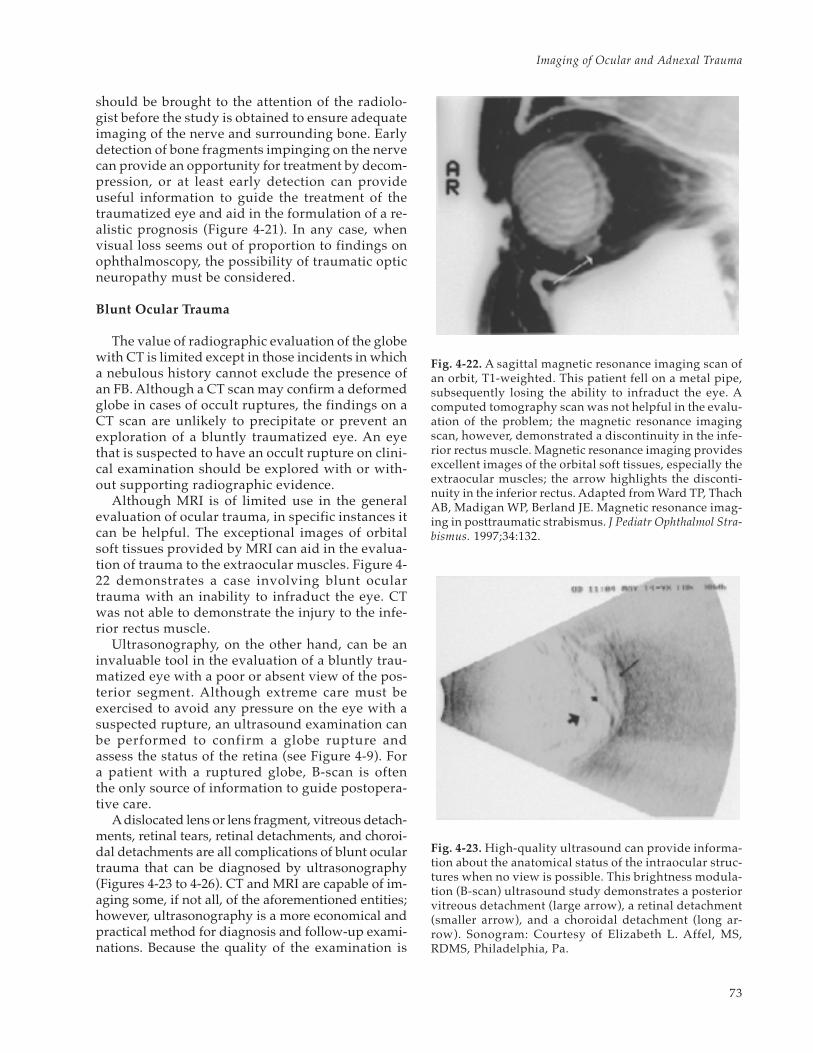
Although MRI is of limited use in the generalevaluation of ocular trauma, in specific instances itcan be helpful. The exceptional images of orbitalsoft tissues provided by MRI can aid in the evalua-tion of trauma to the extraocular muscles. Figure 4-22 demonstrates a case involving blunt oculartrauma with an inability to infraduct the eye. CTwas not able to demonstrate the injury to the infe-rior rectus muscle.
Ultrasonography, on the other hand, can be aninvaluable tool in the evaluation of a bluntly trau-matized eye with a poor or absent view of the pos-terior segment. Although extreme care must beexercised to avoid any pressure on the eye with asuspected rupture, an ultrasound examination canbe performed to confirm a globe rupture andassess the status of the retina (see Figure 4-9). Fora patient with a ruptured globe, B-scan is oftenthe only source of information to guide postopera-tive care.
A dislocated lens or lens fragment, vitreous detach-ments, retinal tears, retinal detachments, and choroi-dal detachments are all complications of blunt oculartrauma that can be diagnosed by ultrasonography(Figures 4-23 to 4-26). CT and MRI are capable of im-aging some, if not all, of the aforementioned entities;however, ultrasonography is a more economical andpractical method for diagnosis and follow-up exami-nations. Because the quality of the examination is
Fig. 4-23. High-quality ultrasound can provide informa-tion about the anatomical status of the intraocular struc-tures when no view is possible. This brightness modula-tion (B-scan) ultrasound study demonstrates a posteriorvitreous detachment (large arrow), a retinal detachment(smaller arrow), and a choroidal detachment (long ar-row). Sonogram: Courtesy of Elizabeth L. Affel, MS,RDMS, Philadelphia, Pa.
Fig. 4-22. A sagittal magnetic resonance imaging scan ofan orbit, T1-weighted. This patient fell on a metal pipe,subsequently losing the ability to infraduct the eye. Acomputed tomography scan was not helpful in the evalu-ation of the problem; the magnetic resonance imagingscan, however, demonstrated a discontinuity in the infe-rior rectus muscle. Magnetic resonance imaging providesexcellent images of the orbital soft tissues, especially theextraocular muscles; the arrow highlights the disconti-nuity in the inferior rectus. Adapted from Ward TP, ThachAB, Madigan WP, Berland JE. Magnetic resonance imag-ing in posttraumatic strabismus. J Pediatr Ophthalmol Stra-bismus. 1997;34:132.

74
Ophthalmic Care of the Combat Casualty
Fig. 4-24. In the hands of a skilled examiner, a high-qualityultrasound can demonstrate details usually only detectableon ophthalmoscopy. This brightness modulation (B-scan)ultrasound study demonstrates a retinal detachment, indi-cated by the small arrow, and the cause, a retinal tear dem-onstrated by the larger arrow. Sonogram: Courtesy of Eliza-beth L. Affel, MS, RDMS, Philadelphia, Pa.
Fig. 4-25. A lens dislocated into the posterior segment(arrow) can easily be detected by brightness modulation(B-scan) ultrasonography. Sonogram: Courtesy of Eliza-beth L. Affel, MS, RDMS, Philadelphia, Pa.
Fig. 4-26. (a) A brightness modulation (B-scan) ultra-sound study of a patient with a remote history of oculartrauma. The dislocated native lens can be seen restingon the surface of the retina. (b) An amplitude modula-tion (A-scan) ultrasound study of the same patient dem-onstrates a peak at the position of the anterior surface ofthe dislocated lens. (c) An A-scan ultrasound study of anormal eye, in which echoes are plotted against time,reflecting the distance of the target from the probe. Anabsence of echoes is noted through the vitreous cavityuntil a sharp peak generated by the surface of the retinais encountered. In the hands of most ophthalmologists,for the detection and analysis of foreign bodies, the use-fulness of A-scan ultrasonography is limited.
b
c
a

75
Imaging of Ocular and Adnexal Trauma
dependent on the skill of the examiner, a basic levelof competence with the ultrasound examination of
the eye should be the goal of every ophthalmolo-gist who manages traumatized eyes.
SUMMARY
Plain film radiography, CT, MRI, and ultrasonog-raphy are all methods used to image the ocular andadnexal structures in the evaluation of trauma. Al-though CT is the best and standard method of evalu-ating the orbital fractures and aids in the detectionof orbital and ocular FBs, both MRI and ultrasonog-
raphy play supporting roles. In instances of blunttrauma to the globe, however, the roles are reversed:ultrasonography becomes much more important asa diagnostic tool, and radiographic evaluation andMRI play minor roles in the detection and manage-ment of the ocular pathology.
REFERENCES
1. Weber AL. Imaging techniques and normal radiographic anatomy. In: Albert DM, ed. Principles and Practice ofOphthalmology. Vol 5. Philadelphia, Pa: WB Saunders Company; 1994: 3505–3510.
2. Moseley L. The orbit and eye. In: Sutton D, ed. A Textbook of Radiology and Imaging. Vol 2. London, England:Churchill Livingstone; 1993: 1287–1309.
3. Wiesen EJ, Miraldi F. Imaging principles in computed tomography. In: Haaga JR, ed. Computed Tomography andMagnetic Resonance Imaging of the Whole Body. Vol 1. St. Louis, Mo: Mosby; 1994: 3–25.
4. Chacko JG, Figueroa RE, Johnson MH, Marcus DM, Brooks SE. Detection and localization of steel intraocularforeign bodies using computed tomography: A comparison of helical and conventional axial scanning. Oph-thalmology. 1997;104:319–323.
5. Lakits A, Prokesch R, Scholda C, Bankier A, Weninger F, Imhof H. Multiplanar imaging in the preoperativeassessment of metallic intraocular foreign bodies: Helical computed tomography versus conventional com-puted tomography. Ophthalmology. 1998;105:1679–1685.
6. Berges O. Orbital ultrasonography: Principles and technique. In: Newton TH, ed. Radiology of the Eye and Orbit.New York, NY: Raven Press; 1990: 6.1–6.20.
7. Pavlin C, Harasiewicz K, Sherar M, Foster I F. Clinical use of ultrasound biomicroscopy. Ophthalmology.1991;98:287–295.
8. Pavlin C, Sherar M, Foster F. Subsurface ultrasound microscopic imaging of the intact eye. Ophthalmology.1990;97:244–250.
9. Kramer M, Hart L, Miller JW. Ultrasonography in the management of penetrating ocular trauma [review]. IntOphthalmol Clin. 1995 Winter;35(1):181–192.
10. Deramo VA, Shah GK, Baumal CR, Fineman MS, Correa ZM, Benson WE. Ultrasound biomicroscopy as a toolfor detecting and localizing occult foreign bodies after ocular trauma. Ophthalmology. 1999;106:301–305.
11. Gunenc U, Maden A, Kaynak S, Pirnar T. Magnetic resonance imaging and computed tomography in the detec-tion and localization of intraocular foreign bodies. Doe Ophthalmol. 1992;81:369–378.
12. Kadir S, Aronow S, Davis KR. The use of computerized tomography in the detection of intraorbital foreignbodies. Comput Tomogr. 1977;1:151–156.
13. Grove AS Jr. Computed tomography in the management of orbital trauma. Ophthalmology. 1982;89:433–440.
14. Zinreich SJ, Miller NR, Aguayo JB, Quinn C, Hadfield R, Rosenbaum A. Computed tomographic three-dimen-sional localization and compositional evaluation of intraocular and orbital foreign bodies. Arch Ophthalmol.1986;104:1477–1482.

76
Ophthalmic Care of the Combat Casualty
15. LoBue TD, Deutsch TA, Lobick J, Turner DA. Detection and localization of nonmetallic intraocular foreignbodies by magnetic resonance imaging. Arch Ophthalmol. 1988;106:260–261.
16 Nasr AM, Barret GH, Fleming JC, Al-Hussain HM, Karcioglu ZA. Penetrating orbital injury with organic for-eign bodies. Ophthalmology. 1999;106:523–532.
17. Williamson TH, Smith FW, Forrester JV. Magnetic resonance imaging of intraocular foreign bodies. Br JOphthalmol. 1989;73:555–558.
18. Kulshrestha M, Mission G. Magnetic resonance imaging and the dangers of orbital foreign bodies. Br J Ophthalmol.1995;79:1149.