chapter 5 short range aids to navigation dangers, or at other points where mariners can best use...
TRANSCRIPT
63
CHAPTER 5
SHORT RANGE AIDS TO NAVIGATION
DEFINING SHORT RANGE AIDS TO NAVIGATION
500. Terms And Definitions
The term “short range aids to navigation” encompasseslighted and unlighted beacons, ranges, leading lights,buoys, and their associated sound signals. Each short rangeaid to navigation, commonly referred to as a NAVAID, fitswithin a system designed to warn the mariner of dangersand direct him toward safe water. An aid’s function deter-mines its color, shape, light characteristic, and sound. Thischapter explains the U.S. Aids to Navigation System aswell as the international IALA Maritime Buoyage System.
The placement and maintenance of marine aids to nav-igation in U.S. waters is the responsibility of the UnitedStates Coast Guard. The Coast Guard maintains lighthous-
es, radiobeacons, racons, Loran C, sound signals, buoys,and daybeacons on the navigable waters of the UnitedStates, its territories, and possessions. Additionally, theCoast Guard exercises control over privately owned navi-gation aid systems.
A beaconis a stationary, visual navigation aid. Largelighthouses and small single-pile structures are both bea-cons. Lighted beacons are calledlights; unlighted beaconsaredaybeacons. All beacons exhibit adaymark of somesort. In the case of a lighthouse, the color and type of struc-ture are the daymarks. On small structures, these daymarks,consisting of colored geometric shapes calleddayboards,often have lateral significance. Conversely, the markingson lighthouses and towers convey no lateral significance.
FIXED LIGHTS
501. Major And Minor Lights
Lights vary from tall, high intensity coastal lights tobattery-powered lanterns on single wooden piles. Immov-able, highly visible, and accurately charted, fixed lightsprovide navigators with an excellent source for bearings.The structures are often distinctively colored to aid in iden-tification. See Figure 501a.
A major light is a high-intensity light exhibited froma fixed structure or a marine site. Major lights include pri-mary seacoast lights and secondary lights.Primaryseacoast lightsare those major lights established for mak-ing landfall from sea and coastwise passages from headlandto headland.Secondary lightsare those major lights estab-lished at harbor entrances and other locations where highintensity and reliability are required.
A minor light usually displays a light of low to mod-erate intensity. Minor lights are established in harbors,along channels, rivers, and in isolated locations. They usu-ally have numbering, coloring, and light and soundcharacteristics that are part of the lateral system of buoyage.
Lighthousesare placed where they will be of most use:on prominent headlands, at harbor and port entrances, onisolated dangers, or at other points where mariners can bestuse them to fix their position. The lighthouse’s principalpurpose is to support a light at a considerable height abovethe water, thereby increasing its geographic range. Supportequipment is often housed near the tower.
With few exceptions, all major lights are operated au-tomatically. There are also many automatic lights onsmaller structures maintained by the Coast Guard or otherattendants. Unmanned major lights may have emergencygenerators and automatic monitoring equipment to increasethe light’s reliability.
Light structures’ appearances vary. Lights in low-lyingareas usually are supported by tall towers; conversely, lightstructures on high cliffs may be relatively short. Howeverits support tower is constructed, almost all lights are simi-larly generated, focused, colored, and characterized.
Some major lights use modern rotating or flashinglights, but many older lights useFresnellenses. These lens-es consist of intricately patterned pieces of glass in a heavybrass framework. Modern Fresnel-type lenses are cast fromhigh-grade plastic; they are much smaller and lighter thantheir glass counterparts.
A buoyant beaconprovides nearly the positional ac-curacy of a light in a place where a buoy would normally beused. See Figure 501b. The buoyant beacon consists of aheavy sinker to which a pipe structure is tightly moored. Abuoyancy chamber near the surface supports the pipe. Thelight, radar reflector, and other devices are located atop thepipe above the surface of the water. The pipe with its buoy-ancy chamber tends to remain upright even in severeweather and heavy currents, providing a smaller watch cir-cle than a buoy. The buoyant beacon is most useful alongnarrow ship channels in relatively sheltered water.

64 SHORT RANGE AIDS TO NAVIGATION
502. Range Lights
Range lightsare light pairs that indicate a specific line ofposition when they are in line. The higher rear light is placedbehind the front light. When the mariner sees the lights verti-cally in line, he is on the range line. If the front light appearsleft of the rear light, the observer is to the right of the rangeline;if the front appears to the right of the rear, the observer is leftof the rangeline. Range lights are sometimes equipped withhigh intensity lights for daylight use. These are effective forlong channels in hazy conditions when dayboards might not beseen. The range light structures are usually also equipped withdayboards for ordinary daytime use. Some smaller ranges, pri-marily in the Intracoastal Waterway and other inland waters,have just the dayboards with no lights. See Figure 502.
To enhance the visibility of range lights, the CoastGuard has developed 15-foot long lighted tubes calledlightpipes. They are mounted vertically, and the mariner seesthem as vertical bars of light distinct from backgroundlighting. Installation of light pipes is proceeding on several
range markers throughout the country. The Coast Guard isalso experimenting with long range sodium lights for areasrequiring visibility greater than the light pipes can provide.
The output from a low pressure sodium light is almostentirely at one wavelength. This allows the use of an inex-pensive band-pass filter to make the light visible evenduring the daytime. This arrangement eliminates the needfor high intensity lights with their large power requirements.
Range lights are usually white, red, or green. They dis-play various characteristics differentiating them fromsurrounding lights.
A directional light is a single light that projects a highintensity, special characteristic beam in a given direction. Itis used in cases where a two-light range may not be practi-cable. Adirectional sector light is a directional light thatemits two or more colored beams. The beams have a pre-cisely oriented boundary between them. A normalapplication of a sector light would show three colored sec-tions: red, white, and green. The white sector wouldindicate that the vessel is on the channel centerline; the
Figure 501a. Typical offshore light station.
Figure 501b. Typical design for a buoyant beacon.

SHORT RANGE AIDS TO NAVIGATION 65
green sector would indicate that the vessel is off the channelcenterline in the direction of deep water; and the red sectorwould indicate that the vessel is off the centerline in the di-rection of shoal water.
503. Aeronautical Lights
Aeronautical lights may be the first lights observed atnight when approaching the coast. Those situated near thecoast and visible from sea are listed in theList of Lights.These lights are not listed in the Coast GuardLight List.They usually flash alternating white and green.
Aeronautical lights are sequenced geographically intheList of Lightsalong with marine navigation lights. How-ever, since they are not maintained for marine navigation,they are subject to changes of which maritime authoritiesmay not be informed. These changes will be published inNotice to Airmen but perhaps not inNotice To Mariners.
504. Bridge Lights
Red, green, and white lights mark bridges across naviga-ble waters of the United States. Red lights mark piers andother parts of the bridge. Red lights are also used on draw-bridges to show when they are in the closed position. Greenlights mark open drawbridges and mark the centerline of nav-igable channels through fixed bridges. The position will varyaccording to the type of structure. Navigational lights onbridges in the U.S. are prescribed by Coast Guard regulations.
Infrequently-used bridges may be unlighted. In foreignwaters, the type and method of lighting may be different fromthose normally found in the United States. Drawbridges whichmust be opened to allow passage operate upon sound and lightsignals given by the vessel and acknowledged by the bridge.These required signals are detailed in the Code of Federal Reg-
ulations and the applicable Coast Pilot. Certain bridges mayalso be equipped with sound signals and radar reflectors.
505. Shore Lights
Shore lights usually have a shore-based power supply.Lights on pilings, such as those found in the Intracoastal Wa-terway, are battery powered. Solar panels may be installed toenhance the light’s power supply. The lights consist of a pow-er source, a flasher to determine the characteristic, a lampchanger to replace burned-out lamps, and a focusing lens.
Various types of rotating lights are in use. They do nothave flashers but remain continuously lit while a lens or re-flector rotates around the horizon.
The whole light system is carefully engineered to pro-vide the maximum amount of light to the mariner for theleast power use. Specially designed filaments and specialgrades of materials are used in the light to withstand theharsh marine environment.
The flasher electronically determines the characteris-tic by selectively interrupting the light’s power supplyaccording to the chosen cycle.
The lamp changer consists of several sockets ar-ranged around a central hub. When the circuit is broken bya burned-out filament, a new lamp is rotated into position.Almost all lights have daylight switches which turn thelight off at sunrise and on at dusk.
The lens for small lights may be one of several types.The common ones in use are omni-directional lenses of155mm, 250mm, and 300mm. In addition, lights using par-abolic mirrors or focused-beam lenses are used in leadinglights and ranges. The lamp filaments must be carefullyaligned with the plane of the lens or mirror to provide themaximum output of light. The lens’ size is chosen accordingto the type of platform, power source, and lamp characteris-
Figure 502. Range lights.

66 SHORT RANGE AIDS TO NAVIGATION
tics. Additionally, environmental characteristics of thelocation are considered. Various types of light-condensingpanels, reflex reflectors, or colored sector panels may be in-
stalled inside the lens to provide the proper characteristic.A special heavy 200mm lantern is used in locations
where ice and breaking water are a hazard.
LIGHT CHARACTERISTICS
506. Characteristics
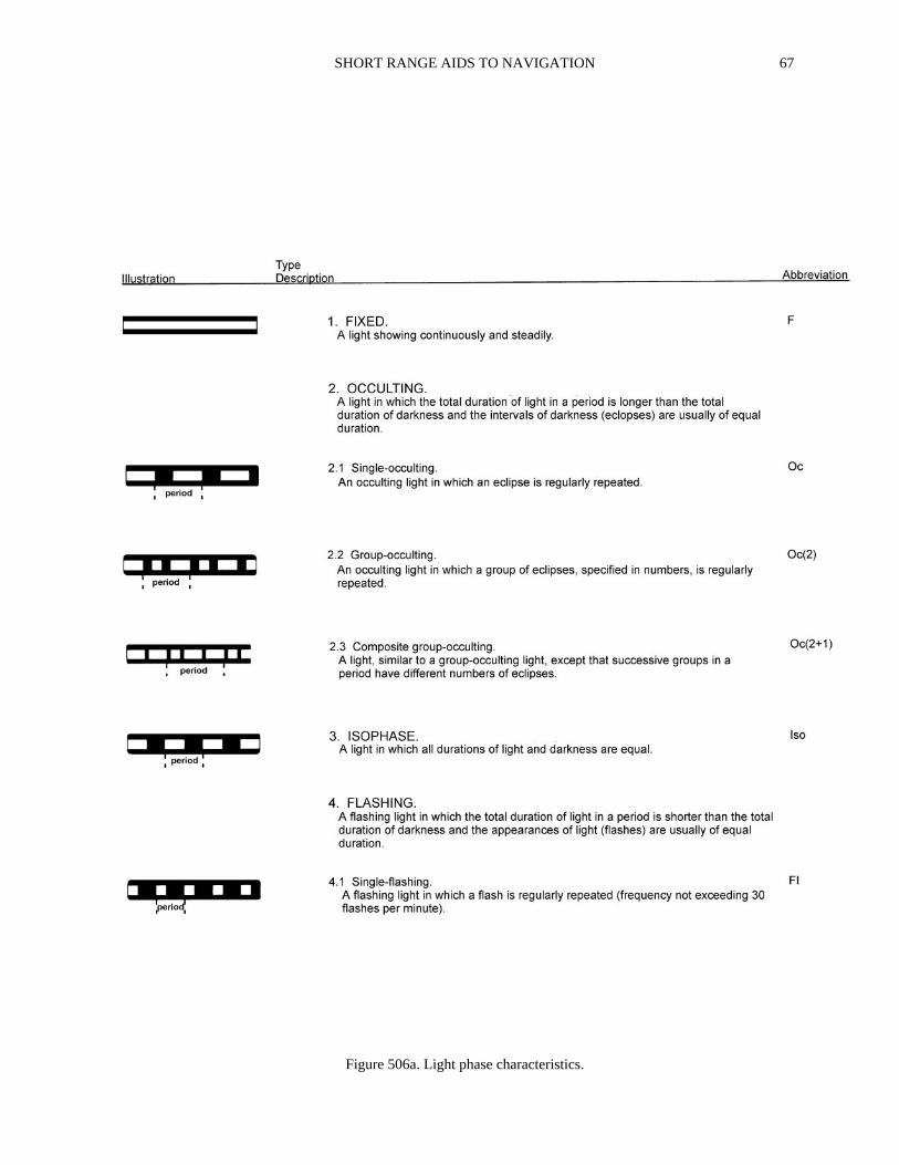
A light has distinctivecharacteristics which distin-guish it from other lights or convey specific information. Alight may show a distinctive sequence of light and dark in-tervals. Additionally, a light may display a distinctive coloror color sequence. In the Light Lists, the dark intervals arereferred to aseclipses. An occulting light is a light totallyeclipsed at regular intervals, the duration of light always be-ing greaterthan the duration of darkness. Aflashing lightis a light which flashes at regular intervals, the duration oflight always beinglessthan the duration of darkness. Anisophaselight flashes at regular intervals, the duration oflight beingequal to the duration of darkness.
Light phase characteristics (Figure 506a and Figure506b) are the distinctive sequences of light and dark inter-vals or sequences in the variations of the luminous intensityof a light. The light phase characteristics of lights whichchange color do not differ from those of lights which do notchange color. A light showing different colors alternately isdescribed as analternating light. The alternating charac-teristic may be used with other light phase characteristics.
Light-sensitive switches extinguish most lighted navi-gation aids during daylight hours. However, owing to thevarious sensitivity of the light switches, all lights do notcome on or go off at the same time. Mariners should ac-count for this when identifying aids to navigation duringtwilight periods when some lighted aids are on while othersare not.
507. Light Sectors
Sectors of colored glass or plastic are sometimesplaced in the lanterns of certain lights to indicate dangerouswaters. Lights so equipped show different colors when ob-served from different bearings. A sector changes the colorof a light, but not its characteristic, when viewed from cer-tain directions. For example, a four second flashing whitelight having a red sector will appear as a four second flash-ing red light when viewed from within the red sector.
Sectors may be only a few degrees in width or extendin a wide arc from deep water toward shore. Bearings refer-ring to sectors are expressed in degrees trueas observedfrom a vessel.
In most cases, areas covered by red sectors should beavoided. The nature of the danger can be determined fromthe chart. In some cases a narrow sector may mark the bestwater across a shoal, or a turning point in a channel.
Sectors generated by shadow-casting filters do nothave precise boundaries as directional sector lights do.
Therefore, the transition from one color to another is notabrupt. The colors change through an arc of uncertainty of2° or greater, depending on the optical design of the light.Therefore determining bearings by observing the colorchange is less accurate than obtaining a bearing with an az-imuth circle.
508. Factors Affecting Range And Characteristics
The condition of the atmosphere has a considerable effectupon a light’s range. Sometimes lights are obscured by fog,haze, dust, smoke, or precipitation. On the other hand, refrac-tion may cause a light to be seen farther than under ordinarycircumstances. A light of low intensity will be easily obscuredby unfavorable conditions of the atmosphere. For this reason,the intensity of a light should always be considered when look-ing for it in thick weather. Haze and distance may reduce theapparent duration of a light’s flash. In some conditions of theatmosphere, white lights may have a reddish hue. In clearweather green lights may have a more whitish hue.
Lights placed at great elevations are more frequentlyobscured by clouds, mist, and fog than those near sea level.In regions where ice conditions prevail, an unattendedlight’s lantern panes may become covered with ice or snowThis may reduce the light’s luminous range and change thelight’s observed color.
The distance from a lightcannotbe estimated by its ap-parent brightness. There are too many factors which canchange the perceived intensity. Also, a powerful, distantlight may sometimes be confused with a smaller, closer onewith similar characteristics. Every light sighted should becarefully evaluated to determine if it is the one expected.
The presence of bright shore lights may make it diffi-cult to distinguish navigational lights from backgroundlighting. Lights may also be obscured by various shore ob-structions, natural and man-made. The Coast Guardrequests mariners to report these cases to the nearest CoastGuard station.
A light’s loom is seen through haze or the reflectionfrom low-lying clouds when the light is beyond its geo-graphic range. Only the most powerful lights can generatea loom. The loom may sometimes be sufficiently defined toobtain a bearing. If not, an accurate bearing on a light be-yond geographic range may sometimes be obtained byascending to a higher level where the light can be seen, andnoting a star directly over the light. The bearing of the starcan then be obtained from the navigating bridge and thebearing to the light plotted indirectly.
At short distances, some of the brighter flashing lightsmay show a faint continuous light, or faint flashes, between
SHORT RANGE AIDS TO NAVIGATION 67
Figure 506a. Light phase characteristics.

68 SHORT RANGE AIDS TO NAVIGATION
Figure 506b. Light phase characteristics.

SHORT RANGE AIDS TO NAVIGATION 69
regular flashes. This is due to reflections of a rotating lenson panes of glass in the lighthouse.
If a light is not sighted within a reasonable time afterprediction, a dangerous situation may exist. Conversely, thelight may simply be obscured or extinguished. The ship’sposition should immediately be fixed by other means to de-termine any possibility of danger.
The apparent characteristic of a complex light maychange with the distance of the observer. For example, alight with a characteristic of fixed white and alternatingflashing white and red may initially show as a simple flash-ing white light. As the vessel draws nearer, the red flashwill become visible and the characteristic will apparentlybe alternating flashing white and red. Later, the fainterfixed white light will be seen between the flashes and thetrue characteristic of the light finally recognized as fixed
white, alternating flashing white and red (F W Al W R).This is because for a given candlepower, white is the mostvisible color, green less so, and red least of the three. Thisfact also accounts for the different ranges given in the LightLists for some multi-color sector lights. The same lamp hasdifferent ranges according to the color imparted by the sec-tor glass.
A light may beextinguisheddue to weather, batteryfailure, vandalism, or other causes. In the case of unattend-ed lights, this condition might not be immediatelycorrected. The mariner should report this condition to thenearest Coast Guard station. During periods of armed con-flict, certain lights may be deliberately extinguishedwithout notice.
Offshore light stations should always be left well offthe course whenever searoom permits.
BUOYS
509. Definitions And Types
Buoysare floating aids to navigation. They mark chan-nels, indicate shoals and obstructions, and warn the marinerof dangers. Buoys are used where fixed aids would be un-economical or impractical due to the depth of water. Bytheir color, shape, topmark, number, and light characteris-tics, buoys indicate to the mariner how to avoid hazards andstay in safe water. The federal buoyage system in the U.S.is maintained by the Coast Guard.
There are many different sizes and types of buoys de-signed to meet a wide range of environmental conditionsand user requirements. The size of a buoy is determined pri-marily by its location. In general, the smallest buoy whichwill stand up to local weather and current conditions ischosen.
There are five types of buoys maintained by the CoastGuard. They are:
1. Lateral marks.2. Isolated danger marks.3. Safe water marks.4. Special marks.5. Information/regulatory marks.
These conform in general to the specifications of theInternational Association of Lighthouse Authorities(IALA) buoyage system.
A lighted buoy is a floating hull with a tower on whicha light is mounted. Batteries for the light are in watertightpockets in the buoy hull or in watertight boxes mounted onthe buoy hull. To keep the buoy in an upright position, acounterweight is attached to the hull below the water sur-face. A radar reflector is built into the buoy tower.
The largest of the typical U.S. Coast Guard buoys canbe moored in up to 190 feet of water, limited by the weightof chain the hull can support. The focal plane of the light is
15 to 20 feet high. The designed nominal visual range is 3.8miles, and the radar range 4 miles. Actual conditions willcause these range figures to vary considerably.
The smallest buoys are designed for protected water.Some are made of plastic and weigh only 40 pounds. Spe-cially designed buoys are used for fast current, ice, andother environmental conditions.
A variety of special purpose buoys are owned by othergovernmental organizations. Examples of these organiza-tions include the Panama Canal Commission, the St.Lawrence Seaway Development Corporation, NOAA, andthe Department of Defense. These buoys are usually navi-gational marks or data collection buoys with traditionalround, boat-shaped, or discus-shaped hulls.
A special class of buoy, theOcean Data AcquisitionSystem (ODAS)buoy, is moored or floats free in offshore
Figure 509. Buoy showing counterweight.

70 SHORT RANGE AIDS TO NAVIGATION
waters. Positions are promulgated through radio warnings.These buoys are generally not large enough to cause dam-age in a collision, but should be given a wide berthregardless, as any loss would almost certainly result in theinterruption of valuable scientific experiments. They aregenerally bright orange or yellow in color, with verticalstripes on moored buoys and horizontal bands on free-float-ing ones, and have a strobe light for night visibility.
Even in clear weather, the danger of collision with abuoy exists. If struck head-on, a large buoy can inflict se-vere damage to a large ship; it can sink a smaller one.Reduced visibility or heavy background lighting can con-tribute to the problem. The Coast Guard sometimesreceives reports of buoys missing from station that were ac-tually run down and sunk. Tugboats and towboats towing orpushing barges are particularly dangerous to buoys becauseof poor over-the-bow visibility when pushing or yawingduring towing. The professional mariner must reportanycollision with a buoy to the nearest Coast Guard unit. Fail-ure to do so may cause the next vessel to miss the channelor hit the obstruction marked by the buoy; it can also leadto fines and legal liability.
Routine on-station buoy maintenance consists of in-specting the mooring, cleaning the hull and superstructure,replacing the batteries, flasher, and lamps, checking wiringand venting systems, and verifying the buoy’s exact posi-tion. Every few years, each buoy is replaced by a similar aidand returned to a Coast Guard maintenance facility forcomplete refurbishment.
The placement of a buoy depends on its purpose and itsposition on the chart. Most buoys are placed on charted posi-tion as accurately as conditions allow. However, if a buoy’spurpose is to mark a shoal and the shoal is found to be in a dif-ferent position than the chart shows, the buoy will be placed toproperly mark the shoal, and not on its charted position.
510. Lights On Buoys
Buoy light systems consist of abattery pack, aflasherwhich determines the characteristic, alamp changerwhichautomatically replaces burned-out bulbs, alensto focus thelight, and ahousing which supports the lens and protectsthe electrical equipment.
Thebatteries consist of 12-volt lead/acid type batter-ies electrically connected to provide sufficient power to runthe proper flash characteristic and lamp size. These batterypacks are contained in pockets in the buoy hull, accessiblethrough water-tight bolted hatches or externally mountedboxes. Careful calculations based on light characteristicsdetermine how much battery power to install.
The flasher determines the characteristic of the lamp.It is installed in the housing supporting the lens.
The lamp changer consists of several sockets ar-ranged around a central hub. A new lamp rotates intoposition if the active one burns out.
Under normal conditions, thelensesused on buoys are
155mm in diameter at the base. 200 mm lenses are usedwhere breaking waves or swells call for the larger lens.They are colored according to the charted characteristic ofthe buoy. As in shore lights, the lamp must be carefully fo-cused so that the filament is directly in line with the focalplane of the lens. This ensures that the majority of the lightproduced is focused in a 360° horizontal fan beam A buoylight has a relatively narrow vertical profile. Because thebuoy rocks in the sea, the focal plane may only be visiblefor fractions of a second at great ranges. A realistic rangefor sighting buoy lights is 4-6 miles in good visibility.
511. Sound Signals On Buoys
Lighted sound buoys have the same general configura-tion as lighted buoys but are equipped with either a bell,gong, whistle, or horn.Bellsandgongsare sounded by tap-pers hanging from the tower that swing as the buoys roll inthe sea. Bell buoys produce only one tone; gong buoys pro-duce several tones. The tone-producing device is mountedbetween the legs of the pillar or tower.
Whistle buoys make a loud moaning sound caused bythe rising and falling motions of the buoy in the sea. Asound buoy equipped with an electronichorn will producea pure tone at regular intervals regardless of the sea state.Unlighted sound buoys have the same general appearanceas lighted buoys, but their underwater shape is designed tomake them lively in all sea states.
512. Buoy Moorings
Buoys requiremoorings to hold them in position. Typ-ically the mooring consists ofchain and a large concrete orcast ironsinker. See Figure 512. Because buoys are sub-jected to waves, wind, and tides, the moorings must be
Figure 512. A sinker used to anchor a buoy.

SHORT RANGE AIDS TO NAVIGATION 71
deployed with chain lengths much greater than the waterdepth. The scope of chain will normally be about 3 timesthe water depth. The length of the mooring chain defines awatch circle within which the buoy can be expected toswing. It is for this reason that the charted buoy symbol hasa “position approximate” circle to indicate its charted posi-tion, whereas a light position is shown by a dot at the exactlocation. Actual watch circles do not necessarily coincidewith the “position approximate” circles which representthem.
Over several years, the chain gradually wears out andmust be replaced with new. The worn chain is often castinto the concrete of new sinkers.
513. Large Navigational Buoys
Large navigational buoysare moored in open waterat approaches to major seacoast ports. These 40-foot diam-eter buoys (Figure 513) show lights from heights of about
36 feet above the water. Emergency lights automaticallyenergize if the main light is extinguished. These buoys mayalso have a radiobeacon and sound signals. Their conditionis monitored by radio from shore.
514. Wreck Buoys
A wreck buoy usually cannot be placed directly overthe wreck it is intended to mark because the buoy tendermay not want to pass over a shallow wreck or risk foulingthe buoy mooring. For this reason, a wreck buoy is usuallyplaced as closely as possible on the seaward or channelwardside of a wreck. In some situations, two buoys may be usedto mark the wreck, one lying off each end. The wreck maylie directly between them or inshore of a line between them,depending on the local situation. TheLocal Notice To Mar-iners should be consulted concerning details of theplacement of wreck buoys on individual wrecks. Often itwill also give particulars of the wreck and what activitiesmay be in progress to clear it.
Figure 513. Large navigational buoy.
72 SHORT RANGE AIDS TO NAVIGATION
The charted position of a wreck buoy will usually beoffset from the actual geographic position so that the wreckand buoy symbols do not coincide. Only on the largest scalechart will the actual and charted positions of both wreck andbuoy be the same. Where they might overlap, it is the wrecksymbol which occupies the exact charted position and thebuoy symbol which is offset.
Wreck buoys are required to be placed by the owner ofthe wreck, but they may be placed by the Coast Guard if theowner is unable to comply with this requirement. In general,privately placed aids are not as reliable as Coast Guard aids.
Sunken wrecks are sometimes moved away from theirbuoys by storms, currents, freshets, or other causes. Just asshoals may shift away from the buoys placed to mark them,wrecks may shift away from wreck buoys.
515. Fallibility Of Buoys
Buoys cannot be relied on to maintain their charted po-sitions consistently. They are subject to a variety of hazardsincluding severe weather, collision, mooring casualties, andelectrical failure. Report any discrepancy noted in a buoy tothe U.S. Coast Guard.
The buoy symbol shown on charts indicates the ap-proximate position of the sinker which secures the buoy to
the seabed. The approximate position is used because ofpractical limitations in placing and keeping buoys andtheir sinkers in precise geographical locations. These lim-itations include prevailing atmospheric and seaconditions, the slope and type of material making up theseabed, the scope of the mooring chain, and the fact thatthe positions of the buoys and the sinkers are not undercontinuous surveillance. The position of the buoy shiftsaround the area shown by the chart symbol due to the forc-es of wind and current.
A buoy may not be in its charted position because ofchanges in the feature it marks. For example, a buoy meantto mark a shoal whose boundaries are shifting might fre-quently be moved to mark the shoal accurately. ALocalNotice To Marinerswill report the change, and aNotice ToMariners chart correction may also be written. In somesmall channels which change often, buoys are not chartedeven when considered permanent; local knowledge is ad-vised in such areas.
For these reasons, a mariner must not rely completelyupon the position or operation of buoys, but should navi-gate using bearings of charted features, structures, and aidsto navigation on shore. Further, a vessel attempting to passtoo close aboard a buoy risks a collision with the buoy orthe obstruction it marks.
BUOYAGE SYSTEMS
516. Lateral And Cardinal Systems
There are two major types of buoyage systems: thelateral systemand thecardinal system. The lateral sys-tem is best suited for well-defined channels. Thedescription of each buoy indicates the direction of dangerrelative to the course which is normally followed. In prin-ciple, the positions of marks in the lateral system aredetermined by thegeneral direction taken by the marinerwhen approaching port from seaward. These positionsmay also be determined with reference to the main streamof flood current. The United States Aids to NavigationSystem is a lateral system.
The cardinal system is best suited for coasts with nu-merous isolated rocks, shoals, and islands, and for dangersin the open sea. The characteristic of each buoy indicatesthe approximate true bearing of the danger it marks. Thus,an eastern quadrant buoy marks a danger which lies to thewest of the buoy. The following pages diagram the cardinaland lateral buoyage systems as found outside the UnitedStates.
517. The IALA Maritime Buoyage System
Although most of the major maritime nations haveused either the lateral or the cardinal system for many years,details such as the buoy shapes and colors have varied fromcountry to country. With the increase in maritime com-
merce between countries, the need for a uniform system ofbuoyage became apparent.
In 1889, an International Marine Conference held inWashington, D.C., recommended that in the lateral system,starboard hand buoys be painted red and port hand buoysblack. Unfortunately, when lights for buoys were intro-duced some years later, some European countries placedred lights on the black port hand buoys to conform with thered lights marking the port side of harbor entrances, whilein North America red lights were placed on red starboardhand buoys. In 1936, a League of Nations subcommitteerecommended a coloring system opposite to the 1889proposal.
The International Association of Lighthouse Au-thorities (IALA) is a non-governmental organizationwhich consists of representatives of the worldwide commu-nity of aids to navigation services to promote informationexchange and recommend improvements based on newtechnologies. In 1980, with the assistance of IMO and theIHO, the lighthouse authorities from 50 countries and rep-resentatives of 9 international organizations concerned withaids to navigation met and adopted theIALA MaritimeBuoyage System. They established two regions,Region AandRegion B, for the entire world. Region A roughly cor-responds to the 1936 League of Nations system, and RegionB to the older 1889 system.
Lateral marks differ between Regions A and B. Lateralmarks in Region A use red and green colors by day and night

SHORT RANGE AIDS TO NAVIGATION 73
to indicate port and starboard sides of channels, respectively.In Region B, these colors are reversed with red to starboardand green to port. In both systems, the conventional directionof buoyage is considered to bereturning from sea,hence thephrase “red right returning” in IALA region B.
518. Types Of Marks
The IALA Maritime Buoyage System applies to allfixed and floating marks, other than lighthouses, sectorlights, leading lights and daymarks, lightships and largenavigational buoys, and indicates:
1. The side and center-lines of navigable channels.2. Natural dangers, wrecks, and other obstructions.3. Regulated navigation areas.4. Other important features.
Most lighted and unlighted beacons other than leadingmarks are included in the system. In general, beacon top-marks will have the same shape and colors as those used onbuoys. The system provides five types of marks which maybe used in any combination:
1. Lateral marks indicate port and starboard sides ofchannels.
2. Cardinal marks, named according to the four pointsof the compass, indicate that the navigable waterlies to the named side of the mark.
3. Isolated danger marks erected on, or moored direct-ly on or over, dangers of limited extent.
4. Safe water marks, such as midchannel buoys.5. Special marks, the purpose of which is apparent
from reference to the chart or other nauticaldocuments.
Characteristics Of Marks
The significance of a mark depends on one or morefeatures:
1. By day—color, shape, and topmark.2. By night—light color and phase characteristics.
Colors Of Marks
The colors red and green are reserved for lateral marks,and yellow for special marks. The other types of markshave black and yellow or black and red horizontal bands, orred and white vertical stripes.
Shapes Of Marks
There are five basic buoy shapes:1. Can.2. Cone.
3. Sphere.4. Pillar.5. Spar.
In the case of can, conical, and spherical, the shapeshave lateral significance because the shape indicates thecorrect side to pass. With pillar and spar buoys, the shapehas no special significance.
The term “pillar” is used to describe any buoy which issmaller than a “large navigation buoy (LNB)” and which hasa tall, central structure on a broad base; it includes beaconbuoys, high focal plane buoys, and others (except spar buoys)whose body shape does not indicate the correct side to pass.
Topmarks
The IALA System makes use ofcan, conical, spheri-cal, andX-shapedtopmarks only. Topmarks on pillar andspar buoys are particularly important and will be usedwherever practicable, but ice or other severe conditionsmay occasionally prevent their use.
Colors Of Lights
Where marks are lighted, red and green lights are re-served for lateral marks, and yellow for special marks. Theother types of marks have a white light, distinguished onefrom another by phase characteristic.
Phase Characteristics Of Lights
Red and green lights may have any phase characteris-tic, as the color alone is sufficient to show on which sidethey should be passed. Special marks, when lighted, have ayellow light with any phase characteristic not reserved forwhite lights of the system. The other types of marks haveclearly specified phase characteristics of white light: vari-ous quick-flashing phase characteristics for cardinal marks,group flashing (2) for isolated danger marks, and relativelylong periods of light for safe water marks.
Some shore lights specifically excluded from the IALASystem may coincidentally have characteristics correspond-ing to those approved for use with the new marks. Care isneeded to ensure that such lights are not misinterpreted.
519. IALA Lateral Marks
Lateral marks are generally used for well-definedchannels; they indicate the port and starboard hand sides ofthe route to be followed, and are used in conjunction with aconventional direction of buoyage.
This direction is defined in one of two ways:
1. Local direction of buoyage is the direction takenby the mariner when approaching a harbor, river es-tuary, or other waterway from seaward.

74 SHORT RANGE AIDS TO NAVIGATION
2. General direction of buoyage is determined bythe buoyage authorities, following a clockwise di-rection around continental land-masses, given insailing directions, and, if necessary, indicated oncharts by a large open arrow symbol.
In some places, particularly straits open at both ends,the local direction of buoyage may be overridden by thegeneral direction.
Along the coasts of the United States, the characteris-tics assume that proceeding “from seaward” constitutes aclockwise direction: a southerly direction along the Atlanticcoast, a westerly direction along the Gulf of Mexico coast,and a northerly direction along the Pacific coast. On theGreat Lakes, a westerly and northerly direction is taken asbeing “from seaward” (except on Lake Michigan, where asoutherly direction is used). On the Mississippi and OhioRivers and their tributaries, the characteristics of aids tonavigation are determined as proceeding from sea towardthe head of navigation. On the Intracoastal Waterway, pro-ceeding in a generally southerly direction along the Atlanticcoast, and in a generally westerly direction along the gulfcoast, is considered as proceeding “from seaward.”
520. IALA Cardinal Marks
A cardinal mark is used in conjunction with the com-pass to indicate where the mariner may find the bestnavigable water. It is placed in one of the four quadrants(north, east, south, and west), bounded by the true bearingsNW-NE, NE-SE, SE-SW, and SW-NW, taken from thepoint of interest. A cardinal mark takes its name from thequadrantin which it is placed.
The mariner is safe if he passes north of a north mark, eastof an east mark, south of a south mark, and west of a west mark.
A cardinal mark may be used to:
1. Indicate that the deepest water in an area is on thenamed side of the mark.
2. Indicate the safe side on which to pass a danger.3. Emphasize a feature in a channel, such as a bend,
junction, bifurcation, or end of a shoal.
Topmarks
Black double-cone topmarks are the most importantfeature, by day, of cardinal marks. The cones are verticallyplaced, one over the other. The arrangement of the cones isvery logical: North is two cones with their points up (as in“north-up”). South is two cones, points down. East is twocones with bases together, and west is two cones withpoints together, which gives a wineglass shape. “West is aWineglass” is a memory aid.
Cardinal marks carry topmarks whenever practicable,with the cones as large as possible and clearly separated.
Colors
Black and yellow horizontal bands are used to color acardinal mark. The position of the black band, or bands, isrelated to the points of the black topmarks.
Shape
The shape of a cardinal mark is not significant, butbuoys must be pillars or spars.
Lights
When lighted, a cardinal mark exhibits a white light; itscharacteristics are based on a group of quick or very quickflashes which distinguish it as a cardinal mark and indicate itsquadrant. The distinguishing quick or very quick flashes are:
North—UninterruptedEast—three flashes in a groupSouth—six flashes in a group followed by a long flashWest—nine flashes in a group
As a memory aid, the number of flashes in each groupcan be associated with a clock face as follows:
(3 o’clock—E, 6 o’clock—S, and 9 o’clock—W).
The long flash (of not less than 2 seconds duration),immediately following the group of flashes of a south car-dinal mark, is to ensure that its six flashes cannot bemistaken for three or nine.
The periods of the east, south, and west lights are, re-spectively, 10, 15, and 15 seconds if quick flashing; and 5,10, and 10 seconds if very quick flashing.
Quick flashing lights flash at a rate between 50 and 79flashes per minute, usually either 50 or 60. Very quickflashing lights flash at a rate between 80 and 159 flashes perminute, usually either 100 or 120.
It is necessary to have a choice of quick flashing orvery quick flashing lights in order to avoid confusion if, forexample, two north buoys are placed near enough to eachother for one to be mistaken for the other.
521. IALA Isolated Danger Marks
An isolated danger mark is erected on, or moored onor above, an isolated danger of limited extent which hasnavigable water all around it. The extent of the surroundingnavigable water is immaterial; such a mark can, for exam-ple, indicate either a shoal which is well offshore or an isletseparated by a narrow channel from the coast.
N Points up Black above yellow.S Points down Black below yellow.W Points together Black, yellow above and below.E Points apart Yellow, black above and below.

SHORT RANGE AIDS TO NAVIGATION 75
Position
On a chart, the position of a danger is the center of thesymbol or sounding indicating that danger; an isolated dan-ger buoy may therefore be slightly displaced from itsgeographic position to avoid overprinting the two symbols.The smaller the scale, the greater this offset will be. At verylarge scales the symbol may be correctly charted.
Topmark
A black double-sphere topmark is, by day, the most im-portant feature of an isolated danger mark. Wheneverpracticable, this topmark will be carried with the spheres aslarge as possible, disposed vertically, and clearly separated.
Color
Black with one or more red horizontal bands are thecolors used for isolated danger marks.
Shape
The shape of an isolated danger mark is not significant,but a buoy will be a pillar or a spar.
Light
When lighted, a white flashing light showing a groupof two flashes is used to denote an isolated danger mark. Asa memory aid, associate two flashes with two balls in thetopmark.
522. IALA Safe Water Marks
A safe water mark is used to indicate that there is nav-igable water all around the mark. Such a mark may be usedas a center line, mid-channel, or landfall buoy.
Color
Red and white vertical stripes are used for safe watermarks, and distinguish them from the black-banded, dan-ger-marking marks.
Shape
Spherical, pillar, or spar buoys may be used as safe watermarks.
Topmark
A single red spherical topmark will be carried, when-ever practicable, by a pillar or spar buoy used as a safewater mark.
Lights
When lighted, safe water marks exhibit a white light.This light can be occulting, isophase, a single long flash, orMorse “A.” If a long flash (i.e. a flash of not less than 2 sec-onds) is used, the period of the light will be 10 seconds. Asa memory aid, remember a single flash and a single spheretopmark.
523. IALA Special Marks
A special markmay be used to indicate a special areaor feature which is apparent by referring to a chart, sailingdirections, or notices to mariners. Uses include:
1. Ocean Data Acquisition System (ODAS) buoys.2. Traffic separation marks.3. Spoil ground marks.4. Military exercise zone marks.5. Cable or pipeline marks, including outfall pipes.6. Recreation zone marks.
Another function of a special mark is to define a channelwithin a channel. For example, a channel for deep draft vesselsin a wide estuary, where the limits of the channel for normalnavigation are marked by red and green lateral buoys, mayhave its boundaries or centerline marked by yellow buoys ofthe appropriate lateral shapes.
Color
Yellow is the color used for special marks.
Shape
The shape of a special mark is optional, but must notconflict with that used for a lateral or a safe water mark. Forexample, an outfall buoy on the port hand side of a channelcould be can-shaped but not conical.
Topmark
When a topmark is carried it takes the form of a singleyellow X.
Lights
When a light is exhibited it is yellow. It may show anyphase characteristic except those used for the white lights ofcardinal, isolated danger, and safe water marks, In the caseof ODAS buoys, the phase characteristic used is group-flashing with a group of five flashes every 20 seconds.
524. IALA New Dangers
A newly discovered hazard to navigation not yet shown

76 SHORT RANGE AIDS TO NAVIGATION
on charts, included in sailing directions, or announced by aNotice To Marinersis termed anew danger. The term cov-ers naturally occurring and man-made obstructions.
Marking
A new danger is marked by one or more cardinal or lat-eral marks in accordance with the IALA system rules. If thedanger is especially grave, at least one of the marks will beduplicated as soon as practicable by an identical mark untilthe danger has been sufficiently identified.
Lights
If a lighted mark is used for a new danger, it must ex-hibit a quick flashing or very quick flashing light. If acardinal mark is used, it must exhibit a white light; if a lat-eral mark, a red or green light.
Racons
The duplicate mark may carry a Racon, Morse coded D,showing a signal length of 1 nautical mile on a radar display.
525. Chart Symbols And Abbreviations
Spar buoys and spindle buoys are represented by the samesymbol; it is slanted to distinguish them from upright beaconsymbols. The abbreviated description of the color of a buoy isgiven under the symbol. Where a buoy is colored in bands, thecolors are indicated in sequence from the top. If the sequence ofthe bands is not known, or if the buoy is striped, the colors areindicated with the darker color first.
Topmarks
Topmark symbols are solid black except when the top-mark is red.
Lights
The period of the light of a cardinal mark is determinedby its quadrant and its flash characteristic (either quick-flashing or a very quick-flashing). The light’s period is lessimportant than its phase characteristic. Where space oncharts is limited, the period may be omitted.
Light flares
Magenta light-flares are normally slanted and inserted withtheir points adjacent to the position circles at the base of the sym-bols so the flare symbols do not obscure the topmark symbols.
Radar Reflectors
Radar reflectors are not affected by the IALA buoyage
rules. They are not charted for several reasons. It can be as-sumed that most major buoys are fitted with radarreflectors. It is also necessary to reduce the size and com-plexity of buoy symbols and associated legends. Finally, itis understood that, in the case of cardinal buoys, buoyageauthorities site the reflector so that it cannot be mistaken fora topmark. For these reasons, radar reflectors are not chart-ed under IALA rules.
The symbols and abbreviations of the IALA MaritimeBuoyage System may be found in U.S.. Chart No. 1, Nauti-cal Chart Symbols and Abbreviations, and in foreignequivalents.
526. Description Of The U.S. Aids to Navigation System
In the United States, the U.S. Coast Guard has incorpo-rated the major features of the IALA system with the existinginfrastructure of buoys and lights as explained below.
Colors
Under this system, green buoys mark a channel’s portside and obstructions which must be passed by keeping thebuoy on the port hand. Red buoys mark a channel’s star-board side and obstructions which must be passed bykeeping the buoy on the starboard hand.
Red and green horizontally bandedpreferred channelbuoys mark junctions or bifurcations in a channel or ob-structions which may be passed on either side. If thetopmost band is green, the preferred channel will be fol-lowed by keeping the buoy on the port hand. If the topmostband is red, the preferred channel will be followed by keep-ing the buoy on the starboard hand.
Red and white vertically striped safe water buoys marka fairway or mid-channel.
Reflective material is placed on buoys to assist in their de-tection at night with a searchlight. The color of the reflectivematerial agrees with the buoy color. Red or green reflective ma-terial may be placed on preferred channel (junction) buoys; redif topmost band is red or green if the topmost band is green.White reflective material is used on safe water buoys. Specialpurpose buoys display yellow reflective material. Warning orregulatory buoys display orange reflective horizontal bands anda warning symbol. Intracoastal Waterway buoys display a yel-low reflective square, triangle, or horizontal strip along with thereflective material coincident with the buoy’s function.
Shapes
Certain unlighted buoys are differentiated by shape. Redbuoys and red and green horizontally banded buoys with thetopmost band red are cone-shaped buoys callednuns. Greenbuoys and green and red horizontally banded buoys with thetopmost band green are cylinder-shaped buoys calledcans.
Unlighted red and white vertically striped buoys may bepillar shaped or spherical. Lighted buoys, sound buoys, and spar

SHORT RANGE AIDS TO NAVIGATION 77
buoys are not differentiated by shape to indicate the side onwhich they should be passed. Their purpose is indicated not byshape but by the color, number, or light characteristics.
Numbers
All solid colored buoys are numbered, red buoys bear-ing even numbers and green buoys bearing odd numbers.(Note that this same rule applies in IALA System A also.)The numbers increase from seaward upstream or towardland. No other colored buoys are numbered; however, anybuoy may have a letter for identification.
Light colors
Red lights are used only on red buoys or red and green hor-izontally banded buoys with the topmost band red. Green lightsare used only on the green buoys or green and red horizontallybanded buoys with the topmost band green. White lights areused on both “safe water” aids showing a Morse A characteristicand on Information and Regulatory aids.
Light Characteristics
Lights on red buoys or green buoys, if not occultingor isophase, will generally be regularly flashing (Fl). Forordinary purposes, the frequency of flashes will be notmore than 50 flashes per minute. Lights with a distinctcautionary significance, such as at sharp turns or mark-ing dangerous obstructions, will flash not less than 50
flashes but not more than 80 flashes per minute (quickflashing, Q). Lights on preferred channel buoys willshow a series of grouped flashes with successive groupsin a period having different number of flashes—compos-ite group flashing (or a quick light in which the sequenceof flashes is interrupted by regularly repeated eclipses ofconstant and long duration). Lights on safe water buoyswill always show a white Morse Code “A” (Short-Long)flash recurring at the rate of approximately eight timesper minute.
Daylight Controls
Lighted buoys have a special device to energize thelight when darkness falls and to de-energize the light whenday breaks. These devices are not of equal sensitivity;therefore all lights do not come on or go off at the sametime. Mariners should ensure correct identification of aidsduring twilight periods when some light aids to navigationare on while others are not.
Special Purpose Buoys
Buoys for special purposes are colored yellow. Whitebuoys with orange bands are for information or regulatorypurposes. The shape of special purpose buoys has no signif-icance. They are not numbered, but they may be lettered. Iflighted, special purpose buoys display a yellow light usual-ly with fixed or slow flash characteristics. Information andregulatory buoys, if lighted, display white lights.
BEACONS
527. Definition And Description
Beaconsare fixed aids to navigation placed on shoreor on pilings in relatively shallow water. If unlighted, thebeacon is referred to as adaybeacon. A daybeacon isidentified by its color and the color, shape, and number ofits dayboard. The simplest form of daybeacon consists ofa single pile with a dayboard affixed at or near its top. SeeFigure 527. Daybeacons may be used to form an unlightedrange.
Dayboards identify aids to navigation against daylightbackgrounds. The size of the dayboard required to make theaid conspicuous depends upon the aid’s intended range.
Most dayboards also display numbers or letters for iden-tification. The numbers, letters, and borders of most dayboardshave reflective tape to make them visible at night.
The detection, recognition, and identification distancesvary widely for any particular dayboard. They depend uponthe luminance of the dayboard, the sun’s position, and thelocal visibility conditions. Figure 527. Daybeacon.

78 SHORT RANGE AIDS TO NAVIGATION
SOUND SIGNALS
528. Types Of Sound Signals
Most lighthouses and offshore light platforms, as wellas some minor light structures and buoys, are equipped withsound-producing devices to help the mariner in periods oflow visibility. Charts and Light Lists contain the informa-tion required for positive identification. Buoys fitted withbells, gongs, or whistles actuated by wave motion may pro-duce no sound when the sea is calm. Sound signals are notdesigned to identify the buoy or beacon for navigation pur-poses. Rather, they allow the mariner to pass clear of thebuoy or beacon during low visibility.
Sound signals vary. The navigator must use theLight List to determine the exact length of each blast andsilent interval. The various types of sound signals alsodiffer in tone, facilitating recognition of the respectivestations.
Diaphonesproduce sound with a slotted piston movedback and forth by compressed air. Blasts may consist of ahigh and low tone. These alternate-pitch signals are called“two-tone.” Diaphones are not used by the Coast Guard, butthe mariner may find them on some private navigation aids.
Horns produce sound by means of a disc diaphragmoperated pneumatically or electrically. Duplex or triplexhorn units of differing pitch produce a chime signal.
Sirens produce sound with either a disc or a cup-shaped rotor actuated electrically or pneumatically. Sirensare not used on U.S. navigation aids.
Whistles use compressed air emitted through a cir-cumferential slot into a cylindrical bell chamber.
Bellsand gongs are sounded with a mechanically oper-ated hammer.
529. Limitations Of Sound Signals
As aids to navigation, sound signals have serious limi-tations because sound travels through the air in anunpredictable manner.
It has been clearly established that:
1. Sound signals are heard at greatly varying distanc-es and that the distance at which a sound signal canbe heard may vary with the bearing and timing ofthe signal.
2. Under certain atmospheric conditions, when asound signal has a combination high and low tone,it is not unusual for one of the tones to be inaudible.In the case of sirens, which produce a varying tone,portions of the signal may not be heard.
3. When the sound is screened by an obstruction,there are areas where it is inaudible.
4. Operators may not activate a remotely controlledsound aid for a condition unobserved from the con-trolling station.
5. Some sound signals cannot be immediately started.6. The status of the vessel’s engines and the location
of the observer both affect the effective range of theaid.
These considerations justify the utmost caution whennavigating near land in a fog. A navigator can never relyon sound signals alone; he should continuously man boththe radar and fathometer. He should place lookouts in po-sitions where the noises in the ship are least likely tointerfere with hearing a sound signal. The aid upon whicha sound signal rests is usually a good radar target, but col-lision with the aid or the danger it marks is always apossibility.
Emergency signals are sounded at some of the light andfog signal stations when the main and stand-by sound sig-nals are inoperative. Some of these emergency soundsignals are of a different type and characteristic than themain sound signal. The characteristics of the emergencysound signals are listed in the Light List.
The mariner should never assume:
1. That he is out of ordinary hearing distance because hefails to hear the sound signal.
2. That because he hears a sound signal faintly, he is farfrom it.
3. That because he hears it clearly, he is near it.4. That the distance from and the intensity of a sound on
any one occasion is a guide for any future occasion.5. That the sound signal is not sounding because he does
not hear it, even when in close proximity.6. That the sound signal is in the direction the sound ap-
pears to come from.
MISCELLANEOUS U.S. SYSTEMS
530. Intracoastal Waterway Aids To Navigation
The Intracoastal Waterway (ICW) runs parallel to theAtlantic and Gulf of Mexico coasts from Manasquan Inlet onthe New Jersey shore to the Texas/Mexican border. It follows
rivers, sloughs, estuaries, tidal channels, and other naturalwaterways, connected with dredged channels where neces-sary. Some of the aids marking these waters are marked withyellow; otherwise, the marking of buoys and beacons followsthe same system as that in other U.S. waterways.

SHORT RANGE AIDS TO NAVIGATION 79
Yellow symbols indicate that an aid marks the Intrac-oastal Waterway. Yellow triangles indicate starboard handaids, and yellow squares indicate port hand aids when fol-lowing the ICW’s conventional direction of buoyage. Non-lateral aids such as safe water, isolated danger, and frontrange boards are marked with a horizontal yellow band.Rear range boards do not display the yellow band. At ajunction with a federally-maintained waterway, the pre-ferred channel mark will display a yellow triangle or squareas appropriate. Junctions between the ICW and privatelymaintained waterways are not marked with preferred chan-nel buoys.
531. Western Rivers System
Aids to navigation on the Mississippi River and its trib-utaries above Baton Rouge generally conform to the lateralsystem of buoyage in use in the rest of the U.S. The follow-ing differences are significant:
1. Buoys are not numbered.2. The numbers on lights and daybeacons do not have
lateral significance; they indicate the mileage froma designated point, normally the river mouth.
3. Flashing lights on the left side proceeding upstreamshow single green or white flashes while those onthe right side show group flashing red or whiteflashes.
4. Diamond shaped crossing daymarks are used to in-dicate where the channel crosses from one side ofthe river to the other.
532. The Uniform State Waterway Marking System(USWMS)
This system was developed jointly by the U.S. CoastGuard and state boating administrators to assist the smallcraft operator in those state waters marked by participatingstates. TheUSWMS consists of two categories of aids tonavigation. The first is a system of aids to navigation, gen-erally compatible with the Federal lateral system ofbuoyage, supplementing the federal system in state waters.The other is a system of regulatory markers to warn smallcraft operator of dangers or to provide general information.
On a well-defined channel, red and black buoys are estab-lished in pairs calledgates; the channel lies between the buoys.The buoy which marks the left side of the channel viewedlooking upstream or toward the head of navigation is black; thebuoy which marks the right side of the channel is red.
In an irregularly-defined channel, buoys may be stag-gered on alternate sides of the channel, but they are spacedat sufficiently close intervals to mark clearly the channel ly-ing between them.
When there is no well-defined channel or when a bodyof water is obstructed by objects whose nature or location issuch that the obstruction can be approached by a vessel
from more than one direction, aids to navigation havingcardinal significance may be used. The aids conforming tothe cardinal system consist of three distinctly coloredbuoys.
1. A white buoy with a red top must be passed to thesouth or west of the buoy.
2. A white buoy with a black top must be passed to thenorth or east of the buoy.
3. A buoy showing alternate vertical red and whitestripes indicates that an obstruction to navigationextends from the nearest shore to the buoy and thathe must not pass between the buoy and the nearestshore.
The shape of buoys has no significance under theUSWMS.
Regulatory buoys are colored white with orange hor-izontal bands completely around them. One band is at thetop of the buoy and a second band just above the water-line of the buoy so that both orange bands are clearlyvisible.
Geometric shapes colored orange are placed on thewhite portion of the buoy body. The authorized geometricshapes and meanings associated with them are as follows:
1. A vertical open faced diamond shape meansdanger.
2. A vertical open faced diamond shape with a crosscentered in the diamond means that vessels are ex-cluded from the marked area.
3. A circular shape means that vessels in the markedarea are subject to certain operating restrictions.
4. A square or rectangular shape indicates that direc-tions or information is written inside the shape.
Regulatory markers consist of square and rectangularshaped signs displayed from fixed structures. Each sign iswhite with an orange border. Geometric shapes with thesame meanings as those displayed on buoys are centered onthe sign boards. The geometric shape displayed on a regu-latory marker tells the mariner if he should stay well clearof the marker or if he may approach the marker in order toread directions.
533. Private Aids To Navigation
A private navigation aid is any aid established andmaintained by entities other than the Coast Guard.
The Coast Guard must approve the placement of pri-vate navigation aids. In addition, the District Engineer, U.S.Army Corps of Engineers, must approve the placement ofany structure, including aids to navigation, in the navigablewaters of the U.S.
Private aids to navigation are similar to the aids estab-lished and maintained by the U.S. Coast Guard; they are

80 SHORT RANGE AIDS TO NAVIGATION
specially designated on the chart and in the Light List. Insome cases, particularly on large commercial structures, theaids are the same type of equipment used by the CoastGuard. Although the Coast Guard periodically inspectssome private navigation aids, the mariner should exercisespecial caution when using them.
In addition to private aids to navigation, numeroustypes of construction and anchor buoys are used in variousoil drilling operations and marine construction. Thesebuoys are not charted, as they are temporary, and may notbe lighted well or at all. Mariners should give a wide berthto drilling and construction sites to avoid the possibility offouling moorings. This is a particular danger in offshore
oil fields, where large anchors are often used to stabilizethe positions of drill rigs in deep water. Up to eight an-chors may be placed at various positions as much as a milefrom the drill ship. These may or may not be marked bybuoys.
534. Protection By Law
It is unlawful to impair the usefulness of any naviga-tion aid established and maintained by the United States. Ifany vessel collides with an navigation aid, it is the legalduty of the person in charge of the vessel to report the acci-dent to the nearest U.S. Coast Guard station.