chapter 6: engineering concepts - ddot tied arch bridge consists of a single tied arch main span of...
TRANSCRIPT
LONG BRIDGE STUDY FINAL REPORT
CHAPTER 6: ENGINEERING CONCEPTS

LONG BRIDGE STUDY FINAL REPORT
107
A number of bridge types were analyzed during the study. Four bridge types (tied arch, through arch, extradosed, and deck arch) were analyzed in detail, and bridge elevations and cross sections were developed to identify the preliminary design requirements of each bridge. Field data used to prepare the engineering drawings included detailed surveys of the existing bridge alignment and profile within the study area of 150 feet on either side of the existing structure; to the Pentagon outfall water line in Potomac Park in Virginia; and 6th Street, SW, past the L’Enfant rail station in the District. Data collected included right-of-way and easement, adjacent roadways, one-foot contours, location of aboveground utilities and infrastructure, indication of identifiable underground utilities, air rights, topography, and the rail bridge itself. The field survey is detailed in Appendix B.
The preparation of the conceptual engineering and the selection of criteria to determine bridge design for this study are similar in nature to elements included in an engineering Type, Size, and Location Report (TS&L). Engineering concepts were prepared in recognition that this is a pre-engineering bridge concept determination and not a full TS&L, but the evaluation criteria are typical of any engineering report. Note that Chapter 4 defines typical cross sections for each of the alternatives. Depending upon which bridge type is selected, engineering design requirements may vary regarding the overall bridge width. Costs developed for the bridge types, as detailed in Chapter 8, takes this into account. Appendix E provides the anticipated width variations by bridge type in the detailed cost summaries.
Engineering considerations used in the development of engineering concepts included constructability and construction impact, long-term maintenance, adaptability, and aesthetics.
Constructability was evaluated as it relates to the ease of construction and the extent to which complexity and the potential for delays or problems in construction are more or less likely if the concept were pursued. This criterion also looks at the extent to which erection of a bridge alternative may result in temporary or permanent impact on the surroundings.
Future maintenance for bridge and tunnel concepts addresses recurring maintenance over the life of the structure that is necessary to maintain the functionality, serviceability, and safety of the structure. The detailed examination identified ongoing maintenance activities and maintenance that would occur at various points in future years during the life of the structure.
Adaptability refers to the ability of the different bridge or tunnel concepts to address potential changes associated with further development of the project through the upcoming environmental evaluation, as well as ongoing coordination with key stakeholders. It also addresses the ability of each concept to maintain existing rail operations during the construction of a new bridge or tunnel.
Given the cultural and visual prominence of the site in connection with the nation’s capital and the number of historically and architecturally significant landmarks in close proximity, aesthetics is one of the criteria by which a new structure should be judged.
CHAPTER 6: ENGINEERING CONCEPTS
LONG BRIDGE STUDY FINAL REPORT
108
Restrictions that might impact bridge height, height of construction equipment, and the navigation channel under the bridge are also important considerations. These include maintaining the navigable channel under the bridge at a minimum of 20 feet and a maximum structure or construction equipment height of 81.5 feet (at the Virginia waterfront of the Potomac River) to remain below the approach path to Ronald Reagan Washington National Airport.
Open and closed span bridges are a consideration when determining bridge concepts. Types of open span bridges that can be used in the bridge concepts presented are bascule, swing, vertical lift, and retractable spans. Two types of closed span bridges are low-level fixed and high-level fixed. All of the bridge concepts have the ability to be either open span bridges or closed span bridges.
The initial and maintenance costs were also determined to be a criterion for each bridge concept. Those costs are detailed in Chapter 8.
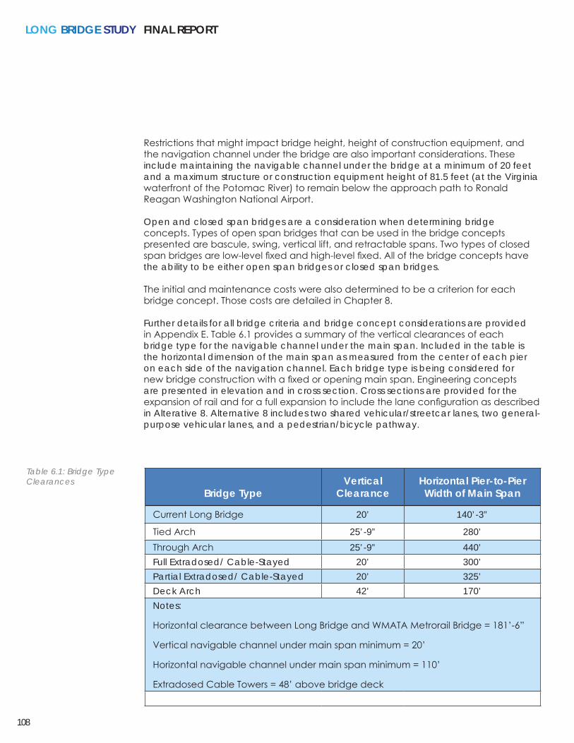
Further details for all bridge criteria and bridge concept considerations are provided in Appendix E. Table 6.1 provides a summary of the vertical clearances of each bridge type for the navigable channel under the main span. Included in the table is the horizontal dimension of the main span as measured from the center of each pier on each side of the navigation channel. Each bridge type is being considered for new bridge construction with a fixed or opening main span. Engineering concepts are presented in elevation and in cross section. Cross sections are provided for the expansion of rail and for a full expansion to include the lane configuration as described in Alterative 8. Alternative 8 includes two shared vehicular/streetcar lanes, two general-purpose vehicular lanes, and a pedestrian/bicycle pathway.
Bridge TypeVertical
ClearanceHorizontal Pier-to-Pier Width of Main Span
Current Long Bridge 20’ 140’-3”
Tied Arch 25’-9” 280’Through Arch 25’-9” 440’Full Extradosed/ Cable-Stayed 20’ 300’Partial Extradosed/ Cable-Stayed 20’ 325’Deck Arch 42’ 170’Notes:
Horizontal clearance between Long Bridge and WMATA Metrorail Bridge = 181’-6”
Vertical navigable channel under main span minimum = 20’
Horizontal navigable channel under main span minimum = 110’
Extradosed Cable Towers = 48’ above bridge deck
Table 6.1: Bridge Type Clearances
CHA
PTER 6: ENG
INEERIN
G C
ON
CEPTS
109
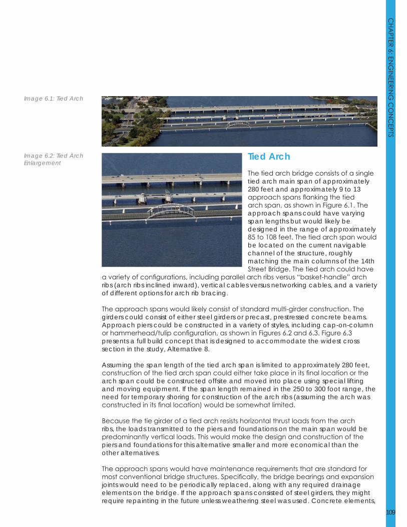
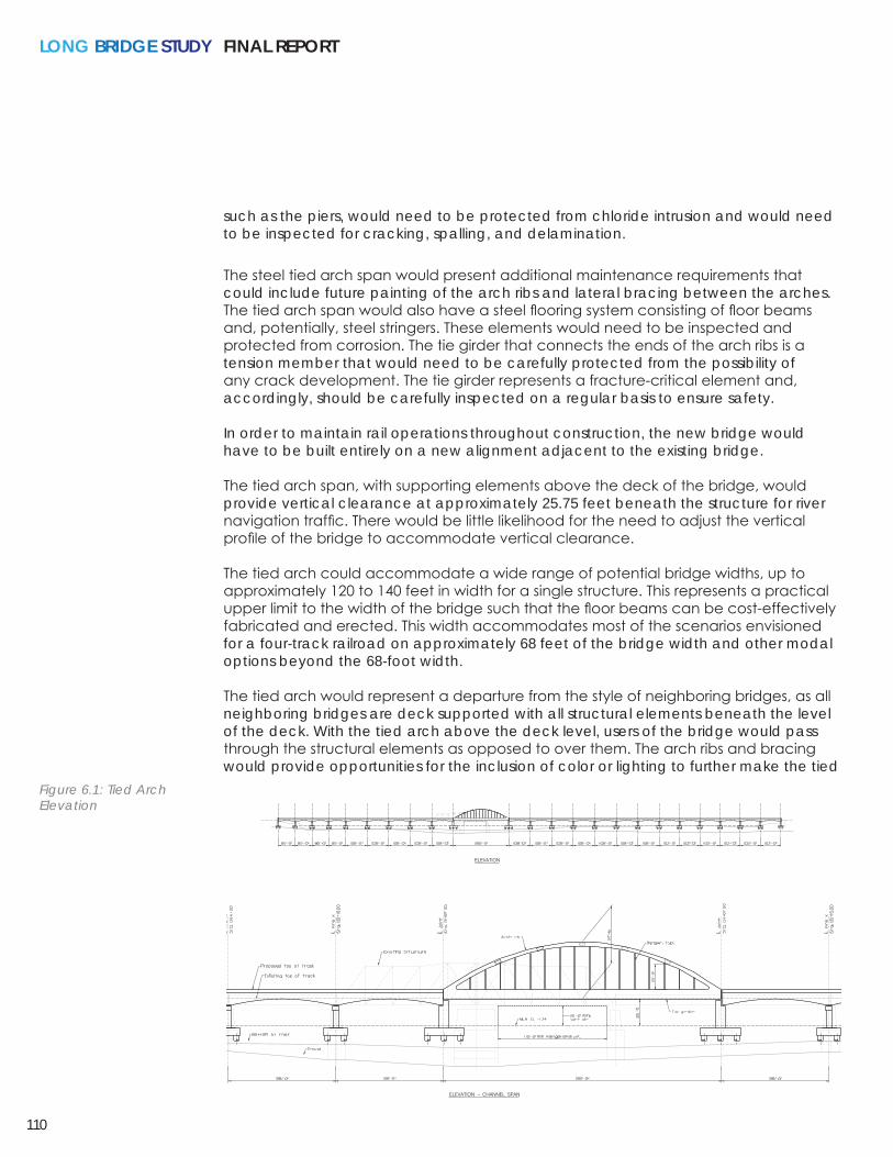
Tied ArchThe tied arch bridge consists of a single tied arch main span of approximately 280 feet and approximately 9 to 13 approach spans flanking the tied arch span, as shown in Figure 6.1. The approach spans could have varying span lengths but would likely be designed in the range of approximately 85 to 108 feet. The tied arch span would be located on the current navigable channel of the structure, roughly matching the main columns of the 14th Street Bridge. The tied arch could have
a variety of configurations, including parallel arch ribs versus “basket-handle” arch ribs (arch ribs inclined inward), vertical cables versus networking cables, and a variety of different options for arch rib bracing.
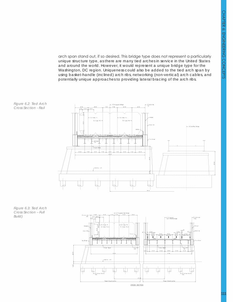
The approach spans would likely consist of standard multi-girder construction. The girders could consist of either steel girders or precast, prestressed concrete beams. Approach piers could be constructed in a variety of styles, including cap-on-column or hammerhead/tulip configuration, as shown in Figures 6.2 and 6.3. Figure 6.3 presents a full build concept that is designed to accommodate the widest cross section in the study, Alternative 8.
Assuming the span length of the tied arch span is limited to approximately 280 feet, construction of the tied arch span could either take place in its final location or the arch span could be constructed offsite and moved into place using special lifting and moving equipment. If the span length remained in the 250 to 300 foot range, the need for temporary shoring for construction of the arch ribs (assuming the arch was constructed in its final location) would be somewhat limited.
Because the tie girder of a tied arch resists horizontal thrust loads from the arch ribs, the loads transmitted to the piers and foundations on the main span would be predominantly vertical loads. This would make the design and construction of the piers and foundations for this alternative smaller and more economical than the other alternatives.
The approach spans would have maintenance requirements that are standard for most conventional bridge structures. Specifically, the bridge bearings and expansion joints would need to be periodically replaced, along with any required drainage elements on the bridge. If the approach spans consisted of steel girders, they might require repainting in the future unless weathering steel was used. Concrete elements,
Image 6.1: Tied Arch
Image 6.2: Tied Arch Enlargement
LONG BRIDGE STUDY FINAL REPORT
110
such as the piers, would need to be protected from chloride intrusion and would need to be inspected for cracking, spalling, and delamination.
The steel tied arch span would present additional maintenance requirements that could include future painting of the arch ribs and lateral bracing between the arches. The tied arch span would also have a steel flooring system consisting of floor beams and, potentially, steel stringers. These elements would need to be inspected and protected from corrosion. The tie girder that connects the ends of the arch ribs is a tension member that would need to be carefully protected from the possibility of any crack development. The tie girder represents a fracture-critical element and, accordingly, should be carefully inspected on a regular basis to ensure safety.
In order to maintain rail operations throughout construction, the new bridge would have to be built entirely on a new alignment adjacent to the existing bridge.
The tied arch span, with supporting elements above the deck of the bridge, would provide vertical clearance at approximately 25.75 feet beneath the structure for river navigation traffic. There would be little likelihood for the need to adjust the vertical profile of the bridge to accommodate vertical clearance.
The tied arch could accommodate a wide range of potential bridge widths, up to approximately 120 to 140 feet in width for a single structure. This represents a practical upper limit to the width of the bridge such that the floor beams can be cost-effectively fabricated and erected. This width accommodates most of the scenarios envisioned for a four-track railroad on approximately 68 feet of the bridge width and other modal options beyond the 68-foot width.
The tied arch would represent a departure from the style of neighboring bridges, as all neighboring bridges are deck supported with all structural elements beneath the level of the deck. With the tied arch above the deck level, users of the bridge would pass through the structural elements as opposed to over them. The arch ribs and bracing would provide opportunities for the inclusion of color or lighting to further make the tied
Figure 6.1: Tied Arch Elevation
CHA
PTER 6: ENG
INEERIN
G C
ON
CEPTS
111
arch span stand out, if so desired. This bridge type does not represent a particularly unique structure type, as there are many tied arches in service in the United States and around the world. However, it would represent a unique bridge type for the Washington, DC region. Uniqueness could also be added to the tied arch span by using basket-handle (inclined) arch ribs, networking (non-vertical) arch cables, and potentially unique approaches to providing lateral bracing of the arch ribs.
Figure 6.2: Tied Arch Cross Section - Rail
Figure 6.3: Tied Arch Cross Section – Full Build)

LONG BRIDGE STUDY FINAL REPORT
112
CHA
PTER 6: ENG
INEERIN
G C
ON
CEPTS
113

LONG BRIDGE STUDY FINAL REPORT
114
Page left blank intentionally.
CHA
PTER 6: ENG
INEERIN
G C
ON
CEPTS
115
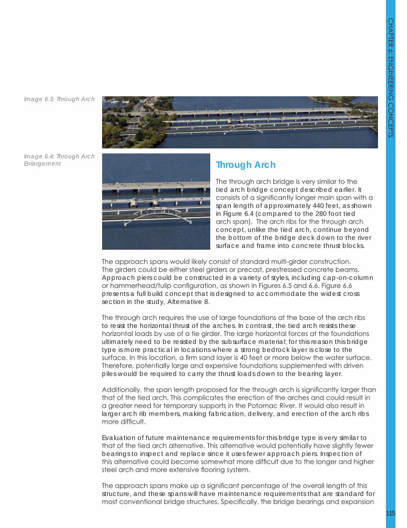
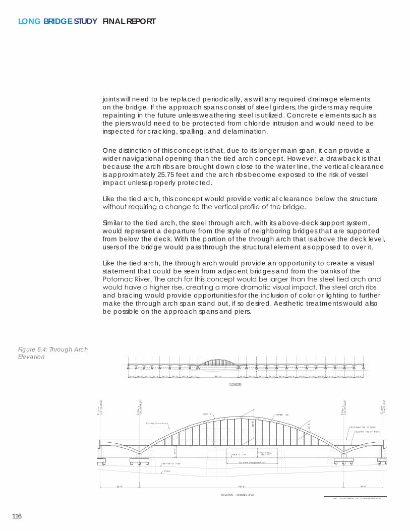
Through ArchThe through arch bridge is very similar to the tied arch bridge concept described earlier. It consists of a significantly longer main span with a span length of approximately 440 feet, as shown in Figure 6.4 (compared to the 280 foot tied arch span). The arch ribs for the through arch concept, unlike the tied arch, continue beyond the bottom of the bridge deck down to the river surface and frame into concrete thrust blocks.
The approach spans would likely consist of standard multi-girder construction. The girders could be either steel girders or precast, prestressed concrete beams. Approach piers could be constructed in a variety of styles, including cap-on-column or hammerhead/tulip configuration, as shown in Figures 6.5 and 6.6. Figure 6.6 presents a full build concept that is designed to accommodate the widest cross section in the study, Alternative 8.
The through arch requires the use of large foundations at the base of the arch ribs to resist the horizontal thrust of the arches. In contrast, the tied arch resists these horizontal loads by use of a tie girder. The large horizontal forces at the foundations ultimately need to be resisted by the subsurface material; for this reason this bridge type is more practical in locations where a strong bedrock layer is close to the surface. In this location, a firm sand layer is 40 feet or more below the water surface. Therefore, potentially large and expensive foundations supplemented with driven piles would be required to carry the thrust loads down to the bearing layer.
Additionally, the span length proposed for the through arch is significantly larger than that of the tied arch. This complicates the erection of the arches and could result in a greater need for temporary supports in the Potomac River. It would also result in larger arch rib members, making fabrication, delivery, and erection of the arch ribs more difficult.
Evaluation of future maintenance requirements for this bridge type is very similar to that of the tied arch alternative. This alternative would potentially have slightly fewer bearings to inspect and replace since it uses fewer approach piers. Inspection of this alternative could become somewhat more difficult due to the longer and higher steel arch and more extensive flooring system.
The approach spans make up a significant percentage of the overall length of this structure, and these spans will have maintenance requirements that are standard for most conventional bridge structures. Specifically, the bridge bearings and expansion
Image 6.3: Through Arch
Image 6.4: Through Arch Enlargement
LONG BRIDGE STUDY FINAL REPORT
116
joints will need to be replaced periodically, as will any required drainage elements on the bridge. If the approach spans consist of steel girders, the girders may require repainting in the future unless weathering steel is utilized. Concrete elements such as the piers would need to be protected from chloride intrusion and would need to be inspected for cracking, spalling, and delamination.
One distinction of this concept is that, due to its longer main span, it can provide a wider navigational opening than the tied arch concept. However, a drawback is that because the arch ribs are brought down close to the water line, the vertical clearance is approximately 25.75 feet and the arch ribs become exposed to the risk of vessel impact unless properly protected.
Like the tied arch, this concept would provide vertical clearance below the structure without requiring a change to the vertical profile of the bridge.
Similar to the tied arch, the steel through arch, with its above-deck support system, would represent a departure from the style of neighboring bridges that are supported from below the deck. With the portion of the through arch that is above the deck level, users of the bridge would pass through the structural element as opposed to over it.
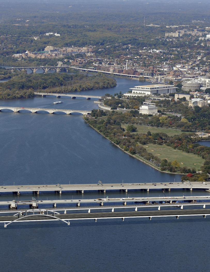
Like the tied arch, the through arch would provide an opportunity to create a visual statement that could be seen from adjacent bridges and from the banks of the Potomac River. The arch for this concept would be larger than the steel tied arch and would have a higher rise, creating a more dramatic visual impact. The steel arch ribs and bracing would provide opportunities for the inclusion of color or lighting to further make the through arch span stand out, if so desired. Aesthetic treatments would also be possible on the approach spans and piers.
Figure 6.4: Through Arch Elevation
CHA
PTER 6: ENG
INEERIN
G C
ON
CEPTS
117
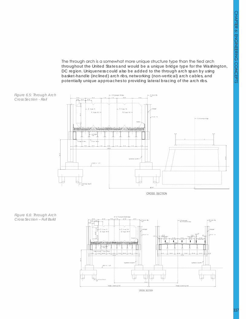
The through arch is a somewhat more unique structure type than the tied arch throughout the United States and would be a unique bridge type for the Washington, DC region. Uniqueness could also be added to the through arch span by using basket-handle (inclined) arch ribs, networking (non-vertical) arch cables, and potentially unique approaches to providing lateral bracing of the arch ribs.
Figure 6.5: Through Arch Cross Section - Rail
Figure 6.6: Through Arch Cross Section – Full Build

LONG BRIDGE STUDY FINAL REPORT
118
CHA
PTER 6: ENG
INEERIN
G C
ON
CEPTS
119

LONG BRIDGE STUDY FINAL REPORT
120
Page left blank intentionally.