structural evaluation of bow string and …€¦ · paper is to evaluate different type of tied...
TRANSCRIPT
http://www.iaeme.com/IJCIET/index.asp 671 [email protected]
International Journal of Civil Engineering and Technology (IJCIET)
Volume 9, Issue 3, March 2018, pp. 671–682, Article ID: IJCIET_09_03_069
Available online at http://www.iaeme.com/ijciet/issues.asp?JType=IJCIET&VType=9&IType=3
ISSN Print: 0976-6308 and ISSN Online: 0976-6316
© IAEME Publication Scopus Indexed
STRUCTURAL EVALUATION OF BOW STRING
AND NETWORK ARCH BRIDGE WITH
DIFFERENT DESIGN PARAMETERS AND
BRACINGS
Ketan Rane
Structural Engineering Department, Vellore Institute of Technology,
Vellore, Tamil Nadu, India
Simon Jayasingh
Assistant Professor, Structural and Geotechnical Department,
Vellore Institute of Technology, Vellore, Tamil Nadu, India
Visuvasam J
Assistant Professor, Structural and Geotechnical Department,
Vellore Institute of Technology, Vellore, Tamil Nadu, India
Suraj Sangtiani
Structural Design Engineer, Pankaj Associates and Consultant Engineers,
Bhopal, Madhya Pradesh, India
ABSTRACT
Tied arch bridges have significant advantages in economical and atheistic
appearance which provide suitable option for bridges of long span. The aim of this
paper is to evaluate different type of tied arch bridges subjected to traffic loading,
wind loading and temperature loading as per IRC code by using MIDAS-Civil
software and comparing the results. To do so, bridge of span 60m sustained by cross
girder 5m apart with rise of arch 15% to 19% of span with one lane and two lane
traffic along with different hanger system such as vertical hanger (bowstring), Neilsen
hanger with different angles and V-hanger system are modeled. Arch height to span
length ratio has significance for optimizing the steel quantity of main girder of bridge
as the arch acts in compression form, due to arch action the forces resolved and
transferred to main girder. By conducting following analysis, two aims are: Eigen
value method is used to find the appropriate wind bracing system for bridge among
cross beam, K-bracing and X-bracing by evaluating and comparing the behavior of
mode shapes, frequency and time period. P-Δ analysis is done to observe the rise in
bending moment in members due to secondary moments caused by the primary
deflections.
Keywords: Bowstring, Neilsen, V-hanger, Cross beam, K-bracing, X-bracing.
Structural Evaluation of Bow String and Network Arch Bridge with Different Design Parameters
and Bracings
http://www.iaeme.com/IJCIET/index.asp 672 [email protected]
Cite this Article: Ketan Rane, Simon Jayasingh, Visuvasam J and Suraj Sangtiani,
Structural Evaluation of Bow String and Network Arch Bridge with Different Design
Parameters and Bracings, International Journal of Civil Engineering and Technology,
9(3), 2018, pp. 671–682.
http://www.iaeme.com/IJCIET/issues.asp?JType=IJCIET&VType=9&IType=3
1. INTRODUCTION
Steel bridges are significant component of infrastructure in structural engineering which
combines economical and atheistic in an innovative way. Arch bridges are special shaped
bridges in which the arch action helps to transfer the load to main girder while being in a pure
compression nature. Tied arch bridges are structure with main girder as a tie member holding
the arch. Tied arch bridge with vertical hangers holding the tie member and arch are known as
bowstring bridges while inclined hangers crossing once between tie member and arch is
known as Neilsen network arch.
As per pervious study P-Δ analysis and influence line diagrams has been used for finding
upper bracing for wind in bowstring bridge [1 and 2]. John Edward Finke and GendaChen
studied dynamic and service condition effects on K-bracing and X-bracing of arch bridges [3].
In a study of mode shapes, E. G. Macias and R.C. Triguero evaluate modal behaviour with
moving load in different lane at opposite directions [4]. In recent researches modal analysis
has been carried about by eigenvalue method analysis for comparing frequencies and time
period [5 and 6]. R Ahsan and N. Islam investigated arch rise to span ratio ith finding
economical arrangement of hanger ore conducted studies conclude the optimum angle of
cross hangers for ielsen arch bridges to be ithin to for different length by
comparing bending moments and axial forces in arch [8 and 9]. For tied arch bridges, the
appropriate rise percentage gives significant advantages for designing economical steel
structure [10, 11, and 12]. N. Pnevmatikos described the importance of box and rectangular
hollow sections over other regular sections for arch member due to advantages in bending and
torsion in bridges [13]. The various hanger arrangements: vertical hanger, with and without
constant slope of hangers, different angle hangers and V-hangers are studied and difference
are investigated to find appropriate hanger system [14,15,16, and 17].
Various types of hanger arrangement according to the system of hangers:
Bowstring system consists of vertical hanger which ties the arch with main girder.
Neilsen systems have inclined hangers with crossing each other at least once. This system is
formed at early 19th century by O. F. Neilsen.
V-hanger system includes the hangers which converge at main girder at one point such as V
shape.
Figure 1 Bowstring Bridge Figure 2 Neilsen Arch
Figure 3 V-Hanger

Ketan Rane, Simon Jayasingh, Visuvasam J and Suraj Sangtiani
http://www.iaeme.com/IJCIET/index.asp 673 [email protected]
2. RESEARCH SIGNIFICANCE
The appropriate rise percentage of arch provides optimum and economical design criteria for
tied arch bridges. This paper shows the results of analytical data for bowstring and other two
types of network arch bridges to identify the optimum rise to span ratio. This study is also
carried out to find the most suitable hanger arrangement for the tied arch bridges with
appropriate wind bracing system for lateral wind load.
3. METHODLOGY
3.1. Problem Statement
All three types of tied arch bridge: a) with vertical hanger b) Neilsen system with different
hanger angles c) with V-hanger system are modeled for 60m span length with varying rise to
span ratio of 15% to 19%. Angle from 60 degree to 65 degree of hangers are varied only for
Neilsen type of bridge. Height of structure above the ground is assumed as 10m and Mumbai
region is taken for temperature and wind calculation. The slab thickness and wearing coat
thickness is taken as 200mm and 75mm. Bridges are modeled for one lane (total width 6m
with 5m carriageway) and two lane (total width 10m with 9m carriageway).
3.2. Modelling
In this study, the rise to span ratio for all three type of tied arch bridges has been varied from
15% to 19% of span length with three different types of wind bracing. While for Neilsen arch
bridges with different angle of hangers, the angle between hangers and main girder are been
varied within 60 degree to 65 degree for studying the optimum angle in Neilsen arch system.
Following are the various rise to span ratio 15% to 19%, figures for 60m span length: -
Figure 4 15%, 16% and 17% arch rise to span ratio
Figure 5 18% and 19% arch rise to span ratio
Different angle arrangement from 60 degree to 65 degree for Neilson tied arch models for
different angles are shown in figure: -
Figure 6 Different angle for hanger arrangement

Structural Evaluation of Bow String and Network Arch Bridge with Different Design Parameters
and Bracings
http://www.iaeme.com/IJCIET/index.asp 674 [email protected]
Models by varying both rise to span ratio and type of bracing for bowstring and V-hanger
system: -
Figure 7 Bowstring with Figure 8 Bowstring with Figure 9 Bowstring with
Cross Beam K-bracing X-bracing
Figure 10 V-hanger with Figure 11 V-hanger with Figure 12 V-hanger with
Cross Beam K-bracing X-bracing
Models for Neilsen arch with different angles in combination with change in rise to span
ratio, type of bracing and angle of hangers: -
Figure 13 Neilsen arch with Figure 14 Neilsen arch with Figure 15 Neilsen arch with
Cross Beam K-bracing X-bracing
3.3. Parameters
3.3.1. Element and Boundary Condition
MIDAS-Civil software is used for modeling structural elements of tied-arch bridge. Hangers
and bracing members are modeled as a truss member to transfer the axial force only, no
bending moments will not come for these members. Pined supports are applied at all end
nodes of the arch at both ends.
3.3.2. Beam End Release
Beam end release are provided at end nodes of all cross girders, so that bending moments at
the end node of cross girder gets zero and transferred to the main girder. Bending moment in

Ketan Rane, Simon Jayasingh, Visuvasam J and Suraj Sangtiani
http://www.iaeme.com/IJCIET/index.asp 675 [email protected]
arch is carried over to main girder by applying beam end releases at all four end modes of
arch which causes zero bending moment at end nodes of arch.
3.3.3. Section
I sections are efficient in flexural behavior, as the web increases the shear capacity and
flanges resist the bending moments. Rectangular hollow section for arch element and square
hollow section for bracing element is used due to high bending and twisting resistance with
aesthetic advantages and light weight properties. Hangers are generally solid circular rods
which are considered only as a truss member and designed for axial force only.
3.3.4. Material Properties
Strength is the main criteria for bridge designing which requires high steel grades.
Economical and optimum dimensions and efficient weight can be achieved by using high
grade steel which provides high strength and durability.
Table 1 Material Properties
Properties Value
Steel
Steel grade Fe 590
Modulus of elasticity 2.05e+08 kN/m2
Poisson’s ratio 0.3
Thermal coefficient 1.2e-05 1/C
Density 76.98 kN/m3
Concrete
Density 25 kN/m3
Wearing coat
Density 22 kN/m3
3.4. Loading
Loading calculations has been done according to IRC codes which are used for bridge
designing. Vehicular loads applied with different load condition as stated in the code due to
different lanes. These vehicular loads are applied on the basis of highways, industrial and
specified area, type of bridge, heavy load movement.
Wind, temperature and live load calculations are done refereeing to IRC 6 code. Live load
combinations for design purpose are applied on the basis of number of lanes. For one lane
carriageway (width 4.25m to 5.3m), class A vehicle is placed at a distance minimum of 0.15m
from the carriageway edge to vehicle outer tyre and remaining part of carriageway is loaded
with uniform intensity of 500 kg/m2throughout the length. For two lane carriageway (width
5.3m to 9.6m), vehicle of class 70R is applied at a distance minimum of 1.2m from the
carriageway edge to vehicle outer tyre in first case. While in second case for two lane, two
class A vehicle is being placed on carriage way with 1.2m distance between both the vehicles
and the outer class A vehicle tyre will be minimum 0.15m away from the carriageway edge.
The standard centre to centre of tyre distance for class A vehicle is 1.8m and centre to centre
distance of tyre for class 70R is 1.93m. Weight of slab and wearing coat is converted into load
and applied as a floor load in two way distribution, due to which the load distribution takes
place on both cross girder and main girder properly.
Structural Evaluation of Bow String and Network Arch Bridge with Different Design Parameters
and Bracings
http://www.iaeme.com/IJCIET/index.asp 676 [email protected]
4. RESULTS AND DISCUSSION
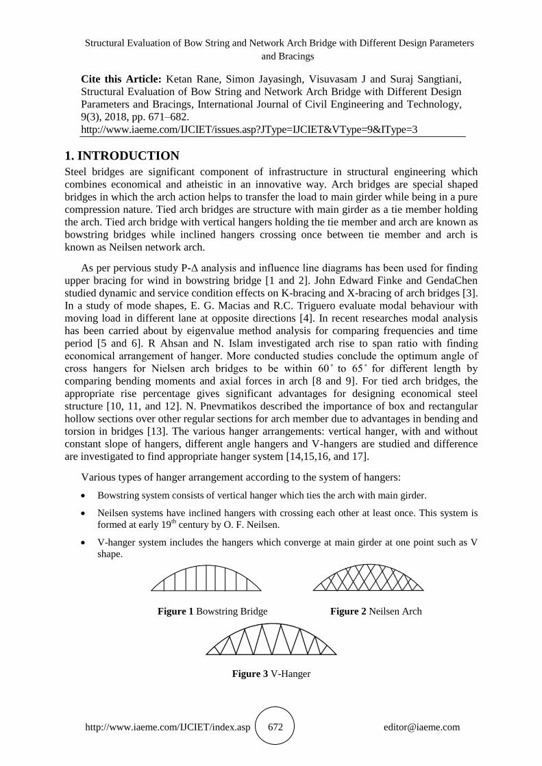
4.1. Bending Moment Variation in Main Girder
Rise and drop variation in main girder is observed for identifying the optimum rise to span
ratio for various different type of tied arch. Approximately 45% to 55% of steel is required for
main girder as compare to whole steel bridge structure. The minimum bending moment and
shear force is observed at different percentage of rise which recommends the lesser quantity
of steel section is required and gives the economical design. The same behavior is observed in
arch and hangers. 25% to 35% of steel quantity of bridge is generally needed for arch section.
Due to maximum steel quantity of main girder, the variation in main girder is observed and
recorded for concluding the optimum rise to span ratio.
4.1.1. One Lane Bowstring and V-Hanger Main Girder Result Comparison
Figure 16 Bowstring One lane (BM) Figure 17 V-Hanger One Lane (BM)
4.1.2. One Lane Neilsen Arch Main Girder Result Comparison
Figure 18 Neilsen Arch One Lane Figure 19 Neilsen Arch One Lane
Cross Beam (BM) K-bracing (BM)
Figure 20 Neilsen Arch One Lane X-bracing (BM)
1500
1700
1900
2100
2300
2500
2700
2900
15 16 17 18 19
BE
ND
ING
MO
ME
NT
BOWSTRING ONE LANE (BENDING MOMENT)
BM CROSS BEAM
BM K-BRACING
BM X-BRACING
600
650
700
750
800
850
15 16 17 18 19
BE
ND
ING
MO
ME
NT
V-HANGER ONE LANE (BENDING MOMENT)
BM CROSS BEAM
BM K-BRACING
BM X-BRACING
400
450
500
550
600
650
700
750
800
850
15 16 17 18 19
BE
ND
ING
MO
ME
NT
NEILSEN ARCH ONE LANE CROSSBEAM (BENDING
MOMENT)
BM 60 CROSS
BEAM
BM 61 CROSS
BEAM
BM 62 CROSS
BEAM
BM 63 CROSS
BEAM
BM 64 CROSS
BEAM 400
450
500
550
600
650
700
750
800
850
15 16 17 18 19
BE
ND
ING
MO
ME
NT
NEILSEN ARCH ONE LANE K-BRACING (BENDING
MOMENT)
BM 60 K-BRACING
BM 61 K-BRACING
BM 62 K-BRACING
BM 63 K-BRACING
BM 64 K-BRACING
BM 65 K-BRACING
400
450
500
550
600
650
700
750
800
15 16 17 18 19
BE
ND
ING
MO
ME
NT
NEILSEN ARCH ONE LANE X-BRACING (BENDING MOMENT)
BM 60 X-BRACING
BM 61 X-BRACING
BM 62 X-BRACING
BM 63 X-BRACING
BM 64 X-BRACING
BM 65 X-BRACING

Ketan Rane, Simon Jayasingh, Visuvasam J and Suraj Sangtiani
http://www.iaeme.com/IJCIET/index.asp 677 [email protected]
4.1.3. Two Lane Bowstring and V-Hanger Main Girder Result Comparison
Figure 21 Bowstring Two lane (BM) Figure 22 V-Hanger Two Lane (BM)
4.1.4. Two Lane Neilsen Arch Main Girder Result Comparison
Figure 23 Neilsen Arch Two Lane Figure 24 Neilsen Arch Two Lane
Cross Beam (BM) K-bracing (BM)
Figure 25 Neilsen Arch Two Lane X-bracing (BM)
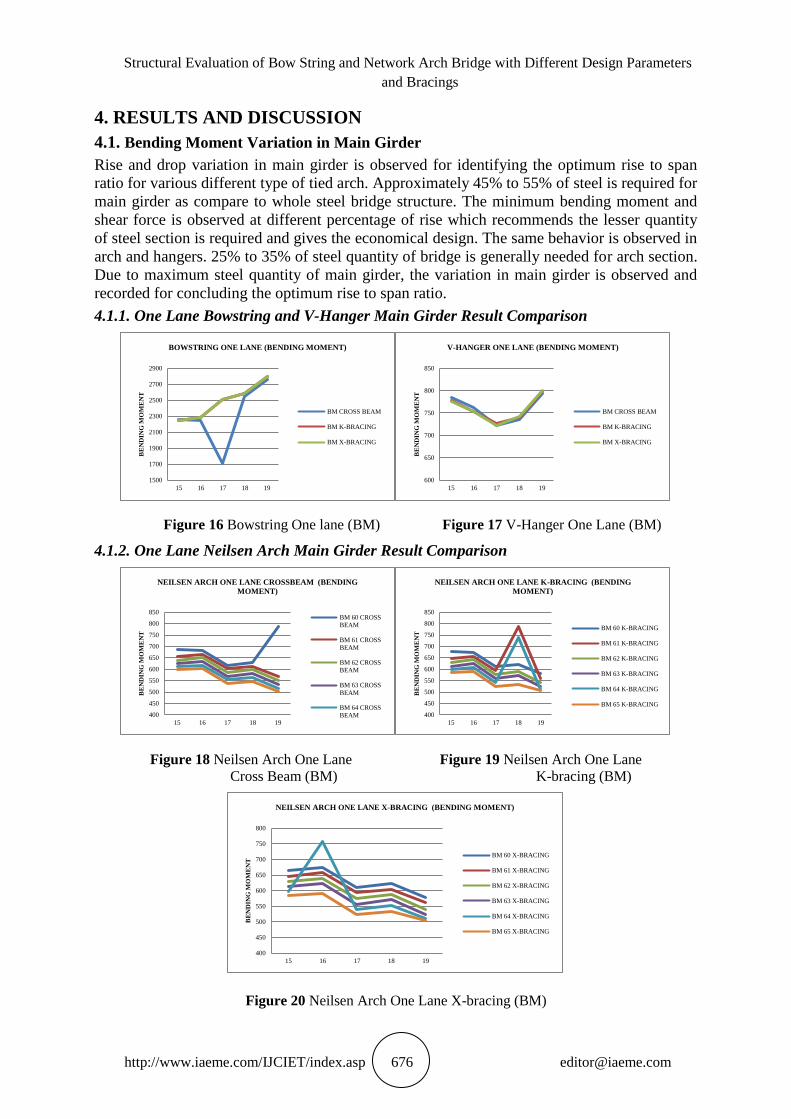
4.2. Modal Analysis
Vibration occurs at particular frequencies which causes mode shapes of structure and can be
observed by doing analytically modal analysis. Steel structural elements are very vulnerable
to vibrations. Modal analysis helps to identify the appropriate wind bracing system by
comparing frequency at first 3 modes of the structure. More frequency indicates more
stiffness, which provides more strength to the structure.
1500
2000
2500
3000
3500
4000
4500
15 16 17 18 19
BE
ND
ING
MO
ME
NT
BOWSTRING TWO LANE (BENDING MOMENT)
BM CROSS BEAM
BM K-BRACING
BM X-BRACING
1200
1250
1300
1350
1400
1450
1500
1550
1600
1650
15 16 17 18 19
BE
ND
ING
MO
ME
NT
V-HANGER TWO LANE (BENDING MOMENT)
BM CROSS BEAM
BM K-BRACING
BM X-BRACING
1000
1100
1200
1300
1400
1500
1600
15 16 17 18 19
BE
ND
ING
MO
ME
NT
NEILSEN ARCH TWO LANE CROSSBEAM (BENDING
MOMENT)
BM 60 CROSS
BEAM
BM 61 CROSS
BEAM
BM 62 CROSS
BEAM
BM 63 CROSS
BEAM
BM 64 CROSS
BEAM 400
600
800
1000
1200
1400
1600
1800
15 16 17 18 19
BE
ND
ING
MO
ME
NT
NEILSEN ARCH TWO LANE K-BRACING (BENDING
MOMENT)
BM 60 K-BRACING
BM 61 K-BRACING
BM 62 K-BRACING
BM 63 K-BRACING
BM 64 K-BRACING
BM 65 K-BRACING
400
600
800
1000
1200
1400
1600
15 16 17 18 19
BE
ND
ING
MO
ME
NT
NEILSEN ARCH TWO LANE X-BRACING (BENDING MOMENT)
BM 60 X-BRACING
BM 61 X-BRACING
BM 62 X-BRACING
BM 63 X-BRACING
BM 64 X-BRACING
BM 65 X-BRACING

Structural Evaluation of Bow String and Network Arch Bridge with Different Design Parameters
and Bracings
http://www.iaeme.com/IJCIET/index.asp 678 [email protected]
4.2.1. Modal Analysis for One Lane Bowstring and V-Hanger with 17% Rise
Figure 26 Frequency - Bowstring One Lane Figure 27 Frequency - V-Hanger One Lane
4.2.2. Modal Analysis for One Lane Neilsen Arch with 17% Rise
Figure 28 Frequency - Neilsen Arch Figure 29 Frequency - Neilsen Arch
One Lane 60degree One Lane 65degree
4.2.3. Modal Analysis for Two Lane Bowstring and V-Hanger with 17% Rise
Figure 30 Frequency - Bowstring Two Lane Figure 31 Frequency - V-Hanger Two Lane
0.13638
0.415289
0.506055
0.12074
0.482857
0.583219
0.12074
0.482857
0.581473
1st MODE
2nd MODE
3rd MODE
BOWSTRING - ONE LANE FREQUENCY
X-BRACING K-BRACING CROSS BEAM
0.120559
0.39089
0.482231
0.120559
0.482231
0.582936
0.120559
0.482231
0.581578
1st MODE
2nd MODE
3rd MODE
V-HANGER - ONE LANE FREQUENCY
X-BRACING K-BRACING CROSS BEAM
0.120523
0.389994
0.482104
0.120523
0.482104
0.582503
0.120523
0.482104
0.581226
1st MODE
2nd MODE
3rd MODE
NEILSEN ONE LANE - 60 ̊ FREQUENCY
X-BRACING K-BRACING CROSS BEAM
0.120538
0.390423
0.482166
0.120538
0.482166
0.582287
0.120538
0.482166
0.580997
1st MODE
2nd MODE
3rd MODE
NEILSEN ONE LANE - 65 ̊ FREQUENCY
X-BRACING K-BRACING CROSS BEAM
0.107284
0.369338
0.40623
0.096203
0.384697
0.565508
0.096203
0.384697
0.55264
1st MODE
2nd MODE
3rd MODE
BOWSTRING - TWO LANE FREQUENCY
X-BRACING K-BRACING CROSS BEAM
0.096111
0.352077
0.38438
0.096111
0.38438
0.562287
0.096111
0.38438
0.549861
1st MODE
2nd MODE
3rd MODE
V-HANGER - TWO LANE FREQUENCY
X-BRACING K-BRACING CROSS BEAM
Ketan Rane, Simon Jayasingh, Visuvasam J and Suraj Sangtiani
http://www.iaeme.com/IJCIET/index.asp 679 [email protected]
4.2.4. Modal Analysis for Two Lane Neilsen Arch with 17% Rise
Figure 32 Frequency - Neilsen Arch Figure 33 Frequency - Neilsen Arch
Two Lane 60degree Two Lane 65degree
4.3. P-Delta Analysis
Due to primary deflection of the structure, more forces are generated due to structural
irregularity which causes additional moments in members by induced secondary shear force.
The generated load multiplied by the displacement horizontally occurred gives the generated
moment. The instability of system caused due to generated force increases the instability. The
adverse effect of wind and seismic load can be observed by doing P-delta analysis. The effect
of p delta analysis is observed in main girder, arch and hanger.
4.3.1. Percentage Increase in Bending Moment of One Lane Bowstring with 17% Rise
Table 2 P-delta Percentage Increase - Bowstring One Lane
Bowstring One Lane 17
Type of Bracing Cross Beam K-bracing X-bracing
Increase in Main Girder Bending Moment (%) 3.586162 3.458673 3.490115
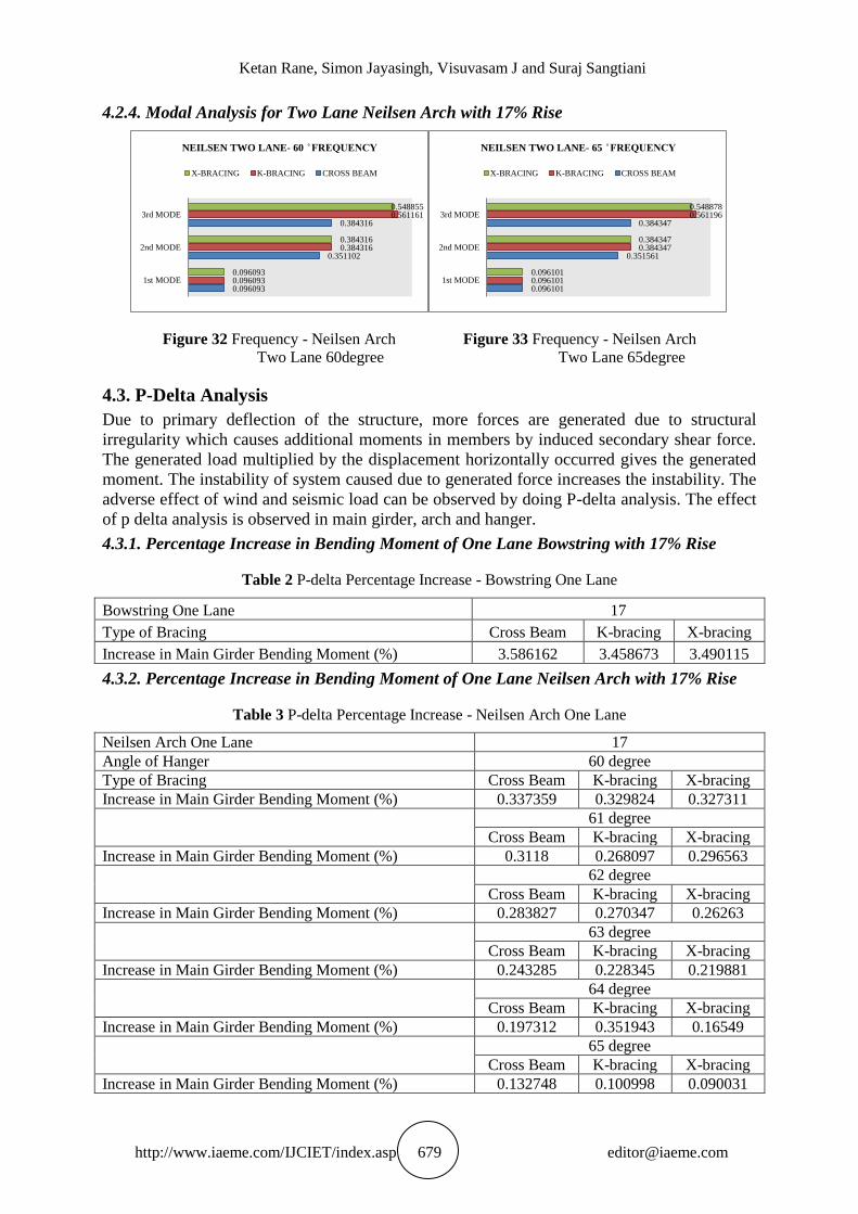
4.3.2. Percentage Increase in Bending Moment of One Lane Neilsen Arch with 17% Rise
Table 3 P-delta Percentage Increase - Neilsen Arch One Lane
Neilsen Arch One Lane 17
Angle of Hanger 60 degree
Type of Bracing Cross Beam K-bracing X-bracing
Increase in Main Girder Bending Moment (%) 0.337359 0.329824 0.327311
61 degree
Cross Beam K-bracing X-bracing
Increase in Main Girder Bending Moment (%) 0.3118 0.268097 0.296563
62 degree
Cross Beam K-bracing X-bracing
Increase in Main Girder Bending Moment (%) 0.283827 0.270347 0.26263
63 degree
Cross Beam K-bracing X-bracing
Increase in Main Girder Bending Moment (%) 0.243285 0.228345 0.219881
64 degree
Cross Beam K-bracing X-bracing
Increase in Main Girder Bending Moment (%) 0.197312 0.351943 0.16549
65 degree
Cross Beam K-bracing X-bracing
Increase in Main Girder Bending Moment (%) 0.132748 0.100998 0.090031
0.096093
0.351102
0.384316
0.096093
0.384316
0.561161
0.096093
0.384316
0.548855
1st MODE
2nd MODE
3rd MODE
NEILSEN TWO LANE- 60 ̊ FREQUENCY
X-BRACING K-BRACING CROSS BEAM
0.096101
0.351561
0.384347
0.096101
0.384347
0.561196
0.096101
0.384347
0.548878
1st MODE
2nd MODE
3rd MODE
NEILSEN TWO LANE- 65 ̊ FREQUENCY
X-BRACING K-BRACING CROSS BEAM
Structural Evaluation of Bow String and Network Arch Bridge with Different Design Parameters
and Bracings
http://www.iaeme.com/IJCIET/index.asp 680 [email protected]
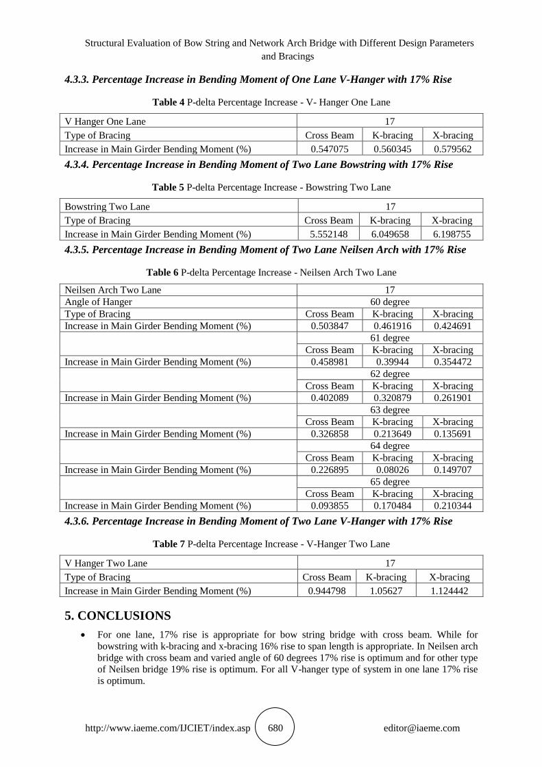
4.3.3. Percentage Increase in Bending Moment of One Lane V-Hanger with 17% Rise
Table 4 P-delta Percentage Increase - V- Hanger One Lane
V Hanger One Lane 17
Type of Bracing Cross Beam K-bracing X-bracing
Increase in Main Girder Bending Moment (%) 0.547075 0.560345 0.579562
4.3.4. Percentage Increase in Bending Moment of Two Lane Bowstring with 17% Rise
Table 5 P-delta Percentage Increase - Bowstring Two Lane
Bowstring Two Lane 17
Type of Bracing Cross Beam K-bracing X-bracing
Increase in Main Girder Bending Moment (%) 5.552148 6.049658 6.198755
4.3.5. Percentage Increase in Bending Moment of Two Lane Neilsen Arch with 17% Rise
Table 6 P-delta Percentage Increase - Neilsen Arch Two Lane
Neilsen Arch Two Lane 17
Angle of Hanger 60 degree
Type of Bracing Cross Beam K-bracing X-bracing
Increase in Main Girder Bending Moment (%) 0.503847 0.461916 0.424691
61 degree
Cross Beam K-bracing X-bracing
Increase in Main Girder Bending Moment (%) 0.458981 0.39944 0.354472
62 degree
Cross Beam K-bracing X-bracing
Increase in Main Girder Bending Moment (%) 0.402089 0.320879 0.261901
63 degree
Cross Beam K-bracing X-bracing
Increase in Main Girder Bending Moment (%) 0.326858 0.213649 0.135691
64 degree
Cross Beam K-bracing X-bracing
Increase in Main Girder Bending Moment (%) 0.226895 0.08026 0.149707
65 degree
Cross Beam K-bracing X-bracing
Increase in Main Girder Bending Moment (%) 0.093855 0.170484 0.210344
4.3.6. Percentage Increase in Bending Moment of Two Lane V-Hanger with 17% Rise
Table 7 P-delta Percentage Increase - V-Hanger Two Lane
V Hanger Two Lane 17
Type of Bracing Cross Beam K-bracing X-bracing
Increase in Main Girder Bending Moment (%) 0.944798 1.05627 1.124442
5. CONCLUSIONS
For one lane, 17% rise is appropriate for bow string bridge with cross beam. While for
bowstring with k-bracing and x-bracing 16% rise to span length is appropriate. In Neilsen arch
bridge with cross beam and varied angle of 60 degrees 17% rise is optimum and for other type
of Neilsen bridge 19% rise is optimum. For all V-hanger type of system in one lane 17% rise
is optimum.
Ketan Rane, Simon Jayasingh, Visuvasam J and Suraj Sangtiani
http://www.iaeme.com/IJCIET/index.asp 681 [email protected]
Same optimum ratios for bowstring and Neilson arch bridge is been observed for two lane
bridge. But for V-hanger type of bridge, 18% rise to span ratio is optimum.
K-bracing is most efficient type of bracing system for both one lane and two lane as seen after
comparing the results of frequencies calculated by modal analysis.
Increase of 3.46 to 3.59% of bending moment in main girder is observed in one lane
bowstring, in Neilson arch bridge 0.1 to 0.35% of increase is observed while, in V-hanger 0.55
to 0.58%. In two lane bridge, 5.55 to 6.2% of additional moment is observed in bowstring and
for Neilsen arch and V-hanger system increase in bending moment due to initial displacement
is noted as 0.08 to 0.51% and 0.94 to 1.12% respectively. Which shows the less change or
increase in bending moment of main girder in Neilsen arch bridges as compare to other type of
bridges.
Approximate minimum steel quantity weight of bowstring main girder for one lane is 7.02
kN/m and for main girder of Neilsen arch is 5.67 kN/m while for V-hanger system the steel
requirement for main girder is 6.22 kN/m. Two lane main girder of bowstring requires
minimum steel quantity of 8.22 kN/m and 6.75 kN/m amount of approximate steel is require
for Neilsen arch while 7.17 kN/m for V hanger is calculated minimum approximately for
considered loading.
REFERENCES
[1] Răcănel, Ionuţ Radu, Vlad Daniel Urdăreanu, and Andrei Radu "“Bo string” Arches in
Langer System Without Wind Bracing." Romanian Journal of Transport
Infrastructure 4.1 (2015): 67-77.
[2] Namin, Aria Aghajani. “Structural evaluation of tied-arch and truss bridges subjected to
wind and traffic loading.” Diss. Eastern Mediterranean University (EMU), 2012.
[3] Finke JE. “Static and dynamic characterization of tied arch bridges”. Missouri University
of Science and Technology; 2016.
[4] acıas EG, Castro-Triguero R, Gallego R, Carretero J, Gómez-Casero M. “Operational
Modal Analysis and Detection of Non-Linear Structural Behavior of Bowstring Arch
Bridge.”
[5] Ribeiro, Diogo, et al. "Finite element model updating of a bowstring-arch railway bridge
based on experimental modal parameters." Engineering Structures 40 (2012): 413-435.
[6] Qiu, Wen-Liang, et al. "Stability Analysis of Special-Shape Arch Bridge." 淡江理工學刊 13.4 (2010): 365-373.
[7] Islam, N., and R. Ahsan. "Optimization of hanger arrangement of network arch
bridges." Proceedings of the IABSE-JSCE Joint Conference on Advances in Bridge
Engineering-II. 2010. 8–10.
[8] Vlad, Mihai, Gavril Kollo, and Vladimir Marusceac. "A Modern Approach to Tied-Arch
Bridge Analysis and Design." Buletinul Institutului Politehnic din lasi. Sectia Constructii,
Arhitectura 61.2 (2015): 75.
[9] Tveit, P. "Preliminary Design of Network Arch Road Bridges–Examples with Spans of
135 and 160 m." (2003).
[10] Beyer, William Edward. “Preliminary analysis and hanger adjustment of tied arch
bridges.” Diss. Montana State University-Bozeman, College of Engineering, 1984.
[11] Beyer, Lily. "History of Arched Bridges in New Hampshire ” (2012).
[12] Pedro Pereira Clemente Andrade Gonçalves “Preliminary Design of a Bowstring tied-
arch deck.” (2012).

Structural Evaluation of Bow String and Network Arch Bridge with Different Design Parameters
and Bracings
http://www.iaeme.com/IJCIET/index.asp 682 [email protected]
[13] Nikos Pnevmatikos “Standard bridge beams with spans up to 100m for road, rail and
walkway bridges.” (2 1 )
[14] Varennes, Maxime. "Design of a single-track railway network arch bridge: According to
the Eurocodes." (2011).
[15] da Costa, Bernardo Morais. “Design and Analysis of a Network Arch Bridge.” Novas
Edições Acadêmicas, 2017.
[16] Smit, T. J. M. "Design and construction of a railway arch bridge with a network hanger
arrangement." Journal of Civil Engineering Research 2013, Delft University of
technology, pg 1 214 (2013).
[17] Mato, Francisco Millanes, Miguel Ortega Cornejo, and Jorge Nebreda Sanchez. "Design
and Construction of Composite Tubular Arches with Network Suspension System: Recent
Undertakings and Trends." Journal of Civil Engineering and Architecture 5.3 (2011).
[18] Steen, George Perry. "Design study of a three span continuous tied-arch bridge." (1939).
[19] Koshi, Alika, and Laju Kottalil. "Performance Comparison of Through Arch Bridge at
Different Arch Positions." International Journal of Scientific & Engineering Research,
2016, pp. 515–518.
[20] Gogou, Eleni. "Use of high strength steel grades for economical bridge design." (2012).
[21] A. R. Krishnan, R. Leslie and Unnikrishnan S “Damage Detection in Bowstring Girder
Bridge using Dynamic Characteristics.” International Journal of Engineering Research &
Technology (IJERT), 2015, pp. 168–171.
[22] IRC 6: “Standard Specifications and Code of Practice for Road Bridges, Section II –
Loads and Stresses ”
[23] IRC 24: “Standard Specifications and Code of Practice for Road Bridges, Section V –
Steel Road Bridges ”
[24] IS 800:2007 “General Construction In Steel - Code Of Practice ”