chapter 6. membrane process (carrier mediated...
TRANSCRIPT

Chang-Han Yun / Ph.D.
National Chungbuk University
November 17, 2015 (Wed)
Chapter 6. Membrane Process
(Carrier Mediated Transport)

2 Chapter 6. Membrane Process(Concentration) Chungbuk University
Contents
Contents Contents
6.5 Other Driving Force
6.4 Concentration Driving Force
6.3 Pressure Driven Force
6.2 Osmosis
6.1 Introduction

3 Chapter 6. Membrane Process(Concentration) Chungbuk University
6.4 Concentration Driving Force 6.4.4 Carrier
mediated transport
Membrane supply an interphase between two phases
Liquid as a membrane
Liquid membrane or Liquid film separates two phases from each other.
Differences in solubility and diffusivity in the liquid film ⇨ occur separation
Carrier
Contained at the inside of the membrane
Ability to complex with a specific solute to enhance the flux of solute
Characteristic of a facilitated or carrier mediated transport
Reversible chemical reaction(complexation) process + Diffusion process
① Diffusion = rate-limiting (fast reaction) ⇨ mainly occur in most of case
② Reaction = rate-limiting (slow reaction and relatively fast diffusion)

4 Chapter 6. Membrane Process(Concentration) Chungbuk University
6.4 Concentration Driving Force 6.4.4 Carrier
mediated transport
[Table 6-17] Diffusivities in carrier mediated
systems
System D(cm2/s)
Mobile carrier system
Solvent swollen or gel system
Fixed carrier
10–7 ∼ 10–5
10–8 ∼ 10–6
> 10–7
<Figure 6-29> Schematic drawing of a mobile carrier system (left) and a fixed carrier system (right).
Mobile or fixed type carrier(<Figure 6-29>)
Mobile type : Carrier dissolved in the liquid
• Carrier-solute complex diffuses across
the membrane.
• Higher diffusivity in the mobile system
Fixed type : Carrier bound chemically or
physically to a solid polymer
• Very restricted mobility
• Solute jumps or 'hops' from one site to
the other
5 Chapter 6. Membrane Process(Concentration) Chungbuk University
6.4 Concentration Driving Force 6.4.4 Carrier
mediated transport
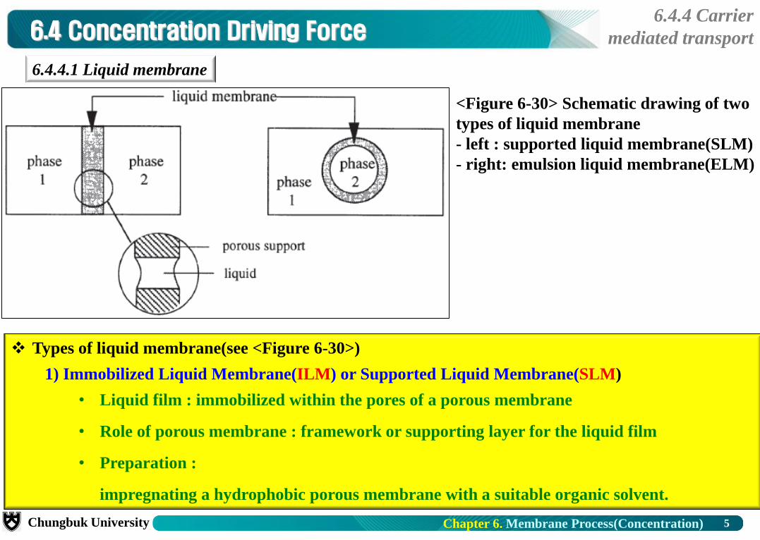
6.4.4.1 Liquid membrane
Types of liquid membrane(see <Figure 6-30>)
1) Immobilized Liquid Membrane(ILM) or Supported Liquid Membrane(SLM)
• Liquid film : immobilized within the pores of a porous membrane
• Role of porous membrane : framework or supporting layer for the liquid film
• Preparation :
impregnating a hydrophobic porous membrane with a suitable organic solvent.
<Figure 6-30> Schematic drawing of two
types of liquid membrane
- left : supported liquid membrane(SLM)
- right: emulsion liquid membrane(ELM)

6 Chapter 6. Membrane Process(Concentration) Chungbuk University
6.4 Concentration Driving Force 6.4.4 Carrier
mediated transport
2) Preparation of ELM (<Figure 6-31>)
① Mix 2 immiscible phases vigorously with surfactant to stabilize the emulsion
⇨ form stable emulsion droplets (droplet size : 0.5 ∼ 10 μm)
② Add emulsion to aqueous phase ⇨ form W-O-W emulsion ⇨ Oil phase = Liquid membrane
※ Phase 1 and phase 2 : generally aqueous solutions
Liquid membrane phase : organic phase (immiscible with water)
※ Solubility of organic to water : very important factor to stabilize system
<Figure 6-31> Preparation of ELM.

7 Chapter 6. Membrane Process(Concentration) Chungbuk University
6.4 Concentration Driving Force 6.4.4 Carrier
mediated transport
Selectivity of LM : Low ⇨ only used in some specific applications
Solubility & Diffusivity ⇨ Selectivity
• Diffusivity : components size = similar ⇨ diffusivity = not much difference
• Solubility : difference in distribution coefficient of species i among W-O-W
Difference in distribution coefficient of species i among W-O-W ⇨ Selectivity
Without carrier, difference in diffusivity and solubility = low ⇨ low selectivity
Carrier-mediated transport or Facilitated transport (<Figure 6-32>)
Carrier : Accelerate the transport of specific component ⇨ Selectivity↑

8 Chapter 6. Membrane Process(Concentration) Chungbuk University
6.4 Concentration Driving Force 6.4.4 Carrier
mediated transport
U-tube experiment
Bottom of an U-tube : organic (higher density than water)
One arm of the U-tube : aqueous KCl solution
Organic phase : chloroform containing carrier(18-crown ether-6 : a high affinity to KCl salt)
Salt transport by ΔcKCl from high concentrated solution to pure water phase
• Without carrier : very low transport of salt (∵ KCl solubility to chloroform = very low)
• With carrier : form a reversible complex with the salt ⇨ transport of K
<Figure 6-33> 8-crown-6 complexed
with a potassium ion.
Other arm of the U-tube : pure water
[Figure 6-32] U-tube experiment to
demonstrate facilitated transport.

9 Chapter 6. Membrane Process(Concentration) Chungbuk University
6.4 Concentration Driving Force 6.4.4 Carrier
mediated transport
Carrier-mediated transport
Carrier molecule(C) : Enhance transport of component A (A+C → complex AC)
Coupled transport (<Figure 6-34>)
2 components are involved in carrier mediated-transport
Co-transport : 2 components are moving in the same direction
Counter-transport : 2 components are moving in opposite directions
Decomplexation in the opposing phases
Transport : low → high concentration
∵ Real driving force :
concentration gradient of complex(C)
<Figure 6-34> Transport mechanism in a liquid
membrane.
Left : Diffusive transport(without carrier)
Right : Facilitated transport(with carrier C)
Facilitated transport
uncoupled
Diffusive transport
(without carrier)
coupled

10 Chapter 6. Membrane Process(Concentration) Chungbuk University
6.4 Concentration Driving Force 6.4.4 Carrier
mediated transport
Transport mechanism
① Dissolving solute of aqueous phase 1(feed phase) into the membrane
② Complexation between the carrier and the solute at the phase 1 interface
③ Diffusion of carrier-solute complex to opposite interface through liquid membrane
④ Decomplexation at phase 2(stripping phase or receiving phase) interface
⑤ Releasing solute from the membrane to phase 2
⑥ Diffusion of free carrier back to phase 1 interface through membrane
<Figure 6-35> The mechanism of carrier-mediated transport
in liquid membranes with mobile carriers.

11 Chapter 6. Membrane Process(Concentration) Chungbuk University
6.4 Concentration Driving Force 6.4.4 Carrier
mediated transport
Basic feature of carrier-mediated transport
Complexation reaction = reversible
Affinity between the carrier and the solute = very high
• Strong complex ⇨ slow release
• Weak complex ⇨ only limited facilitation occurs ⇨ selectivity =low
• Bond energies of these reversible complexes = range of 10 ∼ 50 kJ/mol
※ Similar bond energy : H-bonding, acid-base interactions, chelation, π bond interactions
Effects contribute to the transport of component A
① Rate of complexation / decomplexation at the two interfaces
② Diffusion of the complex (and the free solutes) across the membrane
Another characteristics of facilitated transport
Flux = not proportional anymore to the driving force
At (very) low concentrations in feed phase, still appreciable fluxes can be obtained.

12 Chapter 6. Membrane Process(Concentration) Chungbuk University
6.4 Concentration Driving Force 6.4.4 Carrier
mediated transport
<Example> O2 and N2 transport through water film
Carrier(Co compound) : complexation with O2, but no complexation with N2
Without carrier (un-coupled transport)
• transport of O2 and N2 by free diffusion
• p↑ ⇨ solubility↑ ⇨ Flux of O2 and N2 ∝ partial pressure(concentration)
• Solubility : O2 > N2 ⇨ flux : O2 > N2
With carrier(coupled transport)
• N2 flux : no change (∵ no complexation with carrier)
• O2 flux : enhanced
<Figure 6-36> Oxygen and nitrogen
Flux through water with and
Without carrier (cobalthistidine)

13 Chapter 6. Membrane Process(Concentration) Chungbuk University
6.4 Concentration Driving Force 6.4.4 Carrier
mediated transport
<Example> Coupled transport nitrate ion (NO3–) : see <Figure 6-37>
Carrier : many ion-exchange components
Complexing agents for anions : Tertiary amines or quarternary ammonium salts
Charge density on the anion ⇨ affinity between anion ↔ anion-exchange component
※ Affinity sequence of various anions (anion ↔ quarternary ammonium salt)
I– > NO3– > NO2
– > Cl– > H2PO42 – > HSO4
– > SO42– > HCO3
– > PO43– > CO3
2–
Count-anion to exchange with nitrate : Cl– (Feed : NO3– ⇨ Cl– ; Strip : Cl– ⇨ NO3
– )
Transport of NO3– against its own driving force
∵ Actual driving force = Δc of Cl– in membrane
Affinity(NO3– ↔ carrier) ≫ Affinity(Cl– ↔ carrier)
Very high Cl– in strip phase ⇨ Easy decomplexation
Equilibrium reaction : RCl + NO3– ↔ R NO3 + Cl–
<Figure 6-37> Counter-current transport. Cl– concentration
in phase 2 (strip phase) is very high in comparison to the
low NO3– concentration in the feed (phase 1).

14 Chapter 6. Membrane Process(Concentration) Chungbuk University
6.4 Concentration Driving Force 6.4.4 Carrier
mediated transport
O2 and N2 transport through water film(<Figure 6-38>)
Mechanisms contribute to the total O2 flux through the
membrane
• Coupled transport : A + C ↔ AC
• Free diffusion ⇨ Follow normal Fick’s law
Total flux of component A : sum of the two contributions
(6-85)
Fick's law Carrier-mediated diffusion
6.4.4.2 Aspects of separation
<Figure 6-38> Schematic drawing of the
concentration profiles arising from free
O2 diffusion via Fick's law (curve b)
and by facilitated diffusion (curve a).

15 Chapter 6. Membrane Process(Concentration) Chungbuk University
6.4 Concentration Driving Force 6.4.4 Carrier
mediated transport
Equilibrium constant of the complexation reaction, (6-86)
Average carrier concentration in the membrane, c = cC + cAC,o (6-87)
where cC = concentration of free carrier
cAC,o = concentration of complexed carrier at a certain point in the membrane
Eq(6-86) and (6-87) → (6-85) and <assume> cA,ℓ ≈ cAC,ℓ ≈ 0
Total flux of component A, (6-88)
Define partition(distribution) coefficient k = cAo/cAf
where cAf = concentration of component A in the feed
Eq(6-88) → (6-89)
Two limiting cases from [Figure 6-38] and Eq(6-85) : Rate Determining Step
① 1st term(Fickean diffusion)
• Reaction rate = low
• cAC,o ≪ cA,o
② 2nd term(diffusion of the complex)
• Reaction rate = fast
• cAC,o ≫ cA,o

16 Chapter 6. Membrane Process(Concentration) Chungbuk University
6.4 Concentration Driving Force 6.4.4 Carrier
mediated transport
Damköhler number
Ratio between reaction rate and diffusion rate
Define the 2nd Damköhler number = ℓ2/(D∙t0.5)
where t0.5 = half life of the complexation reaction (reaction time constant)
D = diffusion coefficient of the free component
ℓ = membrane thickness
Reaction time constant(t0.5) ∝ D/ℓ2
2nd Damköhler number[ℓ2/(D∙t0.5)] ≫ 1
⇨ Reaction = rate determining
• Reaction rate = very fast
• Diffusion of free permeant = neglected
<Example> ℓ = 10 μm, t0.5 = 10–7 sec, D = 10–9 m2/sec ⇨ Damköhler number = range of 106
2nd Damköhler number[ℓ2/(D∙t0.5)] ≪ 1
⇨ Free diffusion = rate determining
• Reaction rate = slow
• Diffusion of complex = neglected

17 Chapter 6. Membrane Process(Concentration) Chungbuk University
6.4 Concentration Driving Force 6.4.4 Carrier
mediated transport
※ Flux ratio of 10 (total flux/Fickean flux) ⇨ facilitated transport = rate-determining step (region II)
<Figure 6-39> Schematic drawing of the ratio of the total flux
to the Fickean flux as a function of the Damköhler number.

18 Chapter 6. Membrane Process(Concentration) Chungbuk University
6.4 Concentration Driving Force 6.4.4 Carrier
mediated transport
For coupled process to transport NO3–
Chemical reaction : RCl + NO3– ↔ R NO3 + Cl–
Equilibrium constant(K) : (6-90)
where subscript o : refer to organic phase
subscript w : refer to aqueous phase
Total NO3– in organic = [NO3
–]o + [RNO3]o
Solubility of free ions in organic phase([NO3–]o) = very low
⇨ Total NO3– in liquid membrane ≈ [RNO3]o
Distribution coefficient on feed side
(6-91)
and distribution coefficient on strip(permeate) side
(6-92)
K = / = Ratio of distribution coefficient
K = / = high ⇨ carrier is very selective

19 Chapter 6. Membrane Process(Concentration) Chungbuk University
6.4 Concentration Driving Force 6.4.4 Carrier
mediated transport
Overall transport
Nitrate flow in the boundary layer (Jbl)
(6-93)
Ji, which is determined by the ease of complexation,
Ji = k1 [NO3–]w – k–1[NO3
–]m (6-94)
where k1 and k–1 = rate constants
[NO3–]w and [NO3
–]m = interfacial [NO3–] in aq.(w) and org. phase(m) respectively
Nitrate flux through the membrane phase(Jm)
(6-95)
Under steady-state, Jb1 = Ji = Jm = overall flux J
dc/dx = Δc/Δx and Eq(6-93), (6-94), (6-95) → (6-96)
where δ = thickness of the boundary layer and ℓ= membrane thickness.

20 Chapter 6. Membrane Process(Concentration) Chungbuk University
6.4 Concentration Driving Force 6.4.4 Carrier
mediated transport
[NO3–]w = f(t) ≠ constant
(6-97) where V = total feed volume and A = membrane area
<Assume> rate of complexation = very fast (6-96)
(6-98)
By dividing Eq(6-96) by k–1 and neglecting 1 in the denominator
Eq(6-98) & Eq(6-96) → (6-99)
① Diffusion process through liquid membrane = predominant
⇨ boundary layer phenomena = neglect ⇨ permeability coefficient, P = kNO3-∙Dm/ℓ
② Diffusion process through boundary layer = predominant
⇨ P = Dbl / δ
Eq(6-99) → Eq(6-97), and integration with the BCs
BC 1 : c = co at t = 0 & BC 2 : c = c at t = t
⇨ (6-100)

21 Chapter 6. Membrane Process(Concentration) Chungbuk University
6.4 Concentration Driving Force 6.4.4 Carrier
mediated transport
Main components of SLM
(Supported Liquid Membrane)
Free liquid film = very unstable ⇨ use porous membrane as a framework(SLM)
SLM : unstable with time
6.4.4.3 Liquid membrane development
Preparation technique Material
Stretching
Phase inversion
Polypropylene (Celgard)
Polytetrafluoroethylene (Gore-Tex)
Polypropylene (Accurel)
Polyethylene
[Table 6-18] Some porous membranes frequently used as supports
for supported liquid membranes (SLM).
Support membrane
Organic solvent
Carrier
For high stability, Hydrophobic(PE, PP, PVDF) as support
For high flux, Porosity of support = high
Membrane should be as thin as possible (∵ Flux ∝[thickness]-1 )

22 Chapter 6. Membrane Process(Concentration) Chungbuk University
6.4 Concentration Driving Force 6.4.4 Carrier
mediated transport
Requirements of organic solvent to apply to SLM systems
Solubility in the aqueous phase = extremely low
Volatility = low
Solvent for both the carrier and the carrier-solute complex
Viscosity = not much high
• Carrier or carrier-solute complex increases the viscosity of organic solvent
• Stokes-Einstein equation, : Viscosity↑ ⇨ Diffusivity↓ (6-101)
6.4.4.4 Choice of organic solvent
[Table 6-19] Viscosities at T = 298 K of some
solvents used in LM processes
Solvent Viscosity(g/(cm∙s))
o-dichlorobenzene
l-octanol
dibutylphthalate
o-nitrophenyl octyl ether
o-nitro diphenylether
0.013
0.076
0.154
0.128
0.161

23 Chapter 6. Membrane Process(Concentration) Chungbuk University
6.4 Concentration Driving Force 6.4.4 Carrier
mediated transport
By carrier concentration↑: two effects = counteracting
Eq(6-89) : ⇨ Flux↑
Viscosity↑ ⇨ Diffusity↓ ⇨ Flux↓
Very severe problem with SLM which causes the process to cease
Loss of the organic phase ⇨ unstability of the liquid film with time
• Essential for the solubility of the organic phase in the aqueous phase
• Shear forces generated by feed flow ⇨ emulsification of the organic phase
⇨ form small emulsion droplets ⇨ diffuse out of the organic phase
⇨ eventually the organic phase is completely removed. (<Figure 6-42>)
Carrier loss, and Osmotic effects
• Involving high ion strength ⇨ generate high osmotic pressure differences

24 Chapter 6. Membrane Process(Concentration) Chungbuk University
6.4 Concentration Driving Force 6.4.4 Carrier
mediated transport
Approach to solve these problems
Gelation of the liquid membrane phase
Change organic liquid to highly swollen crosslinked polymer(gel)
Negative effect on diffusion coefficient
Stability of the layer improved dramatically
Gelled liquid layer
Obtained by adding a small amount of a polymer to the organic phase
Polymers : PVC, PAN, PMMA ↑
<Figure 6-42> Schematic representation of the
emulsification of the organic phase
in supported liquid membranes.

25 Chapter 6. Membrane Process(Concentration) Chungbuk University
6.4 Concentration Driving Force 6.4.4 Carrier
mediated transport
Choice of the carrier = key factor in facilitated transport
Ratio of the distribution coefficients ⇨ determine selectivity
In fact, every specific solute ↔ its own specific carrier
Selection of the carrier : very important and very difficult
From liquid extraction ⇨ much information about carrier can be obtained.
Classification of carrier molecules
oximes
(tertiary) amines
crown ethers
cobalt complexes
calixarenes
6.4.4.5 Choice of carrier
[Table 6-20] Structures of various carriers
26 Chapter 6. Membrane Process(Concentration) Chungbuk University
6.4 Concentration Driving Force 6.4.4 Carrier
mediated transport
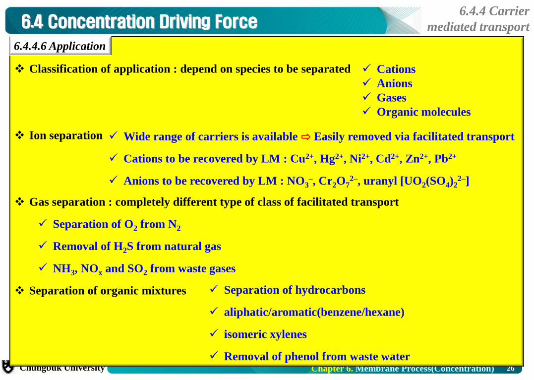
Classification of application : depend on species to be separated
Ion separation
Gas separation : completely different type of class of facilitated transport
Separation of O2 from N2
Removal of H2S from natural gas
NH3, NOx and SO2 from waste gases
Separation of organic mixtures
6.4.4.6 Application
Cations
Anions
Gases
Organic molecules
Wide range of carriers is available ⇨ Easily removed via facilitated transport
Cations to be recovered by LM : Cu2+, Hg2+, Ni2+, Cd2+, Zn2+, Pb2+
Anions to be recovered by LM : NO3–, Cr2O7
2–, uranyl [UO2(SO4)22–]
Separation of hydrocarbons
aliphatic/aromatic(benzene/hexane)
isomeric xylenes
Removal of phenol from waste water

27 Chapter 6. Membrane Process(Concentration) Chungbuk University
6.4 Concentration Driving Force 6.4.4 Carrier
mediated transport
6.4.4.7 Summary of carrier mediated transport
Items Characteristics
Membranes
Supported Liquid Membranes (SLM)
Emulsion Liquid Membranes (ELM)
Fixed carrier membranes
Solvent swollen membranes
Thickness 20 ∼ 150 μm (SLM), ≈ 0.1 ∼ l μm (ELM)
Pore sizes Non-porous (liquid !)
Driving force Concentration difference
Separation principle Affinity to carrier (carrier mediated transport)
Membrane material Hydrophobic porous membrane
Applications
Removal of specific ions
Cations (Cd, Cu, Ni, Pb)
Removal of gases
O2/N2 separation
Separation of organic liquids
Removal of phenol
Removal of H2S, CO2, SO2, CO, NH3
Anions (nitrate, chromate)