chapter 6-pneumatic transport
DESCRIPTION
Pneumatic TransportTRANSCRIPT

Pneumatic Transport
6.0 PNEUMATIC TRANSPORT 6.1 Introduction
For many years, gases have been used in industry to transport particulate solids.
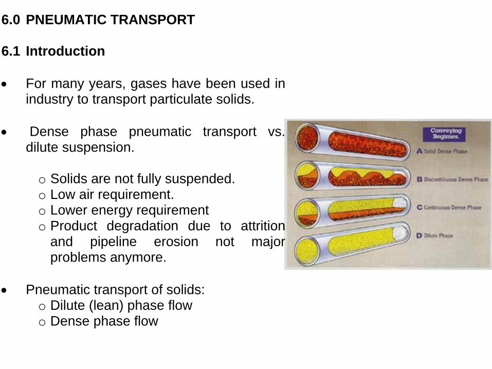
Dense phase pneumatic transport vs. dilute suspension.
o Solids are not fully suspended. o Low air requirement. o Lower energy requirement o Product degradation due to attrition
and pipeline erosion not major problems anymore.
Pneumatic transport of solids: o Dilute (lean) phase flow o Dense phase flow
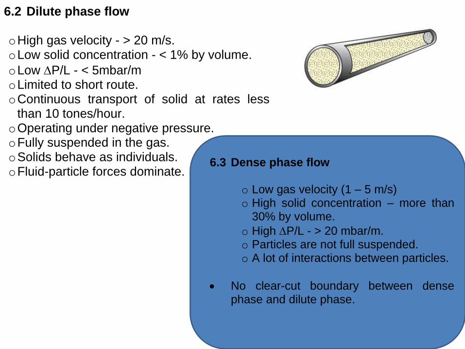
6.2 Dilute phase flow
o High gas velocity - > 20 m/s. o Low solid concentration - < 1% by volume.
o Low P/L - < 5mbar/m o Limited to short route. o Continuous transport of solid at rates less
than 10 tones/hour. o Operating under negative pressure. o Fully suspended in the gas. o Solids behave as individuals. o Fluid-particle forces dominate.
6.3 Dense phase flow
o Low gas velocity (1 – 5 m/s) o High solid concentration – more than
30% by volume.
o High P/L - > 20 mbar/m. o Particles are not full suspended. o A lot of interactions between particles.
No clear-cut boundary between dense phase and dilute phase.
Generally, ‘choking velocity’ and ‘saltation velocity’ are used to mark the boundary between dense phase and dilute phase flow.
Choking and Saltation velocities
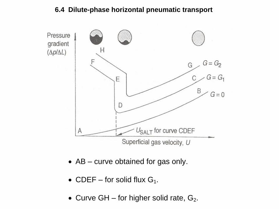
6.4 Dilute-phase horizontal pneumatic transport
AB – curve obtained for gas only.
CDEF – for solid flux G1.
Curve GH – for higher solid rate, G2.

Point C – the gas velocity is sufficiently high to carry all the solids in very dilute suspension.
As gas velocity reduces (at the same solid feed rate), the frictional resistance and
P/L decrease.
At point D – solids begin to settle out in the bottom pipe – saltation velocity, Usalt.
Further decease in gas velocity cause rapid salting out and rapid increase in
P/L as the area available for flow of gas is restricted by settled solids.
Region E to F – some solids move in dense phase and some in dilute phase.
Saltating velocity – marks the boundary between dilute phase flow and dense phase flow.
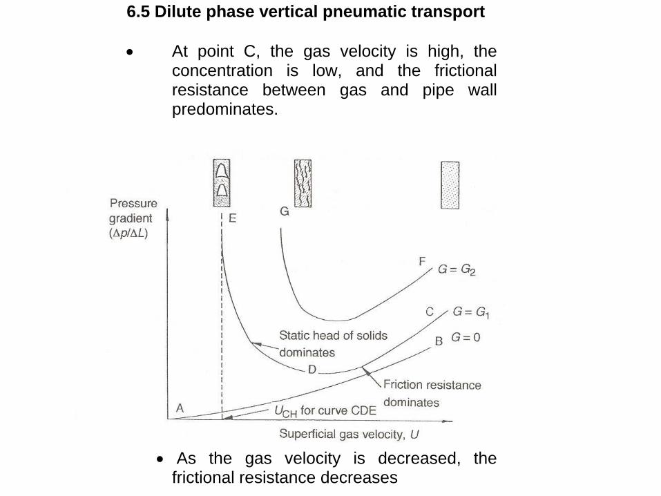
6.5 Dilute phase vertical pneumatic transport
At point C, the gas velocity is high, the concentration is low, and the frictional resistance between gas and pipe wall predominates.
As the gas velocity is decreased, the frictional resistance decreases

The concentration of suspension decrease, thus static head required to support the solid increases.
If the gas velocity is decreased below point D, then the increase in static head outweighs the decrease in fiction
resistance and P/L rises again.
If the gas velocity is decreased below point D, then the decrease in static head outweighs the decrease in frictional
resistance and P/L rises again.
In region DE, the decreasing velocity causes a rapid increase in solid concentration and a point is reached when the gas can no longer entrain all the solids.
At this point, slugging fluidized bed is formed in the vertical line.

6.6 Choking Velocity in Vertical Transport.
P across a length of transport line has 6 components
P due to acceleration of gas.
P due to particle acceleration.
P due to gas to pipe friction.
P due to solid to pipe friction.
P due to static head of the solids.
P due to static head of the gas.
Choking can be reached by decreasing the gas velocity at a constant solid flow rate, or by increasing the solid flow rate at a constant gas velocity.
Punwani correlation;
CHs
s
t
CH
CH GV
U
1 (6.1)
2
7.4
77.0 12250
t
CH
CH
CHT
g
VU
D
(6.2)
where A
MG s
s
Ms = mass of solid A = cross – sectional area of the pipe.
Assumption : USLIP = Vt
Equation (6.1) and (6.2) must be solved
simultaneously to give CH and UCH by using trial and error method.

6.7 The saltation velocity in horizontal transport
Rizk correlation (1973):
5.21100
96.1144010
1
d
SALT
d
SALTg
s
gD
U
AU
M
where AU
M
SALTg
s
is the solid loading’
mass of flowrate of solids mass flowrate of gas
and gD
U SALT
Froude Number at
saltation Rearranging above equation;
1
1
222104
g
s
SALT
DgMU
(6.3)
where 5.21100
95.11440
d
d

6.8 Gas and particles velocities
There are four types of velocities: Superficial gas velocity, Uo Actual gas velocity, Ug Solid velocity, Vs Slip velocity, USLIP
(i) Superficial gas velocity, Uo Operating gas velocity; Uo = volume flow of gas X-sectional area of pipe
A
QU o
(ii) Actual gas velocity, Ug
o
g
UU
(iii) Solid velocity, Vs
Us = Volume flow of solid
X-sectional area of pipe
A
QU s
S
1
s
s
UV
or 5.03.00638.01 sos dUV (6.4)
- Hinkle correlation.

(iv) Slip velocity, USLIP USLIP = Urel Urel = relative velocity between solid and gas Urel = Ug – Vs
It is often assumed that in vertical dilute phase flow, USLIP = Urel = Vt
6.8 6.9 Continuity Equations
For the particle:
sss AvM 1 (6.5)
For the gas:
ggg AUM (6.6)
Ratio of mass flowrates = solid loading
Solid loading =
gg
ss
g
s
U
v
M
M
1

6.8 6.10 Pressure drop along the pipeline
sinsin1
2
1
2
22
21
gLgL
LFLFvU
PPP
gs
swgwssgg
(1) - P due to gas acceleration
(2) - P due to particle acceleration
(3) - P due to gas-to-wall friction
(4) - P due to solid-to-wall friction
(5) - P due to static head of the solids
(6) - P due to static head of the gas
D
LUfLF
gg
gw
22
.
and
D
LvfLF sss
sw
2
.
12
- for horizontal flow
where
2
8
3
s
sg
D
s
g
sv
vU
d
DCf
D
gLGLF ssw 057.0. - for vertical flow
Konno and Saito (1969)
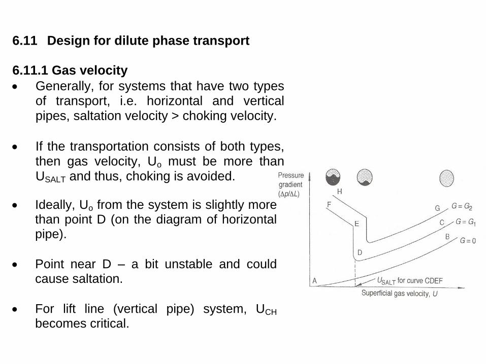
6.11 Design for dilute phase transport 6.11.1 Gas velocity
Generally, for systems that have two types of transport, i.e. horizontal and vertical pipes, saltation velocity > choking velocity.
If the transportation consists of both types, then gas velocity, Uo must be more than USALT and thus, choking is avoided.
Ideally, Uo from the system is slightly more than point D (on the diagram of horizontal pipe).
Point near D – a bit unstable and could cause saltation.
For lift line (vertical pipe) system, UCH
becomes critical.
If a small perturbation occurs in the line, it gives rise to an increase in solids feed rate, then pressure gradient in vertical line increases.
o Resulting in back pressure to the
blowers, and reduce volume flow of gas.
o Less gas means higher pressure gradient and the system reach choking condition.
Line that is filled with solid can be restarted by draining of the solid from line.
Thus, uncertainty in predicting choking
and saltation velocity allow 50% for safety margin.
Thus, for operating gas velocity,
UO = 1.5 USALT
6.11.2 Bends
Bends complicate the design. o Advisable to use as less bends as
possible.
o Increases P in line and points to create serious erosion and particle attrition.
Solids form salt at bends – o Due to centrifugal forces during traveling. o Particles slow down, re-entrained and
reaccelerated at bends.
Down flowing vertical to horizontal: o More tendency of saltation o Solid remain at the bottom of pipe for a
long distance before they disperse.
o Try to avoid down flowing vertical to horizontal bends at all possible in dilute pneumatic transport systems.
Zenz (1964) recommended blind tees to be used instead of sloping elbows: o Particles form cushion at the dead
branch – conveying particles impinge upon
stagnant ‘cushion’ instead of material walls.
–
Bodner (1982) found that: o Service life of blind tee is higher than
radius bends or elbow (15 times higher) because of the cushion.
o P and particle attrition rates for the blind tee is almost the same as radius bends.
Practically for bends:
P for bends = 7.5 m P of vertical lines.
Dilute-phase transport systems i.e. positive pressure and negative pressure – refer Figure 6.5 and 6.6 on page 151.

Discrete plug flow: discrete plugs of solids occupy the full pipe cross section.
Dune flow: layer of solids settled at the bottom of the pipe move along in the form of rolling dunes
Plug flow: A hybrid of discrete plug flow and dune flow in which the rolling dunes completely fill the pipe cross-section but in which there are no discrete plug.
Saltating flow: is encountered at gas velocities just below the saltation velocity. Particles are conveyed in suspension above a layer of settled solids. Particles may be deposited or re-entrained from this layer.